US7278181B2 - Vacuum cleaner with air bleed - Google Patents
Vacuum cleaner with air bleedDownload PDFInfo
- Publication number
- US7278181B2 US7278181B2US10/468,870US46887004AUS7278181B2US 7278181 B2US7278181 B2US 7278181B2US 46887004 AUS46887004 AUS 46887004AUS 7278181 B2US7278181 B2US 7278181B2
- Authority
- US
- United States
- Prior art keywords
- air inlet
- tool
- vacuum cleaner
- cleaner according
- bleed
- Prior art date
- Legal status (The legal status is an assumption and is not a legal conclusion. Google has not performed a legal analysis and makes no representation as to the accuracy of the status listed.)
- Expired - Lifetime, expires
Links
- 238000000926separation methodMethods0.000claimsabstractdescription17
- 239000000428dustSubstances0.000claimsabstractdescription11
- 238000004140cleaningMethods0.000description11
- 230000037361pathwayEffects0.000description6
- 230000000694effectsEffects0.000description4
- 238000013019agitationMethods0.000description3
- 230000009286beneficial effectEffects0.000description2
- 238000011144upstream manufacturingMethods0.000description2
- 230000015572biosynthetic processEffects0.000description1
- 230000015556catabolic processEffects0.000description1
- 238000001816coolingMethods0.000description1
- 238000006731degradation reactionMethods0.000description1
- 239000002783friction materialSubstances0.000description1
- 238000013021overheatingMethods0.000description1
- 239000002245particleSubstances0.000description1
- 239000004810polytetrafluoroethyleneSubstances0.000description1
- 229920001343polytetrafluoroethylenePolymers0.000description1
- 230000002265preventionEffects0.000description1
Images


Classifications
- A—HUMAN NECESSITIES
- A47—FURNITURE; DOMESTIC ARTICLES OR APPLIANCES; COFFEE MILLS; SPICE MILLS; SUCTION CLEANERS IN GENERAL
- A47L—DOMESTIC WASHING OR CLEANING; SUCTION CLEANERS IN GENERAL
- A47L9/00—Details or accessories of suction cleaners, e.g. mechanical means for controlling the suction or for effecting pulsating action; Storing devices specially adapted to suction cleaners or parts thereof; Carrying-vehicles specially adapted for suction cleaners
- A47L9/02—Nozzles
Definitions
- This inventionrelates to a vacuum cleaner.
- Vacuum cleanersare usually supplied with a range of tools for use with various cleaning situations that a user may encounter.
- An upright vacuum cleanerhas a wide, floor-engaging cleaner head at the base of the cleaner which is used for general floor cleaning.
- a range of smaller toolsmay also be supplied with the machine. These are usually attached to the end of a flexible hose of the cleaner.
- the toolsoften include a crevice tool for use in narrow, confined spaces, a stair tool and an upholstery tool with a brush head.
- a cylinder or canister vacuum cleanerhas a wide floor tool which is attached to the end of a cleaning wand for general floor cleaning and a similar range of smaller tools for use in other cleaning situations.
- any vacuum cleanerit is important to maintain a good flow rate of air into the floor tool and along the suction path of the cleaner to maintain good cleaning performance. This is particularly important with a cleaner that relies on cyclonic or centrifugal separation as the flow rate of dust-laden air within the cyclonic separating chamber is an important factor in determining the efficiency of the dust separation.
- toolsto include one or more bleed air inlets. As shown in FIG. 1 , the air inlet of a crevice tool 10 has a flat portion 12 , a notched portion 14 and an opening 15 . The notched portion 14 ensures that some air flows into the tool 10 even when the flat portion 12 is sealed against a surface.
- FIG. 2schematically shows a known type of cyclonic vacuum cleaner.
- the vacuum cleaner 100incorporates a floor tool 10 which is attached directly to a hose 114 .
- the hose 114is directly connected to dust-separating apparatus 116 .
- the dust-separating apparatus 116is a cyclonic separating apparatus using one or more cyclonic separation stages. Downstream of the dust-separating apparatus 116 is a pre-motor filter 120 , followed by a fan 122 which is driven by a motor 124 .
- a further filter 126is located after the motor 124 .
- a bleed valve 118is located on the dust-separating apparatus.
- the bleed valve 118is arranged to admit air into the separating apparatus when the flow of air along the airflow path is significantly reduced.
- the bleed valvecan respond to the pressure along the airflow path reducing to a predetermined absolute value, or to the difference in pressure between two parts of the airflow path reaching a predetermined value.
- the motor 124operates to activate the fan 122 which causes a flow of air to pass from the floor tool 10 to the dust-separating apparatus 116 via the hose 114 . After separation has taken place, the airflow passes through the pre-motor filter 120 , past the fan 122 , past the motor 124 providing a cooling effect, and through the post-motor filter 126 before being expelled to the atmosphere.
- a bleed valve 118is arranged such that, if the pressure within the dust-separating apparatus 116 , and particularly at the location within the dust-separating apparatus 116 at which the bleed valve 118 is placed, drops below a pre-determined value, the bleed valve 118 opens so as to allow air from the atmosphere to enter the cyclonic dust-separating apparatus in order to maintain an adequate airflow to effect separation.
- the prevention of the airflow from falling below a predetermined levelhelps to ensure that the motor 124 is adequately cooled so as to prevent any risk of overheating in the event of a blockage occurring in the airflow path upstream of the bleed valve 118 .
- the present inventionseeks to obviate the need for a bleed valve along the airflow path to the separator.
- the present inventionprovides a vacuum cleaner comprising a cyclonic separator for separating dirt and dust from an incoming airflow, a tool and a suction conduit for connecting the tool to the separator, wherein the tool comprises a housing or body defining a suction path, the body having a main air inlet aperture for engaging with a surface to be cleaned and for allowing dirty air to enter the suction path, and a bleed air inlet for allowing air to bleed into the suction path, the bleed air inlet being located such that it is separate from the main air inlet aperture and wherein the bleed air inlet is permanently open and the bleed air inlet has a cross-sectional area such that, in use, it admits a sufficient quantity of air to maintain adequate separation efficiency in the separator of the cleaner when the main air inlet aperture is fully blocked.
- the bleed air inletadmits a sufficient quantity of air to maintain adequate separation efficiency in the vacuum cleaner, even when the main air inlet aperture to the tool is fully blocked. This is particularly important in a vacuum cleaner which uses a set of small, parallel cyclonic separators where there is a risk that the separators could become blocked if the flow rate reduces below a critical value since the vortex cannot form. Also, the provision of a continuous flow of bled air through the tool into the suction path reduces or avoids sudden changes in airflow through the separation apparatus, which minimises the risk of dirt becoming re-entrained in the airflow through the separator. This extends the life of filters placed after the separation apparatus.
- the provision of the bleed air inletcan also avoid the need for a bleed air valve located further downstream along the suction path, which reduces the overall cost of the cleaner.
- the continuous provision of bled airalso reduces the force that is required by a user to push the tool along a surface.
- the bleed air inlet of the toolis located such that it is spaced from the main air inlet aperture and directs air into the suction channel towards the main aperture.
- the toolincludes an upper face, such as a portion of the tool body that faces generally away from the surface to be cleaned when the main inlet aperture is engaged on the surface.
- the bleed air inletcan be located on the upper face of the tool. This position of the bleed air inlet ensures that the bled air helps to agitate the surface that is being cleaned and thus results in more dirt, fluff and other debris being removed from the surface.
- the provision of the bleed air inletimproves the cleaning performance of the tool at all times, whether the main air inlet aperture is blocked or not.
- the bleed air inletis a plurality of apertures. These can be spaced across the tool. Each of the apertures of the bleed air inlet includes an inlet.
- the toolis configured such that when the main air inlet aperture is engaged on the surface to be cleaned, the inlets to the apertures are disposed at relatively different heights with respect to the surface.
- the bleed air inlet or inletshas a guide channel for guiding the flow of air.
- the main air inlet aperturegenerally occupies a plane, and it has been found that providing the bleed air inlet in a direction which is substantially perpendicular to the plane of the main air inlet aperture provides a particularly effective cleaning effect.
- the tool bodyhas an outlet to allow flow to exit the tool from the suction path.
- the angle of the bleed air inlet with respect to the longitudinal axis of the air outlet of the tool bodyhas an effect on the cleaning performance of the tool. By aligning the bleed air inlet such that it points away from the longitudinal axis of the outlet, a greater proportion of the bled air is likely to strike or to pass through the floor surface beneath the main air inlet. It has been found particularly beneficial to cause the bled air to flow through an obtuse angle, and preferably an angle approaching 180°.
- the toolalso includes an agitator mounted within the body for agitating the surface to be cleaned.
- the agitatormay be a comb or brush.
- the bleed air inletis preferably located such that it directs bled air towards a distal end of the agitator, where the agitator meets the surface.
- the bodyincludes an outlet to allow flow to exit the tool from the suction path, and the bleed air inlet is directed at an angle with respect to the air outlet that is greater than 90°.
- the cross-sectional area of the bleed air inletis sufficient to allow, in use, a flow rate of at least 20 liters per second through the tool.
- the cross-sectional area of the bleed air inletis sufficient to allow, in use, a flow rate above that at which the separators would become blocked.
- the toolmay be a configured as any one of a variety of types of vacuum tools.
- the toolmay be crevice tool or a stair tool.
- FIG. 1shows a known type of tool for a vacuum cleaner
- FIG. 2schematically shows the parts of a known cyclonic vacuum cleaner
- FIGS. 3 and 4show a first embodiment of a tool which can be used in the present invention
- FIG. 5is a cross-section through the tool of FIG. 3 ;
- FIGS. 6 to 8show a second embodiment of a tool which can be used in the present invention.
- FIGS. 9 and 10are cross-sections through the tool of FIG. 6 ;
- FIG. 11schematically shows a cyclonic vacuum cleaner using the floor tools of FIGS. 3 to 10 ;
- FIG. 12shows a further tool which can be used in the invention.
- FIGS. 3 to 5show a stair tool 300 which is used for cleaning stairs and areas which cannot readily be reached by a full-sized tool.
- FIG. 5shows a cross-section along A-A of FIG. 4 .
- the toolhas a body with a neck 301 for connecting a suction hose or wand of a vacuum cleaner.
- the bodydefines a suction path or suction passageway 350 .
- the lower face of the tool as shown in FIG. 4has a main air inlet aperture 305 , depicted in FIG. 5 as main suction opening 330 , which allows air to enter the suction passageway 350 .
- the main inlet aperture 305 or main suction opening 330is intended to be pressed against a surface which is to be cleaned.
- FIG. 5shows a cross-section along A-A of FIG. 4 .
- the toolhas a body with a neck 301 for connecting a suction hose or wand of a vacuum cleaner.
- the bodydefines a suction
- the tool 300includes an agitator, such as comb 320 , which is positioned within the suction passageway 350 and extends downwardly towards the main suction opening 330 .
- the combhas a formation of alternate fingers and openings when viewed in the direction X of FIG. 4 , the fingers extending towards the inlet aperture 305 or suction opening 330 .
- the cross-section of FIG. 5shows the lowermost, distal end of one of the fingers of the comb.
- the combserves to agitate the floor surface when it is pushed forwards and backwards across the surface.
- a set of bleed air inlets 310is located across the width of the tool 300 .
- the toolhas an upper face that faces generally away from the surface to be cleaned when the main suction opening 330 is engaged thereon.
- Each of these inletsextends from the upper face towards the main suction opening 330 .
- the inlets 310 in this toolare perpendicular to the plane of the main suction opening 330 .
- a pathwayexists between the lowermost part of the bleed air inlets and the main passageway 350 , through the comb 320 . This pathway exists even when the tool is pressed fully against a surface.
- Eight inletsare shown, spaced across the full width of the tool, but other numbers of inlets are possible. The inlets could be confined to only part of the width of the tool, but we have found best results are achieved when the inlets are spaced across the full width of the tool.
- airis drawn through the main suction opening 330 .
- This airflowpasses through the pile of a carpeted surface, carrying dirt and dust with it, and then flows along passageway 350 towards the cleaner.
- a secondary flow of airenters the tool via inlets 310 .
- This secondary air or bled airis directed towards the surface which is pressed against the main suction opening 330 .
- Some of the airwill be drawn through the pile of the carpeted surface before flowing along passageway 350 .
- Other airmay flow directly from inlet 310 to passageway 350 , bypassing the carpeted surface.
- the combination of air being drawn through the surface from the sides and abovehelps to increase the agitation of the floor surface. Also, air will still be able to freely flow into the tool via inlets 310 when the surface is very thickly piled and when there is little or no flow in direction 360 .
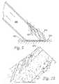
- FIGS. 6 to 8show a crevice tool, with FIG. 8 showing a cross-section along B-B of FIG. 6 .
- a crevice toolis typically sued to clean confined areas.
- the toolhas a body with a neck 601 for connecting to a suction hose or wand of a vacuum cleaner.
- the lower face of the toolhas a main suction opening 630 which is intended to be pressed against a surface which is to be cleaned.
- a set of bleed air inlets 610 separated by vanes 611is located on the lowermost part of the upper surface of the tool 600 , the inlets being positioned one behind the other. Each of these inlets 610 extends from the upper face towards the main suction opening 630 .
- the inlets 610 in this toolare set at an angle of around 70° to the plane of the main suction opening 630 although this angle could be perpendicular, as with the tool of FIG. 3 , or some other angle.
- the inlets 610are directed away from the longitudinal axis of the main passageway 650 , thus ensuring that air which flows into the tool via inlets 610 is forced to make a ‘u-turn’ of 155° in order to flow out of the tool along the passageway 650 . This is shown more clearly in FIG. 10 .
- a pathwayexists between the lowermost part of the bleed air inlets and the main passageway 650 . This pathway exists even when the tool is pressed fully against a surface.
- Four inletsare shown, but other numbers of inlets are possible.
- FIG. 9shows the main directions of airflow
- FIG. 10shows a more detailed plot of airflow.
- Airis drawn through the main suction opening 630 .
- This airflowpasses through the pile of a carpeted surface, carrying dirt and dust with it, and then flows along passageway 650 towards the cleaner.
- a secondary flow of airenters the tool via inlets 610 .
- This secondary air or bled airis directed towards the surface which is pressed against the main suction opening 630 .
- Some of the airwill be drawn through the pile of the carpeted surface before flowing along passageway 650 .
- Other airmay flow directly from inlet 610 to passageway 650 , bypassing the carpeted surface.
- FIG. 11schematically shows a cyclonic vacuum cleaner 800 which uses the tools described above.
- FIG. 11most of the parts of the cleaner are the same as shown in FIG. 1 and have the same reference numbers.
- the tool 10has been replaced by one of the tools 300 , 600 which have bleed air inlets. Since air can now flow along the airflow path even when the main inlet of the tool is blocked, effective separation can be maintained in separation apparatus 116 without the need for the bleed valve 118 .
- a bleed valve 810can be fitted downstream of the separator and pre-motor filter 120 to ensure that the motor will not overheat when the filter 120 becomes blocked.
- the cross-sectional area of the bleed air inlets 310 , 610is chosen such that, even when the main air inlet is fully sealed against a surface, the flow rate of air through the tool will be sufficient to maintain adequate separation efficiency in the dust-separating apparatus of the cleaner. It has been found that dimensioning the inlets 310 , 610 to ensure a minimum flow rate of 20 liters per second through the tool provides good separation.
- the bleed valve 118 of FIG. 1could be used in its original position along with the tools 300 , 600 .
- the increased cleaning performance of the toolsprovides a beneficial effect, and the bleed valve 118 opens in the event that a blockage occurs somewhere between the tools 300 , 600 and the dust-separating apparatus.
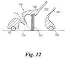
- FIG. 12shows a cross-section through a further embodiment of a tool.
- the toolhas a body 705 with a neck 701 for connecting to a suction hose or wand of a vacuum cleaner.
- the bodydefines a suction path therethrough.
- the lower face of the toolhas a main air inlet aperture or main suction opening 730 which is intended to be pressed against a surface which is to be cleaned, the main suction opening allowing air to enter the suction path.
- a set of bleed air inlets 710are located on the lowermost part of the upper surface of the tool 700 . Each of these inlets 710 extend from the upper face towards the main suction opening 730 .
- a brush 740is positioned within the housing and extends towards the plane of the suction opening 730 .
- the bleed air inlets 710are configured such that bled air is generally directed toward a distal end of the agitator. For example, in the embodiment illustrated in FIG. 12 , the bled air will strike the carpet at the base of the brush, where the distal end of the brush meets the surface to be cleaned, thus subjecting the surface to agitation by both the brush and the bled air.
- the inlets 710 in this toolare set at an angle of around 45-60° to the plane of the main suction opening 730 , although this angle could be varied.
Landscapes
- Engineering & Computer Science (AREA)
- Mechanical Engineering (AREA)
- Filters For Electric Vacuum Cleaners (AREA)
- Nozzles For Electric Vacuum Cleaners (AREA)
- Addition Polymer Or Copolymer, Post-Treatments, Or Chemical Modifications (AREA)
- Cyclones (AREA)
- Grinding-Machine Dressing And Accessory Apparatuses (AREA)
Abstract
Description
Claims (16)
Applications Claiming Priority (3)
| Application Number | Priority Date | Filing Date | Title |
|---|---|---|---|
| GB0104675.4 | 2001-02-24 | ||
| GBGB0104675.4AGB0104675D0 (en) | 2001-02-24 | 2001-02-24 | A tool for a vacuum cleaner |
| PCT/GB2002/000609WO2002067746A1 (en) | 2001-02-24 | 2002-02-12 | A vacuum cleaner |
Publications (2)
| Publication Number | Publication Date |
|---|---|
| US20040128789A1 US20040128789A1 (en) | 2004-07-08 |
| US7278181B2true US7278181B2 (en) | 2007-10-09 |
Family
ID=9909496
Family Applications (1)
| Application Number | Title | Priority Date | Filing Date |
|---|---|---|---|
| US10/468,870Expired - LifetimeUS7278181B2 (en) | 2001-02-24 | 2002-02-12 | Vacuum cleaner with air bleed |
Country Status (12)
| Country | Link |
|---|---|
| US (1) | US7278181B2 (en) |
| EP (1) | EP1361812B1 (en) |
| JP (1) | JP2004537336A (en) |
| CN (1) | CN1305428C (en) |
| AT (1) | ATE273650T1 (en) |
| AU (1) | AU2002229966B2 (en) |
| CA (1) | CA2439032C (en) |
| DE (1) | DE60201019T2 (en) |
| ES (1) | ES2225771T3 (en) |
| GB (1) | GB0104675D0 (en) |
| MY (1) | MY131996A (en) |
| WO (2) | WO2002067746A1 (en) |
Cited By (69)
| Publication number | Priority date | Publication date | Assignee | Title |
|---|---|---|---|---|
| US20080222837A1 (en)* | 2006-10-20 | 2008-09-18 | Dieter Kaffenberger | Compact vacuum cleaning device |
| US20100175217A1 (en)* | 2007-08-29 | 2010-07-15 | G.B.D. Corp. | Cyclonic surface cleaning apparatus with externally positioned dirt chamber |
| US20100251506A1 (en)* | 2009-03-11 | 2010-10-07 | G.B.D. Corp. | Configuration of a surface cleaning apparatus |
| USD626708S1 (en) | 2008-03-11 | 2010-11-02 | Royal Appliance Mfg. Co. | Hand vacuum |
| US20100319159A1 (en)* | 2009-06-17 | 2010-12-23 | Dyson Technology Limited | Tool for a surface treating appliance |
| US20110010889A1 (en)* | 2009-03-12 | 2011-01-20 | Dyson Technology Limited | Surface treating head |
| US20110047746A1 (en)* | 2009-09-01 | 2011-03-03 | Mark Butts | Vacuum cleaner accessory tool having a removable brush |
| US20110047744A1 (en)* | 2009-09-01 | 2011-03-03 | Bozzelli Robert F | Vacuum cleaner accessory tool |
| US8069529B2 (en) | 2008-10-22 | 2011-12-06 | Techtronic Floor Care Technology Limited | Handheld vacuum cleaner |
| US9027198B2 (en) | 2013-02-27 | 2015-05-12 | G.B.D. Corp. | Surface cleaning apparatus |
| US9161669B2 (en) | 2013-03-01 | 2015-10-20 | Omachron Intellectual Property Inc. | Surface cleaning apparatus |
| US9204773B2 (en) | 2013-03-01 | 2015-12-08 | Omachron Intellectual Property Inc. | Surface cleaning apparatus |
| US9227201B2 (en) | 2013-02-28 | 2016-01-05 | Omachron Intellectual Property Inc. | Cyclone such as for use in a surface cleaning apparatus |
| US9227151B2 (en) | 2013-02-28 | 2016-01-05 | Omachron Intellectual Property Inc. | Cyclone such as for use in a surface cleaning apparatus |
| US9238235B2 (en) | 2013-02-28 | 2016-01-19 | Omachron Intellectual Property Inc. | Cyclone such as for use in a surface cleaning apparatus |
| US9295995B2 (en) | 2013-02-28 | 2016-03-29 | Omachron Intellectual Property Inc. | Cyclone such as for use in a surface cleaning apparatus |
| US9314139B2 (en) | 2014-07-18 | 2016-04-19 | Omachron Intellectual Property Inc. | Portable surface cleaning apparatus |
| US9320401B2 (en) | 2013-02-27 | 2016-04-26 | Omachron Intellectual Property Inc. | Surface cleaning apparatus |
| US9326652B2 (en) | 2013-02-28 | 2016-05-03 | Omachron Intellectual Property Inc. | Surface cleaning apparatus |
| US9420925B2 (en) | 2014-07-18 | 2016-08-23 | Omachron Intellectual Property Inc. | Portable surface cleaning apparatus |
| US9427126B2 (en) | 2013-03-01 | 2016-08-30 | Omachron Intellectual Property Inc. | Surface cleaning apparatus |
| US9433332B2 (en) | 2013-02-27 | 2016-09-06 | Omachron Intellectual Property Inc. | Surface cleaning apparatus |
| US9451855B2 (en) | 2013-02-28 | 2016-09-27 | Omachron Intellectual Property Inc. | Surface cleaning apparatus |
| US9451853B2 (en) | 2014-07-18 | 2016-09-27 | Omachron Intellectual Property Inc. | Portable surface cleaning apparatus |
| US9545181B2 (en) | 2006-12-15 | 2017-01-17 | Omachron Intellectual Property Inc. | Surface cleaning apparatus |
| US9585530B2 (en) | 2014-07-18 | 2017-03-07 | Omachron Intellectual Property Inc. | Portable surface cleaning apparatus |
| US9591958B2 (en) | 2013-02-27 | 2017-03-14 | Omachron Intellectual Property Inc. | Surface cleaning apparatus |
| US9655485B2 (en) | 2013-12-18 | 2017-05-23 | Aktiebolaget Electrolux | Vacuum cleaner suction nozzle with height adjustment and bleed valve |
| US9693666B2 (en) | 2011-03-04 | 2017-07-04 | Omachron Intellectual Property Inc. | Compact surface cleaning apparatus |
| US9770148B2 (en) | 2013-10-11 | 2017-09-26 | Zenith Technologies, Llc | Vacuum cleaner with adjustable vent |
| US9820621B2 (en) | 2013-02-28 | 2017-11-21 | Omachron Intellectual Property Inc. | Surface cleaning apparatus |
| US9888817B2 (en) | 2014-12-17 | 2018-02-13 | Omachron Intellectual Property Inc. | Surface cleaning apparatus |
| US9924842B2 (en)* | 2014-06-30 | 2018-03-27 | Bissell Homecare, Inc. | Vacuum cleaner |
| US9949601B2 (en) | 2007-08-29 | 2018-04-24 | Omachron Intellectual Property Inc. | Cyclonic surface cleaning apparatus |
| US10080472B2 (en) | 2010-03-12 | 2018-09-25 | Omachron Intellectual Property Inc. | Hand carriable surface cleaning apparatus |
| US10136778B2 (en) | 2014-12-17 | 2018-11-27 | Omachron Intellectual Property Inc. | Surface cleaning apparatus |
| US10165912B2 (en) | 2006-12-15 | 2019-01-01 | Omachron Intellectual Property Inc. | Surface cleaning apparatus |
| US20190008346A1 (en)* | 2017-07-06 | 2019-01-10 | Omachron Intellectual Property Inc. | Handheld surface cleaning apparatus |
| US10251519B2 (en) | 2014-12-17 | 2019-04-09 | Omachron Intellectual Property Inc. | Surface cleaning apparatus |
| US10456000B2 (en) | 2015-01-28 | 2019-10-29 | Techtronic Industries Co. Ltd. | Surface cleaning head with a valve assembly |
| US10537216B2 (en) | 2017-07-06 | 2020-01-21 | Omachron Intellectual Property Inc. | Handheld surface cleaning apparatus |
| US10548442B2 (en) | 2009-03-13 | 2020-02-04 | Omachron Intellectual Property Inc. | Portable surface cleaning apparatus |
| US10631693B2 (en) | 2017-07-06 | 2020-04-28 | Omachron Intellectual Property Inc. | Handheld surface cleaning apparatus |
| US10702113B2 (en) | 2017-07-06 | 2020-07-07 | Omachron Intellectual Property Inc. | Handheld surface cleaning apparatus |
| US10722086B2 (en) | 2017-07-06 | 2020-07-28 | Omachron Intellectual Property Inc. | Handheld surface cleaning apparatus |
| US10750913B2 (en) | 2017-07-06 | 2020-08-25 | Omachron Intellectual Property Inc. | Handheld surface cleaning apparatus |
| US10765277B2 (en) | 2006-12-12 | 2020-09-08 | Omachron Intellectual Property Inc. | Configuration of a surface cleaning apparatus |
| US10842330B2 (en) | 2017-07-06 | 2020-11-24 | Omachron Intellectual Property Inc. | Handheld surface cleaning apparatus |
| US11006799B2 (en) | 2018-08-13 | 2021-05-18 | Omachron Intellectual Property Inc. | Cyclonic air treatment member and surface cleaning apparatus including the same |
| US11013378B2 (en) | 2018-04-20 | 2021-05-25 | Omachon Intellectual Property Inc. | Surface cleaning apparatus |
| US11013384B2 (en) | 2018-08-13 | 2021-05-25 | Omachron Intellectual Property Inc. | Cyclonic air treatment member and surface cleaning apparatus including the same |
| US11033162B1 (en) | 2019-12-12 | 2021-06-15 | Zenith Technologies, Llc | Vacuum cleaner having flexible vent members |
| US11192122B2 (en) | 2018-08-13 | 2021-12-07 | Omachron Intellectual Property Inc. | Cyclonic air treatment member and surface cleaning apparatus including the same |
| US11445878B2 (en) | 2020-03-18 | 2022-09-20 | Omachron Intellectual Property Inc. | Surface cleaning apparatus with removable air treatment member assembly |
| US11666193B2 (en) | 2020-03-18 | 2023-06-06 | Omachron Intellectual Property Inc. | Surface cleaning apparatus with removable air treatment member assembly |
| US11690489B2 (en) | 2009-03-13 | 2023-07-04 | Omachron Intellectual Property Inc. | Surface cleaning apparatus with an external dirt chamber |
| US11730327B2 (en) | 2020-03-18 | 2023-08-22 | Omachron Intellectual Property Inc. | Surface cleaning apparatus with removable air treatment assembly |
| US11751733B2 (en) | 2007-08-29 | 2023-09-12 | Omachron Intellectual Property Inc. | Portable surface cleaning apparatus |
| US11766156B2 (en) | 2020-03-18 | 2023-09-26 | Omachron Intellectual Property Inc. | Surface cleaning apparatus with removable air treatment member assembly |
| US11771281B2 (en) | 2020-03-18 | 2023-10-03 | Omachron Intellectual Property Inc. | Surface cleaning apparatus |
| US11779174B2 (en) | 2016-04-11 | 2023-10-10 | Omachron Intellectual Property Inc. | Surface cleaning apparatus |
| US11857142B2 (en) | 2006-12-15 | 2024-01-02 | Omachron Intellectual Property Inc. | Surface cleaning apparatus having an energy storage member and a charger for an energy storage member |
| US11857140B2 (en) | 2013-02-28 | 2024-01-02 | Omachron Intellectual Property Inc. | Cyclone such as for use in a surface cleaning apparatus |
| US11903546B2 (en) | 2014-12-17 | 2024-02-20 | Omachron Intellectual Property Inc. | Surface cleaning apparatus |
| US11937762B2 (en) | 2019-06-26 | 2024-03-26 | Milwaukee Electric Tool Corporation | Vacuum tools |
| US12048409B2 (en) | 2007-03-11 | 2024-07-30 | Omachron Intellectual Property Inc. | Portable surface cleaning apparatus |
| US12213640B2 (en) | 2009-03-13 | 2025-02-04 | Omachron Intellectual Property Inc. | Surface cleaning apparatus |
| US12220099B2 (en) | 2006-12-12 | 2025-02-11 | Omachron Intellectual Property Inc. | Surface cleaning apparatus |
| US12251716B2 (en) | 2016-12-27 | 2025-03-18 | Omachron Intellectual Property Inc. | Surface cleaning apparatus |
Families Citing this family (13)
| Publication number | Priority date | Publication date | Assignee | Title |
|---|---|---|---|---|
| GB0220277D0 (en)* | 2002-08-31 | 2002-10-09 | North John H | Improvements in and relating to particle separation apparatus |
| GB2401310A (en)* | 2004-03-12 | 2004-11-10 | Dyson Ltd | Vacuum cleaner nozzle attachment |
| KR100613102B1 (en)* | 2004-07-01 | 2006-08-17 | 삼성광주전자 주식회사 | Suction structure assembly and vacuum cleaner with same |
| DE202005018081U1 (en)* | 2005-11-19 | 2007-04-05 | Melitta Haushaltsprodukte Gmbh & Co. Kg | Nozzle, especially for vacuum cleaner, has at least one suction passage formed on nozzle body and spaced at distance from base, and suction passage is open towards base and leads to suction slot via deflection |
| GB0615684D0 (en) | 2006-08-08 | 2006-09-13 | Dyson Technology Ltd | An attachment for a cleaning appliance |
| GB2465103B (en)* | 2008-05-20 | 2010-08-11 | Richards Morphy N I Ltd | Improvements in and relating to vacuum cleaners |
| GB2477138B (en)* | 2010-01-25 | 2014-03-19 | Dyson Technology Ltd | A floor tool |
| AU2010201569B2 (en)* | 2010-04-20 | 2012-12-06 | Morphy Richards Limited | Improvements in and relating to vacuum cleaners |
| DE102011051683A1 (en)* | 2011-07-08 | 2013-01-10 | Miele & Cie. Kg | Method for operating a vacuum cleaner with a cyclone separator and vacuum cleaner with a cyclone separator |
| DE102011081044A1 (en)* | 2011-08-16 | 2013-02-21 | BSH Bosch und Siemens Hausgeräte GmbH | Dust separator, in particular for vacuum cleaners |
| USD737529S1 (en)* | 2014-02-12 | 2015-08-25 | Gutter-Vac International Pty Ltd | Drum lid for a gutter vacuum |
| JP5971289B2 (en)* | 2014-08-20 | 2016-08-17 | 株式会社 イアス | Substrate local automatic analyzer and analysis method |
| JP7107594B2 (en)* | 2020-12-16 | 2022-07-27 | アイリスオーヤマ株式会社 | Vacuum cleaner |
Citations (22)
| Publication number | Priority date | Publication date | Assignee | Title |
|---|---|---|---|---|
| US1468467A (en)* | 1921-10-31 | 1923-09-18 | William W Farnsworth | Cleaning apparatus |
| US1778935A (en)* | 1928-04-21 | 1930-10-21 | Air Way Electric Appl Corp | Suction nozzle for vacuum cleaners |
| GB958445A (en) | 1961-10-31 | 1964-05-21 | Siemens Elektrogeraete Gmbh | Improvements in or relating to suction cleaner nozzles |
| FR1434272A (en) | 1965-02-19 | 1966-04-08 | Paris & Du Rhone | Vacuum cleaner nozzle |
| BE721011A (en) | 1968-09-18 | 1969-03-03 | ||
| US3550183A (en)* | 1968-01-11 | 1970-12-29 | Haley Corp | Cleaning tool for vacuum cleaner |
| DE1628562A1 (en) | 1966-04-13 | 1971-02-18 | Determann Hermann Dr Ing | Suction head for vacuum cleaner |
| US4091496A (en) | 1975-10-28 | 1978-05-30 | Wilfrid Desrosiers | Vacuum cleaner nozzle |
| EP0042723B1 (en) | 1980-06-19 | 1985-08-21 | Rotork Appliances Limited | Vacuum cleaning appliance |
| GB2159696A (en) | 1984-05-22 | 1985-12-11 | Rotowash Ltd | Suction cleaning/spray head |
| WO1986001240A1 (en) | 1984-08-08 | 1986-02-27 | Ing. Alfred Schmidt Gmbh | Suction device |
| US4976005A (en) | 1989-06-12 | 1990-12-11 | Dale L Grave | Cleaning tool with demand-responsive air port |
| WO1994000046A1 (en) | 1992-06-24 | 1994-01-06 | Notetry Limited | Dual cyclonic vacuum cleaner |
| WO1998002080A1 (en) | 1996-07-15 | 1998-01-22 | Notetry Limited | Apparatus for separating particles from a fluid flow and a valve for introducing bled fluid to a mainstream fluid |
| JPH10211134A (en) | 1997-01-29 | 1998-08-11 | Matsushita Electric Ind Co Ltd | Vacuum cleaner suction tool |
| JPH10323303A (en) | 1997-05-27 | 1998-12-08 | Mitsubishi Electric Corp | Vacuum cleaner suction tool |
| JPH11123164A (en)* | 1997-10-22 | 1999-05-11 | Mitsubishi Electric Corp | Vacuum cleaner suction tool |
| JPH11137487A (en)* | 1997-11-13 | 1999-05-25 | Mitsubishi Electric Corp | Vacuum cleaner suction tool |
| US5920954A (en) | 1995-01-30 | 1999-07-13 | Increa Oy | Device for cleaning |
| US6032328A (en) | 1998-02-10 | 2000-03-07 | Rexair, Inc. | Crevice cleaning tool for a vacuum cleaner apparatus |
| JP2000093361A (en)* | 1998-09-18 | 2000-04-04 | Mitsubishi Electric Corp | Vacuum cleaner gap nozzle |
| US6334234B1 (en)* | 1999-01-08 | 2002-01-01 | Fantom Technologies Inc. | Cleaner head for a vacuum cleaner |
Family Cites Families (2)
| Publication number | Priority date | Publication date | Assignee | Title |
|---|---|---|---|---|
| JPH072158B2 (en)* | 1990-06-28 | 1995-01-18 | 三洋電機株式会社 | Floor suction |
| JP3202953B2 (en)* | 1996-12-26 | 2001-08-27 | 東芝テック株式会社 | Vacuum cleaner suction body |
- 2001
- 2001-02-24GBGBGB0104675.4Apatent/GB0104675D0/ennot_activeCeased
- 2002
- 2002-02-12AUAU2002229966Apatent/AU2002229966B2/ennot_activeCeased
- 2002-02-12CACA002439032Apatent/CA2439032C/ennot_activeExpired - Fee Related
- 2002-02-12WOPCT/GB2002/000609patent/WO2002067746A1/enactiveIP Right Grant
- 2002-02-12USUS10/468,870patent/US7278181B2/ennot_activeExpired - Lifetime
- 2002-02-12WOPCT/GB2002/000616patent/WO2002067747A1/ennot_activeApplication Discontinuation
- 2002-02-12CNCNB028052234Apatent/CN1305428C/ennot_activeExpired - Fee Related
- 2002-02-12ATAT02711072Tpatent/ATE273650T1/ennot_activeIP Right Cessation
- 2002-02-12ESES02711072Tpatent/ES2225771T3/ennot_activeExpired - Lifetime
- 2002-02-12DEDE60201019Tpatent/DE60201019T2/ennot_activeExpired - Lifetime
- 2002-02-12JPJP2002567124Apatent/JP2004537336A/enactivePending
- 2002-02-12EPEP02711072Apatent/EP1361812B1/ennot_activeExpired - Lifetime
- 2002-02-21MYMYPI20020590Apatent/MY131996A/enunknown
Patent Citations (23)
| Publication number | Priority date | Publication date | Assignee | Title |
|---|---|---|---|---|
| US1468467A (en)* | 1921-10-31 | 1923-09-18 | William W Farnsworth | Cleaning apparatus |
| US1778935A (en)* | 1928-04-21 | 1930-10-21 | Air Way Electric Appl Corp | Suction nozzle for vacuum cleaners |
| GB958445A (en) | 1961-10-31 | 1964-05-21 | Siemens Elektrogeraete Gmbh | Improvements in or relating to suction cleaner nozzles |
| FR1434272A (en) | 1965-02-19 | 1966-04-08 | Paris & Du Rhone | Vacuum cleaner nozzle |
| DE1628562A1 (en) | 1966-04-13 | 1971-02-18 | Determann Hermann Dr Ing | Suction head for vacuum cleaner |
| US3550183A (en)* | 1968-01-11 | 1970-12-29 | Haley Corp | Cleaning tool for vacuum cleaner |
| BE721011A (en) | 1968-09-18 | 1969-03-03 | ||
| US4091496A (en) | 1975-10-28 | 1978-05-30 | Wilfrid Desrosiers | Vacuum cleaner nozzle |
| EP0042723B1 (en) | 1980-06-19 | 1985-08-21 | Rotork Appliances Limited | Vacuum cleaning appliance |
| GB2159696A (en) | 1984-05-22 | 1985-12-11 | Rotowash Ltd | Suction cleaning/spray head |
| WO1986001240A1 (en) | 1984-08-08 | 1986-02-27 | Ing. Alfred Schmidt Gmbh | Suction device |
| US4976005A (en) | 1989-06-12 | 1990-12-11 | Dale L Grave | Cleaning tool with demand-responsive air port |
| WO1994000046A1 (en) | 1992-06-24 | 1994-01-06 | Notetry Limited | Dual cyclonic vacuum cleaner |
| US5920954A (en) | 1995-01-30 | 1999-07-13 | Increa Oy | Device for cleaning |
| WO1998002080A1 (en) | 1996-07-15 | 1998-01-22 | Notetry Limited | Apparatus for separating particles from a fluid flow and a valve for introducing bled fluid to a mainstream fluid |
| GB2315231A (en) | 1996-07-15 | 1998-01-28 | Notetry Ltd | Apparatus for Separating Particles |
| JPH10211134A (en) | 1997-01-29 | 1998-08-11 | Matsushita Electric Ind Co Ltd | Vacuum cleaner suction tool |
| JPH10323303A (en) | 1997-05-27 | 1998-12-08 | Mitsubishi Electric Corp | Vacuum cleaner suction tool |
| JPH11123164A (en)* | 1997-10-22 | 1999-05-11 | Mitsubishi Electric Corp | Vacuum cleaner suction tool |
| JPH11137487A (en)* | 1997-11-13 | 1999-05-25 | Mitsubishi Electric Corp | Vacuum cleaner suction tool |
| US6032328A (en) | 1998-02-10 | 2000-03-07 | Rexair, Inc. | Crevice cleaning tool for a vacuum cleaner apparatus |
| JP2000093361A (en)* | 1998-09-18 | 2000-04-04 | Mitsubishi Electric Corp | Vacuum cleaner gap nozzle |
| US6334234B1 (en)* | 1999-01-08 | 2002-01-01 | Fantom Technologies Inc. | Cleaner head for a vacuum cleaner |
Cited By (125)
| Publication number | Priority date | Publication date | Assignee | Title |
|---|---|---|---|---|
| US20080222837A1 (en)* | 2006-10-20 | 2008-09-18 | Dieter Kaffenberger | Compact vacuum cleaning device |
| US11700984B2 (en) | 2006-12-12 | 2023-07-18 | Omachron Intellectual Property Inc. | Configuration of a surface cleaning apparatus |
| US12220099B2 (en) | 2006-12-12 | 2025-02-11 | Omachron Intellectual Property Inc. | Surface cleaning apparatus |
| US10765277B2 (en) | 2006-12-12 | 2020-09-08 | Omachron Intellectual Property Inc. | Configuration of a surface cleaning apparatus |
| US11627849B2 (en) | 2006-12-15 | 2023-04-18 | Omachron Intellectual Property Inc. | Surface cleaning apparatus |
| US9545181B2 (en) | 2006-12-15 | 2017-01-17 | Omachron Intellectual Property Inc. | Surface cleaning apparatus |
| US11122943B2 (en) | 2006-12-15 | 2021-09-21 | Omachron Intellectual Property Inc. | Surface cleaning apparatus |
| US10314447B2 (en) | 2006-12-15 | 2019-06-11 | Omachron Intellectual Property Inc. | Surface cleaning apparatus |
| US12070176B2 (en) | 2006-12-15 | 2024-08-27 | Omachron Intellectual Property Inc. | Surface cleaning apparatus |
| US10165912B2 (en) | 2006-12-15 | 2019-01-01 | Omachron Intellectual Property Inc. | Surface cleaning apparatus |
| US11857142B2 (en) | 2006-12-15 | 2024-01-02 | Omachron Intellectual Property Inc. | Surface cleaning apparatus having an energy storage member and a charger for an energy storage member |
| US12048409B2 (en) | 2007-03-11 | 2024-07-30 | Omachron Intellectual Property Inc. | Portable surface cleaning apparatus |
| US10433686B2 (en) | 2007-08-29 | 2019-10-08 | Omachron Intellectual Property Inc. | Configuration of a surface cleaning apparatus |
| US10561286B2 (en) | 2007-08-29 | 2020-02-18 | Omachron Intellectual Property Inc. | Configuration of a surface cleaning apparatus |
| US11751733B2 (en) | 2007-08-29 | 2023-09-12 | Omachron Intellectual Property Inc. | Portable surface cleaning apparatus |
| US10542856B2 (en) | 2007-08-29 | 2020-01-28 | Omachron Intellectual Property Inc. | Configuration of a surface cleaning apparatus |
| US9949601B2 (en) | 2007-08-29 | 2018-04-24 | Omachron Intellectual Property Inc. | Cyclonic surface cleaning apparatus |
| US20100175217A1 (en)* | 2007-08-29 | 2010-07-15 | G.B.D. Corp. | Cyclonic surface cleaning apparatus with externally positioned dirt chamber |
| US12324557B2 (en) | 2007-08-29 | 2025-06-10 | Omachron Intellectual Property Inc. | Portable surface cleaning apparatus |
| USD626708S1 (en) | 2008-03-11 | 2010-11-02 | Royal Appliance Mfg. Co. | Hand vacuum |
| US8069529B2 (en) | 2008-10-22 | 2011-12-06 | Techtronic Floor Care Technology Limited | Handheld vacuum cleaner |
| US8950039B2 (en)* | 2009-03-11 | 2015-02-10 | G.B.D. Corp. | Configuration of a surface cleaning apparatus |
| US20100251506A1 (en)* | 2009-03-11 | 2010-10-07 | G.B.D. Corp. | Configuration of a surface cleaning apparatus |
| US20110010889A1 (en)* | 2009-03-12 | 2011-01-20 | Dyson Technology Limited | Surface treating head |
| US8544145B2 (en)* | 2009-03-12 | 2013-10-01 | Dyson Technology Limited | Surface treating head |
| US11529031B2 (en) | 2009-03-13 | 2022-12-20 | Omachron Intellectual Property Inc. | Portable surface cleaning apparatus |
| US11622659B2 (en) | 2009-03-13 | 2023-04-11 | Omachron Intellectual Property Inc. | Portable surface cleaning apparatus |
| US11690489B2 (en) | 2009-03-13 | 2023-07-04 | Omachron Intellectual Property Inc. | Surface cleaning apparatus with an external dirt chamber |
| US12251074B2 (en) | 2009-03-13 | 2025-03-18 | Omachron Intellectual Property Inc. | Surface cleaning apparatus with an external dirt chamber |
| US11950751B2 (en) | 2009-03-13 | 2024-04-09 | Omachron Intellectual Property Inc. | Surface cleaning apparatus with an external dirt chamber |
| US11330944B2 (en) | 2009-03-13 | 2022-05-17 | Omachron Intellectual Property Inc. | Portable surface cleaning apparatus |
| US10548442B2 (en) | 2009-03-13 | 2020-02-04 | Omachron Intellectual Property Inc. | Portable surface cleaning apparatus |
| US12213640B2 (en) | 2009-03-13 | 2025-02-04 | Omachron Intellectual Property Inc. | Surface cleaning apparatus |
| US20100319159A1 (en)* | 2009-06-17 | 2010-12-23 | Dyson Technology Limited | Tool for a surface treating appliance |
| US8424157B2 (en) | 2009-06-17 | 2013-04-23 | Dyson Technology Limited | Tool for a surface treating appliance |
| US8261407B2 (en) | 2009-09-01 | 2012-09-11 | Techtronic Floor Care Technology Limited | Vacuum cleaner accessory tool |
| US8037571B2 (en) | 2009-09-01 | 2011-10-18 | Techtronic Floor Care Technology Limited | Vacuum cleaner accessory tool having a removable brush |
| US20110047744A1 (en)* | 2009-09-01 | 2011-03-03 | Bozzelli Robert F | Vacuum cleaner accessory tool |
| US20110047746A1 (en)* | 2009-09-01 | 2011-03-03 | Mark Butts | Vacuum cleaner accessory tool having a removable brush |
| US10080472B2 (en) | 2010-03-12 | 2018-09-25 | Omachron Intellectual Property Inc. | Hand carriable surface cleaning apparatus |
| US10376112B2 (en) | 2010-03-12 | 2019-08-13 | Omachron Intellectual Property Inc. | Surface cleaning apparatus |
| US9693666B2 (en) | 2011-03-04 | 2017-07-04 | Omachron Intellectual Property Inc. | Compact surface cleaning apparatus |
| US11612283B2 (en) | 2011-03-04 | 2023-03-28 | Omachron Intellectual Property Inc. | Surface cleaning apparatus |
| US10602894B2 (en) | 2011-03-04 | 2020-03-31 | Omachron Intellectual Property Inc. | Portable surface cleaning apparatus |
| US9320401B2 (en) | 2013-02-27 | 2016-04-26 | Omachron Intellectual Property Inc. | Surface cleaning apparatus |
| US9591958B2 (en) | 2013-02-27 | 2017-03-14 | Omachron Intellectual Property Inc. | Surface cleaning apparatus |
| US10264934B2 (en) | 2013-02-27 | 2019-04-23 | Omachron Intellectual Property Inc. | Surface cleaning apparatus |
| US9027198B2 (en) | 2013-02-27 | 2015-05-12 | G.B.D. Corp. | Surface cleaning apparatus |
| US9433332B2 (en) | 2013-02-27 | 2016-09-06 | Omachron Intellectual Property Inc. | Surface cleaning apparatus |
| US9227151B2 (en) | 2013-02-28 | 2016-01-05 | Omachron Intellectual Property Inc. | Cyclone such as for use in a surface cleaning apparatus |
| US9451855B2 (en) | 2013-02-28 | 2016-09-27 | Omachron Intellectual Property Inc. | Surface cleaning apparatus |
| US11857140B2 (en) | 2013-02-28 | 2024-01-02 | Omachron Intellectual Property Inc. | Cyclone such as for use in a surface cleaning apparatus |
| US9326652B2 (en) | 2013-02-28 | 2016-05-03 | Omachron Intellectual Property Inc. | Surface cleaning apparatus |
| US9820621B2 (en) | 2013-02-28 | 2017-11-21 | Omachron Intellectual Property Inc. | Surface cleaning apparatus |
| US12357140B2 (en) | 2013-02-28 | 2025-07-15 | Omachron Intellectual Property Inc. | Cyclone such as for use in a surface cleaning apparatus |
| US9295995B2 (en) | 2013-02-28 | 2016-03-29 | Omachron Intellectual Property Inc. | Cyclone such as for use in a surface cleaning apparatus |
| US9227201B2 (en) | 2013-02-28 | 2016-01-05 | Omachron Intellectual Property Inc. | Cyclone such as for use in a surface cleaning apparatus |
| US9238235B2 (en) | 2013-02-28 | 2016-01-19 | Omachron Intellectual Property Inc. | Cyclone such as for use in a surface cleaning apparatus |
| US9161669B2 (en) | 2013-03-01 | 2015-10-20 | Omachron Intellectual Property Inc. | Surface cleaning apparatus |
| US9427126B2 (en) | 2013-03-01 | 2016-08-30 | Omachron Intellectual Property Inc. | Surface cleaning apparatus |
| US9204773B2 (en) | 2013-03-01 | 2015-12-08 | Omachron Intellectual Property Inc. | Surface cleaning apparatus |
| US9770148B2 (en) | 2013-10-11 | 2017-09-26 | Zenith Technologies, Llc | Vacuum cleaner with adjustable vent |
| US9655485B2 (en) | 2013-12-18 | 2017-05-23 | Aktiebolaget Electrolux | Vacuum cleaner suction nozzle with height adjustment and bleed valve |
| US10555649B2 (en) | 2013-12-18 | 2020-02-11 | Aktiebolaget Electrolux | Vacuum cleaner suction nozzle with height adjustment and bleed valve |
| US11337571B2 (en)* | 2014-06-30 | 2022-05-24 | Bissell Inc. | Vacuum cleaner |
| US10285548B2 (en)* | 2014-06-30 | 2019-05-14 | Bissell Homecare, Inc. | Vacuum cleaner |
| US20180160870A1 (en)* | 2014-06-30 | 2018-06-14 | Bissell Homecare, Inc. | Vacuum cleaner |
| US9924842B2 (en)* | 2014-06-30 | 2018-03-27 | Bissell Homecare, Inc. | Vacuum cleaner |
| US9565981B2 (en) | 2014-07-18 | 2017-02-14 | Omachron Intellectual Property Inc. | Portable surface cleaning apparatus |
| US10441121B2 (en) | 2014-07-18 | 2019-10-15 | Omachron Intellectual Property Inc. | Portable surface cleaning apparatus |
| US9314139B2 (en) | 2014-07-18 | 2016-04-19 | Omachron Intellectual Property Inc. | Portable surface cleaning apparatus |
| US9420925B2 (en) | 2014-07-18 | 2016-08-23 | Omachron Intellectual Property Inc. | Portable surface cleaning apparatus |
| US9451853B2 (en) | 2014-07-18 | 2016-09-27 | Omachron Intellectual Property Inc. | Portable surface cleaning apparatus |
| US10405710B2 (en) | 2014-07-18 | 2019-09-10 | Omachron Intellectual Property Inc. | Portable surface cleaning apparatus |
| US9585530B2 (en) | 2014-07-18 | 2017-03-07 | Omachron Intellectual Property Inc. | Portable surface cleaning apparatus |
| US9661964B2 (en) | 2014-07-18 | 2017-05-30 | Omachron Intellectual Property Inc. | Portable surface cleaning apparatus |
| US12121198B2 (en) | 2014-12-17 | 2024-10-22 | Omachron Intellectual Property Inc. | Surface cleaning apparatus |
| US11903547B1 (en) | 2014-12-17 | 2024-02-20 | Omachron Intellectual Property Inc. | Surface cleaning apparatus |
| US10117550B1 (en) | 2014-12-17 | 2018-11-06 | Omachron Intellectual Property Inc. | Surface cleaning apparatus |
| US11992167B2 (en) | 2014-12-17 | 2024-05-28 | Omachron Intellectual Property Inc. | Surface cleaning apparatus |
| US11986145B2 (en) | 2014-12-17 | 2024-05-21 | Omachron Intellectual Property Inc. | Surface cleaning apparatus |
| US10136778B2 (en) | 2014-12-17 | 2018-11-27 | Omachron Intellectual Property Inc. | Surface cleaning apparatus |
| US11918168B2 (en) | 2014-12-17 | 2024-03-05 | Omachron Intellectual Property Inc. | Surface cleaning apparatus |
| US10478030B2 (en) | 2014-12-17 | 2019-11-19 | Omachron Intellectul Property Inc. | Surface cleaning apparatus |
| US10624510B2 (en) | 2014-12-17 | 2020-04-21 | Omachron Intellectual Property Inc. | Surface cleaning apparatus |
| US11910983B2 (en) | 2014-12-17 | 2024-02-27 | Omachron Intellectual Property Inc. | Surface cleaning apparatus |
| US11389038B2 (en) | 2014-12-17 | 2022-07-19 | Omachron Intellectual Property Inc. | Surface cleaning apparatus |
| US9888817B2 (en) | 2014-12-17 | 2018-02-13 | Omachron Intellectual Property Inc. | Surface cleaning apparatus |
| US11903546B2 (en) | 2014-12-17 | 2024-02-20 | Omachron Intellectual Property Inc. | Surface cleaning apparatus |
| US10219661B2 (en) | 2014-12-17 | 2019-03-05 | Omachron Intellectual Property Inc. | Surface cleaning apparatus |
| US10219660B2 (en) | 2014-12-17 | 2019-03-05 | Omachron Intellectual Property Inc. | Surface cleaning apparatus |
| US10362911B2 (en) | 2014-12-17 | 2019-07-30 | Omachron Intellectual Property Inc | Surface cleaning apparatus |
| US10251519B2 (en) | 2014-12-17 | 2019-04-09 | Omachron Intellectual Property Inc. | Surface cleaning apparatus |
| US10149585B2 (en) | 2014-12-17 | 2018-12-11 | Omachron Intellectual Property Inc. | Surface cleaning apparatus |
| US10219662B2 (en) | 2014-12-17 | 2019-03-05 | Omachron Intellectual Property Inc. | Surface cleaning apparatus |
| US10456000B2 (en) | 2015-01-28 | 2019-10-29 | Techtronic Industries Co. Ltd. | Surface cleaning head with a valve assembly |
| US11779174B2 (en) | 2016-04-11 | 2023-10-10 | Omachron Intellectual Property Inc. | Surface cleaning apparatus |
| US12251716B2 (en) | 2016-12-27 | 2025-03-18 | Omachron Intellectual Property Inc. | Surface cleaning apparatus |
| US11737621B2 (en) | 2017-07-06 | 2023-08-29 | Omachron Intellectual Property Inc. | Handheld surface cleaning apparatus |
| US10537216B2 (en) | 2017-07-06 | 2020-01-21 | Omachron Intellectual Property Inc. | Handheld surface cleaning apparatus |
| US10631693B2 (en) | 2017-07-06 | 2020-04-28 | Omachron Intellectual Property Inc. | Handheld surface cleaning apparatus |
| US10702113B2 (en) | 2017-07-06 | 2020-07-07 | Omachron Intellectual Property Inc. | Handheld surface cleaning apparatus |
| US10722086B2 (en) | 2017-07-06 | 2020-07-28 | Omachron Intellectual Property Inc. | Handheld surface cleaning apparatus |
| US20190008346A1 (en)* | 2017-07-06 | 2019-01-10 | Omachron Intellectual Property Inc. | Handheld surface cleaning apparatus |
| US10750913B2 (en) | 2017-07-06 | 2020-08-25 | Omachron Intellectual Property Inc. | Handheld surface cleaning apparatus |
| US10765278B2 (en) | 2017-07-06 | 2020-09-08 | Omachron Intellectual Property Inc. | Handheld surface cleaning apparatus |
| US11445875B2 (en) | 2017-07-06 | 2022-09-20 | Omachron Intellectual Property Inc. | Handheld surface cleaning apparatus |
| US10842330B2 (en) | 2017-07-06 | 2020-11-24 | Omachron Intellectual Property Inc. | Handheld surface cleaning apparatus |
| US10506904B2 (en)* | 2017-07-06 | 2019-12-17 | Omachron Intellectual Property Inc. | Handheld surface cleaning apparatus |
| US12161280B2 (en) | 2017-07-06 | 2024-12-10 | Omachron Intellectual Property Inc. | Handheld surface cleaning apparatus |
| US11930987B2 (en) | 2018-04-20 | 2024-03-19 | Omachron Intellectual Property Inc. | Surface cleaning apparatus |
| US11013378B2 (en) | 2018-04-20 | 2021-05-25 | Omachon Intellectual Property Inc. | Surface cleaning apparatus |
| US11375861B2 (en) | 2018-04-20 | 2022-07-05 | Omachron Intellectual Property Inc. | Surface cleaning apparatus |
| US11192122B2 (en) | 2018-08-13 | 2021-12-07 | Omachron Intellectual Property Inc. | Cyclonic air treatment member and surface cleaning apparatus including the same |
| US11013384B2 (en) | 2018-08-13 | 2021-05-25 | Omachron Intellectual Property Inc. | Cyclonic air treatment member and surface cleaning apparatus including the same |
| US11006799B2 (en) | 2018-08-13 | 2021-05-18 | Omachron Intellectual Property Inc. | Cyclonic air treatment member and surface cleaning apparatus including the same |
| US11937762B2 (en) | 2019-06-26 | 2024-03-26 | Milwaukee Electric Tool Corporation | Vacuum tools |
| US11033162B1 (en) | 2019-12-12 | 2021-06-15 | Zenith Technologies, Llc | Vacuum cleaner having flexible vent members |
| US11445878B2 (en) | 2020-03-18 | 2022-09-20 | Omachron Intellectual Property Inc. | Surface cleaning apparatus with removable air treatment member assembly |
| US11950752B2 (en) | 2020-03-18 | 2024-04-09 | Omachron Intellectual Property Inc. | Surface cleaning apparatus |
| US11766156B2 (en) | 2020-03-18 | 2023-09-26 | Omachron Intellectual Property Inc. | Surface cleaning apparatus with removable air treatment member assembly |
| US11666193B2 (en) | 2020-03-18 | 2023-06-06 | Omachron Intellectual Property Inc. | Surface cleaning apparatus with removable air treatment member assembly |
| US11730327B2 (en) | 2020-03-18 | 2023-08-22 | Omachron Intellectual Property Inc. | Surface cleaning apparatus with removable air treatment assembly |
| US11771280B2 (en) | 2020-03-18 | 2023-10-03 | Omachron Intellectual Property Inc. | Surface cleaning apparatus with removable air treatment member assembly |
| US11771281B2 (en) | 2020-03-18 | 2023-10-03 | Omachron Intellectual Property Inc. | Surface cleaning apparatus |
Also Published As
| Publication number | Publication date |
|---|---|
| JP2004537336A (en) | 2004-12-16 |
| ATE273650T1 (en) | 2004-09-15 |
| CA2439032A1 (en) | 2002-09-06 |
| GB0104675D0 (en) | 2001-04-11 |
| EP1361812B1 (en) | 2004-08-18 |
| ES2225771T3 (en) | 2005-03-16 |
| DE60201019T2 (en) | 2005-08-18 |
| EP1361812A1 (en) | 2003-11-19 |
| WO2002067746A1 (en) | 2002-09-06 |
| AU2002229966B2 (en) | 2004-07-08 |
| CA2439032C (en) | 2009-07-14 |
| CN1305428C (en) | 2007-03-21 |
| DE60201019D1 (en) | 2004-09-23 |
| US20040128789A1 (en) | 2004-07-08 |
| MY131996A (en) | 2007-09-28 |
| CN1503642A (en) | 2004-06-09 |
| AU2002229966C1 (en) | 2002-09-12 |
| WO2002067747A1 (en) | 2002-09-06 |
Similar Documents
| Publication | Publication Date | Title |
|---|---|---|
| US7278181B2 (en) | Vacuum cleaner with air bleed | |
| AU2002229966A1 (en) | A vacuum cleaner | |
| US7128770B2 (en) | Cyclone dust-collector | |
| US20250160591A1 (en) | Surface cleaning apparatus with an external dirt chamber | |
| KR100597548B1 (en) | Vacuum cleaner | |
| US7105035B2 (en) | Cyclone-type dust collecting apparatus for vacuum cleaner | |
| JP4549677B2 (en) | Exhaust assembly | |
| AU2004202470B8 (en) | Cyclonic separating apparatus | |
| US7686858B2 (en) | Cyclone dust collection apparatus | |
| US6616721B2 (en) | Cyclone dust collector for preventing backflow | |
| US11213179B2 (en) | Bleed valve such as for a surface cleaning apparatus | |
| CN112969394B (en) | Multi-cyclone array for a surface cleaning apparatus and surface cleaning apparatus comprising the same | |
| US20050066634A1 (en) | Filter housing | |
| GB2401076A (en) | Vacuum cleaner cyclone | |
| US10791897B2 (en) | Surface cleaning apparatus with dirt arrester having an axial step | |
| US20190298128A1 (en) | Surface cleaning apparatus with dirt arrester having an axial step | |
| US20040226130A1 (en) | Cyclone vacuum cleaner |
Legal Events
| Date | Code | Title | Description |
|---|---|---|---|
| AS | Assignment | Owner name:DYSON LIMITED, UNITED KINGDOM Free format text:ASSIGNMENT OF ASSIGNORS INTEREST;ASSIGNORS:HARRIS, DAVID STUART;EVANS, BENJAMIN;HOWES, GORDON JAMES;REEL/FRAME:014508/0382;SIGNING DATES FROM 20030808 TO 20030820 | |
| AS | Assignment | Owner name:DYSON TECHNOLOGY LIMITED, UNITED KINGDOM Free format text:ASSIGNMENT OF ASSIGNORS INTEREST;ASSIGNOR:DYSON LIMITED;REEL/FRAME:016087/0758 Effective date:20040915 Owner name:DYSON TECHNOLOGY LIMITED,UNITED KINGDOM Free format text:ASSIGNMENT OF ASSIGNORS INTEREST;ASSIGNOR:DYSON LIMITED;REEL/FRAME:016087/0758 Effective date:20040915 | |
| STCF | Information on status: patent grant | Free format text:PATENTED CASE | |
| FPAY | Fee payment | Year of fee payment:4 | |
| FPAY | Fee payment | Year of fee payment:8 | |
| MAFP | Maintenance fee payment | Free format text:PAYMENT OF MAINTENANCE FEE, 12TH YEAR, LARGE ENTITY (ORIGINAL EVENT CODE: M1553); ENTITY STATUS OF PATENT OWNER: LARGE ENTITY Year of fee payment:12 |