US7277781B2 - Method of undervoltage protection during engine cranking - Google Patents
Method of undervoltage protection during engine crankingDownload PDFInfo
- Publication number
- US7277781B2 US7277781B2US10/845,999US84599904AUS7277781B2US 7277781 B2US7277781 B2US 7277781B2US 84599904 AUS84599904 AUS 84599904AUS 7277781 B2US7277781 B2US 7277781B2
- Authority
- US
- United States
- Prior art keywords
- crank
- engine
- state
- count
- function
- Prior art date
- Legal status (The legal status is an assumption and is not a legal conclusion. Google has not performed a legal analysis and makes no representation as to the accuracy of the status listed.)
- Expired - Lifetime, expires
Links
Images


Classifications
- B—PERFORMING OPERATIONS; TRANSPORTING
- B60—VEHICLES IN GENERAL
- B60W—CONJOINT CONTROL OF VEHICLE SUB-UNITS OF DIFFERENT TYPE OR DIFFERENT FUNCTION; CONTROL SYSTEMS SPECIALLY ADAPTED FOR HYBRID VEHICLES; ROAD VEHICLE DRIVE CONTROL SYSTEMS FOR PURPOSES NOT RELATED TO THE CONTROL OF A PARTICULAR SUB-UNIT
- B60W20/00—Control systems specially adapted for hybrid vehicles
- B60W20/10—Controlling the power contribution of each of the prime movers to meet required power demand
- B60W20/13—Controlling the power contribution of each of the prime movers to meet required power demand in order to stay within battery power input or output limits; in order to prevent overcharging or battery depletion
- B—PERFORMING OPERATIONS; TRANSPORTING
- B60—VEHICLES IN GENERAL
- B60W—CONJOINT CONTROL OF VEHICLE SUB-UNITS OF DIFFERENT TYPE OR DIFFERENT FUNCTION; CONTROL SYSTEMS SPECIALLY ADAPTED FOR HYBRID VEHICLES; ROAD VEHICLE DRIVE CONTROL SYSTEMS FOR PURPOSES NOT RELATED TO THE CONTROL OF A PARTICULAR SUB-UNIT
- B60W10/00—Conjoint control of vehicle sub-units of different type or different function
- B60W10/04—Conjoint control of vehicle sub-units of different type or different function including control of propulsion units
- B60W10/08—Conjoint control of vehicle sub-units of different type or different function including control of propulsion units including control of electric propulsion units, e.g. motors or generators
- B—PERFORMING OPERATIONS; TRANSPORTING
- B60—VEHICLES IN GENERAL
- B60W—CONJOINT CONTROL OF VEHICLE SUB-UNITS OF DIFFERENT TYPE OR DIFFERENT FUNCTION; CONTROL SYSTEMS SPECIALLY ADAPTED FOR HYBRID VEHICLES; ROAD VEHICLE DRIVE CONTROL SYSTEMS FOR PURPOSES NOT RELATED TO THE CONTROL OF A PARTICULAR SUB-UNIT
- B60W10/00—Conjoint control of vehicle sub-units of different type or different function
- B60W10/04—Conjoint control of vehicle sub-units of different type or different function including control of propulsion units
- B60W10/06—Conjoint control of vehicle sub-units of different type or different function including control of propulsion units including control of combustion engines
- B—PERFORMING OPERATIONS; TRANSPORTING
- B60—VEHICLES IN GENERAL
- B60W—CONJOINT CONTROL OF VEHICLE SUB-UNITS OF DIFFERENT TYPE OR DIFFERENT FUNCTION; CONTROL SYSTEMS SPECIALLY ADAPTED FOR HYBRID VEHICLES; ROAD VEHICLE DRIVE CONTROL SYSTEMS FOR PURPOSES NOT RELATED TO THE CONTROL OF A PARTICULAR SUB-UNIT
- B60W10/00—Conjoint control of vehicle sub-units of different type or different function
- B60W10/24—Conjoint control of vehicle sub-units of different type or different function including control of energy storage means
- B60W10/26—Conjoint control of vehicle sub-units of different type or different function including control of energy storage means for electrical energy, e.g. batteries or capacitors
- F—MECHANICAL ENGINEERING; LIGHTING; HEATING; WEAPONS; BLASTING
- F02—COMBUSTION ENGINES; HOT-GAS OR COMBUSTION-PRODUCT ENGINE PLANTS
- F02N—STARTING OF COMBUSTION ENGINES; STARTING AIDS FOR SUCH ENGINES, NOT OTHERWISE PROVIDED FOR
- F02N11/00—Starting of engines by means of electric motors
- F02N11/08—Circuits specially adapted for starting of engines
- F02N11/0862—Circuits specially adapted for starting of engines characterised by the electrical power supply means, e.g. battery
- F—MECHANICAL ENGINEERING; LIGHTING; HEATING; WEAPONS; BLASTING
- F02—COMBUSTION ENGINES; HOT-GAS OR COMBUSTION-PRODUCT ENGINE PLANTS
- F02N—STARTING OF COMBUSTION ENGINES; STARTING AIDS FOR SUCH ENGINES, NOT OTHERWISE PROVIDED FOR
- F02N11/00—Starting of engines by means of electric motors
- F02N11/10—Safety devices
- F02N11/101—Safety devices for preventing engine starter actuation or engagement
- B—PERFORMING OPERATIONS; TRANSPORTING
- B60—VEHICLES IN GENERAL
- B60K—ARRANGEMENT OR MOUNTING OF PROPULSION UNITS OR OF TRANSMISSIONS IN VEHICLES; ARRANGEMENT OR MOUNTING OF PLURAL DIVERSE PRIME-MOVERS IN VEHICLES; AUXILIARY DRIVES FOR VEHICLES; INSTRUMENTATION OR DASHBOARDS FOR VEHICLES; ARRANGEMENTS IN CONNECTION WITH COOLING, AIR INTAKE, GAS EXHAUST OR FUEL SUPPLY OF PROPULSION UNITS IN VEHICLES
- B60K6/00—Arrangement or mounting of plural diverse prime-movers for mutual or common propulsion, e.g. hybrid propulsion systems comprising electric motors and internal combustion engines
- B60K6/20—Arrangement or mounting of plural diverse prime-movers for mutual or common propulsion, e.g. hybrid propulsion systems comprising electric motors and internal combustion engines the prime-movers consisting of electric motors and internal combustion engines, e.g. HEVs
- B60K6/22—Arrangement or mounting of plural diverse prime-movers for mutual or common propulsion, e.g. hybrid propulsion systems comprising electric motors and internal combustion engines the prime-movers consisting of electric motors and internal combustion engines, e.g. HEVs characterised by apparatus, components or means specially adapted for HEVs
- B60K6/26—Arrangement or mounting of plural diverse prime-movers for mutual or common propulsion, e.g. hybrid propulsion systems comprising electric motors and internal combustion engines the prime-movers consisting of electric motors and internal combustion engines, e.g. HEVs characterised by apparatus, components or means specially adapted for HEVs characterised by the motors or the generators
- B60K2006/268—Electric drive motor starts the engine, i.e. used as starter motor
- B—PERFORMING OPERATIONS; TRANSPORTING
- B60—VEHICLES IN GENERAL
- B60W—CONJOINT CONTROL OF VEHICLE SUB-UNITS OF DIFFERENT TYPE OR DIFFERENT FUNCTION; CONTROL SYSTEMS SPECIALLY ADAPTED FOR HYBRID VEHICLES; ROAD VEHICLE DRIVE CONTROL SYSTEMS FOR PURPOSES NOT RELATED TO THE CONTROL OF A PARTICULAR SUB-UNIT
- B60W20/00—Control systems specially adapted for hybrid vehicles
- F—MECHANICAL ENGINEERING; LIGHTING; HEATING; WEAPONS; BLASTING
- F02—COMBUSTION ENGINES; HOT-GAS OR COMBUSTION-PRODUCT ENGINE PLANTS
- F02D—CONTROLLING COMBUSTION ENGINES
- F02D41/00—Electrical control of supply of combustible mixture or its constituents
- F02D41/02—Circuit arrangements for generating control signals
- F02D41/14—Introducing closed-loop corrections
- F02D41/1401—Introducing closed-loop corrections characterised by the control or regulation method
- F02D2041/1411—Introducing closed-loop corrections characterised by the control or regulation method using a finite or infinite state machine, automaton or state graph for controlling or modelling
- F—MECHANICAL ENGINEERING; LIGHTING; HEATING; WEAPONS; BLASTING
- F02—COMBUSTION ENGINES; HOT-GAS OR COMBUSTION-PRODUCT ENGINE PLANTS
- F02N—STARTING OF COMBUSTION ENGINES; STARTING AIDS FOR SUCH ENGINES, NOT OTHERWISE PROVIDED FOR
- F02N2200/00—Parameters used for control of starting apparatus
- F02N2200/06—Parameters used for control of starting apparatus said parameters being related to the power supply or driving circuits for the starter
- F02N2200/063—Battery voltage
Definitions
- the inventionis generally related to undervoltage protection for energy storage systems during engine cranking. More particularly, the invention is related to undervoltage protection of the energy storage system of a hybrid electric vehicle powertrain system during engine cranking.
- Hybrid electric vehicle powertrain systemsfrequently utilize a high voltage energy storage system, such as a battery pack, to provide electric energy to an electric drive motor to produce the necessary output torque to crank the combustion engine.
- a high voltage energy storage systemsuch as a battery pack
- the battery packhas adequate energy capability and capacity to crank and start the combustion engine.
- the capacity of the batterymay not be sufficient to start the engine.
- the state of the fuel and its ability to be delivered to the engine, high frictional losses and other factorsmay make the combustion engine difficult to start. Under such conditions, more battery power may be required to crank the engine.
- lack of fuel or other factors either internal or external to the powertrain systemmay make it difficult or impossible for the engine to start, thereby leading to the use of excessive amounts of battery power to crank the engine.
- Typical undervoltage battery protection algorithmsestablish a low voltage threshold or limit. When the actual system output voltage falls below the threshold, further discharge is disabled to protect the battery system. Repeated discharge attempts, such as those caused by cranking an engine that does not start, may result in the battery voltage reaching the low voltage threshold, whereupon the system will not permit additional discharge of the battery and no additional cranking of the engine is possible. This may result in an inoperable vehicle without providing warning to the operator that future start attempts would be inhibited.
- the present inventionis a method for controlling the cranking of an engine of a vehicle powertrain system having a rechargeable energy storage system that is adapted to provide electric power to an electric machine, wherein the system is adapted to exit from the engine crank state as a function of an output voltage of the energy storage system to the electric machine during the crank state, if the output voltage is less than a crank undervoltage threshold for a predetermined crank time.
- the crank undervoltage thresholdis a function of the number of failed start attempts, generally decreasing as a function of the number of failed start attempts.
- the predetermined crank timeis a function of the magnitude of the difference between the output voltage and the crank undervoltage threshold.
- This methodadvantageously provides protection for the high voltage battery system of an HEV powertrain system in engine cranking situations when the engine does not start.
- this methodprovides the operator with an indication that there is an issue with engine starting and remaining battery energy prior to complete depletion of the available battery energy or the restriction of additional crank attempts.
- This methodmaintains a decreasing amount of reserve energy in the battery pack to allow for subsequent start attempts when the cause of the engine not starting has been determined and corrected.
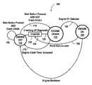
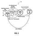
- FIG. 1is a block diagram of a dual-motor, hybrid vehicle powertrain adapted for implementing the present invention
- FIG. 2is a state transition diagram illustrating the method of the present invention
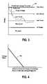
- FIG. 3is a plot illustrating the crank undervoltage threshold of the present invention.
- FIG. 4is a plot of a voltage offset
- FIG. 5is a plot of the voltage offset of FIG. 4 applied to the crank undervoltage threshold of FIG. 3 .
- FIG. 1a block diagram of an exemplary dual-motor, electrically variable transmission powertrain system 1 of a hybrid electric vehicle to which the present invention is applicable is illustrated.
- the powertrain system 1includes a diesel compression ignition engine, a vehicle driveline and a pair of electric machines (also referred to herein as electric motors or motors).
- the motors (identified as A and B), driveline and engineare operatively coupled to one another, for example, through a coupling means (K) comprising one or more planetary gearsets and selective coupling paths established in accordance with application and release of various torque transfer devices, e.g., clutches.
- the engineis coupled ( 11 ) to the coupling means at a mechanical input thereof.
- the drivelineis coupled ( 13 ) to the coupling means at a mechanical output thereof.
- the motorsare coupled ( 15 ) to the coupling means at various rotating members of the planetary gearsets. Neglecting power losses, the power flows between the engine, driveline and motors balance. And, the power at the driveline is equivalent to the summation of the powers at the engine and motors.
- Engine, driveline and motor torquesfollow the same relationships and are known through the various gearsets, power transmission components and the relationships therebetween as embodied in coupling constraint relationships.
- Speed relationships between the engine, driveline and motorare also known through the various gearsets, power transmission components and the relationships therebetween as embodied in coupling constraint relationships.
- the vehicle drivelinemay include such common driveline components as differential gearsets, propshafts, universal joints, final drive gearsets, wheels and tires.
- the electric machinereceives electric power from and provides electric power to an energy storage system (ESS) which may take the form of one or more batteries in a battery pack module or any appropriate energy storage means capable of bidirectional electrical energy flow.
- ESSenergy storage system
- Engine, driveline and motor torquesmay be in either direction. That is to say, each is capable of bidirectional torque contributions to the powertrain.
- An exemplary electrically variable transmissioncomprising a diesel engine, a pair of electric machines and a pair of selectively coupled planetary gearsets and preferred for application of the present control is disclosed in commonly assigned U.S. Pat. No. 5,931,757, the contents of which are incorporated herein by reference.
- HEV EVT powertrain system 1While the invention herein is illustrated with reference to exemplary HEV EVT powertrain system 1 , it is believed to be generally applicable to many HEV powertrain configurations, including those having only one electric machine for cranking the engine, as well as those having more than two electric machines, which may be used separately or in various coupling combinations to crank the engine.
- the exemplary powertrain system 1 of FIG. 1also includes a microprocessor based system controller 43 that communicates with the engine via a conventional microprocessor based engine control module (ECM) 23 .
- the ECM 23preferably communicates with the system controller 43 over a controller area network (CAN) bus.
- the engine controlleris adapted to communicate with various engine actuators and sensors (not separately illustrated) used in the control thereof. For example, fuel injectors, exhaust brake or engine brake actuators and rotation sensors are controlled or monitored by discrete signal lines at the engine controller.
- engine control functions performed by the ECM 23is an engine start function which includes conventional engine fueling routines for providing a fuel charge to engine cylinders during forced rotation of the engine by an electrical machine.
- the system controller 43receives inputs indicative of operator demands including throttle, brake and engine crank.
- the system controller 43communicates with various coupling means actuators and sensors used in the control thereof. For example, output rotation sensors, solenoid control valves for controlling torque transfer device hydraulic pressure and apply/release states thereof, and hydraulic fluid pressure switches or transducers, are controlled or monitored by discrete signal lines.
- the system controller 43also communicates similarly with a microprocessor based battery pack controller and microprocessor based power electronics controller (not separately illustrated), collectively referred to as ESS controllers. These ESS controllers preferably communicate with the system controller 43 over a CAN bus.
- the ESS controllersare adapted to provide a variety of sensing, diagnostic and control functions related to the battery pack and motor.
- the ESS controllersare controlled or monitored by the ESS controllers.
- the engine cranking functionwhich comprises a one sided engine rotation speed control responsive to a crank speed signal effective to rotate, with at least one electric machine, the engine up to the crank speed embodied in the crank speed signal and prevent engine speed from sagging below the crank speed but allowing engine combustion torque to deviate the engine speed from the cranking speed.
- the present inventionrequires that at least one electric machine be operatively coupled to the engine such that the engine can be spun up from a zero speed condition thereby.
- the motormay couple directly to the engine output shaft or may couple thereto via any variety of gearsets (including reduction gearing) or selectively engageable means such as a starting clutch, range clutch or ring and pinion gear arrangement such as a meshingly engaged starter pinion gear and engine flywheel.
- crankingis understood to include forced rotation of the engine such as by an electric machine and engine fueling for combustion torque production.
- the “engine crank” staterefers to an engine state wherein engine cranking occurs by application of an output torque produced by the electric machine.
- the engine crank statealso embodies a method, including a sequence or series of steps, conditions, programs or routines wherein various cranking related diagnostic, control and command functions are performed related to cranking speed, cranking time, the output voltage of the energy storage system, temperature, fueling and other factors by various combinations of the system controller, ECM or other controllers.
- the “engine off” stateis generally characterized by a condition wherein the engine speed is zero and the engine is not being fueled and may also embody a sequence or series of steps, conditions or routines whereby the engine attains or maintains this state.
- the “engine on” staterefers generally to a state wherein sustained engine torque production has been achieved, generally in response to engine fueling and engine cranking.
- the engine on statealso embodies a method, including a sequence or series of steps, conditions, programs or routines wherein various engine operation-related diagnostic, control and command functions are performed related to engine speed, fueling and other factors by various combinations of the system controller, ECM or other controllers.
- the present inventionis described generally with regard to the engine states described above and transitions therefrom.
- the engine statesare represented by circular blocks and the transitions therefrom are represented by arrows.
- the present inventionis a method 100 for controlling the cranking of an engine of a vehicle powertrain system 1 having a rechargeable energy storage system 17 that is adapted to provide electric power to an electric machine 19 for cranking the engine 21 , comprising the steps of: initiating an engine crank state 110 from an engine off state 120 , as illustrated by transition 115 ; controlling an exit 125 from the engine crank state 110 as a function of an output voltage of the energy storage system 17 to the electric machine 19 during the crank state 110 , wherein if the output voltage is less than a crank undervoltage threshold for a predetermined crank time, the crank state 110 is exited and the system transitions from the engine crank state 110 to the engine off state 120 ; incrementing 130 a counter 135 for each such exit 125 from the engine crank state 110 to establish an engine crank count; and if the engine crank count
- method 100may be implemented either in hardware, such as, for example, using various forms of hardwired logic elements, or in software, or in various combinations thereof. However, it is preferred that method 100 comprise a computer control algorithm which may be executed as computer code in one or more computers located in the vehicle, such as found in system controller 43 . The steps of the invention are described in further detail below.
- transition 115the step of initiating an engine crank state 110 from engine off state 120 is illustrated by transition 115 .
- the initiatorwill be a vehicle operator, and initiating 115 will comprise actuation of a start key, push button, knob, lever or other well-known means for actuating a switch.
- the switch actuationwill provide a signal indication to a controller, such as system controller 43 , which is adapted to process the signal and provide the necessary control actions for initiating 115 the transition from engine off state 120 . This may comprise the initialization or start of a software routine or program.
- the enginewill be cranked during crank state 110 in accordance with a method, such as that described above.
- a plurality of control, command and diagnostic routineswill be executed in order to determine whether the system should continue in the engine crank state, or whether the engine start state has been attained, or whether the engine crank state should be exited in favor of the engine off state.
- diagnostic routinesused to test a plurality of system or state parameters, such as the duration of the cranking event, engine speed and the temperature associated with various elements of the system during cranking, to determine whether control commands should be implemented to exit the engine crank state in favor of the engine off state.
- One such diagnosticcomprises method 100 .
- method 100also includes the step of controlling an exit 125 from the engine crank state 110 as a function of an output voltage of the energy storage system 17 to the electric machine 19 during the engine crank state 110 , wherein if the output voltage is less than a crank undervoltage threshold for a predetermined crank time, the crank state 110 is exited and the system transitions from the engine crank state 110 to the engine off state 120 .
- the output voltage of the energy storage systemis preferably monitored continuously during the engine crank state to ascertain the output voltage to the electric machine by one or more controllers, such as system controller 43 .
- the output voltage of the energy storage systemis compared with a crank undervoltage threshold which may be stored in a lookup table, as illustrated in FIG. 3 .
- This cranking undervoltage diagnosticis adapted to force the system out of the cranking state when the output voltage of the ESS drops below the prescribed crank undervoltage threshold during the engine crank state 110 , in order to protect the battery from excessive undervoltage.
- One means for comparing the output voltage of the ESS with the crank undervoltage threshold to determine whether the output voltage is less than the crank undervoltage threshold for a predetermined crank timeis through the use of weighted debouncer logic. This means is utilized so the system can try to crank for a longer time when the voltage is moderately low, but will be forced to exit the engine crank state much more quickly when the voltage is lower.
- Med_Counte.g. 10 counts
- Hi_Counte.g. 50 counts
- the predetermined crank time if the output voltage is within a second range (i.e., defined by the Low_Thresh and Hi_Thresh) using the exemplary values givenis 1 second
- the predetermined crank time if the output voltage is within a third range (i.e., defined by points which are less than the Hi_Thresh) using the exemplary values givenis 0.2 seconds.
- the fail fault of the weighted debouncermay be used to provide an exit signal to the controller to exit the engine crank state if the output voltage is less than the crank undervoltage threshold for a predetermined crank time.
- the predetermined crank timemay be determined as a function of the magnitude of the difference between the output voltage and the crank undervoltage threshold, as illustrated in FIG. 3 .
- the magnitude of the differencemay be defined by a plurality of thresholds, or ranges, as in the example described above and illustrated in FIG. 3 , or it may be defined by taking the difference of the output voltage and the threshold directly. Further, as the magnitude of the difference increases, the predetermined crank time decreases.
- This diagnosticalso accepts a crank undervoltage offset 145 value as illustrated in FIG. 4 .
- This inputshifts the crank undervoltage threshold 147 as well as any additional thresholds or ranges (i.e., Zero_Thresh, Low_Thresh, Hi_Thresh) in an additive manner to allow for different fault voltage levels in certain states, as illustrated in FIG. 5 .
- the offset 145is determined based on the number of exits from the engine crank state to the engine off state, such that the crank undervoltage offset 145 value decreases with the number of exits.
- crank undervoltage threshold 147is a function of the number of exits from the engine crank state to the engine off state due to the diagnostic, preferably a generally decreasing function.
- Method 100also includes a step of incrementing 130 a counter 135 for each such exit 125 from the engine crank state 110 to establish an engine crank count.
- the step of incrementing 130 a counter 135should be understood broadly to include all manner of implementing a means of obtaining a count of the transitions between states comprising known techniques for incrementing and decrementing a counter 135 to obtain a count of such transitions.
- Method 100also includes a looping mechanism, such that if the engine crank count does not exceed an engine crank count limit, method 100 includes a step of repeating 140 the preceding steps of the method.
- the engine crank count limitis the maximum number of exits 125 from the engine crank state to the engine off state permitted due to the diagnostic.
- Method 100may also include an additional level of protection in response to extreme undervoltage situations, particularly where the crank undervoltage diagnostic has executed as described herein and the engine crank count limit has been exceeded (i.e., the maximum number of attempts to start the engine have been utilized), wherein if the engine crank count exceeds the engine crank count limit, method 100 includes setting a crank count limit or inhibit fault in the system which disallows subsequent initiating of the engine crank state until the fault is cleared. Such a fault may be utilized to lock out the energy storage system from further utilization and potential damage of the battery pack due to extreme undervoltage conditions. Referring to FIG.
- the systemwill execute the action represented by transition 155 , wherein there is no change in state.
- the faultmay be set such that it may only be cleared by trained service personnel using a service tool that is adapted to clear the fault. Once the maximum number of exits from the engine start state to the engine off state has been exceeded, the service tool must be used to reset the fault and re-enable cranking. The service technician will be given one start attempt and one additional execution of method 100 .
- crank undervoltage diagnosticIf the vehicle does not transition to the engine on state 150 and the engine start does not occur, the system exits according to the crank undervoltage diagnostic from the engine crank state to the engine off state, the crank count limit or inhibit fault occurs again because the maximum number of exits has been exceeded, and the fault will again have to be reset from the service tool for subsequent start attempts.
- the cranking undervoltage diagnosticwill remain be active as described however, to protect the batteries from complete discharge.
- transition 160it is generally preferable to incorporate a step of resetting 165 counter 135 , as the energy storage system will, in all probability, be recharged sufficiently to alleviate any concerns about battery undervoltage during this state.
- Resetting 160may be done immediately upon attaining engine on state 150 , or may also be subject to various verification tests, delays, diagnostic routines or other means of insuring that the engine on state has been successfully attained prior to resetting 165 counter 135 .
- transitionsare possible between various engine states, particularly between engine crank state 110 and engine off state 120 , such as a transition 175 due to the engine cranking time exceeding a cranking limit, which may be implemented in conjunction with transition 115 in accordance with method 100 .
- the methodmay also incorporate a step of providing 160 an indication of the exit crank count.
- the countmay be utilized in conjunction with the controller to provide all manner of indications of the exit crank count, such as indications that may be sensed by an operator, and may include all manner of well-known audible indications, such as a bell, horn, or other audible indication, visual indications, such as a graphic display, counter or other well-known visual indications, as well as a tactile indication, such as vibrating the start actuator, or altering its response characteristics.
Landscapes
- Engineering & Computer Science (AREA)
- Chemical & Material Sciences (AREA)
- Combustion & Propulsion (AREA)
- Mechanical Engineering (AREA)
- Transportation (AREA)
- General Engineering & Computer Science (AREA)
- Automation & Control Theory (AREA)
- Combined Controls Of Internal Combustion Engines (AREA)
- Control Of Vehicle Engines Or Engines For Specific Uses (AREA)
- Output Control And Ontrol Of Special Type Engine (AREA)
Abstract
Description
Claims (20)
Priority Applications (3)
| Application Number | Priority Date | Filing Date | Title |
|---|---|---|---|
| US10/845,999US7277781B2 (en) | 2004-05-14 | 2004-05-14 | Method of undervoltage protection during engine cranking |
| DE102005021250ADE102005021250B4 (en) | 2004-05-14 | 2005-05-09 | Method for undervoltage protection during engine starting |
| CNB2005100712153ACN100383688C (en) | 2004-05-14 | 2005-05-13 | Method of controlling engine starting in a vehicle powertrain |
Applications Claiming Priority (1)
| Application Number | Priority Date | Filing Date | Title |
|---|---|---|---|
| US10/845,999US7277781B2 (en) | 2004-05-14 | 2004-05-14 | Method of undervoltage protection during engine cranking |
Publications (2)
| Publication Number | Publication Date |
|---|---|
| US20050256617A1 US20050256617A1 (en) | 2005-11-17 |
| US7277781B2true US7277781B2 (en) | 2007-10-02 |
Family
ID=35310432
Family Applications (1)
| Application Number | Title | Priority Date | Filing Date |
|---|---|---|---|
| US10/845,999Expired - LifetimeUS7277781B2 (en) | 2004-05-14 | 2004-05-14 | Method of undervoltage protection during engine cranking |
Country Status (3)
| Country | Link |
|---|---|
| US (1) | US7277781B2 (en) |
| CN (1) | CN100383688C (en) |
| DE (1) | DE102005021250B4 (en) |
Cited By (5)
| Publication number | Priority date | Publication date | Assignee | Title |
|---|---|---|---|---|
| US20090174362A1 (en)* | 2008-01-03 | 2009-07-09 | F.D. Richardson Enterprises, Inc. Doing Business As Richardson Jumpstarters | Method and apparatus for providing supplemental power to an engine |
| US20090218988A1 (en)* | 2008-01-03 | 2009-09-03 | Richardson Francis D | Method and apparatus for providing supplemental power to an engine |
| US20100181959A1 (en)* | 2009-01-19 | 2010-07-22 | Gm Global Technology Operations, Inc. | Method and system for internally jump-starting an engine |
| US20130261859A1 (en)* | 2012-03-28 | 2013-10-03 | Toyota Jidosha Kabushiki Kaisha | Hybrid vehicle |
| US10259443B2 (en) | 2013-10-18 | 2019-04-16 | Ford Global Technologies, Llc | Hybrid-electric vehicle plug-out mode energy management |
Families Citing this family (213)
| Publication number | Priority date | Publication date | Assignee | Title |
|---|---|---|---|---|
| US8872517B2 (en) | 1996-07-29 | 2014-10-28 | Midtronics, Inc. | Electronic battery tester with battery age input |
| US6566883B1 (en) | 1999-11-01 | 2003-05-20 | Midtronics, Inc. | Electronic battery tester |
| US6850037B2 (en) | 1997-11-03 | 2005-02-01 | Midtronics, Inc. | In-vehicle battery monitor |
| US7706991B2 (en) | 1996-07-29 | 2010-04-27 | Midtronics, Inc. | Alternator tester |
| US8198900B2 (en) | 1996-07-29 | 2012-06-12 | Midtronics, Inc. | Automotive battery charging system tester |
| US7688074B2 (en) | 1997-11-03 | 2010-03-30 | Midtronics, Inc. | Energy management system for automotive vehicle |
| US7705602B2 (en) | 1997-11-03 | 2010-04-27 | Midtronics, Inc. | Automotive vehicle electrical system diagnostic device |
| US8958998B2 (en) | 1997-11-03 | 2015-02-17 | Midtronics, Inc. | Electronic battery tester with network communication |
| US7774151B2 (en) | 1997-11-03 | 2010-08-10 | Midtronics, Inc. | Wireless battery monitor |
| US7126341B2 (en) | 1997-11-03 | 2006-10-24 | Midtronics, Inc. | Automotive vehicle electrical system diagnostic device |
| US7446536B2 (en) | 2000-03-27 | 2008-11-04 | Midtronics, Inc. | Scan tool for electronic battery tester |
| US7598743B2 (en)* | 2000-03-27 | 2009-10-06 | Midtronics, Inc. | Battery maintenance device having databus connection |
| US7598744B2 (en) | 2000-03-27 | 2009-10-06 | Midtronics, Inc. | Scan tool for electronic battery tester |
| US8513949B2 (en) | 2000-03-27 | 2013-08-20 | Midtronics, Inc. | Electronic battery tester or charger with databus connection |
| US7398176B2 (en) | 2000-03-27 | 2008-07-08 | Midtronics, Inc. | Battery testers with secondary functionality |
| US9018958B2 (en) | 2003-09-05 | 2015-04-28 | Midtronics, Inc. | Method and apparatus for measuring a parameter of a vehicle electrical system |
| US9255955B2 (en) | 2003-09-05 | 2016-02-09 | Midtronics, Inc. | Method and apparatus for measuring a parameter of a vehicle electrical system |
| US8164343B2 (en) | 2003-09-05 | 2012-04-24 | Midtronics, Inc. | Method and apparatus for measuring a parameter of a vehicle electrical system |
| US7154276B2 (en) | 2003-09-05 | 2006-12-26 | Midtronics, Inc. | Method and apparatus for measuring a parameter of a vehicle electrical system |
| US7977914B2 (en) | 2003-10-08 | 2011-07-12 | Midtronics, Inc. | Battery maintenance tool with probe light |
| US7777612B2 (en) | 2004-04-13 | 2010-08-17 | Midtronics, Inc. | Theft prevention device for automotive vehicle service centers |
| US7772850B2 (en) | 2004-07-12 | 2010-08-10 | Midtronics, Inc. | Wireless battery tester with information encryption means |
| US7106070B2 (en) | 2004-07-22 | 2006-09-12 | Midtronics, Inc. | Broad-band low-inductance cables for making Kelvin connections to electrochemical cells and batteries |
| US8436619B2 (en) | 2004-08-20 | 2013-05-07 | Midtronics, Inc. | Integrated tag reader and environment sensor |
| US8344685B2 (en) | 2004-08-20 | 2013-01-01 | Midtronics, Inc. | System for automatically gathering battery information |
| US9496720B2 (en) | 2004-08-20 | 2016-11-15 | Midtronics, Inc. | System for automatically gathering battery information |
| US8442877B2 (en) | 2004-08-20 | 2013-05-14 | Midtronics, Inc. | Simplification of inventory management |
| US7710119B2 (en) | 2004-12-09 | 2010-05-04 | Midtronics, Inc. | Battery tester that calculates its own reference values |
| US8010263B2 (en)* | 2006-03-22 | 2011-08-30 | GM Global Technology Operations LLC | Method and apparatus for multivariate active driveline damping |
| US8091667B2 (en)* | 2006-06-07 | 2012-01-10 | GM Global Technology Operations LLC | Method for operating a hybrid electric powertrain based on predictive effects upon an electrical energy storage device |
| US7791348B2 (en) | 2007-02-27 | 2010-09-07 | Midtronics, Inc. | Battery tester with promotion feature to promote use of the battery tester by providing the user with codes having redeemable value |
| US7987934B2 (en) | 2007-03-29 | 2011-08-02 | GM Global Technology Operations LLC | Method for controlling engine speed in a hybrid electric vehicle |
| US7808375B2 (en) | 2007-04-16 | 2010-10-05 | Midtronics, Inc. | Battery run down indicator |
| US7999496B2 (en)* | 2007-05-03 | 2011-08-16 | GM Global Technology Operations LLC | Method and apparatus to determine rotational position of an electrical machine |
| US7996145B2 (en) | 2007-05-03 | 2011-08-09 | GM Global Technology Operations LLC | Method and apparatus to control engine restart for a hybrid powertrain system |
| US7991519B2 (en) | 2007-05-14 | 2011-08-02 | GM Global Technology Operations LLC | Control architecture and method to evaluate engine off operation of a hybrid powertrain system operating in a continuously variable mode |
| US9274157B2 (en) | 2007-07-17 | 2016-03-01 | Midtronics, Inc. | Battery tester for electric vehicle |
| GB2463829B (en) | 2007-07-17 | 2012-11-21 | Midtronics Inc | Battery tester for electric vehicle |
| US8390240B2 (en) | 2007-08-06 | 2013-03-05 | GM Global Technology Operations LLC | Absolute position sensor for field-oriented control of an induction motor |
| US7983823B2 (en) | 2007-09-11 | 2011-07-19 | GM Global Technology Operations LLC | Method and control architecture for selection of optimal engine input torque for a powertrain system |
| US8265813B2 (en)* | 2007-09-11 | 2012-09-11 | GM Global Technology Operations LLC | Method and control architecture for optimization of engine fuel-cutoff selection and engine input torque for a hybrid powertrain system |
| US7988591B2 (en)* | 2007-09-11 | 2011-08-02 | GM Global Technology Operations LLC | Control architecture and method for one-dimensional optimization of input torque and motor torque in fixed gear for a hybrid powertrain system |
| US8027771B2 (en)* | 2007-09-13 | 2011-09-27 | GM Global Technology Operations LLC | Method and apparatus to monitor an output speed sensor during operation of an electro-mechanical transmission |
| US7867135B2 (en) | 2007-09-26 | 2011-01-11 | GM Global Technology Operations LLC | Electro-mechanical transmission control system |
| US8062170B2 (en)* | 2007-09-28 | 2011-11-22 | GM Global Technology Operations LLC | Thermal protection of an electric drive system |
| US8234048B2 (en) | 2007-10-19 | 2012-07-31 | GM Global Technology Operations LLC | Method and system for inhibiting operation in a commanded operating range state for a transmission of a powertrain system |
| US8060267B2 (en) | 2007-10-23 | 2011-11-15 | GM Global Technology Operations LLC | Method for controlling power flow within a powertrain system |
| US9140337B2 (en) | 2007-10-23 | 2015-09-22 | GM Global Technology Operations LLC | Method for model based clutch control and torque estimation |
| US8118122B2 (en) | 2007-10-25 | 2012-02-21 | GM Global Technology Operations LLC | Method and system for monitoring signal integrity in a distributed controls system |
| US8296027B2 (en) | 2007-10-25 | 2012-10-23 | GM Global Technology Operations LLC | Method and apparatus to control off-going clutch torque during torque phase for a hybrid powertrain system |
| US8335623B2 (en) | 2007-10-25 | 2012-12-18 | GM Global Technology Operations LLC | Method and apparatus for remediation of and recovery from a clutch slip event in a hybrid powertrain system |
| US8187145B2 (en) | 2007-10-25 | 2012-05-29 | GM Global Technology Operations LLC | Method and apparatus for clutch torque control in mode and fixed gear for a hybrid powertrain system |
| US8265821B2 (en) | 2007-10-25 | 2012-09-11 | GM Global Technology Operations LLC | Method for determining a voltage level across an electric circuit of a powertrain |
| US8204702B2 (en) | 2007-10-26 | 2012-06-19 | GM Global Technology Operations LLC | Method for estimating battery life in a hybrid powertrain |
| US9097337B2 (en) | 2007-10-26 | 2015-08-04 | GM Global Technology Operations LLC | Method and apparatus to control hydraulic line pressure in an electro-mechanical transmission |
| US8406945B2 (en) | 2007-10-26 | 2013-03-26 | GM Global Technology Operations LLC | Method and apparatus to control logic valves for hydraulic flow control in an electro-mechanical transmission |
| US8560191B2 (en) | 2007-10-26 | 2013-10-15 | GM Global Technology Operations LLC | Method and apparatus to control clutch pressures in an electro-mechanical transmission |
| US8303463B2 (en) | 2007-10-26 | 2012-11-06 | GM Global Technology Operations LLC | Method and apparatus to control clutch fill pressure in an electro-mechanical transmission |
| US7985154B2 (en) | 2007-10-26 | 2011-07-26 | GM Global Technology Operations LLC | Method and apparatus to control hydraulic pressure for component lubrication in an electro-mechanical transmission |
| US8548703B2 (en) | 2007-10-26 | 2013-10-01 | GM Global Technology Operations LLC | Method and apparatus to determine clutch slippage in an electro-mechanical transmission |
| US8167773B2 (en) | 2007-10-26 | 2012-05-01 | GM Global Technology Operations LLC | Method and apparatus to control motor cooling in an electro-mechanical transmission |
| US8428816B2 (en) | 2007-10-27 | 2013-04-23 | GM Global Technology Operations LLC | Method and apparatus for monitoring software and signal integrity in a distributed control module system for a powertrain system |
| US8062174B2 (en) | 2007-10-27 | 2011-11-22 | GM Global Technology Operations LLC | Method and apparatus to control clutch stroke volume in an electro-mechanical transmission |
| US8244426B2 (en) | 2007-10-27 | 2012-08-14 | GM Global Technology Operations LLC | Method and apparatus for monitoring processor integrity in a distributed control module system for a powertrain system |
| US8099219B2 (en) | 2007-10-27 | 2012-01-17 | GM Global Technology Operations LLC | Method and apparatus for securing an operating range state mechanical transmission |
| US8282526B2 (en) | 2007-10-29 | 2012-10-09 | GM Global Technology Operations LLC | Method and apparatus to create a pseudo torque phase during oncoming clutch engagement to prevent clutch slip for a hybrid powertrain system |
| US8170762B2 (en) | 2007-10-29 | 2012-05-01 | GM Global Technology Operations LLC | Method and apparatus to control operation of a hydraulic pump for an electro-mechanical transmission |
| US8095254B2 (en) | 2007-10-29 | 2012-01-10 | GM Global Technology Operations LLC | Method for determining a power constraint for controlling a powertrain system |
| US8112194B2 (en) | 2007-10-29 | 2012-02-07 | GM Global Technology Operations LLC | Method and apparatus for monitoring regenerative operation in a hybrid powertrain system |
| US8290681B2 (en) | 2007-10-29 | 2012-10-16 | GM Global Technology Operations LLC | Method and apparatus to produce a smooth input speed profile in mode for a hybrid powertrain system |
| US8489293B2 (en) | 2007-10-29 | 2013-07-16 | GM Global Technology Operations LLC | Method and apparatus to control input speed profile during inertia speed phase for a hybrid powertrain system |
| US8209098B2 (en) | 2007-10-29 | 2012-06-26 | GM Global Technology Operations LLC | Method and apparatus for monitoring a transmission range selector in a hybrid powertrain transmission |
| US8078371B2 (en) | 2007-10-31 | 2011-12-13 | GM Global Technology Operations LLC | Method and apparatus to monitor output of an electro-mechanical transmission |
| US8073602B2 (en) | 2007-11-01 | 2011-12-06 | GM Global Technology Operations LLC | System constraints method of controlling operation of an electro-mechanical transmission with an additional constraint range |
| US8035324B2 (en) | 2007-11-01 | 2011-10-11 | GM Global Technology Operations LLC | Method for determining an achievable torque operating region for a transmission |
| US8145375B2 (en) | 2007-11-01 | 2012-03-27 | GM Global Technology Operations LLC | System constraints method of determining minimum and maximum torque limits for an electro-mechanical powertrain system |
| US8556011B2 (en) | 2007-11-01 | 2013-10-15 | GM Global Technology Operations LLC | Prediction strategy for thermal management and protection of power electronic hardware |
| US7977896B2 (en) | 2007-11-01 | 2011-07-12 | GM Global Technology Operations LLC | Method of determining torque limit with motor torque and battery power constraints |
| US8287426B2 (en) | 2007-11-02 | 2012-10-16 | GM Global Technology Operations LLC | Method for controlling voltage within a powertrain system |
| US8200403B2 (en) | 2007-11-02 | 2012-06-12 | GM Global Technology Operations LLC | Method for controlling input torque provided to a transmission |
| US8121767B2 (en) | 2007-11-02 | 2012-02-21 | GM Global Technology Operations LLC | Predicted and immediate output torque control architecture for a hybrid powertrain system |
| US8131437B2 (en) | 2007-11-02 | 2012-03-06 | GM Global Technology Operations LLC | Method for operating a powertrain system to transition between engine states |
| US8224539B2 (en) | 2007-11-02 | 2012-07-17 | GM Global Technology Operations LLC | Method for altitude-compensated transmission shift scheduling |
| US8121765B2 (en) | 2007-11-02 | 2012-02-21 | GM Global Technology Operations LLC | System constraints method of controlling operation of an electro-mechanical transmission with two external input torque ranges |
| US8847426B2 (en) | 2007-11-02 | 2014-09-30 | GM Global Technology Operations LLC | Method for managing electric power in a powertrain system |
| US8133151B2 (en) | 2007-11-02 | 2012-03-13 | GM Global Technology Operations LLC | System constraints method of controlling operation of an electro-mechanical transmission with an additional constraint |
| US8170764B2 (en) | 2007-11-02 | 2012-05-01 | GM Global Technology Operations LLC | Method and apparatus to reprofile input speed during speed during speed phase during constrained conditions for a hybrid powertrain system |
| US8585540B2 (en) | 2007-11-02 | 2013-11-19 | GM Global Technology Operations LLC | Control system for engine torque management for a hybrid powertrain system |
| US8825320B2 (en) | 2007-11-02 | 2014-09-02 | GM Global Technology Operations LLC | Method and apparatus for developing a deceleration-based synchronous shift schedule |
| US8285431B2 (en) | 2007-11-03 | 2012-10-09 | GM Global Technology Operations LLC | Optimal selection of hybrid range state and/or input speed with a blended braking system in a hybrid electric vehicle |
| US8296021B2 (en) | 2007-11-03 | 2012-10-23 | GM Global Technology Operations LLC | Method for determining constraints on input torque in a hybrid transmission |
| US8010247B2 (en) | 2007-11-03 | 2011-08-30 | GM Global Technology Operations LLC | Method for operating an engine in a hybrid powertrain system |
| US8068966B2 (en) | 2007-11-03 | 2011-11-29 | GM Global Technology Operations LLC | Method for monitoring an auxiliary pump for a hybrid powertrain |
| US8224514B2 (en) | 2007-11-03 | 2012-07-17 | GM Global Technology Operations LLC | Creation and depletion of short term power capability in a hybrid electric vehicle |
| US8155814B2 (en) | 2007-11-03 | 2012-04-10 | GM Global Technology Operations LLC | Method of operating a vehicle utilizing regenerative braking |
| US8135526B2 (en) | 2007-11-03 | 2012-03-13 | GM Global Technology Operations LLC | Method for controlling regenerative braking and friction braking |
| US8204664B2 (en) | 2007-11-03 | 2012-06-19 | GM Global Technology Operations LLC | Method for controlling regenerative braking in a vehicle |
| US8002667B2 (en) | 2007-11-03 | 2011-08-23 | GM Global Technology Operations LLC | Method for determining input speed acceleration limits in a hybrid transmission |
| US8260511B2 (en) | 2007-11-03 | 2012-09-04 | GM Global Technology Operations LLC | Method for stabilization of mode and fixed gear for a hybrid powertrain system |
| US8868252B2 (en) | 2007-11-03 | 2014-10-21 | GM Global Technology Operations LLC | Control architecture and method for two-dimensional optimization of input speed and input power including search windowing |
| US8406970B2 (en) | 2007-11-03 | 2013-03-26 | GM Global Technology Operations LLC | Method for stabilization of optimal input speed in mode for a hybrid powertrain system |
| US8204656B2 (en) | 2007-11-04 | 2012-06-19 | GM Global Technology Operations LLC | Control architecture for output torque shaping and motor torque determination for a hybrid powertrain system |
| US8138703B2 (en) | 2007-11-04 | 2012-03-20 | GM Global Technology Operations LLC | Method and apparatus for constraining output torque in a hybrid powertrain system |
| US8126624B2 (en) | 2007-11-04 | 2012-02-28 | GM Global Technology Operations LLC | Method for selection of optimal mode and gear and input speed for preselect or tap up/down operation |
| US8214093B2 (en) | 2007-11-04 | 2012-07-03 | GM Global Technology Operations LLC | Method and apparatus to prioritize transmission output torque and input acceleration for a hybrid powertrain system |
| US8092339B2 (en) | 2007-11-04 | 2012-01-10 | GM Global Technology Operations LLC | Method and apparatus to prioritize input acceleration and clutch synchronization performance in neutral for a hybrid powertrain system |
| US8818660B2 (en) | 2007-11-04 | 2014-08-26 | GM Global Technology Operations LLC | Method for managing lash in a driveline |
| US8214120B2 (en) | 2007-11-04 | 2012-07-03 | GM Global Technology Operations LLC | Method to manage a high voltage system in a hybrid powertrain system |
| US8112206B2 (en) | 2007-11-04 | 2012-02-07 | GM Global Technology Operations LLC | Method for controlling a powertrain system based upon energy storage device temperature |
| US8079933B2 (en) | 2007-11-04 | 2011-12-20 | GM Global Technology Operations LLC | Method and apparatus to control engine torque to peak main pressure for a hybrid powertrain system |
| US8118903B2 (en) | 2007-11-04 | 2012-02-21 | GM Global Technology Operations LLC | Method for preferential selection of modes and gear with inertia effects for a hybrid powertrain system |
| US8897975B2 (en) | 2007-11-04 | 2014-11-25 | GM Global Technology Operations LLC | Method for controlling a powertrain system based on penalty costs |
| US8200383B2 (en) | 2007-11-04 | 2012-06-12 | GM Global Technology Operations LLC | Method for controlling a powertrain system based upon torque machine temperature |
| US8248023B2 (en) | 2007-11-04 | 2012-08-21 | GM Global Technology Operations LLC | Method of externally charging a powertrain |
| US8504259B2 (en) | 2007-11-04 | 2013-08-06 | GM Global Technology Operations LLC | Method for determining inertia effects for a hybrid powertrain system |
| US8135532B2 (en) | 2007-11-04 | 2012-03-13 | GM Global Technology Operations LLC | Method for controlling output power of an energy storage device in a powertrain system |
| US8214114B2 (en) | 2007-11-04 | 2012-07-03 | GM Global Technology Operations LLC | Control of engine torque for traction and stability control events for a hybrid powertrain system |
| US8221285B2 (en) | 2007-11-04 | 2012-07-17 | GM Global Technology Operations LLC | Method and apparatus to offload offgoing clutch torque with asynchronous oncoming clutch torque, engine and motor torque for a hybrid powertrain system |
| US8346449B2 (en) | 2007-11-04 | 2013-01-01 | GM Global Technology Operations LLC | Method and apparatus to provide necessary output torque reserve by selection of hybrid range state and input speed for a hybrid powertrain system |
| US8098041B2 (en) | 2007-11-04 | 2012-01-17 | GM Global Technology Operations LLC | Method of charging a powertrain |
| US8121766B2 (en) | 2007-11-04 | 2012-02-21 | GM Global Technology Operations LLC | Method for operating an internal combustion engine to transmit power to a driveline |
| US8112192B2 (en) | 2007-11-04 | 2012-02-07 | GM Global Technology Operations LLC | Method for managing electric power within a powertrain system |
| US8494732B2 (en) | 2007-11-04 | 2013-07-23 | GM Global Technology Operations LLC | Method for determining a preferred engine operation in a hybrid powertrain system during blended braking |
| US8067908B2 (en) | 2007-11-04 | 2011-11-29 | GM Global Technology Operations LLC | Method for electric power boosting in a powertrain system |
| US8095282B2 (en) | 2007-11-04 | 2012-01-10 | GM Global Technology Operations LLC | Method and apparatus for soft costing input speed and output speed in mode and fixed gear as function of system temperatures for cold and hot operation for a hybrid powertrain system |
| US8000866B2 (en) | 2007-11-04 | 2011-08-16 | GM Global Technology Operations LLC | Engine control system for torque management in a hybrid powertrain system |
| US8374758B2 (en) | 2007-11-04 | 2013-02-12 | GM Global Technology Operations LLC | Method for developing a trip cost structure to understand input speed trip for a hybrid powertrain system |
| US8396634B2 (en) | 2007-11-04 | 2013-03-12 | GM Global Technology Operations LLC | Method and apparatus for maximum and minimum output torque performance by selection of hybrid range state and input speed for a hybrid powertrain system |
| US8145397B2 (en) | 2007-11-04 | 2012-03-27 | GM Global Technology Operations LLC | Optimal selection of blended braking capacity for a hybrid electric vehicle |
| US9008926B2 (en) | 2007-11-04 | 2015-04-14 | GM Global Technology Operations LLC | Control of engine torque during upshift and downshift torque phase for a hybrid powertrain system |
| US8002665B2 (en) | 2007-11-04 | 2011-08-23 | GM Global Technology Operations LLC | Method for controlling power actuators in a hybrid powertrain system |
| US8630776B2 (en) | 2007-11-04 | 2014-01-14 | GM Global Technology Operations LLC | Method for controlling an engine of a hybrid powertrain in a fuel enrichment mode |
| US8594867B2 (en) | 2007-11-04 | 2013-11-26 | GM Global Technology Operations LLC | System architecture for a blended braking system in a hybrid powertrain system |
| US8414449B2 (en) | 2007-11-04 | 2013-04-09 | GM Global Technology Operations LLC | Method and apparatus to perform asynchronous shifts with oncoming slipping clutch torque for a hybrid powertrain system |
| US7988594B2 (en) | 2007-11-04 | 2011-08-02 | GM Global Technology Operations LLC | Method for load-based stabilization of mode and fixed gear operation of a hybrid powertrain system |
| US8135519B2 (en) | 2007-11-05 | 2012-03-13 | GM Global Technology Operations LLC | Method and apparatus to determine a preferred output torque for operating a hybrid transmission in a fixed gear operating range state |
| US8112207B2 (en) | 2007-11-05 | 2012-02-07 | GM Global Technology Operations LLC | Method and apparatus to determine a preferred output torque for operating a hybrid transmission in a continuously variable mode |
| US8155815B2 (en) | 2007-11-05 | 2012-04-10 | Gm Global Technology Operation Llc | Method and apparatus for securing output torque in a distributed control module system for a powertrain system |
| US8160761B2 (en) | 2007-11-05 | 2012-04-17 | GM Global Technology Operations LLC | Method for predicting an operator torque request of a hybrid powertrain system |
| US8321100B2 (en) | 2007-11-05 | 2012-11-27 | GM Global Technology Operations LLC | Method and apparatus for dynamic output torque limiting for a hybrid powertrain system |
| US8099204B2 (en)* | 2007-11-05 | 2012-01-17 | GM Global Technology Operatons LLC | Method for controlling electric boost in a hybrid powertrain |
| US8285462B2 (en) | 2007-11-05 | 2012-10-09 | GM Global Technology Operations LLC | Method and apparatus to determine a preferred output torque in mode and fixed gear operation with clutch torque constraints for a hybrid powertrain system |
| US8285432B2 (en) | 2007-11-05 | 2012-10-09 | GM Global Technology Operations LLC | Method and apparatus for developing a control architecture for coordinating shift execution and engine torque control |
| US8165777B2 (en) | 2007-11-05 | 2012-04-24 | GM Global Technology Operations LLC | Method to compensate for transmission spin loss for a hybrid powertrain system |
| US8219303B2 (en) | 2007-11-05 | 2012-07-10 | GM Global Technology Operations LLC | Method for operating an internal combustion engine for a hybrid powertrain system |
| US8073601B2 (en) | 2007-11-05 | 2011-12-06 | GM Global Technology Operations LLC | Method for preferential selection of mode and gear and input speed based on multiple engine state fueling costs for a hybrid powertrain system |
| US8448731B2 (en) | 2007-11-05 | 2013-05-28 | GM Global Technology Operations LLC | Method and apparatus for determination of fast actuating engine torque for a hybrid powertrain system |
| US8249766B2 (en) | 2007-11-05 | 2012-08-21 | GM Global Technology Operations LLC | Method of determining output torque limits of a hybrid transmission operating in a fixed gear operating range state |
| US8229633B2 (en) | 2007-11-05 | 2012-07-24 | GM Global Technology Operations LLC | Method for operating a powertrain system to control engine stabilization |
| US8070647B2 (en) | 2007-11-05 | 2011-12-06 | GM Global Technology Operations LLC | Method and apparatus for adapting engine operation in a hybrid powertrain system for active driveline damping |
| US8121768B2 (en) | 2007-11-05 | 2012-02-21 | GM Global Technology Operations LLC | Method for controlling a hybrid powertrain system based upon hydraulic pressure and clutch reactive torque capacity |
| US8281885B2 (en) | 2007-11-06 | 2012-10-09 | GM Global Technology Operations LLC | Method and apparatus to monitor rotational speeds in an electro-mechanical transmission |
| US8179127B2 (en) | 2007-11-06 | 2012-05-15 | GM Global Technology Operations LLC | Method and apparatus to monitor position of a rotatable shaft |
| US8433486B2 (en) | 2007-11-07 | 2013-04-30 | GM Global Technology Operations LLC | Method and apparatus to determine a preferred operating point for an engine of a powertrain system using an iterative search |
| US8271173B2 (en) | 2007-11-07 | 2012-09-18 | GM Global Technology Operations LLC | Method and apparatus for controlling a hybrid powertrain system |
| US8224544B2 (en)* | 2007-11-07 | 2012-07-17 | GM Global Technology Operations LLC | Method and apparatus to control launch of a vehicle having an electro-mechanical transmission |
| US8209097B2 (en) | 2007-11-07 | 2012-06-26 | GM Global Technology Operations LLC | Method and control architecture to determine motor torque split in fixed gear operation for a hybrid powertrain system |
| US8073610B2 (en) | 2007-11-07 | 2011-12-06 | GM Global Technology Operations LLC | Method and apparatus to control warm-up of an exhaust aftertreatment system for a hybrid powertrain |
| US8277363B2 (en) | 2007-11-07 | 2012-10-02 | GM Global Technology Operations LLC | Method and apparatus to control temperature of an exhaust aftertreatment system for a hybrid powertrain |
| US8195349B2 (en) | 2007-11-07 | 2012-06-05 | GM Global Technology Operations LLC | Method for predicting a speed output of a hybrid powertrain system |
| US8267837B2 (en) | 2007-11-07 | 2012-09-18 | GM Global Technology Operations LLC | Method and apparatus to control engine temperature for a hybrid powertrain |
| US8005632B2 (en)* | 2007-11-07 | 2011-08-23 | GM Global Technology Operations LLC | Method and apparatus for detecting faults in a current sensing device |
| US8203345B2 (en) | 2007-12-06 | 2012-06-19 | Midtronics, Inc. | Storage battery and battery tester |
| HUP0800048A2 (en)* | 2008-01-25 | 2009-08-28 | Istvan Dr Janosi | Frying device for making fried cake specially for household |
| DE102008009568A1 (en)* | 2008-02-16 | 2009-08-20 | Bayerische Motoren Werke Aktiengesellschaft | Energy supply device for a hybrid vehicle and method for operating a high-voltage electrical energy storage device |
| CN102035048B (en)* | 2009-09-27 | 2013-03-20 | 苏州益高电动车辆制造有限公司 | Storage battery protector |
| US9588185B2 (en) | 2010-02-25 | 2017-03-07 | Keith S. Champlin | Method and apparatus for detecting cell deterioration in an electrochemical cell or battery |
| WO2011109343A2 (en) | 2010-03-03 | 2011-09-09 | Midtronics, Inc. | Monitor for front terminal batteries |
| US9229062B2 (en) | 2010-05-27 | 2016-01-05 | Midtronics, Inc. | Electronic storage battery diagnostic system |
| US8738309B2 (en) | 2010-09-30 | 2014-05-27 | Midtronics, Inc. | Battery pack maintenance for electric vehicles |
| US20110300416A1 (en) | 2010-06-03 | 2011-12-08 | Bertness Kevin I | Battery pack maintenance for electric vehicle |
| US11740294B2 (en) | 2010-06-03 | 2023-08-29 | Midtronics, Inc. | High use battery pack maintenance |
| US10046649B2 (en) | 2012-06-28 | 2018-08-14 | Midtronics, Inc. | Hybrid and electric vehicle battery pack maintenance device |
| US9419311B2 (en) | 2010-06-18 | 2016-08-16 | Midtronics, Inc. | Battery maintenance device with thermal buffer |
| US9201120B2 (en) | 2010-08-12 | 2015-12-01 | Midtronics, Inc. | Electronic battery tester for testing storage battery |
| DE102010041921A1 (en)* | 2010-10-04 | 2012-04-05 | Ford Global Technologies, Llc | Method and arrangement for determining the starting capability of a starter battery of an internal combustion engine in the stop-start mode |
| CN102305887B (en)* | 2011-06-03 | 2013-08-21 | 湛江高压电器有限公司 | Discharging current counter |
| US8827865B2 (en) | 2011-08-31 | 2014-09-09 | GM Global Technology Operations LLC | Control system for a hybrid powertrain system |
| WO2013070850A2 (en) | 2011-11-10 | 2013-05-16 | Midtronics, Inc. | Battery pack tester |
| US8801567B2 (en) | 2012-02-17 | 2014-08-12 | GM Global Technology Operations LLC | Method and apparatus for executing an asynchronous clutch-to-clutch shift in a hybrid transmission |
| FR2991731B1 (en)* | 2012-06-08 | 2014-05-23 | Renault Sa | METHOD FOR STARTING A THERMAL MOTOR, SYSTEM AND COMPUTER THEREFOR |
| US11325479B2 (en) | 2012-06-28 | 2022-05-10 | Midtronics, Inc. | Hybrid and electric vehicle battery maintenance device |
| US9851411B2 (en) | 2012-06-28 | 2017-12-26 | Keith S. Champlin | Suppressing HF cable oscillations during dynamic measurements of cells and batteries |
| CN103066569B (en)* | 2012-12-18 | 2015-02-25 | 唐山轨道客车有限责任公司 | Storage battery low-voltage protecting device and storage battery low-voltage protecting system |
| US9244100B2 (en) | 2013-03-15 | 2016-01-26 | Midtronics, Inc. | Current clamp with jaw closure detection |
| US9312575B2 (en) | 2013-05-16 | 2016-04-12 | Midtronics, Inc. | Battery testing system and method |
| DE102013214091B4 (en)* | 2013-07-18 | 2017-07-13 | Continental Automotive Gmbh | Method and device for driving a starter motor |
| CN103485898A (en)* | 2013-08-22 | 2014-01-01 | 北京交通大学 | Diesel engine quick start auxiliary electronic controller and control method |
| US10843574B2 (en) | 2013-12-12 | 2020-11-24 | Midtronics, Inc. | Calibration and programming of in-vehicle battery sensors |
| EP2897229A1 (en) | 2014-01-16 | 2015-07-22 | Midtronics, Inc. | Battery clamp with endoskeleton design |
| US10473555B2 (en) | 2014-07-14 | 2019-11-12 | Midtronics, Inc. | Automotive maintenance system |
| US9487103B2 (en)* | 2014-08-26 | 2016-11-08 | GM Global Technology Operations LLC | Auxiliary battery management system and method |
| US10222397B2 (en) | 2014-09-26 | 2019-03-05 | Midtronics, Inc. | Cable connector for electronic battery tester |
| US9958838B2 (en)* | 2014-10-23 | 2018-05-01 | Halliburton Energy Services, Inc. | Optimizing power delivered to an electrical actuator |
| WO2016123075A1 (en) | 2015-01-26 | 2016-08-04 | Midtronics, Inc. | Alternator tester |
| US20160303992A1 (en)* | 2015-04-14 | 2016-10-20 | Ford Global Technologies, Llc | Electrified Vehicle Predictive Low-Voltage Battery Alert |
| US9966676B2 (en) | 2015-09-28 | 2018-05-08 | Midtronics, Inc. | Kelvin connector adapter for storage battery |
| US10608353B2 (en) | 2016-06-28 | 2020-03-31 | Midtronics, Inc. | Battery clamp |
| US11054480B2 (en) | 2016-10-25 | 2021-07-06 | Midtronics, Inc. | Electrical load for electronic battery tester and electronic battery tester including such electrical load |
| US12320857B2 (en) | 2016-10-25 | 2025-06-03 | Midtronics, Inc. | Electrical load for electronic battery tester and electronic battery tester including such electrical load |
| CN108466614B (en)* | 2017-02-23 | 2020-10-20 | 郑州宇通客车股份有限公司 | Hybrid power bus engine starting method |
| US11513160B2 (en) | 2018-11-29 | 2022-11-29 | Midtronics, Inc. | Vehicle battery maintenance device |
| US11566972B2 (en) | 2019-07-31 | 2023-01-31 | Midtronics, Inc. | Tire tread gauge using visual indicator |
| US11545839B2 (en) | 2019-11-05 | 2023-01-03 | Midtronics, Inc. | System for charging a series of connected batteries |
| US11668779B2 (en) | 2019-11-11 | 2023-06-06 | Midtronics, Inc. | Hybrid and electric vehicle battery pack maintenance device |
| US11474153B2 (en) | 2019-11-12 | 2022-10-18 | Midtronics, Inc. | Battery pack maintenance system |
| DE102020216599A1 (en) | 2019-12-31 | 2021-07-01 | Midtronics, Inc. | Intelligent module interface for a battery maintenance device |
| US11973202B2 (en) | 2019-12-31 | 2024-04-30 | Midtronics, Inc. | Intelligent module interface for battery maintenance device |
| US11486930B2 (en) | 2020-01-23 | 2022-11-01 | Midtronics, Inc. | Electronic battery tester with battery clamp storage holsters |
| CN112697437A (en)* | 2020-11-30 | 2021-04-23 | 潍柴动力股份有限公司 | Engine start failure detection method, engine start failure detection device, electronic apparatus, and medium |
| US12330513B2 (en) | 2022-02-14 | 2025-06-17 | Midtronics, Inc. | Battery maintenance device with high voltage connector |
| US12392833B2 (en) | 2022-05-09 | 2025-08-19 | Midtronics, Inc. | Electronic battery tester |
| CN115009264A (en)* | 2022-07-18 | 2022-09-06 | 中国第一汽车股份有限公司 | Start-up control method and device for hybrid electric vehicle, vehicle and medium |
Citations (3)
| Publication number | Priority date | Publication date | Assignee | Title |
|---|---|---|---|---|
| US20020183918A1 (en)* | 2000-02-10 | 2002-12-05 | Johannes Theisen | Circuit configuration for the starter of an automotive internal combustion engine |
| WO2003049965A1 (en)* | 2001-12-08 | 2003-06-19 | Robert Bosch Gmbh | Method for starting an internal combustion engine of a hybrid drive of a motor vehicle |
| US6633153B1 (en)* | 2002-08-02 | 2003-10-14 | Dana Corporation | Under voltage protection for a starter/alternator |
Family Cites Families (9)
| Publication number | Priority date | Publication date | Assignee | Title |
|---|---|---|---|---|
| JPS58140435A (en)* | 1982-02-16 | 1983-08-20 | Nissan Motor Co Ltd | engine control device |
| JPS6138161A (en)* | 1984-07-27 | 1986-02-24 | Nissan Motor Co Ltd | Engine starting charging device |
| JPH0360330A (en)* | 1989-07-27 | 1991-03-15 | Isuzu Motors Ltd | Charger for capacitor |
| DE4340350C2 (en)* | 1993-11-26 | 1996-10-17 | Audi Ag | Circuit arrangement for a motor vehicle |
| DE19705634C2 (en)* | 1997-02-14 | 1999-09-23 | Daimler Chrysler Ag | Method and arrangement for increasing the starting safety of an internal combustion engine |
| US5931757A (en)* | 1998-06-24 | 1999-08-03 | General Motors Corporation | Two-mode, compound-split electro-mechanical vehicular transmission |
| US6819010B2 (en)* | 2001-03-08 | 2004-11-16 | Kold Ban International, Ltd. | Vehicle with switched supplemental energy storage system for engine cranking |
| JP3812459B2 (en)* | 2002-02-26 | 2006-08-23 | トヨタ自動車株式会社 | Vehicle power supply control device |
| DE10327263A1 (en)* | 2002-06-18 | 2004-02-05 | Dana Corp., Toledo | Method of protecting a starter / alternator from an overspeed condition |
- 2004
- 2004-05-14USUS10/845,999patent/US7277781B2/ennot_activeExpired - Lifetime
- 2005
- 2005-05-09DEDE102005021250Apatent/DE102005021250B4/ennot_activeExpired - Lifetime
- 2005-05-13CNCNB2005100712153Apatent/CN100383688C/ennot_activeExpired - Lifetime
Patent Citations (3)
| Publication number | Priority date | Publication date | Assignee | Title |
|---|---|---|---|---|
| US20020183918A1 (en)* | 2000-02-10 | 2002-12-05 | Johannes Theisen | Circuit configuration for the starter of an automotive internal combustion engine |
| WO2003049965A1 (en)* | 2001-12-08 | 2003-06-19 | Robert Bosch Gmbh | Method for starting an internal combustion engine of a hybrid drive of a motor vehicle |
| US6633153B1 (en)* | 2002-08-02 | 2003-10-14 | Dana Corporation | Under voltage protection for a starter/alternator |
Cited By (9)
| Publication number | Priority date | Publication date | Assignee | Title |
|---|---|---|---|---|
| US20090174362A1 (en)* | 2008-01-03 | 2009-07-09 | F.D. Richardson Enterprises, Inc. Doing Business As Richardson Jumpstarters | Method and apparatus for providing supplemental power to an engine |
| US20090218988A1 (en)* | 2008-01-03 | 2009-09-03 | Richardson Francis D | Method and apparatus for providing supplemental power to an engine |
| US8493021B2 (en)* | 2008-01-03 | 2013-07-23 | F. D. Richardson Entereprises, Inc. | Method and apparatus for providing supplemental power to an engine |
| US20100181959A1 (en)* | 2009-01-19 | 2010-07-22 | Gm Global Technology Operations, Inc. | Method and system for internally jump-starting an engine |
| US8319472B2 (en)* | 2009-01-19 | 2012-11-27 | GM Global Technology Operations LLC | Method and system for internally jump-starting an engine |
| US20130261859A1 (en)* | 2012-03-28 | 2013-10-03 | Toyota Jidosha Kabushiki Kaisha | Hybrid vehicle |
| US9145135B2 (en)* | 2012-03-28 | 2015-09-29 | Toyota Jidosha Kabushika Kaisha | Hybrid vehicle |
| US10259443B2 (en) | 2013-10-18 | 2019-04-16 | Ford Global Technologies, Llc | Hybrid-electric vehicle plug-out mode energy management |
| US11351975B2 (en) | 2013-10-18 | 2022-06-07 | Ford Global Technologies, Llc | Hybrid-electric vehicle plug-out mode energy management |
Also Published As
| Publication number | Publication date |
|---|---|
| US20050256617A1 (en) | 2005-11-17 |
| CN1696850A (en) | 2005-11-16 |
| CN100383688C (en) | 2008-04-23 |
| DE102005021250B4 (en) | 2007-06-14 |
| DE102005021250A1 (en) | 2005-12-15 |
Similar Documents
| Publication | Publication Date | Title |
|---|---|---|
| US7277781B2 (en) | Method of undervoltage protection during engine cranking | |
| US7057304B2 (en) | Drive control of hybrid electric vehicle | |
| US6524219B2 (en) | Method and a system for controlling the propulsion of a motor vehicle | |
| CN100416289C (en) | State-of-charge diagnostics for energy storage systems | |
| US7368886B2 (en) | Method of testing motor torque integrity in a hybrid electric vehicle | |
| KR101484215B1 (en) | Method and system for starting engine when starter motor of hybrid electric vehicle is in trouble | |
| US20080119975A1 (en) | Hybrid Electric Vehicle Powertrain with Engine Start and Transmission Shift Arbitration | |
| KR20180073494A (en) | Hybrid vehicle and method of controlling hybrid vehicle | |
| JP2002115579A (en) | Automatic start control device and power transmission state detection device for internal combustion engine | |
| US20040070353A1 (en) | Vehicle controller that stably supplies power to a battery and method thereof | |
| US8655526B2 (en) | Method and apparatus for controlling operation of a hybrid powertrain during a key-on crank start event | |
| US8452473B2 (en) | Method and apparatus for managing torque in a hybrid powertrain system | |
| KR101795299B1 (en) | Method for Driving Performance Guarantee of Engine and Hybrid Electric Vehicle thereof | |
| GB2426834A (en) | A Method for Controlling an Engine. | |
| US8352108B2 (en) | Method and apparatus for controlling mechanical power input from an internal combustion engine coupled to a hybrid transmission | |
| RU2604831C2 (en) | Method for controlling an engine stop-start system | |
| JP2018166357A (en) | Vehicle control device | |
| CN106114231A (en) | Control method and device of range extender system of range-extending electric automobile | |
| JP4888440B2 (en) | Sensor abnormality diagnosis device | |
| CN112160857B (en) | Dual-motor vehicle engine control method and device, vehicle and storage medium | |
| JP2004324446A (en) | Engine starter | |
| KR20220008436A (en) | Mild hybrid vehicle and method of mild hybrid vehicle | |
| US8214095B2 (en) | Method and apparatus for detecting engine firing in a hybrid powertrain system | |
| US20190161075A1 (en) | Hybrid vehicle | |
| EP3974225B1 (en) | Control device for hybrid vehicle |
Legal Events
| Date | Code | Title | Description |
|---|---|---|---|
| AS | Assignment | Owner name:GENERAL MOTORS CORPORATION, MICHIGAN Free format text:ASSIGNMENT OF ASSIGNORS INTEREST;ASSIGNORS:CAWTHORNE, WILLIAM R.;NITZ, LARRY T.;REEL/FRAME:015088/0377;SIGNING DATES FROM 20040524 TO 20040527 | |
| AS | Assignment | Owner name:GENERAL MOTORS CORPORATION, MICHIGAN Free format text:ASSIGNMENT OF ASSIGNORS INTEREST;ASSIGNORS:GENERAL MOTORS CORPORATION;DAIMLERCHRYSLER AG;DAIMLERCHRYSLER CORPORATION;REEL/FRAME:019557/0186 Effective date:20070625 | |
| STCF | Information on status: patent grant | Free format text:PATENTED CASE | |
| AS | Assignment | Owner name:GM GLOBAL TECHNOLOGY OPERATIONS, INC., MICHIGAN Free format text:ASSIGNMENT OF ASSIGNORS INTEREST;ASSIGNOR:GENERAL MOTORS CORPORATION;REEL/FRAME:022117/0001 Effective date:20050119 Owner name:US DEPARTMENT OF THE TREASURY, DISTRICT OF COLUMBI Free format text:GRANT OF SECURITY INTEREST IN PATENT RIGHTS - THIR;ASSIGNOR:CHRYSLER LLC;REEL/FRAME:022259/0188 Effective date:20090102 Owner name:US DEPARTMENT OF THE TREASURY,DISTRICT OF COLUMBIA Free format text:GRANT OF SECURITY INTEREST IN PATENT RIGHTS - THIR;ASSIGNOR:CHRYSLER LLC;REEL/FRAME:022259/0188 Effective date:20090102 Owner name:GM GLOBAL TECHNOLOGY OPERATIONS, INC.,MICHIGAN Free format text:ASSIGNMENT OF ASSIGNORS INTEREST;ASSIGNOR:GENERAL MOTORS CORPORATION;REEL/FRAME:022117/0001 Effective date:20050119 | |
| AS | Assignment | Owner name:UNITED STATES DEPARTMENT OF THE TREASURY, DISTRICT Free format text:SECURITY AGREEMENT;ASSIGNOR:GM GLOBAL TECHNOLOGY OPERATIONS, INC.;REEL/FRAME:022201/0610 Effective date:20081231 Owner name:UNITED STATES DEPARTMENT OF THE TREASURY,DISTRICT Free format text:SECURITY AGREEMENT;ASSIGNOR:GM GLOBAL TECHNOLOGY OPERATIONS, INC.;REEL/FRAME:022201/0610 Effective date:20081231 | |
| AS | Assignment | Owner name:CITICORP USA, INC. AS AGENT FOR BANK PRIORITY SECU Free format text:SECURITY AGREEMENT;ASSIGNOR:GM GLOBAL TECHNOLOGY OPERATIONS, INC.;REEL/FRAME:022553/0446 Effective date:20090409 Owner name:CITICORP USA, INC. AS AGENT FOR HEDGE PRIORITY SEC Free format text:SECURITY AGREEMENT;ASSIGNOR:GM GLOBAL TECHNOLOGY OPERATIONS, INC.;REEL/FRAME:022553/0446 Effective date:20090409 | |
| AS | Assignment | Owner name:CHRYSLER LLC, MICHIGAN Free format text:RELEASE BY SECURED PARTY;ASSIGNOR:US DEPARTMENT OF THE TREASURY;REEL/FRAME:022902/0310 Effective date:20090608 Owner name:CHRYSLER LLC,MICHIGAN Free format text:RELEASE BY SECURED PARTY;ASSIGNOR:US DEPARTMENT OF THE TREASURY;REEL/FRAME:022902/0310 Effective date:20090608 | |
| AS | Assignment | Owner name:NEW CARCO ACQUISITION LLC, MICHIGAN Free format text:ASSIGNMENT OF ASSIGNORS INTEREST;ASSIGNOR:CHRYSLER LLC;REEL/FRAME:022915/0001 Effective date:20090610 Owner name:THE UNITED STATES DEPARTMENT OF THE TREASURY, DIST Free format text:SECURITY AGREEMENT;ASSIGNOR:NEW CARCO ACQUISITION LLC;REEL/FRAME:022915/0489 Effective date:20090610 Owner name:NEW CARCO ACQUISITION LLC,MICHIGAN Free format text:ASSIGNMENT OF ASSIGNORS INTEREST;ASSIGNOR:CHRYSLER LLC;REEL/FRAME:022915/0001 Effective date:20090610 Owner name:THE UNITED STATES DEPARTMENT OF THE TREASURY,DISTR Free format text:SECURITY AGREEMENT;ASSIGNOR:NEW CARCO ACQUISITION LLC;REEL/FRAME:022915/0489 Effective date:20090610 | |
| AS | Assignment | Owner name:CHRYSLER GROUP LLC, MICHIGAN Free format text:CHANGE OF NAME;ASSIGNOR:NEW CARCO ACQUISITION LLC;REEL/FRAME:022919/0126 Effective date:20090610 Owner name:CHRYSLER GROUP LLC,MICHIGAN Free format text:CHANGE OF NAME;ASSIGNOR:NEW CARCO ACQUISITION LLC;REEL/FRAME:022919/0126 Effective date:20090610 | |
| AS | Assignment | Owner name:GM GLOBAL TECHNOLOGY OPERATIONS, INC., MICHIGAN Free format text:RELEASE BY SECURED PARTY;ASSIGNOR:UNITED STATES DEPARTMENT OF THE TREASURY;REEL/FRAME:023124/0429 Effective date:20090709 Owner name:GM GLOBAL TECHNOLOGY OPERATIONS, INC.,MICHIGAN Free format text:RELEASE BY SECURED PARTY;ASSIGNOR:UNITED STATES DEPARTMENT OF THE TREASURY;REEL/FRAME:023124/0429 Effective date:20090709 | |
| AS | Assignment | Owner name:GM GLOBAL TECHNOLOGY OPERATIONS, INC., MICHIGAN Free format text:RELEASE BY SECURED PARTY;ASSIGNORS:CITICORP USA, INC. AS AGENT FOR BANK PRIORITY SECURED PARTIES;CITICORP USA, INC. AS AGENT FOR HEDGE PRIORITY SECURED PARTIES;REEL/FRAME:023127/0468 Effective date:20090814 Owner name:GM GLOBAL TECHNOLOGY OPERATIONS, INC.,MICHIGAN Free format text:RELEASE BY SECURED PARTY;ASSIGNORS:CITICORP USA, INC. AS AGENT FOR BANK PRIORITY SECURED PARTIES;CITICORP USA, INC. AS AGENT FOR HEDGE PRIORITY SECURED PARTIES;REEL/FRAME:023127/0468 Effective date:20090814 | |
| AS | Assignment | Owner name:UNITED STATES DEPARTMENT OF THE TREASURY, DISTRICT Free format text:SECURITY AGREEMENT;ASSIGNOR:GM GLOBAL TECHNOLOGY OPERATIONS, INC.;REEL/FRAME:023156/0052 Effective date:20090710 Owner name:UNITED STATES DEPARTMENT OF THE TREASURY,DISTRICT Free format text:SECURITY AGREEMENT;ASSIGNOR:GM GLOBAL TECHNOLOGY OPERATIONS, INC.;REEL/FRAME:023156/0052 Effective date:20090710 | |
| AS | Assignment | Owner name:UAW RETIREE MEDICAL BENEFITS TRUST, MICHIGAN Free format text:SECURITY AGREEMENT;ASSIGNOR:GM GLOBAL TECHNOLOGY OPERATIONS, INC.;REEL/FRAME:023162/0001 Effective date:20090710 Owner name:UAW RETIREE MEDICAL BENEFITS TRUST,MICHIGAN Free format text:SECURITY AGREEMENT;ASSIGNOR:GM GLOBAL TECHNOLOGY OPERATIONS, INC.;REEL/FRAME:023162/0001 Effective date:20090710 | |
| AS | Assignment | Owner name:GM GLOBAL TECHNOLOGY OPERATIONS, INC., MICHIGAN Free format text:RELEASE BY SECURED PARTY;ASSIGNOR:UNITED STATES DEPARTMENT OF THE TREASURY;REEL/FRAME:025245/0442 Effective date:20100420 Owner name:GM GLOBAL TECHNOLOGY OPERATIONS, INC., MICHIGAN Free format text:RELEASE BY SECURED PARTY;ASSIGNOR:UAW RETIREE MEDICAL BENEFITS TRUST;REEL/FRAME:025311/0770 Effective date:20101026 | |
| AS | Assignment | Owner name:WILMINGTON TRUST COMPANY, DELAWARE Free format text:SECURITY AGREEMENT;ASSIGNOR:GM GLOBAL TECHNOLOGY OPERATIONS, INC.;REEL/FRAME:025327/0001 Effective date:20101027 | |
| AS | Assignment | Owner name:GM GLOBAL TECHNOLOGY OPERATIONS LLC, MICHIGAN Free format text:CHANGE OF NAME;ASSIGNOR:GM GLOBAL TECHNOLOGY OPERATIONS, INC.;REEL/FRAME:025780/0902 Effective date:20101202 | |
| FPAY | Fee payment | Year of fee payment:4 | |
| AS | Assignment | Owner name:CHRYSLER GROUP GLOBAL ELECTRIC MOTORCARS LLC, NORT Free format text:RELEASE BY SECURED PARTY;ASSIGNOR:THE UNITED STATES DEPARTMENT OF THE TREASURY;REEL/FRAME:026343/0298 Effective date:20110524 Owner name:CHRYSLER GROUP LLC, MICHIGAN Free format text:RELEASE BY SECURED PARTY;ASSIGNOR:THE UNITED STATES DEPARTMENT OF THE TREASURY;REEL/FRAME:026343/0298 Effective date:20110524 | |
| AS | Assignment | Owner name:CITIBANK, N.A., NEW YORK Free format text:SECURITY AGREEMENT;ASSIGNOR:CHRYSLER GROUP LLC;REEL/FRAME:026404/0123 Effective date:20110524 | |
| AS | Assignment | Owner name:CITIBANK, N.A., NEW YORK Free format text:SECURITY AGREEMENT;ASSIGNOR:CHRYSLER GROUP LLC;REEL/FRAME:026435/0652 Effective date:20110524 | |
| AS | Assignment | Owner name:JPMORGAN CHASE BANK, N.A., ILLINOIS Free format text:SECURITY AGREEMENT;ASSIGNOR:CHRYSLER GROUP LLC;REEL/FRAME:032384/0640 Effective date:20140207 | |
| AS | Assignment | Owner name:GM GLOBAL TECHNOLOGY OPERATIONS LLC, MICHIGAN Free format text:RELEASE BY SECURED PARTY;ASSIGNOR:WILMINGTON TRUST COMPANY;REEL/FRAME:034371/0676 Effective date:20141017 | |
| FPAY | Fee payment | Year of fee payment:8 | |
| AS | Assignment | Owner name:FCA US LLC, MICHIGAN Free format text:CHANGE OF NAME;ASSIGNOR:CHRYSLER GROUP LLC;REEL/FRAME:035553/0356 Effective date:20141203 | |
| AS | Assignment | Owner name:FCA US LLC, FORMERLY KNOWN AS CHRYSLER GROUP LLC, Free format text:RELEASE OF SECURITY INTEREST RELEASING SECOND-LIEN SECURITY INTEREST PREVIOUSLY RECORDED AT REEL 026426 AND FRAME 0644, REEL 026435 AND FRAME 0652, AND REEL 032384 AND FRAME 0591;ASSIGNOR:CITIBANK, N.A.;REEL/FRAME:037784/0001 Effective date:20151221 | |
| AS | Assignment | Owner name:FCA US LLC (FORMERLY KNOWN AS CHRYSLER GROUP LLC), Free format text:RELEASE BY SECURED PARTY;ASSIGNOR:CITIBANK, N.A.;REEL/FRAME:042885/0255 Effective date:20170224 | |
| AS | Assignment | Owner name:FCA US LLC (FORMERLY KNOWN AS CHRYSLER GROUP LLC), Free format text:RELEASE BY SECURED PARTY;ASSIGNOR:JPMORGAN CHASE BANK, N.A.;REEL/FRAME:048177/0356 Effective date:20181113 | |
| MAFP | Maintenance fee payment | Free format text:PAYMENT OF MAINTENANCE FEE, 12TH YEAR, LARGE ENTITY (ORIGINAL EVENT CODE: M1553); ENTITY STATUS OF PATENT OWNER: LARGE ENTITY Year of fee payment:12 |