US7277740B2 - Analysis system for reagent-free determination of the concentration of an analyte in living tissue - Google Patents
Analysis system for reagent-free determination of the concentration of an analyte in living tissueDownload PDFInfo
- Publication number
- US7277740B2 US7277740B2US10/800,215US80021504AUS7277740B2US 7277740 B2US7277740 B2US 7277740B2US 80021504 AUS80021504 AUS 80021504AUS 7277740 B2US7277740 B2US 7277740B2
- Authority
- US
- United States
- Prior art keywords
- light
- light guide
- detection
- scattered
- raman
- Prior art date
- Legal status (The legal status is an assumption and is not a legal conclusion. Google has not performed a legal analysis and makes no representation as to the accuracy of the status listed.)
- Expired - Fee Related, expires
Links
- 239000012491analyteSubstances0.000titleclaimsabstractdescription20
- 238000004458analytical methodMethods0.000titledescription22
- 238000001514detection methodMethods0.000claimsabstractdescription81
- 238000011156evaluationMethods0.000claimsabstractdescription4
- 238000012360testing methodMethods0.000claimsdescription46
- 238000001069Raman spectroscopyMethods0.000claimsdescription38
- 238000000034methodMethods0.000claimsdescription23
- WQZGKKKJIJFFOK-GASJEMHNSA-NGlucoseNatural productsOC[C@H]1OC(O)[C@H](O)[C@@H](O)[C@@H]1OWQZGKKKJIJFFOK-GASJEMHNSA-N0.000claimsdescription21
- 239000008103glucoseSubstances0.000claimsdescription21
- 239000013307optical fiberSubstances0.000claimsdescription18
- 239000012528membraneSubstances0.000claimsdescription15
- 210000003722extracellular fluidAnatomy0.000claimsdescription13
- 210000001519tissueAnatomy0.000claimsdescription9
- 230000007717exclusionEffects0.000claimsdescription7
- 238000000576coating methodMethods0.000claimsdescription6
- 239000011248coating agentSubstances0.000claimsdescription5
- 238000001237Raman spectrumMethods0.000claimsdescription4
- 229920002521macromoleculePolymers0.000claimsdescription4
- 238000000491multivariate analysisMethods0.000claimsdescription3
- 230000003595spectral effectEffects0.000claimsdescription3
- 230000002269spontaneous effectEffects0.000claimsdescription3
- 238000007920subcutaneous administrationMethods0.000claimsdescription3
- 210000002808connective tissueAnatomy0.000claimsdescription2
- 238000011896sensitive detectionMethods0.000claims4
- 125000002791glucosyl groupChemical groupC1([C@H](O)[C@@H](O)[C@H](O)[C@H](O1)CO)*0.000claims2
- 238000001727in vivoMethods0.000abstractdescription11
- 210000003491skinAnatomy0.000description16
- 239000008280bloodSubstances0.000description9
- 210000004369bloodAnatomy0.000description9
- 239000000835fiberSubstances0.000description8
- 238000010586diagramMethods0.000description7
- 238000005259measurementMethods0.000description7
- 238000001228spectrumMethods0.000description7
- 230000005284excitationEffects0.000description6
- 230000002452interceptive effectEffects0.000description6
- 238000003780insertionMethods0.000description5
- 230000037431insertionEffects0.000description5
- 239000000523sampleSubstances0.000description5
- 238000004611spectroscopical analysisMethods0.000description5
- 230000008901benefitEffects0.000description4
- 239000003153chemical reaction reagentSubstances0.000description4
- NOESYZHRGYRDHS-UHFFFAOYSA-NinsulinChemical compoundN1C(=O)C(NC(=O)C(CCC(N)=O)NC(=O)C(CCC(O)=O)NC(=O)C(C(C)C)NC(=O)C(NC(=O)CN)C(C)CC)CSSCC(C(NC(CO)C(=O)NC(CC(C)C)C(=O)NC(CC=2C=CC(O)=CC=2)C(=O)NC(CCC(N)=O)C(=O)NC(CC(C)C)C(=O)NC(CCC(O)=O)C(=O)NC(CC(N)=O)C(=O)NC(CC=2C=CC(O)=CC=2)C(=O)NC(CSSCC(NC(=O)C(C(C)C)NC(=O)C(CC(C)C)NC(=O)C(CC=2C=CC(O)=CC=2)NC(=O)C(CC(C)C)NC(=O)C(C)NC(=O)C(CCC(O)=O)NC(=O)C(C(C)C)NC(=O)C(CC(C)C)NC(=O)C(CC=2NC=NC=2)NC(=O)C(CO)NC(=O)CNC2=O)C(=O)NCC(=O)NC(CCC(O)=O)C(=O)NC(CCCNC(N)=N)C(=O)NCC(=O)NC(CC=3C=CC=CC=3)C(=O)NC(CC=3C=CC=CC=3)C(=O)NC(CC=3C=CC(O)=CC=3)C(=O)NC(C(C)O)C(=O)N3C(CCC3)C(=O)NC(CCCCN)C(=O)NC(C)C(O)=O)C(=O)NC(CC(N)=O)C(O)=O)=O)NC(=O)C(C(C)CC)NC(=O)C(CO)NC(=O)C(C(C)O)NC(=O)C1CSSCC2NC(=O)C(CC(C)C)NC(=O)C(NC(=O)C(CCC(N)=O)NC(=O)C(CC(N)=O)NC(=O)C(NC(=O)C(N)CC=1C=CC=CC=1)C(C)C)CC1=CN=CN1NOESYZHRGYRDHS-UHFFFAOYSA-N0.000description4
- 238000005516engineering processMethods0.000description3
- 239000007788liquidSubstances0.000description3
- 239000000463materialSubstances0.000description3
- 230000003287optical effectEffects0.000description3
- 238000004445quantitative analysisMethods0.000description3
- 102000004877InsulinHuman genes0.000description2
- 108090001061InsulinProteins0.000description2
- 206010028980NeoplasmDiseases0.000description2
- VYPSYNLAJGMNEJ-UHFFFAOYSA-NSilicium dioxideChemical compoundO=[Si]=OVYPSYNLAJGMNEJ-UHFFFAOYSA-N0.000description2
- 239000012620biological materialSubstances0.000description2
- 210000001124body fluidAnatomy0.000description2
- 239000010839body fluidSubstances0.000description2
- 201000011510cancerDiseases0.000description2
- JJWKPURADFRFRB-UHFFFAOYSA-Ncarbonyl sulfideChemical compoundO=C=SJJWKPURADFRFRB-UHFFFAOYSA-N0.000description2
- HVYWMOMLDIMFJA-DPAQBDIFSA-NcholesterolChemical compoundC1C=C2C[C@@H](O)CC[C@]2(C)[C@@H]2[C@@H]1[C@@H]1CC[C@H]([C@H](C)CCCC(C)C)[C@@]1(C)CC2HVYWMOMLDIMFJA-DPAQBDIFSA-N0.000description2
- 238000005253claddingMethods0.000description2
- 230000006378damageEffects0.000description2
- 238000013461designMethods0.000description2
- 230000000694effectsEffects0.000description2
- 238000002474experimental methodMethods0.000description2
- 238000001914filtrationMethods0.000description2
- 230000002218hypoglycaemic effectEffects0.000description2
- 230000006872improvementEffects0.000description2
- 229940125396insulinDrugs0.000description2
- 238000011835investigationMethods0.000description2
- 230000004807localizationEffects0.000description2
- 238000012544monitoring processMethods0.000description2
- 230000009467reductionEffects0.000description2
- 239000000243solutionSubstances0.000description2
- 239000000126substanceSubstances0.000description2
- 231100000331toxicToxicity0.000description2
- 230000002588toxic effectEffects0.000description2
- 238000001429visible spectrumMethods0.000description2
- 102000009027AlbuminsHuman genes0.000description1
- 108010088751AlbuminsProteins0.000description1
- 208000023514Barrett esophagusDiseases0.000description1
- 208000023665Barrett oesophagusDiseases0.000description1
- 201000004569BlindnessDiseases0.000description1
- 206010058314DysplasiaDiseases0.000description1
- 240000002989Euphorbia neriifoliaSpecies0.000description1
- 102000006395GlobulinsHuman genes0.000description1
- 108010044091GlobulinsProteins0.000description1
- 102000001554HemoglobinsHuman genes0.000description1
- 108010054147HemoglobinsProteins0.000description1
- 208000013016HypoglycemiaDiseases0.000description1
- 241001465754MetazoaSpecies0.000description1
- 206010057430Retinal injuryDiseases0.000description1
- XSQUKJJJFZCRTK-UHFFFAOYSA-NUreaChemical compoundNC(N)=OXSQUKJJJFZCRTK-UHFFFAOYSA-N0.000description1
- LEHOTFFKMJEONL-UHFFFAOYSA-NUric AcidChemical compoundN1C(=O)NC(=O)C2=C1NC(=O)N2LEHOTFFKMJEONL-UHFFFAOYSA-N0.000description1
- TVWHNULVHGKJHS-UHFFFAOYSA-NUric acidNatural productsN1C(=O)NC(=O)C2NC(=O)NC21TVWHNULVHGKJHS-UHFFFAOYSA-N0.000description1
- 238000010521absorption reactionMethods0.000description1
- 238000004847absorption spectroscopyMethods0.000description1
- 230000001154acute effectEffects0.000description1
- 230000003321amplificationEffects0.000description1
- 238000001210attenuated total reflectance infrared spectroscopyMethods0.000description1
- 230000004323axial lengthEffects0.000description1
- 239000012472biological sampleSubstances0.000description1
- 210000000481breastAnatomy0.000description1
- 239000004202carbamideSubstances0.000description1
- 210000004027cellAnatomy0.000description1
- 239000007795chemical reaction productSubstances0.000description1
- 235000012000cholesterolNutrition0.000description1
- 235000020971citrus fruitsNutrition0.000description1
- 230000008878couplingEffects0.000description1
- 238000010168coupling processMethods0.000description1
- 238000005859coupling reactionMethods0.000description1
- 210000004207dermisAnatomy0.000description1
- 206010012601diabetes mellitusDiseases0.000description1
- 210000002615epidermisAnatomy0.000description1
- 239000002657fibrous materialSubstances0.000description1
- PCHJSUWPFVWCPO-UHFFFAOYSA-NgoldChemical compound[Au]PCHJSUWPFVWCPO-UHFFFAOYSA-N0.000description1
- 239000010931goldSubstances0.000description1
- 229910052737goldInorganic materials0.000description1
- 238000005534hematocritMethods0.000description1
- 230000003345hyperglycaemic effectEffects0.000description1
- 201000001421hyperglycemiaDiseases0.000description1
- 238000002513implantationMethods0.000description1
- 238000000338in vitroMethods0.000description1
- 208000015181infectious diseaseDiseases0.000description1
- 239000007924injectionSubstances0.000description1
- 238000002347injectionMethods0.000description1
- 230000003993interactionEffects0.000description1
- 230000002427irreversible effectEffects0.000description1
- 230000007774longtermEffects0.000description1
- 238000004519manufacturing processMethods0.000description1
- 238000000691measurement methodMethods0.000description1
- 238000010339medical testMethods0.000description1
- 239000002184metalSubstances0.000description1
- 229910052751metalInorganic materials0.000description1
- 238000012986modificationMethods0.000description1
- 230000004048modificationEffects0.000description1
- 238000002095near-infrared Raman spectroscopyMethods0.000description1
- 238000003199nucleic acid amplification methodMethods0.000description1
- 210000001672ovaryAnatomy0.000description1
- 206010033675panniculitisDiseases0.000description1
- 230000000149penetrating effectEffects0.000description1
- 230000010412perfusionEffects0.000description1
- 238000006303photolysis reactionMethods0.000description1
- 230000015843photosynthesis, light reactionEffects0.000description1
- 102000004169proteins and genesHuman genes0.000description1
- 108090000623proteins and genesProteins0.000description1
- 230000005855radiationEffects0.000description1
- 239000004065semiconductorSubstances0.000description1
- 239000005368silicate glassSubstances0.000description1
- 239000000377silicon dioxideSubstances0.000description1
- 238000004088simulationMethods0.000description1
- 238000001179sorption measurementMethods0.000description1
- 238000010183spectrum analysisMethods0.000description1
- 230000001629suppressionEffects0.000description1
- 239000010409thin filmSubstances0.000description1
- 230000000451tissue damageEffects0.000description1
- 231100000827tissue damageToxicity0.000description1
- 239000012780transparent materialSubstances0.000description1
- 150000003626triacylglycerolsChemical class0.000description1
- 229940116269uric acidDrugs0.000description1
- 210000004291uterusAnatomy0.000description1
- 210000003462veinAnatomy0.000description1
- 238000002460vibrational spectroscopyMethods0.000description1
Images


Classifications
- A—HUMAN NECESSITIES
- A61—MEDICAL OR VETERINARY SCIENCE; HYGIENE
- A61B—DIAGNOSIS; SURGERY; IDENTIFICATION
- A61B5/00—Measuring for diagnostic purposes; Identification of persons
- A61B5/145—Measuring characteristics of blood in vivo, e.g. gas concentration or pH-value ; Measuring characteristics of body fluids or tissues, e.g. interstitial fluid or cerebral tissue
- A61B5/1455—Measuring characteristics of blood in vivo, e.g. gas concentration or pH-value ; Measuring characteristics of body fluids or tissues, e.g. interstitial fluid or cerebral tissue using optical sensors, e.g. spectral photometrical oximeters
- A61B5/1459—Measuring characteristics of blood in vivo, e.g. gas concentration or pH-value ; Measuring characteristics of body fluids or tissues, e.g. interstitial fluid or cerebral tissue using optical sensors, e.g. spectral photometrical oximeters invasive, e.g. introduced into the body by a catheter
- A—HUMAN NECESSITIES
- A61—MEDICAL OR VETERINARY SCIENCE; HYGIENE
- A61B—DIAGNOSIS; SURGERY; IDENTIFICATION
- A61B5/00—Measuring for diagnostic purposes; Identification of persons
- A61B5/145—Measuring characteristics of blood in vivo, e.g. gas concentration or pH-value ; Measuring characteristics of body fluids or tissues, e.g. interstitial fluid or cerebral tissue
- A61B5/14532—Measuring characteristics of blood in vivo, e.g. gas concentration or pH-value ; Measuring characteristics of body fluids or tissues, e.g. interstitial fluid or cerebral tissue for measuring glucose, e.g. by tissue impedance measurement
- A—HUMAN NECESSITIES
- A61—MEDICAL OR VETERINARY SCIENCE; HYGIENE
- A61B—DIAGNOSIS; SURGERY; IDENTIFICATION
- A61B5/00—Measuring for diagnostic purposes; Identification of persons
- A61B5/68—Arrangements of detecting, measuring or recording means, e.g. sensors, in relation to patient
- A61B5/6846—Arrangements of detecting, measuring or recording means, e.g. sensors, in relation to patient specially adapted to be brought in contact with an internal body part, i.e. invasive
- A61B5/6847—Arrangements of detecting, measuring or recording means, e.g. sensors, in relation to patient specially adapted to be brought in contact with an internal body part, i.e. invasive mounted on an invasive device
- A61B5/6848—Needles
- G—PHYSICS
- G01—MEASURING; TESTING
- G01N—INVESTIGATING OR ANALYSING MATERIALS BY DETERMINING THEIR CHEMICAL OR PHYSICAL PROPERTIES
- G01N21/00—Investigating or analysing materials by the use of optical means, i.e. using sub-millimetre waves, infrared, visible or ultraviolet light
- G01N21/62—Systems in which the material investigated is excited whereby it emits light or causes a change in wavelength of the incident light
- G01N21/63—Systems in which the material investigated is excited whereby it emits light or causes a change in wavelength of the incident light optically excited
- G01N21/65—Raman scattering
- G—PHYSICS
- G02—OPTICS
- G02B—OPTICAL ELEMENTS, SYSTEMS OR APPARATUS
- G02B6/00—Light guides; Structural details of arrangements comprising light guides and other optical elements, e.g. couplings
- G02B6/04—Light guides; Structural details of arrangements comprising light guides and other optical elements, e.g. couplings formed by bundles of fibres
- G02B6/06—Light guides; Structural details of arrangements comprising light guides and other optical elements, e.g. couplings formed by bundles of fibres the relative position of the fibres being the same at both ends, e.g. for transporting images
Definitions
- the inventionrelates to a system for the determination of the concentration of an analyte percutaneously in vivo.
- Medically relevant analytes to which the invention refersinclude, for example, cholesterol, triglycerides, uric acid, urea, proteins (in particular albumin), globulins, hematocrit and hemoglobin.
- Glucoseis an especially important analyte, because quantitative analysis of glucose is the prerequisite for diabetics to adapt their insulin injections to their actual needs and thereby prevent fluctuations in blood sugar level outside of a relatively narrow normal range. It has been demonstrated in extensive studies that serious long time consequences of diabetes mellitus (e.g., blindness due to retinal damage) can be largely prevented if such close monitoring of blood sugar level is ensured. This requires, however, very frequent or, if possible, continuous determination of the glucose concentration in vivo. The following discussion makes reference to glucose as an example of an analyte, but this must not be understood as restricting the general applicability of the invention, which is suitable for various analytes.
- the concentration of analytes in body fluidsis determined for medical purposes mainly by using reagents.
- a sample of a body fluidin particular blood
- these methodshave been improved continuously, and small, easy-to-handle analysis systems have become available in the meantime, it is a disadvantage that a blood sample must be taken for each individual analysis and that continuous measurement is impossible.
- WO 99/07277describes a device for in-vivo analysis, comprising a measuring probe with a needle which can be inserted into the skin. Light guides run in the interior of the needle. The analysis is based on the interaction of interstitial fluid, which passes through a perforation in the needle and reaches the lateral surface of the optical fibers, with light being transported in its interior.
- the principles of ATR spectroscopymay be used according to this publication.
- An object of the inventionis to make available a novel and improved device for reagent-free in-vivo analysis.
- a device for reagent-free in vivo determination of the concentration of an analyte in the body of a patientcomprising the following components:
- Raman spectroscopymonochromatic primary light of a laser is irradiated into a test volume and the secondary light generated due to scattering in the test volume is spectrally analyzed.
- the spectrumincludes a line structure that is referred to as Raman-scattered light. Changes of the spectrum of Raman-scattered light are caused by changes in the vibrational and/or rotational states of the scattering molecules and are therefore characteristic of them. Since the intensity of Raman-scattered light correlates with the concentration of the molecules, a quantitative analysis is possible.
- the primary lightmust have a very narrow bandwidth (i.e. be monochromatic in the technical sense).
- Laser lightis generally used, the emission of a multimode laser being sufficiently monochromatic.
- the selection of Raman bands from the scattered lightis achieved by a suitable wavelength-selective detection device.
- spectrometerswhich permit spectrally resolved detection of at least a portion of the Raman spectrum are used.
- other wavelength-selective detection devicesmay also be used.
- filtersmay be sufficient to use filters to detect only one or a few bands of the Raman spectrum of the analyte being tested.
- a plurality of methods and devicesare known for this purpose. These may also be used in the context of the present invention.
- Raman spectroscopyhas gained considerable importance in chemical analysis. However, difficult problems are caused by the fact that the scattered secondary light also contains other light components, in addition to Raman-scattered light, which have a much greater intensity.
- the primary light required for excitation of the Raman-scattered lightis also scattered elastically (Rayleigh scattering) in the test object.
- the intensity of this Rayleigh scattering in a turbid mediumis typically about 10 6 times the intensity of the Raman-scattered light.
- Additional interferenceis caused in practice by primary light which falls onto the detector, e.g., due to reflection on parts of the apparatus. Its intensity is several orders of magnitude higher than that of the Raman-scattered light.
- particularly problematical interferenceis caused when the specimen to be analyzed contains fluorescent molecules.
- the interference due to Rayleigh-scattered light and due to superimposed primary lighthas a wavelength different from the Rayleigh-scattered light and therefore can be reduced by using a suitable filter.
- fluorescent lightlargely coincides with the Raman bands and therefore cannot be separated out by filtering.
- Raman spectroscopywas originally used only in very clear sample materials which are free of scattering centers. This restriction has been partly overcome due to the availability of lasers as very sharply monochromatic light sources and due to improved filter techniques. There remain, however, some very major problems with the use of Raman spectroscopy in the analysis of biological materials, as is also apparent from prior art experiments with biological samples.
- U.S. Pat. No. 5,481,113relates to the analysis of biological materials by means of Raman spectroscopy. Previously such measurements had been performed on citrus fruit to investigate their taste properties by analyzing certain components.
- the earlier methodis not suitable for clinical medical tests in vivo because of the excitation wavelength in the visible range of the spectrum (about 500 nm). Interfering fluorescence is said to be generated by the shortwave excitation light. Additionally, the specimen may be damaged due to photolysis. To avoid these problems, the US patent recommends to use primary light with a much greater wavelength in the near infrared range. Due to the lower quantum energy of this light, the occurrence of fluorescence is avoided and therefore the signal-to-noise ratio (S/N ratio) is said to be improved.
- S/N ratiosignal-to-noise ratio
- a Raman spectrumis generated as a function of the excitation frequency.
- the S/N ratiois said to be improved by a frequency-selective method with the help of a lock-in amplifier.
- applicationsinclude noninvasive analysis of glucose by direct irradiation of a suitable part of the body (e.g., the ear) and identification of cancer cells, (e.g., in the breast, the uterus and the ovaries).
- a suitable part of the bodye.g., the ear
- cancer cellse.g., in the breast, the uterus and the ovaries.
- the technology described in this U.S. patentis very complex and therefore is not suitable for routine continuous analysis of important analytes, in particular glucose.
- WO 97/34175relates to the improvement of various types of scattered-light spectroscopy by means of special designs of the optical fibers used for this purpose.
- the fundamental potential of Raman spectroscopy for various industrial and medical applicationsis emphasized.
- Raman spectroscopyit is according to this publication even necessary to eliminate the interfering influence of cosmic radiation (by detecting the singular occurrence of cosmic photons).
- the S/N ratiodepends to a great extent on the fact that the portion of the specimen “observed” by the detection light guide (“field of view”, referred to hereafter as the “detection range”) largely corresponds to the range of the sample illuminated by the primary light (“irradiation range”) and the fact that the path of the scattered light to the light receiving surface of the detection light guide is as short as possible.
- optical configurationsare proposed in which the detection range detected by the detection light guide (preferably comprising a plurality of optical fibers) is influenced by a reflecting internal surface. Additionally, various filter arrangements are described which serve to eliminate interfering light components that are attributed to Raman scattering or fluorescence occurring in the light guide itself (“silica Raman”).
- WO 98/55850describes a similar optical configuration having a reflecting surface (inclined 45° to the axis) at the end of a detection light guide.
- Raman spectroscopycan be used successfully for continuous, reagent-free, minimally invasive determination of the concentration of glucose and other analytes in human tissue if the analysis system includes a scattered-light percutaneous sensor which includes an inbound light guide for input of light into a test volume inside the patient's body and a detection light guide by which secondary scattered light in the test volume is detected and conducted out of the body.
- the scattered-light percutaneous sensorshould have a total diameter of at most 2 mm, preferably at most 1 mm and especially preferably at most 0.5 mm. It can therefore be inserted relatively painlessly into the skin at the desired testing site.
- an insertion aidwith a hollow needle (in the manner of a Peel catheter) that can be inserted into the skin with the scattered-light percutaneous sensor. The insertion aid may then be removed again. This is a known procedure. Suitable insertion aids are available for other purposes (for implantation of catheters in particular).
- the inventionis suitable for different localizations of the test volume in the human (or animal) body.
- itmay be designed in such a manner that it is suitable for insertion into a vein so that the analysis takes place directly in the flowing blood.
- the scattered-light percutaneous sensoris designed so that the test volume is, when the percutaneous sensor is inserted into the skin, in the subcutaneous connective tissue and the Raman scattering of the interstitial fluid present there is detected.
- interstitial fluidis particularly suitable for Raman spectroscopy.
- the glucose concentration in the interstitial fluidfollows in good approximation the concentration of glucose in the blood.
- itcontains far fewer fluorescence molecules, so there is less interference due to fluorescence than in blood.
- a further reduction in the interference due to fluorescenceis achieved by providing a semipermeable membrane on the distal end of the scattered-light percutaneous sensor, so that the membrane prevents access of macromolecules having a molecular weight above the exclusion limit (molecular cutoff) of the semipermeable membrane to the test volume.
- the exclusion limit of the membraneis preferably at most 50 kDa, a value of at most 20 kDa being especially preferred.
- the wavelength of the primary light used for excitation of Raman scatteringis preferably at most 900 nm, values of at most 800 nm or even at most 600 nm being especially preferred. Due to this relatively short wavelength (in contrast with the prior art according to U.S. Pat. No. 5,481,113), the intensity of the Raman-scattered light is greatly increased because the effective cross-section of the Raman scattering increases with the fourth power of the frequency of the excitation light. Because of the reduced fluorescence interference in the context of the invention, this effect may be used to advantage to improve the S/N ratio.
- the detection range detected by the detection light guideis directed by means of a reflective surface in the direction of the irradiation range illuminated by the primary light.
- the reflective surfaceis designed and arranged in such a manner that the primary light emitted from the inbound light guide is not reflected on the light receiving surface of the detection light guide but scattered secondary light is detected by the detection light guide to a greater extent due to the effect of the reflective surface.
- the inventionachieves a plurality of advantages. In contrast with methods in which light is directed through the skin into subcutaneous layers of tissue, there are no problems due to scattering or absorption at the skin surface. Since the wavelengths of light used are in the visible spectrum or in the infrared range in immediate proximity to the visible spectrum, optical fibers of conventional silicate glass may be used for the light guides. This is in contrast with MIR absorption spectroscopy, in which it is necessary to work with much longer wavelengths and therefore problematical special materials must be used.
- the analysiscan be performed with practically no delay (real time).
- a single punctureis sufficient for a longer period of time. Therefore the invention is also suitable for use by the patient himself (“home monitoring”).
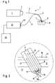
- FIG. 1shows a schematic diagram of the inventive analysis system
- FIG. 2shows an enlarged diagram of a detail from FIG. 1 in cross-section with a scattered-light percutaneous sensor inserted into the skin;
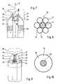
- FIG. 3shows a schematic perspective diagram of a sensor head
- FIG. 4shows a cross-section through the light guides of the sensor head shown in FIG. 3 ;
- FIG. 5shows a schematic perspective diagram of a second embodiment of a sensor head
- FIG. 6shows a cross-section through the light guides of the sensor head depicted in FIG. 5 ;
- FIG. 7shows a schematic longitudinal section through a third embodiment of a sensor head
- FIG. 8shows a cross-section through the light guides of the sensor head depicted in FIG. 7 ;
- FIG. 9shows a schematic perspective view of a fourth embodiment of a sensor head
- FIG. 10shows a cross-section through the light guides of the sensor head depicted in FIG. 9 ;
- FIG. 11shows a schematic perspective diagram of a fifth embodiment of a sensor head
- FIG. 12shows a graphic plot of the absolute Raman intensity and the relative Raman intensity as a function of the angle of inclination of a reflective surface having filter properties provided on the sensor head.
- FIG. 1shows in a highly schematized diagram the essential components of an inventive analysis system designated on the whole by 1.
- the light sourceis a laser 2 (preferably a semiconductor laser) which emits visible light or light from the near infrared.
- the primary light generated by the light source 2is coupled into an inbound light guide 4 through a coupling device 3 .
- the inbound light guide 4is formed for a part of its length by the central fiber of an optical fiber bundle 5 whose distal section is designed as a scattered-light percutaneous sensor 7 piercing through the skin surface and into the skin.
- the distal end of the percutaneous sensor which is inserted into the skin 8is designated sensor head 9 .
- FIG. 2Details of the generation and detection of the Raman-scattered light are shown in FIG. 2 in an enlarged detail diagram which is also highly schematized. Further details may be taken from FIGS. 7 and 8 .
- the sensor head 9penetrates through the skin surface and the underlying layers of skin, namely the epidermis 11 and the dermis 12 , into the subcutis 13 so that the test volume 15 contains interstitial fluid at the distal end of the sensor head in the direction of insertion.
- the primary lightpasses through a light irradiation surface 18 , which is formed by the distal end face of the inbound light guide 4 , into the test volume 15 .
- a bandpass filterpreferably on its most distal end, to ensure that the primary light penetrating into the test volume 15 has an extremely narrow bandwidth.
- the secondary light occurring in the test volume 15contains Raman components as well as Rayleigh components and fluorescence components.
- a large portion of the scattered secondary light 19penetrates through a light receiving surface 20 into a detection light guide 21 (see FIG. 7 ).
- the detection light guide 21consists of a plurality of optical fibers 22 which are arranged at least on both sides of the inbound light guide 4 .
- detection light guidemust not be interpreted in a restrictive sense as pertaining to a single fiber-optic element, in particular an optical fiber.
- detection light guiderefers to the totality of fiber-optic elements that serve in an inventive system to transport the scattered light from a light receiving surface 20 (which may consist of a plurality of partial surfaces) to the spectrometer. Consequently, the detection light guide may consist of a plurality of fiber-optic elements running in parallel as well as a plurality of fiber-optic elements arranged in succession, made of a suitable transparent material in which the detection light is transported. The same is also basically true for the inbound light guide, although this is, in the area of the sensor head, preferably formed by a single central optical fiber.
- the optical fibers 22 of the detection light guide 21reflection takes place at a reflective surface 23 (see FIG. 7 ) which is inclined obliquely to the axis of the primary light 16 . It runs on the side of the detection light guide 21 which faces away from the primary light beam 16 a.
- the detected secondary lightis conducted in the detection light guide 21 to a wavelength-selective detection device 24 having at its input a notch filter (negated bandpass filter) which eliminates as much as possible of the wavelength of the primary light and thus the elastically scattered Rayleigh components of the secondary light.
- a notch filternode-pass filter
- the detected lightis divided spectrally and the resulting spectrum, which contains the information for determining the glucose concentration, is recorded digitally.
- the digitized spectrumis transmitted to an electronic analyzer device 26 , e.g., a computer and is analyzed there. This is preferably done by means of a multivariate analysis method such as used in spectroscopy (e.g., principle component regression, partial least squares). Such methods are described, for example, in H.
- FIGS. 3 through 11illustrate various preferred embodiments of the sensor head 9 .
- the distal end of sensor head 9is always enclosed by a semipermeable membrane 30 such that macromolecules having a molecular weight above the exclusion limit of the membrane cannot penetrate into the test volume 15 which is enclosed by the membrane 30 .
- a significant reduction in the interfering fluorescenceis achieved. This is true in particular in the preferred range of the primary light wavelength, i.e., in the visible and very near infrared portion of the spectrum.
- suppression of the fluorescence backgroundis optimal in the spectral range between 550 and 750 nm, in particular between 570 and 650 nm.
- the detection light guide 21comprises six optical fibers 22 which are arranged in a ring pattern around a central optical fiber forming the inbound light guide 4 .
- the totality of the optical fibers 22thus forms a detection fiber-optical ring 33 which surrounds the central inbound light guide 4 .
- All fibersare surrounded by cladding 32 (as is customary in fiber-optic technology) which has a lower refractive index than the fiber material. Therefore, the light transport in the fibers is achieved by total reflection in known manner and the fibers are optically separated from one another.
- the light receiving surface 20 of the detection light guide 21is formed by the end faces of the optical fibers 22 running normal to the fiber axis (“flat face” arrangement).
- a reflective surface 23is formed by the inside surface of a reflector element 34 which form a lateral limitation of the test volume 15 and is not part of the detection light guide 21 . It is inclined at an angle ⁇ to the axis A of the primary light beam 16 a emerging from the light irradiation surface 18 such that the scattered secondary light 19 is reflected in the direction of the light receiving surface 20 of the detection light guide 21 , i.e., it penetrates to an increased extent into the detection light guide 21 .
- the reflector element 34is in the preferred embodiment depicted in FIGS. 3 and 5 designed as a reflecting sleeve 35 which surrounds the primary light beam 16 a and has slightly conically inclined side walls.
- the reflector element 34preferably consists completely of a thin film of a highly reflective metal such as gold. In principle, however, it may also be made of a material that is not itself reflective (such as a plastic) but has a reflective (metallic) coating—preferably on the inside facing the primary light beam 16 a.
- Holes 36are provided in the wall of the reflecting sleeve 35 to improve the liquid exchange with the volume enclosed thereby—in addition to the distal sleeve opening 37 through which the primary light beam 16 a penetrates.
- suitable filter coatingsare preferably provided, namely a bandpass filter 17 at the light irradiation surface 18 and a notch filter 27 on the light receiving surface 20 (for the sake of simplicity, shown only with one optical fiber 22 in FIG. 3 ).
- FIGS. 5 and 6differs from that of FIGS. 3 and 4 only in that the light guide ring 33 is not formed by a plurality of individual fibers 22 but instead by a fiber-optic tube 38 . Thereby the light receiving surface is increased (at a given outside diameter) and the cross-section available for conducting the detection light is also increased. However, production is substantially more difficult than with the embodiment depicted in FIGS. 3 and 4 .
- the preferred dimensions of the reflecting sleeve 35The angle of inclination ⁇ of the reflective surface 23 to the axis A of the primary light beam 16 a should be very acute, with values of less than 10 degrees being preferred.
- the axial length of the reflecting sleeveis preferably between 1 mm and 20 mm, with values of 3 mm or 5 mm being preferred as the lower limit and 10 mm as the upper limit.
- the low inclination of the reflecting sleeveresults in the test volume 15 extending forward beyond the distal sleeve opening 37 . Therefore, the test volume 15 is large, so the detected Raman intensity is increased.
- the size of the test volume 15is influenced in a positive sense by the fact that a thin-walled reflecting sleeve 35 is used, its proximal diameter (facing the detection light guide) approximately matching that of the connected section of the detection light guide. This maximizes the test volume which is possible at a given diameter of the sensor head 9 .
- FIGS. 7 through 11have in common the fact that (as is also the case in FIG. 2 ) the reflective surface 23 is formed by an outer boundary surface 40 of the detection light guide 21 which surface faces away from the primary light beam 16 a emerging from the light irradiation surface 18 .
- FIG. 7shows the geometry according to FIG. 2 more clearly.
- the light receiving surface 20 of the detection light guide 21is formed by lateral surfaces of the optical fibers 22 which run axially parallel and face the primary light beam 16 a .
- the inbound light guide 4is shorter than the detection light guide 21 so that the test volume 15 is rearwardly enclosed by the light irradiation surface 18 of the inbound light guide 4 and toward the sides it is enclosed by the light receiving surface 20 of the detection light guide 21 .
- the aforementioned bandpass filters and notch filters 17 and 27are provided. Filtering of the detection light is also improved by integrating an additional notch filter 39 into the detection light guide as close as possible to the light receiving surface 20 .
- the most distal end of the detection light guide 21is formed by a transparent ring segment body 41 whose conical outside surface functions as a reflective surface 23 . It has a central recess 42 which is aligned with the inbound light guide 4 . The bordering wall of the recess 42 forms the light receiving surface 20 of the detection light guide 21 and encloses the test volume 15 .
- ring segment bodyin this context is understood to refer to a transparent body having a conical outside boundary surface 40 and a central recess of the type shown here. Its base surface 44 which faces the adjacent part of the detection light guide 22 , is aligned with the detection light guide ring 33 .
- the ring segment bodymust not be a complete truncated cone, however. Instead it is advantageous if, as shown here, it is interrupted to form a plurality of segments between which there are gaps forming liquid exchange openings 43 through which the liquid exchange between the test volume 15 and the space outside the ring segment body 41 is improved.
- the desired reflection properties of the reflective surface 23can be achieved, for example, by coating it with a cladding so that total reflection occurs on the boundary surface of the detection light guide 21 .
- a metallic reflective coating on the boundary surface 40 forming the reflective surface 23is preferred.
- the boundary surface 40is coated with a filter coating 45 which reflects the Raman-scattered light but is permeable for the wavelength of the primary light. This improves the S/N ratio.
- FIGS. 9 / 10 and 11differ (similarly to FIGS. 3 / 4 and 5 / 6 ) through the use of different types of light guide rings 33 , namely a plurality of optical fibers 22 or a tubular fiber-optic element 38 .
- the angle of inclination ⁇ of the reflective surface 23 to the axis of the primary light beam 16 ashould preferably be between 10° and 40° in the embodiment depicted in FIGS. 7 through 11 , where the reflective surface 23 is formed by an outer boundary surface of the detection light guide 21 .
- the results of investigations of this typeare depicted graphically in FIGS. 12 through 14 .
- FIG. 12shows the results of simulation experiments for different measurement geometries, showing the dependence of the absolute Raman power P RA (right ordinate) on the angle ⁇ as a series of crosses (+) that are not connected, and the relationship of the Raman power P RA to the sum of the detected power of the incident light P PR (Rayleigh scattered and reflected primary light; left ordinate) as crosses (+) connected by a dotted line.
- results shown hereare based on the measurement geometry according to FIG. 7 , where the reflective surface is coated with a filter coating so that the Raman-scattered light is reflected on the reflective surface 23 but primary light is allowed to pass through. It can be seen here that very good results are achieved with regard to the absolute intensity of the Raman light as well as the ratio between P RA and P PR at relatively small angles, in particular between approx. 15° and approx. 35°.
Landscapes
- Health & Medical Sciences (AREA)
- Life Sciences & Earth Sciences (AREA)
- Physics & Mathematics (AREA)
- General Health & Medical Sciences (AREA)
- Pathology (AREA)
- Biomedical Technology (AREA)
- Veterinary Medicine (AREA)
- Heart & Thoracic Surgery (AREA)
- Medical Informatics (AREA)
- Molecular Biology (AREA)
- Surgery (AREA)
- Animal Behavior & Ethology (AREA)
- Biophysics (AREA)
- Public Health (AREA)
- Engineering & Computer Science (AREA)
- Optics & Photonics (AREA)
- Emergency Medicine (AREA)
- Spectroscopy & Molecular Physics (AREA)
- Nuclear Medicine, Radiotherapy & Molecular Imaging (AREA)
- Chemical & Material Sciences (AREA)
- Analytical Chemistry (AREA)
- Biochemistry (AREA)
- General Physics & Mathematics (AREA)
- Immunology (AREA)
- Investigating, Analyzing Materials By Fluorescence Or Luminescence (AREA)
Abstract
Description
- a light transmitter for generating monochromatic primary light,
- a scattered-light percutaneous sensor which
- is insertable into the skin, so that a sensor head at the distal end of the scattered-light percutaneous sensor is located inside the skin,
- includes an inbound light guide in which primary light is conducted through the skin surface into the interior of the body and which has a light irradiation surface at its distal end through which the primary light penetrates from the inbound light guide into a test volume of the tissue of the patient, and
- includes a detection light guide having at its distal end a light receiving surface through which secondary light scattered in the test volume penetrates into the detection light guide and in which the secondary light is conducted through the skin surface out of the patient's body, and
- a wavelength-selective detection device that is connected to the detection light guide for detection of Raman-scattered components of the secondary light and an evaluation device for determining the concentration of the analyte from the Raman-scattered components of the secondary light.
Claims (32)
Applications Claiming Priority (2)
| Application Number | Priority Date | Filing Date | Title |
|---|---|---|---|
| DE10311452.1 | 2003-03-15 | ||
| DE10311452ADE10311452B4 (en) | 2003-03-15 | 2003-03-15 | Analysis system for the reagent-free determination of the concentration of an analyte in living tissue |
Publications (2)
| Publication Number | Publication Date |
|---|---|
| US20040260162A1 US20040260162A1 (en) | 2004-12-23 |
| US7277740B2true US7277740B2 (en) | 2007-10-02 |
Family
ID=32945903
Family Applications (1)
| Application Number | Title | Priority Date | Filing Date |
|---|---|---|---|
| US10/800,215Expired - Fee RelatedUS7277740B2 (en) | 2003-03-15 | 2004-03-12 | Analysis system for reagent-free determination of the concentration of an analyte in living tissue |
Country Status (2)
| Country | Link |
|---|---|
| US (1) | US7277740B2 (en) |
| DE (1) | DE10311452B4 (en) |
Cited By (63)
| Publication number | Priority date | Publication date | Assignee | Title |
|---|---|---|---|---|
| US20080188725A1 (en)* | 2007-02-06 | 2008-08-07 | Markle David R | Optical systems and methods for ratiometric measurement of blood glucose concentration |
| WO2009121360A1 (en)* | 2008-03-31 | 2009-10-08 | Bmc Ventures A/S | A system for determining a concentration of a substance in a body fluid |
| US20090264719A1 (en)* | 2008-04-17 | 2009-10-22 | Glumetrics, Inc. | Sensor for percutaneous intravascular deployment without an indwelling cannula |
| US7740588B1 (en)* | 2005-06-24 | 2010-06-22 | Michael Sciarra | Wireless respiratory and heart rate monitoring system |
| US7875047B2 (en) | 2002-04-19 | 2011-01-25 | Pelikan Technologies, Inc. | Method and apparatus for a multi-use body fluid sampling device with sterility barrier release |
| US7892183B2 (en) | 2002-04-19 | 2011-02-22 | Pelikan Technologies, Inc. | Method and apparatus for body fluid sampling and analyte sensing |
| US7901365B2 (en) | 2002-04-19 | 2011-03-08 | Pelikan Technologies, Inc. | Method and apparatus for penetrating tissue |
| US7909778B2 (en) | 2002-04-19 | 2011-03-22 | Pelikan Technologies, Inc. | Method and apparatus for penetrating tissue |
| US7909774B2 (en) | 2002-04-19 | 2011-03-22 | Pelikan Technologies, Inc. | Method and apparatus for penetrating tissue |
| US7909777B2 (en) | 2002-04-19 | 2011-03-22 | Pelikan Technologies, Inc | Method and apparatus for penetrating tissue |
| US7909775B2 (en) | 2001-06-12 | 2011-03-22 | Pelikan Technologies, Inc. | Method and apparatus for lancet launching device integrated onto a blood-sampling cartridge |
| US7914465B2 (en) | 2002-04-19 | 2011-03-29 | Pelikan Technologies, Inc. | Method and apparatus for penetrating tissue |
| US7976476B2 (en) | 2002-04-19 | 2011-07-12 | Pelikan Technologies, Inc. | Device and method for variable speed lancet |
| US7981056B2 (en) | 2002-04-19 | 2011-07-19 | Pelikan Technologies, Inc. | Methods and apparatus for lancet actuation |
| US7981055B2 (en) | 2001-06-12 | 2011-07-19 | Pelikan Technologies, Inc. | Tissue penetration device |
| US7988645B2 (en) | 2001-06-12 | 2011-08-02 | Pelikan Technologies, Inc. | Self optimizing lancing device with adaptation means to temporal variations in cutaneous properties |
| US8007446B2 (en) | 2002-04-19 | 2011-08-30 | Pelikan Technologies, Inc. | Method and apparatus for penetrating tissue |
| US8062231B2 (en) | 2002-04-19 | 2011-11-22 | Pelikan Technologies, Inc. | Method and apparatus for penetrating tissue |
| US8079960B2 (en) | 2002-04-19 | 2011-12-20 | Pelikan Technologies, Inc. | Methods and apparatus for lancet actuation |
| US8197421B2 (en) | 2002-04-19 | 2012-06-12 | Pelikan Technologies, Inc. | Method and apparatus for penetrating tissue |
| WO2012018717A3 (en)* | 2010-08-06 | 2012-06-21 | Hach Company | Annular optical device |
| US8221334B2 (en) | 2002-04-19 | 2012-07-17 | Sanofi-Aventis Deutschland Gmbh | Method and apparatus for penetrating tissue |
| US8251921B2 (en) | 2003-06-06 | 2012-08-28 | Sanofi-Aventis Deutschland Gmbh | Method and apparatus for body fluid sampling and analyte sensing |
| US8262614B2 (en) | 2003-05-30 | 2012-09-11 | Pelikan Technologies, Inc. | Method and apparatus for fluid injection |
| US8267870B2 (en) | 2002-04-19 | 2012-09-18 | Sanofi-Aventis Deutschland Gmbh | Method and apparatus for body fluid sampling with hybrid actuation |
| US8282576B2 (en) | 2003-09-29 | 2012-10-09 | Sanofi-Aventis Deutschland Gmbh | Method and apparatus for an improved sample capture device |
| US8296918B2 (en) | 2003-12-31 | 2012-10-30 | Sanofi-Aventis Deutschland Gmbh | Method of manufacturing a fluid sampling device with improved analyte detecting member configuration |
| US8333710B2 (en) | 2002-04-19 | 2012-12-18 | Sanofi-Aventis Deutschland Gmbh | Tissue penetration device |
| US8360992B2 (en) | 2002-04-19 | 2013-01-29 | Sanofi-Aventis Deutschland Gmbh | Method and apparatus for penetrating tissue |
| US8372016B2 (en) | 2002-04-19 | 2013-02-12 | Sanofi-Aventis Deutschland Gmbh | Method and apparatus for body fluid sampling and analyte sensing |
| US8382682B2 (en) | 2002-04-19 | 2013-02-26 | Sanofi-Aventis Deutschland Gmbh | Method and apparatus for penetrating tissue |
| US8435190B2 (en) | 2002-04-19 | 2013-05-07 | Sanofi-Aventis Deutschland Gmbh | Method and apparatus for penetrating tissue |
| US8439872B2 (en) | 1998-03-30 | 2013-05-14 | Sanofi-Aventis Deutschland Gmbh | Apparatus and method for penetration with shaft having a sensor for sensing penetration depth |
| US8467843B2 (en) | 2009-11-04 | 2013-06-18 | Glumetrics, Inc. | Optical sensor configuration for ratiometric correction of blood glucose measurement |
| US8535262B2 (en) | 2007-11-21 | 2013-09-17 | Glumetrics, Inc. | Use of an equilibrium intravascular sensor to achieve tight glycemic control |
| US8556829B2 (en) | 2002-04-19 | 2013-10-15 | Sanofi-Aventis Deutschland Gmbh | Method and apparatus for penetrating tissue |
| US8571659B2 (en) | 2006-05-17 | 2013-10-29 | Cardiac Pacemakers, Inc. | Implantable medical device with chemical sensor and related methods |
| US8574895B2 (en) | 2002-12-30 | 2013-11-05 | Sanofi-Aventis Deutschland Gmbh | Method and apparatus using optical techniques to measure analyte levels |
| US8641644B2 (en) | 2000-11-21 | 2014-02-04 | Sanofi-Aventis Deutschland Gmbh | Blood testing apparatus having a rotatable cartridge with multiple lancing elements and testing means |
| US8652831B2 (en) | 2004-12-30 | 2014-02-18 | Sanofi-Aventis Deutschland Gmbh | Method and apparatus for analyte measurement test time |
| US8668656B2 (en) | 2003-12-31 | 2014-03-11 | Sanofi-Aventis Deutschland Gmbh | Method and apparatus for improving fluidic flow and sample capture |
| US8687286B2 (en) | 2009-09-11 | 2014-04-01 | Hach Company | Meso-optic device |
| US8702624B2 (en) | 2006-09-29 | 2014-04-22 | Sanofi-Aventis Deutschland Gmbh | Analyte measurement device with a single shot actuator |
| US8715589B2 (en) | 2009-09-30 | 2014-05-06 | Medtronic Minimed, Inc. | Sensors with thromboresistant coating |
| US8721671B2 (en) | 2001-06-12 | 2014-05-13 | Sanofi-Aventis Deutschland Gmbh | Electric lancet actuator |
| US8738107B2 (en) | 2007-05-10 | 2014-05-27 | Medtronic Minimed, Inc. | Equilibrium non-consuming fluorescence sensor for real time intravascular glucose measurement |
| US8784335B2 (en) | 2002-04-19 | 2014-07-22 | Sanofi-Aventis Deutschland Gmbh | Body fluid sampling device with a capacitive sensor |
| US8828203B2 (en) | 2004-05-20 | 2014-09-09 | Sanofi-Aventis Deutschland Gmbh | Printable hydrogels for biosensors |
| US8965476B2 (en) | 2010-04-16 | 2015-02-24 | Sanofi-Aventis Deutschland Gmbh | Tissue penetration device |
| US9144401B2 (en) | 2003-06-11 | 2015-09-29 | Sanofi-Aventis Deutschland Gmbh | Low pain penetrating member |
| US9226699B2 (en) | 2002-04-19 | 2016-01-05 | Sanofi-Aventis Deutschland Gmbh | Body fluid sampling module with a continuous compression tissue interface surface |
| US9248267B2 (en) | 2002-04-19 | 2016-02-02 | Sanofi-Aventis Deustchland Gmbh | Tissue penetration device |
| US9314194B2 (en) | 2002-04-19 | 2016-04-19 | Sanofi-Aventis Deutschland Gmbh | Tissue penetration device |
| US9351680B2 (en) | 2003-10-14 | 2016-05-31 | Sanofi-Aventis Deutschland Gmbh | Method and apparatus for a variable user interface |
| US9375169B2 (en) | 2009-01-30 | 2016-06-28 | Sanofi-Aventis Deutschland Gmbh | Cam drive for managing disposable penetrating member actions with a single motor and motor and control system |
| US9386944B2 (en) | 2008-04-11 | 2016-07-12 | Sanofi-Aventis Deutschland Gmbh | Method and apparatus for analyte detecting device |
| US9427532B2 (en) | 2001-06-12 | 2016-08-30 | Sanofi-Aventis Deutschland Gmbh | Tissue penetration device |
| US20170007163A1 (en)* | 2014-03-28 | 2017-01-12 | Terumo Kabushiki Kaisha | Fluorescence sensor |
| US20170248510A1 (en)* | 2016-02-29 | 2017-08-31 | Cordouan Technologies | Devices and methods for characterizing particles dispersed in a liquid medium |
| US9775553B2 (en) | 2004-06-03 | 2017-10-03 | Sanofi-Aventis Deutschland Gmbh | Method and apparatus for a fluid sampling device |
| US9795747B2 (en) | 2010-06-02 | 2017-10-24 | Sanofi-Aventis Deutschland Gmbh | Methods and apparatus for lancet actuation |
| US9820684B2 (en) | 2004-06-03 | 2017-11-21 | Sanofi-Aventis Deutschland Gmbh | Method and apparatus for a fluid sampling device |
| US10716500B2 (en) | 2015-06-29 | 2020-07-21 | Cardiac Pacemakers, Inc. | Systems and methods for normalization of chemical sensor data based on fluid state changes |
Families Citing this family (13)
| Publication number | Priority date | Publication date | Assignee | Title |
|---|---|---|---|---|
| US20040001662A1 (en)* | 2002-06-27 | 2004-01-01 | Biotechplex Corporation | Method of and apparatus for measuring oscillatory motion |
| DE102005024511B4 (en)* | 2005-05-26 | 2007-07-26 | Hermsdorfer Institut Für Technische Keramik E.V. | Measuring device for Raman spectrometric, non-invasive glucose determination |
| US7713196B2 (en) | 2007-03-09 | 2010-05-11 | Nellcor Puritan Bennett Llc | Method for evaluating skin hydration and fluid compartmentalization |
| US8560059B2 (en)* | 2007-03-09 | 2013-10-15 | Covidien Lp | System and methods for optical sensing and drug delivery using microneedles |
| US8615281B2 (en)* | 2007-11-21 | 2013-12-24 | Medingo Ltd. | Hypodermic optical monitoring of bodily analyte |
| DE102014210440B4 (en) | 2014-06-03 | 2018-07-19 | Fraunhofer-Gesellschaft zur Förderung der angewandten Forschung e.V. | glucose sensor |
| WO2017040927A1 (en)* | 2015-09-02 | 2017-03-09 | University Of Virginia Patent Foundation | System, method, and computer readable medium for dynamic insulin sensitivity in diabetic pump users |
| CN108968976B (en) | 2017-05-31 | 2022-09-13 | 心脏起搏器股份公司 | Implantable medical device with chemical sensor |
| WO2019023093A1 (en) | 2017-07-26 | 2019-01-31 | Cardiac Pacemakers, Inc. | Systems and methods for disambiguation of posture |
| CN109381195B (en) | 2017-08-10 | 2023-01-10 | 心脏起搏器股份公司 | Systems and methods including electrolyte sensor fusion |
| CN109419515B (en) | 2017-08-23 | 2023-03-24 | 心脏起搏器股份公司 | Implantable chemical sensor with staged activation |
| CN109864746B (en) | 2017-12-01 | 2023-09-29 | 心脏起搏器股份公司 | Multimode analyte sensor for medical devices |
| CN109864747B (en) | 2017-12-05 | 2023-08-25 | 心脏起搏器股份公司 | Multimode analyte sensor optoelectronic interface |
Citations (24)
| Publication number | Priority date | Publication date | Assignee | Title |
|---|---|---|---|---|
| US3966300A (en)* | 1972-01-24 | 1976-06-29 | Jenaer Glaswerk Schott & Gen. | Light conducting fibers of quartz glass |
| US4201222A (en) | 1977-08-31 | 1980-05-06 | Thomas Haase | Method and apparatus for in vivo measurement of blood gas partial pressures, blood pressure and blood pulse |
| US4925268A (en)* | 1988-07-25 | 1990-05-15 | Abbott Laboratories | Fiber-optic physiological probes |
| US5000901A (en) | 1988-07-25 | 1991-03-19 | Abbott Laboratories | Fiber-optic physiological probes |
| US5005576A (en) | 1988-04-09 | 1991-04-09 | Hewlett-Packard Company | Optical probe |
| US5127077A (en) | 1988-07-25 | 1992-06-30 | Abbott Laboratories | Fiber-optic physiological probes |
| US5143066A (en) | 1990-05-08 | 1992-09-01 | University Of Pittsburgh | Optical fiber sensors for continuous monitoring of biochemicals and related method |
| US5173432A (en) | 1987-12-14 | 1992-12-22 | The Dow Chemical Company | Apparatus and method for measuring the concentration or partial pressure of oxygen |
| US5348003A (en)* | 1992-09-03 | 1994-09-20 | Sirraya, Inc. | Method and apparatus for chemical analysis |
| US5423320A (en) | 1993-04-20 | 1995-06-13 | Argus Critical Care, Inc. | Air tonometry method and apparatus for measuring intraluminal gastrointestinal pCO2 and pO2 |
| US5434084A (en) | 1989-09-06 | 1995-07-18 | The Washington Research Foundation | Flow optrode having separate reaction and detection chambers |
| US5481113A (en) | 1993-08-05 | 1996-01-02 | Kyoto Daiichi Kagaku Co., Ltd. | Apparatus and method for measuring concentrations of components with light scattering |
| US5553616A (en)* | 1993-11-30 | 1996-09-10 | Florida Institute Of Technology | Determination of concentrations of biological substances using raman spectroscopy and artificial neural network discriminator |
| WO1997019344A1 (en) | 1995-11-22 | 1997-05-29 | Legacy Good Samaritan Hospital And Medical Center | Device for monitoring changes in analyte concentration |
| WO1997034175A1 (en) | 1996-03-13 | 1997-09-18 | Visionex, Inc. | Method and apparatus for improved fiber optic light management |
| WO1997042868A1 (en) | 1996-05-09 | 1997-11-20 | Boehringer Mannheim Gmbh | Determination of glucose concentration in tissue |
| US5835649A (en) | 1997-06-02 | 1998-11-10 | The University Of British Columbia | Light directing and collecting fiber optic probe |
| WO1999007277A1 (en)* | 1997-08-09 | 1999-02-18 | Roche Diagnostics Gmbh | Analytical device for in vivo analysis in the body of a patient |
| US6151522A (en) | 1998-03-16 | 2000-11-21 | The Research Foundation Of Cuny | Method and system for examining biological materials using low power CW excitation raman spectroscopy |
| US6167290A (en)* | 1999-02-03 | 2000-12-26 | Bayspec, Inc. | Method and apparatus of non-invasive measurement of human/animal blood glucose and other metabolites |
| WO2002007585A2 (en)* | 2000-07-13 | 2002-01-31 | Virginia Commonwealth University | Tissue interrogation spectroscopy |
| US6370406B1 (en)* | 1995-11-20 | 2002-04-09 | Cirrex Corp. | Method and apparatus for analyzing a test material by inducing and detecting light-matter interactions |
| US6377828B1 (en)* | 1997-11-12 | 2002-04-23 | Lightouch Medical, Inc. | Method for non-invasive measurement of an analyte |
| DE10027100C2 (en) | 2000-05-31 | 2002-08-08 | Klaus Mueller-Dethlefs | Method and device for detecting substances in body fluids |
- 2003
- 2003-03-15DEDE10311452Apatent/DE10311452B4/ennot_activeExpired - Fee Related
- 2004
- 2004-03-12USUS10/800,215patent/US7277740B2/ennot_activeExpired - Fee Related
Patent Citations (25)
| Publication number | Priority date | Publication date | Assignee | Title |
|---|---|---|---|---|
| US3966300A (en)* | 1972-01-24 | 1976-06-29 | Jenaer Glaswerk Schott & Gen. | Light conducting fibers of quartz glass |
| US4201222A (en) | 1977-08-31 | 1980-05-06 | Thomas Haase | Method and apparatus for in vivo measurement of blood gas partial pressures, blood pressure and blood pulse |
| US5173432A (en) | 1987-12-14 | 1992-12-22 | The Dow Chemical Company | Apparatus and method for measuring the concentration or partial pressure of oxygen |
| US5005576A (en) | 1988-04-09 | 1991-04-09 | Hewlett-Packard Company | Optical probe |
| US4925268A (en)* | 1988-07-25 | 1990-05-15 | Abbott Laboratories | Fiber-optic physiological probes |
| US5000901A (en) | 1988-07-25 | 1991-03-19 | Abbott Laboratories | Fiber-optic physiological probes |
| US5127077A (en) | 1988-07-25 | 1992-06-30 | Abbott Laboratories | Fiber-optic physiological probes |
| US5434084A (en) | 1989-09-06 | 1995-07-18 | The Washington Research Foundation | Flow optrode having separate reaction and detection chambers |
| US5143066A (en) | 1990-05-08 | 1992-09-01 | University Of Pittsburgh | Optical fiber sensors for continuous monitoring of biochemicals and related method |
| US5348003A (en)* | 1992-09-03 | 1994-09-20 | Sirraya, Inc. | Method and apparatus for chemical analysis |
| US5423320A (en) | 1993-04-20 | 1995-06-13 | Argus Critical Care, Inc. | Air tonometry method and apparatus for measuring intraluminal gastrointestinal pCO2 and pO2 |
| US5481113A (en) | 1993-08-05 | 1996-01-02 | Kyoto Daiichi Kagaku Co., Ltd. | Apparatus and method for measuring concentrations of components with light scattering |
| US5553616A (en)* | 1993-11-30 | 1996-09-10 | Florida Institute Of Technology | Determination of concentrations of biological substances using raman spectroscopy and artificial neural network discriminator |
| US6370406B1 (en)* | 1995-11-20 | 2002-04-09 | Cirrex Corp. | Method and apparatus for analyzing a test material by inducing and detecting light-matter interactions |
| WO1997019344A1 (en) | 1995-11-22 | 1997-05-29 | Legacy Good Samaritan Hospital And Medical Center | Device for monitoring changes in analyte concentration |
| WO1997034175A1 (en) | 1996-03-13 | 1997-09-18 | Visionex, Inc. | Method and apparatus for improved fiber optic light management |
| WO1997042868A1 (en) | 1996-05-09 | 1997-11-20 | Boehringer Mannheim Gmbh | Determination of glucose concentration in tissue |
| US5835649A (en) | 1997-06-02 | 1998-11-10 | The University Of British Columbia | Light directing and collecting fiber optic probe |
| WO1999007277A1 (en)* | 1997-08-09 | 1999-02-18 | Roche Diagnostics Gmbh | Analytical device for in vivo analysis in the body of a patient |
| US6584335B1 (en)* | 1997-08-09 | 2003-06-24 | Roche Diagnostics Gmbh | Analytical device for in vivo analysis in the body of a patient |
| US6377828B1 (en)* | 1997-11-12 | 2002-04-23 | Lightouch Medical, Inc. | Method for non-invasive measurement of an analyte |
| US6151522A (en) | 1998-03-16 | 2000-11-21 | The Research Foundation Of Cuny | Method and system for examining biological materials using low power CW excitation raman spectroscopy |
| US6167290A (en)* | 1999-02-03 | 2000-12-26 | Bayspec, Inc. | Method and apparatus of non-invasive measurement of human/animal blood glucose and other metabolites |
| DE10027100C2 (en) | 2000-05-31 | 2002-08-08 | Klaus Mueller-Dethlefs | Method and device for detecting substances in body fluids |
| WO2002007585A2 (en)* | 2000-07-13 | 2002-01-31 | Virginia Commonwealth University | Tissue interrogation spectroscopy |
Non-Patent Citations (2)
| Title |
|---|
| Petrich, W., "Mid-Infrared and Raman Spectroscopy for Medical Diagnostics". Applied Spectroscopy Reviews, 36(2&3), 181-237 (2001). |
| Shim, MG, "Assessment of Ex vivo and In vivo Near-Infrared Raman Spectroscopy for the Classification of Dysplasia Within Barrett's Esophagus." Biomedical Spectroscopy: Vibrational Spectroscopy and Other Novel Techniques, Proceedings of SPIE vol. 3918 (2000), 114-119. |
Cited By (138)
| Publication number | Priority date | Publication date | Assignee | Title |
|---|---|---|---|---|
| US8439872B2 (en) | 1998-03-30 | 2013-05-14 | Sanofi-Aventis Deutschland Gmbh | Apparatus and method for penetration with shaft having a sensor for sensing penetration depth |
| US8641644B2 (en) | 2000-11-21 | 2014-02-04 | Sanofi-Aventis Deutschland Gmbh | Blood testing apparatus having a rotatable cartridge with multiple lancing elements and testing means |
| US8622930B2 (en) | 2001-06-12 | 2014-01-07 | Sanofi-Aventis Deutschland Gmbh | Tissue penetration device |
| US8211037B2 (en) | 2001-06-12 | 2012-07-03 | Pelikan Technologies, Inc. | Tissue penetration device |
| US8206317B2 (en) | 2001-06-12 | 2012-06-26 | Sanofi-Aventis Deutschland Gmbh | Tissue penetration device |
| US9427532B2 (en) | 2001-06-12 | 2016-08-30 | Sanofi-Aventis Deutschland Gmbh | Tissue penetration device |
| US8845550B2 (en) | 2001-06-12 | 2014-09-30 | Sanofi-Aventis Deutschland Gmbh | Tissue penetration device |
| US8721671B2 (en) | 2001-06-12 | 2014-05-13 | Sanofi-Aventis Deutschland Gmbh | Electric lancet actuator |
| US8679033B2 (en) | 2001-06-12 | 2014-03-25 | Sanofi-Aventis Deutschland Gmbh | Tissue penetration device |
| US9802007B2 (en) | 2001-06-12 | 2017-10-31 | Sanofi-Aventis Deutschland Gmbh | Methods and apparatus for lancet actuation |
| US7909775B2 (en) | 2001-06-12 | 2011-03-22 | Pelikan Technologies, Inc. | Method and apparatus for lancet launching device integrated onto a blood-sampling cartridge |
| US8641643B2 (en) | 2001-06-12 | 2014-02-04 | Sanofi-Aventis Deutschland Gmbh | Sampling module device and method |
| US8162853B2 (en) | 2001-06-12 | 2012-04-24 | Pelikan Technologies, Inc. | Tissue penetration device |
| US9937298B2 (en) | 2001-06-12 | 2018-04-10 | Sanofi-Aventis Deutschland Gmbh | Tissue penetration device |
| US9694144B2 (en) | 2001-06-12 | 2017-07-04 | Sanofi-Aventis Deutschland Gmbh | Sampling module device and method |
| US8343075B2 (en) | 2001-06-12 | 2013-01-01 | Sanofi-Aventis Deutschland Gmbh | Tissue penetration device |
| US8382683B2 (en) | 2001-06-12 | 2013-02-26 | Sanofi-Aventis Deutschland Gmbh | Tissue penetration device |
| US8337421B2 (en) | 2001-06-12 | 2012-12-25 | Sanofi-Aventis Deutschland Gmbh | Tissue penetration device |
| US7981055B2 (en) | 2001-06-12 | 2011-07-19 | Pelikan Technologies, Inc. | Tissue penetration device |
| US8282577B2 (en) | 2001-06-12 | 2012-10-09 | Sanofi-Aventis Deutschland Gmbh | Method and apparatus for lancet launching device integrated onto a blood-sampling cartridge |
| US7988645B2 (en) | 2001-06-12 | 2011-08-02 | Pelikan Technologies, Inc. | Self optimizing lancing device with adaptation means to temporal variations in cutaneous properties |
| US8216154B2 (en) | 2001-06-12 | 2012-07-10 | Sanofi-Aventis Deutschland Gmbh | Tissue penetration device |
| US8016774B2 (en) | 2001-06-12 | 2011-09-13 | Pelikan Technologies, Inc. | Tissue penetration device |
| US8360991B2 (en) | 2001-06-12 | 2013-01-29 | Sanofi-Aventis Deutschland Gmbh | Tissue penetration device |
| US8206319B2 (en) | 2001-06-12 | 2012-06-26 | Sanofi-Aventis Deutschland Gmbh | Tissue penetration device |
| US8123700B2 (en) | 2001-06-12 | 2012-02-28 | Pelikan Technologies, Inc. | Method and apparatus for lancet launching device integrated onto a blood-sampling cartridge |
| US9560993B2 (en) | 2001-11-21 | 2017-02-07 | Sanofi-Aventis Deutschland Gmbh | Blood testing apparatus having a rotatable cartridge with multiple lancing elements and testing means |
| US8562545B2 (en) | 2002-04-19 | 2013-10-22 | Sanofi-Aventis Deutschland Gmbh | Tissue penetration device |
| US9226699B2 (en) | 2002-04-19 | 2016-01-05 | Sanofi-Aventis Deutschland Gmbh | Body fluid sampling module with a continuous compression tissue interface surface |
| US8197423B2 (en) | 2002-04-19 | 2012-06-12 | Pelikan Technologies, Inc. | Method and apparatus for penetrating tissue |
| US8202231B2 (en) | 2002-04-19 | 2012-06-19 | Sanofi-Aventis Deutschland Gmbh | Method and apparatus for penetrating tissue |
| US9907502B2 (en) | 2002-04-19 | 2018-03-06 | Sanofi-Aventis Deutschland Gmbh | Method and apparatus for penetrating tissue |
| US8157748B2 (en) | 2002-04-19 | 2012-04-17 | Pelikan Technologies, Inc. | Methods and apparatus for lancet actuation |
| US8079960B2 (en) | 2002-04-19 | 2011-12-20 | Pelikan Technologies, Inc. | Methods and apparatus for lancet actuation |
| US8062231B2 (en) | 2002-04-19 | 2011-11-22 | Pelikan Technologies, Inc. | Method and apparatus for penetrating tissue |
| US8007446B2 (en) | 2002-04-19 | 2011-08-30 | Pelikan Technologies, Inc. | Method and apparatus for penetrating tissue |
| US8221334B2 (en) | 2002-04-19 | 2012-07-17 | Sanofi-Aventis Deutschland Gmbh | Method and apparatus for penetrating tissue |
| US8235915B2 (en) | 2002-04-19 | 2012-08-07 | Sanofi-Aventis Deutschland Gmbh | Method and apparatus for penetrating tissue |
| US9839386B2 (en) | 2002-04-19 | 2017-12-12 | Sanofi-Aventis Deustschland Gmbh | Body fluid sampling device with capacitive sensor |
| US9795334B2 (en) | 2002-04-19 | 2017-10-24 | Sanofi-Aventis Deutschland Gmbh | Method and apparatus for penetrating tissue |
| US8267870B2 (en) | 2002-04-19 | 2012-09-18 | Sanofi-Aventis Deutschland Gmbh | Method and apparatus for body fluid sampling with hybrid actuation |
| US7988644B2 (en) | 2002-04-19 | 2011-08-02 | Pelikan Technologies, Inc. | Method and apparatus for a multi-use body fluid sampling device with sterility barrier release |
| US9724021B2 (en) | 2002-04-19 | 2017-08-08 | Sanofi-Aventis Deutschland Gmbh | Method and apparatus for penetrating tissue |
| US7875047B2 (en) | 2002-04-19 | 2011-01-25 | Pelikan Technologies, Inc. | Method and apparatus for a multi-use body fluid sampling device with sterility barrier release |
| US8333710B2 (en) | 2002-04-19 | 2012-12-18 | Sanofi-Aventis Deutschland Gmbh | Tissue penetration device |
| US8337420B2 (en) | 2002-04-19 | 2012-12-25 | Sanofi-Aventis Deutschland Gmbh | Tissue penetration device |
| US7981056B2 (en) | 2002-04-19 | 2011-07-19 | Pelikan Technologies, Inc. | Methods and apparatus for lancet actuation |
| US8337419B2 (en) | 2002-04-19 | 2012-12-25 | Sanofi-Aventis Deutschland Gmbh | Tissue penetration device |
| US7976476B2 (en) | 2002-04-19 | 2011-07-12 | Pelikan Technologies, Inc. | Device and method for variable speed lancet |
| US7959582B2 (en) | 2002-04-19 | 2011-06-14 | Pelikan Technologies, Inc. | Method and apparatus for penetrating tissue |
| US8360992B2 (en) | 2002-04-19 | 2013-01-29 | Sanofi-Aventis Deutschland Gmbh | Method and apparatus for penetrating tissue |
| US8366637B2 (en) | 2002-04-19 | 2013-02-05 | Sanofi-Aventis Deutschland Gmbh | Method and apparatus for penetrating tissue |
| US8372016B2 (en) | 2002-04-19 | 2013-02-12 | Sanofi-Aventis Deutschland Gmbh | Method and apparatus for body fluid sampling and analyte sensing |
| US8382682B2 (en) | 2002-04-19 | 2013-02-26 | Sanofi-Aventis Deutschland Gmbh | Method and apparatus for penetrating tissue |
| US9498160B2 (en) | 2002-04-19 | 2016-11-22 | Sanofi-Aventis Deutschland Gmbh | Method for penetrating tissue |
| US8388551B2 (en) | 2002-04-19 | 2013-03-05 | Sanofi-Aventis Deutschland Gmbh | Method and apparatus for multi-use body fluid sampling device with sterility barrier release |
| US8403864B2 (en) | 2002-04-19 | 2013-03-26 | Sanofi-Aventis Deutschland Gmbh | Method and apparatus for penetrating tissue |
| US8414503B2 (en) | 2002-04-19 | 2013-04-09 | Sanofi-Aventis Deutschland Gmbh | Methods and apparatus for lancet actuation |
| US8430828B2 (en) | 2002-04-19 | 2013-04-30 | Sanofi-Aventis Deutschland Gmbh | Method and apparatus for a multi-use body fluid sampling device with sterility barrier release |
| US8435190B2 (en) | 2002-04-19 | 2013-05-07 | Sanofi-Aventis Deutschland Gmbh | Method and apparatus for penetrating tissue |
| US7892183B2 (en) | 2002-04-19 | 2011-02-22 | Pelikan Technologies, Inc. | Method and apparatus for body fluid sampling and analyte sensing |
| US9339612B2 (en) | 2002-04-19 | 2016-05-17 | Sanofi-Aventis Deutschland Gmbh | Tissue penetration device |
| US9314194B2 (en) | 2002-04-19 | 2016-04-19 | Sanofi-Aventis Deutschland Gmbh | Tissue penetration device |
| US9248267B2 (en) | 2002-04-19 | 2016-02-02 | Sanofi-Aventis Deustchland Gmbh | Tissue penetration device |
| US8491500B2 (en) | 2002-04-19 | 2013-07-23 | Sanofi-Aventis Deutschland Gmbh | Methods and apparatus for lancet actuation |
| US8496601B2 (en) | 2002-04-19 | 2013-07-30 | Sanofi-Aventis Deutschland Gmbh | Methods and apparatus for lancet actuation |
| US8197421B2 (en) | 2002-04-19 | 2012-06-12 | Pelikan Technologies, Inc. | Method and apparatus for penetrating tissue |
| US9186468B2 (en) | 2002-04-19 | 2015-11-17 | Sanofi-Aventis Deutschland Gmbh | Method and apparatus for penetrating tissue |
| US8556829B2 (en) | 2002-04-19 | 2013-10-15 | Sanofi-Aventis Deutschland Gmbh | Method and apparatus for penetrating tissue |
| US9089294B2 (en) | 2002-04-19 | 2015-07-28 | Sanofi-Aventis Deutschland Gmbh | Analyte measurement device with a single shot actuator |
| US9089678B2 (en) | 2002-04-19 | 2015-07-28 | Sanofi-Aventis Deutschland Gmbh | Method and apparatus for penetrating tissue |
| US9072842B2 (en) | 2002-04-19 | 2015-07-07 | Sanofi-Aventis Deutschland Gmbh | Method and apparatus for penetrating tissue |
| US8574168B2 (en) | 2002-04-19 | 2013-11-05 | Sanofi-Aventis Deutschland Gmbh | Method and apparatus for a multi-use body fluid sampling device with analyte sensing |
| US8579831B2 (en) | 2002-04-19 | 2013-11-12 | Sanofi-Aventis Deutschland Gmbh | Method and apparatus for penetrating tissue |
| US7938787B2 (en) | 2002-04-19 | 2011-05-10 | Pelikan Technologies, Inc. | Method and apparatus for penetrating tissue |
| US8636673B2 (en) | 2002-04-19 | 2014-01-28 | Sanofi-Aventis Deutschland Gmbh | Tissue penetration device |
| US7914465B2 (en) | 2002-04-19 | 2011-03-29 | Pelikan Technologies, Inc. | Method and apparatus for penetrating tissue |
| US7909777B2 (en) | 2002-04-19 | 2011-03-22 | Pelikan Technologies, Inc | Method and apparatus for penetrating tissue |
| US8905945B2 (en) | 2002-04-19 | 2014-12-09 | Dominique M. Freeman | Method and apparatus for penetrating tissue |
| US7901365B2 (en) | 2002-04-19 | 2011-03-08 | Pelikan Technologies, Inc. | Method and apparatus for penetrating tissue |
| US8845549B2 (en) | 2002-04-19 | 2014-09-30 | Sanofi-Aventis Deutschland Gmbh | Method for penetrating tissue |
| US8808201B2 (en) | 2002-04-19 | 2014-08-19 | Sanofi-Aventis Deutschland Gmbh | Methods and apparatus for penetrating tissue |
| US7909774B2 (en) | 2002-04-19 | 2011-03-22 | Pelikan Technologies, Inc. | Method and apparatus for penetrating tissue |
| US8784335B2 (en) | 2002-04-19 | 2014-07-22 | Sanofi-Aventis Deutschland Gmbh | Body fluid sampling device with a capacitive sensor |
| US8690796B2 (en) | 2002-04-19 | 2014-04-08 | Sanofi-Aventis Deutschland Gmbh | Method and apparatus for penetrating tissue |
| US7909778B2 (en) | 2002-04-19 | 2011-03-22 | Pelikan Technologies, Inc. | Method and apparatus for penetrating tissue |
| US8574895B2 (en) | 2002-12-30 | 2013-11-05 | Sanofi-Aventis Deutschland Gmbh | Method and apparatus using optical techniques to measure analyte levels |
| US9034639B2 (en) | 2002-12-30 | 2015-05-19 | Sanofi-Aventis Deutschland Gmbh | Method and apparatus using optical techniques to measure analyte levels |
| US8262614B2 (en) | 2003-05-30 | 2012-09-11 | Pelikan Technologies, Inc. | Method and apparatus for fluid injection |
| US8251921B2 (en) | 2003-06-06 | 2012-08-28 | Sanofi-Aventis Deutschland Gmbh | Method and apparatus for body fluid sampling and analyte sensing |
| US9144401B2 (en) | 2003-06-11 | 2015-09-29 | Sanofi-Aventis Deutschland Gmbh | Low pain penetrating member |
| US10034628B2 (en) | 2003-06-11 | 2018-07-31 | Sanofi-Aventis Deutschland Gmbh | Low pain penetrating member |
| US8945910B2 (en) | 2003-09-29 | 2015-02-03 | Sanofi-Aventis Deutschland Gmbh | Method and apparatus for an improved sample capture device |
| US8282576B2 (en) | 2003-09-29 | 2012-10-09 | Sanofi-Aventis Deutschland Gmbh | Method and apparatus for an improved sample capture device |
| US9351680B2 (en) | 2003-10-14 | 2016-05-31 | Sanofi-Aventis Deutschland Gmbh | Method and apparatus for a variable user interface |
| US9561000B2 (en) | 2003-12-31 | 2017-02-07 | Sanofi-Aventis Deutschland Gmbh | Method and apparatus for improving fluidic flow and sample capture |
| US8296918B2 (en) | 2003-12-31 | 2012-10-30 | Sanofi-Aventis Deutschland Gmbh | Method of manufacturing a fluid sampling device with improved analyte detecting member configuration |
| US8668656B2 (en) | 2003-12-31 | 2014-03-11 | Sanofi-Aventis Deutschland Gmbh | Method and apparatus for improving fluidic flow and sample capture |
| US8828203B2 (en) | 2004-05-20 | 2014-09-09 | Sanofi-Aventis Deutschland Gmbh | Printable hydrogels for biosensors |
| US9261476B2 (en) | 2004-05-20 | 2016-02-16 | Sanofi Sa | Printable hydrogel for biosensors |
| US9775553B2 (en) | 2004-06-03 | 2017-10-03 | Sanofi-Aventis Deutschland Gmbh | Method and apparatus for a fluid sampling device |
| US9820684B2 (en) | 2004-06-03 | 2017-11-21 | Sanofi-Aventis Deutschland Gmbh | Method and apparatus for a fluid sampling device |
| US8652831B2 (en) | 2004-12-30 | 2014-02-18 | Sanofi-Aventis Deutschland Gmbh | Method and apparatus for analyte measurement test time |
| US7740588B1 (en)* | 2005-06-24 | 2010-06-22 | Michael Sciarra | Wireless respiratory and heart rate monitoring system |
| US8571659B2 (en) | 2006-05-17 | 2013-10-29 | Cardiac Pacemakers, Inc. | Implantable medical device with chemical sensor and related methods |
| US8702624B2 (en) | 2006-09-29 | 2014-04-22 | Sanofi-Aventis Deutschland Gmbh | Analyte measurement device with a single shot actuator |
| US9839378B2 (en) | 2007-02-06 | 2017-12-12 | Medtronic Minimed, Inc. | Optical systems and methods for ratiometric measurement of blood glucose concentration |
| US8838195B2 (en) | 2007-02-06 | 2014-09-16 | Medtronic Minimed, Inc. | Optical systems and methods for ratiometric measurement of blood glucose concentration |
| US20080188725A1 (en)* | 2007-02-06 | 2008-08-07 | Markle David R | Optical systems and methods for ratiometric measurement of blood glucose concentration |
| US8738107B2 (en) | 2007-05-10 | 2014-05-27 | Medtronic Minimed, Inc. | Equilibrium non-consuming fluorescence sensor for real time intravascular glucose measurement |
| US8535262B2 (en) | 2007-11-21 | 2013-09-17 | Glumetrics, Inc. | Use of an equilibrium intravascular sensor to achieve tight glycemic control |
| US8979790B2 (en) | 2007-11-21 | 2015-03-17 | Medtronic Minimed, Inc. | Use of an equilibrium sensor to monitor glucose concentration |
| US20110118570A1 (en)* | 2008-03-31 | 2011-05-19 | P & V Consulting GmbH & Co. KG | Optic sensor device with sers |
| US20110120212A1 (en)* | 2008-03-31 | 2011-05-26 | P&V Consulting Gmbh & Co. Kg | System for determining a concentration of a substance in a body fluid |
| WO2009121360A1 (en)* | 2008-03-31 | 2009-10-08 | Bmc Ventures A/S | A system for determining a concentration of a substance in a body fluid |
| US9386944B2 (en) | 2008-04-11 | 2016-07-12 | Sanofi-Aventis Deutschland Gmbh | Method and apparatus for analyte detecting device |
| US20090264719A1 (en)* | 2008-04-17 | 2009-10-22 | Glumetrics, Inc. | Sensor for percutaneous intravascular deployment without an indwelling cannula |
| US20140058223A1 (en)* | 2008-04-17 | 2014-02-27 | Glumetrics, Inc. | Sensor for percutaneous intravascular deployment without an indwelling cannula |
| US8512245B2 (en)* | 2008-04-17 | 2013-08-20 | Glumetrics, Inc. | Sensor for percutaneous intravascular deployment without an indwelling cannula |
| US9375169B2 (en) | 2009-01-30 | 2016-06-28 | Sanofi-Aventis Deutschland Gmbh | Cam drive for managing disposable penetrating member actions with a single motor and motor and control system |
| US8724107B2 (en)* | 2009-09-11 | 2014-05-13 | Hach Company | Annular optical device |
| US8687286B2 (en) | 2009-09-11 | 2014-04-01 | Hach Company | Meso-optic device |
| US8715589B2 (en) | 2009-09-30 | 2014-05-06 | Medtronic Minimed, Inc. | Sensors with thromboresistant coating |
| US8467843B2 (en) | 2009-11-04 | 2013-06-18 | Glumetrics, Inc. | Optical sensor configuration for ratiometric correction of blood glucose measurement |
| US8700115B2 (en) | 2009-11-04 | 2014-04-15 | Glumetrics, Inc. | Optical sensor configuration for ratiometric correction of glucose measurement |
| US8965476B2 (en) | 2010-04-16 | 2015-02-24 | Sanofi-Aventis Deutschland Gmbh | Tissue penetration device |
| US9795747B2 (en) | 2010-06-02 | 2017-10-24 | Sanofi-Aventis Deutschland Gmbh | Methods and apparatus for lancet actuation |
| CN103140748A (en)* | 2010-08-06 | 2013-06-05 | 哈希公司 | ring optics |
| US20130135613A1 (en)* | 2010-08-06 | 2013-05-30 | Hach Company | Annular optical device |
| CN103140748B (en)* | 2010-08-06 | 2014-07-30 | 哈希公司 | ring optics |
| US8675198B2 (en)* | 2010-08-06 | 2014-03-18 | Hach Company | Annular optical device |
| CN104165866A (en)* | 2010-08-06 | 2014-11-26 | 哈希公司 | Annular optical device |
| WO2012018717A3 (en)* | 2010-08-06 | 2012-06-21 | Hach Company | Annular optical device |
| EP2601512A4 (en)* | 2010-08-06 | 2015-05-27 | Hach Co | Annular optical device |
| US20170007163A1 (en)* | 2014-03-28 | 2017-01-12 | Terumo Kabushiki Kaisha | Fluorescence sensor |
| US10398365B2 (en)* | 2014-03-28 | 2019-09-03 | Terumo Kabushiki Kaisha | Fluorescence sensor |
| US10716500B2 (en) | 2015-06-29 | 2020-07-21 | Cardiac Pacemakers, Inc. | Systems and methods for normalization of chemical sensor data based on fluid state changes |
| US20170248510A1 (en)* | 2016-02-29 | 2017-08-31 | Cordouan Technologies | Devices and methods for characterizing particles dispersed in a liquid medium |
Also Published As
| Publication number | Publication date |
|---|---|
| US20040260162A1 (en) | 2004-12-23 |
| DE10311452B4 (en) | 2006-04-13 |
| DE10311452A1 (en) | 2004-10-07 |
Similar Documents
| Publication | Publication Date | Title |
|---|---|---|
| US7277740B2 (en) | Analysis system for reagent-free determination of the concentration of an analyte in living tissue | |
| JP2965212B2 (en) | Method and apparatus for determining the similarity of biological analytes from models made from known biological fluids | |
| US6868285B2 (en) | Method and device for detecting substances in body fluids by Raman spectroscopy | |
| JP3679800B2 (en) | Glucose fluorescence test method | |
| Mignani et al. | Biomedical sensors using optical fibres | |
| US5615673A (en) | Apparatus and methods of raman spectroscopy for analysis of blood gases and analytes | |
| US7006220B2 (en) | Apparatus and method for determining tissue characteristics | |
| US6741876B1 (en) | Method for determination of analytes using NIR, adjacent visible spectrum and discrete NIR wavelenths | |
| US20110009720A1 (en) | Continuous whole blood glucose monitor | |
| US20090088615A1 (en) | Indwelling Fiber Optic Probe for Blood Glucose Measurements | |
| US20040147034A1 (en) | Method and apparatus for measuring a substance in a biological sample | |
| JP2011519635A (en) | Optical microneedle spectrometer | |
| CA2383725A1 (en) | Method for determination of analytes using nir, adjacent visible spectrum and discrete nir wavelengths | |
| JP4361822B2 (en) | Method and apparatus for measuring component concentration of target object | |
| US20110120212A1 (en) | System for determining a concentration of a substance in a body fluid | |
| EP1620001B1 (en) | Catheter head | |
| US12433513B2 (en) | Device for non-invasive blood glucose concentration measurement | |
| JP2009508562A (en) | Medical device | |
| Liu et al. | Next step of non-invasive glucose monitor by NIR technique from the well controlled measuring condition and results |
Legal Events
| Date | Code | Title | Description |
|---|---|---|---|
| AS | Assignment | Owner name:ROCHE DIAGNOSTICS OPERATIONS, INC., INDIANA Free format text:ASSIGNMENT OF ASSIGNORS INTEREST;ASSIGNOR:ROCHE DIAGNOSTICS GMBH;REEL/FRAME:015062/0067 Effective date:20040506 Owner name:ROCHE DIAGNOSTICS GMBH, GERMANY Free format text:ASSIGNMENT OF ASSIGNORS INTEREST;ASSIGNORS:ROHLEDER, DANIEL;PETRICH, WOLFGANG;NAGEL, ALEXA;REEL/FRAME:015062/0101;SIGNING DATES FROM 20040413 TO 20040422 | |
| STCF | Information on status: patent grant | Free format text:PATENTED CASE | |
| CC | Certificate of correction | ||
| FPAY | Fee payment | Year of fee payment:4 | |
| FPAY | Fee payment | Year of fee payment:8 | |
| AS | Assignment | Owner name:ROCHE DIABETES CARE, INC., INDIANA Free format text:ASSIGNMENT OF ASSIGNORS INTEREST;ASSIGNOR:ROCHE DIAGNOSTICS OPERATIONS, INC.;REEL/FRAME:036008/0670 Effective date:20150302 | |
| FEPP | Fee payment procedure | Free format text:MAINTENANCE FEE REMINDER MAILED (ORIGINAL EVENT CODE: REM.); ENTITY STATUS OF PATENT OWNER: LARGE ENTITY | |
| LAPS | Lapse for failure to pay maintenance fees | Free format text:PATENT EXPIRED FOR FAILURE TO PAY MAINTENANCE FEES (ORIGINAL EVENT CODE: EXP.); ENTITY STATUS OF PATENT OWNER: LARGE ENTITY | |
| STCH | Information on status: patent discontinuation | Free format text:PATENT EXPIRED DUE TO NONPAYMENT OF MAINTENANCE FEES UNDER 37 CFR 1.362 | |
| FP | Lapsed due to failure to pay maintenance fee | Effective date:20191002 |