US7277410B2 - Method for allocating information transfer capacity in mobile communication system, and mobile communication system - Google Patents
Method for allocating information transfer capacity in mobile communication system, and mobile communication systemDownload PDFInfo
- Publication number
- US7277410B2 US7277410B2US10/611,680US61168003AUS7277410B2US 7277410 B2US7277410 B2US 7277410B2US 61168003 AUS61168003 AUS 61168003AUS 7277410 B2US7277410 B2US 7277410B2
- Authority
- US
- United States
- Prior art keywords
- station
- service site
- mobile
- communication system
- mobile station
- Prior art date
- Legal status (The legal status is an assumption and is not a legal conclusion. Google has not performed a legal analysis and makes no representation as to the accuracy of the status listed.)
- Expired - Lifetime, expires
Links
Images


Classifications
- H—ELECTRICITY
- H04—ELECTRIC COMMUNICATION TECHNIQUE
- H04W—WIRELESS COMMUNICATION NETWORKS
- H04W88/00—Devices specially adapted for wireless communication networks, e.g. terminals, base stations or access point devices
- H04W88/08—Access point devices
- H04W88/085—Access point devices with remote components
- H—ELECTRICITY
- H04—ELECTRIC COMMUNICATION TECHNIQUE
- H04W—WIRELESS COMMUNICATION NETWORKS
- H04W72/00—Local resource management
- H04W72/20—Control channels or signalling for resource management
- H—ELECTRICITY
- H04—ELECTRIC COMMUNICATION TECHNIQUE
- H04W—WIRELESS COMMUNICATION NETWORKS
- H04W76/00—Connection management
- H04W76/10—Connection setup
Definitions
- the inventionrelates to a method for allocating information transfer capacity in a mobile communication system, and a mobile communication system.
- the capacity requirements imposed on the mobile communication systemshave been substantially restricted.
- the capacityis mainly limited by multi-user interference occurring between the transceivers using the same carrier frequency, and by fading of the communication channels due to multi-path propagation of a radio signal.
- the capacity of a mobile communication systemis increased by using sectorization of a cell of a base station.
- sectorizationthe cell of a base station is physically divided into several sub-cells, which are possibly further separated by sector-specific coding. If the radiation pattern of each sector were ideal, the capacity of the cell would increase linearly as a function of the number of sectors.
- An object of the inventionis to provide an improved method and an improved mobile communication system for providing increased capacity in a mobile communication system.
- An aspect of the inventionis a method for allocating information transfer capacity in a mobile communication system, the mobile communication system comprising a base station and a mobile station, the method comprising: forming a connection between the base station and the mobile station, requesting for allocation of information transfer capacity to the mobile station; connecting the mobile station to a service site formed by a remote station of the base station, the service site being located inside the cell formed by the base station, the service site using the same radio interface as the cell, the service site providing the mobile station with higher information transfer capacity than the cell, the remote station being controlled by the base station, and the traffic of the remote station being routed via the base station; and transferring information by using the service site.
- An aspect of the inventionis a mobile communication system comprising: a base station for providing a mobile station with radio transmission and reception; a mobile station connected to the base station for providing a user of the mobile station with access to the mobile communication system; a base station control unit for controlling the radio connection between the base station and the mobile station; the base station comprises a main station for forming a cell; the base station comprises a remote station connected to the main station for providing the mobile station with radio transmission and reception; the remote station is configured to use the same radio interface as the main station; and the remote station is configured to form a service site inside the cell, the service site providing the mobile station with higher information transfer capacity than the cell.
- the inventionis based on the idea that the mobile communication system can allocate information transfer capacity to a specific user by forming a service site inside the base station cell, which service site is entered by the user whenever increased capacity is needed.
- the method and the system of the inventionprovide several advantages. For example, they enable high data transfer rates for a user using the service site with low multi-user interference effects.
- FIG. 1shows an example of a structure of a radio system
- FIG. 2shows another example of a structure of a radio system
- FIG. 3shows an example of a structure of a remote station
- FIG. 4shows an example of the cell and a service site according to the invention
- FIG. 5shows a flow diagram illustrating the operation of the service site according to the invention.
- a 2G radio systemis represented e.g. by a GSM (Global System for Mobile Communications), which is based on the TDMA (Time Division Multiple Access) technology.
- a 2.5Gis represented e.g. by a GPRS (General Packet Radio System).
- a 3G radio systemis represented e.g. by a system which is based on the GSM system and which utilizes WCDMA (Wideband Code Division Multiple Access) technology, and systems known at least by the names IMT-2000 (International Mobile Telecommunications 2000) and UMTS (Universal Mobile Telecommunications System).
- IMT-2000International Mobile Telecommunications 2000
- UMTSUniversal Mobile Telecommunications System
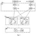
- FIG. 1is a simplified block diagram showing, at a network element level, the most important parts of a radio system. The structure and functions of the network elements are only described when relevant to the present solution.
- a radio access networkcalled UTRAN (UMTS Terrestrial Radio Access Network) 130 is taken as an example.
- UTRANUMTS Terrestrial Radio Access Network
- the network elements of the GSM system not shown in FIG. 1can be implemented as a separate system from UTRAN known as GERAN (GSM/EDGE Radio Access network), or included in the UTRAN infrastructure.
- GSM/EDGE Radio Access networkGSM/EDGE Radio Access network
- the division between the different radio systemsis not relevant to the present solution.
- the solutionis not limited to a WCDMA radio interface but applications exist which are implemented with MC-CDMA (Multi-Carrier Code Division Multiple Access) or OFDMA (Orthogonal Frequency Division Multiple Access) technologies.
- the radio systemcan also be defined to comprise a mobile station and a network part.
- the mobile stationis also called user equipment, a terminal, a subscriber terminal and a mobile telephone.
- the network partcomprises the fixed infrastructure of the radio system, i.e. the core network, radio access network and the base station system.
- the structure of the core network 100corresponds to a system which incorporates both circuit-switched and packet-switched domains. Both domains can utilize the same radio access network 130 .
- a mobile services switching center (MSC) 102is the center point of the circuit-switched side of the core network 100 .
- the mobile services switching center 102is used to serve the connections of the radio access network 130 .
- the tasks of the mobile services switching center 102include: switching, paging, user equipment location registration, handover management, collection of subscriber billing information, encryption parameter management, frequency allocation management, and echo cancellation.
- GMSCgateway mobile services switching center
- PLMNpublic land mobile network
- PSTNpublic switched telephone network
- a serving GPRS support node (SGSN) 118is the center point of the packet-switched side of the core network 100 .
- the main task of the serving GPRS support node 118is to transmit and receive packets together with the mobile station 170 supporting packet-switched transmission by using the radio access network 130 or the base station system.
- the serving GPRS support node 118contains subscriber and location information related to the mobile station 170 .
- a gateway GPRS support node (GGSN) 120is the packet-switched side counterpart to the gateway mobile services switching center 110 of the circuit-switched side with the exception, however, that the gateway GPRS support node 120 must also be capable of routing traffic from the core network 100 to external networks 182 , whereas the gateway mobile services switching center 110 only routes incoming traffic.
- external networks 182are represented by the Internet.
- the radio access network 130comprises radio network subsystems 140 , 150 .
- Each radio network subsystem 140 , 150comprises radio network controllers (RNC) 146 , 156 and nodes B 142 , 144 , 152 , 154 .
- RNCradio network controllers
- Node Bis a rather abstract concept; the terms ‘base transceiver station’ or ‘base station’ are often used instead. In this application Node B is called a base station.
- the base stationprovides the mobile station 170 with radio transmission and reception. Solutions exist in which the base station is capable of implementing both the TDMA and WCDMA radio interfaces simultaneously.
- the mobile station 170provides a user of the mobile station with access to the mobile communication system.
- the mobile stationcomprises two parts: mobile equipment (ME) 172 and a UMTS subscriber identity module (USIM) 174 .
- the GSM systemnaturally uses its own identity module.
- the mobile station 170comprises at least one transceiver for establishing a radio link to the radio access network 130 .
- the mobile station 170may comprise at least two different subscriber identity modules.
- the mobile station 170further comprises an antenna, a user interface and a battery.
- the USIM 174comprises user-related information and information related to information security, such as an encryption algorithm.
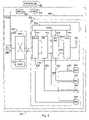
- FIG. 2shows a mobile services switching center 102 , a gateway mobile services switching center 110 , which is responsible for the connections of the mobile communication system to the external world, herein to the public telephone network 180 , and a network part 200 .
- the network part 200comprises a base station 142 controlled by a radio network controller 146 , a group switching field 220 , and a control unit 222 .
- the group switching field 220is used for switching speech and data and for connecting signalling circuits. Solutions exist in which the network controller 146 is implemented in the base station 142 .
- the tasks that the network controller 146 performsinclude, for example: control of logical operations of the base station and maintenance management, traffic management of common channels, handover management, allocation of downlink channelization codes, uplink outer-loop control, load and admission control, and traffic management of shared channels.
- the control unit 222carries out call control, mobility management, collecting statistical data, signalling, and control and management of resources.
- the base station 142 and the radio network controller 146constitute a radio network subsystem 140 , which further comprises a transcoder 226 , which converts different digital speech encoding formats used between a public telephone network and a radio telephone network into compatible ones, e.g. from the format of the fixed network into another format of the cellular radio network, and vice versa.
- a transcoder 226which converts different digital speech encoding formats used between a public telephone network and a radio telephone network into compatible ones, e.g. from the format of the fixed network into another format of the cellular radio network, and vice versa.
- the base station 142comprises a main station 224 and a remote station 240 , 242 , 244 , 246 .
- the remote station 240 , 242 , 244 , 246provides the mobile station with radio transmission and reception, and uses the same radio interface as the main station 224 . Furthermore, the remote station 240 , 242 , 244 , 246 is controlled by the base station 142 , and the traffic of the remote station 240 , 242 , 244 , 246 is routed e.g. to the external networks 180 , 182 via the base station 142 .
- the remote station 240 , 242 , 244 , 246can include all the basic functionalities included in the base station 142 .
- the main station 224comprises a multiplexer unit 212 , a baseband unit 214 , an analog-digital converter unit 216 , a transceiver unit 218 and a control unit 210 .
- the multiplexer unit 212is used for arranging the traffic and control channels used by the transceiver unit 218 onto a single transmission connection 211 . Furthermore, the multiplexer unit 212 carries out error correction operations and, possibly, bit interleaving and de-interleaving.
- the baseband unit 214comprises e.g. a digital signal processor, ASICs (Application-Specific Integrated Circuits), data busses, data storage media, and software, for example, for coding and decoding of signals.
- ASICsApplication-Specific Integrated Circuits
- data bussesdata storage media
- softwarefor example, for coding and decoding of signals.
- the analog-digital converter unit 216comprises A/D (analog-to-digital) and D/A (digital-to-analog) converters for digitizing analog antenna signals and for converting digital antenna signals to analog form.
- the transceiver unit 218comprises e.g. frequency modulators for modulating the baseband signals to the radio frequency and vice versa, and amplifiers for amplifying antenna signals. Furthermore, the transceiver unit 218 comprises e.g. duplex filters for separating the received and transmitted antenna signals from each other.
- the transceiver unit 218is connected to an antenna unit 234 .
- the antenna unit 234is used for implementing a radio connection to a mobile station 170 .
- the antenna unit 234comprises an antenna array for beam forming.
- the antenna unit 234can also comprise leaky cables for forming an elongated radiation pattern.
- the control unit 210controls the operation of the multiplexer unit 212 , baseband unit 214 , analog-to-digital converter unit 216 , the transceiver unit 218 , and the remote station 240 , 242 , 244 , 246 .
- the combination of the multiplexer unit 212 , the baseband unit 214 , the analog-digital converter unit 216 , and the transceiver unit 218constitute at least two collector-distributor routes 236 , 238 for processing transmitted and received signals.
- Each collector-distributor route 236 , 238is capable of independent antenna signal processing, which includes e.g. weighting of the antenna signals and user-specific signals.
- At least one of the collector-distributor routes 236 , 238is dedicated to processing the signals transmitted and received by the antenna unit 234 .
- At least one of the collector-distributor routes 236 , 238deals with the signals transmitted and received by the remote station 240 , 242 , 244 , 246 .
- the details in the set-up of the collector-distributor route 236 , 238depend on the details of the specific embodiment.
- the remote station 240is connected to the transceiver unit 218 of the base station 142 .
- the remote station 240correspondingly, comprises at least an antenna unit 320 .
- the antenna unit 320comprises at least one antenna element for providing the mobile station 170 with radio transmission and reception.
- the antenna unit 320can also comprise an adaptive antenna array, thus enabling beam forming and user-specific antenna beams that can follow the motion of the mobile station 170 .
- the radio frequency analog signalsare transmitted between the main station 224 and the remote station 240 .
- the signalscan be further subjected to amplification and/or filtering in an amplifier-filter unit 322 , which comprises power amplifiers and/or duplex filters, respectively.
- the physical connection 250 between the transceiver unit 218 of the main station 224 and the amplifier-filter unit 322 of the remote station 240can be implemented, for example, with coaxial cables suitable for conducting radio frequency signals.
- the remote station 242is connected to the analog-digital converter unit 216 of the main station 224 .
- the remote station 242correspondingly, comprises the antenna unit 320 and the amplifier-filter unit 322 described above.
- the remote station 242comprises a transceiver unit 330 including similar elements and performing similar tasks to those of the transceiver unit 218 of the main station 224 .
- the maximum output power requirementis substantially lower than that of the main station 224 .
- analog baseband signalsare transmitted between the main station 224 and the remote station 242 .
- the modulation of the base band signals to the radio frequencyis now carried out in the transceiver unit 330 of the remote station 242 .
- connection 252 between the transceiver unit 330 of the remote station 242 and the analog-digital converter unit 216 of the main station 224can be implemented with a galvanic conductor arrangement, such as a coaxial cabling, an optical data transmission, or with a fixed radio link.
- a galvanic conductor arrangementsuch as a coaxial cabling, an optical data transmission, or with a fixed radio link.
- the means for optical data transmission and radio link transmissionare not shown, but their structure and implementation are well known to a person skilled in the art.
- the remote station 244is connected to the base band unit 214 of the main station.
- the remote station 244correspondingly, comprises the antenna unit 320 , the amplifier-filter unit 322 , and the transceiver unit 330 described above.
- the remote station 244comprises an analog-digital converter unit 340 including similar elements and performing similar tasks as the analog-digital converter unit 216 of the main station 224 .
- the connection 254 between the analog-digital converter unit 340 of the remote station 244 and the base band unit 214 of the main station 224can be implemented in the manner described above.
- the remote station 246is connected to the multiplexer unit 212 of the main station 224 .
- the remote station 246correspondingly, comprises the antenna unit 320 , the amplifier-filter unit 322 , the transceiver unit 330 , and the analog-digital converter unit 340 described above.
- the remote station 246comprises a base band unit 350 including similar elements and performing similar tasks to those of the base band unit 212 of the main station 224 .
- the connection 256 between the analog-digital converter unit 340 of the remote station 244 and the base band unit 214 of the main station 224can be implemented e.g. with a galvanic conductor arrangement well known to a person skilled in the art.
- the control unit 210controls the relevant elements 322 , 330 , 340 350 of the remote station 240 , 242 , 244 , 246 .
- the control unit 210controls the transmit power of the remote station 242 , 244 , 246 by adjusting the transceiver unit 330 and possibly the base band unit 350 accordingly.
- the control unit 210deals with handover management, which handover occurs between the cell of the main station 224 and the coverage area of the remote station 240 , 242 , 244 , 246 . In a WCDMA system, such handover is called softer handover.
- the control unit 210is connected to the remote station 240 , 242 , 244 , 246 by the conductor means 260 , such as a coaxial cable.
- the remote station 240 , 242 , 244 , 246comprises a control unit 360 to control local functions of the remote station 240 , 242 , 244 , 246 .
- Such local functionsinclude e.g. power control and associated measurements, load and admission control, and tasks associated with ARQ (Automatic Repeat Request).
- the tasks controlled by the control unit 360can also be sub-functions of the radio network controller 146 .
- FIG. 4shows the base station 142 , the base station control unit 460 , and the mobile station 170 .
- the base station control unit 460deals e.g. with load and admission control, and control of scrambling and channel coding.
- the base station control unit 460can be implemented as a part of the radio network controller 146 .
- the base station 142comprises a main station 224 for forming a cell 410 .
- the main stationmay be connected to the remote station 440 by a connecting means 430 , such as a galvanic or optical link, for example.
- the coverage of the cell 410can vary from dozens of kilometers of the macro cell range to dozens of meters of the pico cell range.
- the cell 410can be, for example, a sectorized cell, and it can include user-specific radiation patterns.
- the remote station 240 , 242 , 244 , 246indicated with a single reference number 440 in FIG. 4 , is configured to form a service site 420 inside the cell 410 , the service site 420 providing the mobile station 170 with higher capacity than the cell 410 .
- the service site 420is a zone wherein the radio transmission and reception of the remote station 440 are available to the mobile station 170 .
- the capacity of the service site 420is based on a short distance, typically of the order of meters, between the remote station 440 and the mobile station thus enabling low transmit power of the order of several nW of both the mobile station 170 and the remote station 440 .
- the capacity allocated by using the service site 440 to a single mobile station 170can be of the order of the capacity of the entire cell 410 or a sector of the cell 410 , and it is primarily limited by the multi-user interference arising from other radio sources in the cell.
- the shape and the size of the service site 420depend on the specific application of the service site 420 . On a general level, the dimensions of the service site 420 are in accordance with the free path of the mobile station 170 connected to the remote station 440 .
- the free path of the mobile station 170can be defined as a space taken by the user during the connection to the remote station 420 .
- the operating range of the service site 420can be as short as half a meter.
- the corresponding transmit powercan vary from 1 nW to 10 nW.
- a prolate shape of the service site 420can be applied and the operating range can be as long as 50 meters, corresponding to a transmit power of the order of 1 ⁇ W.
- the desired shape of the radiation patterncan be obtained with antenna beam techniques or leaky cables used as an antenna. The characteristics described above give rise to the term “femto cell” used for the service site 420 .
- the operating range of the service site 420is confined to a line-of-sight range from the remote station 440 , thus enabling good quality of the communication channel.
- the good quality of the communication channelgives rise to reduced signalling, reduced retransmitting, and efficiency in channel coding.
- the operating range of the service site 420is based on a channel estimate produced by the base station 142 or by the mobile station 170 .
- the channel estimatecan be e.g. SINR (Signal-to-Interference+Noise Ratio), which characterizes the quality of the radio channel and from which the information transfer capacity can be further derived. If the channel meets the desired capacity requirement and if the multi-user interference generated by the remote station 440 in the cell 410 is acceptable, the connection between the mobile station 170 and the service site 440 can be established.
- SINRSignal-to-Interference+Noise Ratio
- the service site 420uses a different physical radio channel from that used in the cell 410 .
- the separation between the physical radio channelscan be achieved by using different multiple access methods.
- the radio channelscan be implemented with different codes used by the service site 420 and the cell 410 .
- the physical channelscan also be identified by different carrier frequencies, which is characteristic of FDMA (Frequency Division Multiple accees) based methods.
- the channelscan also be separated by using different time-slots, which is characteristic, for instance, of TDMA (Time Division Multiple Access) methods, which further apply different frequency bands to separate signals between different sectors.
- multiplexingcan be based on a combination of the aforementioned methods. However, the multiplexing scheme irrelevant to the present solution.
- the operation and usage of the service site 440will be discussed in the following.
- the examples shownare limited to an operation with a single mobile station 170 , but the examples also apply to cases wherein two or more mobile stations 170 communicate with the service site 420 simultaneously.
- the basic idea of the operation of the service site 420is illustrated in a flow diagram shown in FIG. 5 .
- the mobile station 170may be situated with in the coverage of the cell 410 and connected 510 to the main station 224 of the base station 142 .
- the mobile station 170can transfer information with the main station 224 , or be in an idle mode.
- the procedurecontinues with a request 520 for allocation of information transfer capacity to the mobile station 170 .
- the requestis directed to the base station control unit 460 , which deals with the radio resource control of the cell 410 and the service site 420 .
- the mobile station 170detects, before requesting for allocation of information transfer capacity to the mobile station 170 , a need for allocating information transfer capacity to the mobile station 170 .
- the detectioncan arise, for example, from data reception or transmission.
- the request for allocating capacitycan also be generated in the base station control unit 460 if there is a need to decrease the load of the cell 410 .
- the base station control unit 460suggests a suitable mobile station 170 to enter the service site 420 , and the radio resources of the mobile station 170 will be released for other users in the cell.
- the mobile station 170After requesting 520 allocation of capacity to the mobile station 170 , the mobile station 170 is connected 530 to the service site by forming a radio connection with the remote station 440 .
- the connection between the remote station 440 and the mobile stationcan be established with a softer-hand over procedure controlled by the control unit 210 of the base station 142 .
- the mobile station 170in the transition phase, is connected both to the main station 224 and to the remote station 440 using the same scrambling code.
- the signals from the main station 224 and the remote stationcan be distinguished by generating an artificial delay in the signal of the remote station followed by a change in the scrambling code used by the remote station 440 .
- the command to change the scrambling codecan be generated in the base station control unit 460 , and delivered to the mobile station by the control channels, such as the random access channel (RACH) according to the 3G specification.
- the control channelssuch as the random access channel (RACH) according to the 3G specification.
- the transmit power of the mobile station 170is decreased to a predetermined level, after the mobile station 170 has been connected to the service site 420 .
- the predetermined power levelis lower than a normal minimum transmit power defined in the radio system. For example in the 3G specifications, the minimum transmit power of the mobile station is ⁇ 50 dBm corresponding to 10 nW.
- the low transmit powerreduces the multi-user interference in the cell 410 , and it can be used when short distance exists between the mobile station 170 and the remote station 440 .
- the power control commandcan be given by the base station control unit 460 , or it can be generated by the mobile station 170 itself.
- the transmit power of the remote station 440is controlled according to the information transfer capacity requirement of the mobile station 170 . For example, if the signals from the cell 410 give rise to an increase in the multi-user interference, the power of the remote station 440 can be increased.
- the mobile station 170is connected to the service site 420 based on an intentional act of the user of the mobile station 170 to use the service site 420 .
- the intentional actcomprises e.g. entering the service site 420 or switching on a specific application in the mobile station 170 , the application requiring high capacity. Consequently, it is preferred, that the location information on the service site 420 is known to the user a priori.
- the location informationcan be delivered to the user with visual signs 450 , which can be used to show the exact location of the service site 420 and which can further guide the user to the proximity of the service site 420 .
- a visual sign 450is an identifier, such as a signboard by which the user can identify the service site 420 .
- the mobile station 170is connected to the service site 420 whenever the mobile station 170 is located within the operating range of the service site 420 and whenever there is a request for a capacity allocation to the mobile station 170 . Also, in an embodiment, the mobile station 170 is disconnected 560 from the service site 420 whenever the mobile station 170 is located outside the operation range of the service site 420 . The mobile station 170 can also be disconnected 560 from the service site 420 whenever the data transfer between the remote station 440 and the mobile station 170 is completed. After the mobile station 170 has been disconnected 560 from the service site 420 , the mobile station 170 can be reconnected to the cell 410 of the base station 142 or it can be switched off.
- the location of the mobile station 170is determined based, for example, on a direction-of-arrival (DoA) estimate of the mobile station.
- DoAcan be generated in the base station control unit 460 based on the signals received from the mobile station 170 as is known to a person skilled in the art.
- the remote station 440is located in a fixed position, the location of the service site 420 is known a priori to the base station 142 , and it is a matter of trivial calculation to obtain the relative position of the mobile station 170 and the service site 420 .
- the positioning of the mobile station 170can also be based on measurements carried out by at least two base stations on the direction of the mobile station 170 .
- the location determination of the mobile station 170can also be based on positioning systems available to public, such as GPS (Global Positioning System).
- GPSGlobal Positioning System
- the mobile equipmentitself has elements for generating the location information or it is attached to specific equipment for that purpose.
- the mobile station 170is provided with accessibility information on the service site 440 .
- the accessibility informationcomprises e.g. the data transfer capacity available in the service site 420 , and the information whether or not the specific service site 440 is reserved for another user.
- the accessibility informationcan be produced and processed in the base station control unit 460 , and transferred to the mobile station 170 by means of the control channels of the radio system.
- the mobile station 170is provided with guidance information to the service site 420 .
- the guidance informationcomprises the location of the nearby service sites 420 relative to the position of the mobile station 170 , and possibly instructions for finding a service site 420 .
- the guidance informationcan be produced and processed in the base station control unit 460 , but it can be downloaded to and stored in the mobile station as well.
- the mobile station 170is provided with means for indicating the location information on the service site 420 .
- the mobile stationcan display a map of the relevant area, which includes an indication of the direction of the service site 420 and other relevant information necessary for finding it.
- a single base station 142can comprise several remote stations 440 , each of which forms a service site 420 . It is believed that especially in the urban areas, the remote stations 440 can form a web-like structure, the distance between the service sites 420 being the order of the range of line-of-sight. Suitable locations of the service sites 420 also include places where the radio interference is a severe problem, such as hospitals.
- the remote stations 440can also be arranged along a highway to provide spot-like high capacity areas, which become available to a user whenever the user enters such an area. This arrangement can be applied if the user is satisfied with burst-like capacity peaks for data transfer. This is possible due to the softer handover procedure applied in the present solution when the connection is interchanged between the cell 410 and the service site 420 .
- the remote station 440can utilize beam forming in transmission and reception, wherein antenna beams are aimed along a road alignment and possible at the vehicles driving on the highway.
- Leaky cables installed along the road alignmentcan also be utilized to form an elongated radiation pattern that covers the vehicles driving on the highway. In such a case, the operating range of the service site 420 is in the order of the width of the highway, which is of the order of dozens of meters.
Landscapes
- Engineering & Computer Science (AREA)
- Computer Networks & Wireless Communication (AREA)
- Signal Processing (AREA)
- Mobile Radio Communication Systems (AREA)
Abstract
Description
Claims (44)
Applications Claiming Priority (1)
| Application Number | Priority Date | Filing Date | Title |
|---|---|---|---|
| PCT/FI2002/000603WO2004006602A1 (en) | 2002-07-03 | 2002-07-03 | Method for allocating information transfer capacity in mobile communication system, and mobile communication system |
Publications (2)
| Publication Number | Publication Date |
|---|---|
| US20050002353A1 US20050002353A1 (en) | 2005-01-06 |
| US7277410B2true US7277410B2 (en) | 2007-10-02 |
Family
ID=38610521
Family Applications (1)
| Application Number | Title | Priority Date | Filing Date |
|---|---|---|---|
| US10/611,680Expired - LifetimeUS7277410B2 (en) | 2002-07-03 | 2003-07-02 | Method for allocating information transfer capacity in mobile communication system, and mobile communication system |
Country Status (3)
| Country | Link |
|---|---|
| US (1) | US7277410B2 (en) |
| AU (1) | AU2002345137A1 (en) |
| WO (1) | WO2004006602A1 (en) |
Cited By (11)
| Publication number | Priority date | Publication date | Assignee | Title |
|---|---|---|---|---|
| US20090280819A1 (en)* | 2008-05-07 | 2009-11-12 | At&T Mobility Ii Llc | Femto cell signaling gating |
| US20090280853A1 (en)* | 2008-05-07 | 2009-11-12 | At&T Mobility Ii Llc | Signaling-triggered power adjustment in a femto cell |
| US20090286510A1 (en)* | 2008-05-13 | 2009-11-19 | At&T Mobility Il Llc | Location-based services in a femtocell network |
| US20100027469A1 (en)* | 2008-06-12 | 2010-02-04 | At&T Mobility Ii Llc | Point of sales and customer support for femtocell service and equipment |
| US20100167732A1 (en)* | 2008-12-30 | 2010-07-01 | Motorola, Inc. | Providing over-the-top services on femto cells of an ip edge convergence server system |
| US20100167740A1 (en)* | 2008-12-30 | 2010-07-01 | Motorola, Inc. | Wide area mobile communications over femto-cells |
| US20100272024A1 (en)* | 2005-10-21 | 2010-10-28 | At&T Intellectual Property I, L.P. | Intelligent pico-cell for transport of wireless device communications over wireline networks |
| US20110093913A1 (en)* | 2009-10-15 | 2011-04-21 | At&T Intellectual Property I, L.P. | Management of access to service in an access point |
| US8326296B1 (en) | 2006-07-12 | 2012-12-04 | At&T Intellectual Property I, L.P. | Pico-cell extension for cellular network |
| US8670764B2 (en) | 2010-12-08 | 2014-03-11 | Industrial Technology Research Institute | Wireless communication systems and methods for processing handover messages thereof and computer program products thereof |
| US8719420B2 (en) | 2008-05-13 | 2014-05-06 | At&T Mobility Ii Llc | Administration of access lists for femtocell service |
Families Citing this family (14)
| Publication number | Priority date | Publication date | Assignee | Title |
|---|---|---|---|---|
| US8583100B2 (en) | 2007-01-25 | 2013-11-12 | Adc Telecommunications, Inc. | Distributed remote base station system |
| US8737454B2 (en) | 2007-01-25 | 2014-05-27 | Adc Telecommunications, Inc. | Modular wireless communications platform |
| EP2071881A1 (en)* | 2007-12-11 | 2009-06-17 | Nokia Siemens Networks Oy | Method and device for processing and providing handover information by a network and communications system comprising such device |
| WO2010064245A2 (en)* | 2008-12-04 | 2010-06-10 | Greenair Wireless Ltd. | Signal strength reducing communication system, device, and method |
| US8175538B1 (en) | 2008-12-15 | 2012-05-08 | Qualcomm Atheros, Inc. | Calibrating a wireless communication device |
| US8295263B1 (en) | 2009-02-06 | 2012-10-23 | Qualcomm Atheros, Inc. | Triggering and transmitting sounding packets for wireless communications |
| US8804612B1 (en)* | 2009-02-06 | 2014-08-12 | Qualcomm Incorporated | Triggering and transmitting sounding packets for wireless communications |
| US8428602B2 (en)* | 2009-10-14 | 2013-04-23 | Ntt Docomo, Inc. | Methods for enhancing performance of open-access and closed-access femtocells |
| US8666382B2 (en)* | 2010-04-28 | 2014-03-04 | Tango Networks, Inc. | Controlling mobile device calls, text messages and data usage while operating a motor vehicle |
| US8705503B2 (en) | 2010-11-22 | 2014-04-22 | At&T Intellectual Property I, L.P. | Apparatus and method of automatically provisioning a femtocell |
| US9374717B2 (en)* | 2012-03-19 | 2016-06-21 | Qualcomm Incorporated | Transmitting indication of access point loading |
| US9300458B2 (en)* | 2013-02-05 | 2016-03-29 | Cable Television Laboratories, Inc. | Transmission opportunity scheduling |
| US10499269B2 (en) | 2015-11-12 | 2019-12-03 | Commscope Technologies Llc | Systems and methods for assigning controlled nodes to channel interfaces of a controller |
| US11428094B2 (en)* | 2020-05-16 | 2022-08-30 | Interface, Inc. | Wireless load cell monitoring system and method |
Citations (10)
| Publication number | Priority date | Publication date | Assignee | Title |
|---|---|---|---|---|
| WO2001063851A1 (en) | 2000-02-21 | 2001-08-30 | Nokia Corporation | Capacity allocation for packet data bearers |
| WO2001074096A2 (en) | 2000-03-27 | 2001-10-04 | Soma Networks, Inc. | Wireless local loop |
| WO2002017107A1 (en) | 2000-08-24 | 2002-02-28 | Comsat Corporation | Dynamic allocation of network resources in a multiple-user communication system |
| EP1217852A1 (en) | 2000-12-22 | 2002-06-26 | NTT DoCoMo, Inc. | Radio resource allocation method and base station using the same |
| US20020136174A1 (en)* | 2001-03-21 | 2002-09-26 | Gleeson John K. | Communication device having proximity controlled transmission |
| US6865169B1 (en)* | 1999-11-02 | 2005-03-08 | Ipwireless, Inc. | Cellular wireless internet access system using spread spectrum and internet protocol |
| US6889050B1 (en)* | 2000-11-22 | 2005-05-03 | Telefonaktiebolaget Lm Ericsson (Publ) | Variable transmission rate services in a radio access network |
| US6915131B2 (en)* | 1999-12-06 | 2005-07-05 | Canon Kabushiki Kaisha | Communicating apparatus, communication system, communicating method, and storage medium |
| US6983162B2 (en)* | 2001-09-14 | 2006-01-03 | Motorola, Inc. | Method for enhancing the communication capability in a wireless telecommunication system |
| US7072661B2 (en)* | 2002-06-03 | 2006-07-04 | Lucent Technologies Inc. | Wireless communications system and related methods for allocating data transmission |
Family Cites Families (5)
| Publication number | Priority date | Publication date | Assignee | Title |
|---|---|---|---|---|
| GB2295524A (en)* | 1994-11-28 | 1996-05-29 | Northern Telecom Ltd | Beamed antenna system for a cellular radio base station |
| US5946612A (en)* | 1997-03-28 | 1999-08-31 | Telefonaktiebolaget L M Ericsson (Publ) | Method and apparatus for performing local traffic measurements in a cellular telephone network |
| EP1079544A1 (en)* | 1999-08-20 | 2001-02-28 | Alcatel | CDMA mobile radio system |
| JP3567980B2 (en)* | 2000-06-13 | 2004-09-22 | 日本電気株式会社 | Transmission capacity control method and mobile communication system |
| US6580899B1 (en)* | 2000-09-07 | 2003-06-17 | Nortel Networks Limited | Adaptive forward power management algorithm for traffic hotspots |
- 2002
- 2002-07-03AUAU2002345137Apatent/AU2002345137A1/ennot_activeAbandoned
- 2002-07-03WOPCT/FI2002/000603patent/WO2004006602A1/ennot_activeApplication Discontinuation
- 2003
- 2003-07-02USUS10/611,680patent/US7277410B2/ennot_activeExpired - Lifetime
Patent Citations (10)
| Publication number | Priority date | Publication date | Assignee | Title |
|---|---|---|---|---|
| US6865169B1 (en)* | 1999-11-02 | 2005-03-08 | Ipwireless, Inc. | Cellular wireless internet access system using spread spectrum and internet protocol |
| US6915131B2 (en)* | 1999-12-06 | 2005-07-05 | Canon Kabushiki Kaisha | Communicating apparatus, communication system, communicating method, and storage medium |
| WO2001063851A1 (en) | 2000-02-21 | 2001-08-30 | Nokia Corporation | Capacity allocation for packet data bearers |
| WO2001074096A2 (en) | 2000-03-27 | 2001-10-04 | Soma Networks, Inc. | Wireless local loop |
| WO2002017107A1 (en) | 2000-08-24 | 2002-02-28 | Comsat Corporation | Dynamic allocation of network resources in a multiple-user communication system |
| US6889050B1 (en)* | 2000-11-22 | 2005-05-03 | Telefonaktiebolaget Lm Ericsson (Publ) | Variable transmission rate services in a radio access network |
| EP1217852A1 (en) | 2000-12-22 | 2002-06-26 | NTT DoCoMo, Inc. | Radio resource allocation method and base station using the same |
| US20020136174A1 (en)* | 2001-03-21 | 2002-09-26 | Gleeson John K. | Communication device having proximity controlled transmission |
| US6983162B2 (en)* | 2001-09-14 | 2006-01-03 | Motorola, Inc. | Method for enhancing the communication capability in a wireless telecommunication system |
| US7072661B2 (en)* | 2002-06-03 | 2006-07-04 | Lucent Technologies Inc. | Wireless communications system and related methods for allocating data transmission |
Cited By (71)
| Publication number | Priority date | Publication date | Assignee | Title |
|---|---|---|---|---|
| US20100272024A1 (en)* | 2005-10-21 | 2010-10-28 | At&T Intellectual Property I, L.P. | Intelligent pico-cell for transport of wireless device communications over wireline networks |
| US8208431B2 (en) | 2005-10-21 | 2012-06-26 | At&T Intellectual Property I, Lp | Intelligent pico-cell for transport of wireless device communications over wireline networks |
| US10149126B2 (en) | 2006-07-12 | 2018-12-04 | At&T Intellectual Property I, L.P. | Pico-cell extension for cellular network |
| US9674679B2 (en) | 2006-07-12 | 2017-06-06 | At&T Intellectual Property I, L.P. | Pico-cell extension for cellular network |
| US9301113B2 (en) | 2006-07-12 | 2016-03-29 | At&T Intellectual Property I, L.P. | Pico-cell extension for cellular network |
| US8897752B2 (en) | 2006-07-12 | 2014-11-25 | At&T Intellectual Property I, L.P. | Pico-cell extension for cellular network |
| US8326296B1 (en) | 2006-07-12 | 2012-12-04 | At&T Intellectual Property I, L.P. | Pico-cell extension for cellular network |
| US20090280853A1 (en)* | 2008-05-07 | 2009-11-12 | At&T Mobility Ii Llc | Signaling-triggered power adjustment in a femto cell |
| US8812049B2 (en) | 2008-05-07 | 2014-08-19 | At&T Mobility Ii Llc | Femto cell signaling gating |
| US8626223B2 (en) | 2008-05-07 | 2014-01-07 | At&T Mobility Ii Llc | Femto cell signaling gating |
| US20090280819A1 (en)* | 2008-05-07 | 2009-11-12 | At&T Mobility Ii Llc | Femto cell signaling gating |
| US8126496B2 (en) | 2008-05-07 | 2012-02-28 | At&T Mobility Ii Llc | Signaling-triggered power adjustment in a femto cell |
| US8522312B2 (en) | 2008-05-13 | 2013-08-27 | At&T Mobility Ii Llc | Access control lists and profiles to manage femto cell coverage |
| US8763082B2 (en) | 2008-05-13 | 2014-06-24 | At&T Mobility Ii Llc | Interactive client management of an access control list |
| US10499247B2 (en) | 2008-05-13 | 2019-12-03 | At&T Mobility Ii Llc | Administration of access lists for femtocell service |
| US10225733B2 (en) | 2008-05-13 | 2019-03-05 | At&T Mobility Ii Llc | Exchange of access control lists to manage femto cell coverage |
| US20090286510A1 (en)* | 2008-05-13 | 2009-11-19 | At&T Mobility Il Llc | Location-based services in a femtocell network |
| US8082353B2 (en) | 2008-05-13 | 2011-12-20 | At&T Mobility Ii Llc | Reciprocal addition of attribute fields in access control lists and profiles for femto cell coverage management |
| US8094551B2 (en) | 2008-05-13 | 2012-01-10 | At&T Mobility Ii Llc | Exchange of access control lists to manage femto cell coverage |
| US9930526B2 (en) | 2008-05-13 | 2018-03-27 | At&T Mobility Ii Llc | Interface for access management of femto cell coverage |
| US9877195B2 (en) | 2008-05-13 | 2018-01-23 | At&T Mobility Ii Llc | Location-based services in a femtocell network |
| US20100027521A1 (en)* | 2008-05-13 | 2010-02-04 | At&T Mobility Ii Llc | Intra-premises content and equipment management in a femtocell network |
| US8179847B2 (en) | 2008-05-13 | 2012-05-15 | At&T Mobility Ii Llc | Interactive white list prompting to share content and services associated with a femtocell |
| US8209745B2 (en) | 2008-05-13 | 2012-06-26 | At&T Mobility Ii Llc | Automatic population of an access control list to manage femto cell coverage |
| US9775036B2 (en) | 2008-05-13 | 2017-09-26 | At&T Mobility Ii Llc | Access control lists and profiles to manage femto cell coverage |
| US8219094B2 (en) | 2008-05-13 | 2012-07-10 | At&T Mobility Ii Llc | Location-based services in a femtocell network |
| US8254368B2 (en) | 2008-05-13 | 2012-08-28 | At&T Mobility Ii Llc | Femtocell architecture for information management |
| US8274958B2 (en) | 2008-05-13 | 2012-09-25 | At&T Mobility Ii Llc | Intra-premises content and equipment management in a femtocell network |
| US20090288152A1 (en)* | 2008-05-13 | 2009-11-19 | At&T Mobility Ii Llc | Automatic population of an access control list to manage femto cell coverage |
| US8331228B2 (en) | 2008-05-13 | 2012-12-11 | At&T Mobility Ii Llc | Exchange of access control lists to manage femto cell coverage |
| US8463296B2 (en) | 2008-05-13 | 2013-06-11 | At&T Mobility Ii Llc | Location-based services in a femtocell network |
| US8490156B2 (en) | 2008-05-13 | 2013-07-16 | At&T Mobility Ii Llc | Interface for access management of FEMTO cell coverage |
| US9775037B2 (en) | 2008-05-13 | 2017-09-26 | At&T Mobility Ii Llc | Intra-premises content and equipment management in a femtocell network |
| US20090286509A1 (en)* | 2008-05-13 | 2009-11-19 | At&T Mobility Ii Llc | Reciprocal addition of attribute fields in access control lists and profiles for femto cell coverage management |
| US20090288140A1 (en)* | 2008-05-13 | 2009-11-19 | At&T Mobility Ii Llc | Access control lists and profiles to manage femto cell coverage |
| US20090285166A1 (en)* | 2008-05-13 | 2009-11-19 | At&T Mobility Ii Llc | Interactive white list prompting to share content and services associated with a femtocell |
| US9591486B2 (en) | 2008-05-13 | 2017-03-07 | At&T Mobility Ii Llc | Intra-premises content and equipment management in a femtocell network |
| US9584984B2 (en) | 2008-05-13 | 2017-02-28 | At&T Mobility Ii Llc | Reciprocal addition of attribute fields in access control lists and profiles for femto cell coverage management |
| US8719420B2 (en) | 2008-05-13 | 2014-05-06 | At&T Mobility Ii Llc | Administration of access lists for femtocell service |
| US9538383B2 (en) | 2008-05-13 | 2017-01-03 | At&T Mobility Ii Llc | Interface for access management of femto cell coverage |
| US8755820B2 (en) | 2008-05-13 | 2014-06-17 | At&T Mobility Ii Llc | Location-based services in a femtocell network |
| US9503457B2 (en) | 2008-05-13 | 2016-11-22 | At&T Mobility Ii Llc | Administration of access lists for femtocell service |
| US8787342B2 (en) | 2008-05-13 | 2014-07-22 | At&T Mobility Ii Llc | Intra-premises content and equipment management in a femtocell network |
| US20090288144A1 (en)* | 2008-05-13 | 2009-11-19 | At&T Mobility Ii Llc | Time-dependent white list generation |
| US8850048B2 (en) | 2008-05-13 | 2014-09-30 | At&T Mobility Ii Llc | Reciprocal addition of attribute fields in access control lists and profiles for femto cell coverage management |
| US9392461B2 (en) | 2008-05-13 | 2016-07-12 | At&T Mobility Ii Llc | Access control lists and profiles to manage femto cell coverage |
| US8863235B2 (en) | 2008-05-13 | 2014-10-14 | At&T Mobility Ii Llc | Time-dependent white list generation |
| US20090286540A1 (en)* | 2008-05-13 | 2009-11-19 | At&T Mobility Ii Llc | Femtocell architecture for information management |
| US9369876B2 (en) | 2008-05-13 | 2016-06-14 | At&T Mobility Ii Llc | Location-based services in a femtocell network |
| US9019819B2 (en) | 2008-05-13 | 2015-04-28 | At&T Mobility Ii Llc | Exchange of access control lists to manage femto cell coverage |
| US9094891B2 (en) | 2008-05-13 | 2015-07-28 | At&T Mobility Ii Llc | Location-based services in a femtocell network |
| US9155022B2 (en) | 2008-05-13 | 2015-10-06 | At&T Mobility Ii Llc | Interface for access management of FEMTO cell coverage |
| US9319964B2 (en) | 2008-05-13 | 2016-04-19 | At&T Mobility Ii Llc | Exchange of access control lists to manage femto cell coverage |
| US20090286512A1 (en)* | 2008-05-13 | 2009-11-19 | At&T Mobility Ii Llc | Exchange of access control lists to manage femto cell coverage |
| US8942180B2 (en) | 2008-06-12 | 2015-01-27 | At&T Mobility Ii Llc | Point of sales and customer support for femtocell service and equipment |
| US9246759B2 (en) | 2008-06-12 | 2016-01-26 | At&T Mobility Ii Llc | Point of sales and customer support for femtocell service and equipment |
| US8743776B2 (en)* | 2008-06-12 | 2014-06-03 | At&T Mobility Ii Llc | Point of sales and customer support for femtocell service and equipment |
| US20100041364A1 (en)* | 2008-06-12 | 2010-02-18 | At&T Mobility Ii Llc | Femtocell service registration, activation, and provisioning |
| US8655361B2 (en) | 2008-06-12 | 2014-02-18 | At&T Mobility Ii Llc | Femtocell service registration, activation, and provisioning |
| US8504032B2 (en) | 2008-06-12 | 2013-08-06 | At&T Intellectual Property I, L.P. | Femtocell service registration, activation, and provisioning |
| US20100027469A1 (en)* | 2008-06-12 | 2010-02-04 | At&T Mobility Ii Llc | Point of sales and customer support for femtocell service and equipment |
| US8121600B2 (en) | 2008-12-30 | 2012-02-21 | Motorola Mobility, Inc. | Wide area mobile communications over femto-cells |
| US20100167740A1 (en)* | 2008-12-30 | 2010-07-01 | Motorola, Inc. | Wide area mobile communications over femto-cells |
| US20100167732A1 (en)* | 2008-12-30 | 2010-07-01 | Motorola, Inc. | Providing over-the-top services on femto cells of an ip edge convergence server system |
| US8107956B2 (en) | 2008-12-30 | 2012-01-31 | Motorola Mobility, Inc. | Providing over-the-top services on femto cells of an IP edge convergence server system |
| US9509701B2 (en) | 2009-10-15 | 2016-11-29 | At&T Intellectual Property I, L.P. | Management of access to service in an access point |
| US8510801B2 (en) | 2009-10-15 | 2013-08-13 | At&T Intellectual Property I, L.P. | Management of access to service in an access point |
| US20110093913A1 (en)* | 2009-10-15 | 2011-04-21 | At&T Intellectual Property I, L.P. | Management of access to service in an access point |
| US8856878B2 (en) | 2009-10-15 | 2014-10-07 | At&T Intellectual Property I, L.P | Management of access to service in an access point |
| US10645582B2 (en) | 2009-10-15 | 2020-05-05 | At&T Intellectual Property I, L.P. | Management of access to service in an access point |
| US8670764B2 (en) | 2010-12-08 | 2014-03-11 | Industrial Technology Research Institute | Wireless communication systems and methods for processing handover messages thereof and computer program products thereof |
Also Published As
| Publication number | Publication date |
|---|---|
| AU2002345137A1 (en) | 2004-01-23 |
| WO2004006602A1 (en) | 2004-01-15 |
| US20050002353A1 (en) | 2005-01-06 |
Similar Documents
| Publication | Publication Date | Title |
|---|---|---|
| US7277410B2 (en) | Method for allocating information transfer capacity in mobile communication system, and mobile communication system | |
| US6078815A (en) | Method and apparatus for allocating radio channels | |
| US7502614B2 (en) | Radio communication system, radio communication apparatus and radio communication method, and computer program | |
| JP3058261B2 (en) | CDMA handoff system, mobile communication cellular system using the same, and base station thereof | |
| US6246886B1 (en) | System and methods for controlling access to digital wireless network in a dual mode wireless system | |
| US7085570B2 (en) | Handover method, system and radio network controller | |
| AU770733B2 (en) | Method for improving handovers between mobile communication systems | |
| US20070287469A1 (en) | Spectrum utilization in a radio system | |
| EP1108338B1 (en) | Mobile terminal initiated and assisted antenna selection | |
| AU765917B2 (en) | Method and system for improving network resource utilization in a cellular communication system | |
| WO2015082252A2 (en) | Selecting a cell of a wireless cellular communication network | |
| AU1639700A (en) | Method of making downlink operational measurements in a wireless communication system | |
| JPH09247079A (en) | Band division type CDMA system and transmission / reception device | |
| KR0159320B1 (en) | Method and apparatus for a radio remote repeater in a digital cellular radio communication system | |
| AU2003238129B2 (en) | Data transmission method and arrangement | |
| US6081719A (en) | Layered wireless communication system and method | |
| Alencar et al. | Mobile Cellular Telephony | |
| AU9352798A (en) | Method for improving radio connection quality in radio system | |
| KR100663193B1 (en) | Beacon for Hard Handoff | |
| EP0885539B1 (en) | Device and method for dynamic optimization of the transmission capacity in a cellular radio communications system | |
| EP0926914B1 (en) | Methodology of reducing areas with multiple dominant pilots by installing simulcasting elements or omni-directional base station | |
| AU2005251343B2 (en) | A wireless communications network and method of operation thereof | |
| JP2002369244A (en) | Small-capacity base station control system for cdma mobile communication system, and method therefor | |
| WO2003013171A1 (en) | Method for implementing service in radio system, user equipment of radio system, and radio system | |
| KR20100020350A (en) | Repeater apparatus for supporting a plurality of networks |
Legal Events
| Date | Code | Title | Description |
|---|---|---|---|
| AS | Assignment | Owner name:NOKIA CORPORATION, FINLAND Free format text:ASSIGNMENT OF ASSIGNORS INTEREST;ASSIGNOR:HORNEMAN, KARI;REEL/FRAME:015039/0589 Effective date:20030912 | |
| STCF | Information on status: patent grant | Free format text:PATENTED CASE | |
| FEPP | Fee payment procedure | Free format text:PAYOR NUMBER ASSIGNED (ORIGINAL EVENT CODE: ASPN); ENTITY STATUS OF PATENT OWNER: LARGE ENTITY | |
| AS | Assignment | Owner name:NOKIA SIEMENS NETWORKS OY, FINLAND Free format text:ASSIGNMENT OF ASSIGNORS INTEREST;ASSIGNOR:NOKIA CORPORATION;REEL/FRAME:020550/0001 Effective date:20070913 Owner name:NOKIA SIEMENS NETWORKS OY,FINLAND Free format text:ASSIGNMENT OF ASSIGNORS INTEREST;ASSIGNOR:NOKIA CORPORATION;REEL/FRAME:020550/0001 Effective date:20070913 | |
| FPAY | Fee payment | Year of fee payment:4 | |
| AS | Assignment | Owner name:ACACIA RESEARCH GROUP LLC, TEXAS Free format text:ASSIGNMENT OF ASSIGNORS INTEREST;ASSIGNOR:NOKIA SIEMENS NETWORKS OY;REEL/FRAME:033449/0492 Effective date:20130221 Owner name:CELLULAR COMMUNICATIONS EQUIPMENT LLC, TEXAS Free format text:ASSIGNMENT OF ASSIGNORS INTEREST;ASSIGNOR:ACACIA RESEARCH GROUP LLC;REEL/FRAME:033449/0514 Effective date:20130125 | |
| FPAY | Fee payment | Year of fee payment:8 | |
| FEPP | Fee payment procedure | Free format text:11.5 YR SURCHARGE- LATE PMT W/IN 6 MO, LARGE ENTITY (ORIGINAL EVENT CODE: M1556); ENTITY STATUS OF PATENT OWNER: LARGE ENTITY | |
| MAFP | Maintenance fee payment | Free format text:PAYMENT OF MAINTENANCE FEE, 12TH YEAR, LARGE ENTITY (ORIGINAL EVENT CODE: M1553); ENTITY STATUS OF PATENT OWNER: LARGE ENTITY Year of fee payment:12 | |
| AS | Assignment | Owner name:STARBOARD VALUE INTERMEDIATE FUND LP, AS COLLATERAL AGENT, NEW YORK Free format text:PATENT SECURITY AGREEMENT;ASSIGNORS:ACACIA RESEARCH GROUP LLC;AMERICAN VEHICULAR SCIENCES LLC;BONUTTI SKELETAL INNOVATIONS LLC;AND OTHERS;REEL/FRAME:052853/0153 Effective date:20200604 | |
| AS | Assignment | Owner name:NEXUS DISPLAY TECHNOLOGIES LLC, TEXAS Free format text:RELEASE OF SECURITY INTEREST IN PATENTS;ASSIGNOR:STARBOARD VALUE INTERMEDIATE FUND LP;REEL/FRAME:053654/0254 Effective date:20200630 Owner name:INNOVATIVE DISPLAY TECHNOLOGIES LLC, TEXAS Free format text:RELEASE OF SECURITY INTEREST IN PATENTS;ASSIGNOR:STARBOARD VALUE INTERMEDIATE FUND LP;REEL/FRAME:053654/0254 Effective date:20200630 Owner name:CELLULAR COMMUNICATIONS EQUIPMENT LLC, TEXAS Free format text:RELEASE OF SECURITY INTEREST IN PATENTS;ASSIGNOR:STARBOARD VALUE INTERMEDIATE FUND LP;REEL/FRAME:053654/0254 Effective date:20200630 Owner name:AMERICAN VEHICULAR SCIENCES LLC, TEXAS Free format text:RELEASE OF SECURITY INTEREST IN PATENTS;ASSIGNOR:STARBOARD VALUE INTERMEDIATE FUND LP;REEL/FRAME:053654/0254 Effective date:20200630 Owner name:LIFEPORT SCIENCES LLC, TEXAS Free format text:RELEASE OF SECURITY INTEREST IN PATENTS;ASSIGNOR:STARBOARD VALUE INTERMEDIATE FUND LP;REEL/FRAME:053654/0254 Effective date:20200630 Owner name:R2 SOLUTIONS LLC, TEXAS Free format text:RELEASE OF SECURITY INTEREST IN PATENTS;ASSIGNOR:STARBOARD VALUE INTERMEDIATE FUND LP;REEL/FRAME:053654/0254 Effective date:20200630 Owner name:TELECONFERENCE SYSTEMS LLC, TEXAS Free format text:RELEASE OF SECURITY INTEREST IN PATENTS;ASSIGNOR:STARBOARD VALUE INTERMEDIATE FUND LP;REEL/FRAME:053654/0254 Effective date:20200630 Owner name:MONARCH NETWORKING SOLUTIONS LLC, CALIFORNIA Free format text:RELEASE OF SECURITY INTEREST IN PATENTS;ASSIGNOR:STARBOARD VALUE INTERMEDIATE FUND LP;REEL/FRAME:053654/0254 Effective date:20200630 Owner name:UNIFICATION TECHNOLOGIES LLC, TEXAS Free format text:RELEASE OF SECURITY INTEREST IN PATENTS;ASSIGNOR:STARBOARD VALUE INTERMEDIATE FUND LP;REEL/FRAME:053654/0254 Effective date:20200630 Owner name:PARTHENON UNIFIED MEMORY ARCHITECTURE LLC, TEXAS Free format text:RELEASE OF SECURITY INTEREST IN PATENTS;ASSIGNOR:STARBOARD VALUE INTERMEDIATE FUND LP;REEL/FRAME:053654/0254 Effective date:20200630 Owner name:SUPER INTERCONNECT TECHNOLOGIES LLC, TEXAS Free format text:RELEASE OF SECURITY INTEREST IN PATENTS;ASSIGNOR:STARBOARD VALUE INTERMEDIATE FUND LP;REEL/FRAME:053654/0254 Effective date:20200630 Owner name:STINGRAY IP SOLUTIONS LLC, TEXAS Free format text:RELEASE OF SECURITY INTEREST IN PATENTS;ASSIGNOR:STARBOARD VALUE INTERMEDIATE FUND LP;REEL/FRAME:053654/0254 Effective date:20200630 Owner name:LIMESTONE MEMORY SYSTEMS LLC, CALIFORNIA Free format text:RELEASE OF SECURITY INTEREST IN PATENTS;ASSIGNOR:STARBOARD VALUE INTERMEDIATE FUND LP;REEL/FRAME:053654/0254 Effective date:20200630 Owner name:BONUTTI SKELETAL INNOVATIONS LLC, TEXAS Free format text:RELEASE OF SECURITY INTEREST IN PATENTS;ASSIGNOR:STARBOARD VALUE INTERMEDIATE FUND LP;REEL/FRAME:053654/0254 Effective date:20200630 Owner name:SAINT LAWRENCE COMMUNICATIONS LLC, TEXAS Free format text:RELEASE OF SECURITY INTEREST IN PATENTS;ASSIGNOR:STARBOARD VALUE INTERMEDIATE FUND LP;REEL/FRAME:053654/0254 Effective date:20200630 Owner name:ACACIA RESEARCH GROUP LLC, NEW YORK Free format text:RELEASE OF SECURITY INTEREST IN PATENTS;ASSIGNOR:STARBOARD VALUE INTERMEDIATE FUND LP;REEL/FRAME:053654/0254 Effective date:20200630 Owner name:MOBILE ENHANCEMENT SOLUTIONS LLC, TEXAS Free format text:RELEASE OF SECURITY INTEREST IN PATENTS;ASSIGNOR:STARBOARD VALUE INTERMEDIATE FUND LP;REEL/FRAME:053654/0254 Effective date:20200630 | |
| AS | Assignment | Owner name:STARBOARD VALUE INTERMEDIATE FUND LP, AS COLLATERAL AGENT, NEW YORK Free format text:CORRECTIVE ASSIGNMENT TO CORRECT THE ASSIGNOR NAME PREVIOUSLY RECORDED AT REEL: 0052853 FRAME: 0153. ASSIGNOR(S) HEREBY CONFIRMS THE ASSIGNMENT;ASSIGNOR:CELLULAR COMMUNICATIONS EQUIPMENT LLC;REEL/FRAME:056668/0225 Effective date:20200604 |