US7276433B2 - Methods of forming integrated circuitry, methods of forming memory circuitry, and methods of forming field effect transistors - Google Patents
Methods of forming integrated circuitry, methods of forming memory circuitry, and methods of forming field effect transistorsDownload PDFInfo
- Publication number
- US7276433B2 US7276433B2US11/003,275US327504AUS7276433B2US 7276433 B2US7276433 B2US 7276433B2US 327504 AUS327504 AUS 327504AUS 7276433 B2US7276433 B2US 7276433B2
- Authority
- US
- United States
- Prior art keywords
- masking material
- substrate
- cross
- section
- pair
- Prior art date
- Legal status (The legal status is an assumption and is not a legal conclusion. Google has not performed a legal analysis and makes no representation as to the accuracy of the status listed.)
- Active, expires
Links
Images


Classifications
- H—ELECTRICITY
- H10—SEMICONDUCTOR DEVICES; ELECTRIC SOLID-STATE DEVICES NOT OTHERWISE PROVIDED FOR
- H10B—ELECTRONIC MEMORY DEVICES
- H10B41/00—Electrically erasable-and-programmable ROM [EEPROM] devices comprising floating gates
- H10B41/40—Electrically erasable-and-programmable ROM [EEPROM] devices comprising floating gates characterised by the peripheral circuit region
- H10B41/42—Simultaneous manufacture of periphery and memory cells
- H10B41/43—Simultaneous manufacture of periphery and memory cells comprising only one type of peripheral transistor
- H—ELECTRICITY
- H10—SEMICONDUCTOR DEVICES; ELECTRIC SOLID-STATE DEVICES NOT OTHERWISE PROVIDED FOR
- H10D—INORGANIC ELECTRIC SEMICONDUCTOR DEVICES
- H10D84/00—Integrated devices formed in or on semiconductor substrates that comprise only semiconducting layers, e.g. on Si wafers or on GaAs-on-Si wafers
- H10D84/01—Manufacture or treatment
- H10D84/0123—Integrating together multiple components covered by H10D12/00 or H10D30/00, e.g. integrating multiple IGBTs
- H10D84/0126—Integrating together multiple components covered by H10D12/00 or H10D30/00, e.g. integrating multiple IGBTs the components including insulated gates, e.g. IGFETs
- H10D84/013—Manufacturing their source or drain regions, e.g. silicided source or drain regions
- H10D84/0133—Manufacturing common source or drain regions between multiple IGFETs
- H—ELECTRICITY
- H10—SEMICONDUCTOR DEVICES; ELECTRIC SOLID-STATE DEVICES NOT OTHERWISE PROVIDED FOR
- H10D—INORGANIC ELECTRIC SEMICONDUCTOR DEVICES
- H10D84/00—Integrated devices formed in or on semiconductor substrates that comprise only semiconducting layers, e.g. on Si wafers or on GaAs-on-Si wafers
- H10D84/01—Manufacture or treatment
- H10D84/0123—Integrating together multiple components covered by H10D12/00 or H10D30/00, e.g. integrating multiple IGBTs
- H10D84/0126—Integrating together multiple components covered by H10D12/00 or H10D30/00, e.g. integrating multiple IGBTs the components including insulated gates, e.g. IGFETs
- H10D84/0147—Manufacturing their gate sidewall spacers
- H—ELECTRICITY
- H10—SEMICONDUCTOR DEVICES; ELECTRIC SOLID-STATE DEVICES NOT OTHERWISE PROVIDED FOR
- H10D—INORGANIC ELECTRIC SEMICONDUCTOR DEVICES
- H10D84/00—Integrated devices formed in or on semiconductor substrates that comprise only semiconducting layers, e.g. on Si wafers or on GaAs-on-Si wafers
- H10D84/01—Manufacture or treatment
- H10D84/02—Manufacture or treatment characterised by using material-based technologies
- H10D84/03—Manufacture or treatment characterised by using material-based technologies using Group IV technology, e.g. silicon technology or silicon-carbide [SiC] technology
- H10D84/038—Manufacture or treatment characterised by using material-based technologies using Group IV technology, e.g. silicon technology or silicon-carbide [SiC] technology using silicon technology, e.g. SiGe
Definitions
- This inventionrelates to methods of forming integrated circuitry, to methods of forming memory circuitry, and to methods of forming field effect transistors.
- Conductive metal silicidesare commonly used in integrated circuitry fabrication due to their high electrical conductivities. For example, such materials are used as conductive strapping layers over conductively doped polysilicon gate lines. Such materials are also used as contact interfaces for conductive contacts. For instance in many integrated circuits, electrically conductive plugs (for example elemental metals, alloys, metal compounds, or conductively doped semiconductive material) are electrically connected with underlying conductively doped silicon. Conductive metal silicides make excellent conductive interfaces between underlying conductively doped semiconductive material and the same or other conductive material received thereover. However, there are instances where it is desired that conductive metal silicides not be utilized in such contacts, for example where excessive leakage current to underlying substrate material is problematic. Accordingly, in fabricating contacts at a given elevation within a substrate, it is sometimes desirable that silicides be formed in some regions and not in others.
- a method of forming memory circuitryincludes providing a silicon-comprising substrate comprising a memory array area and a peripheral circuitry area.
- the memory array areacomprises a first pair of spaced adjacent conductive structures received over the silicon-comprising substrate in at least a first cross-section of the substrate.
- the peripheral circuitry areacomprises a second pair of spaced adjacent conductive structures received over the silicon-comprising substrate at least in a second cross-section of the substrate. The conductive structures of the second pair are spaced further from one another in the second cross-section than are those of the first pair in the first cross-section.
- a masking materialis deposited between the conductive structures of each of the first and second pairs.
- the masking materialis removed effective to expose silicon between the conductive structures of the second pair in the second cross-section but not between the conductive structures of the first pair in the first cross-section.
- metalis deposited over the substrate and the substrate is annealed effective to react the metal with silicon of the substrate to form a conductive metal silicide between the conductive structures of the second pair in the second cross-section but not between the conductive structures of the first pair in the first cross-section.
- the annealingat least some of the masking material is removed from between the conductive structures of the first pair in the first cross-section.
- conductive materialis deposited between the conductive structures of each of the first and second pairs independent of whether at least some of the masking material is removed from between the conductive structures of the first pair in the first cross-section after the annealing.
- a method of forming integrated circuitryincludes providing a silicon-comprising substrate comprising a first circuitry area and a second circuitry area.
- the first circuitry areacomprises a first pair of spaced adjacent gate electrodes received over the silicon-comprising substrate in at least a first cross-section of the substrate. Spaced and facing anisotropically etched electrically insulative sidewall spacers are provided in the first cross-section between the gate electrodes of the first pair.
- the second circuitry areacomprises a second pair of spaced adjacent gate electrodes received over the silicon-comprising substrate in at least a second cross-section of the substrate.
- Spaced and facing anisotropically etched electrically insulative sidewall spacersare provided in the second cross-section between the gate electrodes of the second pair.
- the facing anisotropically etched sidewall spacers between the second pairare spaced further from one another in the second cross-section than are those received between the first pair in the first cross-section.
- a masking materialis deposited between the facing anisotropically etched sidewall spacers received between each of the first and second pairs of gate electrodes. The masking material is removed effective to expose silicon between the facing anisotropically etched sidewall spacers received between the second pair in the second cross-section but not between the facing anisotropically etched sidewall spacers received between the first pair in the first cross-section.
- metalis deposited over the substrate and the substrate is annealed effective to react the metal with silicon of the substrate to form a conductive metal silicide between the facing anisotropically etched sidewall spacers received between the second pair in the second cross-section but not between the facing anisotropically etched sidewall spacers received between the first pair in the first cross-section.
- a method of forming a field effect transistorincludes forming a gate electrode of a field effect transistor over a silicon-comprising substrate.
- the gate electrodecomprises a sidewall.
- a first electrically insulative anisotropically etched sidewall spaceris formed over the sidewall of the gate electrode.
- a second anisotropically etched sidewall spacerif formed over and distinct from the first sidewall spacer.
- a metalis deposited over the first and second sidewall spacers and over silicon of a source/drain region of the transistor proximate the second sidewall spacer.
- the substrateis annealed effective to react the metal with silicon of the substrate to form an electrically conductive metal silicide on the source/drain region which is spaced from the first sidewall spacer.
- FIG. 1is a fragmentary diagrammatic sectional view taken through a semiconductor substrate in process in accordance with an aspect of the invention.
- FIG. 2is a view of the FIG. 1 substrate at a processing step subsequent to that shown by FIG. 1 .
- FIG. 3is a view of the FIG. 2 substrate at a processing step subsequent to that shown by FIG. 2 .
- FIG. 4is a view of the FIG. 3 substrate at a processing step subsequent to that shown by FIG. 3 .
- FIG. 5is a view of the FIG. 4 substrate at a processing step subsequent to that shown by FIG. 4 .
- FIG. 6is a view of the FIG. 5 substrate at a processing step subsequent to that shown by FIG. 5 .
- FIG. 7is a view of the FIG. 6 substrate at a processing step subsequent to that shown by FIG. 6 .
- FIG. 8is a diagrammatic sectional view taken through a semiconductor substrate in process in accordance with an aspect of the invention.
- circuitry area 12comprises a memory array area
- circuitry area 14comprises a peripheral circuitry area.
- peripheral circuitry area 14might ultimately be fabricated to include control, programming and/or logic circuitry associated with the operation of memory circuitry within memory array area 12 .
- Memory array area 12might comprise one or a combination of DRAM, SRAM and/or other memory circuitry, whether existing or yet-to-be developed.
- first and second circuitry areas 12 and 14might otherwise be characterized, and include the same or other existing or yet-to-be developed circuitry, as will be apparent from the continuing discussion. Further, each of the first and second circuitry areas might not include any memory array circuitry.
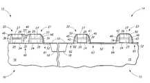
- FIG. 1depicts an exemplary silicon-comprising substrate in the form of bulk monocrystalline silicon material 16 having respective trench isolation regions 18 formed therein.
- semiconductor substrateor “semiconductive substrate” is defined to mean any construction comprising semiconductive material, including, but not limited to, bulk semiconductive materials such as a semiconductive wafer (either alone or in assemblies comprising other materials thereon), and semiconductive material layers (either alone or in assemblies comprising other materials).
- substraterefers to any supporting structure, including, but not limited to, the semiconductive substrates described above. Of course, semiconductor-on-insulator and other substrates are contemplated, and whether existing or yet-to-be developed.
- FIG. 1depicts a pair of device constructions 20 , 21 within first circuitry area 12 , and a pair of device constructions 22 , 23 within second circuitry area 14 .
- suchcomprise gate constructions.
- gate dielectric layers 24depicted as comprising gate dielectric layers 24 , conductively doped polysilicon regions 25 , overlying conductive metal silicide regions 26 and electrically insulative caps 27 .
- conductive regions 25 and 26can be considered as comprising a first pair of spaced adjacent conductive structures 28 and 30 (in this particular example conductive gate electrodes) received over silicon-comprising substrate 16 in at least a first cross-section of the substrate.
- first cross-sectionis depicted as being upon the plane of the page which such are received within first circuitry/memory array area 12 .
- conductive regions 25 and 26can be considered as comprising a second pair of spaced adjacent conductive structures 32 , 34 received over silicon-comprising substrate 16 within second circuitry area 14 at least in a second cross-section of the substrate, for example as depicted by the plane of the page upon which such devices are received within second circuitry area 14 .
- a “cross-section”defines a plane within which lies a shortest straight line that can be drawn between two spaced adjacent conductive structures at issue, for example conductive structures 28 and 30 within first circuitry area 12 in one instance and conductive structures 32 and 34 within second circuitry area 14 in another instance.
- conductive structures 32 and 34 of the second pairare spaced further from one another in the depicted second cross-section (shown by a distance A) than are those spaced adjacent conductive structures 28 and 30 of the first pair in the first cross-section (shown by a distance B).
- the spacing dimension Atypically is at least 1300 Angstroms
- the spacing dimension Btypically ranges between 600 Angstroms and 1000 Angstroms in existing minimum feature technology.
- a typical collective thickness for materials 24 , 25 , 26 and 27is on the order of 2,000 Angstroms.
- an anisotropically etched electrically insulative sidewall spaceris formed over a sidewall of at least one of the conductive structures in at least one of the first and second cross-sections.
- FIG. 1depicts anisotropically etched insulative sidewall spacers 36 , 37 and 38 , 39 associated with conductive structures 28 and 30 , respectively, within first circuitry area 12 in the depicted first cross-section.
- FIG. 1also depicts anisotropically etched electrically insulative sidewall spacers 40 , 41 and 42 , 43 associated with conductive structures 32 and 34 , respectively, within second circuitry area 14 in the depicted second cross-section.
- spacers 37 and 38an be considered as spaced and facing anisotropically etched insulative sidewall spacers provided in the depicted first cross-section in first circuitry area 12 between gate electrodes 28 and 30 of such first pair.
- spacers 41 and 42can be considered as spaced and facing anisotropically etched insulative sidewall spacers provided in the second cross-section in second circuitry area 14 between gate electrodes 32 and 34 of such second pair.
- Facing anisotropically etched sidewall spacers 41 and 42 between the second pair of gate electrodesare spaced further from one another by a distance C in the depicted second cross-section than are those spacers 37 and 38 by a distance D received between first pair of gate electrodes 28 and 30 in the depicted first cross-section in first circuitry area 12 .
- an exemplary dimension Cis at least 1000 Angstroms, with that for dimension D being from 320 Angstroms to 600 Angstroms.
- Exemplary preferred materials for the depicted spacers 36 - 43 and for insulative caps 27include silicon nitride and undoped silicon dioxide. Such spacers and caps might be of the same material or different materials.
- numerals 60 , 61 , 62 , 63 , 64 and 65depict exemplary source/drain regions of the exemplary field effect transistors being fabricated. Such regions might be fully doped, partially doped, or substantially void of conductivity enhancing doping at this point in the process. Further and regardless, such regions might comprise elevated source/drain regions.
- a masking material 46has been deposited between the conductive structures 28 , 30 and 32 , 34 of each of the first and second pairs of such depicted structures, respectively. Further and accordingly in the depicted preferred embodiment, such masking material 46 is also deposited between facing anisotropically etched sidewall spacers 37 , 38 and 41 , 42 received between each of the first and second pairs of gate electrodes 28 , 30 and 32 , 34 , respectively.
- An exemplary deposition thickness range for masking material 46is from 200 Angstroms to 700 Angstroms.
- masking material 46comprises a material that can be selectively etched relative to spacers 36 - 43 , and also preferably relative to insulative caps 27 , and also preferably relative to substrate material 16 .
- a selective etchis where removal of one material relative to another occurs at a removal ratio of at least 2:1.
- Masking material 46might be electrically conductive, electrically insulative or semiconductive.
- exemplary electrically insulative materialsinclude silicon nitride and silicon dioxide.
- Exemplary semiconductive materialsinclude doped semiconductive materials, for example silicon and gallium arsenide.
- Exemplary preferred electrically conductive materialsare conductive metal nitrides, for example tungsten nitride and titanium nitride. Additional exemplary masking materials include amorphous carbon and transparent carbon.
- any such materialscan be deposited by any existing or yet-to-be developed methods, for example preferably by CVD.
- silicon dioxidecan be deposited by bubbling an inert gas through tetraethylorthosilicate.
- Silicon nitridecan be chemical vapor deposited using silane and ammonia.
- Tungsten nitridecan be chemical vapor deposited from WF 6 and NH 3 .
- Titanium nitridecan be chemical vapor deposited from TiCl 4 and NH 3 .
- Amorphous and transparent carbonscan be chemical vapor deposited from C 3 H 6 and otherwise as disclosed in our U.S.
- masking material 46has been removed effective to expose silicon between conductive structures 32 and 34 of such second pair in the depicted second cross-section, but not between conductive structures 28 and 30 of such first pair in the depicted first cross-section. Further and accordingly in the depicted preferred FIG. 3 embodiment, such removing has been effective to expose silicon between facing anisotropically etched sidewall spacers 41 and 42 received between the second pair of conductive gate electrodes in the depicted second cross-section, but not between facing anisotropically etched sidewall spacers 37 and 38 received between the first pair of conductive gate electrodes in the depicted first cross-section. Further, in one preferred technique and as depicted, the removing of the masking material is ineffective to expose any of conductive material 25 , 26 of gate electrodes 28 , 30 and 32 , 34 in the depicted first and second cross-sections, respectively.
- the preferred technique for removing masking material 46comprises chemical etching, and which is substantially selective relative to the material of spacers 36 - 43 .
- an exemplary etching chemistry for etching amorphous or transparent carbon in an anisotropic manner as depictedincludes any suitable fluorine-containing plasma etch, and for an isotropic etch an example would be sulfuric acid and hydrogen peroxide.
- exemplary isotropic etch chemistrieswould include a dilute hydrofluoric acid etch, and a buffered oxide etch using NH 4 F and HF; and for an anisotropic etch would include any suitable fluorine containing plasma etch.
- an exemplary isotropic etch chemistrywould include fluorine, NF 3 , and Ar, and for an anisotropic etch would include either plasma NF 3 and chlorine or plasma HBr and flourine.
- an exemplary isotropic etch chemistrywould include dilute hydrofluoric acid, and for an anisotropic etch would include chlorine.
- the depositing of masking material 46 through the removing of the masking material 46 of FIG. 3occurs without any photolithographic patterning at least within the depicted first and second cross-sections, and even more preferably without any photolithographic patterning anywhere on the substrate from the depositing of the masking material through the removing thereof as depicted in FIG. 3 .
- FIG. 3depicts such removing as leaving secondary sidewall spacers of material 46 over insulative sidewall spacers 39 , 40 , 41 , 42 and 43 .
- a metal 50has been deposited over the substrate.
- Exemplary preferred metalsinclude cobalt, tungsten, titanium, and nickel.
- a preferred deposition thickness for metal 50is from 100 Angstroms to 500 Angstroms.
- substrate 10 with deposited metal 50has been annealed effective to react such metal with silicon of the substrate (i.e., silicon from material 16 ) to form conductive metal silicide 52 , with at least some of such being received between conductive structures 32 and 34 of such second pair of such structures in the depicted second cross-section of second circuitry area 14 , but not between conductive structures 28 and 30 of such first pair of such structures in the depicted first cross-section in first circuitry area 12 .
- Such depositing of metal 50 and the annealing of the substratemight occur simultaneously over at least some period of time during the deposition of metal 50 .
- Such depositing of metal and annealing of the substratemight occur over at least some non-simultaneous periods of time, for example as is essentially depicted by the combination of FIGS. 4 and 5 .
- Exemplary preferred annealing conditions for producing the depicted metal silicide regions 52are in an inert atmosphere from 400° C. to 1020° C. for from 1 second to 5 hours.
- Such processing of metal depositing and substrate annealingis in the depicted preferred embodiment effective to react the metal with silicon of the substrate to form conductive metal silicide 52 at least between facing anisotropically etched sidewall spacers 41 and 42 , but not between facing anisotropically etched sidewall spacers 37 and 38 .
- the metal depositing and substrate annealingare ineffective to form silicide on the conductive material 25 , 26 of the gate electrodes in the first and second cross-sections, for example at least due to spacing of metal 50 therefrom by material of the spacers and the caps 27 .
- unreacted metal material 50has been removed from the substrate, for example by selective chemical etching.
- masking material 46has subsequently been removed from between conductive structures 28 and 30 of such first pair of structures in the depicted first cross-section in first circuitry area 12 .
- such removing after the annealingis of all of masking material 46 in the depicted first cross-section, and even more preferably as shown such removing is of all such masking from the substrate.
- continued etchingutilizing any of the above exemplary chemistries are exemplary removing techniques.
- FIG. 6 depicted masking material 46might remain over the substrate. Regardless, subsequent processing can, of course, occur in the fabrication of integrated circuitry over and/or as part of the substrate. Of course, any of exposed spacers 39 , 40 , 41 , 42 and 43 could be removed as well, although such is not preferred.
- the inventionalso contemplates a method of forming a field effect transistor.
- Such a methodincludes forming a gate electrode of a field effect transistor over a silicon-comprising substrate.
- any of gate electrodes 30 , 32 or 34constitute exemplary such gate electrodes formed over an exemplary silicon-comprising substrate 16 .
- Any of such gate electrodescomprise some sidewall, for example and by way of example only, the depicted sidewalls which happen to be vertically oriented with respect to gate electrodes 30 , 32 or 34 . Other than straight-line and/or vertically oriented sidewalls are also of course contemplated.
- a first electrically insulative anisotropically etched sidewall spaceris formed over the particular sidewall of the particular gate electrode.
- spacers 39 , 40 , 41 , 42 or 43constitute an exemplary such spacer.
- a second anisotropically etched sidewall spaceris formed over and distinct from the first sidewall spacer.
- any of the depicted five remaining spacers 46 (remnant from removing masking material 46 ) in FIG. 3 received laterally over first sidewall spacers 39 , 40 , 41 , 42 and 43are, individually, examples of such a second anisotropically etched spacer which is in some way distinct (meaning discernible is some way from) first spacers 39 , 40 , 41 , 42 or 43 .
- FIG. 1depicted preferred embodiments of FIG.
- such second sidewall spacersare formed “on” (meaning everywhere in this document as being in at least some direct physical contact therewith) the depicted spacers 39 , 40 , 41 , 42 or 43 .
- the second sidewall spaceris comprised of a material which is different from that of the first sidewall spacer.
- the second sidewall spacermight comprise an electrically conductive material, an electrically insulative material, a semiconductive material, or some combination thereof.
- Exemplary preferred materials for the first and second spacersinclude any of those described above for spacers 36 - 43 and material 46 .
- a metalis deposited over the first and second sidewall spacers and over silicon of a source/drain region of the transistor proximate the second sidewall spacer.
- FIG. 4depicts such an embodiment with respect to metal layer 50 .
- Such embodimentalso depicts one preferred implementation where the metal is deposited on the first sidewall spacer, on the second sidewall spacer, and on silicon of the source/drain region.
- the substrateis annealed effective to react the metal with silicon of the substrate to form an electrically conductive metal silicide on the source/drain region which is spaced from the first sidewall spacer.
- any one of regions 52 in FIG. 5depicts such an exemplary electrically conductive metal silicide region. Attributes with respect to such depositing of metal and the annealing thereof, as well as any other attribute(s) with respect to preferred embodiments of forming a field effect transistor, are the same as those described above in connection with the embodiments of methods of forming integrated circuitry, including methods of forming memory circuitry.
- the second sidewall spaceris removed from the substrate after the annealing. For example, and by way of example only, such is depicted in the exemplary embodiment of FIG. 7 .
- second sidewall spacer materialin some instances by way of example only it might be desirable to space the metal silicide contact region of a field effect transistor away from the first or other anisotropically etched spacer(s). For example, if defects might be formed in the silicide, such would be spaced further away from the spacers, and thereby further from the channel region, in such a field effect transistor.
- FIG. 8depicts an alternate embodiment substrate fragment 70 comprising a silicon-comprising substrate 71 .
- An exemplary gate construction 72is formed thereover, and comprises a gate oxide layer 73 , a polysilicon region 74 , a conductive silicide region 75 , and an insulative cap 76 .
- Gate construction 72comprises first electrically insulative anisotropically etched sidewall spacers 80 and 82 , intervening anisotropically etched sidewall spacers 84 and 86 formed thereover, and second anisotropically etched sidewall spacers 88 and 90 formed over intervening anisotropically etched sidewall spacers 84 and 86 , respectively.
- the material of intervening anisotropically etched spacers 84 , 86is different from that of spacers 80 , 82 and 88 , 90 (which of course could be the same or different material relative to one another, per the above).
- Metal layer deposition, annealing and silicide formationcould otherwise occur, by way of example only, as referred to in the previous embodiments above. Further of course, any part or all of individual spacers 80 - 90 could be removed subsequently.
Landscapes
- Engineering & Computer Science (AREA)
- Manufacturing & Machinery (AREA)
- Electrodes Of Semiconductors (AREA)
- Semiconductor Memories (AREA)
- Insulated Gate Type Field-Effect Transistor (AREA)
- Internal Circuitry In Semiconductor Integrated Circuit Devices (AREA)
Abstract
Description
Claims (20)
Priority Applications (4)
| Application Number | Priority Date | Filing Date | Title |
|---|---|---|---|
| US11/003,275US7276433B2 (en) | 2004-12-03 | 2004-12-03 | Methods of forming integrated circuitry, methods of forming memory circuitry, and methods of forming field effect transistors |
| US11/497,598US7439138B2 (en) | 2004-12-03 | 2006-07-31 | Method of forming integrated circuitry |
| US11/704,488US7833892B2 (en) | 2004-12-03 | 2007-02-09 | Method of forming a field effect transistor |
| US11/849,813US7718495B2 (en) | 2004-12-03 | 2007-09-04 | Methods of forming integrated circuitry, methods of forming memory circuitry, and methods of forming field effect transistors |
Applications Claiming Priority (1)
| Application Number | Priority Date | Filing Date | Title |
|---|---|---|---|
| US11/003,275US7276433B2 (en) | 2004-12-03 | 2004-12-03 | Methods of forming integrated circuitry, methods of forming memory circuitry, and methods of forming field effect transistors |
Related Child Applications (3)
| Application Number | Title | Priority Date | Filing Date |
|---|---|---|---|
| US11/497,598ContinuationUS7439138B2 (en) | 2004-12-03 | 2006-07-31 | Method of forming integrated circuitry |
| US11/704,488DivisionUS7833892B2 (en) | 2004-12-03 | 2007-02-09 | Method of forming a field effect transistor |
| US11/849,813DivisionUS7718495B2 (en) | 2004-12-03 | 2007-09-04 | Methods of forming integrated circuitry, methods of forming memory circuitry, and methods of forming field effect transistors |
Publications (2)
| Publication Number | Publication Date |
|---|---|
| US20060121677A1 US20060121677A1 (en) | 2006-06-08 |
| US7276433B2true US7276433B2 (en) | 2007-10-02 |
Family
ID=36574856
Family Applications (4)
| Application Number | Title | Priority Date | Filing Date |
|---|---|---|---|
| US11/003,275Active2025-11-10US7276433B2 (en) | 2004-12-03 | 2004-12-03 | Methods of forming integrated circuitry, methods of forming memory circuitry, and methods of forming field effect transistors |
| US11/497,598Expired - LifetimeUS7439138B2 (en) | 2004-12-03 | 2006-07-31 | Method of forming integrated circuitry |
| US11/704,488Active2027-02-28US7833892B2 (en) | 2004-12-03 | 2007-02-09 | Method of forming a field effect transistor |
| US11/849,813Expired - LifetimeUS7718495B2 (en) | 2004-12-03 | 2007-09-04 | Methods of forming integrated circuitry, methods of forming memory circuitry, and methods of forming field effect transistors |
Family Applications After (3)
| Application Number | Title | Priority Date | Filing Date |
|---|---|---|---|
| US11/497,598Expired - LifetimeUS7439138B2 (en) | 2004-12-03 | 2006-07-31 | Method of forming integrated circuitry |
| US11/704,488Active2027-02-28US7833892B2 (en) | 2004-12-03 | 2007-02-09 | Method of forming a field effect transistor |
| US11/849,813Expired - LifetimeUS7718495B2 (en) | 2004-12-03 | 2007-09-04 | Methods of forming integrated circuitry, methods of forming memory circuitry, and methods of forming field effect transistors |
Country Status (1)
| Country | Link |
|---|---|
| US (4) | US7276433B2 (en) |
Cited By (2)
| Publication number | Priority date | Publication date | Assignee | Title |
|---|---|---|---|---|
| US20060264019A1 (en)* | 2004-12-03 | 2006-11-23 | Parekh Kunal R | Method of forming integrated circuitry |
| US20070212839A1 (en)* | 2006-03-10 | 2007-09-13 | Chao-Hsi Chung | Method for fabricating semiconductor device |
Families Citing this family (23)
| Publication number | Priority date | Publication date | Assignee | Title |
|---|---|---|---|---|
| US7767577B2 (en)* | 2008-02-14 | 2010-08-03 | Chartered Semiconductor Manufacturing, Ltd. | Nested and isolated transistors with reduced impedance difference |
| US9112003B2 (en) | 2011-12-09 | 2015-08-18 | Asm International N.V. | Selective formation of metallic films on metallic surfaces |
| TWI661072B (en) | 2014-02-04 | 2019-06-01 | 荷蘭商Asm Ip控股公司 | Selective deposition of metals, metal oxides, and dielectrics |
| US10047435B2 (en) | 2014-04-16 | 2018-08-14 | Asm Ip Holding B.V. | Dual selective deposition |
| US9490145B2 (en) | 2015-02-23 | 2016-11-08 | Asm Ip Holding B.V. | Removal of surface passivation |
| US10428421B2 (en) | 2015-08-03 | 2019-10-01 | Asm Ip Holding B.V. | Selective deposition on metal or metallic surfaces relative to dielectric surfaces |
| US10695794B2 (en) | 2015-10-09 | 2020-06-30 | Asm Ip Holding B.V. | Vapor phase deposition of organic films |
| US10814349B2 (en) | 2015-10-09 | 2020-10-27 | Asm Ip Holding B.V. | Vapor phase deposition of organic films |
| US10141436B2 (en) | 2016-04-04 | 2018-11-27 | Purdue Research Foundation | Tunnel field effect transistor having anisotropic effective mass channel |
| US11081342B2 (en) | 2016-05-05 | 2021-08-03 | Asm Ip Holding B.V. | Selective deposition using hydrophobic precursors |
| US10453701B2 (en) | 2016-06-01 | 2019-10-22 | Asm Ip Holding B.V. | Deposition of organic films |
| US10373820B2 (en) | 2016-06-01 | 2019-08-06 | Asm Ip Holding B.V. | Deposition of organic films |
| US11430656B2 (en) | 2016-11-29 | 2022-08-30 | Asm Ip Holding B.V. | Deposition of oxide thin films |
| JP7169072B2 (en) | 2017-02-14 | 2022-11-10 | エーエスエム アイピー ホールディング ビー.ブイ. | Selective passivation and selective deposition |
| US10157841B2 (en)* | 2017-04-17 | 2018-12-18 | Micron Technology, Inc. | Construction of integrated circuitry and a method of forming an elevationally-extending conductor laterally between a pair of structures |
| US11501965B2 (en) | 2017-05-05 | 2022-11-15 | Asm Ip Holding B.V. | Plasma enhanced deposition processes for controlled formation of metal oxide thin films |
| KR102684628B1 (en) | 2017-05-16 | 2024-07-15 | 에이에스엠 아이피 홀딩 비.브이. | Selective PEALD of oxides on dielectrics |
| JP2020056104A (en) | 2018-10-02 | 2020-04-09 | エーエスエム アイピー ホールディング ビー.ブイ. | Selective passivation and selective deposition |
| US11965238B2 (en) | 2019-04-12 | 2024-04-23 | Asm Ip Holding B.V. | Selective deposition of metal oxides on metal surfaces |
| US11139163B2 (en) | 2019-10-31 | 2021-10-05 | Asm Ip Holding B.V. | Selective deposition of SiOC thin films |
| TW202140832A (en) | 2020-03-30 | 2021-11-01 | 荷蘭商Asm Ip私人控股有限公司 | Selective deposition of silicon oxide on metal surfaces |
| TWI865747B (en) | 2020-03-30 | 2024-12-11 | 荷蘭商Asm Ip私人控股有限公司 | Simultaneous selective deposition of two different materials on two different surfaces |
| TWI862807B (en) | 2020-03-30 | 2024-11-21 | 荷蘭商Asm Ip私人控股有限公司 | Selective deposition of silicon oxide on dielectric surfaces relative to metal surfaces |
Citations (11)
| Publication number | Priority date | Publication date | Assignee | Title |
|---|---|---|---|---|
| US5247197A (en)* | 1987-11-05 | 1993-09-21 | Fujitsu Limited | Dynamic random access memory device having improved contact hole structures |
| US5495439A (en)* | 1993-09-27 | 1996-02-27 | Mitsubishi Denki Kabushiki Kaisha | Semiconductor memory device having SOI structure and manufacturing method thereof |
| US5777920A (en)* | 1995-12-07 | 1998-07-07 | Mitsubishi Denki Kabushiki Kaisha | Semiconductor memory device and method of manufacturing the same |
| US6180472B1 (en) | 1998-07-28 | 2001-01-30 | Matsushita Electrons Corporation | Method for fabricating semiconductor device |
| US20010005630A1 (en) | 1999-12-03 | 2001-06-28 | Samsung Electronics Co., Ltd. | Method of filling gap by use of high density plasma oxide film and deposition apparatus therefor |
| US6312982B1 (en) | 1998-07-13 | 2001-11-06 | Kabushiki Kaisha Toshiba | Method of fabricating a trench capacitor |
| US20020025644A1 (en)* | 2000-03-03 | 2002-02-28 | Chih-Chen Cho | Structures comprising transistor gates |
| US6383877B1 (en) | 1999-05-20 | 2002-05-07 | Samsung Electronics Co., Ltd. | Method of forming T-shaped isolation layer, method of forming elevated salicide source/drain region using the same, and semiconductor device having T-shaped isolation layer |
| US6707154B2 (en) | 2000-06-30 | 2004-03-16 | Mitsubishi Denki Kabushiki Kaisha | Semiconductor device and production method for the same |
| US20060121677A1 (en)* | 2004-12-03 | 2006-06-08 | Micron Technology, Inc. | Methods of forming integrated circuitry, methods of forming memory circuitry, and methods of forming field effect transistors |
| US20070032011A1 (en)* | 2005-08-02 | 2007-02-08 | Micron Technology, Inc. | Methods of forming memory circuitry |
Family Cites Families (19)
| Publication number | Priority date | Publication date | Assignee | Title |
|---|---|---|---|---|
| US5472887A (en) | 1993-11-09 | 1995-12-05 | Texas Instruments Incorporated | Method of fabricating semiconductor device having high-and low-voltage MOS transistors |
| US5451532A (en) | 1994-03-15 | 1995-09-19 | National Semiconductor Corp. | Process for making self-aligned polysilicon base contact in a bipolar junction transistor |
| US5683930A (en)* | 1995-12-06 | 1997-11-04 | Micron Technology Inc. | SRAM cell employing substantially vertically elongated pull-up resistors and methods of making, and resistor constructions and methods of making |
| US5844276A (en) | 1996-12-06 | 1998-12-01 | Advanced Micro Devices, Inc. | CMOS integrated circuit and method for implanting NMOS transistor areas prior to implanting PMOS transistor areas to optimize the thermal diffusivity thereof |
| US6258671B1 (en)* | 1997-05-13 | 2001-07-10 | Micron Technology, Inc. | Methods of providing spacers over conductive line sidewalls, methods of forming sidewall spacers over etched line sidewalls, and methods of forming conductive lines |
| US5866934A (en) | 1997-06-20 | 1999-02-02 | Advanced Micro Devices, Inc. | Parallel and series-coupled transistors having gate conductors formed on sidewall surfaces of a sacrificial structure |
| KR100257075B1 (en)* | 1998-01-13 | 2000-05-15 | 김영환 | Semiconductor device and method for manufacturing the same |
| TW408354B (en)* | 1999-03-02 | 2000-10-11 | United Microelectronics Corp | Structure of field effect transistor and its manufacture method |
| US6306701B1 (en)* | 1999-04-20 | 2001-10-23 | United Microelectronics Corp. | Self-aligned contact process |
| US6642134B2 (en) | 1999-09-22 | 2003-11-04 | Advanced Micro Devices, Inc. | Semiconductor processing employing a semiconductor spacer |
| JP3464429B2 (en)* | 2000-02-22 | 2003-11-10 | 沖電気工業株式会社 | Structure and manufacturing method of semiconductor electronic device |
| US6329251B1 (en) | 2000-08-10 | 2001-12-11 | Taiwan Semiconductor Manufacturing Company, Ltd | Microelectronic fabrication method employing self-aligned selectively deposited silicon layer |
| US6455362B1 (en)* | 2000-08-22 | 2002-09-24 | Micron Technology, Inc. | Double LDD devices for improved dram refresh |
| US7002223B2 (en)* | 2001-07-27 | 2006-02-21 | Samsung Electronics Co., Ltd. | Semiconductor device having elevated source/drain |
| KR100476887B1 (en)* | 2002-03-28 | 2005-03-17 | 삼성전자주식회사 | Mos transistor with extended silicide layer of source/drain region and method of fabricating thereof |
| US6780708B1 (en)* | 2003-03-05 | 2004-08-24 | Advanced Micro Devices, Inc. | Method of forming core and periphery gates including two critical masking steps to form a hard mask in a core region that includes a critical dimension less than achievable at a resolution limit of lithography |
| DE10335100B4 (en)* | 2003-07-31 | 2008-06-05 | Advanced Micro Devices, Inc., Sunnyvale | A method of fabricating truncated sidewall spacers for a polysilicon line and method of fabricating a field effect transistor |
| JP4521597B2 (en)* | 2004-02-10 | 2010-08-11 | ルネサスエレクトロニクス株式会社 | Semiconductor memory device and manufacturing method thereof |
| US7219857B2 (en)* | 2005-06-20 | 2007-05-22 | The Boeing Company | Controllable refueling drogues and associated systems and methods |
- 2004
- 2004-12-03USUS11/003,275patent/US7276433B2/enactiveActive
- 2006
- 2006-07-31USUS11/497,598patent/US7439138B2/ennot_activeExpired - Lifetime
- 2007
- 2007-02-09USUS11/704,488patent/US7833892B2/enactiveActive
- 2007-09-04USUS11/849,813patent/US7718495B2/ennot_activeExpired - Lifetime
Patent Citations (19)
| Publication number | Priority date | Publication date | Assignee | Title |
|---|---|---|---|---|
| US5405798A (en)* | 1987-11-05 | 1995-04-11 | Fujitsu Limited | Method of producing a dynamic random access memory device having improved contact hole structures |
| US5247197A (en)* | 1987-11-05 | 1993-09-21 | Fujitsu Limited | Dynamic random access memory device having improved contact hole structures |
| US5495439A (en)* | 1993-09-27 | 1996-02-27 | Mitsubishi Denki Kabushiki Kaisha | Semiconductor memory device having SOI structure and manufacturing method thereof |
| US5888854A (en)* | 1993-09-27 | 1999-03-30 | Mitsubishi Denki Kabushiki Kaisha | Method of manufacturing a DRAM having an SOI structure |
| US5777920A (en)* | 1995-12-07 | 1998-07-07 | Mitsubishi Denki Kabushiki Kaisha | Semiconductor memory device and method of manufacturing the same |
| US6312982B1 (en) | 1998-07-13 | 2001-11-06 | Kabushiki Kaisha Toshiba | Method of fabricating a trench capacitor |
| US6492665B1 (en) | 1998-07-28 | 2002-12-10 | Matsushita Electric Industrial Co., Ltd. | Semiconductor device |
| US6180472B1 (en) | 1998-07-28 | 2001-01-30 | Matsushita Electrons Corporation | Method for fabricating semiconductor device |
| US6383877B1 (en) | 1999-05-20 | 2002-05-07 | Samsung Electronics Co., Ltd. | Method of forming T-shaped isolation layer, method of forming elevated salicide source/drain region using the same, and semiconductor device having T-shaped isolation layer |
| US20010005630A1 (en) | 1999-12-03 | 2001-06-28 | Samsung Electronics Co., Ltd. | Method of filling gap by use of high density plasma oxide film and deposition apparatus therefor |
| US20020025644A1 (en)* | 2000-03-03 | 2002-02-28 | Chih-Chen Cho | Structures comprising transistor gates |
| US6420250B1 (en)* | 2000-03-03 | 2002-07-16 | Micron Technology, Inc. | Methods of forming portions of transistor structures, methods of forming array peripheral circuitry, and structures comprising transistor gates |
| US6501114B2 (en)* | 2000-03-03 | 2002-12-31 | Micron Technology, Inc. | Structures comprising transistor gates |
| US20030073277A1 (en)* | 2000-03-03 | 2003-04-17 | Chih-Chen Cho | Structures comprising transistor gates |
| US6707154B2 (en) | 2000-06-30 | 2004-03-16 | Mitsubishi Denki Kabushiki Kaisha | Semiconductor device and production method for the same |
| US20060121677A1 (en)* | 2004-12-03 | 2006-06-08 | Micron Technology, Inc. | Methods of forming integrated circuitry, methods of forming memory circuitry, and methods of forming field effect transistors |
| US20060264019A1 (en)* | 2004-12-03 | 2006-11-23 | Parekh Kunal R | Method of forming integrated circuitry |
| US20070141821A1 (en)* | 2004-12-03 | 2007-06-21 | Parekh Kunal R | Method of forming integrated circuitry, methods of forming memory circuitry, and methods of forming field effect transistors |
| US20070032011A1 (en)* | 2005-08-02 | 2007-02-08 | Micron Technology, Inc. | Methods of forming memory circuitry |
Non-Patent Citations (1)
| Title |
|---|
| Cataldo, 'Embedded DRAM gets pure-logic performance', [online]. Sep. 11, 2000, EETimes, pp. 1-3, [retrieved on Sep. 9, 2004]. Retrieved from the Internet: <URL: http://www.eetimes.com/article/printableArticle.jhtml;jsessionid=IX1A0LUTNJ4PKQSN...>. |
Cited By (7)
| Publication number | Priority date | Publication date | Assignee | Title |
|---|---|---|---|---|
| US20060264019A1 (en)* | 2004-12-03 | 2006-11-23 | Parekh Kunal R | Method of forming integrated circuitry |
| US20070141821A1 (en)* | 2004-12-03 | 2007-06-21 | Parekh Kunal R | Method of forming integrated circuitry, methods of forming memory circuitry, and methods of forming field effect transistors |
| US20070298570A1 (en)* | 2004-12-03 | 2007-12-27 | Parekh Kunal R | Methods of Forming Integrated Circuitry, Methods of Forming Memory Circuitry, and Methods of Forming Field Effect Transistors |
| US7439138B2 (en)* | 2004-12-03 | 2008-10-21 | Micron Technology, Inc. | Method of forming integrated circuitry |
| US7718495B2 (en)* | 2004-12-03 | 2010-05-18 | Micron Technology, Inc. | Methods of forming integrated circuitry, methods of forming memory circuitry, and methods of forming field effect transistors |
| US7833892B2 (en) | 2004-12-03 | 2010-11-16 | Micron Technology, Inc. | Method of forming a field effect transistor |
| US20070212839A1 (en)* | 2006-03-10 | 2007-09-13 | Chao-Hsi Chung | Method for fabricating semiconductor device |
Also Published As
| Publication number | Publication date |
|---|---|
| US20070141821A1 (en) | 2007-06-21 |
| US20070298570A1 (en) | 2007-12-27 |
| US7718495B2 (en) | 2010-05-18 |
| US7833892B2 (en) | 2010-11-16 |
| US7439138B2 (en) | 2008-10-21 |
| US20060264019A1 (en) | 2006-11-23 |
| US20060121677A1 (en) | 2006-06-08 |
Similar Documents
| Publication | Publication Date | Title |
|---|---|---|
| US7718495B2 (en) | Methods of forming integrated circuitry, methods of forming memory circuitry, and methods of forming field effect transistors | |
| US7557396B2 (en) | Semiconductor device and method of manufacturing semiconductor device | |
| US8557662B2 (en) | Method for fabricating side contact in semiconductor device using double trench process | |
| US7419865B2 (en) | Methods of forming memory circuitry | |
| JP2007335891A (en) | Semiconductor device | |
| US9595527B2 (en) | Coaxial carbon nanotube capacitor for eDRAM | |
| US20020098633A1 (en) | Use of selective ozone TEOS oxide to create variable thickness layers and spacers | |
| US7320919B2 (en) | Method for fabricating semiconductor device with metal-polycide gate and recessed channel | |
| US5457065A (en) | method of manufacturing a new DRAM capacitor structure having increased capacitance | |
| US20040126963A1 (en) | Capacitor fabrication method | |
| CN115274560B (en) | Method for manufacturing semiconductor structure and semiconductor structure | |
| WO2022016985A1 (en) | Buried gate electrode and manufacturing method therefor | |
| US6746913B2 (en) | Method of manufacturing semiconductor integrated circuit device comprising a memory cell and a capacitor | |
| US7026207B2 (en) | Method of filling bit line contact via | |
| KR101255764B1 (en) | Method of manufacturing a capacitor in a semiconductor device | |
| US7652323B2 (en) | Semiconductor device having step gates and method of manufacturing the same | |
| KR20040061279A (en) | A method for forming a semiconductor device | |
| KR20000043217A (en) | Fabrication method of transistor of semiconductor device | |
| KR19990057889A (en) | Method for forming conductive layer of polyside structure | |
| JP2008227037A (en) | Semiconductor device and manufacturing method thereof |
Legal Events
| Date | Code | Title | Description |
|---|---|---|---|
| AS | Assignment | Owner name:MICRON TECHNOLOGY, INC., IDAHO Free format text:ASSIGNMENT OF ASSIGNORS INTEREST;ASSIGNORS:PAREKH, KUNAL R.;ZAHURAK, JOHN K.;REEL/FRAME:016064/0004 Effective date:20041202 | |
| FEPP | Fee payment procedure | Free format text:PAYOR NUMBER ASSIGNED (ORIGINAL EVENT CODE: ASPN); ENTITY STATUS OF PATENT OWNER: LARGE ENTITY | |
| STCF | Information on status: patent grant | Free format text:PATENTED CASE | |
| CC | Certificate of correction | ||
| FPAY | Fee payment | Year of fee payment:4 | |
| FPAY | Fee payment | Year of fee payment:8 | |
| AS | Assignment | Owner name:U.S. BANK NATIONAL ASSOCIATION, AS COLLATERAL AGENT, CALIFORNIA Free format text:SECURITY INTEREST;ASSIGNOR:MICRON TECHNOLOGY, INC.;REEL/FRAME:038669/0001 Effective date:20160426 Owner name:U.S. BANK NATIONAL ASSOCIATION, AS COLLATERAL AGEN Free format text:SECURITY INTEREST;ASSIGNOR:MICRON TECHNOLOGY, INC.;REEL/FRAME:038669/0001 Effective date:20160426 | |
| AS | Assignment | Owner name:MORGAN STANLEY SENIOR FUNDING, INC., AS COLLATERAL AGENT, MARYLAND Free format text:PATENT SECURITY AGREEMENT;ASSIGNOR:MICRON TECHNOLOGY, INC.;REEL/FRAME:038954/0001 Effective date:20160426 Owner name:MORGAN STANLEY SENIOR FUNDING, INC., AS COLLATERAL Free format text:PATENT SECURITY AGREEMENT;ASSIGNOR:MICRON TECHNOLOGY, INC.;REEL/FRAME:038954/0001 Effective date:20160426 | |
| AS | Assignment | Owner name:U.S. BANK NATIONAL ASSOCIATION, AS COLLATERAL AGENT, CALIFORNIA Free format text:CORRECTIVE ASSIGNMENT TO CORRECT THE REPLACE ERRONEOUSLY FILED PATENT #7358718 WITH THE CORRECT PATENT #7358178 PREVIOUSLY RECORDED ON REEL 038669 FRAME 0001. ASSIGNOR(S) HEREBY CONFIRMS THE SECURITY INTEREST;ASSIGNOR:MICRON TECHNOLOGY, INC.;REEL/FRAME:043079/0001 Effective date:20160426 Owner name:U.S. BANK NATIONAL ASSOCIATION, AS COLLATERAL AGEN Free format text:CORRECTIVE ASSIGNMENT TO CORRECT THE REPLACE ERRONEOUSLY FILED PATENT #7358718 WITH THE CORRECT PATENT #7358178 PREVIOUSLY RECORDED ON REEL 038669 FRAME 0001. ASSIGNOR(S) HEREBY CONFIRMS THE SECURITY INTEREST;ASSIGNOR:MICRON TECHNOLOGY, INC.;REEL/FRAME:043079/0001 Effective date:20160426 | |
| AS | Assignment | Owner name:JPMORGAN CHASE BANK, N.A., AS COLLATERAL AGENT, ILLINOIS Free format text:SECURITY INTEREST;ASSIGNORS:MICRON TECHNOLOGY, INC.;MICRON SEMICONDUCTOR PRODUCTS, INC.;REEL/FRAME:047540/0001 Effective date:20180703 Owner name:JPMORGAN CHASE BANK, N.A., AS COLLATERAL AGENT, IL Free format text:SECURITY INTEREST;ASSIGNORS:MICRON TECHNOLOGY, INC.;MICRON SEMICONDUCTOR PRODUCTS, INC.;REEL/FRAME:047540/0001 Effective date:20180703 | |
| AS | Assignment | Owner name:MICRON TECHNOLOGY, INC., IDAHO Free format text:RELEASE BY SECURED PARTY;ASSIGNOR:U.S. BANK NATIONAL ASSOCIATION, AS COLLATERAL AGENT;REEL/FRAME:047243/0001 Effective date:20180629 | |
| MAFP | Maintenance fee payment | Free format text:PAYMENT OF MAINTENANCE FEE, 12TH YEAR, LARGE ENTITY (ORIGINAL EVENT CODE: M1553); ENTITY STATUS OF PATENT OWNER: LARGE ENTITY Year of fee payment:12 | |
| AS | Assignment | Owner name:MICRON TECHNOLOGY, INC., IDAHO Free format text:RELEASE BY SECURED PARTY;ASSIGNOR:MORGAN STANLEY SENIOR FUNDING, INC., AS COLLATERAL AGENT;REEL/FRAME:050937/0001 Effective date:20190731 | |
| AS | Assignment | Owner name:MICRON TECHNOLOGY, INC., IDAHO Free format text:RELEASE BY SECURED PARTY;ASSIGNOR:JPMORGAN CHASE BANK, N.A., AS COLLATERAL AGENT;REEL/FRAME:051028/0001 Effective date:20190731 Owner name:MICRON SEMICONDUCTOR PRODUCTS, INC., IDAHO Free format text:RELEASE BY SECURED PARTY;ASSIGNOR:JPMORGAN CHASE BANK, N.A., AS COLLATERAL AGENT;REEL/FRAME:051028/0001 Effective date:20190731 |