US7276063B2 - Instrument for electrosurgical tissue treatment - Google Patents
Instrument for electrosurgical tissue treatmentDownload PDFInfo
- Publication number
- US7276063B2 US7276063B2US10/661,118US66111803AUS7276063B2US 7276063 B2US7276063 B2US 7276063B2US 66111803 AUS66111803 AUS 66111803AUS 7276063 B2US7276063 B2US 7276063B2
- Authority
- US
- United States
- Prior art keywords
- tissue
- electrode
- instrument
- active
- active electrode
- Prior art date
- Legal status (The legal status is an assumption and is not a legal conclusion. Google has not performed a legal analysis and makes no representation as to the accuracy of the status listed.)
- Expired - Lifetime, expires
Links
- 238000011282treatmentMethods0.000titleclaimsdescription57
- 239000012530fluidSubstances0.000claimsabstractdescription216
- 239000000463materialSubstances0.000claimsdescription32
- 239000000919ceramicSubstances0.000claimsdescription15
- 230000000694effectsEffects0.000claimsdescription15
- 238000013022ventingMethods0.000claimsdescription4
- 239000011800void materialSubstances0.000claims2
- 239000000523sampleSubstances0.000abstractdescription148
- 238000000034methodMethods0.000abstractdescription123
- 238000002679ablationMethods0.000abstractdescription91
- 230000008569processEffects0.000abstractdescription24
- 238000010494dissociation reactionMethods0.000abstractdescription19
- 230000005593dissociationsEffects0.000abstractdescription19
- 230000005684electric fieldEffects0.000abstractdescription17
- 239000003574free electronSubstances0.000abstractdescription4
- 210000001519tissueAnatomy0.000description367
- 210000002381plasmaAnatomy0.000description91
- BASFCYQUMIYNBI-UHFFFAOYSA-NplatinumChemical compound[Pt]BASFCYQUMIYNBI-UHFFFAOYSA-N0.000description86
- FAPWRFPIFSIZLT-UHFFFAOYSA-MSodium chlorideChemical compound[Na+].[Cl-]FAPWRFPIFSIZLT-UHFFFAOYSA-M0.000description62
- 239000010410layerSubstances0.000description49
- 150000002500ionsChemical class0.000description45
- 229910052697platinumInorganic materials0.000description42
- 239000011780sodium chlorideSubstances0.000description29
- 239000012634fragmentSubstances0.000description24
- 238000010438heat treatmentMethods0.000description24
- 125000006850spacer groupChemical group0.000description24
- 238000005345coagulationMethods0.000description21
- 230000015271coagulationEffects0.000description21
- 239000007789gasSubstances0.000description21
- 239000007788liquidSubstances0.000description20
- 230000000670limiting effectEffects0.000description19
- 239000002245particleSubstances0.000description18
- 230000017074necrotic cell deathEffects0.000description16
- 210000005036nerveAnatomy0.000description16
- 210000002683footAnatomy0.000description15
- 230000001965increasing effectEffects0.000description15
- 238000001356surgical procedureMethods0.000description15
- 206010028980NeoplasmDiseases0.000description14
- 230000006378damageEffects0.000description14
- 229910052751metalInorganic materials0.000description14
- 230000008016vaporizationEffects0.000description14
- 229910045601alloyInorganic materials0.000description13
- 239000000956alloySubstances0.000description13
- 230000006870functionEffects0.000description13
- 239000002184metalSubstances0.000description13
- 238000009834vaporizationMethods0.000description12
- 210000004369bloodAnatomy0.000description11
- 239000008280bloodSubstances0.000description11
- 238000005520cutting processMethods0.000description11
- 239000011521glassSubstances0.000description11
- 210000003128headAnatomy0.000description11
- 230000008901benefitEffects0.000description10
- 210000004027cellAnatomy0.000description10
- 230000007246mechanismEffects0.000description10
- 239000000243solutionSubstances0.000description10
- 210000000988bone and boneAnatomy0.000description9
- 230000008878couplingEffects0.000description9
- 238000010168coupling processMethods0.000description9
- 238000005859coupling reactionMethods0.000description9
- 239000000047productSubstances0.000description9
- 230000003685thermal hair damageEffects0.000description9
- 238000009835boilingMethods0.000description8
- 229910052741iridiumInorganic materials0.000description8
- 239000011159matrix materialSubstances0.000description8
- HWLDNSXPUQTBOD-UHFFFAOYSA-Nplatinum-iridium alloyChemical class[Ir].[Pt]HWLDNSXPUQTBOD-UHFFFAOYSA-N0.000description8
- RTAQQCXQSZGOHL-UHFFFAOYSA-NTitaniumChemical compound[Ti]RTAQQCXQSZGOHL-UHFFFAOYSA-N0.000description7
- 239000000853adhesiveSubstances0.000description7
- 230000001070adhesive effectEffects0.000description7
- 210000000577adipose tissueAnatomy0.000description7
- 238000004519manufacturing processMethods0.000description7
- 210000003491skinAnatomy0.000description7
- 229910052721tungstenInorganic materials0.000description7
- 239000010937tungstenSubstances0.000description7
- PXHVJJICTQNCMI-UHFFFAOYSA-NNickelChemical compound[Ni]PXHVJJICTQNCMI-UHFFFAOYSA-N0.000description6
- 125000004429atomChemical group0.000description6
- 238000000576coating methodMethods0.000description6
- 239000004020conductorSubstances0.000description6
- 230000007423decreaseEffects0.000description6
- 230000004907fluxEffects0.000description6
- 230000009467reductionEffects0.000description6
- 238000002271resectionMethods0.000description6
- 210000005222synovial tissueAnatomy0.000description6
- 239000010936titaniumSubstances0.000description6
- 229910052719titaniumInorganic materials0.000description6
- WFKWXMTUELFFGS-UHFFFAOYSA-NtungstenChemical compound[W]WFKWXMTUELFFGS-UHFFFAOYSA-N0.000description6
- CURLTUGMZLYLDI-UHFFFAOYSA-NCarbon dioxideChemical compoundO=C=OCURLTUGMZLYLDI-UHFFFAOYSA-N0.000description5
- RYGMFSIKBFXOCR-UHFFFAOYSA-NCopperChemical compound[Cu]RYGMFSIKBFXOCR-UHFFFAOYSA-N0.000description5
- 230000008602contractionEffects0.000description5
- 239000010949copperSubstances0.000description5
- 229910052802copperInorganic materials0.000description5
- 238000013461designMethods0.000description5
- 230000000977initiatory effectEffects0.000description5
- 201000010260leiomyomaDiseases0.000description5
- 239000000203mixtureSubstances0.000description5
- 210000000214mouthAnatomy0.000description5
- 210000004126nerve fiberAnatomy0.000description5
- 230000037361pathwayEffects0.000description5
- 239000004033plasticSubstances0.000description5
- 229920003023plasticPolymers0.000description5
- 230000002829reductive effectEffects0.000description5
- 229910001220stainless steelInorganic materials0.000description5
- 239000010935stainless steelSubstances0.000description5
- 230000000451tissue damageEffects0.000description5
- 231100000827tissue damageToxicity0.000description5
- XKRFYHLGVUSROY-UHFFFAOYSA-NArgonChemical compound[Ar]XKRFYHLGVUSROY-UHFFFAOYSA-N0.000description4
- IJGRMHOSHXDMSA-UHFFFAOYSA-NAtomic nitrogenChemical compoundN#NIJGRMHOSHXDMSA-UHFFFAOYSA-N0.000description4
- 102000008186CollagenHuman genes0.000description4
- 108010035532CollagenProteins0.000description4
- ZOKXTWBITQBERF-UHFFFAOYSA-NMolybdenumChemical compound[Mo]ZOKXTWBITQBERF-UHFFFAOYSA-N0.000description4
- 238000009825accumulationMethods0.000description4
- PNEYBMLMFCGWSK-UHFFFAOYSA-Naluminium oxideInorganic materials[O-2].[O-2].[O-2].[Al+3].[Al+3]PNEYBMLMFCGWSK-UHFFFAOYSA-N0.000description4
- 230000015556catabolic processEffects0.000description4
- 229920001436collagenPolymers0.000description4
- 238000002316cosmetic surgeryMethods0.000description4
- 150000002739metalsChemical class0.000description4
- VNWKTOKETHGBQD-UHFFFAOYSA-NmethaneChemical compoundCVNWKTOKETHGBQD-UHFFFAOYSA-N0.000description4
- 229910052750molybdenumInorganic materials0.000description4
- 239000011733molybdenumSubstances0.000description4
- 210000000578peripheral nerveAnatomy0.000description4
- -1polytetrafluoroethylenePolymers0.000description4
- 241000894007speciesSpecies0.000description4
- 210000001944turbinateAnatomy0.000description4
- DGAQECJNVWCQMB-PUAWFVPOSA-MIlexoside XXIXChemical compoundC[C@@H]1CC[C@@]2(CC[C@@]3(C(=CC[C@H]4[C@]3(CC[C@@H]5[C@@]4(CC[C@@H](C5(C)C)OS(=O)(=O)[O-])C)C)[C@@H]2[C@]1(C)O)C)C(=O)O[C@H]6[C@@H]([C@H]([C@@H]([C@H](O6)CO)O)O)O.[Na+]DGAQECJNVWCQMB-PUAWFVPOSA-M0.000description3
- OKKJLVBELUTLKV-UHFFFAOYSA-NMethanolChemical compoundOCOKKJLVBELUTLKV-UHFFFAOYSA-N0.000description3
- ZLMJMSJWJFRBEC-UHFFFAOYSA-NPotassiumChemical compound[K]ZLMJMSJWJFRBEC-UHFFFAOYSA-N0.000description3
- 229910052581Si3N4Inorganic materials0.000description3
- 238000003491arrayMethods0.000description3
- 210000001188articular cartilageAnatomy0.000description3
- QVGXLLKOCUKJST-UHFFFAOYSA-Natomic oxygenChemical compound[O]QVGXLLKOCUKJST-UHFFFAOYSA-N0.000description3
- 239000003990capacitorSubstances0.000description3
- 229910002092carbon dioxideInorganic materials0.000description3
- 230000000747cardiac effectEffects0.000description3
- 238000007675cardiac surgeryMethods0.000description3
- 230000001413cellular effectEffects0.000description3
- 230000008859changeEffects0.000description3
- 239000011248coating agentSubstances0.000description3
- 239000007772electrode materialSubstances0.000description3
- 230000023597hemostasisEffects0.000description3
- 239000001257hydrogenSubstances0.000description3
- 229910052739hydrogenInorganic materials0.000description3
- GKOZUEZYRPOHIO-UHFFFAOYSA-Niridium atomChemical compound[Ir]GKOZUEZYRPOHIO-UHFFFAOYSA-N0.000description3
- 210000003097mucusAnatomy0.000description3
- 210000003928nasal cavityAnatomy0.000description3
- 229910052759nickelInorganic materials0.000description3
- 210000001331noseAnatomy0.000description3
- 230000003647oxidationEffects0.000description3
- 238000007254oxidation reactionMethods0.000description3
- 239000001301oxygenSubstances0.000description3
- 229910052760oxygenInorganic materials0.000description3
- 210000003800pharynxAnatomy0.000description3
- 229920000642polymerPolymers0.000description3
- 229920001296polysiloxanePolymers0.000description3
- 229920001343polytetrafluoroethylenePolymers0.000description3
- 239000004810polytetrafluoroethyleneSubstances0.000description3
- 239000011591potassiumSubstances0.000description3
- 229910052700potassiumInorganic materials0.000description3
- 238000007789sealingMethods0.000description3
- 239000003566sealing materialSubstances0.000description3
- HQVNEWCFYHHQES-UHFFFAOYSA-Nsilicon nitrideChemical compoundN12[Si]34N5[Si]62N3[Si]51N64HQVNEWCFYHHQES-UHFFFAOYSA-N0.000description3
- 239000011734sodiumSubstances0.000description3
- 229910052708sodiumInorganic materials0.000description3
- 239000002344surface layerSubstances0.000description3
- 238000012546transferMethods0.000description3
- XLYOFNOQVPJJNP-UHFFFAOYSA-NwaterSubstancesOXLYOFNOQVPJJNP-UHFFFAOYSA-N0.000description3
- OYPRJOBELJOOCE-UHFFFAOYSA-NCalciumChemical compound[Ca]OYPRJOBELJOOCE-UHFFFAOYSA-N0.000description2
- OKTJSMMVPCPJKN-UHFFFAOYSA-NCarbonChemical compound[C]OKTJSMMVPCPJKN-UHFFFAOYSA-N0.000description2
- ZAMOUSCENKQFHK-UHFFFAOYSA-NChlorine atomChemical compound[Cl]ZAMOUSCENKQFHK-UHFFFAOYSA-N0.000description2
- 239000004593EpoxySubstances0.000description2
- PXGOKWXKJXAPGV-UHFFFAOYSA-NFluorineChemical compoundFFPXGOKWXKJXAPGV-UHFFFAOYSA-N0.000description2
- UFHFLCQGNIYNRP-UHFFFAOYSA-NHydrogenChemical compound[H][H]UFHFLCQGNIYNRP-UHFFFAOYSA-N0.000description2
- FYYHWMGAXLPEAU-UHFFFAOYSA-NMagnesiumChemical compound[Mg]FYYHWMGAXLPEAU-UHFFFAOYSA-N0.000description2
- 229910000566Platinum-iridium alloyInorganic materials0.000description2
- 208000037062PolypsDiseases0.000description2
- WCUXLLCKKVVCTQ-UHFFFAOYSA-MPotassium chlorideChemical compound[Cl-].[K+]WCUXLLCKKVVCTQ-UHFFFAOYSA-M0.000description2
- 229910001260Pt alloyInorganic materials0.000description2
- 206010046798Uterine leiomyomaDiseases0.000description2
- MCMNRKCIXSYSNV-UHFFFAOYSA-NZirconium dioxideChemical compoundO=[Zr]=OMCMNRKCIXSYSNV-UHFFFAOYSA-N0.000description2
- 238000011256aggressive treatmentMethods0.000description2
- WYTGDNHDOZPMIW-RCBQFDQVSA-NalstonineNatural productsC1=CC2=C3C=CC=CC3=NC2=C2N1C[C@H]1[C@H](C)OC=C(C(=O)OC)[C@H]1C2WYTGDNHDOZPMIW-RCBQFDQVSA-N0.000description2
- 239000007864aqueous solutionSubstances0.000description2
- 229910052786argonInorganic materials0.000description2
- 230000015572biosynthetic processEffects0.000description2
- 210000004556brainAnatomy0.000description2
- 239000006227byproductSubstances0.000description2
- 239000011575calciumSubstances0.000description2
- 229910052791calciumInorganic materials0.000description2
- 229910052799carbonInorganic materials0.000description2
- 239000001569carbon dioxideSubstances0.000description2
- 210000000845cartilageAnatomy0.000description2
- 239000000460chlorineSubstances0.000description2
- 229910052801chlorineInorganic materials0.000description2
- 239000003086colorantSubstances0.000description2
- 150000001875compoundsChemical class0.000description2
- 210000002808connective tissueAnatomy0.000description2
- 210000004351coronary vesselAnatomy0.000description2
- 239000002537cosmeticSubstances0.000description2
- 230000003247decreasing effectEffects0.000description2
- 210000004177elastic tissueAnatomy0.000description2
- 229920001971elastomerPolymers0.000description2
- 239000000806elastomerSubstances0.000description2
- 239000012777electrically insulating materialSubstances0.000description2
- 239000003792electrolyteSubstances0.000description2
- 238000002674endoscopic surgeryMethods0.000description2
- 230000001815facial effectEffects0.000description2
- 239000000835fiberSubstances0.000description2
- 210000000968fibrocartilageAnatomy0.000description2
- 229910052731fluorineInorganic materials0.000description2
- 239000011737fluorineSubstances0.000description2
- 229920002313fluoropolymerPolymers0.000description2
- 230000005484gravityEffects0.000description2
- 229930195733hydrocarbonNatural products0.000description2
- 150000002430hydrocarbonsChemical class0.000description2
- 230000001939inductive effectEffects0.000description2
- 238000002684laminectomyMethods0.000description2
- 230000003902lesionEffects0.000description2
- 239000011777magnesiumSubstances0.000description2
- 229910052749magnesiumInorganic materials0.000description2
- 238000002844meltingMethods0.000description2
- 230000008018meltingEffects0.000description2
- 229910052757nitrogenInorganic materials0.000description2
- 230000000737periodic effectEffects0.000description2
- 238000006303photolysis reactionMethods0.000description2
- 210000002307prostateAnatomy0.000description2
- 231100000241scarToxicity0.000description2
- 229910001415sodium ionInorganic materials0.000description2
- 239000007787solidSubstances0.000description2
- 238000000859sublimationMethods0.000description2
- 230000008022sublimationEffects0.000description2
- 239000000126substanceSubstances0.000description2
- 210000002435tendonAnatomy0.000description2
- 210000004291uterusAnatomy0.000description2
- 0*C[C@](**(CCN)*1)C1=CC*Chemical compound*C[C@](**(CCN)*1)C1=CC*0.000description1
- 241000321096AdenoidesSpecies0.000description1
- 241001631457CannulaSpecies0.000description1
- 239000004215Carbon black (E152)Substances0.000description1
- 208000032544CicatrixDiseases0.000description1
- 229910052691ErbiumInorganic materials0.000description1
- 241000587161GomphocarpusSpecies0.000description1
- 229910052689HolmiumInorganic materials0.000description1
- XQFRJNBWHJMXHO-RRKCRQDMSA-NIDURChemical compoundC1[C@H](O)[C@@H](CO)O[C@H]1N1C(=O)NC(=O)C(I)=C1XQFRJNBWHJMXHO-RRKCRQDMSA-N0.000description1
- 208000003618Intervertebral Disc DisplacementDiseases0.000description1
- 208000031264Nerve root compressionDiseases0.000description1
- 239000004677NylonSubstances0.000description1
- 241001631646PapillomaviridaeSpecies0.000description1
- 208000031481Pathologic ConstrictionDiseases0.000description1
- 208000012641Pigmentation diseaseDiseases0.000description1
- 239000004952PolyamideSubstances0.000description1
- 239000004642PolyimideSubstances0.000description1
- 206010036940Prostatic adenomaDiseases0.000description1
- 206010037779RadiculopathyDiseases0.000description1
- XUIMIQQOPSSXEZ-UHFFFAOYSA-NSiliconChemical compound[Si]XUIMIQQOPSSXEZ-UHFFFAOYSA-N0.000description1
- 206010041235SnoringDiseases0.000description1
- NRTOMJZYCJJWKI-UHFFFAOYSA-NTitanium nitrideChemical compound[Ti]#NNRTOMJZYCJJWKI-UHFFFAOYSA-N0.000description1
- 208000007097Urinary Bladder NeoplasmsDiseases0.000description1
- 208000014070Vestibular schwannomaDiseases0.000description1
- 206010047675Vocal cord polypDiseases0.000description1
- 230000002159abnormal effectEffects0.000description1
- 238000010521absorption reactionMethods0.000description1
- 208000004064acoustic neuromaDiseases0.000description1
- 230000003213activating effectEffects0.000description1
- 230000006978adaptationEffects0.000description1
- 210000002534adenoidAnatomy0.000description1
- 229910052782aluminiumInorganic materials0.000description1
- XAGFODPZIPBFFR-UHFFFAOYSA-NaluminiumChemical compound[Al]XAGFODPZIPBFFR-UHFFFAOYSA-N0.000description1
- 210000003423ankleAnatomy0.000description1
- 238000013459approachMethods0.000description1
- 230000001580bacterial effectEffects0.000description1
- 229910052788bariumInorganic materials0.000description1
- DSAJWYNOEDNPEQ-UHFFFAOYSA-Nbarium atomChemical compound[Ba]DSAJWYNOEDNPEQ-UHFFFAOYSA-N0.000description1
- 239000000560biocompatible materialSubstances0.000description1
- 230000000740bleeding effectEffects0.000description1
- 210000004204blood vesselAnatomy0.000description1
- 238000003763carbonizationMethods0.000description1
- 230000010261cell growthEffects0.000description1
- 238000006243chemical reactionMethods0.000description1
- 238000010276constructionMethods0.000description1
- 238000007796conventional methodMethods0.000description1
- 238000001816coolingMethods0.000description1
- 230000007797corrosionEffects0.000description1
- 238000005260corrosionMethods0.000description1
- 210000003792cranial nerveAnatomy0.000description1
- 230000001186cumulative effectEffects0.000description1
- 230000000991decompressive effectEffects0.000description1
- 230000007812deficiencyEffects0.000description1
- 230000006735deficitEffects0.000description1
- 210000004207dermisAnatomy0.000description1
- 238000002845discolorationMethods0.000description1
- 201000010099diseaseDiseases0.000description1
- 208000037265diseases, disorders, signs and symptomsDiseases0.000description1
- 230000002500effect on skinEffects0.000description1
- 210000001513elbowAnatomy0.000description1
- 238000010891electric arcMethods0.000description1
- 238000010292electrical insulationMethods0.000description1
- 238000011846endoscopic investigationMethods0.000description1
- 238000013129endoscopic sinus surgeryMethods0.000description1
- 210000002615epidermisAnatomy0.000description1
- UYAHIZSMUZPPFV-UHFFFAOYSA-NerbiumChemical compound[Er]UYAHIZSMUZPPFV-UHFFFAOYSA-N0.000description1
- 210000003238esophagusAnatomy0.000description1
- 229920000840ethylene tetrafluoroethylene copolymerPolymers0.000description1
- 238000001704evaporationMethods0.000description1
- 230000008020evaporationEffects0.000description1
- 230000005284excitationEffects0.000description1
- 210000000256facial nerveAnatomy0.000description1
- 238000001914filtrationMethods0.000description1
- 239000004811fluoropolymerSubstances0.000description1
- 238000011010flushing procedureMethods0.000description1
- 230000004927fusionEffects0.000description1
- 238000002682general surgeryMethods0.000description1
- 239000002241glass-ceramicSubstances0.000description1
- PCHJSUWPFVWCPO-UHFFFAOYSA-NgoldChemical compound[Au]PCHJSUWPFVWCPO-UHFFFAOYSA-N0.000description1
- 229910052737goldInorganic materials0.000description1
- 239000010931goldSubstances0.000description1
- 208000006454hepatitisDiseases0.000description1
- 231100000283hepatitisToxicity0.000description1
- 210000001624hipAnatomy0.000description1
- KJZYNXUDTRRSPN-UHFFFAOYSA-Nholmium atomChemical compound[Ho]KJZYNXUDTRRSPN-UHFFFAOYSA-N0.000description1
- 150000002431hydrogenChemical class0.000description1
- 230000001969hypertrophic effectEffects0.000description1
- 230000001976improved effectEffects0.000description1
- 238000011065in-situ storageMethods0.000description1
- 230000002401inhibitory effectEffects0.000description1
- 238000013383initial experimentMethods0.000description1
- 229910010272inorganic materialInorganic materials0.000description1
- 239000011147inorganic materialSubstances0.000description1
- 238000003780insertionMethods0.000description1
- 230000037431insertionEffects0.000description1
- 239000011810insulating materialSubstances0.000description1
- 230000001788irregularEffects0.000description1
- 210000003127kneeAnatomy0.000description1
- 210000000867larynxAnatomy0.000description1
- WABPQHHGFIMREM-UHFFFAOYSA-Nlead(0)Chemical compound[Pb]WABPQHHGFIMREM-UHFFFAOYSA-N0.000description1
- 210000002414legAnatomy0.000description1
- 239000006193liquid solutionSubstances0.000description1
- 230000014759maintenance of locationEffects0.000description1
- 230000005499meniscusEffects0.000description1
- 238000002324minimally invasive surgeryMethods0.000description1
- 238000012986modificationMethods0.000description1
- 230000004048modificationEffects0.000description1
- 210000004400mucous membraneAnatomy0.000description1
- 210000003205muscleAnatomy0.000description1
- 230000002107myocardial effectEffects0.000description1
- 210000000492nasalseptumAnatomy0.000description1
- 229910017464nitrogen compoundInorganic materials0.000description1
- 150000002830nitrogen compoundsChemical class0.000description1
- 239000012811non-conductive materialSubstances0.000description1
- 229920001778nylonPolymers0.000description1
- 208000001797obstructive sleep apneaDiseases0.000description1
- 210000001328optic nerveAnatomy0.000description1
- 230000000399orthopedic effectEffects0.000description1
- TWNQGVIAIRXVLR-UHFFFAOYSA-Noxo(oxoalumanyloxy)alumaneChemical compoundO=[Al]O[Al]=OTWNQGVIAIRXVLR-UHFFFAOYSA-N0.000description1
- 210000002741palatine tonsilAnatomy0.000description1
- 210000003695paranasal sinusAnatomy0.000description1
- LCCNCVORNKJIRZ-UHFFFAOYSA-NparathionChemical compoundCCOP(=S)(OCC)OC1=CC=C([N+]([O-])=O)C=C1LCCNCVORNKJIRZ-UHFFFAOYSA-N0.000description1
- 230000036961partial effectEffects0.000description1
- 231100000435percutaneous penetrationToxicity0.000description1
- 230000019612pigmentationEffects0.000description1
- 229920002492poly(sulfone)Polymers0.000description1
- 229920002647polyamidePolymers0.000description1
- 239000004417polycarbonateSubstances0.000description1
- 229920000515polycarbonatePolymers0.000description1
- 229920000728polyesterPolymers0.000description1
- 229920001721polyimidePolymers0.000description1
- 208000014515polyp of vocal cordDiseases0.000description1
- 230000002980postoperative effectEffects0.000description1
- 235000011164potassium chlorideNutrition0.000description1
- 239000001103potassium chlorideSubstances0.000description1
- 230000002265preventionEffects0.000description1
- 230000035755proliferationEffects0.000description1
- 230000001681protective effectEffects0.000description1
- 238000005086pumpingMethods0.000description1
- 230000005855radiationEffects0.000description1
- 239000012783reinforcing fiberSubstances0.000description1
- 230000003716rejuvenationEffects0.000description1
- 208000037803restenosisDiseases0.000description1
- 230000000452restraining effectEffects0.000description1
- 238000002435rhinoplastyMethods0.000description1
- 210000003079salivary glandAnatomy0.000description1
- 150000003839saltsChemical class0.000description1
- 229910052594sapphireInorganic materials0.000description1
- 239000010980sapphireSubstances0.000description1
- 230000037387scarsEffects0.000description1
- 206010039722scoliosisDiseases0.000description1
- 238000007493shaping processMethods0.000description1
- 230000035939shockEffects0.000description1
- 210000002832shoulderAnatomy0.000description1
- 239000010703siliconSubstances0.000description1
- 229910052710siliconInorganic materials0.000description1
- 239000002210silicon-based materialSubstances0.000description1
- 229920002379silicone rubberPolymers0.000description1
- 210000003625skullAnatomy0.000description1
- 239000000779smokeSubstances0.000description1
- 210000001584soft palateAnatomy0.000description1
- 210000004872soft tissueAnatomy0.000description1
- 238000002798spectrophotometry methodMethods0.000description1
- 210000001032spinal nerveAnatomy0.000description1
- 239000007921spraySubstances0.000description1
- 230000007480spreadingEffects0.000description1
- 238000003892spreadingMethods0.000description1
- 229910001256stainless steel alloyInorganic materials0.000description1
- 230000036262stenosisEffects0.000description1
- 208000037804stenosisDiseases0.000description1
- 230000008093supporting effectEffects0.000description1
- 210000005176supraglottisAnatomy0.000description1
- 229920002994synthetic fiberPolymers0.000description1
- 229910052715tantalumInorganic materials0.000description1
- GUVRBAGPIYLISA-UHFFFAOYSA-Ntantalum atomChemical compound[Ta]GUVRBAGPIYLISA-UHFFFAOYSA-N0.000description1
- 238000002207thermal evaporationMethods0.000description1
- 230000008467tissue growthEffects0.000description1
- 238000007483tonsillectomyMethods0.000description1
- 231100000331toxicToxicity0.000description1
- 230000002588toxic effectEffects0.000description1
- 208000006601tracheal stenosisDiseases0.000description1
- 239000012780transparent materialSubstances0.000description1
- 238000002054transplantationMethods0.000description1
- 230000000472traumatic effectEffects0.000description1
- 230000004614tumor growthEffects0.000description1
- UDKYUQZDRMRDOR-UHFFFAOYSA-NtungstenChemical compound[W][W][W][W][W][W][W][W][W][W][W][W][W][W][W][W][W][W][W][W][W][W][W][W][W][W][W][W][W][W][W][W][W][W][W][W][W][W][W][W][W][W][W][W][W][W][W][W]UDKYUQZDRMRDOR-UHFFFAOYSA-N0.000description1
- 210000002396uvulaAnatomy0.000description1
- 230000002792vascularEffects0.000description1
- 231100000216vascular lesionToxicity0.000description1
- 210000005166vasculatureAnatomy0.000description1
- 210000003462veinAnatomy0.000description1
- 208000029761vertebral diseaseDiseases0.000description1
- 210000000752vestibulocochlear nerveAnatomy0.000description1
- 230000003612virological effectEffects0.000description1
- 230000037303wrinklesEffects0.000description1
Images


Classifications
- A—HUMAN NECESSITIES
- A61—MEDICAL OR VETERINARY SCIENCE; HYGIENE
- A61B—DIAGNOSIS; SURGERY; IDENTIFICATION
- A61B18/00—Surgical instruments, devices or methods for transferring non-mechanical forms of energy to or from the body
- A61B18/04—Surgical instruments, devices or methods for transferring non-mechanical forms of energy to or from the body by heating
- A61B18/12—Surgical instruments, devices or methods for transferring non-mechanical forms of energy to or from the body by heating by passing a current through the tissue to be heated, e.g. high-frequency current
- A61B18/14—Probes or electrodes therefor
- A—HUMAN NECESSITIES
- A61—MEDICAL OR VETERINARY SCIENCE; HYGIENE
- A61B—DIAGNOSIS; SURGERY; IDENTIFICATION
- A61B18/00—Surgical instruments, devices or methods for transferring non-mechanical forms of energy to or from the body
- A61B2018/00571—Surgical instruments, devices or methods for transferring non-mechanical forms of energy to or from the body for achieving a particular surgical effect
- A61B2018/00577—Ablation
- A61B2018/00583—Coblation, i.e. ablation using a cold plasma
- A—HUMAN NECESSITIES
- A61—MEDICAL OR VETERINARY SCIENCE; HYGIENE
- A61B—DIAGNOSIS; SURGERY; IDENTIFICATION
- A61B18/00—Surgical instruments, devices or methods for transferring non-mechanical forms of energy to or from the body
- A61B18/04—Surgical instruments, devices or methods for transferring non-mechanical forms of energy to or from the body by heating
- A61B2018/044—Surgical instruments, devices or methods for transferring non-mechanical forms of energy to or from the body by heating the surgical action being effected by a circulating hot fluid
- A61B2018/048—Surgical instruments, devices or methods for transferring non-mechanical forms of energy to or from the body by heating the surgical action being effected by a circulating hot fluid in gaseous form
- A—HUMAN NECESSITIES
- A61—MEDICAL OR VETERINARY SCIENCE; HYGIENE
- A61B—DIAGNOSIS; SURGERY; IDENTIFICATION
- A61B18/00—Surgical instruments, devices or methods for transferring non-mechanical forms of energy to or from the body
- A61B18/04—Surgical instruments, devices or methods for transferring non-mechanical forms of energy to or from the body by heating
- A61B18/12—Surgical instruments, devices or methods for transferring non-mechanical forms of energy to or from the body by heating by passing a current through the tissue to be heated, e.g. high-frequency current
- A61B18/1206—Generators therefor
- A61B2018/122—Generators therefor ionizing, with corona
- A—HUMAN NECESSITIES
- A61—MEDICAL OR VETERINARY SCIENCE; HYGIENE
- A61B—DIAGNOSIS; SURGERY; IDENTIFICATION
- A61B2218/00—Details of surgical instruments, devices or methods for transferring non-mechanical forms of energy to or from the body
- A61B2218/001—Details of surgical instruments, devices or methods for transferring non-mechanical forms of energy to or from the body having means for irrigation and/or aspiration of substances to and/or from the surgical site
- A61B2218/002—Irrigation
Definitions
- the present inventionis also related to commonly assigned co-pending U.S. patent application Ser. No. 09/177,861, filed Oct. 23, 1998, and application Ser. No. 08/977,845, filed Nov. 25, 1997, which is a continuation-in-part of application Ser. No. 08/562,332, filed Nov. 22, 1995, and U.S. patent application Ser. No. 09/010,382, filed Jan. 21, 1998, the complete disclosure of which is incorporated herein by reference.
- the present inventionis also related to commonly assigned co-pending U.S. patent application Ser. No. 09/162,117, filed Sep. 28, 1998, patent application Ser. Nos. 09/109,219, 09/058,571, 08/874,173 and 09/002,315, filed on Jun. 30, 1998, Apr.
- the present inventionrelates generally to the field of electrosurgery and, more particularly, to surgical devices and methods which employ high frequency voltage to cut and ablate body tissue.
- Bipolar electrosurgical deviceshave an inherent advantage over monopolar devices because the return current path does not flow through the patient beyond the immediate site of application of the bipolar electrodes.
- both the active and return electrodeare typically exposed so that they may both contact tissue, thereby providing a return current path from the active to the return electrode through the tissue.
- the return electrodemay cause tissue desiccation or destruction at its contact point with the patient's tissue.
- bipolar and monopolar electrosurgery devicesare not suitable for the precise removal (i.e., ablation) or tissue.
- conventional electrosurgical cutting devicestypically operate by creating a voltage difference between the active electrode and the target tissue, causing an electrical arc to form across the physical gap between the electrode and tissue.
- rapid tissue heatingoccurs due to high current density between the electrode and tissue.
- This high current densitycauses cellular fluids to rapidly vaporize into steam, thereby producing a “cutting effect” along the pathway of localized tissue heating.
- the tissueis parted along the pathway of evaporated cellular fluid, inducing undesirable collateral tissue damage in regions surrounding the target tissue site.
- electrosurgical proceduresboth monopolar and bipolar
- electrically conductive environmentscan be further problematic.
- many arthroscopic proceduresrequire flushing of the region to be treated with isotonic saline, both to maintain an isotonic environment and to keep the field of view clear.
- salinewhich is a highly conductive electrolyte
- Such shortingcauses unnecessary heating in the treatment environment and can further cause non-specific tissue destruction.
- Electrosurgical techniques used for tissue ablationalso suffer from an inability to control the depth of necrosis in the tissue being treated.
- Most electrosurgical devicesrely on creation of an electric arc between the treating electrode and the tissue being cut or ablated to cause the desired localized heating.
- Such arcsoften create very high temperatures causing a depth of necrosis greater than 500 ⁇ m, frequently greater than 800 ⁇ m, and sometimes as great as 1700 ⁇ m.
- the inability to control such depth of necrosisis a significant disadvantage in using electrosurgical techniques for tissue ablation, particularly in arthroscopic procedures for ablating and/or reshaping fibrocartilage, articular cartilage, meniscal tissue, and the like.
- laser apparatusIn an effort to overcome at least some of these limitations of electrosurgery, laser apparatus have been developed for use in arthroscopic and other surgical procedures. Lasers do not suffer from electrical shorting in conductive environments, and certain types of lasers allow for very controlled cutting with limited depth of necrosis. Despite these advantages, laser devices suffer from their own set of deficiencies. In the first place, laser equipment can be very expensive because of the costs associated with the laser light sources. Moreover, those lasers which permit acceptable depths of necrosis (such as excimer lasers, erbium:YAG lasers, and the like) provide a very low volumetric ablation rate, which is a particular disadvantage in cutting and ablation of fibrocartilage, articular cartilage, and meniscal tissue.
- the holmium:YAG and Nd:YAG lasersprovide much higher volumetric ablation rates, but are much less able to control depth of necrosis than are the slower laser devices.
- the CO 2 lasersprovide high rate of ablation and low depth of tissue necrosis, but cannot operate in a liquid-filled cavity.
- Excimer laserswhich operate in an ultraviolet wavelength, cause photodissociation of human tissue, commonly referred to as cold ablation. Through this mechanism, organic molecules can be disintegrated into light hydrocarbon gases that are removed from the target site. Such photodissociation reduces the likelihood of thermal damage to tissue outside of the target site.
- excimer lasersmust be operated in pulses so that ablation plumes created during operation can clear. This prevents excessive secondary heating of the plume of ablation products which can increase the likelihood of collateral tissue damage as well as a decrease in the rate of ablation. Unfortunately, the pulsed mode of operation reduces the volumetric ablation rate, which may increase the time spent in surgery.
- the present inventionprovides systems, apparatus and methods for selectively applying electrical energy to body tissue.
- systems and methodsare provided for applying a high frequency voltage in the presence of an electrically conductive fluid to create a relatively low-temperature plasma for ablation of tissue adjacent to, or in contact with, the plasma.
- the method of the present inventioncomprises positioning an electrosurgical probe or catheter adjacent the target site so that one or more active electrode(s) are brought into contact with, or close proximity to, a target tissue in the presence of electrically conductive fluid.
- the electrically conductive fluidmay be delivered directly to the active electrode(s) and the target tissue, or the entire target site may be submersed within the conductive fluid.
- High frequency voltageis then applied between the active electrode(s) and one or more return electrode(s) to generate a plasma adjacent to the active electrode(s) while maintaining a low temperature in the active electrode(s). At least a portion of the target tissue is volumetrically removed or ablated.
- the high frequency voltagegenerates electric fields around the active electrode(s) with sufficient energy to ionize the conductive fluid adjacent to the active electrode(s).
- free electronsare accelerated, and electron-atoms collisions liberate more electrons, and the process cascades until the plasma contains sufficient energy to break apart the tissue molecules, causing molecular dissociation and ablation of the target tissue.
- the electrosurgical probecomprises platinum or platinum-iridium alloy electrodes.
- the platinum-iridium electrodescomprise between approximately 1% and 30%, and preferably between 5% and 15% iridium to mechanically strengthen the electrodes.
- the platinum/platinum-iridium electrodesprovide more efficient ionization of the conductive fluid, less thermal heating of surrounding tissue, and overall superior ablation. Because platinum has a low thermal conductivity and low resistivity, heat production is minimized and there is a more efficient transfer of energy into the conductive fluid to create the plasma.
- platinum/platinum-iridium electrodeshave better corrosion properties and oxidation properties in the presence of the conductive fluid over other electrode materials.
- the high frequency voltage applied to the active electrode(s)is sufficient to non-thermally vaporize the electrically conductive fluid (e.g., gel or saline) between the active electrode(s) and the tissue.
- the electrically conductive fluide.g., gel or saline
- an ionized plasmais formed and charged particles (e.g., electrons) are accelerated towards the tissue to cause the molecular breakdown or disintegration of several cell layers of the tissue.
- This molecular dissociationis accompanied by the volumetric removal of the tissue.
- the short range of the accelerated charged particles within the plasma layerconfines the molecular dissociation process to the surface layer to minimize damage and necrosis to the surrounding and underlying tissue.
- the tissueis ablated by directly contacting the target tissue with the plasma.
- the active electrode(s)are spaced from the tissue a sufficient distance to minimize or avoid contact between the tissue and the plasma formed around the active electrode(s). Applicant believes that the electrons that carry the electrical current are hotter than the ions within the plasma. In these embodiments, contact between the heated electrons in the plasma and the tissue is minimized as these electrons travel from the plasma back through the conductive fluid to the return electrode(s). The ions within the plasma will have sufficient energy, however, under certain conditions such as higher voltages, to accelerate beyond the plasma to the tissue. Thus, the electrons, which are carried away from the target tissue, carry most of the thermal byproducts of the plasma with them, allowing the ions to break apart the tissue molecules in a substantially non-thermal manner.
- the methodfurther includes the step of vaporizing the electrically conductive fluid near the active electrode(s) into a plasma at relatively low temperatures, preferably lower than about 100° C., more preferably lower than about 80° C.
- the lower temperature of the conductive fluidwill further reduce any risk of undesired thermal damage to tissue surrounding the target site and provide an even more precise tissue removal.
- a reduced pressure environmentis created around the active electrode(s) to lower the vaporization temperature of the conductive fluid.
- the electrically conductive fluiditself has a relative low vaporization temperature (e.g., preferably below about 100° C. or below 80° C.) at atmospheric pressure.
- the methodfurther includes the step of maintaining the temperature of the active electrode at a relatively low temperature, preferably lower than about 100° C., more preferably lower than about 80° C.
- the lower temperature of the electrodesincrease the ionization rate of the conductive fluid, further reduces any risk of undesired thermal damage to tissue surrounding the target site, and provides an even more precise tissue removal.
- the maintaining stepis carried out by using platinum or platinum-iridium active electrodes.
- the present inventionprovides methods and apparatus for increasing the energy level of the ionized plasma created at the end of the electrosurgical probe. According to the present invention, this is accomplished by altering the conductive fluid to either increase its conductivity or to increase the quantity or strength of the ions in the ionized plasma.
- a saline solution with higher levels of sodium chloride than conventional saline(which is on the order of about 0.9% sodium chloride) e.g., on the order of greater than 1% or between about 3% and 20%, may be desirable.
- the inventionmay be used with different types of conductive fluids that increase the power of the plasma layer by, for example, increasing the quantity of ions in the plasma, or by providing ions that have higher energy levels than sodium ions.
- the present inventionmay be used with elements other than sodium, such as potassium, magnesium, calcium and other metals near the left end of the periodic chart.
- other electronegative elementsmay be used in place of chlorine, such as fluorine.
- an electrically conductive fluid having a reduced ionic strength or a reduced conductivityis selected.
- these conductive fluidsmay facilitate the initiation of the plasma layer in certain conditions, such as lower voltage levels or when a suction pressure is applied near the active electrode(s).
- saline solutionshaving concentrations less than isotonic saline (i.e., less than about 0.9% sodium chloride) are used to facilitate the initiation of the plasma layer, or to provide less aggressive ablation of tissue.
- ionic particles contained in the electrically conductive fluidare selected to fluoresce specific colors as desired by the user when used with the electrosurgical probe.
- the color of fluorescenceis selected to simulate the color emitted by an excimer laser during ablation, e.g., blue or purple. Such color will provide certain psychological benefits to the user and patient during electrosurgery.
- Apparatusgenerally include an electrosurgical instrument having a shaft with proximal and distal ends, one or more active electrode(s) at the distal end and one or more connectors coupling the active electrode(s) to a source of high frequency electrical energy.
- the instrumentwill comprise a catheter designed for percutaneous and/or transluminal delivery.
- the instrumentwill comprise a more rigid probe designed for percutaneous or direct delivery in either open procedures or port access type procedures.
- the apparatuswill include a high frequency power supply for applying a high frequency voltage to the active electrode(s).
- the apparatuswill further include a supply of electrically conductive fluid and a fluid delivery element for delivering electrically conducting fluid to the active electrode(s) and the target site.
- the fluid delivery elementmay be located on the instrument, e.g., a fluid lumen or tube, or it may be part of a separate instrument.
- an electrically conducting gel or spraysuch as a saline electrolyte or other conductive gel, may be applied to the target site.
- the apparatusmay not have a fluid delivery element.
- the electrically conducting fluidwill preferably generate a current flow path between the active electrode(s) and one or more return electrode(s).
- the return electrodeis located on the instrument and spaced a sufficient distance from the active electrode(s) to substantially avoid or minimize current shorting therebetween and to shield the return electrode from tissue at the target site.
- the electrosurgical instrumentwill preferably include an electrically insulating electrode support member, preferably an inorganic support material (e.g., ceramic, glass, glass/ceramic, etc.) having a tissue treatment surface at the distal end of the instrument shaft.
- an electrically insulating electrode support memberpreferably an inorganic support material (e.g., ceramic, glass, glass/ceramic, etc.) having a tissue treatment surface at the distal end of the instrument shaft.
- One or more active electrode(s)are coupled to, or integral with, the electrode support member such that the active electrode(s) are spaced from the return electrode.
- the instrumentincludes an electrode array having a plurality of electrically isolated active electrodes embedded into the electrode support member such that the active electrodes extend about 0.0 mm to about 10 mm distally from the tissue treatment surface of the electrode support member.
- the probewill further include one or more lumens for delivering electrically conductive fluid and/or aspirating the target site to one or more openings around the tissue treatment surface of the electrode support member.
- the lumenwill extend through a fluid tube exterior to the probe shaft that ends proximal to the return electrode.
- the electrosurgical instrumentcomprises platinum or platinum-iridium electrodes.
- the platinum/platinum-iridium electrodeshave a low resistivity and low thermal conductivity which minimizes the production of heat in the electrodes and the electrically conductive fluid and allows more electrical energy to be applied directly into the conductive fluid.
- the high frequency voltageis sufficient to non-thermally vaporize the electrically conductive fluid (e.g., gel or saline) between the active electrode(s) and the tissue.
- an ionized plasmais formed and charged particles (e.g., electrons) are accelerated towards the tissue to cause the molecular breakdown or disintegration of several cell layers of the tissue.
- the inventive devicemay include a tissue treatment surface configuration that is adapted to either minimize the heating or minimize the retention of heat near target tissue located adjacent to the tissue treatment surface of the device.
- the electrodes of the devicemay be placed in chambers which are interconnected and allow for the circulation of electrically conductive fluid over the distal end of the device.
- the devicesmay also have such features as spacers placed at the tissue treatment surface and which extend distally of the electrodes.
- the inventive devicemay further include placing one or more vents or openings on the tissue treatment surface to prevent the accumulation of heat between the tissue treatment surface of the device and target tissue.
- the tissue treatment surface of the devicemay be adapted to minimize reflection of energy/heat generated by the ablative process back to the target tissue.
- the electrode support membermay be constructed from a material that minimizes reflection of energy/heat towards the target tissue.
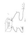
- FIG. 1is a perspective view of an electrosurgical system incorporating a power supply and an electrosurgical probe for treating articular cartilage according to the present invention
- FIG. 2schematically illustrates one embodiment of a power supply according to the present invention
- FIG. 3illustrates an electrosurgical system incorporating a plurality of active electrodes and associated current limiting elements
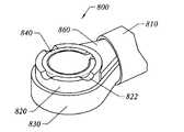
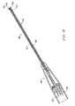
- FIG. 4is a side view of an electrosurgical probe according to the present invention.
- FIG. 5is an enlarged detailed cross-sectional view of the working end of the electrosurgical probe of FIG. 4 ;
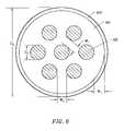
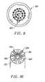
- FIG. 6is a distal end view of the probe of FIG. 4 ;
- FIGS. 7-10illustrates an alternative probe according to the present invention, incorporating an aspiration lumen
- FIG. 11is a perspective view of yet another embodiment of an electrosurgical probe according to the present invention.
- FIG. 12is a side cross-sectional view of the electrosurgical probe of FIG. 11 ;
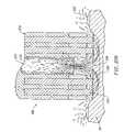
- FIG. 13is an enlarged detailed view of the distal end portion of the probe of FIG. 11 ;
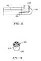
- FIGS. 14 and 16are front and end views, respectively, of the probe of FIG. 11 ;
- FIG. 15illustrates a representative insulating support member of the probe of FIG. 11 ;
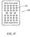
- FIG. 17is an alternative embodiment of the active electrode for the probe of FIG. 11 ;
- FIG. 18illustrates a method of ablating tissue with a probe having a plurality of active electrodes according to the present invention
- FIG. 19illustrates a method of ablating tissue with a probe having a single active electrode according to the present invention
- FIG. 20is a perspective view of another electrosurgical system incorporating a power supply, an electrosurgical probe and a supply of electrically conductive fluid for delivering the fluid to the target site;
- FIG. 21is a side view of another electrosurgical probe for use with the system of FIG. 20 ;
- FIG. 22is a distal end view of the probe of FIG. 21 ;
- FIGS. 23-26are distal end view of alternative probes according to the present invention.
- FIGS. 27A-27Care cross-sectional views of the distal portions of three different embodiments of an electrosurgical probe according to the present invention.
- FIG. 28is a cross-sectional view of the distal tip of the electrosurgical probe, illustrating electric field lines between the active and return electrodes;
- FIG. 29is a perspective view of an electrosurgical catheter system for removing body structures according to the present invention.
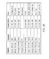
- FIG. 30is a chart listing the boiling temperature of water at varying pressures
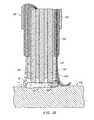
- FIG. 31depicts an electrosurgical probe having a compliant, low pressure chamber according to the present invention
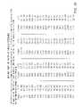
- FIG. 32lists the colors associated with the fluorescence of specific compounds.
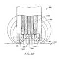
- FIG. 33illustrates an electrosurgical probe having active electrodes recessed within a plasma chamber at the distal end of the probe.
- FIG. 34illustrates an electrosurgical probe having active electrodes recessed within a number of interconnected chambers at the distal end of the probe.
- FIGS. 35A-35Billustrate a tissue treatment surface of an electrosurgical probe having spacers.
- FIGS. 36A-36Billustrate an electrosurgical probe having a vent/opening that assists in the prevention of accumulated heat between the tissue treatment surface and the tissue being treated.
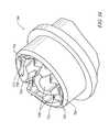
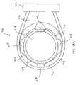
- FIGS. 37-39illustrate an electrosurgical probe having a tissue treatment end having a circular or loop configuration.
- high frequency (RF) electrical energyis applied to one or more active electrodes in the presence of electrically conductive fluid to remove and/or modify body tissue.
- the techniques of the present inventionmay be performed in a conventional open surgery environment or in a minimally invasive manner using cannulas or port access devices.
- the present inventionis useful in procedures where the tissue site is flooded or submerged with an electrically conducting fluid, such as arthroscopic surgery of the knee, shoulder, ankle, hip, elbow, hand or foot.
- the present inventionis useful in the resection and/or ablation of the meniscus and the synovial tissue within a joint during an arthroscopic procedure.
- tissues which may be treated by the system and method of the present inventioninclude, but are not limited to, prostate tissue and leiomyomas (fibroids) located within the uterus, gingival tissues and mucosal tissues located in the mouth, tumors, scar tissue, myocardial tissue, collagenous tissue within the eye or epidermal and dermal tissues on the surface of the skin.
- the present inventionis also useful for resecting tissue within accessible sites of the body that are suitable for electrode loop resection, such as the resection of prostate tissue, leiomyomas (fibroids) located within the uterus and other diseased tissue within the body.
- the present inventionis particularly useful for treating tissue in the head and neck, such as the ear, mouth, pharynx, larynx, esophagus, nasal cavity and sinuses.
- the head and neck proceduresmay be performed through the mouth or nose using speculae or gags, or using endoscopic techniques, such as functional endoscopic sinus surgery (FESS).
- FESSfunctional endoscopic sinus surgery
- These proceduresmay include the removal of swollen tissue, chronically-diseased inflamed and hypertrophic mucus linings, polyps, turbinates and/or neoplasms from the various anatomical sinuses of the skull, the turbinates and nasal passages, in the tonsil, adenoid, epi-glottic and supra-glottic regions, and salivary glands, submucus resection of the nasal septum, excision of diseased tissue and the like.
- the present inventionmay be useful for collagen shrinkage, ablation and/or hemostasis in procedures for treating swollen tissue (e.g., turbinates) or snoring and obstructive sleep apnea (e.g., soft palate, such as the uvula, or tongue/pharynx stiffening, and midline glossectomies), for gross tissue removal, such as tonsillectomies, adenoidectomies, tracheal stenosis and vocal cord polyps and lesions, or for the resection or ablation of facial tumors or tumors within the mouth and pharynx, such as glossectomies, laryngectomies, acoustic neuroma procedures and nasal ablation procedures.
- the present inventionis useful for procedures within the ear, such as stapedotomies, tympanostomies or the like.
- the present inventionmay also be useful for treating tissue or other body structures in the brain or spine.
- These proceduresinclude tumor removal, laminectomy/disketomy procedures for treating herniated disks, decompressive laminectomy for stenosis in the lumbosacral and cervical spine, medial facetectomy, posterior lumbosacral and cervical spine fusions, treatment of scoliosis associated with vertebral disease, foraminotomies to remove the roof of the intervertebral foramina to relieve nerve root compression and anterior cervical and lumbar diskectomies.
- These proceduresmay be performed through open procedures, or using minimally invasive techniques, such as thoracoscopy, arthroscopy, laparascopy or the like.
- the present inventionmay also be useful for maintaining patency in body passages subject to occlusion by invasive tissue growth.
- the apparatus and methods of the present inventionmay be used to open and maintain patency in virtually any hollow body passage which may be subject to occlusion by invasive cellular growth or invasive solid tumor growth.
- Suitable hollow body passagesinclude ducts, orifices, lumens, and the like, with exemplary body passages including the coronary arteries.
- the present inventionis particularly useful for reducing or eliminating the effects of restenosis in coronary arteries by selectively removing tissue ingrowth in or around intraluminal prostheses or stents anchored therein.
- the present inventionmay also be useful for cosmetic and plastic surgery procedures in the head and neck.
- the present inventionis particularly useful for ablation and sculpting of cartilage tissue, such as the cartilage within the nose that is sculpted during rhinoplasty procedures.
- the present inventionmay also be employed for skin tissue removal and/or collagen shrinkage in the epidermis or dermis tissue in the head and neck, e.g., the removal of pigmentations, vascular lesions (e.g., leg veins), scars, tattoos, etc., and for other surgical procedures on the skin, such as tissue rejuvenation, cosmetic eye procedures (blepharoplasties), wrinkle removal, tightening muscles for facelifts or browlifts, hair removal and/or transplant procedures, etc.
- tissue rejuvenatione.g., cosmetic eye procedures (blepharoplasties), wrinkle removal, tightening muscles for facelifts or browlifts, hair removal and/or transplant procedures, etc.
- the remaining disclosurewill be directed specifically to the treatment of tissue structures within a joint, e.g., arthroscopic surgery, but it will be appreciated that the system and method can be applied equally well to procedures involving other tissues of the body, as well as to other procedures including open procedures, intravascular procedures, interventional cardiology procedures, urology, laparascopy, arthroscopy, thoracoscopy or other cardiac procedures, cosmetic surgery, orthopedics, gynecology, otorhinolaryngology, spinal and neurologic procedures, oncology and the like.
- the body tissueis volumetrically removed or ablated.
- a high frequency voltage differenceis applied between one or more active electrode(s) and one or more return electrode(s) to non-thermally develop a high electric field intensities in the vicinity of the target tissue.
- the high electric field intensities adjacent the active electrode(s)lead to electric field induced molecular breakdown of target tissue through molecular dissociation (rather than thermal evaporation or carbonization).
- Applicantbelieves that the tissue structure is volumetrically removed through molecular disintegration of larger organic molecules into smaller molecules and/or atoms, such as hydrogen, oxygen, oxides of carbon, hydrocarbons and nitrogen compounds. This molecular disintegration completely removes the tissue structure, as opposed to dehydrating the tissue material by the removal of liquid within the cells of the tissue, as is typically the case with electrosurgical desiccation and vaporization.
- the high electric field intensitiesmay be generated by applying a high frequency voltage that is sufficient to vaporize an electrically conducting fluid over at least a portion of the active electrode(s) in the region between the distal tip of the active electrode(s) and the target tissue.
- the active electrode(s)are maintained at a low temperature to prevent thermal damage to the surrounding tissue and to improve the ionization of the electrically conductive fluid.
- the electrically conductive fluidmay be a liquid or gas, such as isotonic saline or blood, delivered to the target site, or a viscous fluid, such as a gel, applied to the target site.
- the vapor layer or vaporized regionSince the vapor layer or vaporized region has a relatively high electrical impedance, it increases the voltage differential between the active electrode tip and the tissue and causes ionization within the vapor layer due to the presence of an ionizable species (e.g., sodium when isotonic saline is the electrically conducting fluid).
- This ionizationunder the conditions described herein, induces the discharge of energetic electrons and photons from the vapor layer and to the surface of the target tissue.
- This energymay be in the form of energetic photons (e.g., ultraviolet radiation), energetic particles (e.g., electrons or ions) or a combination thereof.
- Coblation®A more detailed description of this phenomena, termed Coblation® can be found in commonly assigned U.S. Pat. No. 5,697,882 the complete disclosure of which is incorporated herein by reference.
- Applicantbelieves that the principle mechanism of tissue removal in the Coblation® mechanism of the present invention is energetic electrons or ions that have been energized in a plasma adjacent to the active electrode(s).
- a liquidis heated enough that atoms vaporize off the surface faster than they recondense, a gas is formed.
- the gasis heated enough that the atoms collide with each other and knock their electrons off in the process, an ionized gas or plasma is formed (the so-called “fourth state of matter”).
- a more complete description of plasmacan be found in Plasma Physics, by R. J. Goldston and P. H. Rutherford of the Plasma Physics Laboratory of Princeton University (1995).
- the electron mean free pathincreases to enable subsequently injected electrons to cause impact ionization within these regions of low density (i.e., vapor layers or bubbles).
- the ionic particles in the plasma layerhave sufficient energy, they accelerate towards the target tissue.
- Energy evolved by the energetic electronse.g., 3.5 eV to 5 eV
- Plasmasmay be formed by heating a small of gas and ionizing the gas by driving an electric current through it, or by shining radio waves into the gas.
- these methods of plasma formationgive energy to free electrons in the plasma directly, and then electron-atom collisions liberate more electrons, and the process cascades until the desired degree of ionization is achieved.
- the electronscarry the electrical current or absorb the radio waves and, therefore, are hotter than the ions.
- the electronswhich are carried away from the tissue towards the return electrode, carry most of the plasma's heat with them, allowing the ions to break apart the tissue molecules in a substantially non-thermal manner.
- the present inventionapplies high frequency (RF) electrical energy in an electrically conducting fluid environment to remove (i.e., resect, cut or ablate) a tissue structure and to seal transected vessels within the region of the target tissue.
- RFhigh frequency
- the present inventionis particularly useful for sealing larger arterial vessels, e.g., on the order of 1 mm or greater.
- a high frequency power supplyis provided having an ablation mode, wherein a first voltage is applied to an active electrode sufficient to effect molecular dissociation or disintegration of the tissue, and a coagulation mode, wherein a second, lower voltage is applied to an active electrode (either the same or a different electrode) sufficient to achieve hemostasis of severed vessels within the tissue.
- an electrosurgical instrumenthaving one or more coagulation electrode(s) configured for sealing a severed vessel, such as an arterial vessel, and one or more active electrodes configured for either contracting the collagen fibers within the tissue or removing (ablating) the tissue, e.g., by applying sufficient energy to the tissue to effect molecular dissociation.
- the coagulation electrode(s)may be configured such that a single voltage can be applied to coagulate with the coagulation electrode(s), and to ablate with the active electrode(s).
- the power supplyis combined with the coagulation instrument such that the coagulation electrode is used when the power supply is in the coagulation mode (low voltage), and the active electrode(s) are used when the power supply is in the ablation mode (higher voltage).
- the present inventioncomprises platinum or platinum-iridium electrodes to deliver the high frequency energy to the conductive fluid.
- the platinum/platinum-iridium electrodeshave a low resistivity and low thermal conductivity so as to minimize the production of heat in the electrodes and the electrically conductive fluid. This allows more electrical energy to be applied directly into the conductive fluid.
- one or more active electrodesare brought into close proximity to tissue at a target site, and the power supply is activated in the ablation mode such that sufficient voltage is applied between the active electrodes and the return electrode to volumetrically remove the tissue through molecular dissociation, as described below.
- the power supplyis activated in the ablation mode such that sufficient voltage is applied between the active electrodes and the return electrode to volumetrically remove the tissue through molecular dissociation, as described below.
- vessels within the tissuewill be severed. Smaller vessels will be automatically sealed with the system and method of the present invention. Larger vessels, and those with a higher flow rate, such as arterial vessels, may not be automatically sealed in the ablation mode. In these cases, the severed vessels may be sealed by activating a control (e.g., a foot pedal) to reduce the voltage of the power supply into the coagulation mode.
- a controle.g., a foot pedal
- the active electrodesmay be pressed against the severed vessel to provide sealing and/or coagulation of the vessel.
- a coagulation electrode located on the same or a different instrumentmay be pressed against the severed vessel.
- the present inventionis also useful for removing or ablating tissue around nerves, such as spinal, or cranial nerves, e.g., optic nerve, facial nerves, vestibulocochlear nerves and the like.
- nervessuch as spinal, or cranial nerves, e.g., optic nerve, facial nerves, vestibulocochlear nerves and the like.
- One of the significant drawbacks with the prior art microdebriders and lasersis that these devices do not differentiate between the target tissue and the surrounding nerves or bone. Therefore, the surgeon must be extremely careful during these procedures to avoid damage to the bone or nerves within and around the nasal cavity.
- the Coblation® process for removing tissueresults in extremely small depths of collateral tissue damage as discussed above. This allows the surgeon to remove tissue close to a nerve without causing collateral damage to the nerve fibers.
- Nervesusually comprise a connective tissue sheath, or epineurium, enclosing the bundles of nerve fibers, each bundle being surrounded by its own sheath of connective tissue (the perineurium) to protect these nerve fibers.
- the outer protective tissue sheath or epineuriumtypically comprises a fatty tissue (e.g., adipose tissue) having substantially different electrical properties than the normal target tissue, such as the turbinates, polyps, mucus tissue or the like, that are, for example, removed from the nose during sinus procedures.
- the system of the present inventionmeasures the electrical properties of the tissue at the tip of the probe with one or more active electrode(s). These electrical properties may include electrical conductivity at one, several or a range of frequencies (e.g., in the range from 1 kHz to 100 MHz), dielectric constant, capacitance or combinations of these.
- an audible signalmay be produced when the sensing electrode(s) at the tip of the probe detects the fatty tissue surrounding a nerve, or direct feedback control can be provided to only supply power to the active electrode(s) either individually or to the complete array of electrodes, if and when the tissue encountered at the tip or working end of the probe is normal tissue based on the measured electrical properties.
- the current limiting elementsare configured such that the active electrodes will shut down or turn off when the electrical impedance reaches a threshold level.
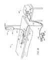
- a threshold levelis set to the impedance of the fatty tissue 4 surrounding nerves 6 .
- the active electrodeswill shut off whenever they come in contact with, or in close proximity to, nerves.
- the other active electrodeswhich are in contact with or in close proximity to nasal tissue, will continue to conduct electric current to the return electrode.
- the present inventionis capable of volumetrically removing tissue closely adjacent to nerves without impairment the function of the nerves, and without significantly damaging the tissue of the epineurium.
- One of the significant drawbacks with the prior art microdebriders and lasersis that these devices do not differentiate between the target tissue and the surrounding nerves or bone. Therefore, the surgeon must be extremely careful during these procedures to avoid damage to the bone or nerves within and around the nasal cavity.
- the Coblation® process for removing tissueresults in extremely small depths of collateral tissue damage as discussed above. This allows the surgeon to remove tissue close to a nerve without causing collateral damage to the nerve fibers.
- the Coblation® mechanism of the present inventioncan be manipulated to ablate or remove certain tissue structures, while having little effect on other tissue structures.
- the present inventionuses a technique of vaporizing electrically conductive fluid to form a plasma layer or pocket around the active electrode(s), and then inducing the discharge of energy from this plasma or vapor layer to break the molecular bonds of the tissue structure. Based on initial experiments, applicants believe that the free electrons within the ionized vapor layer are accelerated in the high electric fields near the electrode tip(s).
- the electron mean free pathincreases to enable subsequently injected electrons to cause impact ionization within these regions of low density (i.e., vapor layers or bubbles).
- Energy evolved by the energetic electronse.g., 4 to 5 eV
- the energy evolved by the energetic electronsmay be varied by adjusting a variety of factors, such as: the number of active electrodes; electrode size and spacing; electrode surface area; asperities and sharp edges on the electrode surfaces; electrode materials; applied voltage and power; current limiting means, such as inductors; electrical conductivity of the fluid in contact with the electrodes; density of the fluid; and other factors. Accordingly, these factors can be manipulated to control the energy level of the excited electrons. Since different tissue structures have different molecular bonds, the present invention can be configured to break the molecular bonds of certain tissue, while having too low an energy to break the molecular bonds of other tissue.
- fatty tissuee.g., adipose
- the present inventionin its current configuration generally does not ablate or remove such fatty tissue.
- factorsmay be changed such that these double bonds can also be broken in a similar fashion as the single bonds (e.g., increasing voltage or changing the electrode configuration to increase the current density at the electrode tips).
- a more complete description of this phenomenacan be found in co-pending U.S. patent application Ser. No. 09/032,375, filed Feb. 27, 1998, the complete disclosure of which is incorporated herein by reference.
- the present inventionalso provides systems, apparatus and methods for selectively removing tumors, e.g., facial tumors, or other undesirable body structures while minimizing the spread of viable cells from the tumor.
- Conventional techniques for removing such tumorsgenerally result in the production of smoke in the surgical setting, termed an electrosurgical or laser plume, which can spread intact, viable bacterial or viral particles from the tumor or lesion to the surgical team or to other portions of the patient's body.
- This potential spread of viable cells or particleshas resulted in increased concerns over the proliferation of certain debilitating and fatal diseases, such as hepatitis, herpes, HIV and papillomavirus.
- high frequency voltageis applied between the active electrode(s) and one or more return electrode(s) to volumetrically remove at least a portion of the tissue cells in the tumor through the dissociation or disintegration of organic molecules into non-viable atoms and molecules.
- the present inventionconverts the solid tissue cells into non-condensable gases that are no longer intact or viable, and thus, not capable of spreading viable tumor particles to other portions of the patient's brain or to the surgical staff.
- the high frequency voltageis preferably selected to effect controlled removal of these tissue cells while minimizing substantial tissue necrosis to surrounding or underlying tissue.
- the electrosurgical instrumentwill comprise a shaft having a proximal end and a distal end which supports one or more active electrode(s).
- the shaftmay assume a wide variety of configurations, with the primary purpose being to mechanically support one or more active electrode(s) and permit the treating physician to manipulate the electrode(s) from a proximal end of the shaft.
- an electrosurgical probe shaftwill be a narrow-diameter rod or tube, more usually having dimensions which permit it to be introduced through a cannula into the patient's body.
- the probe shaftwill typically have a length of at least 5 cm for open procedures and at least 10 cm, more typically being 20 cm, or longer for endoscopic procedures.
- the probe shaftwill typically have a diameter of at least 1 mm and frequently in the range from 1 to 10 mm.
- the shaftwill have any suitable length and diameter that would facilitate handling by the surgeon.
- the electrosurgical instrumentmay also be a catheter that is delivered percutaneously and/or endoluminally into the patient by insertion through a conventional or specialized guide catheter, or the invention may include a catheter having an active electrode or electrode array integral with its distal end.
- the catheter shaftmay be rigid or flexible, with flexible shafts optionally being combined with a generally rigid external tube for mechanical support. Flexible shafts may be combined with pull wires, shape memory actuators, and other known mechanisms for effecting selective deflection of the distal end of the shaft to facilitate positioning of the electrode or electrode array.
- the catheter shaftwill usually include a plurality of wires or other conductive elements running axially therethrough to permit connection of the electrode or electrode array and the return electrode to a connector at the proximal end of the catheter shaft.
- the catheter shaftmay include a guide wire for guiding the catheter to the target site, or the catheter may comprise a steerable guide catheter.
- the cathetermay also include a substantially rigid distal end portion to increase the torque control of the distal end portion as the catheter is advanced further into the patient's body.
- the electrosurgical instrumentcomprises platinum or platinum-iridium electrodes.
- the platinum/platinum-iridium electrodesprovide a superior interface with the electrically conductive medium so that there is less thermal heating and a more efficient creation of the plasma layer.
- the low resistivity and low thermal conductivity of the platinum electrodescause less thermal damage to the surrounding tissue and ablates the target tissue in a more efficient manner.
- the active electrode(s)are preferably supported within or by an inorganic insulating support positioned near the distal end of the instrument shaft.
- the return electrodemay be located on the instrument shaft, on another instrument or on the external surface of the patient (i.e., a dispersive pad). In most applications, applicant has found that it is preferably to have the return electrode on or near the shaft of the instrument to confine the electric currents to the target site. In some applications and under certain conditions, however, the invention may be practiced in a monopolar mode, with the return electrode attached to the external surface of the patient. Accordingly, the return electrode is preferably either integrated with the instrument shaft, or another instrument located in close proximity to the distal end of the instrument shaft.
- the proximal end of the instrumentwill include the appropriate electrical connections for coupling the return electrode(s) and the active electrode(s) to a high frequency power supply, such as an electrosurgical generator.
- the current flow path between the active electrodes and the return electrode(s)may be generated by submerging the tissue site in an electrical conducting fluid (e.g., within a viscous fluid, such as an electrically conductive gel) or by directing an electrically conducting fluid along a fluid path to the target site (i.e., a liquid, such as isotonic saline, hypotonic saline or a gas, such as argon).
- the conductive gelmay also be delivered to the target site to achieve a slower more controlled delivery rate of conductive fluid.
- the viscous nature of the gelmay allow the surgeon to more easily contain the gel around the target site (e.g., rather than attempting to contain isotonic saline).
- a liquid electrically conductive fluide.g., isotonic saline
- a liquid electrically conductive fluidmay be used to concurrently “bathe” the target tissue surface to provide an additional means for removing any tissue, and to cool the region of the target tissue ablated in the previous moment.
- the power supplymay include a fluid interlock for interrupting power to the active electrode(s) when there is insufficient conductive fluid around the active electrode(s). This ensures that the instrument will not be activated when conductive fluid is not present, minimizing the tissue damage that may otherwise occur.
- a fluid interlockfor interrupting power to the active electrode(s) when there is insufficient conductive fluid around the active electrode(s).
- the system of the present inventionmay include one or more suction lumen(s) in the instrument, or on another instrument, coupled to a suitable vacuum source for aspirating fluids from the target site.
- the inventionmay include one or more aspiration electrode(s) coupled to the distal end of the suction lumen for ablating, or at least reducing the volume of, non-ablated tissue fragments that are aspirated into the lumen.
- the aspiration electrode(s)function mainly to inhibit clogging of the lumen that may otherwise occur as larger tissue fragments are drawn therein.
- the aspiration electrode(s)may be different from the ablation active electrode(s), or the same electrode(s) may serve both functions.
- suctionit may be desirable to contain the excess electrically conductive fluid, tissue fragments and/or gaseous products of ablation at or near the target site with a containment apparatus, such as a basket, retractable sheath or the like.
- a containment apparatussuch as a basket, retractable sheath or the like.
- This embodimenthas the advantage of ensuring that the conductive fluid, tissue fragments or ablation products do not flow through the patient's vasculature or into other portions of the body.
- the present inventionmay use a single active platinum based electrode or an array of active platinum based electrodes spaced around the distal surface of a catheter or probe.
- the electrode arrayusually includes a plurality of independently current-limited and/or power-controlled active platinum electrodes to apply electrical energy selectively to the target tissue while limiting the unwanted heating and application of electrical energy to the surrounding tissue and environment resulting from power dissipation into surrounding electrically conductive fluids, such as blood, normal saline, and the like.
- the active electrodesmay be independently current-limited by isolating the terminals from each other and connecting each terminal to a separate power source that is isolated from the other active electrodes.
- the active electrodesmay be connected to each other at either the proximal or distal ends of the catheter to form a single wire that couples to a power source.
- each individual active electrode in the electrode arrayis electrically insulated from all other active electrodes in the array within said instrument and is connected to a power source which is isolated from each of the other active electrodes in the array or to circuitry which limits or interrupts current flow to the active electrode when low resistivity material (e.g., blood, electrically conductive saline irrigant or electrically conductive gel) causes a lower impedance path between the return electrode and the individual active electrode.
- the isolated power sources for each individual active electrodemay be separate power supply circuits having internal impedance characteristics which limit power to the associated active electrode when a low impedance return path is encountered.
- the isolated power sourcemay be a user selectable constant current source.
- a single power sourcemay be connected to each of the active electrodes through independently actuatable switches, or by independent current limiting elements, such as inductors, capacitors, resistors and/or combinations thereof.
- the current limiting elementsmay be provided in the instrument, connectors, cable, controller or along the conductive path from the controller to the distal tip of the instrument.
- the resistance and/or capacitancemay occur on the surface of the active electrode(s) due to oxide layers which form selected active electrodes (e.g., titanium or a resistive coating on the surface of metal, such as platinum).
- the tip region of the instrumentmay comprise many independent active electrodes designed to deliver electrical energy in the vicinity of the tip.
- the selective application of electrical energy to the conductive fluidis achieved by connecting each individual active electrode and the return electrode to a power source having independently controlled or current limited channels.
- the return electrode(s)may comprise a single tubular member of conductive material proximal to the electrode array at the tip which also serves as a conduit for the supply of the electrically conducting fluid between the active and return electrodes.
- the instrumentmay comprise an array of return electrodes at the distal tip of the instrument (together with the active electrodes) to maintain the electric current at the tip.
- the application of high frequency voltage between the return electrode(s) and the electrode arrayresults in the generation of high electric field intensities at the distal tips of the active electrodes with conduction of high frequency current from each individual active electrode to the return electrode.
- the current flow from each individual active electrode to the return electrode(s)is controlled by either active or passive means, or a combination thereof, to deliver electrical energy to the surrounding conductive fluid while minimizing energy delivery to surrounding (non-target) tissue.
- the application of a high frequency voltage between the return platinum electrode(s) and the active platinum electrode(s) for appropriate time intervalseffects cutting, removing, ablating, shaping, contracting or otherwise modifying the target tissue.
- the tissue volume over which energy is dissipatedi.e., a high current density exists
- the tissue volume over which energy is dissipatedmay be more precisely controlled, for example, by the use of a multiplicity of small active platinum electrodes whose effective diameters or principal dimensions range from about 10 mm to 0.01 mm, preferably from about 2 mm to 0.05 mm, and more preferably from about 1 mm to 0.1 mm.
- Electrode areas for both circular and non-circular terminalswill have a contact area (per active electrode) below 50 mm 2 for electrode arrays and as large as 75 mm 2 for single electrode embodiments.
- the contact area of each active electrodeis typically in the range from 0.0001 mm 2 to 1 mm 2 , and more preferably from 0.001 mm 2 to 0.5 mm 2 .
- the circumscribed area of the electrode array or active electrodeis in the range from 0.25 mm 2 to 75 mm 2 , preferably from 0.5 mm 2 to 40 mm 2 .
- the arraywill usually include at least two isolated active electrodes, often at least five active electrodes, often greater than 10 active electrodes and even 50 or more active electrodes, disposed over the distal contact surfaces on the shaft.
- the use of small diameter active electrodesincreases the electric field intensity and reduces the extent or depth of tissue heating as a consequence of the divergence of current flux lines which emanate from the exposed surface of each active electrode.
- the area of the tissue treatment surfacecan vary widely, and the tissue treatment surface can assume a variety of geometries, with particular areas and geometries being selected for specific applications.
- the geometriescan be planar, concave, convex, hemispherical, conical, linear “in-line” array or virtually any other regular or irregular shape.
- the active electrode(s) or active electrode(s)will be formed at the distal tip of the electrosurgical instrument shaft, frequently being planar, disk-shaped, or hemispherical surfaces for use in reshaping procedures or being linear arrays for use in cutting.
- the active electrode(s)may be formed on lateral surfaces of the electrosurgical instrument shaft (e.g., in the manner of a spatula), facilitating access to certain body structures in endoscopic procedures.
- the electrode support and the fluid outletmay be recessed from an outer surface of the instrument or handpiece to confine the electrically conductive fluid to the region immediately surrounding the electrode support.
- the shaftmay be shaped so as to form a cavity around the electrode support and the fluid outlet. This helps to assure that the electrically conductive fluid will remain in contact with the active electrode(s) and the return electrode(s) to maintain the conductive path therebetween. In addition, this will help to maintain a vapor layer and subsequent plasma layer between the active electrode(s) and the tissue at the treatment site throughout the procedure, which reduces the thermal damage that might otherwise occur if the vapor layer were extinguished due to a lack of conductive fluid. Provision of the electrically conductive fluid around the target site also helps to maintain the tissue temperature at desired levels.
- the active electrodesare spaced from the tissue a sufficient distance to minimize or avoid contact between the tissue and the vapor layer formed around the active electrodes.
- contact between the heated electrons in the vapor layer and the tissueis minimized as these electrons travel from the vapor layer back through the conductive fluid to the return electrode.
- the ions within the plasmawill have sufficient energy, under certain conditions such as higher voltage levels, to accelerate beyond the vapor layer to the tissue.
- the tissue bondsare dissociated or broken as in previous embodiments, while minimizing the electron flow, and thus the thermal energy, in contact with the tissue.
- the electrically conducting fluidshould have a threshold conductivity to provide a suitable conductive path between the return electrode and the active electrode(s).
- the electrical conductivity of the fluid(in units of milliSiemans per centimeter or mS/cm) will usually be greater than 0.2 mS/cm, preferably will be greater than 2 mS/cm and more preferably greater than 10 mS/cm.
- the electrically conductive fluidis isotonic saline, which has a conductivity of about 17 mS/cm. Applicant has found that a more conductive fluid, or one with a higher ionic concentration, will usually provide a more aggressive ablation rate.
- a saline solution with higher levels of sodium chloride than conventional saline(which is on the order of about 0.9% sodium chloride) e.g., on the order of greater than 1% or between about 3% and 20%, may be desirable.
- the inventionmay be used with different types of conductive fluids that increase the power of the plasma layer by, for example, increasing the quantity of ions in the plasma, or by providing ions that have higher energy levels than sodium ions.
- the present inventionmay be used with elements other than sodium, such as potassium, magnesium, calcium and other metals near the left end of the periodic chart.
- other electronegative elementsmay be used in place of chlorine, such as fluorine.
- the voltage difference applied between the return electrode(s) and the active electrode(s)will be at high or radio frequency, typically between about 5 kHz and 20 MHz, usually being between about 30 kHz and 2.5 MHz, preferably being between about 50 kHz and 500 kHz, often less than 350 kHz, and often between about 100 kHz and 200 kHz.
- a frequency of about 100 kHzis useful because the tissue impedance is much greater at this frequency.
- higher frequenciesmay be desirable (e.g., 400 kHz-600 kHz) to minimize low frequency current flow into the heart or the nerves of the head and neck.
- the RMS (root mean square) voltage appliedwill usually be in the range from about 5 volts to 1000 volts, preferably being in the range from about 10 volts to 500 volts, often between about 150 volts to 350 volts depending on the active electrode size, the operating frequency and the operation mode of the particular procedure or desired effect on the tissue (i.e., contraction, coagulation, cutting or ablation).
- the peak-to-peak voltage for ablation or cutting with a square wave formwill be in the range of 10 volts to 2000 volts and preferably in the range of 100 volts to 1800 volts and more preferably in the range of about 300 to 1500 volts, often in the range of about 300 volts to 800 volts peak to peak (again, depending on the electrode size, the operating frequency and the operation mode).
- Lower peak-to-peak voltageswill be used for tissue coagulation or collagen contraction and will typically be in the range from 50 to 1500, preferably 100 to 1000 and more preferably 120 to 400 volts peak-to-peak (again, these values are computed using a square wave form).
- Peak-to-peak voltagese.g., greater than about 700 volts peak-to-peak, may be desirable for ablation of harder material, such as bone, depending on other factors, such as the electrode geometries and the composition of the conductive fluid.
- the voltageis usually delivered in a series of voltage pulses or alternating current of time varying voltage amplitude with a sufficiently high frequency (e.g., on the order of 5 kHz to 20 MHz) such that the voltage is effectively applied continuously (as compared with e.g., lasers claiming small depths of necrosis, which are generally pulsed about 10 Hz to 20 Hz).
- the duty cyclei.e., cumulative time in any one-second interval that energy is applied
- the preferred power source of the present inventiondelivers a high frequency current selectable to generate average power levels ranging from several milliwatts to tens of watts per electrode, depending on the volume of target tissue being heated, and/or the maximum allowed temperature selected for the instrument tip.
- the power sourceallows the user to select the voltage level according to the specific requirements of a particular neurosurgery procedure, cardiac surgery, arthroscopic surgery, dermatological procedure, ophthalmic procedures, open surgery or other endoscopic surgery procedure.
- the power sourcemay have an additional filter, for filtering leakage voltages at frequencies below 100 kHz, particularly voltages around 60 kHz.
- a power source having a higher operating frequencye.g., 300 to 600 kHz may be used in certain procedures in which stray low frequency currents may be problematic.
- a description of one suitable power sourcecan be found in co-pending patent application Ser. Nos. 09/058,571 and 09/058,336, filed Apr. 10, 1998, the complete disclosure of both applications are incorporated herein by reference for all purposes.
- the power sourcemay be current limited or otherwise controlled so that undesired heating of the target tissue or surrounding (non-target) tissue does not occur.
- current limiting inductorsare placed in series with each independent active electrode, where the inductance of the inductor is in the range of 10 uH to 50,000 uH, depending on the electrical properties of the target tissue, the desired tissue heating rate and the operating frequency.
- capacitor-inductor (LC) circuit structuresmay be employed, as described previously in U.S. Pat. No. 5,697,909, the complete disclosure of which is incorporated herein by reference. Additionally, current limiting resistors may be selected.
- these resistorswill have a large positive temperature coefficient of resistance so that, as the current level begins to rise for any individual active electrode in contact with a low resistance medium (e.g., saline irrigant or blood), the resistance of the current limiting resistor increases significantly, thereby minimizing the power delivery from said active electrode into the low resistance medium (e.g., saline irrigant or blood).
- a low resistance mediume.g., saline irrigant or blood
- the inventionis not limited to electrically isolated active platinum electrodes, or even to a plurality of active platinum electrodes.
- the array of active platinum electrodesmay be connected to a single lead that extends through the catheter shaft to a power source of high frequency current.
- the instrumentmay incorporate a single electrode that extends directly through the catheter shaft or is connected to a single lead that extends to the power source.
- the active electrode(s)may have ball shapes (e.g., for tissue vaporization and desiccation), twizzle shapes (for vaporization and needle-like cutting), spring shapes (for rapid tissue debulking and desiccation), twisted metal shapes, annular or solid tube shapes or the like.
- the electrode(s)may comprise a plurality of filaments, rigid or flexible brush electrode(s) (for debulking a tumor, such as a fibroid, bladder tumor or a prostate adenoma), side-effect brush electrode(s) on a lateral surface of the shaft, coiled electrode(s) or the like.
- an electrosurgical catheter or probecomprises a single active platinum electrode that extends from an insulating member, e.g., ceramic, at the distal end of the shaft.
- the insulating memberis preferably a tubular structure that separates the active platinum electrode from a tubular or annular return platinum electrode positioned proximal to the insulating member and the active platinum electrode.
- the catheter or probeincludes a single active platinum electrode that can be rotated relative to the rest of the catheter body, or the entire catheter may be rotated related to the lead. The single active platinum electrode can be positioned adjacent the abnormal tissue and energized and rotated as appropriate to remove this tissue.
- the current flow path between the active platinum electrode(s) and the return platinum electrode(s)may be generated by submerging the tissue site in an electrical conducting fluid (e.g., within a viscous fluid, such as an electrically conductive gel) or by directing an electrically conducting fluid along a fluid path to the target site (i.e., a liquid, such as isotonic saline, or a gas, such as argon).
- an electrical conducting fluide.g., within a viscous fluid, such as an electrically conductive gel
- an electrically conducting fluidalong a fluid path to the target site (i.e., a liquid, such as isotonic saline, or a gas, such as argon).
- Electrosurgical system 5is generally useful for minimally invasive procedures within the body, wherein a surgical instrument is introduced through a percutaneous penetration, or through a natural opening in the patient.
- electrosurgical system 5generally includes an electrosurgical probe 20 connected to a power supply 10 for providing high frequency voltage to one or more active electrodes 42 on probe 20 .
- Probe 20includes a connector housing 44 at its proximal end, which can be removably connected to a probe receptacle 32 of a probe cable 22 .
- the proximal portion of cable 22has a connector 34 to couple probe 20 to power supply 10 .
- Power supply 10has an operator controllable voltage level adjustment 38 to change the applied voltage level, which is observable at a voltage level display 40 .
- Power supply 10also includes one or more foot pedal(s) 24 and one or more cable(s) 26 which are each removably coupled to receptacle 30 with a cable connector 28 .
- the foot pedal(s) 24may include a second pedal (not shown) for remotely adjusting the energy level applied to active electrodes 104 , and a third pedal (also not shown) for switching between an ablation mode and a sub-ablation mode (such as coagulation or contraction).
- a first foot pedal 24is used to place the power supply into the “ablation” mode and second foot pedal (not shown) places power supply 28 into the “coagulation” mode.
- the third foot pedal (not shown)allows the user to adjust the voltage level within the “ablation” mode.
- a sufficient voltageis applied to the active electrodes to establish the requisite conditions for molecular dissociation of the tissue (i.e., forming a plasma with sufficient energy to ablate tissue).
- the requisite voltage level for ablationwill vary depending on the number, size, shape and spacing of the electrodes, the distance in which the electrodes extend from the support member, etc.
- voltage level adjustment 40 or third foot pedalmay be used to adjust the voltage level to adjust the degree or aggressiveness of the ablation.
- voltage and modality of the power supplymay be controlled by other input devices.
- foot pedalsare convenient methods of controlling the power supply while manipulating the probe during a surgical procedure.
- the power supply 28applies a low enough voltage to one or more active electrodes (or one or more coagulation electrodes) to avoid vaporization of the electrically conductive fluid, formation of a plasma and subsequent molecular dissociation of the tissue.
- the surgeonmay automatically toggle the power supply between the ablation and coagulation modes by alternatively stepping on the appropriate foot pedals. This allows the surgeon to quickly move between coagulation and ablation in situ, without having to remove his/her concentration from the surgical field or without having to request an assistant to switch the power supply.
- the probetypically will simultaneously seal and/or coagulate small severed vessels within the tissue.
- the high frequency power supply of the present inventionis configured to apply a high frequency voltage of about 10 to 500 volts RMS between one or more active electrodes (and/or coagulation electrode) and one or more return electrodes.
- the power supplyapplies about 70-350 volts RMS in the ablation mode and about 20 to 90 volts in a subablation mode, preferably 45 to 70 volts in coagulation mode (these values will, of course, vary depending on the probe configuration attached to the power supply and the desired mode of operation).
- the preferred power source of the present inventiondelivers a high frequency current selectable to generate average power levels ranging from several milliwatts to tens of watts per electrode, depending on the volume of target tissue being heated, and/or the maximum allowed temperature selected for the probe tip.
- the power sourceallows the user to select the voltage level according to the specific requirements of a particular procedure, e.g., arthroscopic surgery, dermatological procedure, ophthalmic procedures, open surgery or other endoscopic surgery procedure.
- the power supplygenerally comprises a radio frequency (RF) power oscillator 100 having output connections for coupling via a power output signal 102 to the load impedance, which is represented by the electrode assembly when the electrosurgical probe is in use.
- RFradio frequency
- the RF oscillatoroperates at about 100 kHz.
- the RF oscillatoris not limited to this frequency and may operate at frequencies of about 300 kHz to 600 kHz. In particular, for cardiac applications, the RF oscillator will preferably operate in the range of about 400 kHz to about 600 kHz.
- the RF oscillatorwill generally supply a square wave signal with a crest factor of about 1 to 2.
- this signalmay be a sine wave signal or other suitable wave signal depending on the application and other factors, such as the voltage applied, the number and geometry of the electrodes, etc.
- the power output signal 102is designed to incur minimal voltage decrease (i.e., sag) under load. This improves the applied voltage to the active electrodes and the return electrode, which improves the rate of volumetric removal (ablation) of tissue.
- the switching power supply 140allows the generator to achieve high peak power output without the large size and weight of a bulky transformer.
- the architecture of the switching power supplyalso has been designed to reduce electromagnetic noise such that U.S. and foreign EMI requirements are met. This architecture comprises a zero voltage switching or crossing, which causes the transistors to turn ON and OFF when the voltage is zero. Therefore, the electromagnetic noise produced by the transistors switching is vastly reduced.
- the switching power supply 104operates at about 100 kHz.
- the controller 106may be a microprocessor or an integrated circuit.
- the power supplymay also include one or more current sensors 112 for detecting the output current.
- the power supplyis preferably housed within a metal casing which provides a durable enclosure for the electrical components therein.
- the metal casingreduces the electromagnetic noise generated within the power supply because the grounded metal casing functions as a “Faraday shield”, thereby shielding the environment from internal sources of electromagnetic noise.
- the power supplygenerally comprises a main or mother board containing generic electrical components required for many different surgical procedures (e.g., arthroscopy, urology, general surgery, dermatology, neurosurgery, etc.), and a daughter board containing application specific current-limiting circuitry (e.g., inductors, resistors, capacitors and the like).
- the daughter boardis coupled to the mother board by a detachable multi-pin connector to allow convenient conversion of the power supply to, e.g., applications requiring a different current limiting circuit design.
- the daughter boardpreferably comprises a plurality of inductors of about 200 to 400 microhenries, usually about 300 microhenries, for each of the channels supplying current to the active electrodes (see FIG. 4 ).
- current limiting inductorsare placed in series with each independent active electrode, where the inductance of the inductor is in the range of 10 uH to 50,00 uH, depending on the electrical properties of the target tissue, the desired tissue heating rate and the operating frequency.
- capacitor-inductor (LC) circuit structuresmay be employed, as described previously in co-pending PCT application No. PCT/US94/05168, the complete disclosure of which is incorporated herein by reference. Additionally, current limiting resistors may be selected.
- Power output signalmay also be coupled to a plurality of current limiting elements 96 , which are preferably located on the daughter board since the current limiting elements may vary depending on the application.
- FIG. 4illustrates an arrangement that may be used in arthroscopic procedures with a multi-electrode probe.
- a high frequency power supply 28comprises a voltage source 98 which is connected to a multiplicity of current limiting elements 96 a , 96 b , . . . 96 z , typically being inductors having an inductance in the range of about 100 to 5000 microhenries, with the particular value depending on the active electrode dimensions, the desired ablation rates, and the like.
- Capacitors having capacitance values in the range of about 200 to 10,000 picofaradsmay also be used as the current limiting elements. It would also be possible to use resistors as current limiting elements.
- the current limiting elementsany also be part of a resonant circuit structure, as described in detail in PCT/US94/05168, previously incorporated herein by reference.
- FIGS. 4-6illustrate an exemplary electrosurgical probe 20 constructed according to the principles of the present invention.
- probe 20generally includes an elongated shaft 100 which may be flexible or rigid, a handle 204 coupled to the proximal end of shaft 100 and an electrode support member 102 coupled to the distal end of shaft 100 .
- Shaft 100preferably comprises an electrically conducting material, usually a metal, such as tungsten, stainless steel alloys, platinum or its alloys, titanium or its alloys, molybdenum or its alloys, and nickel or its alloys.
- Shaft 100includes an electrically insulating jacket 108 , which is typically formed as one or more electrically insulating sheaths or coatings, such as polytetrafluoroethylene, polyimide, and the like.
- the provision of the electrically insulating jacket over the shaftprevents direct electrical contact between these metal elements and any adjacent body structure or the surgeon. Such direct electrical contact between a body structure (e.g., tendon) and an exposed electrode could result in unwanted heating and necrosis of the structure at the point of contact causing necrosis.
- Handle 204typically comprises a plastic material that is easily molded into a suitable shape for handling by the surgeon. As shown in FIG. 9 , handle 204 defines an inner cavity 208 that houses the electrical connections 250 (discussed below), and provides a suitable interface for connection to an electrical connecting cable 22 (see FIG. 1 ). As shown in FIG. 7 , the probe will typically include a coding resistor 260 having a value selected to program different output ranges and modes of operation for the power supply. This allows a single power supply to be used with a variety of different probes in different applications (e.g., dermatology, cardiac surgery, neurosurgery, arthroscopy, etc).
- the probe 20further includes an identification element that is characteristic of the particular electrode assembly so that the same power supply 28 can be used for different electrosurgical operations.
- the probe 20includes a voltage reduction element or a voltage reduction circuit for reducing the voltage applied between the active electrodes 104 and the return electrode 112 .
- the voltage reduction elementserves to reduce the voltage applied by the power supply so that the voltage between the active electrodes and the return electrode is low enough to avoid excessive power dissipation into the electrically conducting medium and/or ablation of the tissue at the target site.
- the voltage reduction elementprimarily allows the electrosurgical probe 20 to be compatible with other ArthroCare generators that are adapted to apply higher voltages for ablation or vaporization of tissue.
- the voltage reduction elementwill serve to reduce a voltage of about 100 to 135 volts rms (which is a setting of 1 on the ArthroCare Models 970, 980 and 2000 Generators) to about 45 to 60 volts rms, which is a suitable voltage for contraction of tissue without ablation (e.g., molecular dissociation) of the tissue.
- the probewill typically not require a voltage reduction element.
- the probemay include a voltage increasing element or circuit, if desired.
- an electrode support member 102extends from the distal end of shaft 100 (usually about 1 to 20 mm), and provides support for a plurality of electrically isolated active electrodes 120 . Electrode support member 102 and active electrodes 120 are preferably secured to a tubular support member 122 within shaft 100 by adhesive 124 .
- the active electrodes 120may be constructed using round, square, rectangular or other shaped conductive metals. In a preferred embodiment, the active electrodes comprise platinum. In some embodiments, the active electrodes further include between 1% and 30% iridium, and preferably between 5% and 15% iridium.
- Electrode support member 102is preferably a ceramic, glass or glass/ceramic composition (e.g., aluminum oxide, titanium nitride or the like).
- electrode support member 620may include the use of high-temperature biocompatible plastics such as polyether-ether-keytone (PEEK) manufactured by Vitrex International Products, Inc. or polysulfone manufactured by GE Plastics.
- the adhesive 620may, by way of example, be an epoxy (e.g., Master Bond EP42HT manufactured by Master Bond) or a silicone-based adhesive.
- FIG. 6illustrates one embodiment of the working end of probe 20 .
- a total of 7 circular active platinum electrodes or active platinum electrodes 120are shown in a symmetrical pattern having an active electrode diameter, D 1 in the range from 0.05 mm to 1.5 mm, more preferably in the range from 0.1 mm to 0.75 mm.
- the interelectrode spacings, W 1 and W 2are preferably in the range from 0.1 mm to 1.5 mm and more preferably in the range from 0.2 mm to 0.75 mm.
- the distance between the outer perimeter of the active electrode 120 and the perimeter of the electrode support member, W 3is preferably in the range from 0.1 mm to 1.5 mm and more preferably in the range from 0.2 mm to 0.75 mm.
- the overall diameter, D 2 of the working end of probe 20is preferably in the range from 0.5 mm to 10 mm and more preferably in the range from 0.5 mm to 5 mm.
- the shape of the active electrodesmay be round, square, triangular, hexagonal, rectangular, tubular, flat strip and the like and may be arranged in a circularly symmetric pattern as shown in FIG. 6 or may, by way of example, be arranged in a rectangular, square, linear pattern, or the like.
- probe 20includes a tubular cannula 122 extending along shaft 100 radially outward from support member 102 and active electrodes 120 .
- the material for cannula 122may be selected from a group of electrically conductive metals so that the cannula 122 functions as both a structural support member for the array of active electrodes 120 as well as a return electrode 112 .
- the support member 122is connected to an electrical lead wire (not shown) at its proximal end within a connector housing (not shown) and continues via a suitable connector to power supply 28 to provide electrical continuity between one output pole of high frequency generator 28 and said return electrode 112 .
- the cannula 122may be selected from the group including stainless steel, copper-based alloys, titanium or its alloys, and nickel-based alloys.
- the thickness of the cannula 122is preferably in the range from 0.08 mm to 1.0 mm and more preferably in the range from 0.05 mm to 0.4 mm.
- cannula 122is covered with an electrically insulating sleeve 108 to protect the patient's body from the electric current.
- Electrically insulating sleeve 108may be a coating (e.g., nylon) or heat shrinkable plastic (e.g., fluropolymer or polyester).
- the proximal portion of the cannula 122is left exposed to function as the return electrode 112 .
- the length of the return electrode 112 , L 5is preferably in the range from 1 mm to 30 mm and more preferably in the range from 2 mm to 20 mm.
- the spacing between the most distal portion of the return electrode 112 and the plane of the tissue treatment surface of the electrode support member 120 , L 1is preferably in the range from 0.5 mm to 30 mm and more preferably in the range from 1 mm to 20 mm.
- the thickness of the electrically insulating sleeve 108is preferably in the range from 0.01 mm to 0.5 mm and more preferably in the range from 0.02 mm to 0.2 mm.
- the electrically conducting fluidis delivered from a fluid delivery element (not shown) that is separate from probe 20 .
- a fluid delivery element(not shown) that is separate from probe 20 .
- the body cavitywill be flooded with isotonic saline and the probe 20 will be introduced into this flooded cavity. Electrically conducting fluid will be continually resupplied to maintain the conduction path between return electrode 112 and active electrodes 102 .
- FIGS. 7-10illustrate another embodiment of the present invention incorporating an aspiration lumen and a loop electrode designed to ablate tissue fragments as they as aspirated into the lumen.
- electrosurgical probe 20includes an elongated shaft 100 which may be flexible or rigid, a handle 204 coupled to the proximal end of shaft 100 and an electrode support member 102 coupled to the distal end of shaft 100 .
- probe 20includes an active loop electrode 203 and a return electrode 212 spaced proximally from active loop electrode 203 .
- the probe 200further includes a suction lumen 220 for aspirating excess fluids, bubbles, tissue fragments, and/or products of ablation from the target site.
- suction lumen 220extends through support member 102 to a distal opening 222 , and extends through shaft 201 and handle 204 to an external connector 224 for coupling to a vacuum source.
- the vacuum sourceis a standard hospital pump that provides suction pressure to connector 224 and lumen 220 .
- Electrode support member 102extends from the distal end of shaft 201 usually about 1 to 20 mm), and provides support for loop electrode 203 and a ring electrode 204 (see FIG. 22 ).
- loop electrode 203has first and second ends extending from the electrode support member 102 . The first and second ends are each coupled to, or integral with, one or more connectors, e.g., wires (not shown), that extend through the shaft of the probe to its proximal end for coupling to the high frequency power supply.
- the loop electrodeusually extends about 0.5 to about 10 mm from the distal end of support member, preferably about 1 to 2 mm.
- Loop electrode 203usually extends further away from the support member than the ring electrode 204 to facilitate ablation of tissue. As discussed below, loop electrode 203 is especially configured for tissue ablation, while the ring electrode 204 ablates tissue fragments that are aspirated into suction lumen 220 .
- ring electrode 204preferably comprises a tungsten or titanium wire having two ends 230 , 232 coupled to electrical connectors (not shown) within support member 102 .
- the wireis bent to form one-half of a figure eight, thereby form a ring positioned over opening 222 of suction lumen 220 .
- This ringinhibits passage of tissue fragments large enough to clog suction lumen 220 .
- voltage applied between ring electrode 204 and return electrode 212provide sufficient energy to ablate these tissue fragments into smaller fragments that are then aspirated through lumen 220 .
- ring electrode 204 and loop electrode 203are electrically isolated from each other. However, these electrodes 204 , 203 may be electrically coupled in some applications.
- FIGS. 11-17illustrate another embodiment of the present invention including an electrosurgical probe 300 incorporating an active screen electrode 302 .
- probe 300includes an elongated shaft 304 which may be flexible or rigid, a handle 306 coupled to the proximal end of shaft 304 and an electrode support member 308 coupled to the distal end of shaft 304 .
- Probe 300further includes an active screen electrode 302 and a return electrode 310 spaced proximally from active screen electrode 302 .
- active screen electrode 302 and support member 308are configured such that the active electrode 302 is positioned on a lateral side of the shaft 304 (e.g., 90 degrees from the shaft axis) to allow the physician to access tissue that is offset from the axis of the portal or arthroscopic opening into the joint cavity in which the shaft 304 passes during the procedure.
- probe 300includes an electrically insulating cap 320 coupled to the distal end of shaft 304 and having a lateral opening 322 for receiving support member 308 and screen electrode 302 .
- the probe 300further includes a suction connection tube 314 for coupling to a source of vacuum, and an inner suction lumen 312 ( FIG. 12 ) for aspirating excess fluids, tissue fragments, and/or products of ablation (e.g., bubbles) from the target site.
- suction lumen 312allows the surgeon to draw loose tissue, e.g., synovial tissue, towards the screen electrode 302 , as discussed above.
- the vacuum sourceis a standard hospital pump that provides suction pressure to connection tube 314 and lumen 312 .
- a pumpmay also be incorporated into the high frequency power supply. As shown in FIGS.
- internal suction lumen 312which preferably comprises peek tubing, extends from connection tube 314 in handle 306 , through shaft 304 to an axial opening 316 in support member 308 , through support member 308 to a lateral opening 318 .
- Lateral opening 318contacts screen electrode 302 , which includes a plurality of holes 324 ( FIG. 214 for allowing aspiration therethrough, as discussed below.
- handle 306defines an inner cavity 326 that houses the electrical connections 328 (discussed above), and provides a suitable interface for connection to an electrical connecting cable 22 (see FIG. 1 ).
- the probewill also include a coding resistor 330 having a value selected to program different output ranges and modes of operation for the power supply. This allows a single power supply to be used with a variety of different probes in different applications (e.g., dermatology, cardiac surgery, neurosurgery, arthroscopy, etc).
- electrode support member 308preferably comprises an inorganic material, such as glass, ceramic, silicon nitride, alumina or the like, that has been formed with lateral and axial openings 318 , 316 for suction, and with one or more smaller holes 330 for receiving electrical connectors 332 .
- support member 308has a cylindrical shape for supporting a circular screen electrode 302 .
- screen electrode 302may have a variety of different shapes, such as the rectangular shape shown in FIG. 17 , which may change the associated shape of support member 308 . As shown in FIG.
- electrical connectors 332extend from connections 328 , through shaft 304 and holes 330 in support member 308 to screen electrode 302 to couple the active electrode 302 to a high frequency power supply.
- screen electrode 302is mounted to support member 308 by ball wires 334 that extend through holes 336 in screen electrode 302 and holes 330 in support member 308 .
- Ball wires 334function to electrically couple the screen 302 to connectors 332 and to secure the screen 302 onto the support member 308 .
- a variety of other methodsmay be used to accomplish these functions, such as nailhead wires, adhesive and standard wires, a channel in the support member, etc.
- the screen electrodewill preferably comprise platinum or a platinum-iridium alloy.
- the screen electrode 302will comprise a conductive material, such as
- Screen electrode 302will usually have a diameter in the range of about 0.5 to 8 mm, preferably about 1 to 4 mm, and a thickness of about 0.05 to about 2.5 mm, preferably about 0.1 to 1 mm. Electrode 302 will comprise a plurality of holes 324 having sizes that may vary depending on the particular application and the number of holes (usually from one to 50 holes, and preferably about 3 to 20 holes).
- Holes 324will typically be large enough to allow ablated tissue fragments to pass through into suction lumen 312 , typically being about 2 to 30 mils in diameter, preferably about 5 to 20 mils in diameter. In some applications, it may be desirable to only aspirate fluid and the gaseous products of ablation (e.g., bubbles) so that the holes may be much smaller, e.g., on the order of less than 10 mils, often less than 5 mils.
- probe 300is manufactured as follows: screen electrode 302 is placed on support member 308 so that holes 324 are lined up with holes 330 . One or more ball wires 334 are inserted through these holes, and a small amount of adhesive (e.g., epotek) is placed around the outer face of support member 308 . The ball wires 334 are then pulled until screen 302 is flush with support member 308 , and the entire sub-assembly is cured in an oven or other suitable heating mechanism. The electrode-support member sub-assembly is then inserted through the lateral opening in cap 320 and adhesive is applied to the peek tubing suction lumen 312 . The suction lumen 312 is then placed through axial hole 316 in support member 308 and this sub-assembly is cured. The return electrode 310 (which is typically the exposed portion of shaft 304 ) is then adhered to cap 320 .
- adhesivee.g., epotek
- FIGS. 18 and 19illustrate use of one of the probes 350 of the present invention for ablating tissue.
- the distal portion of probe 350is introduced to the target site (either endoscopically, through an open procedure, or directly onto the patient's skin) and active electrode(s) 352 are positioned adjacent tissue ( FIG. 19 illustrates a probe having a single active electrode 352 , while FIG. 18 illustrates multiple active electrodes 352 ).
- the target siteis immersed in electrically conductive fluid, such that the conductive fluid generates a current flow path (see current flux lines 358 ) between return electrode 356 and the active electrode(s) 352 , and the zone between the tissue 354 and electrode support 380 is constantly immersed in the fluid.
- the power supply(not shown) is then turned on and adjusted such that a high frequency voltage difference is applied between active electrode(s) 352 and return electrode 356 .
- the high frequency voltageis sufficient to non-thermally convert the electrically conductive fluid between the target tissue 354 and active electrode(s) 352 into an ionized vapor layer or plasma 360 .
- the applied voltage difference between active electrode(s) 352 and the target tissue 354i.e., the voltage gradient across the plasma layer 360
- charged particles in the plasmaviz., electrons
- these charged particlesgain sufficient energy to non-thermally cause dissociation of the molecular bonds within tissue structures.
- This molecular dissociationis accompanied by the volumetric removal (i.e., ablative sublimation) of tissue and the production of low molecular weight gases 366 , such as oxygen, nitrogen, carbon dioxide, hydrogen and methane.
- gases 366such as oxygen, nitrogen, carbon dioxide, hydrogen and methane.
- electrosurgical system 411for treatment of tissue in ‘dry fields’ will now be described in detail.
- system 411may also be used in ‘wet field’, i.e., the target site is immersed in electrically conductive fluid.
- this systemis particularly useful in ‘dry fields’ where the fluid is preferably delivered through electrosurgical probe to the target site.
- electrosurgical system 411generally comprises an electrosurgical handpiece or probe 410 connected to a power supply 428 for providing high frequency voltage to a target site and a fluid source 421 for supplying electrically conducting fluid 450 to probe 410 .
- electrosurgical system 411may include an endoscope (not shown) with a fiber optic head light for viewing the surgical site, particularly in sinus procedures or procedures in the ear or the back of the mouth.
- the endoscopemay be integral with probe 410 , or it may be part of a separate instrument.
- the system 411may also include a vacuum source (not shown) for coupling to a suction lumen or tube 460 (see FIG. 21 ) in the probe 410 for aspirating the target site.
- probe 410generally includes a proximal handle 419 and an elongate shaft 418 having an array 412 of active electrodes 458 at its distal end.
- a connecting cable 434has a connector 426 for electrically coupling the active electrodes 458 to power supply 428 .
- the active electrodes 458are electrically isolated from each other and each of the terminals 458 is connected to an active or passive control network within power supply 428 by means of a plurality of individually insulated conductors (not shown).
- a fluid supply tube 415is connected to a fluid tube 414 of probe 410 for supplying electrically conducting fluid 450 to the target site.
- FIGS. 21 and 22illustrate an exemplary embodiment of an electrosurgical probe 410 for use with the system 411 of FIG. 20 .
- the probe 410includes a shaft 100 , a proximal handle 404 , a distal support member 468 and a platinum electrode assembly including a platinum return electrode 462 proximally spaced from one or more active platinum electrodes 464 .
- the return electrode 462is not directly connected to active electrodes 464 .
- electrically conducting fluide.g., isotonic saline
- probe 410includes a fluid connector 435 for coupling a fluid tube 433 to a source of electrically conductive fluid, such as a pump or a gravity driven fluid source.
- the electrically conducting fluidis delivered through fluid tube 433 to opening 437 , as described above. Electrically conducting fluid will be continually resupplied to maintain the conduction path between return electrode 462 and active electrodes 464 .
- fluid tube 433comprises peek tubing or a similar type of tubing material.
- the fluid pathmay be formed in probe 410 by, for example, an inner lumen or an annular gap between the return electrode 462 and a tubular support member within shaft 100 (see FIG. 22 ). This annular gap may be formed near the perimeter of the shaft 100 such that the electrically conducting fluid tends to flow radially inward towards the target site, or it may be formed towards the center of shaft 100 so that the fluid flows radially outward.
- a fluid sourcee.g., a bag of fluid elevated above the surgical site or suitable pumping device
- a fluid supply tube(not shown) that may or may not have a controllable valve.
- the electrically isolated active electrodes 464are spaced apart over tissue treatment surface 470 of electrode support member 468 .
- the tissue treatment surface and individual active electrodes 464will usually have dimensions within the ranges set forth above.
- the tissue treatment surface 470has a circular cross-sectional shape with a diameter in the range of about 1 mm to 20 mm.
- the individual active electrodes 464preferably extend outward from tissue treatment surface 474 by a distance of about 0.0 to 4 mm, usually about 0.2 to 2 mm. Applicant has found that this configuration increases the high electric field intensities and associated current densities around active electrodes 464 to facilitate the ablation of tissue as described in detail above.
- the active electrodes 464may be flush with tissue treatment surface 474 , be recessed from treatment surface 474 , or extend further outward than 2 mm, depending on the desired treatment outcome.
- the probeincludes a single, larger opening 409 in the center of tissue treatment surface 470 , and a plurality of active electrodes (e.g., about 3 to 15 active electrodes) around the perimeter of surface 470 .
- the probemay include a single, annular, or partially annular, active electrode at the perimeter of the tissue treatment surface.
- the central opening 409is coupled to a suction lumen 425 within shaft 100 and a suction tube 461 ( FIG. 21 ) for aspirating tissue, fluids, and/or gases from the target site.
- the electrically conductive fluidgenerally flows radially inward past active electrodes 464 and then back through the opening 209 . Aspirating the electrically conductive fluid during surgery allows the surgeon to see the target site, and it prevents the dispersal of gases, bone tissue fragments and/or calcified deposits into the patient's body.
- the probe 410will also include one or more aspiration electrode(s) (not shown) coupled to the aspiration lumen 425 for inhibiting clogging during aspiration of tissue fragments from the surgical site.
- aspiration electrode(s)not shown
- FIGS. 23-26illustrate alternative embodiments of the probe 410 , each one incorporating one or more aspiration electrodes positioned in front of opening 409 of aspiration lumen 425 .
- two of the active electrodes 464comprise loop electrode 480 that cross over the distal opening 609 .
- the electrodesmay have shapes other than loops, such as the coiled configurations shown in FIGS. 24 and 25 .
- the electrodesmay be formed within suction lumen proximal to the distal opening 409 , as shown in FIG. 26 .
- the main function of loop electrodes 480is to ablate portions of tissue that are drawn into the suction lumen to prevent clogging of the lumen.
- Loop electrodes 4800are electrically isolated from the other active electrodes 464 , which can be referred to hereinafter as the ablation electrodes 464 .
- Loop electrodes 480may or may not be electrically isolated from each other. Loop electrodes 480 will usually extend only about 0.05 to 4 mm, preferably about 0.1 to 1 mm from the tissue treatment surface of electrode support member 464 .
- loop electrodes 480are electrically isolated from the other active electrodes 464 , and they must be separately activated at the power supply 28 . In other embodiments, loop electrodes 480 will be activated at the same time that active electrodes 464 are activated. In this case, applicant has found that the plasma layer typically forms when tissue is drawn adjacent to loop electrodes 480 .
- the aspiration electrodesmay comprise a pair of coiled electrodes 482 that extend across distal opening 409 of the suction lumen.
- the larger surface area of the coiled electrodes 482usually increases the effectiveness of the electrodes 482 on tissue fragments passing through opening 409 .
- the aspiration electrodecomprises a single coiled electrode 484 passing across the distal opening 409 of suction lumen. This single electrode 484 may be sufficient to inhibit clogging of the suction lumen.
- the aspiration electrodesmay be positioned within the suction lumen proximal to the distal opening 609 .
- these electrodesare close to opening 409 so that tissue does not clog the opening 609 before it reaches electrodes 484 .
- a separate return electrode(not shown) may be provided within the suction lumen to confine the electric currents therein.
- an aspiration electrode 490within the aspiration lumen 492 of the probe.
- the electrode 490is positioned just proximal of distal opening 409 so that the tissue fragments are ablated as they enter lumen 492 .
- the aspiration electrode 490comprises a loop electrode that stretches across the aspiration lumen 492 .
- the return electrode 494is located outside of the probe as in the previously embodiments.
- the return electrode(s)may be located within the aspiration lumen 492 with the aspiration electrode 490 .
- the inner insulating coating 493may be exposed at portions within the lumen 492 to provide a conductive path between this exposed portion of return electrode 494 and the aspiration electrode 490 .
- the latter embodimenthas the advantage of confining the electric currents to within the aspiration lumen.
- itis usually easier to maintain a conductive fluid path between the active and return electrodes in the latter embodiment because the conductive fluid is aspirated through the aspiration lumen 492 along with the tissue fragments.
- gaseswill be aspirated through opening 409 and suction tube 460 ( FIG. 21 ) to a vacuum source.
- excess electrically conductive fluid, and other fluidse.g., blood
- tissue fragmentsare also aspirated through opening 409 into suction lumen and tube 460 during the procedure. These tissue fragments are ablated or dissociated with loop electrodes 480 ( FIG. 23 ) with a similar mechanism described above.
- loop electrodes 480As electrically conductive fluid and tissue fragments are aspirated into loop electrodes 480 , these electrodes are activated so that high frequency voltage is applied to loop electrodes 480 and return electrode 462 (of course, the probe may include a different, separate return electrode for this purpose).
- the voltageis sufficient to vaporize the fluid, and create a plasma layer between loop electrodes 480 and the tissue fragments so that portions of the tissue fragments are ablated or removed. This reduces the volume of the tissue fragments as they pass through suction lumen to minimize clogging of the lumen.
- the present inventionis particularly useful for removing elastic tissue, such as the synovial tissue found in joints.
- this elastic synovial tissuetends to move away from instruments within the conductive fluid, making it difficult for conventional instruments to remove this tissue.
- the probeis moved adjacent the target synovial tissue, and the vacuum source is activated to draw the synovial tissue towards the distal end of the probe.
- the aspiration and/or active electrodesare then energized to ablate this tissue. This allows the surgeon to quickly and precisely ablate elastic tissue with minimal thermal damage to the treatment site.
- FIGS. 27A-27Cschematically illustrate the distal portion of three different embodiments of probe 490 according to the present invention.
- active electrodes 504are anchored in a support matrix 502 of suitable insulating material (e.g., ceramic or glass material, such as alumina, silicon nitride zirconia and the like) which could be formed at the time of manufacture in a flat, hemispherical or other shape according to the requirements of a particular procedure.
- suitable insulating materiale.g., ceramic or glass material, such as alumina, silicon nitride zirconia and the like
- the preferred support matrix materialis alumina, available from Kyocera Industrial Ceramics Corporation, Elkgrove, Ill., because of its high thermal conductivity, good thermal shock resistance, good electrically insulative properties, high flexural modulus, resistance to carbon tracking, biocompatibility, and high melting point.
- the support matrix 502is adhesively joined to a tubular support member 578 that extends most or all of the distance between matrix 502 and the proximal end of probe 490 .
- Tubular member 578preferably comprises an electrically insulating material, such as an epoxy or silicone-based material.
- active electrodes 504extend through pre-formed openings in the support matrix 502 so that they protrude above tissue treatment surface 512 by the desired distance.
- the electrodesare then bonded to the tissue treatment surface 512 of support matrix 502 , typically by an inorganic sealing material 580 .
- Sealing material 580is selected to provide effective electrical insulation, and good adhesion to both the alumina matrix 502 and the active electrodes (e.g., titanium, tungsten, molybdenum, platinum, etc.). Sealing material 580 additionally should have a compatible thermal expansion coefficient and a melting point well below that of the metal active electrodes and the ceramic support matrix, typically being a glass or glass ceramic.
- return electrode 512comprises an annular member positioned around the exterior of shaft 100 of probe 490 .
- Return electrode 512may fully or partially circumscribe tubular support member 578 to form an annular gap 554 therebetween for flow of electrically conducting fluid 550 therethrough, as discussed below.
- Gap 554preferably has a width in the range of 0.1 mm to 4 mm.
- probemay include a plurality of longitudinal ribs between support member 578 and return electrode 512 to form a plurality of fluid lumens extending along the perimeter of shaft 100 . In this embodiment, the plurality of lumens will extend to a plurality of openings.
- Return electrode 512is disposed within an electrically insulative jacket 518 , which is typically formed as one or more electrically insulative sheaths or coatings, such as polytetrafluoroethylene, polyamide, and the like.
- the provision of the electrically insulative jacket 518 over return electrode 512prevents direct electrical contact between return electrode 512 and any adjacent body structure. Such direct electrical contact between a body structure (e.g., tendon) and an exposed electrode member 512 could result in unwanted heating and necrosis of the structure at the point of contact causing necrosis.
- return electrode 512is not directly connected to active electrodes 504 .
- electrically conducting fluid 550e.g., isotonic saline
- Fluid path 583is formed by annular gap 554 between outer return electrode 512 and tubular support member 578 .
- the electrically conducting fluid 550 flowing through fluid path 583provides a pathway for electrical current flow between active electrodes 504 and return electrode 512 , as illustrated by the current flux lines 560 in FIG. 6A .
- FIG. 27Billustrates another alternative embodiment of electrosurgical probe 490 which has a return electrode 512 positioned within tubular member 578 .
- Return electrode 512is preferably a tubular member defining an inner lumen 557 for allowing electrically conducting fluid 550 (e.g., isotonic saline) to flow therethrough in electrical contact with return electrode 512 .
- electrically conducting fluid 550e.g., isotonic saline
- a voltage differenceis applied between active electrodes 504 and return electrode 512 resulting in electrical current flow through the electrically conducting fluid 550 as shown by current flux lines 560 .
- tissue 552becomes ablated or transected in zone 588 .
- FIG. 27Cillustrates another embodiment of probe 490 that is a combination of the embodiments in FIGS. 27A and 27B .
- this probeincludes both an inner lumen 557 and an outer gap or plurality of outer lumens 554 for flow of electrically conductive fluid.
- the return electrode 512may be positioned within tubular member 578 as in FIG. 27B , outside of tubular member 578 as in FIG. 27A , or in both locations.
- FIG. 28illustrates the current flux lines associated with an electric field 520 applied between the active and return electrodes 504 , 512 when a voltage is applied therebetween.
- the electric field intensityis substantially higher in the region 588 at the tip of the electrode 504 because the current flux lines are concentrated in these regions.
- This high electric field intensityleads to induced molecular breakdown of the target tissue through molecular dissociation.
- charged particlesnot shown in the plasma (viz., electrons) are accelerated towards the tissue. At sufficiently high voltage differences, these charged particles gain sufficient energy to cause dissociation of the molecular bonds within tissue structures.
- This molecular dissociationis accompanied by the volumetric removal (i.e., ablative sublimation) of tissue and the production of low molecular weight gases 526 , such as oxygen, nitrogen, carbon dioxide, hydrogen and methane.
- gases 526such as oxygen, nitrogen, carbon dioxide, hydrogen and methane.
- the electrosurgical devicemay also be configured as an elongate catheter system 600 including portions with sufficient flexibility to permit introduction into the body and to the target site through one or more vascular lumen(s).
- catheter system 600generally comprises an electrosurgical catheter 660 connected to a power supply 628 by an interconnecting cable 686 for providing high frequency voltage to a target tissue site and an irrigant reservoir or source 600 for providing electrically conducting fluid to the target site.
- Catheter 660generally comprises an elongate, flexible shaft body 662 including a tissue removing or ablating region 664 at the distal end of body 662 .
- the proximal portion of catheter 660includes a multi-lumen fitment 614 which provides for interconnections between lumens and electrical leads within catheter 660 and conduits and cables proximal to fitment 614 .
- a catheter electrical connector 696is removably connected to a distal cable connector 694 which, in turn, is removably connectable to generator 628 through connector 692 .
- One or more electrically conducting lead wires (not shown) within catheter 660extend between one or more active electrodes 663 at tissue ablating region 664 and one or more corresponding electrical terminals (also not shown) in catheter connector 696 via active electrode cable branch 687 .
- one or more return electrodes 666 at tissue ablating region 664are coupled to a return electrode cable branch 689 of catheter connector 696 by lead wires (not shown).
- lead wires(not shown)
- a single cable branch(not shown) may be used for both active and return electrodes.
- Catheter body 662may include reinforcing fibers or braids (not shown) in the walls of at least the distal ablation region 664 of body 662 to provide responsive torque control for rotation of active electrodes during tissue engagement.
- This rigid portion of the catheter body 662preferably extends only about 7 to 10 mm while the remainder of the catheter body 662 is flexible to provide good trackability during advancement and positioning of the electrodes adjacent target tissue.
- Conductive fluid 630is provided to tissue ablation region 664 of catheter 660 via a lumen (not shown in FIG. 29 ) within catheter 660 .
- Fluidis supplied to lumen from the source along a conductive fluid supply line 602 and a conduit 603 , which is coupled to the inner catheter lumen at multi-lumen fitment 614 .
- the source of conductive fluide.g., isotonic saline
- the source of conductive fluidmay be an irrigant pump system (not shown) or a gravity-driven supply, such as an irrigant reservoir 600 positioned several feet above the level of the patient.
- a control valve 604may be positioned at the interface of fluid supply line 602 and conduit 603 to allow manual control of the flow rate of electrically conductive fluid 630 .
- a metering pump or flow regulatormay be used to precisely control the flow rate of the conductive fluid.
- System 600further includes an aspiration or vacuum system (not shown) to aspirate liquids and gases from the target site.
- the aspiration systemwill usually comprise a source of vacuum coupled to fitment 614 by an aspiration connector 605 .
- volumetric tissue removalwhile maintaining relatively low plasma temperatures, e.g., below 100° C., below 80° C., or even below 50° C.
- This low temperature tissue removalreduces the likelihood of collateral thermal damage to those cells or tissue surrounding the target tissue.
- platinum or platinum-iridium electrodesare used to maintain the low plasma temperature. Because platinum has a low resistivity and does not corrode, the electrical energy is transferred to the conductive liquid in a substantially non-thermal manner.
- Boiling temperature of a liquidis defined as the temperature of a liquid at which its vapor pressure is equal to or very slightly greater than the atmospheric or external pressure of the environment.
- the boiling temperature of water at sea level (1 atms)is 100° C.
- a variety of fluids and/or solutionshave boiling temperatures below 100° C.
- methanolhas a boiling temperature of 64.7° C.
- the fluid or solutionwill comprise an electrically conductive, biocompatible material that is not toxic or harmful to the patient.
- the liquid solutionbe an azeotropic. Azeotropic mixtures of two or more substances behave like a single substance in that the vapor produced by partial evaporation of liquid has the same composition as the liquid. This should prevent the uneven depletion of one solution component faster than the other, which may over the course of treatment, undesirably change the boiling temperature.
- Another technique for lowering the vaporization temperature of the electrically conductive fluidinvolves reducing the external vapor pressure of the air or gas near the target site. As illustrated in the chart of FIG. 30 , the boiling temperature of water decreases with decreases pressure. Thus, by creating a sub-atmospheric environment in the electrically conductive fluid near the active electrode(s), the temperature required for vaporization of the fluid will decrease.
- a smaller, compliant chamber or balloon 720can be attached to the area of the patient to be treated.
- the compliant chamber 720has sufficient slack to allow the electrosurgical probe 710 to move freely about the area covered.
- Adhesive 722 or other attachment devicesmay be used to secure the chamber 720 to the patient or to the probe.
- the chambermay comprise a material such as glass or a transparent polymer that allows for clear viewing of the working end of the probe 710 .
- the chamber 720may include a clear, hardened portion 724 that also functions to maintain the slack in the chamber 720 away from the working end of the probe 710 .
- the hardened portion 724may assume a variety of shapes such as dome, cylindrical, circular, and the like.
- the ions in the plasmatypically fluoresce with a yellow-orange color. It is believed that the color results from the excitation of the ionic particles as they are accelerated towards the target tissue.
- the color of the fluorescenceat least partly depends on the ionic material included in the solution, as illustrated in FIG. 32 .
- the fluorescence colorcomprise blue, green, purple or another color that is not generally associated with conventional electrosurgical arcing or other thermal processes. It may be further desirable to simulate the color of excimer laser light to reassure the patient and user that the process involves cold ablation mechanisms. Accordingly, those compounds having potassium, copper, and barium may be selected.
- solutions of potassium chloridein the range of about 0.5 to 5%
- the material usedwill have ionizing qualities similar to the sodium chloride used in saline solutions.
- concentration of these materialswill be varied depending on the strength of volumetric tissue removal desired.
- spectrophotometric analysis of the plasma created using a saline solution reversalis a broad peak near 308 nm (same wavelength as the XeCl excimer laser) and a yet higher peak intensity at 588 nm (giving rise to the yellow/orange color of the saline plasma). With the proper selection of metal salts or ionic material, more of the wavelength may be concentrated near the 308 nm wavelength of the excimer laser.
- Applicanthas found that increasing the current densities around the active electrode(s) can lead to higher energy levels in the ionized plasma. This, in turn, allows the ionized plasma to break stronger molecular bonds, such as those present in bone or calcified fragments. Since the electrically conductive fluid between the target site and active electrode(s) is transformed into an ionized vapor layer or plasma, the number of charged particles which can be accelerated against the target also determines the removal rate. In addition, the conductivity of the fluid may have an effect on the strength of the plasma field created at the end of the probe. Typically, isotonic saline with 0.9% concentration of sodium chloride is used with the probe.
- the increased concentrationprovides for improved tissue ablation rates.
- This concept of using a hypertonic saline with enhanced conductivity and increased numbers of charged particlesis of particular use in bone removal processes or in other procedures requiring aggressive volumetric removal.
- the plasma layertypically requires a higher voltage level to initiate a plasma than to sustain the plasma once it has been initiated.
- some conductive solutionsfacilitate the initiation of the plasma layer, rather than the energy level of the plasma, as discussed above.
- saline solutionshaving concentrations less than isotonic saline (i.e., less than 0.9% sodium chloride) facilitate the initiation of the plasma layer. This may be useful in applications where initiation of the plasma layer is more difficult, such as applications where a suction pressure is applied near the active electrode(s).
- the active electrodesare spaced from the tissue a sufficient distance to minimize or avoid contact between the tissue and the vapor layer formed around the active electrodes.
- contact between the heated electrons in the vapor layer and the tissueis minimized as these electrons travel from the vapor layer back through the conductive fluid to the return electrode.
- the ions within the plasmawill have sufficient energy, under certain conditions such as higher voltage levels, to accelerate beyond the vapor layer to the tissue.
- the tissue bondsare dissociated or broken as in previous embodiments, while minimizing the electron flow, and thus the thermal energy, in contact with the tissue.
- FIG. 33illustrates the working end of electrosurgical probe 900 having a plurality of active electrodes 958 recessed from a distal surface 960 of an insulating support member 948 to prevent contact between active electrodes 958 and the tissue 902 .
- active electrodes 958will be spaced a sufficient distance to prevent direct contact between the vapor layer 904 formed around terminals 958 and the tissue 902 , while allowing ions 906 from the vapor layer 904 to reach the tissue 902 for the ablation process described above. This distance will vary with the voltage applied, the electrode configurations, the ionic concentration of the conductive fluid and other factors.
- the active electrodes 958are spaced a distance of about 1.0 mm to 5.0 mm, preferably about 2.0 mm, from distal surface 960 , and the applied voltage is about 200 to 300 volts rms or about 400 to 600 volts peak to peak (with a square waveform).
- the conductive fluidis isotonic saline, which has a sodium chloride concentration of about 0.9%. Applicant has found that increasing the concentration of sodium chloride or increasing the voltage applied between the active electrodes and the return electrode allows use of a higher voltage level. Applicant has further found that a higher voltage level and more concentration ionic fluid will increase the concentration and energy level of the ions within the plasma. By increasing the distance between the active electrodes and the tissue, a higher rate of ablation can be achieved without increasing (and in some instances actually decreasing) the temperature at the tissue level.
- support member 948includes an annular extension 964 that extends distally from the active electrodes 958 and the inner portion 912 of support member 948 .
- Annular extension 964will preferably comprises an electrically insulating material, such as a ceramic or glass composition, and it may comprise a transparent material that allows the physician to view the plasma chamber 910 formed therein.
- the active electrodes 958extend distally from the inner portion 912 of support member 948 . This configuration increases the current densities near the edges of active electrodes 948 to increase the strength of the plasma 904 and the rate of ablation while still maintaining a space between the active electrodes 948 and the distal surface 960 of annular extension 964 .
- a return electrode 920is positioned proximally of active electrodes 958 , and outside of plasma chamber 910 .
- the return electrode 920may also be positioned within plasma chamber 910 if it is desired to confine the electric current to the plasma chamber 910 . In this latter configuration, the return and active electrodes will be suitable configured and spaced to avoid current shorting therebetween.
- probe 900is used in a wet field, or one that is already immersed in conductive fluid.
- this embodimentmay also be used in a dry field, wherein the conductive fluid is supplied to the target site, e.g., via a fluid lumen or tube within the probe.
- the fluid tube(s)will have distal opening(s) within the plasma chamber 910 to allow for continual resupply of conductive fluid around active electrodes 958 even if the surgeon presses the probe against the tissue, which reduces collateral damage to the tissue.
- the probewill include an aspiration lumen (not shown) having a distal opening with the plasma chamber 910 such that excess fluid within the cavity is immediately aspirated through the lumen.
- This configurationtogether with a return electrode positioned within the plasma chamber 910 , allows the physician to create a closed fluid and electric circuit that minimizes fluid and current leakage outside of the plasma chamber 910 .
- a screenmade of a suitable material that will allow passage of vapor or the plasma layer while substantially preventing passage of fluid, such as a synthetic material mesh, closes the distal opening of the plasma chamber, minimizing the amount of fluid leaking out of the chamber, without significantly restraining the plasma field.
- FIG. 34illustrates another variation of the inventive device configured to minimize the collateral heating of target tissue.
- FIG. 34illustrates a perspective view of a working end of electrosurgical probe 700 .
- This variation of the inventionshares similar features to others described herein (e.g., a source of electrically conductive fluid and a return electrode placed within a fluid path of the conductive fluid, etc.)
- the probe 700includes a plurality of active electrodes 702 recessed from a distal surface 704 of an insulating support member 706 to prevent contact between active electrodes 702 and the target tissue (not shown.)
- the electrodes 702 of this variationare located in individual chambers 708 rather than a single chamber.
- active electrodes 702are recessed a sufficient distance to prevent direct contact between the vapor layer formed around terminals 702 and the tissue, while allowing the activated species from the plasma layer to reach the tissue for the ablation process described above.
- the individual chambers 708allow for circulation of the conductive fluid among the active electrodes 702 as well as around the device. Circulation of the conductive fluid minimizes accumulation of heat within the fluid, thereby reducing collateral heating of the target tissue.
- the variation of FIG. 34also illustrates electrode designs for use with the invention that are suited to direct current flow.
- the electrodes 702may comprise ball shaped electrodes which have a reduced surface area 712 at the distal end of the electrode 702 (e.g., a sharpened point at the end of the electrode adjacent to the target tissue.) This configuration increases the current densities near the edges of the electrodes 702 to increase the strength of the plasma and the rate of ablation while still maintaining a space between the active electrodes 702 and distal surface 704 of an insulating support member 706 .
- FIGS. 35A-35Billustrate another variation of the inventive device which is configured to minimize undesired heating of the target tissue.
- FIG. 35Aillustrates a bottom view of a working end of electrosurgical probe 730 .
- the probe 730contains spacers 736 extending from the tissue treatment surface 734 of the probe 730 .
- the spacers 736may extend from the tissue treatment surface 734 to the electrodes 732 or beyond the electrodes 732 . In the latter configuration, the spacers 736 serve to prevent contact of the electrodes 732 with the tissue being treated by the device.
- the spacers 736create a sufficient distance between the tissue and the active electrodes 732 to prevent direct contact between the plasma layer formed around electrode terminals 732 and the tissue while allowing ions from the plasma layer to reach the tissue for the ablation process described above. As described above, this distance will vary with the voltage applied, the electrode configurations, the ionic concentration of the conductive fluid and other factors. As is evident, use of the spacers 736 allows for circulation of the conductive fluid thereby preventing unwanted accumulation of heat within the fluid.
- the probe 730may include electrodes 732 (in this illustration loop electrodes) spaced around the working end of the probe 730 such that the movement of the probe 730 in any direction will cause the same pattern of ablation in the target tissue.
- electrodes 732in this illustration loop electrodes
- FIG. 35Bshows a side view of FIG. 35A , as illustrated, the spacers 736 may be selected to have a distance 738 of about 0.025 mm to 0.250 mm beyond the end of the electrodes 732 . It is noted that the spacers 736 are not limited to having the same lengths. Moreover, the number of spacers is not limited to that illustrated, the number may be selected as required.
- FIG. 35Balso illustrates the return electrode 740 of the probe 730 as being located on a body of the device. As is discussed above, placement of the return electrode 740 is not limited as such. Moreover, also as discussed above, a source of conductive fluid (not shown) may be incorporated in the device or may be provided separate from the device.
- the spacer 736may be selected from a rigid or flexible material.
- the spacerscomprise a flexible material, pushing the working end of the device against the tissue permits more aggressive treatment or ablation of the tissue. The more aggressive treatment results from deflection of the flexible spacers 736 which permits direct contact between the active electrodes 732 and the tissue.
- the inventionmay include use of flexible and rigid spacers 736 on the same device.
- rigid spacers 736may be selected to be shorter than flexible spacers 736 such that pushing the device towards tissue permits deflection of the flexible spacers 736 while the rigid spacers 736 simultaneously limit the amount of contact between the electrodes 732 and tissue.
- the spacersmay be made from any medical grade material having sufficient characteristics such that it can withstand the temperature and/or oxidation generated by the ablation process.
- materialsinclude silicone, general plastic elastomers, fluoropolymers (e.g., ETFE, PTFE), ceramics, etc.
- FIGS. 36A-36Billustrate variations of the invention in which the probe 751 includes an opening 741 in the center of tissue treatment surface 742 , and a plurality of active electrodes 744 around the perimeter of surface 742 .
- FIG. 36Ashows a bottom view of the tissue treatment surface 742 of the probe.
- the opening 741functions as a vent to prevent heat from accumulating adjacent to the tissue treatment surface 742 .
- the vent/opening 741may be also configured such that the internal profile facilitates the transfer of heat (e.g., convective, conductive, radiative heat transfer).
- the internal profile of the opening 741may have a draft angle, taper, or other such design to generate a venturi effect.
- the opening 741is designed such that heat will not be trapped (e.g., the passage of the opening exits through the side of the device opposite to the tissue treatment surface.)
- the openingmay have a separate exhaust port allowing for the venting of heat.
- the opening 741may be combined with other features of the device (e.g., fluid supply source, suction ports, return electrode, etc.) while still retaining an exhaust function.
- the ventingwill permit increased fluid circulation causing cooling and evacuation of gas bubbles (by products of tissue ablation). Accordingly, such venting may also increase visibility at the target site.
- opening 741Another function of the opening 741 is that the absence of material at the opening 741 prevents radiated heat (generated by the ablation process) from being reflected between the tissue being ablated and the tissue treatment surface 742 of the device.
- the vent or opening 741allows the heat being generated by the ablation process to escape rather than being reflected back to tissue. Without a vent, the radiated heat may be reflected back onto the tissue from the tissue treatment surface of the probe causing undesired collateral heating of the tissue.
- FIG. 36Billustrates a side view of the probe of FIG. 36A .
- the devicemay also contain spacers 746 , which, as discussed above, serve to offset the active electrodes 744 from the tissue.
- the spacers 746may be formed from as part of an insert 748 (e.g., a silicone molded insert) that is placed within the top of the vent or opening 741 where the spacers 746 are protrusions that extend through the tissue treatment surface 742 of the device.
- FIG. 36Balso shows the probe as having a return electrode 750 disposed about an outside of the probe. However, as discussed throughout this disclosure, the placement of the return electrode 750 is not limited as such.
- the return electrode 750may be placed within the opening 741 of the device.
- a fluid source(not shown) may be placed within the opening 741 , along an outside surface of the probe, or the fluid source may be external to the device.
- the opening 741may also be coupled to a suction port (not shown) as described above.
- the devices described hereinmay also incorporate another feature to reduce the accumulation of heat at the site of the tissue being treated.
- heat generated by the ablation processmay be reflected from the tissue to a tissue treatment surface of the device and back to the tissue.
- the devices of the present inventionmay incorporate probes having tissue treatment surfaces or electrode support members that are non-reflective.
- materials or coatingsmay be selected such that heat radiated to the tissue treatment surface or electrode support member is absorbed or transmitted as opposed to being reflected.
- glass, ceramic, silicone elastomers, polymer elastomers, silicon nitride, glass used silicon sapphiremay be used as material for the electrode support member.
- FIGS. 37-38illustrate a distal portion of another probe 800 for ablating tissue.
- FIG. 37is a perspective view and FIGS. 38A and 38B are top and side views respectively.
- the probeincludes an a traumatic head.
- a support 820is connected to the shaft 810 .
- the support 820may be an electrically nonconductive material such as ceramic or a polymer.
- a spacer 860may separate and further affix the support 820 to shaft 810 .
- the spacermay be rigid and formed of, for example, polycarbonate or another material.
- the support 820has a cavity or recess for holding active electrode 840 .
- the circular cavity or recess in the support 820provides, when an electrode is contained therein, a substantially flush active (or working) surface to treat tissue.
- the active electrodemay be spaced a predetermined distance from the target tissue by properly pre-selecting the depth of the cavity and size of the electrode.
- the support 820may include one or more cut-out regions 822 for fluid to flow through. As discussed above, it is desirable to provide an electroconductive fluid around the active electrode.
- the active electrode 840is shown as a loop electrode, it may take other shapes.
- the active electrodehas a shape that cooperatively fits within the recess in support 820 .
- the shape of the recessmay vary widely. It may be serpentine, rectangular, circular, etc. Additionally, more than one electrode may be included in the probe. There may be more than one cavity in the support. Also, the electrode may be made of materials such as, but not limited to, tungsten.
- the return electrode 830is shown having a clip shape. It is connected to a power supply via one or more conducting members. Examples of materials for the return electrode are stainless steel, copper, alloys and other conducting materials. As shown, the clip surrounds the body of the support 820 but does not cover either the active (upper) or inactive (lower) sides. Accordingly, when treating a tissue in a narrow space such that both the active and inactive sides contact tissue, tissue at only the active side is ablated because the plasma does not extend to the lower side of the support 820 .
- vent aperture 850Another aspect of the probe shown in FIGS. 37-38 is vent aperture 850 .
- This apertureallows bubbles that are formed during a procedure to escape from the tissue treatment zone. It is desirable to vent the bubbles from the target area because the bubbles may affect visibility, temperature and the overall effectiveness of the ablation process.
- FIGS. 39 a - 39 cillustrate a perspective, top and side views, respectively, of tissue treatment member or head 910 of another probe 900 .
- Tissue treatment member 910has a generally annular or loop configuration which provides many of the advantages discussed above as well as additional advantages.
- Tissue treatment member 910includes an electrode support 904 extending from and connected to the distal end of shaft 902 of probe 900 . Additionally, a base 916 may separate and further affix the support 904 to shaft 902 .
- Support 904supports an active electrode 906 and a return electrode 908 in a spaced apart relationship.
- the supportmay be made of an electrically non-conducting material such as, for example, ceramic.
- active electrode 906has ends 906 a extending into and through openings in support structure 904 to a power supply via one or more conducting members (not shown).
- Return electrode 908is operatively connected to the power supply via one or more conducting members (not shown).
- Support 904has an annular or circular configuration and a cavity or recess 914 within a tissue contacting surface 912 for holding active electrode 906 .
- active electrode 906has a shape and configuration that allows it to cooperatively fit within recess 914 . While the illustrated embodiment provides a support 904 and active electrode 906 an annular, loop, ring or circular configuration, their respective shapes and that of recess 914 may vary widely, e.g., serpentine, rectangular, oblong, etc. Additionally, more than one cavity may be provided in the support wherein each cavity may support one or more electrodes.
- Active electrode 906may be spaced a predetermined distance from the target tissue by properly pre-selecting the depth of the cavity 914 and the size, diameter or thickness of the electrode.
- active electrode 906is positioned such that a portion of its surface is flush with or just below the tissue-contacting surface 912 of support 904 .
- cavity 914is provided at a depth on the inside top surface of support 904 and active electrode 906 has a diameter and a thickness such that, when active electrode 906 is operatively provided within cavity 914 , tissue contacting surface 912 is substantially flush and smooth (or, as stated above, the active electrode may be positioned below or recessed within cavity 914 ).
- such a configurationserves to protect active electrode 906 damage during surgery.
- cavity 914 and thus active electrode 906 seated thereinare provided at a depth on the outer, top surface of support 904 or on a lateral or perimeter surface of support 904 .
- Return electrode 908is provided about the perimeter, circumference or outer surface of support 904 such that support 904 is partially positioned or extends between active electrode 906 and return electrode 908 .
- return electrode 908has a shape and configuration that allows it to fit about support 904 .
- Such a support and electrode configurationprovides structural robustness to both electrodes.
- return electrode 906has a clip or loop configuration in the illustrated embodiment, it may have any suitable configuration and position with respect to support 904 and active electrode 906 . As best illustrated in FIG.
- return electrode 906surrounds the body of the support 904 such that is concentric with support 904 and active electrode 906 , but has a width or height dimension which is less than that of support 904 such that return electrode 906 does not cover either the active (upper) or inactive (lower) portions of support 904 . Accordingly, when treating tissue in a narrow space such that both the active and inactive sides of support 904 contact tissue, tissue at only the active side is ablated because the plasma generated as a result of the application of high frequency voltage via active electrode 906 does not extend to the lower side of support 904 .
- Electrodes 906 and 908may be made of any of the materials previously mentioned.
- active electrode 906is made of a material that which undergoes minimal oxidation and has a low electrical resistivity, e.g., tungsten or tantalum. Such materials result in an ablated tissue surface that is minimally discolored and has minimal thermal damage.
- Examples of materials which may be used for return electrode 908are stainless steel, copper and alloys thereof.
- Optional additional features of support 904include one or more cut-out or recessed regions 917 and one or more openings or apertures 918 . More particularly, the tissue-contacting surface 912 is recessed in one or more locations 917 to facilitate fluid flow within cavity 914 and contact with active electrode 906 which, for reasons as discussed above, is advantageous to optimum performance of the probe. While the illustrated embodiment provides recessed regions 917 about the circumference of annular active electrode 906 that extend the thickness of support 904 , such recessed regions may be located internally to the electrode's annulus or within the boundary of the electrode loop. Aperture 918 further facilitates fluid circulation about active electrode 906 to increase conductivity in the contacted tissue area.
- opening 918acts as a vent to prevent heat from accumulating adjacent to the tissue treatment surface as well as allows air or gas bubbles that are formed during ablation to escape from the tissue treatment zone so as to minimize the affect on visibility, temperature and the overall effectiveness of the ablation process. While only a single opening 918 positioned concentrically within the electrode loop is illustrated, multiple openings may be provided in any suitable pattern within the space defined by active electrode 906 or outside the perimeter or both.
- tissue treatment head 910and particularly of the electrodes, enables ablation from any approach.
- the head 910may be positioned such that the tissue contacting surface 912 contacts the target tissue.
- ablationmay occur at points that are tangent to the exposed surfaces of active electrode 906 .
- the plasma effectresults in the removal of tissue less than about 75 microns.
- Such a geometryhas been found to provide an even, smooth post-operative tissue surface with minimal discoloration and hardening.
Landscapes
- Health & Medical Sciences (AREA)
- Surgery (AREA)
- Engineering & Computer Science (AREA)
- Life Sciences & Earth Sciences (AREA)
- Biomedical Technology (AREA)
- Otolaryngology (AREA)
- Nuclear Medicine, Radiotherapy & Molecular Imaging (AREA)
- Plasma & Fusion (AREA)
- Physics & Mathematics (AREA)
- Heart & Thoracic Surgery (AREA)
- Medical Informatics (AREA)
- Molecular Biology (AREA)
- Animal Behavior & Ethology (AREA)
- General Health & Medical Sciences (AREA)
- Public Health (AREA)
- Veterinary Medicine (AREA)
- Surgical Instruments (AREA)
Abstract
Description
Claims (22)
Priority Applications (2)
| Application Number | Priority Date | Filing Date | Title |
|---|---|---|---|
| US10/661,118US7276063B2 (en) | 1998-08-11 | 2003-09-12 | Instrument for electrosurgical tissue treatment |
| US11/865,297US8663216B2 (en) | 1998-08-11 | 2007-10-01 | Instrument for electrosurgical tissue treatment |
Applications Claiming Priority (8)
| Application Number | Priority Date | Filing Date | Title |
|---|---|---|---|
| US9615098P | 1998-08-11 | 1998-08-11 | |
| US9812298P | 1998-08-27 | 1998-08-27 | |
| US09/248,763US6149620A (en) | 1995-11-22 | 1999-02-12 | System and methods for electrosurgical tissue treatment in the presence of electrically conductive fluid |
| US09/457,201US7572251B1 (en) | 1995-06-07 | 1999-12-06 | Systems and methods for electrosurgical tissue treatment |
| US10/187,733US7435247B2 (en) | 1998-08-11 | 2002-06-27 | Systems and methods for electrosurgical tissue treatment |
| WOPCT/US03/20574 | 2003-06-27 | ||
| PCT/US2003/020574WO2004002293A2 (en) | 2002-06-27 | 2003-06-27 | Systems and methods for electrosurgical tissue treatment |
| US10/661,118US7276063B2 (en) | 1998-08-11 | 2003-09-12 | Instrument for electrosurgical tissue treatment |
Related Parent Applications (1)
| Application Number | Title | Priority Date | Filing Date |
|---|---|---|---|
| US10/187,733Continuation-In-PartUS7435247B2 (en) | 1998-08-11 | 2002-06-27 | Systems and methods for electrosurgical tissue treatment |
Related Child Applications (1)
| Application Number | Title | Priority Date | Filing Date |
|---|---|---|---|
| US11/865,297ContinuationUS8663216B2 (en) | 1998-08-11 | 2007-10-01 | Instrument for electrosurgical tissue treatment |
Publications (2)
| Publication Number | Publication Date |
|---|---|
| US20040054366A1 US20040054366A1 (en) | 2004-03-18 |
| US7276063B2true US7276063B2 (en) | 2007-10-02 |
Family
ID=38972389
Family Applications (2)
| Application Number | Title | Priority Date | Filing Date |
|---|---|---|---|
| US10/661,118Expired - LifetimeUS7276063B2 (en) | 1998-08-11 | 2003-09-12 | Instrument for electrosurgical tissue treatment |
| US11/865,297Expired - Fee RelatedUS8663216B2 (en) | 1998-08-11 | 2007-10-01 | Instrument for electrosurgical tissue treatment |
Family Applications After (1)
| Application Number | Title | Priority Date | Filing Date |
|---|---|---|---|
| US11/865,297Expired - Fee RelatedUS8663216B2 (en) | 1998-08-11 | 2007-10-01 | Instrument for electrosurgical tissue treatment |
Country Status (1)
| Country | Link |
|---|---|
| US (2) | US7276063B2 (en) |
Cited By (138)
| Publication number | Priority date | Publication date | Assignee | Title |
|---|---|---|---|---|
| US20060253117A1 (en)* | 1992-01-07 | 2006-11-09 | Arthrocare Corporation | Systems and methods for electrosurgical treatment of obstructive sleep disorders |
| US20070034211A1 (en)* | 2003-06-17 | 2007-02-15 | Bernhard Hug | Electrosurgical instrument for an endoscopre or a catheter |
| US20070135881A1 (en)* | 2005-01-11 | 2007-06-14 | Vilims Bradley D | Combination Electrical Stimulating And Infusion Medical Device and Method |
| US20070149965A1 (en)* | 2005-12-13 | 2007-06-28 | Arthrex, Inc. | Aspirating electrosurgical probe with aspiration through electrode face |
| US20070208334A1 (en)* | 2006-03-02 | 2007-09-06 | Arthrocare Corporation | Internally located return electrode electrosurgical apparatus, system and method |
| US20070239156A1 (en)* | 2002-05-03 | 2007-10-11 | Palanker Daniel V | Method and apparatus for plasma-mediated thermo-electrical ablation |
| US20070282323A1 (en)* | 2006-05-30 | 2007-12-06 | Arthrocare Corporation | Hard tissue ablation system |
| US20080009927A1 (en)* | 2005-01-11 | 2008-01-10 | Vilims Bradley D | Combination Electrical Stimulating and Infusion Medical Device and Method |
| US20080027428A1 (en)* | 2003-02-14 | 2008-01-31 | Palanker Daniel V | Electrosurgical system with uniformly enhanced electric field and minimal collateral damage |
| US20080039832A1 (en)* | 2002-05-03 | 2008-02-14 | Palanker Daniel V | Method and apparatus for plasma-mediated thermo-electrical ablation |
| US20080119844A1 (en)* | 1992-01-07 | 2008-05-22 | Jean Woloszko | Bipolar electrosurgical clamp for removing and modifying tissue |
| US20080200972A1 (en)* | 2005-01-11 | 2008-08-21 | Rittman William J | Combination electrical stimulating and infusion medical device and method |
| US7429260B2 (en) | 1996-07-16 | 2008-09-30 | Arthrocare Corporation | Systems and methods for electrosurgical tissue contraction within the spine |
| US7435247B2 (en) | 1998-08-11 | 2008-10-14 | Arthrocare Corporation | Systems and methods for electrosurgical tissue treatment |
| US7442191B2 (en) | 1995-06-07 | 2008-10-28 | Arthrocare Corporation | Systems and methods for electrosurgical treatment of turbinates |
| US7445618B2 (en) | 1993-05-10 | 2008-11-04 | Arthrocare Corporation | Methods for tissue ablation using pulsed energy |
| US7507236B2 (en) | 1992-01-07 | 2009-03-24 | Arthrocare Corporation | System and method for electrosurgical cutting and ablation |
| US20090099613A1 (en)* | 2005-01-11 | 2009-04-16 | Vilims Bradley D | Combination electrical stimulating and infusion device and method |
| US7572251B1 (en) | 1995-06-07 | 2009-08-11 | Arthrocare Corporation | Systems and methods for electrosurgical tissue treatment |
| US7632267B2 (en) | 2005-07-06 | 2009-12-15 | Arthrocare Corporation | Fuse-electrode electrosurgical apparatus |
| US7678069B1 (en) | 1995-11-22 | 2010-03-16 | Arthrocare Corporation | System for electrosurgical tissue treatment in the presence of electrically conductive fluid |
| US7691101B2 (en) | 2006-01-06 | 2010-04-06 | Arthrocare Corporation | Electrosurgical method and system for treating foot ulcer |
| US7708733B2 (en) | 2003-10-20 | 2010-05-04 | Arthrocare Corporation | Electrosurgical method and apparatus for removing tissue within a bone body |
| US20100152729A1 (en)* | 2008-12-16 | 2010-06-17 | Gallo Sr David P | Ablator with scalloped electrode and swaged tube |
| US7758537B1 (en) | 1995-11-22 | 2010-07-20 | Arthrocare Corporation | Systems and methods for electrosurgical removal of the stratum corneum |
| US7794456B2 (en) | 2003-05-13 | 2010-09-14 | Arthrocare Corporation | Systems and methods for electrosurgical intervertebral disc replacement |
| US7824405B2 (en) | 1992-01-07 | 2010-11-02 | Arthrocare Corporation | Electrosurgical apparatus and methods for laparoscopy |
| US7988689B2 (en) | 1995-11-22 | 2011-08-02 | Arthrocare Corporation | Electrosurgical apparatus and methods for treatment and removal of tissue |
| US8012153B2 (en) | 2003-07-16 | 2011-09-06 | Arthrocare Corporation | Rotary electrosurgical apparatus and methods thereof |
| USD658760S1 (en) | 2010-10-15 | 2012-05-01 | Arthrocare Corporation | Wound care electrosurgical wand |
| US8177783B2 (en) | 2006-11-02 | 2012-05-15 | Peak Surgical, Inc. | Electric plasma-mediated cutting and coagulation of tissue and surgical apparatus |
| US8192424B2 (en) | 2007-01-05 | 2012-06-05 | Arthrocare Corporation | Electrosurgical system with suction control apparatus, system and method |
| US8197476B2 (en) | 2008-10-21 | 2012-06-12 | Hermes Innovations Llc | Tissue ablation systems |
| US8197477B2 (en) | 2008-10-21 | 2012-06-12 | Hermes Innovations Llc | Tissue ablation methods |
| US8197470B2 (en) | 2007-08-23 | 2012-06-12 | Aegea Medical, Inc. | Uterine therapy device and method |
| US8222822B2 (en) | 2009-10-27 | 2012-07-17 | Tyco Healthcare Group Lp | Inductively-coupled plasma device |
| US8257350B2 (en) | 2009-06-17 | 2012-09-04 | Arthrocare Corporation | Method and system of an electrosurgical controller with wave-shaping |
| US8317786B2 (en) | 2009-09-25 | 2012-11-27 | AthroCare Corporation | System, method and apparatus for electrosurgical instrument with movable suction sheath |
| US8323279B2 (en) | 2009-09-25 | 2012-12-04 | Arthocare Corporation | System, method and apparatus for electrosurgical instrument with movable fluid delivery sheath |
| US8355799B2 (en) | 2008-12-12 | 2013-01-15 | Arthrocare Corporation | Systems and methods for limiting joint temperature |
| US8361067B2 (en) | 2002-09-30 | 2013-01-29 | Relievant Medsystems, Inc. | Methods of therapeutically heating a vertebral body to treat back pain |
| US8372068B2 (en) | 2008-10-21 | 2013-02-12 | Hermes Innovations, LLC | Tissue ablation systems |
| US8372067B2 (en) | 2009-12-09 | 2013-02-12 | Arthrocare Corporation | Electrosurgery irrigation primer systems and methods |
| US8414571B2 (en) | 2010-01-07 | 2013-04-09 | Relievant Medsystems, Inc. | Vertebral bone navigation systems |
| US8419730B2 (en) | 2008-09-26 | 2013-04-16 | Relievant Medsystems, Inc. | Systems and methods for navigating an instrument through bone |
| US8425507B2 (en) | 2002-09-30 | 2013-04-23 | Relievant Medsystems, Inc. | Basivertebral nerve denervation |
| US8500732B2 (en) | 2008-10-21 | 2013-08-06 | Hermes Innovations Llc | Endometrial ablation devices and systems |
| US8529562B2 (en) | 2009-11-13 | 2013-09-10 | Minerva Surgical, Inc | Systems and methods for endometrial ablation |
| US8540708B2 (en) | 2008-10-21 | 2013-09-24 | Hermes Innovations Llc | Endometrial ablation method |
| US8568405B2 (en) | 2010-10-15 | 2013-10-29 | Arthrocare Corporation | Electrosurgical wand and related method and system |
| US8574187B2 (en) | 2009-03-09 | 2013-11-05 | Arthrocare Corporation | System and method of an electrosurgical controller with output RF energy control |
| US8575843B2 (en) | 2008-05-30 | 2013-11-05 | Colorado State University Research Foundation | System, method and apparatus for generating plasma |
| US8632537B2 (en) | 2009-01-05 | 2014-01-21 | Medtronic Advanced Energy Llc | Electrosurgical devices for tonsillectomy and adenoidectomy |
| US8663216B2 (en) | 1998-08-11 | 2014-03-04 | Paul O. Davison | Instrument for electrosurgical tissue treatment |
| US8685018B2 (en) | 2010-10-15 | 2014-04-01 | Arthrocare Corporation | Electrosurgical wand and related method and system |
| US8696659B2 (en) | 2010-04-30 | 2014-04-15 | Arthrocare Corporation | Electrosurgical system and method having enhanced temperature measurement |
| US8715278B2 (en) | 2009-11-11 | 2014-05-06 | Minerva Surgical, Inc. | System for endometrial ablation utilizing radio frequency |
| US8747401B2 (en) | 2011-01-20 | 2014-06-10 | Arthrocare Corporation | Systems and methods for turbinate reduction |
| US8747399B2 (en) | 2010-04-06 | 2014-06-10 | Arthrocare Corporation | Method and system of reduction of low frequency muscle stimulation during electrosurgical procedures |
| US8747400B2 (en) | 2008-08-13 | 2014-06-10 | Arthrocare Corporation | Systems and methods for screen electrode securement |
| US20140207053A1 (en)* | 2011-05-05 | 2014-07-24 | Max-Planck-Gesellschaft Zur Foerderung Der Wissenschaften E.V. | Device and method for the plasma treatment of surfaces and use of a device |
| US8821486B2 (en) | 2009-11-13 | 2014-09-02 | Hermes Innovations, LLC | Tissue ablation systems and methods |
| US20140257277A1 (en)* | 2013-03-07 | 2014-09-11 | Arthocare Corporation | Methods and systems related to electrosurgical wands |
| US20140257278A1 (en)* | 2013-03-07 | 2014-09-11 | Arthrocare Corporation | Methods and systems related to electrosurgical wands |
| US8876746B2 (en) | 2006-01-06 | 2014-11-04 | Arthrocare Corporation | Electrosurgical system and method for treating chronic wound tissue |
| US8882764B2 (en) | 2003-03-28 | 2014-11-11 | Relievant Medsystems, Inc. | Thermal denervation devices |
| US8956348B2 (en) | 2010-07-21 | 2015-02-17 | Minerva Surgical, Inc. | Methods and systems for endometrial ablation |
| US8979838B2 (en) | 2010-05-24 | 2015-03-17 | Arthrocare Corporation | Symmetric switching electrode method and related system |
| US8979842B2 (en) | 2011-06-10 | 2015-03-17 | Medtronic Advanced Energy Llc | Wire electrode devices for tonsillectomy and adenoidectomy |
| US8994270B2 (en) | 2008-05-30 | 2015-03-31 | Colorado State University Research Foundation | System and methods for plasma application |
| US9011428B2 (en) | 2011-03-02 | 2015-04-21 | Arthrocare Corporation | Electrosurgical device with internal digestor electrode |
| US9028656B2 (en) | 2008-05-30 | 2015-05-12 | Colorado State University Research Foundation | Liquid-gas interface plasma device |
| US9131597B2 (en) | 2011-02-02 | 2015-09-08 | Arthrocare Corporation | Electrosurgical system and method for treating hard body tissue |
| US9168082B2 (en) | 2011-02-09 | 2015-10-27 | Arthrocare Corporation | Fine dissection electrosurgical device |
| US20150327963A1 (en)* | 2012-09-11 | 2015-11-19 | American Eagle Instruments, Inc. | Electrical discharge irrigator apparatus and method |
| US9254166B2 (en) | 2013-01-17 | 2016-02-09 | Arthrocare Corporation | Systems and methods for turbinate reduction |
| US9272359B2 (en) | 2008-05-30 | 2016-03-01 | Colorado State University Research Foundation | Liquid-gas interface plasma device |
| US9271784B2 (en) | 2011-02-09 | 2016-03-01 | Arthrocare Corporation | Fine dissection electrosurgical device |
| US9288886B2 (en) | 2008-05-30 | 2016-03-15 | Colorado State University Research Foundation | Plasma-based chemical source device and method of use thereof |
| US9289257B2 (en) | 2009-11-13 | 2016-03-22 | Minerva Surgical, Inc. | Methods and systems for endometrial ablation utilizing radio frequency |
| US9358063B2 (en) | 2008-02-14 | 2016-06-07 | Arthrocare Corporation | Ablation performance indicator for electrosurgical devices |
| US9486562B2 (en) | 2014-10-24 | 2016-11-08 | Integrated Surgical, Llc | Suction device for surgical instruments |
| US9510897B2 (en) | 2010-11-05 | 2016-12-06 | Hermes Innovations Llc | RF-electrode surface and method of fabrication |
| US9526556B2 (en) | 2014-02-28 | 2016-12-27 | Arthrocare Corporation | Systems and methods systems related to electrosurgical wands with screen electrodes |
| US9532826B2 (en) | 2013-03-06 | 2017-01-03 | Covidien Lp | System and method for sinus surgery |
| US9555145B2 (en) | 2013-03-13 | 2017-01-31 | Covidien Lp | System and method for biofilm remediation |
| US9561067B2 (en) | 2008-10-06 | 2017-02-07 | Virender K. Sharma | Method and apparatus for tissue ablation |
| US9561068B2 (en) | 2008-10-06 | 2017-02-07 | Virender K. Sharma | Method and apparatus for tissue ablation |
| US9561066B2 (en) | 2008-10-06 | 2017-02-07 | Virender K. Sharma | Method and apparatus for tissue ablation |
| USRE46356E1 (en) | 2002-09-30 | 2017-04-04 | Relievant Medsystems, Inc. | Method of treating an intraosseous nerve |
| US9649125B2 (en) | 2013-10-15 | 2017-05-16 | Hermes Innovations Llc | Laparoscopic device |
| US9662163B2 (en) | 2008-10-21 | 2017-05-30 | Hermes Innovations Llc | Endometrial ablation devices and systems |
| US9662060B2 (en) | 2011-10-07 | 2017-05-30 | Aegea Medical Inc. | Integrity testing method and apparatus for delivering vapor to the uterus |
| US9700365B2 (en) | 2008-10-06 | 2017-07-11 | Santa Anna Tech Llc | Method and apparatus for the ablation of gastrointestinal tissue |
| US9713489B2 (en) | 2013-03-07 | 2017-07-25 | Arthrocare Corporation | Electrosurgical methods and systems |
| US9724151B2 (en) | 2013-08-08 | 2017-08-08 | Relievant Medsystems, Inc. | Modulating nerves within bone using bone fasteners |
| US9724107B2 (en) | 2008-09-26 | 2017-08-08 | Relievant Medsystems, Inc. | Nerve modulation systems |
| US9743974B2 (en) | 2010-11-09 | 2017-08-29 | Aegea Medical Inc. | Positioning method and apparatus for delivering vapor to the uterus |
| US9775627B2 (en) | 2012-11-05 | 2017-10-03 | Relievant Medsystems, Inc. | Systems and methods for creating curved paths through bone and modulating nerves within the bone |
| US9788882B2 (en) | 2011-09-08 | 2017-10-17 | Arthrocare Corporation | Plasma bipolar forceps |
| US9801678B2 (en) | 2013-03-13 | 2017-10-31 | Arthrocare Corporation | Method and system of controlling conductive fluid flow during an electrosurgical procedure |
| US9901394B2 (en) | 2013-04-04 | 2018-02-27 | Hermes Innovations Llc | Medical ablation system and method of making |
| US9940043B2 (en) | 2003-04-03 | 2018-04-10 | Commvault Systems, Inc. | Systems and methods for performing storage operations in a computer network |
| US9962150B2 (en) | 2013-12-20 | 2018-05-08 | Arthrocare Corporation | Knotless all suture tissue repair |
| US9993290B2 (en) | 2014-05-22 | 2018-06-12 | Aegea Medical Inc. | Systems and methods for performing endometrial ablation |
| US10064697B2 (en) | 2008-10-06 | 2018-09-04 | Santa Anna Tech Llc | Vapor based ablation system for treating various indications |
| US10179019B2 (en) | 2014-05-22 | 2019-01-15 | Aegea Medical Inc. | Integrity testing method and apparatus for delivering vapor to the uterus |
| US10390877B2 (en) | 2011-12-30 | 2019-08-27 | Relievant Medsystems, Inc. | Systems and methods for treating back pain |
| US10420607B2 (en) | 2014-02-14 | 2019-09-24 | Arthrocare Corporation | Methods and systems related to an electrosurgical controller |
| US10448992B2 (en) | 2010-10-22 | 2019-10-22 | Arthrocare Corporation | Electrosurgical system with device specific operational parameters |
| US10492856B2 (en) | 2015-01-26 | 2019-12-03 | Hermes Innovations Llc | Surgical fluid management system and method of use |
| US10588691B2 (en) | 2012-09-12 | 2020-03-17 | Relievant Medsystems, Inc. | Radiofrequency ablation of tissue within a vertebral body |
| US10610205B2 (en) | 2014-05-15 | 2020-04-07 | Devicor Medical Products, Inc. | Biopsy device |
| US10675087B2 (en) | 2015-04-29 | 2020-06-09 | Cirrus Technologies Ltd | Medical ablation device and method of use |
| US10695126B2 (en) | 2008-10-06 | 2020-06-30 | Santa Anna Tech Llc | Catheter with a double balloon structure to generate and apply a heated ablative zone to tissue |
| US10786300B2 (en) | 2015-04-13 | 2020-09-29 | Carlos Fernando Bazoberry | Radiofrequency denervation needle and method |
| US10821212B2 (en) | 2015-07-13 | 2020-11-03 | Conmed Corporation | Surgical suction device that uses positive pressure gas |
| US10898705B2 (en) | 2012-09-11 | 2021-01-26 | G&H Technologies, Llc | Electrical discharge irrigator apparatus and method |
| US10926007B2 (en) | 2015-07-13 | 2021-02-23 | Conmed Corporation | Surgical suction device that uses positive pressure gas |
| US10993770B2 (en) | 2016-11-11 | 2021-05-04 | Gynesonics, Inc. | Controlled treatment of tissue and dynamic interaction with, and comparison of, tissue and/or treatment data |
| US11007010B2 (en) | 2019-09-12 | 2021-05-18 | Relevant Medsysterns, Inc. | Curved bone access systems |
| US11207118B2 (en) | 2007-07-06 | 2021-12-28 | Tsunami Medtech, Llc | Medical system and method of use |
| US11253311B2 (en) | 2016-04-22 | 2022-02-22 | RELIGN Corporation | Arthroscopic devices and methods |
| US11284931B2 (en) | 2009-02-03 | 2022-03-29 | Tsunami Medtech, Llc | Medical systems and methods for ablating and absorbing tissue |
| US11331037B2 (en) | 2016-02-19 | 2022-05-17 | Aegea Medical Inc. | Methods and apparatus for determining the integrity of a bodily cavity |
| US11331140B2 (en) | 2016-05-19 | 2022-05-17 | Aqua Heart, Inc. | Heated vapor ablation systems and methods for treating cardiac conditions |
| US11413086B2 (en) | 2013-03-15 | 2022-08-16 | Tsunami Medtech, Llc | Medical system and method of use |
| US11554214B2 (en) | 2019-06-26 | 2023-01-17 | Meditrina, Inc. | Fluid management system |
| US11576718B2 (en) | 2016-01-20 | 2023-02-14 | RELIGN Corporation | Arthroscopic devices and methods |
| US11766291B2 (en) | 2016-07-01 | 2023-09-26 | RELIGN Corporation | Arthroscopic devices and methods |
| US11806066B2 (en) | 2018-06-01 | 2023-11-07 | Santa Anna Tech Llc | Multi-stage vapor-based ablation treatment methods and vapor generation and delivery systems |
| US11896282B2 (en) | 2009-11-13 | 2024-02-13 | Hermes Innovations Llc | Tissue ablation systems and method |
| US12035961B2 (en) | 2015-04-13 | 2024-07-16 | Carlos Fernando Bazoberry | Radiofrequency denervation needle and method |
| US12039731B2 (en) | 2020-12-22 | 2024-07-16 | Relievant Medsystems, Inc. | Prediction of candidates for spinal neuromodulation |
| US12082876B1 (en) | 2020-09-28 | 2024-09-10 | Relievant Medsystems, Inc. | Introducer drill |
| US12127778B2 (en) | 2018-02-21 | 2024-10-29 | Medtronic, Inc. | Focal pulsed field ablation devices and methods |
| US12364537B2 (en) | 2016-05-02 | 2025-07-22 | Santa Anna Tech Llc | Catheter with a double balloon structure to generate and apply a heated ablative zone to tissue |
| US12433668B1 (en) | 2021-11-08 | 2025-10-07 | Relievant Medsystems, Inc. | Impedance stoppage mitigation during radiofrequency tissue ablation procedures |
Families Citing this family (144)
| Publication number | Priority date | Publication date | Assignee | Title |
|---|---|---|---|---|
| US6024733A (en)* | 1995-06-07 | 2000-02-15 | Arthrocare Corporation | System and method for epidermal tissue ablation |
| US6770071B2 (en)* | 1995-06-07 | 2004-08-03 | Arthrocare Corporation | Bladed electrosurgical probe |
| US5683366A (en) | 1992-01-07 | 1997-11-04 | Arthrocare Corporation | System and method for electrosurgical tissue canalization |
| US7429262B2 (en)* | 1992-01-07 | 2008-09-30 | Arthrocare Corporation | Apparatus and methods for electrosurgical ablation and resection of target tissue |
| US6179824B1 (en) | 1993-05-10 | 2001-01-30 | Arthrocare Corporation | System and methods for electrosurgical restenosis of body lumens |
| US6832996B2 (en)* | 1995-06-07 | 2004-12-21 | Arthrocare Corporation | Electrosurgical systems and methods for treating tissue |
| US6602248B1 (en)* | 1995-06-07 | 2003-08-05 | Arthro Care Corp. | Methods for repairing damaged intervertebral discs |
| US7393351B2 (en) | 1995-06-07 | 2008-07-01 | Arthrocare Corporation | Apparatus and methods for treating cervical inter-vertebral discs |
| WO2003024506A2 (en)* | 2001-09-14 | 2003-03-27 | Arthrocare Corporation | Methods and apparatus for treating intervertebral discs |
| US20050004634A1 (en)* | 1995-06-07 | 2005-01-06 | Arthrocare Corporation | Methods for electrosurgical treatment of spinal tissue |
| US6837888B2 (en)* | 1995-06-07 | 2005-01-04 | Arthrocare Corporation | Electrosurgical probe with movable return electrode and methods related thereto |
| US6805130B2 (en)* | 1995-11-22 | 2004-10-19 | Arthrocare Corporation | Methods for electrosurgical tendon vascularization |
| US6726684B1 (en)* | 1996-07-16 | 2004-04-27 | Arthrocare Corporation | Methods for electrosurgical spine surgery |
| US7357798B2 (en)* | 1996-07-16 | 2008-04-15 | Arthrocare Corporation | Systems and methods for electrosurgical prevention of disc herniations |
| US7892229B2 (en) | 2003-01-18 | 2011-02-22 | Tsunami Medtech, Llc | Medical instruments and techniques for treating pulmonary disorders |
| US8016823B2 (en) | 2003-01-18 | 2011-09-13 | Tsunami Medtech, Llc | Medical instrument and method of use |
| US7674259B2 (en) | 2000-12-09 | 2010-03-09 | Tsunami Medtech | Medical instruments and techniques for thermally-mediated therapies |
| US8048070B2 (en) | 2000-03-06 | 2011-11-01 | Salient Surgical Technologies, Inc. | Fluid-assisted medical devices, systems and methods |
| US6953461B2 (en) | 2002-05-16 | 2005-10-11 | Tissuelink Medical, Inc. | Fluid-assisted medical devices, systems and methods |
| US6558385B1 (en) | 2000-09-22 | 2003-05-06 | Tissuelink Medical, Inc. | Fluid-assisted medical device |
| US7811282B2 (en) | 2000-03-06 | 2010-10-12 | Salient Surgical Technologies, Inc. | Fluid-assisted electrosurgical devices, electrosurgical unit with pump and methods of use thereof |
| ES2306706T3 (en) | 2000-03-06 | 2008-11-16 | Salient Surgical Technologies, Inc. | FLUID SUPPLY SYSTEM AND CONTROLLER FOR ELECTROCHURGICAL DEVICES. |
| US6689131B2 (en) | 2001-03-08 | 2004-02-10 | Tissuelink Medical, Inc. | Electrosurgical device having a tissue reduction sensor |
| US20030158545A1 (en) | 2000-09-28 | 2003-08-21 | Arthrocare Corporation | Methods and apparatus for treating back pain |
| US9433457B2 (en) | 2000-12-09 | 2016-09-06 | Tsunami Medtech, Llc | Medical instruments and techniques for thermally-mediated therapies |
| US7549987B2 (en)* | 2000-12-09 | 2009-06-23 | Tsunami Medtech, Llc | Thermotherapy device |
| US20040030294A1 (en)* | 2001-11-28 | 2004-02-12 | Mahurkar Sakharam D. | Retractable needle single use safety syringe |
| US8444636B2 (en) | 2001-12-07 | 2013-05-21 | Tsunami Medtech, Llc | Medical instrument and method of use |
| AU2002357166A1 (en) | 2001-12-12 | 2003-06-23 | Tissuelink Medical, Inc. | Fluid-assisted medical devices, systems and methods |
| US9949789B2 (en) | 2002-03-05 | 2018-04-24 | Avent, Inc. | Methods of treating the sacroiliac region of a patient's body |
| US11291496B2 (en) | 2002-03-05 | 2022-04-05 | Avent, Inc. | Methods of treating the sacroiliac region of a patient's body |
| US20060259026A1 (en)* | 2005-05-05 | 2006-11-16 | Baylis Medical Company Inc. | Electrosurgical treatment method and device |
| US9216053B2 (en)* | 2002-03-05 | 2015-12-22 | Avent, Inc. | Elongate member providing a variation in radiopacity |
| US20090024124A1 (en)* | 2005-07-14 | 2009-01-22 | Lefler Amy | Methods for treating the thoracic region of a patient's body |
| US9364281B2 (en)* | 2002-03-05 | 2016-06-14 | Avent, Inc. | Methods for treating the thoracic region of a patient's body |
| US7819869B2 (en)* | 2004-11-15 | 2010-10-26 | Kimberly-Clark Inc. | Methods of treating the sacroilac region of a patient's body |
| WO2004039416A2 (en) | 2002-10-29 | 2004-05-13 | Tissuelink Medical, Inc. | Fluid-assisted electrosurgical scissors and methods |
| US6923754B2 (en)* | 2002-11-06 | 2005-08-02 | Senorx, Inc. | Vacuum device and method for treating tissue adjacent a body cavity |
| US8328710B2 (en)* | 2002-11-06 | 2012-12-11 | Senorx, Inc. | Temporary catheter for biopsy site tissue fixation |
| US20040127893A1 (en)* | 2002-12-13 | 2004-07-01 | Arthrocare Corporation | Methods for visualizing and treating intervertebral discs |
| US8066700B2 (en)* | 2003-01-31 | 2011-11-29 | Smith & Nephew, Inc. | Cartilage treatment probe |
| DE602004012232T2 (en) | 2003-01-31 | 2009-03-12 | Smith & Nephew, Inc., Andover | CARTILAGE TREATMENT PROBE |
| US7297143B2 (en)* | 2003-02-05 | 2007-11-20 | Arthrocare Corporation | Temperature indicating electrosurgical apparatus and methods |
| US7727232B1 (en) | 2004-02-04 | 2010-06-01 | Salient Surgical Technologies, Inc. | Fluid-assisted medical devices and methods |
| US7491200B2 (en)* | 2004-03-26 | 2009-02-17 | Arthrocare Corporation | Method for treating obstructive sleep disorder includes removing tissue from base of tongue |
| US7704249B2 (en) | 2004-05-07 | 2010-04-27 | Arthrocare Corporation | Apparatus and methods for electrosurgical ablation and resection of target tissue |
| DE102004030068B3 (en)* | 2004-06-23 | 2005-06-23 | Drägerwerk AG | Respiration mask for continuous positive airway pressure respiration device with respiration gases supplied via bandage attaching mask to head of patient |
| US7892230B2 (en)* | 2004-06-24 | 2011-02-22 | Arthrocare Corporation | Electrosurgical device having planar vertical electrode and related methods |
| US7232438B2 (en)* | 2004-07-09 | 2007-06-19 | Ethicon Endo-Surgery, Inc. | Ablation device with clear probe |
| US20060025765A1 (en)* | 2004-07-30 | 2006-02-02 | Jaime Landman | Electrosurgical systems and methods |
| US20060095031A1 (en)* | 2004-09-22 | 2006-05-04 | Arthrocare Corporation | Selectively controlled active electrodes for electrosurgical probe |
| JP2008514288A (en)* | 2004-09-24 | 2008-05-08 | ザ・ボード・オブ・トラスティーズ・オブ・ザ・レランド・スタンフォード・ジュニア・ユニバーシティ | Method and device for non-thermoelectrically induced closure of blood vessels |
| US7662082B2 (en) | 2004-11-05 | 2010-02-16 | Theragenics Corporation | Expandable brachytherapy device |
| US7918795B2 (en) | 2005-02-02 | 2011-04-05 | Gynesonics, Inc. | Method and device for uterine fibroid treatment |
| WO2006116252A2 (en)* | 2005-04-25 | 2006-11-02 | Drexel University | Methods for non-thermal application of gas plasma to living tissue |
| US8388618B2 (en)* | 2005-04-25 | 2013-03-05 | Drexel University | Control of mucus membrane bleeding with cold plasma |
| AU2006269738A1 (en)* | 2005-07-14 | 2007-01-18 | Kimberly-Clark Inc. | Electrosurgical device and methods |
| US20070032785A1 (en)* | 2005-08-03 | 2007-02-08 | Jennifer Diederich | Tissue evacuation device |
| US8273006B2 (en)* | 2005-11-18 | 2012-09-25 | Senorx, Inc. | Tissue irradiation |
| US7465268B2 (en) | 2005-11-18 | 2008-12-16 | Senorx, Inc. | Methods for asymmetrical irradiation of a body cavity |
| US7413539B2 (en)* | 2005-11-18 | 2008-08-19 | Senorx, Inc. | Treatment of a body cavity |
| US7517310B2 (en)* | 2005-11-18 | 2009-04-14 | Senorx, Inc. | Methods for tissue irradiation with shielding |
| US8700178B2 (en) | 2005-12-27 | 2014-04-15 | Boston Scientific Neuromodulation Corporation | Stimulator leads and methods for lead fabrication |
| US7815571B2 (en)* | 2006-04-20 | 2010-10-19 | Gynesonics, Inc. | Rigid delivery systems having inclined ultrasound and needle |
| US10058342B2 (en) | 2006-01-12 | 2018-08-28 | Gynesonics, Inc. | Devices and methods for treatment of tissue |
| US7874986B2 (en) | 2006-04-20 | 2011-01-25 | Gynesonics, Inc. | Methods and devices for visualization and ablation of tissue |
| US9357977B2 (en) | 2006-01-12 | 2016-06-07 | Gynesonics, Inc. | Interventional deployment and imaging system |
| US20070161905A1 (en)* | 2006-01-12 | 2007-07-12 | Gynesonics, Inc. | Intrauterine ultrasound and method for use |
| US11259825B2 (en) | 2006-01-12 | 2022-03-01 | Gynesonics, Inc. | Devices and methods for treatment of tissue |
| CA2646907A1 (en)* | 2006-03-31 | 2007-10-18 | Boston Scientific Neuromodulation Corporation | Non-linear electrode array |
| US10595819B2 (en) | 2006-04-20 | 2020-03-24 | Gynesonics, Inc. | Ablation device with articulated imaging transducer |
| US8206300B2 (en) | 2008-08-26 | 2012-06-26 | Gynesonics, Inc. | Ablation device with articulated imaging transducer |
| US20100056926A1 (en)* | 2008-08-26 | 2010-03-04 | Gynesonics, Inc. | Ablation device with articulated imaging transducer |
| WO2008102428A1 (en)* | 2007-02-19 | 2008-08-28 | The Graduate School For The Creation Of New Photonics Industries | Skull cut-off device |
| US8287442B2 (en) | 2007-03-12 | 2012-10-16 | Senorx, Inc. | Radiation catheter with multilayered balloon |
| US20080228023A1 (en)* | 2007-03-15 | 2008-09-18 | Senorx, Inc. | Soft body catheter with low friction lumen |
| US8740873B2 (en)* | 2007-03-15 | 2014-06-03 | Hologic, Inc. | Soft body catheter with low friction lumen |
| US20080234673A1 (en)* | 2007-03-20 | 2008-09-25 | Arthrocare Corporation | Multi-electrode instruments |
| US7862560B2 (en) | 2007-03-23 | 2011-01-04 | Arthrocare Corporation | Ablation apparatus having reduced nerve stimulation and related methods |
| US8088072B2 (en)* | 2007-10-12 | 2012-01-03 | Gynesonics, Inc. | Methods and systems for controlled deployment of needles in tissue |
| US20090188098A1 (en)* | 2008-01-24 | 2009-07-30 | Senorx, Inc. | Multimen brachytherapy balloon catheter |
| US9924992B2 (en) | 2008-02-20 | 2018-03-27 | Tsunami Medtech, Llc | Medical system and method of use |
| US20090287081A1 (en)* | 2008-04-29 | 2009-11-19 | Gynesonics , Inc | Submucosal fibroid ablation for the treatment of menorrhagia |
| US8721632B2 (en) | 2008-09-09 | 2014-05-13 | Tsunami Medtech, Llc | Methods for delivering energy into a target tissue of a body |
| US8579888B2 (en) | 2008-06-17 | 2013-11-12 | Tsunami Medtech, Llc | Medical probes for the treatment of blood vessels |
| US20100010287A1 (en)* | 2008-07-09 | 2010-01-14 | Senorx, Inc. | Brachytherapy device with one or more toroidal balloons |
| US20100204690A1 (en)* | 2008-08-13 | 2010-08-12 | Arthrocare Corporation | Single aperture electrode assembly |
| US20100152726A1 (en)* | 2008-12-16 | 2010-06-17 | Arthrocare Corporation | Electrosurgical system with selective control of active and return electrodes |
| US9579524B2 (en) | 2009-02-11 | 2017-02-28 | Hologic, Inc. | Flexible multi-lumen brachytherapy device |
| US9248311B2 (en) | 2009-02-11 | 2016-02-02 | Hologic, Inc. | System and method for modifying a flexibility of a brachythereapy catheter |
| US8262574B2 (en) | 2009-02-27 | 2012-09-11 | Gynesonics, Inc. | Needle and tine deployment mechanism |
| DE102009011479A1 (en)* | 2009-03-06 | 2010-09-09 | Olympus Winter & Ibe Gmbh | Surgical instrument |
| US20120156091A1 (en)* | 2009-03-16 | 2012-06-21 | Drexel University | Methods and devices for treating surfaces with surface plasma` |
| US10207126B2 (en) | 2009-05-11 | 2019-02-19 | Cytyc Corporation | Lumen visualization and identification system for multi-lumen balloon catheter |
| US8900223B2 (en)* | 2009-11-06 | 2014-12-02 | Tsunami Medtech, Llc | Tissue ablation systems and methods of use |
| WO2011055369A2 (en)* | 2009-11-09 | 2011-05-12 | Ionmed Ltd | Micro plasma head for medical applications |
| CN102596082B (en) | 2009-11-10 | 2015-02-18 | 卡尔迪雅(天津)医疗器械有限公司司 | Hollow Body Ablation Device |
| US10660697B2 (en) | 2009-11-10 | 2020-05-26 | Cardea Medsystems (Tianjin) Co., Ltd. | Hollow body cavity ablation apparatus |
| US9161801B2 (en)* | 2009-12-30 | 2015-10-20 | Tsunami Medtech, Llc | Medical system and method of use |
| US20110165536A1 (en)* | 2010-01-06 | 2011-07-07 | Rainbow Medical Ltd. | Alveolar ridge augmentation |
| AU2011207601B2 (en) | 2010-01-19 | 2014-10-02 | The Board Of Regents Of The University Of Texas System | Apparatuses and systems for generating high-frequency shockwaves, and methods of use |
| EP2563256B1 (en)* | 2010-04-26 | 2019-08-28 | Medtronic Holding Company Sàrl | Electrosurgical device |
| US12076074B2 (en) | 2010-04-26 | 2024-09-03 | Medtronic Holding Company Sàrl | Electrosurgical device and methods |
| EP2394693A1 (en) | 2010-06-10 | 2011-12-14 | Golsen Limited | Electrical impulse stimulation device for the healing of wounds |
| US9352172B2 (en) | 2010-09-30 | 2016-05-31 | Hologic, Inc. | Using a guide member to facilitate brachytherapy device swap |
| US10342992B2 (en) | 2011-01-06 | 2019-07-09 | Hologic, Inc. | Orienting a brachytherapy applicator |
| US9254142B2 (en) | 2011-04-11 | 2016-02-09 | Iogyn, Inc. | Tissue extraction devices and methods |
| AR087170A1 (en) | 2011-07-15 | 2014-02-26 | Univ Texas | APPARATUS FOR GENERATING THERAPEUTIC SHOCK WAVES AND ITS APPLICATIONS |
| US9439720B2 (en) | 2011-09-01 | 2016-09-13 | Iogyn, Inc. | Tissue extraction devices and methods |
| US9439677B2 (en) | 2012-01-20 | 2016-09-13 | Iogyn, Inc. | Medical device and methods |
| US9877707B2 (en) | 2013-03-07 | 2018-01-30 | Kyphon SÀRL | Systems and methods for track coagulation |
| US10835767B2 (en) | 2013-03-08 | 2020-11-17 | Board Of Regents, The University Of Texas System | Rapid pulse electrohydraulic (EH) shockwave generator apparatus and methods for medical and cosmetic treatments |
| WO2014153149A1 (en) | 2013-03-14 | 2014-09-25 | Ellman International, Inc. | Electrosurgical systems and methods |
| US10492849B2 (en) | 2013-03-15 | 2019-12-03 | Cynosure, Llc | Surgical instruments and systems with multimodes of treatments and electrosurgical operation |
| CN105377128B (en) | 2013-03-15 | 2019-02-22 | 9234438加拿大股份有限公司 | Electrosurgical mapping tools and methods |
| WO2015048806A2 (en) | 2013-09-30 | 2015-04-02 | Nidus Medical, Llc | Apparatus and methods for treating rhinitis |
| US9597142B2 (en) | 2014-07-24 | 2017-03-21 | Arthrocare Corporation | Method and system related to electrosurgical procedures |
| US9649148B2 (en) | 2014-07-24 | 2017-05-16 | Arthrocare Corporation | Electrosurgical system and method having enhanced arc prevention |
| CN104224318A (en)* | 2014-09-28 | 2014-12-24 | 大连顺达微创科技有限公司 | An Anti-adhesion Plasma Surgical Electrode |
| WO2016183307A1 (en) | 2015-05-12 | 2016-11-17 | Soliton, Inc. | Methods of treating cellulite and subcutaneous adipose tissue |
| US11154186B2 (en)* | 2015-07-31 | 2021-10-26 | University Of Utah Research Foundation | Devices, systems, and methods for imaging and treating a selected tissue |
| CN105266894B (en)* | 2015-09-07 | 2017-12-08 | 倪家骧 | A kind of multipole plasma radiofrequency ablation system |
| US10441339B2 (en) | 2015-11-17 | 2019-10-15 | Medtronic Holding Company Sárl | Spinal tissue ablation apparatus, system, and method |
| EP3364902B1 (en)* | 2015-11-25 | 2021-01-06 | Gyrus ACMI, Inc. (D.B.A. Olympus Surgical Technologies America) | Thermal control devices for electrosurgical instruments |
| US10864040B2 (en) | 2015-12-29 | 2020-12-15 | Warsaw Orthopedic, Inc. | Multi-probe system using bipolar probes and methods of using the same |
| GB2547941A (en)* | 2016-03-04 | 2017-09-06 | Creo Medical Ltd | Electrosurgical instrument |
| EP3432985A4 (en) | 2016-03-23 | 2019-11-20 | Soliton, Inc. | SYSTEM AND METHOD FOR PULSED ACOUSTIC WAVE SKIN CLEANING |
| US12376898B2 (en) | 2016-07-01 | 2025-08-05 | Cynosure, Llc | Non-invasive, uniform and non-uniform RF methods and systems related applications |
| TW202448390A (en) | 2016-07-21 | 2024-12-16 | 美商席利通公司 | Rapid pulse electrohydraulic (eh) shockwave generator apparatus with improved electrode lifetime |
| EP3884895B1 (en)* | 2016-11-29 | 2022-10-05 | St. Jude Medical, Cardiology Division, Inc. | Electroporation systems and catheters for electroporation systems |
| US11602270B2 (en) | 2017-02-01 | 2023-03-14 | University Of Utah Research Foundation | Devices and methods for mapping cardiac tissue |
| EP3582686A4 (en) | 2017-02-19 | 2020-12-02 | Soliton, Inc. | SELECTIVE LASER INDUCED OPTICAL BREAKTHROUGH IN A BIOLOGICAL MEDIUM |
| KR102726940B1 (en) | 2018-02-07 | 2024-11-05 | 싸이노슈어, 엘엘씨 | Methods and apparatus for controlled rf treatments and rf generator system |
| US20200113619A1 (en) | 2018-10-11 | 2020-04-16 | Rebound Therapeutics Corporation | Cautery tool for intracranial surgery |
| DE102018222342A1 (en) | 2018-12-19 | 2020-06-25 | Robert Bosch Gmbh | Electrode device for an electrosurgical instrument, electrosurgical instrument and method for manufacturing an electrode device for an electrosurgical instrument |
| US12097162B2 (en) | 2019-04-03 | 2024-09-24 | Soliton, Inc. | Systems, devices, and methods of treating tissue and cellulite by non-invasive acoustic subcision |
| EP3989795A1 (en) | 2019-06-27 | 2022-05-04 | Boston Scientific Scimed, Inc. | Detection of an endoscope to a fluid management system |
| USD1005484S1 (en) | 2019-07-19 | 2023-11-21 | Cynosure, Llc | Handheld medical instrument and docking base |
| CN114981695B (en) | 2019-12-17 | 2024-11-12 | 犹他大学研究基金会 | Characterizing Cardiac Tissue Using Catheterized Light Scattering Spectroscopy |
| DE102020117810A1 (en)* | 2020-07-07 | 2022-01-13 | Olympus Winter & Ibe Gmbh | High frequency electrode for use in a surgical handheld device, electrode instrument and resectoscope |
| WO2022090896A1 (en)* | 2020-10-27 | 2022-05-05 | Baylis Medical Company Inc. | Electrosurgical device with sensing |
| DE102021103506A1 (en)* | 2021-02-15 | 2022-08-18 | Olympus Winter & Ibe Gmbh | Bipolar HF applicator and HF application system |
| US12357817B2 (en) | 2021-04-06 | 2025-07-15 | Aerin Medical Inc. | Nasal neuromodulation devices and methods |
| WO2025030700A1 (en)* | 2023-08-08 | 2025-02-13 | 融和医疗科技(浙江)有限公司 | Pulse ablation device and ablation device for oral cavity |
Citations (231)
| Publication number | Priority date | Publication date | Assignee | Title |
|---|---|---|---|---|
| US2056377A (en) | 1933-08-16 | 1936-10-06 | Wappler Frederick Charles | Electrodic instrument |
| US3815604A (en) | 1972-06-19 | 1974-06-11 | Malley C O | Apparatus for intraocular surgery |
| US3828780A (en) | 1973-03-26 | 1974-08-13 | Valleylab Inc | Combined electrocoagulator-suction instrument |
| US3901242A (en) | 1974-05-30 | 1975-08-26 | Storz Endoskop Gmbh | Electric surgical instrument |
| US3920021A (en) | 1973-05-16 | 1975-11-18 | Siegfried Hiltebrandt | Coagulating devices |
| US3939839A (en) | 1974-06-26 | 1976-02-24 | American Cystoscope Makers, Inc. | Resectoscope and electrode therefor |
| US3970088A (en) | 1974-08-28 | 1976-07-20 | Valleylab, Inc. | Electrosurgical devices having sesquipolar electrode structures incorporated therein |
| US4040426A (en) | 1976-01-16 | 1977-08-09 | Valleylab, Inc. | Electrosurgical method and apparatus for initiating an electrical discharge in an inert gas flow |
| US4043342A (en) | 1974-08-28 | 1977-08-23 | Valleylab, Inc. | Electrosurgical devices having sesquipolar electrode structures incorporated therein |
| US4074718A (en) | 1976-03-17 | 1978-02-21 | Valleylab, Inc. | Electrosurgical instrument |
| US4092986A (en) | 1976-06-14 | 1978-06-06 | Ipco Hospital Supply Corporation (Whaledent International Division) | Constant output electrosurgical unit |
| US4116198A (en) | 1975-05-15 | 1978-09-26 | Delma, Elektro Und Medizinische Apparatebaugesellschaft M.B.H. | Electro - surgical device |
| FR2313949B1 (en) | 1975-06-11 | 1979-01-19 | Wolf Gmbh Richard | |
| US4181131A (en) | 1977-02-28 | 1980-01-01 | Olympus Optical Co., Ltd. | High frequency electrosurgical instrument for cutting human body cavity structures |
| US4184492A (en) | 1975-08-07 | 1980-01-22 | Karl Storz Endoscopy-America, Inc. | Safety circuitry for high frequency cutting and coagulating devices |
| US4202337A (en) | 1977-06-14 | 1980-05-13 | Concept, Inc. | Bipolar electrosurgical knife |
| US4228800A (en) | 1978-04-04 | 1980-10-21 | Concept, Inc. | Bipolar electrosurgical knife |
| US4232676A (en) | 1978-11-16 | 1980-11-11 | Corning Glass Works | Surgical cutting instrument |
| US4248231A (en) | 1978-11-16 | 1981-02-03 | Corning Glass Works | Surgical cutting instrument |
| US4326529A (en) | 1978-05-26 | 1982-04-27 | The United States Of America As Represented By The United States Department Of Energy | Corneal-shaping electrode |
| JPS57117843U (en) | 1981-01-16 | 1982-07-21 | ||
| JPS5757802Y2 (en) | 1980-03-21 | 1982-12-11 | ||
| US4381007A (en) | 1981-04-30 | 1983-04-26 | The United States Of America As Represented By The United States Department Of Energy | Multipolar corneal-shaping electrode with flexible removable skirt |
| US4476862A (en) | 1980-12-08 | 1984-10-16 | Pao David S C | Method of scleral marking |
| US4483338A (en) | 1981-06-12 | 1984-11-20 | Raychem Corporation | Bi-Polar electrocautery needle |
| US4532924A (en) | 1980-05-13 | 1985-08-06 | American Hospital Supply Corporation | Multipolar electrosurgical device and method |
| US4548207A (en) | 1982-11-17 | 1985-10-22 | Mentor O & O, Inc. | Disposable coagulator |
| US4567890A (en) | 1983-08-09 | 1986-02-04 | Tomio Ohta | Pair of bipolar diathermy forceps for surgery |
| US4582057A (en) | 1981-07-20 | 1986-04-15 | Regents Of The University Of Washington | Fast pulse thermal cautery probe |
| US4590934A (en) | 1983-05-18 | 1986-05-27 | Jerry L. Malis | Bipolar cutter/coagulator |
| US4593691A (en) | 1983-07-13 | 1986-06-10 | Concept, Inc. | Electrosurgery electrode |
| US4660571A (en) | 1985-07-18 | 1987-04-28 | Cordis Corporation | Percutaneous lead having radially adjustable electrode |
| US4674499A (en) | 1980-12-08 | 1987-06-23 | Pao David S C | Coaxial bipolar probe |
| US4682596A (en) | 1984-05-22 | 1987-07-28 | Cordis Corporation | Electrosurgical catheter and method for vascular applications |
| US4706667A (en) | 1984-06-25 | 1987-11-17 | Berchtold Medizin-Elektronik Gmbh & Co. | Electro surgical high frequency cutting instrument |
| US4727874A (en) | 1984-09-10 | 1988-03-01 | C. R. Bard, Inc. | Electrosurgical generator with high-frequency pulse width modulated feedback power control |
| US4765331A (en) | 1987-02-10 | 1988-08-23 | Circon Corporation | Electrosurgical device with treatment arc of less than 360 degrees |
| US4785823A (en) | 1987-07-21 | 1988-11-22 | Robert F. Shaw | Methods and apparatus for performing in vivo blood thermodilution procedures |
| US4805616A (en) | 1980-12-08 | 1989-02-21 | Pao David S C | Bipolar probes for ophthalmic surgery and methods of performing anterior capsulotomy |
| US4823791A (en) | 1987-05-08 | 1989-04-25 | Circon Acmi Division Of Circon Corporation | Electrosurgical probe apparatus |
| US4832048A (en) | 1987-10-29 | 1989-05-23 | Cordis Corporation | Suction ablation catheter |
| WO1990003152A1 (en) | 1988-09-24 | 1990-04-05 | John Considine | Electro-surgical apparatus for removing tumours from hollow organs of the body |
| US4920978A (en) | 1988-08-31 | 1990-05-01 | Triangle Research And Development Corporation | Method and apparatus for the endoscopic treatment of deep tumors using RF hyperthermia |
| US4931047A (en) | 1987-09-30 | 1990-06-05 | Cavitron, Inc. | Method and apparatus for providing enhanced tissue fragmentation and/or hemostasis |
| US4936301A (en) | 1987-06-23 | 1990-06-26 | Concept, Inc. | Electrosurgical method using an electrically conductive fluid |
| US4936281A (en) | 1989-04-13 | 1990-06-26 | Everest Medical Corporation | Ultrasonically enhanced RF ablation catheter |
| WO1990007303A1 (en) | 1989-01-06 | 1990-07-12 | Angioplasty Systems, Inc. | Electrosurgical catheter for resolving atherosclerotic plaque |
| US4943290A (en) | 1987-06-23 | 1990-07-24 | Concept Inc. | Electrolyte purging electrode tip |
| US4966597A (en) | 1988-11-04 | 1990-10-30 | Cosman Eric R | Thermometric cardiac tissue ablation electrode with ultra-sensitive temperature detection |
| US4967765A (en) | 1988-07-28 | 1990-11-06 | Bsd Medical Corporation | Urethral inserted applicator for prostate hyperthermia |
| US4976711A (en) | 1989-04-13 | 1990-12-11 | Everest Medical Corporation | Ablation catheter with selectively deployable electrodes |
| US4979948A (en) | 1989-04-13 | 1990-12-25 | Purdue Research Foundation | Method and apparatus for thermally destroying a layer of an organ |
| US4998933A (en) | 1988-06-10 | 1991-03-12 | Advanced Angioplasty Products, Inc. | Thermal angioplasty catheter and method |
| US5007908A (en) | 1989-09-29 | 1991-04-16 | Everest Medical Corporation | Electrosurgical instrument having needle cutting electrode and spot-coag electrode |
| US5009656A (en) | 1989-08-17 | 1991-04-23 | Mentor O&O Inc. | Bipolar electrosurgical instrument |
| US5035696A (en) | 1990-02-02 | 1991-07-30 | Everest Medical Corporation | Electrosurgical instrument for conducting endoscopic retrograde sphincterotomy |
| US5037421A (en) | 1989-10-06 | 1991-08-06 | Coherent, Inc., Medical Group | Mid-infrared laser arthroscopic procedure |
| US5047027A (en) | 1990-04-20 | 1991-09-10 | Everest Medical Corporation | Tumor resector |
| US5047026A (en) | 1989-09-29 | 1991-09-10 | Everest Medical Corporation | Electrosurgical implement for tunneling through tissue |
| US5078717A (en) | 1989-04-13 | 1992-01-07 | Everest Medical Corporation | Ablation catheter with selectively deployable electrodes |
| US5080660A (en) | 1990-05-11 | 1992-01-14 | Applied Urology, Inc. | Electrosurgical electrode |
| US5084044A (en) | 1989-07-14 | 1992-01-28 | Ciron Corporation | Apparatus for endometrial ablation and method of using same |
| US5085659A (en) | 1990-11-21 | 1992-02-04 | Everest Medical Corporation | Biopsy device with bipolar coagulation capability |
| US5088997A (en) | 1990-03-15 | 1992-02-18 | Valleylab, Inc. | Gas coagulation device |
| US5098431A (en) | 1989-04-13 | 1992-03-24 | Everest Medical Corporation | RF ablation catheter |
| US5099840A (en) | 1988-01-20 | 1992-03-31 | Goble Nigel M | Diathermy unit |
| US5102410A (en) | 1990-02-26 | 1992-04-07 | Dressel Thomas D | Soft tissue cutting aspiration device and method |
| US5108391A (en) | 1988-05-09 | 1992-04-28 | Karl Storz Endoscopy-America, Inc. | High-frequency generator for tissue cutting and for coagulating in high-frequency surgery |
| US5112330A (en) | 1988-09-16 | 1992-05-12 | Olympus Optical Co., Ltd. | Resectoscope apparatus |
| US5122138A (en) | 1990-11-28 | 1992-06-16 | Manwaring Kim H | Tissue vaporizing accessory and method for an endoscope |
| US5125928A (en) | 1989-04-13 | 1992-06-30 | Everest Medical Corporation | Ablation catheter with selectively deployable electrodes |
| US5147354A (en) | 1988-08-19 | 1992-09-15 | Coherent, Inc. | Mid-infrared laser endoscope |
| US5167659A (en) | 1990-05-16 | 1992-12-01 | Aloka Co., Ltd. | Blood coagulating apparatus |
| WO1992021278A1 (en) | 1991-05-24 | 1992-12-10 | Ep Technologies, Inc. | Combination monophasic action potential/ablation catheter and high-performance filter system |
| US5171311A (en) | 1990-04-30 | 1992-12-15 | Everest Medical Corporation | Percutaneous laparoscopic cholecystectomy instrument |
| US5176528A (en) | 1992-06-11 | 1993-01-05 | Molex Incorporated | Pin and socket electrical connnector assembly |
| US5178620A (en) | 1988-06-10 | 1993-01-12 | Advanced Angioplasty Products, Inc. | Thermal dilatation catheter and method |
| US5190517A (en) | 1991-06-06 | 1993-03-02 | Valleylab Inc. | Electrosurgical and ultrasonic surgical system |
| US5192280A (en) | 1991-11-25 | 1993-03-09 | Everest Medical Corporation | Pivoting multiple loop bipolar cutting device |
| US5195959A (en) | 1991-05-31 | 1993-03-23 | Paul C. Smith | Electrosurgical device with suction and irrigation |
| US5197963A (en) | 1991-12-02 | 1993-03-30 | Everest Medical Corporation | Electrosurgical instrument with extendable sheath for irrigation and aspiration |
| US5197466A (en) | 1983-01-21 | 1993-03-30 | Med Institute Inc. | Method and apparatus for volumetric interstitial conductive hyperthermia |
| US5207675A (en) | 1991-07-15 | 1993-05-04 | Jerome Canady | Surgical coagulation device |
| US5217457A (en) | 1990-03-15 | 1993-06-08 | Valleylab Inc. | Enhanced electrosurgical apparatus |
| US5217459A (en) | 1991-08-27 | 1993-06-08 | William Kamerling | Method and instrument for performing eye surgery |
| WO1993013816A1 (en) | 1992-01-07 | 1993-07-22 | Angiocare Corp | Method and apparatus for advancing catheters |
| US5230334A (en) | 1992-01-22 | 1993-07-27 | Summit Technology, Inc. | Method and apparatus for generating localized hyperthermia |
| WO1993020747A1 (en) | 1992-04-21 | 1993-10-28 | St. Jude Medical, Inc. | Electrosurgical apparatus and method |
| US5267994A (en) | 1992-02-10 | 1993-12-07 | Conmed Corporation | Electrosurgical probe |
| US5267997A (en) | 1991-01-16 | 1993-12-07 | Erbe Elektromedizin Gmbh | High-frequency electrosurgery apparatus with limitation of effective value of current flowing through a surgical instrument |
| US5273524A (en) | 1991-10-09 | 1993-12-28 | Ethicon, Inc. | Electrosurgical device |
| US5277201A (en) | 1992-05-01 | 1994-01-11 | Vesta Medical, Inc. | Endometrial ablation apparatus and method |
| US5282799A (en) | 1990-08-24 | 1994-02-01 | Everest Medical Corporation | Bipolar electrosurgical scalpel with paired loop electrodes |
| US5290282A (en) | 1992-06-26 | 1994-03-01 | Christopher D. Casscells | Coagulating cannula |
| WO1994004220A1 (en) | 1992-08-12 | 1994-03-03 | Vidamed, Inc. | Medical probe device and method |
| US5300069A (en) | 1992-08-12 | 1994-04-05 | Daniel Hunsberger | Electrosurgical apparatus for laparoscopic procedures and method of use |
| US5304169A (en) | 1985-09-27 | 1994-04-19 | Laser Biotech, Inc. | Method for collagen shrinkage |
| US5306238A (en) | 1990-03-16 | 1994-04-26 | Beacon Laboratories, Inc. | Laparoscopic electrosurgical pencil |
| US5312400A (en) | 1992-10-09 | 1994-05-17 | Symbiosis Corporation | Cautery probes for endoscopic electrosurgical suction-irrigation instrument |
| US5314406A (en) | 1992-10-09 | 1994-05-24 | Symbiosis Corporation | Endoscopic electrosurgical suction-irrigation instrument |
| US5324254A (en) | 1990-05-25 | 1994-06-28 | Phillips Edward H | Tool for laparoscopic surgery |
| US5330470A (en) | 1991-07-04 | 1994-07-19 | Delma Elektro-Und Medizinische Apparatebau Gesellschaft Mbh | Electro-surgical treatment instrument |
| WO1994008654A3 (en) | 1992-10-09 | 1994-08-18 | Birtcher Med Syst | Minimally invasive irrigator/aspirator surgical probe and method of using same |
| US5342357A (en) | 1992-11-13 | 1994-08-30 | American Cardiac Ablation Co., Inc. | Fluid cooled electrosurgical cauterization system |
| WO1994026228A1 (en) | 1993-05-10 | 1994-11-24 | Thapliyal And Eggers Partners | Methods and apparatus for surgical cutting |
| US5374265A (en) | 1985-09-27 | 1994-12-20 | Laser Biotech, Inc. | Collagen treatment apparatus and method |
| US5375588A (en) | 1992-08-17 | 1994-12-27 | Yoon; Inbae | Method and apparatus for use in endoscopic procedures |
| US5383917A (en) | 1991-07-05 | 1995-01-24 | Jawahar M. Desai | Device and method for multi-phase radio-frequency ablation |
| US5383876A (en) | 1992-11-13 | 1995-01-24 | American Cardiac Ablation Co., Inc. | Fluid cooled electrosurgical probe for cutting and cauterizing tissue |
| WO1995005781A1 (en) | 1993-08-27 | 1995-03-02 | Medtronic, Inc. | Method and apparatus for r-f ablation |
| WO1995005867A1 (en) | 1993-08-27 | 1995-03-02 | Medtronic, Inc. | Apparatus for ablation |
| US5395312A (en) | 1991-10-18 | 1995-03-07 | Desai; Ashvin | Surgical tool |
| US5395363A (en) | 1993-06-29 | 1995-03-07 | Utah Medical Products | Diathermy coagulation and ablation apparatus and method |
| US5417687A (en) | 1993-04-30 | 1995-05-23 | Medical Scientific, Inc. | Bipolar electrosurgical trocar |
| US5419767A (en) | 1992-01-07 | 1995-05-30 | Thapliyal And Eggers Partners | Methods and apparatus for advancing catheters through severely occluded body lumens |
| US5423810A (en) | 1992-02-27 | 1995-06-13 | G2 Design Limited | Cauterising apparatus |
| US5423882A (en) | 1991-12-26 | 1995-06-13 | Cordis-Webster, Inc. | Catheter having electrode with annular recess and method of using same |
| US5433708A (en) | 1991-05-17 | 1995-07-18 | Innerdyne, Inc. | Method and device for thermal ablation having improved heat transfer |
| US5436566A (en) | 1992-03-17 | 1995-07-25 | Conmed Corporation | Leakage capacitance compensating current sensor for current supplied to medical device loads |
| US5438302A (en) | 1993-07-12 | 1995-08-01 | Gyrus Medical Limited | Electrosurgical radiofrequency generator having regulated voltage across switching device |
| US5441499A (en) | 1993-07-14 | 1995-08-15 | Dekna Elektro-U. Medizinische Apparatebau Gesellschaft Mbh | Bipolar radio-frequency surgical instrument |
| US5451224A (en) | 1992-02-27 | 1995-09-19 | G2 Design Limited | Apparatus for radio frequency bipolar electrosurgery |
| US5458596A (en) | 1994-05-06 | 1995-10-17 | Dorsal Orthopedic Corporation | Method and apparatus for controlled contraction of soft tissue |
| US5462545A (en) | 1994-01-31 | 1995-10-31 | New England Medical Center Hospitals, Inc. | Catheter electrodes |
| WO1995034259A1 (en) | 1994-06-14 | 1995-12-21 | Desai Ashvin H | Endoscopic surgical instrument |
| WO1996000042A1 (en) | 1994-06-24 | 1996-01-04 | Vidacare International | Thin layer ablation apparatus |
| US5496317A (en) | 1993-05-04 | 1996-03-05 | Gyrus Medical Limited | Laparoscopic surgical instrument |
| US5496314A (en) | 1992-05-01 | 1996-03-05 | Hemostatic Surgery Corporation | Irrigation and shroud arrangement for electrically powered endoscopic probes |
| US5496312A (en) | 1993-10-07 | 1996-03-05 | Valleylab Inc. | Impedance and temperature generator control |
| WO1996007360A1 (en) | 1994-09-08 | 1996-03-14 | Medtronic, Inc. | Mapping r- f ablating liquid injecting screw- in catheter mounted electrode |
| US5514130A (en) | 1994-10-11 | 1996-05-07 | Dorsal Med International | RF apparatus for controlled depth ablation of soft tissue |
| US5542928A (en) | 1991-05-17 | 1996-08-06 | Innerdyne, Inc. | Method and device for thermal ablation having improved heat transfer |
| US5556397A (en) | 1994-10-26 | 1996-09-17 | Laser Centers Of America | Coaxial electrosurgical instrument |
| US5571100A (en) | 1993-11-01 | 1996-11-05 | Gyrus Medical Limited | Electrosurgical apparatus |
| EP0740926A2 (en) | 1995-05-03 | 1996-11-06 | Gebr. Berchtold GmbH & Co. | Arc generating electrosurgical instrument |
| WO1996034568A1 (en) | 1995-05-05 | 1996-11-07 | Knowlton Edward W | Apparatus for skin resurfacing |
| US5584872A (en) | 1992-11-13 | 1996-12-17 | Scimed Life Systems, Inc. | Electrophysiology energy treatment devices and methods of use |
| WO1997000646A1 (en) | 1995-06-23 | 1997-01-09 | Gyrus Medical Limited | An electrosurgical instrument |
| WO1997000647A1 (en) | 1995-06-23 | 1997-01-09 | Gyrus Medical Limited | An electrosurgical instrument |
| WO1997015238A1 (en) | 1995-10-24 | 1997-05-01 | Oratec Interventions, Inc. | Rf method and apparatus for controlled depth ablation of soft tissue, such as collagen |
| US5633578A (en) | 1991-06-07 | 1997-05-27 | Hemostatic Surgery Corporation | Electrosurgical generator adaptors |
| WO1997024073A1 (en) | 1995-12-29 | 1997-07-10 | Gyrus Medical Limited | An electrosurgical instrument and an electrosurgical electrode assembly |
| WO1997024074A1 (en) | 1995-12-29 | 1997-07-10 | Microgyn, Inc. | Apparatus and method for electrosurgery |
| US5647869A (en) | 1994-06-29 | 1997-07-15 | Gyrus Medical Limited | Electrosurgical apparatus |
| GB2308979A (en) | 1996-01-09 | 1997-07-16 | Gyrus Medical Ltd | An electrosurgical instrument and electrode assembly |
| GB2308980A (en) | 1996-01-09 | 1997-07-16 | Gyrus Medical Ltd | Electrode construction for an electrosurgical instrument |
| GB2308981A (en) | 1996-01-09 | 1997-07-16 | Gyrus Medical Ltd | An electrosurgical instrument |
| WO1997024992A1 (en) | 1996-01-05 | 1997-07-17 | Knowlton Edward W | Method for scar collagen formation and contraction |
| WO1997024993A1 (en) | 1996-01-09 | 1997-07-17 | Gyrus Medical Limited | An electrosurgical instrument |
| WO1997024994A1 (en) | 1996-01-09 | 1997-07-17 | Gyrus Medical Limited | An underwater electrosurgical instrument |
| US5662680A (en) | 1991-10-18 | 1997-09-02 | Desai; Ashvin H. | Endoscopic surgical instrument |
| US5676693A (en) | 1992-11-13 | 1997-10-14 | Scimed Life Systems, Inc. | Electrophysiology device |
| US5681282A (en) | 1992-01-07 | 1997-10-28 | Arthrocare Corporation | Methods and apparatus for ablation of luminal tissues |
| US5683366A (en) | 1992-01-07 | 1997-11-04 | Arthrocare Corporation | System and method for electrosurgical tissue canalization |
| WO1997041786A3 (en) | 1996-05-06 | 1997-12-11 | Somnus Medical Tech Inc | Uvula, tonsil, adenoid and sinus tissue treatment device and method |
| US5697909A (en) | 1992-01-07 | 1997-12-16 | Arthrocare Corporation | Methods and apparatus for surgical cutting |
| US5697536A (en) | 1992-01-07 | 1997-12-16 | Arthrocare Corporation | System and method for electrosurgical cutting and ablation |
| US5697882A (en) | 1992-01-07 | 1997-12-16 | Arthrocare Corporation | System and method for electrosurgical cutting and ablation |
| US5700262A (en) | 1995-10-16 | 1997-12-23 | Neuro Navigational, L.L.C. | Bipolar electrode with fluid channels for less invasive neurosurgery |
| WO1997048346A1 (en) | 1996-06-20 | 1997-12-24 | Gyrus Medical Limited | Under water treatment |
| WO1997048345A1 (en) | 1996-06-20 | 1997-12-24 | Gyrus Medical Limited | Underwater treatments |
| WO1998007468A1 (en) | 1996-08-20 | 1998-02-26 | Oratec Interventions, Inc. | Apparatus for treating chondromalicia |
| WO1998014131A1 (en) | 1996-10-02 | 1998-04-09 | Medtronic, Inc. | Fluid-assisted electrocautery device |
| US5766153A (en) | 1993-05-10 | 1998-06-16 | Arthrocare Corporation | Methods and apparatus for surgical cutting |
| WO1998027879A1 (en) | 1996-12-20 | 1998-07-02 | Electroscope, Inc. | Bipolar coagulation apparatus and method for arthroscopy |
| WO1998027880A1 (en) | 1996-12-20 | 1998-07-02 | Gyrus Medical Limited | Electrosurgical generator and system for underwater operation |
| US5807395A (en) | 1993-08-27 | 1998-09-15 | Medtronic, Inc. | Method and apparatus for RF ablation and hyperthermia |
| US5810809A (en) | 1997-01-13 | 1998-09-22 | Enhanced Orthopaedic Technologies, Inc. | Arthroscopic shaver incorporating electrocautery |
| US5843019A (en) | 1992-01-07 | 1998-12-01 | Arthrocare Corporation | Shaped electrodes and methods for electrosurgical cutting and ablation |
| US5860974A (en) | 1993-07-01 | 1999-01-19 | Boston Scientific Corporation | Heart ablation catheter with expandable electrode and method of coupling energy to an electrode on a catheter shaft |
| US5860975A (en) | 1994-12-21 | 1999-01-19 | Gyrus Medical Limited | Electrosurgical instrument |
| GB2327351A (en) | 1997-07-18 | 1999-01-27 | Gyrus Medical Ltd | Electrosurgical instrument |
| GB2327352A (en) | 1997-07-18 | 1999-01-27 | Gyrus Medical Ltd | Electrosurgical instrument |
| GB2327350A (en) | 1997-07-18 | 1999-01-27 | Gyrus Medical Ltd | Electrosurgical instrument |
| US5885277A (en) | 1994-07-15 | 1999-03-23 | Olympus Winter & Ibe Gmbh | High-frequency surgical instrument for minimally invasive surgery |
| EP0650701B1 (en) | 1993-11-01 | 1999-03-24 | Gyrus Medical Limited | Electrosurgical apparatus for laporoscopy and similar interventions |
| US5893848A (en) | 1996-10-24 | 1999-04-13 | Plc Medical Systems, Inc. | Gauging system for monitoring channel depth in percutaneous endocardial revascularization |
| US5897553A (en) | 1995-11-02 | 1999-04-27 | Medtronic, Inc. | Ball point fluid-assisted electrocautery device |
| US5902272A (en) | 1992-01-07 | 1999-05-11 | Arthrocare Corporation | Planar ablation probe and method for electrosurgical cutting and ablation |
| US5904681A (en) | 1997-02-10 | 1999-05-18 | Hugh S. West, Jr. | Endoscopic surgical instrument with ability to selectively remove different tissue with mechanical and electrical energy |
| EP0923907A1 (en) | 1997-12-19 | 1999-06-23 | Gyrus Medical Limited | An electrosurgical instrument |
| WO1999051155A1 (en) | 1998-04-03 | 1999-10-14 | Gyrus Medical Limited | Endoscope |
| WO1999051158A1 (en) | 1998-04-03 | 1999-10-14 | Gyrus Medical Limited | An electrode assembly for an electrosurgical instrument |
| US5976127A (en) | 1998-01-14 | 1999-11-02 | Lax; Ronald | Soft tissue fixation devices |
| US6024733A (en) | 1995-06-07 | 2000-02-15 | Arthrocare Corporation | System and method for epidermal tissue ablation |
| US6039734A (en) | 1995-10-24 | 2000-03-21 | Gyrus Medical Limited | Electrosurgical hand-held battery-operated instrument |
| US6045532A (en) | 1998-02-20 | 2000-04-04 | Arthrocare Corporation | Systems and methods for electrosurgical treatment of tissue in the brain and spinal cord |
| US6063079A (en) | 1995-06-07 | 2000-05-16 | Arthrocare Corporation | Methods for electrosurgical treatment of turbinates |
| US6074386A (en) | 1995-12-29 | 2000-06-13 | Gyrus Medical Limited | Electrosurgical instrument and an electrosurgical electrode assembly |
| US6090106A (en) | 1996-01-09 | 2000-07-18 | Gyrus Medical Limited | Electrosurgical instrument |
| US6102046A (en) | 1995-11-22 | 2000-08-15 | Arthrocare Corporation | Systems and methods for electrosurgical tissue revascularization |
| US6109268A (en) | 1995-06-07 | 2000-08-29 | Arthrocare Corporation | Systems and methods for electrosurgical endoscopic sinus surgery |
| US6117109A (en) | 1995-11-22 | 2000-09-12 | Arthrocare Corporation | Systems and methods for electrosurgical incisions on external skin surfaces |
| US6126682A (en) | 1996-08-13 | 2000-10-03 | Oratec Interventions, Inc. | Method for treating annular fissures in intervertebral discs |
| US6142992A (en) | 1993-05-10 | 2000-11-07 | Arthrocare Corporation | Power supply for limiting power in electrosurgery |
| US6149620A (en) | 1995-11-22 | 2000-11-21 | Arthrocare Corporation | System and methods for electrosurgical tissue treatment in the presence of electrically conductive fluid |
| US6156031A (en) | 1995-08-09 | 2000-12-05 | Eclipse Surgical Technologies | Transmyocardial revascularization using radiofrequency energy |
| US6159194A (en) | 1992-01-07 | 2000-12-12 | Arthrocare Corporation | System and method for electrosurgical tissue contraction |
| US6159208A (en) | 1995-06-07 | 2000-12-12 | Arthocare Corporation | System and methods for electrosurgical treatment of obstructive sleep disorders |
| US6168593B1 (en) | 1997-02-12 | 2001-01-02 | Oratec Interventions, Inc. | Electrode for electrosurgical coagulation of tissue |
| US6179824B1 (en) | 1993-05-10 | 2001-01-30 | Arthrocare Corporation | System and methods for electrosurgical restenosis of body lumens |
| US6183469B1 (en) | 1997-08-27 | 2001-02-06 | Arthrocare Corporation | Electrosurgical systems and methods for the removal of pacemaker leads |
| US6190381B1 (en) | 1995-06-07 | 2001-02-20 | Arthrocare Corporation | Methods for tissue resection, ablation and aspiration |
| US6203542B1 (en) | 1995-06-07 | 2001-03-20 | Arthrocare Corporation | Method for electrosurgical treatment of submucosal tissue |
| US6210402B1 (en) | 1995-11-22 | 2001-04-03 | Arthrocare Corporation | Methods for electrosurgical dermatological treatment |
| US6228081B1 (en) | 1999-05-21 | 2001-05-08 | Gyrus Medical Limited | Electrosurgery system and method |
| US6235020B1 (en) | 1993-05-10 | 2001-05-22 | Arthrocare Corporation | Power supply and methods for fluid delivery in electrosurgery |
| US6238391B1 (en) | 1995-06-07 | 2001-05-29 | Arthrocare Corporation | Systems for tissue resection, ablation and aspiration |
| US6254600B1 (en) | 1993-05-10 | 2001-07-03 | Arthrocare Corporation | Systems for tissue ablation and aspiration |
| US6261286B1 (en) | 1995-06-23 | 2001-07-17 | Gyrus Medical Limited | Electrosurgical generator and system |
| US6264652B1 (en) | 1995-11-22 | 2001-07-24 | Arthro Care Corporation | Electrosurgical systems for treating tissue |
| US6267757B1 (en) | 1995-08-09 | 2001-07-31 | Eclipse Surgical Technologies, Inc. | Revascularization with RF ablation |
| US6277112B1 (en) | 1996-07-16 | 2001-08-21 | Arthrocare Corporation | Methods for electrosurgical spine surgery |
| US6296638B1 (en) | 1993-05-10 | 2001-10-02 | Arthrocare Corporation | Systems for tissue ablation and aspiration |
| US6315774B1 (en) | 1996-03-29 | 2001-11-13 | Eclipse Surgical Technologies, Inc. | Minimally invasive apparatus for forming revascularization channels |
| US20020026186A1 (en) | 1995-06-07 | 2002-02-28 | Arthrocare Corporation | Electrosurgical systems and methods for treating tissue |
| US6355006B1 (en) | 1997-02-06 | 2002-03-12 | Exogen, Inc. | Method and apparatus for cartilage growth stimulation |
| US6355032B1 (en) | 1995-06-07 | 2002-03-12 | Arthrocare Corporation | Systems and methods for selective electrosurgical treatment of body structures |
| US6363937B1 (en) | 1995-06-07 | 2002-04-02 | Arthrocare Corporation | System and methods for electrosurgical treatment of the digestive system |
| US20020049438A1 (en) | 1999-10-05 | 2002-04-25 | Oratec Interventions, Inc. | Surgical instrument having distal face with first and second electrodes |
| US6391028B1 (en) | 1997-02-12 | 2002-05-21 | Oratec Interventions, Inc. | Probe with distally orientated concave curve for arthroscopic surgery |
| US6391025B1 (en) | 1993-05-10 | 2002-05-21 | Arthrocare Corporation | Electrosurgical scalpel and methods for tissue cutting |
| US20020068930A1 (en) | 1995-11-22 | 2002-06-06 | Arthrocare Corporation | Systems and methods for electrosurgical tendon vascularization |
| DE3930451C2 (en) | 1989-09-12 | 2002-09-26 | Leibinger Gmbh | Device for high-frequency coagulation of biological tissue |
| US6468274B1 (en) | 1996-07-16 | 2002-10-22 | Arthrocare Corporation | Systems and methods for treating spinal pain |
| US6514250B1 (en) | 2000-04-27 | 2003-02-04 | Medtronic, Inc. | Suction stabilized epicardial ablation devices |
| US6530922B2 (en) | 1993-12-15 | 2003-03-11 | Sherwood Services Ag | Cluster ablation electrode system |
| WO2003024339A1 (en) | 2001-09-21 | 2003-03-27 | Gyrus Medical Limited | Surgical system and method for cutting and coagulation |
| EP0703461B1 (en) | 1994-09-23 | 2003-05-07 | Ethicon Endo-Surgery, Inc. | Impedance feedback monitor for electrosurgical instrument |
| US6602248B1 (en) | 1995-06-07 | 2003-08-05 | Arthro Care Corp. | Methods for repairing damaged intervertebral discs |
| US6632193B1 (en) | 1995-06-07 | 2003-10-14 | Arthrocare Corporation | Systems and methods for electrosurgical tissue treatment |
Family Cites Families (265)
| Publication number | Priority date | Publication date | Assignee | Title |
|---|---|---|---|---|
| US650701A (en)* | 1899-06-17 | 1900-05-29 | Charles S Amsden | Shutter-worker. |
| US2050904A (en) | 1934-11-26 | 1936-08-11 | Trice Spencer Talley | Electric hemostat or cautery |
| US2275167A (en) | 1939-04-26 | 1942-03-03 | Bierman William | Electrosurgical instrument |
| US2379878A (en)* | 1942-11-05 | 1945-07-10 | Wilhelm B Bronander | Stud driving and testing mechanism |
| US3024339A (en)* | 1959-09-11 | 1962-03-06 | Johnson Paul Christian | Switch cosntrol |
| US3633425A (en) | 1970-01-02 | 1972-01-11 | Meditech Energy And Environmen | Chromatic temperature indicator |
| US3699967A (en) | 1971-04-30 | 1972-10-24 | Valleylab Inc | Electrosurgical generator |
| US3945375A (en) | 1972-04-04 | 1976-03-23 | Surgical Design Corporation | Rotatable surgical instrument |
| US3812858A (en) | 1972-10-24 | 1974-05-28 | Sybron Corp | Dental electrosurgical unit |
| US4033351A (en) | 1974-06-14 | 1977-07-05 | Siemens Aktiengesellschaft | Bipolar cutting electrode for high-frequency surgery |
| US4203444A (en) | 1977-11-07 | 1980-05-20 | Dyonics, Inc. | Surgical instrument suitable for closed surgery such as of the knee |
| US4240441A (en) | 1978-10-10 | 1980-12-23 | The United States Of America As Represented By The Secretary Of The Navy | Carotid thermodilution catheter |
| DE2944730A1 (en) | 1978-11-16 | 1980-05-29 | Corning Glass Works | SURGICAL INSTRUMENT |
| US4269174A (en) | 1979-08-06 | 1981-05-26 | Medical Dynamics, Inc. | Transcutaneous vasectomy apparatus and method |
| US4411266A (en) | 1980-09-24 | 1983-10-25 | Cosman Eric R | Thermocouple radio frequency lesion electrode |
| DE3120102A1 (en) | 1981-05-20 | 1982-12-09 | F.L. Fischer GmbH & Co, 7800 Freiburg | ARRANGEMENT FOR HIGH-FREQUENCY COAGULATION OF EGG WHITE FOR SURGICAL PURPOSES |
| US4429694A (en) | 1981-07-06 | 1984-02-07 | C. R. Bard, Inc. | Electrosurgical generator |
| USRE33925E (en) | 1984-05-22 | 1992-05-12 | Cordis Corporation | Electrosurgical catheter aned method for vascular applications |
| US4658817A (en) | 1985-04-01 | 1987-04-21 | Children's Hospital Medical Center | Method and apparatus for transmyocardial revascularization using a laser |
| JPS6235429A (en) | 1985-08-06 | 1987-02-16 | Pioneer Electronic Corp | Cooling device for projection television |
| US4750488A (en) | 1986-05-19 | 1988-06-14 | Sonomed Technology, Inc. | Vibration apparatus preferably for endoscopic ultrasonic aspirator |
| US4976709A (en) | 1988-12-15 | 1990-12-11 | Sand Bruce J | Method for collagen treatment |
| US4641649A (en) | 1985-10-30 | 1987-02-10 | Rca Corporation | Method and apparatus for high frequency catheter ablation |
| US4827911A (en) | 1986-04-02 | 1989-05-09 | Cooper Lasersonics, Inc. | Method and apparatus for ultrasonic surgical fragmentation and removal of tissue |
| US5336217A (en) | 1986-04-24 | 1994-08-09 | Institut National De La Sante Et De La Recherche Medicale (Insepm) | Process for treatment by irradiating an area of a body, and treatment apparatus usable in dermatology for the treatment of cutaneous angio dysplasias |
| US4736743A (en) | 1986-05-12 | 1988-04-12 | Surgical Laser Technology, Inc. | Vaporization contact laser probe |
| IL78756A0 (en) | 1986-05-12 | 1986-08-31 | Biodan Medical Systems Ltd | Catheter and probe |
| US4709698A (en) | 1986-05-14 | 1987-12-01 | Thomas J. Fogarty | Heatable dilation catheter |
| US4940064A (en) | 1986-11-14 | 1990-07-10 | Desai Jawahar M | Catheter for mapping and ablation and method therefor |
| US4762128A (en) | 1986-12-09 | 1988-08-09 | Advanced Surgical Intervention, Inc. | Method and apparatus for treating hypertrophy of the prostate gland |
| US4719914A (en) | 1986-12-24 | 1988-01-19 | Johnson Gerald W | Electrosurgical instrument |
| US4785806A (en) | 1987-01-08 | 1988-11-22 | Yale University | Laser ablation process and apparatus |
| US5217478A (en) | 1987-02-18 | 1993-06-08 | Linvatec Corporation | Arthroscopic surgical instrument drive system |
| EP0311295A3 (en) | 1987-10-07 | 1990-02-28 | University College London | Improvements in surgical apparatus |
| US4860752A (en) | 1988-02-18 | 1989-08-29 | Bsd Medical Corporation | Invasive microwave array with destructive and coherent phase |
| US5061266A (en) | 1988-03-30 | 1991-10-29 | Hakky Said I | Laser resectoscope and method |
| US4907589A (en) | 1988-04-29 | 1990-03-13 | Cosman Eric R | Automatic over-temperature control apparatus for a therapeutic heating device |
| WO1989011311A1 (en) | 1988-05-18 | 1989-11-30 | Kasevich Associates, Inc. | Microwave balloon angioplasty |
| US5374261A (en) | 1990-07-24 | 1994-12-20 | Yoon; Inbae | Multifunctional devices for use in endoscopic surgical procedures and methods-therefor |
| US5249585A (en) | 1988-07-28 | 1993-10-05 | Bsd Medical Corporation | Urethral inserted applicator for prostate hyperthermia |
| US4903696A (en) | 1988-10-06 | 1990-02-27 | Everest Medical Corporation | Electrosurgical generator |
| US5191883A (en) | 1988-10-28 | 1993-03-09 | Prutech Research And Development Partnership Ii | Device for heating tissue in a patient's body |
| US5151098A (en) | 1990-07-23 | 1992-09-29 | Hanspeter Loertscher | Apparatus for controlled tissue ablation |
| US4955377A (en) | 1988-10-28 | 1990-09-11 | Lennox Charles D | Device and method for heating tissue in a patient's body |
| US4945912A (en) | 1988-11-25 | 1990-08-07 | Sensor Electronics, Inc. | Catheter with radiofrequency heating applicator |
| US5057104A (en) | 1989-05-30 | 1991-10-15 | Cyrus Chess | Method and apparatus for treating cutaneous vascular lesions |
| US5007437A (en) | 1989-06-16 | 1991-04-16 | Mmtc, Inc. | Catheters for treating prostate disease |
| US5057105A (en) | 1989-08-28 | 1991-10-15 | The University Of Kansas Med Center | Hot tip catheter assembly |
| EP0519964B1 (en) | 1990-03-14 | 1994-08-10 | Candela Laser Corporation | Apparatus of treating pigmented lesions using pulsed irradiation |
| US5103804A (en) | 1990-07-03 | 1992-04-14 | Boston Scientific Corporation | Expandable tip hemostatic probes and the like |
| US5092339A (en) | 1990-07-23 | 1992-03-03 | Geddes Leslie A | Method and apparatus for electrically compensated measurement of cardiac output |
| US5083565A (en) | 1990-08-03 | 1992-01-28 | Everest Medical Corporation | Electrosurgical instrument for ablating endocardial tissue |
| US5084045A (en) | 1990-09-17 | 1992-01-28 | Helenowski Tomasz K | Suction surgical instrument |
| US5093877A (en) | 1990-10-30 | 1992-03-03 | Advanced Cardiovascular Systems | Optical fiber lasing apparatus lens |
| US5389096A (en) | 1990-12-18 | 1995-02-14 | Advanced Cardiovascular Systems | System and method for percutaneous myocardial revascularization |
| US6346107B1 (en) | 1990-12-14 | 2002-02-12 | Robert L. Cucin | Power-assisted liposuction instrument with cauterizing cannual assembly |
| US5380316A (en) | 1990-12-18 | 1995-01-10 | Advanced Cardiovascular Systems, Inc. | Method for intra-operative myocardial device revascularization |
| US5261410A (en) | 1991-02-07 | 1993-11-16 | Alfano Robert R | Method for determining if a tissue is a malignant tumor tissue, a benign tumor tissue, or a normal or benign tissue using Raman spectroscopy |
| US5984919A (en) | 1991-02-13 | 1999-11-16 | Applied Medical Resources Corporation | Surgical trocar |
| US5156151A (en) | 1991-02-15 | 1992-10-20 | Cardiac Pathways Corporation | Endocardial mapping and ablation system and catheter probe |
| NZ272209A (en) | 1991-05-01 | 2001-02-23 | Univ Columbia | Myocardial revascularisation of the heart by a laser |
| US5301687A (en) | 1991-06-06 | 1994-04-12 | Trustees Of Dartmouth College | Microwave applicator for transurethral hyperthermia |
| US5234428A (en) | 1991-06-11 | 1993-08-10 | Kaufman David I | Disposable electrocautery/cutting instrument with integral continuous smoke evacuation |
| SE9101819D0 (en) | 1991-06-12 | 1991-06-12 | Hoeganaes Ab | ANNUAL BASED POWDER COMPOSITION WHICH SINCERATES GOOD FORM STABILITY AFTER SINTERING |
| EP0598780B1 (en) | 1991-08-12 | 1999-03-03 | Karl Storz GmbH & Co. | Surgical high-frequency generator for cutting tissues |
| US5217455A (en) | 1991-08-12 | 1993-06-08 | Tan Oon T | Laser treatment method for removing pigmentations, lesions, and abnormalities from the skin of a living human |
| US5370642A (en) | 1991-09-25 | 1994-12-06 | Keller; Gregory S. | Method of laser cosmetic surgery |
| AU656628B2 (en) | 1991-10-18 | 1995-02-09 | United States Surgical Corporation | Endoscopic surgical instrument for aspiration and irrigation |
| US5423803A (en) | 1991-10-29 | 1995-06-13 | Thermotrex Corporation | Skin surface peeling process using laser |
| US5713896A (en) | 1991-11-01 | 1998-02-03 | Medical Scientific, Inc. | Impedance feedback electrosurgical system |
| DE4138115A1 (en) | 1991-11-19 | 1993-05-27 | Delma Elektro Med App | MEDICAL HIGH FREQUENCY COAGULATION INSTRUMENT |
| US6770071B2 (en) | 1995-06-07 | 2004-08-03 | Arthrocare Corporation | Bladed electrosurgical probe |
| US7297145B2 (en) | 1997-10-23 | 2007-11-20 | Arthrocare Corporation | Bipolar electrosurgical clamp for removing and modifying tissue |
| US6053172A (en) | 1995-06-07 | 2000-04-25 | Arthrocare Corporation | Systems and methods for electrosurgical sinus surgery |
| US6974453B2 (en) | 1993-05-10 | 2005-12-13 | Arthrocare Corporation | Dual mode electrosurgical clamping probe and related methods |
| US7429262B2 (en) | 1992-01-07 | 2008-09-30 | Arthrocare Corporation | Apparatus and methods for electrosurgical ablation and resection of target tissue |
| US5484435A (en) | 1992-01-15 | 1996-01-16 | Conmed Corporation | Bipolar electrosurgical instrument for use in minimally invasive internal surgical procedures |
| US5300099A (en) | 1992-03-06 | 1994-04-05 | Urologix, Inc. | Gamma matched, helical dipole microwave antenna |
| US5330518A (en) | 1992-03-06 | 1994-07-19 | Urologix, Inc. | Method for treating interstitial tissue associated with microwave thermal therapy |
| US5281216A (en) | 1992-03-31 | 1994-01-25 | Valleylab, Inc. | Electrosurgical bipolar treating apparatus |
| US5318563A (en) | 1992-06-04 | 1994-06-07 | Valley Forge Scientific Corporation | Bipolar RF generator |
| US5281218A (en) | 1992-06-05 | 1994-01-25 | Cardiac Pathways Corporation | Catheter having needle electrode for radiofrequency ablation |
| US5293868A (en) | 1992-06-30 | 1994-03-15 | American Cardiac Ablation Co., Inc. | Cardiac ablation catheter having resistive mapping electrodes |
| US5322507A (en) | 1992-08-11 | 1994-06-21 | Myriadlase, Inc. | Endoscope for treatment of prostate |
| US5401272A (en) | 1992-09-25 | 1995-03-28 | Envision Surgical Systems, Inc. | Multimodality probe with extendable bipolar electrodes |
| US5336220A (en) | 1992-10-09 | 1994-08-09 | Symbiosis Corporation | Tubing for endoscopic electrosurgical suction-irrigation instrument |
| US5295956A (en) | 1992-10-09 | 1994-03-22 | Symbiosis Corporation | Endoscopic suction instrument having variable suction strength capabilities |
| US5334193A (en) | 1992-11-13 | 1994-08-02 | American Cardiac Ablation Co., Inc. | Fluid cooled ablation catheter |
| EP0597463A3 (en) | 1992-11-13 | 1996-11-06 | Dornier Med Systems Inc | Thermotherapiesonde. |
| WO1994010922A1 (en) | 1992-11-13 | 1994-05-26 | Ep Technologies, Inc. | Cardial ablation systems using temperature monitoring |
| US5545161A (en) | 1992-12-01 | 1996-08-13 | Cardiac Pathways Corporation | Catheter for RF ablation having cooled electrode with electrically insulated sleeve |
| US5348554A (en) | 1992-12-01 | 1994-09-20 | Cardiac Pathways Corporation | Catheter for RF ablation with cooled electrode |
| US5400267A (en) | 1992-12-08 | 1995-03-21 | Hemostatix Corporation | Local in-device memory feature for electrically powered medical equipment |
| US5579764A (en) | 1993-01-08 | 1996-12-03 | Goldreyer; Bruce N. | Method and apparatus for spatially specific electrophysiological sensing in a catheter with an enlarged ablating electrode |
| US5304170A (en) | 1993-03-12 | 1994-04-19 | Green Howard A | Method of laser-induced tissue necrosis in carotenoid-containing skin structures |
| US5403311A (en) | 1993-03-29 | 1995-04-04 | Boston Scientific Corporation | Electro-coagulation and ablation and other electrotherapeutic treatments of body tissue |
| US5335668A (en) | 1993-04-30 | 1994-08-09 | Medical Scientific, Inc. | Diagnostic impedance measuring system for an insufflation needle |
| US6749604B1 (en) | 1993-05-10 | 2004-06-15 | Arthrocare Corporation | Electrosurgical instrument with axially-spaced electrodes |
| US6896674B1 (en) | 1993-05-10 | 2005-05-24 | Arthrocare Corporation | Electrosurgical apparatus having digestion electrode and methods related thereto |
| US5395368A (en) | 1993-05-20 | 1995-03-07 | Ellman; Alan G. | Multiple-wire electrosurgical electrodes |
| US5980516A (en) | 1993-08-27 | 1999-11-09 | Medtronic, Inc. | Method and apparatus for R-F ablation |
| US5423844A (en) | 1993-10-22 | 1995-06-13 | Promex, Inc. | Rotary surgical cutting instrument |
| US5536267A (en) | 1993-11-08 | 1996-07-16 | Zomed International | Multiple electrode ablation apparatus |
| US5599346A (en) | 1993-11-08 | 1997-02-04 | Zomed International, Inc. | RF treatment system |
| US5487385A (en) | 1993-12-03 | 1996-01-30 | Avitall; Boaz | Atrial mapping and ablation catheter system |
| US5437664A (en) | 1994-01-18 | 1995-08-01 | Endovascular, Inc. | Apparatus and method for venous ligation |
| US5855277A (en) | 1994-02-03 | 1999-01-05 | Rehrig Pacific Company, Inc. | Nestable display crate for bottles with handle feature |
| US5743870A (en) | 1994-05-09 | 1998-04-28 | Somnus Medical Technologies, Inc. | Ablation apparatus and system for removal of soft palate tissue |
| US5681308A (en) | 1994-06-24 | 1997-10-28 | Stuart D. Edwards | Ablation apparatus for cardiac chambers |
| US5746224A (en) | 1994-06-24 | 1998-05-05 | Somnus Medical Technologies, Inc. | Method for ablating turbinates |
| JP3564141B2 (en) | 1994-06-27 | 2004-09-08 | ボストン サイエンティフィック リミテッド | System for controlling tissue ablation using multiple temperature sensing elements |
| US5520685A (en) | 1994-08-04 | 1996-05-28 | Alto Development Corporation | Thermally-insulated anti-clog tip for electrocautery suction tubes |
| US5810802A (en) | 1994-08-08 | 1998-09-22 | E.P. Technologies, Inc. | Systems and methods for controlling tissue ablation using multiple temperature sensing elements |
| US5505710A (en) | 1994-08-22 | 1996-04-09 | C. R. Bard, Inc. | Telescoping probe |
| US5876398A (en) | 1994-09-08 | 1999-03-02 | Medtronic, Inc. | Method and apparatus for R-F ablation |
| US6032673A (en) | 1994-10-13 | 2000-03-07 | Femrx, Inc. | Methods and devices for tissue removal |
| US5643255A (en) | 1994-12-12 | 1997-07-01 | Hicor, Inc. | Steerable catheter with rotatable tip electrode and method of use |
| US6063081A (en) | 1995-02-22 | 2000-05-16 | Medtronic, Inc. | Fluid-assisted electrocautery device |
| US6264650B1 (en) | 1995-06-07 | 2001-07-24 | Arthrocare Corporation | Methods for electrosurgical treatment of intervertebral discs |
| US5688267A (en) | 1995-05-01 | 1997-11-18 | Ep Technologies, Inc. | Systems and methods for sensing multiple temperature conditions during tissue ablation |
| US6575969B1 (en) | 1995-05-04 | 2003-06-10 | Sherwood Services Ag | Cool-tip radiofrequency thermosurgery electrode system for tumor ablation |
| US5755753A (en) | 1995-05-05 | 1998-05-26 | Thermage, Inc. | Method for controlled contraction of collagen tissue |
| US6837887B2 (en) | 1995-06-07 | 2005-01-04 | Arthrocare Corporation | Articulated electrosurgical probe and methods |
| WO2003024506A2 (en) | 2001-09-14 | 2003-03-27 | Arthrocare Corporation | Methods and apparatus for treating intervertebral discs |
| US6837888B2 (en) | 1995-06-07 | 2005-01-04 | Arthrocare Corporation | Electrosurgical probe with movable return electrode and methods related thereto |
| US7179255B2 (en) | 1995-06-07 | 2007-02-20 | Arthrocare Corporation | Methods for targeted electrosurgery on contained herniated discs |
| US7090672B2 (en) | 1995-06-07 | 2006-08-15 | Arthrocare Corporation | Method for treating obstructive sleep disorder includes removing tissue from the base of tongue |
| US20050004634A1 (en) | 1995-06-07 | 2005-01-06 | Arthrocare Corporation | Methods for electrosurgical treatment of spinal tissue |
| US6780180B1 (en) | 1995-06-23 | 2004-08-24 | Gyrus Medical Limited | Electrosurgical instrument |
| US5782795A (en) | 1995-06-30 | 1998-07-21 | Xomed Surgical Products, Inc. | Surgical suction cutting instrument with internal irrigation |
| US6235023B1 (en) | 1995-08-15 | 2001-05-22 | Rita Medical Systems, Inc. | Cell necrosis apparatus |
| US5653692A (en) | 1995-09-07 | 1997-08-05 | Innerdyne Medical, Inc. | Method and system for direct heating of fluid solution in a hollow body organ |
| DE19537084A1 (en) | 1995-10-05 | 1997-04-10 | Sievers Hans Hinrich Prof Dr M | Catheter for transmyocardial revasculation with guidable multi=ID main catheter |
| JP3333520B2 (en) | 1995-10-06 | 2002-10-15 | コーディス ウェブスター,インコーポレイティド | Split tip electrode catheter |
| US6007570A (en) | 1996-08-13 | 1999-12-28 | Oratec Interventions, Inc. | Apparatus with functional element for performing function upon intervertebral discs |
| US7186234B2 (en) | 1995-11-22 | 2007-03-06 | Arthrocare Corporation | Electrosurgical apparatus and methods for treatment and removal of tissue |
| US6896672B1 (en) | 1995-11-22 | 2005-05-24 | Arthrocare Corporation | Methods for electrosurgical incisions on external skin surfaces |
| DE19604330A1 (en) | 1996-02-07 | 1997-08-14 | Laser & Med Tech Gmbh | Cutting device for HF surgery for tissue separation with integrated coagulation probe in bipolar technology |
| US5769843A (en) | 1996-02-20 | 1998-06-23 | Cormedica | Percutaneous endomyocardial revascularization |
| US5980545A (en) | 1996-05-13 | 1999-11-09 | United States Surgical Corporation | Coring device and method |
| US5919189A (en) | 1996-05-21 | 1999-07-06 | Benderev; Theodore V. | Electrosurgical instrument and method of use |
| DE19621099C2 (en) | 1996-05-24 | 1999-05-20 | Sulzer Osypka Gmbh | Device with a catheter and a needle that can be inserted into the heart wall from the inside as a high-frequency electrode |
| DE29609350U1 (en) | 1996-05-24 | 1996-08-29 | Dr.-Ing. P. Osypka mbH Gesellschaft für Medizintechnik, 79639 Grenzach-Wyhlen | Device for perforating the heart wall |
| US7357798B2 (en) | 1996-07-16 | 2008-04-15 | Arthrocare Corporation | Systems and methods for electrosurgical prevention of disc herniations |
| US6726684B1 (en) | 1996-07-16 | 2004-04-27 | Arthrocare Corporation | Methods for electrosurgical spine surgery |
| US7104986B2 (en) | 1996-07-16 | 2006-09-12 | Arthrocare Corporation | Intervertebral disc replacement method |
| US6645203B2 (en) | 1997-02-12 | 2003-11-11 | Oratec Interventions, Inc. | Surgical instrument with off-axis electrode |
| US5746746A (en) | 1996-08-30 | 1998-05-05 | Garito; Jon C. | Electrosurgical electrode and method for skin resurfacing |
| US5891134A (en) | 1996-09-24 | 1999-04-06 | Goble; Colin | System and method for applying thermal energy to tissue |
| US5800431A (en) | 1996-10-11 | 1998-09-01 | Brown; Robert H. | Electrosurgical tool with suction and cautery |
| DE29619029U1 (en) | 1996-11-02 | 1997-04-10 | Kletke, Georg, Dr.med., 24534 Neumünster | Miocard puncture needle |
| US6091995A (en) | 1996-11-08 | 2000-07-18 | Surx, Inc. | Devices, methods, and systems for shrinking tissues |
| US5807384A (en) | 1996-12-20 | 1998-09-15 | Eclipse Surgical Technologies, Inc. | Transmyocardial revascularization (TMR) enhanced treatment for coronary artery disease |
| US6699244B2 (en)* | 1997-02-12 | 2004-03-02 | Oratec Interventions, Inc. | Electrosurgical instrument having a chamber to volatize a liquid |
| US5954716A (en) | 1997-02-19 | 1999-09-21 | Oratec Interventions, Inc | Method for modifying the length of a ligament |
| GB9708268D0 (en) | 1997-04-24 | 1997-06-18 | Gyrus Medical Ltd | An electrosurgical instrument |
| US6855143B2 (en) | 1997-06-13 | 2005-02-15 | Arthrocare Corporation | Electrosurgical systems and methods for recanalization of occluded body lumens |
| JP3391466B2 (en) | 1997-06-13 | 2003-03-31 | アースロケア コーポレイション | Electrosurgical catheter system and catheter for recanalization of occluded body lumen |
| US5843078A (en) | 1997-07-01 | 1998-12-01 | Sharkey; Hugh R. | Radio frequency device for resurfacing skin and method |
| GB9900964D0 (en) | 1999-01-15 | 1999-03-10 | Gyrus Medical Ltd | An electrosurgical system |
| WO1999003408A1 (en) | 1997-07-18 | 1999-01-28 | Gyrus Medical Limited | An electrosurgical instrument |
| US6096037A (en) | 1997-07-29 | 2000-08-01 | Medtronic, Inc. | Tissue sealing electrosurgery device and methods of sealing tissue |
| US6007533A (en) | 1997-09-19 | 1999-12-28 | Oratec Interventions, Inc. | Electrocauterizing tip for orthopedic shave devices |
| US6214001B1 (en) | 1997-09-19 | 2001-04-10 | Oratec Interventions, Inc. | Electrocauterizing tool for orthopedic shave devices |
| US7094215B2 (en) | 1997-10-02 | 2006-08-22 | Arthrocare Corporation | Systems and methods for electrosurgical tissue contraction |
| SE9704055D0 (en) | 1997-11-06 | 1997-11-06 | Siemens Elema Ab | Ablation catheter system |
| GB2331247B (en) | 1997-11-13 | 2002-01-09 | John Hugh Davey Walton | Improvements in relation to apparatus for surgical diathermy |
| AU1464099A (en) | 1997-11-25 | 1999-06-15 | Arthrocare Corporation | Systems and methods for electrosurgical treatment of the skin |
| US6280441B1 (en) | 1997-12-15 | 2001-08-28 | Sherwood Services Ag | Apparatus and method for RF lesioning |
| US6165175A (en) | 1999-02-02 | 2000-12-26 | Ethicon Endo-Surgery, Inc. | RF bipolar mesentery takedown device including improved bipolar end effector |
| US6331166B1 (en) | 1998-03-03 | 2001-12-18 | Senorx, Inc. | Breast biopsy system and method |
| US6312429B1 (en) | 1998-09-01 | 2001-11-06 | Senorx, Inc. | Electrosurgical lesion location device |
| US6454727B1 (en) | 1998-03-03 | 2002-09-24 | Senorx, Inc. | Tissue acquisition system and method of use |
| US6517498B1 (en) | 1998-03-03 | 2003-02-11 | Senorx, Inc. | Apparatus and method for tissue capture |
| US6497706B1 (en) | 1998-03-03 | 2002-12-24 | Senorx, Inc. | Biopsy device and method of use |
| US6047700A (en) | 1998-03-30 | 2000-04-11 | Arthrocare Corporation | Systems and methods for electrosurgical removal of calcified deposits |
| US6042580A (en) | 1998-05-05 | 2000-03-28 | Cardiac Pacemakers, Inc. | Electrode having composition-matched, common-lead thermocouple wire for providing multiple temperature-sensitive junctions |
| US6327505B1 (en) | 1998-05-07 | 2001-12-04 | Medtronic, Inc. | Method and apparatus for rf intraluminal reduction and occlusion |
| US6763836B2 (en) | 1998-06-02 | 2004-07-20 | Arthrocare Corporation | Methods for electrosurgical tendon vascularization |
| US6315777B1 (en) | 1998-07-07 | 2001-11-13 | Medtronic, Inc. | Method and apparatus for creating a virtual electrode used for the ablation of tissue |
| US6238393B1 (en) | 1998-07-07 | 2001-05-29 | Medtronic, Inc. | Method and apparatus for creating a bi-polar virtual electrode used for the ablation of tissue |
| US6302903B1 (en) | 1998-07-07 | 2001-10-16 | Medtronic, Inc. | Straight needle apparatus for creating a virtual electrode used for the ablation of tissue |
| US7276063B2 (en) | 1998-08-11 | 2007-10-02 | Arthrocare Corporation | Instrument for electrosurgical tissue treatment |
| US7435247B2 (en) | 1998-08-11 | 2008-10-14 | Arthrocare Corporation | Systems and methods for electrosurgical tissue treatment |
| US6317628B1 (en) | 1999-01-25 | 2001-11-13 | Cardiac Pacemakers, Inc. | Cardiac rhythm management system with painless defribillation lead impedance measurement |
| US6174309B1 (en) | 1999-02-11 | 2001-01-16 | Medical Scientific, Inc. | Seal & cut electrosurgical instrument |
| US6217575B1 (en) | 1999-02-24 | 2001-04-17 | Scimed Life Systems, Inc. | PMR catheter |
| US6398781B1 (en) | 1999-03-05 | 2002-06-04 | Gyrus Medical Limited | Electrosurgery system |
| US6308089B1 (en) | 1999-04-14 | 2001-10-23 | O.B. Scientific, Inc. | Limited use medical probe |
| US6152923A (en) | 1999-04-28 | 2000-11-28 | Sherwood Services Ag | Multi-contact forceps and method of sealing, coagulating, cauterizing and/or cutting vessels and tissue |
| US6409724B1 (en) | 1999-05-28 | 2002-06-25 | Gyrus Medical Limited | Electrosurgical instrument |
| US6270460B1 (en) | 1999-06-24 | 2001-08-07 | Acuson Corporation | Apparatus and method to limit the life span of a diagnostic medical ultrasound probe |
| US6237604B1 (en) | 1999-09-07 | 2001-05-29 | Scimed Life Systems, Inc. | Systems and methods for preventing automatic identification of re-used single use devices |
| US6529756B1 (en) | 1999-11-22 | 2003-03-04 | Scimed Life Systems, Inc. | Apparatus for mapping and coagulating soft tissue in or around body orifices |
| US8048070B2 (en) | 2000-03-06 | 2011-11-01 | Salient Surgical Technologies, Inc. | Fluid-assisted medical devices, systems and methods |
| ES2306706T3 (en) | 2000-03-06 | 2008-11-16 | Salient Surgical Technologies, Inc. | FLUID SUPPLY SYSTEM AND CONTROLLER FOR ELECTROCHURGICAL DEVICES. |
| US6510854B2 (en) | 2000-03-16 | 2003-01-28 | Gyrus Medical Limited | Method of treatment of prostatic adenoma |
| US6991631B2 (en) | 2000-06-09 | 2006-01-31 | Arthrocare Corporation | Electrosurgical probe having circular electrode array for ablating joint tissue and systems related thereto |
| US7070596B1 (en) | 2000-08-09 | 2006-07-04 | Arthrocare Corporation | Electrosurgical apparatus having a curved distal section |
| US6902564B2 (en)* | 2001-08-15 | 2005-06-07 | Roy E. Morgan | Methods and devices for electrosurgery |
| DE60117398T2 (en) | 2000-09-24 | 2006-10-12 | Medtronic, Inc., Minneapolis | SURGICAL MICRO RESEARCH INSTRUMENT WITH ELECTROCAUTERISATION FEATURE |
| US20030158545A1 (en) | 2000-09-28 | 2003-08-21 | Arthrocare Corporation | Methods and apparatus for treating back pain |
| US6530924B1 (en) | 2000-11-03 | 2003-03-11 | Alan G. Ellman | Electrosurgical tonsilar and adenoid electrode |
| US6432105B1 (en) | 2000-12-04 | 2002-08-13 | Alan G. Ellman | Bipolar electrosurgical handpiece for treating tissue |
| US20020072739A1 (en) | 2000-12-07 | 2002-06-13 | Roberta Lee | Methods and devices for radiofrequency electrosurgery |
| US6695839B2 (en)* | 2001-02-08 | 2004-02-24 | Oratec Interventions, Inc. | Method and apparatus for treatment of disrupted articular cartilage |
| US6632230B2 (en) | 2001-04-12 | 2003-10-14 | Scimed Life Systems, Inc. | Ablation system with catheter clearing abrasive |
| US6827725B2 (en) | 2001-05-10 | 2004-12-07 | Gyrus Medical Limited | Surgical instrument |
| US6796982B2 (en)* | 2001-06-05 | 2004-09-28 | Electrosurgery Associates, Llc | Instant ignition electrosurgical probe and method for electrosurgical cutting and ablation |
| US20030013986A1 (en) | 2001-07-12 | 2003-01-16 | Vahid Saadat | Device for sensing temperature profile of a hollow body organ |
| EP1287788B1 (en) | 2001-08-27 | 2011-04-20 | Gyrus Medical Limited | Electrosurgical system |
| AU2002336575A1 (en) | 2001-09-14 | 2003-04-01 | Arthrocare Corporation | Electrosurgical apparatus and methods for tissue treatment and removal |
| JP4450622B2 (en) | 2001-09-28 | 2010-04-14 | アンジオ ダイナミクス インコーポレイテッド | Impedance-controlled tissue peeling device and method |
| EP1437977B1 (en) | 2001-10-02 | 2014-05-21 | ArthroCare Corporation | Apparatus for electrosurgical removal and digestion of tissue |
| US7041102B2 (en) | 2001-10-22 | 2006-05-09 | Surgrx, Inc. | Electrosurgical working end with replaceable cartridges |
| US20030088245A1 (en) | 2001-11-02 | 2003-05-08 | Arthrocare Corporation | Methods and apparatus for electrosurgical ventriculostomy |
| US7004941B2 (en) | 2001-11-08 | 2006-02-28 | Arthrocare Corporation | Systems and methods for electrosurigical treatment of obstructive sleep disorders |
| US6920883B2 (en) | 2001-11-08 | 2005-07-26 | Arthrocare Corporation | Methods and apparatus for skin treatment |
| US6610059B1 (en) | 2002-02-25 | 2003-08-26 | Hs West Investments Llc | Endoscopic instruments and methods for improved bubble aspiration at a surgical site |
| US20040030330A1 (en)* | 2002-04-18 | 2004-02-12 | Brassell James L. | Electrosurgery systems |
| US20030208196A1 (en) | 2002-05-03 | 2003-11-06 | Arthrocare Corporation | Control system for limited-use device |
| US6780178B2 (en) | 2002-05-03 | 2004-08-24 | The Board Of Trustees Of The Leland Stanford Junior University | Method and apparatus for plasma-mediated thermo-electrical ablation |
| US6749608B2 (en) | 2002-08-05 | 2004-06-15 | Jon C. Garito | Adenoid curette electrosurgical probe |
| AU2003268458A1 (en) | 2002-09-05 | 2004-03-29 | Arthrocare Corporation | Methods and apparatus for treating intervertebral discs |
| US6620156B1 (en) | 2002-09-20 | 2003-09-16 | Jon C. Garito | Bipolar tonsillar probe |
| US7258690B2 (en) | 2003-03-28 | 2007-08-21 | Relievant Medsystems, Inc. | Windowed thermal ablation probe |
| DE10254668A1 (en) | 2002-11-22 | 2004-06-09 | Großpointner, Martina | Device for the treatment of vascular defects |
| AU2003297691A1 (en) | 2002-12-03 | 2004-06-23 | Arthrocare Corporation | Devices and methods for selective orientation of electrosurgical devices |
| US20040127893A1 (en) | 2002-12-13 | 2004-07-01 | Arthrocare Corporation | Methods for visualizing and treating intervertebral discs |
| US7150747B1 (en) | 2003-01-22 | 2006-12-19 | Smith & Nephew, Inc. | Electrosurgical cutter |
| US7297143B2 (en) | 2003-02-05 | 2007-11-20 | Arthrocare Corporation | Temperature indicating electrosurgical apparatus and methods |
| US20050261754A1 (en) | 2003-02-26 | 2005-11-24 | Arthrocare Corporation | Methods and apparatus for treating back pain |
| WO2005009213A2 (en) | 2003-07-16 | 2005-02-03 | Arthrocare Corporation | Rotary electrosurgical apparatus and methods thereof |
| US7708733B2 (en) | 2003-10-20 | 2010-05-04 | Arthrocare Corporation | Electrosurgical method and apparatus for removing tissue within a bone body |
| US6979332B2 (en) | 2003-11-04 | 2005-12-27 | Medtronic, Inc. | Surgical micro-resecting instrument with electrocautery and continuous aspiration features |
| GB2408936B (en) | 2003-12-09 | 2007-07-18 | Gyrus Group Plc | A surgical instrument |
| US7491200B2 (en) | 2004-03-26 | 2009-02-17 | Arthrocare Corporation | Method for treating obstructive sleep disorder includes removing tissue from base of tongue |
| US7704249B2 (en) | 2004-05-07 | 2010-04-27 | Arthrocare Corporation | Apparatus and methods for electrosurgical ablation and resection of target tissue |
| US8187268B2 (en) | 2004-05-26 | 2012-05-29 | Kimberly-Clark, Inc. | Electrosurgical apparatus having a temperature sensor |
| NL1026422C2 (en) | 2004-06-15 | 2005-12-19 | Univ Eindhoven Tech | Device for creating a locally cold plasma at the location of an object. |
| US7892230B2 (en) | 2004-06-24 | 2011-02-22 | Arthrocare Corporation | Electrosurgical device having planar vertical electrode and related methods |
| US20060095031A1 (en) | 2004-09-22 | 2006-05-04 | Arthrocare Corporation | Selectively controlled active electrodes for electrosurgical probe |
| US20060259025A1 (en) | 2005-05-16 | 2006-11-16 | Arthrocare Corporation | Conductive fluid bridge electrosurgical apparatus |
| US7776034B2 (en) | 2005-06-15 | 2010-08-17 | St. Jude Medical, Atrial Fibrillation Division, Inc. | Ablation catheter with adjustable virtual electrode |
| US7632267B2 (en) | 2005-07-06 | 2009-12-15 | Arthrocare Corporation | Fuse-electrode electrosurgical apparatus |
| US20070106288A1 (en) | 2005-11-09 | 2007-05-10 | Arthrocare Corporation | Electrosurgical apparatus with fluid flow regulator |
| US8425506B2 (en) | 2005-12-13 | 2013-04-23 | Arthrex, Inc. | Aspirating electrosurgical probe with aspiration through electrode face |
| US20070161981A1 (en) | 2006-01-06 | 2007-07-12 | Arthrocare Corporation | Electrosurgical method and systems for treating glaucoma |
| US7691101B2 (en) | 2006-01-06 | 2010-04-06 | Arthrocare Corporation | Electrosurgical method and system for treating foot ulcer |
| US8876746B2 (en) | 2006-01-06 | 2014-11-04 | Arthrocare Corporation | Electrosurgical system and method for treating chronic wound tissue |
| US7879034B2 (en) | 2006-03-02 | 2011-02-01 | Arthrocare Corporation | Internally located return electrode electrosurgical apparatus, system and method |
| WO2007143445A2 (en) | 2006-05-30 | 2007-12-13 | Arthrocare Corporation | Hard tissue ablation system |
| US20080140113A1 (en) | 2006-12-07 | 2008-06-12 | Cierra, Inc. | Method for sealing a pfo using an energy delivery device |
| GB2452103B (en) | 2007-01-05 | 2011-08-31 | Arthrocare Corp | Electrosurgical system with suction control apparatus and system |
| US20090138011A1 (en) | 2007-03-13 | 2009-05-28 | Gordon Epstein | Intermittent ablation rf driving for moderating return electrode temperature |
| US20080234673A1 (en) | 2007-03-20 | 2008-09-25 | Arthrocare Corporation | Multi-electrode instruments |
| WO2009094392A2 (en) | 2008-01-21 | 2009-07-30 | Halt Medical Inc. | Intermittent ablation rf driving for moderating return electrode temperature |
| US8747400B2 (en) | 2008-08-13 | 2014-06-10 | Arthrocare Corporation | Systems and methods for screen electrode securement |
| US20100204690A1 (en) | 2008-08-13 | 2010-08-12 | Arthrocare Corporation | Single aperture electrode assembly |
| US8355799B2 (en) | 2008-12-12 | 2013-01-15 | Arthrocare Corporation | Systems and methods for limiting joint temperature |
| US8323279B2 (en) | 2009-09-25 | 2012-12-04 | Arthocare Corporation | System, method and apparatus for electrosurgical instrument with movable fluid delivery sheath |
| US8317786B2 (en) | 2009-09-25 | 2012-11-27 | AthroCare Corporation | System, method and apparatus for electrosurgical instrument with movable suction sheath |
| GB2488267B (en) | 2009-12-07 | 2016-06-08 | Arthrocare Corp | Single aperture electrode assembly |
| US8696659B2 (en) | 2010-04-30 | 2014-04-15 | Arthrocare Corporation | Electrosurgical system and method having enhanced temperature measurement |
| US20120179157A1 (en) | 2011-01-06 | 2012-07-12 | Andrew Frazier | Systems and methods for screen electrode securement |
- 2003
- 2003-09-12USUS10/661,118patent/US7276063B2/ennot_activeExpired - Lifetime
- 2007
- 2007-10-01USUS11/865,297patent/US8663216B2/ennot_activeExpired - Fee Related
Patent Citations (287)
| Publication number | Priority date | Publication date | Assignee | Title |
|---|---|---|---|---|
| US2056377A (en) | 1933-08-16 | 1936-10-06 | Wappler Frederick Charles | Electrodic instrument |
| US3815604A (en) | 1972-06-19 | 1974-06-11 | Malley C O | Apparatus for intraocular surgery |
| US3828780A (en) | 1973-03-26 | 1974-08-13 | Valleylab Inc | Combined electrocoagulator-suction instrument |
| US3920021A (en) | 1973-05-16 | 1975-11-18 | Siegfried Hiltebrandt | Coagulating devices |
| US3901242A (en) | 1974-05-30 | 1975-08-26 | Storz Endoskop Gmbh | Electric surgical instrument |
| US3939839A (en) | 1974-06-26 | 1976-02-24 | American Cystoscope Makers, Inc. | Resectoscope and electrode therefor |
| US3970088A (en) | 1974-08-28 | 1976-07-20 | Valleylab, Inc. | Electrosurgical devices having sesquipolar electrode structures incorporated therein |
| US4043342A (en) | 1974-08-28 | 1977-08-23 | Valleylab, Inc. | Electrosurgical devices having sesquipolar electrode structures incorporated therein |
| US4116198A (en) | 1975-05-15 | 1978-09-26 | Delma, Elektro Und Medizinische Apparatebaugesellschaft M.B.H. | Electro - surgical device |
| FR2313949B1 (en) | 1975-06-11 | 1979-01-19 | Wolf Gmbh Richard | |
| US4184492A (en) | 1975-08-07 | 1980-01-22 | Karl Storz Endoscopy-America, Inc. | Safety circuitry for high frequency cutting and coagulating devices |
| US4040426A (en) | 1976-01-16 | 1977-08-09 | Valleylab, Inc. | Electrosurgical method and apparatus for initiating an electrical discharge in an inert gas flow |
| US4074718A (en) | 1976-03-17 | 1978-02-21 | Valleylab, Inc. | Electrosurgical instrument |
| US4092986A (en) | 1976-06-14 | 1978-06-06 | Ipco Hospital Supply Corporation (Whaledent International Division) | Constant output electrosurgical unit |
| US4181131A (en) | 1977-02-28 | 1980-01-01 | Olympus Optical Co., Ltd. | High frequency electrosurgical instrument for cutting human body cavity structures |
| US4202337A (en) | 1977-06-14 | 1980-05-13 | Concept, Inc. | Bipolar electrosurgical knife |
| US4228800A (en) | 1978-04-04 | 1980-10-21 | Concept, Inc. | Bipolar electrosurgical knife |
| US4326529A (en) | 1978-05-26 | 1982-04-27 | The United States Of America As Represented By The United States Department Of Energy | Corneal-shaping electrode |
| US4232676A (en) | 1978-11-16 | 1980-11-11 | Corning Glass Works | Surgical cutting instrument |
| US4248231A (en) | 1978-11-16 | 1981-02-03 | Corning Glass Works | Surgical cutting instrument |
| JPS5757802Y2 (en) | 1980-03-21 | 1982-12-11 | ||
| US4532924A (en) | 1980-05-13 | 1985-08-06 | American Hospital Supply Corporation | Multipolar electrosurgical device and method |
| US4805616A (en) | 1980-12-08 | 1989-02-21 | Pao David S C | Bipolar probes for ophthalmic surgery and methods of performing anterior capsulotomy |
| US4476862A (en) | 1980-12-08 | 1984-10-16 | Pao David S C | Method of scleral marking |
| US4674499A (en) | 1980-12-08 | 1987-06-23 | Pao David S C | Coaxial bipolar probe |
| JPS57117843U (en) | 1981-01-16 | 1982-07-21 | ||
| US4381007A (en) | 1981-04-30 | 1983-04-26 | The United States Of America As Represented By The United States Department Of Energy | Multipolar corneal-shaping electrode with flexible removable skirt |
| US4483338A (en) | 1981-06-12 | 1984-11-20 | Raychem Corporation | Bi-Polar electrocautery needle |
| US4582057A (en) | 1981-07-20 | 1986-04-15 | Regents Of The University Of Washington | Fast pulse thermal cautery probe |
| US4548207A (en) | 1982-11-17 | 1985-10-22 | Mentor O & O, Inc. | Disposable coagulator |
| US5197466A (en) | 1983-01-21 | 1993-03-30 | Med Institute Inc. | Method and apparatus for volumetric interstitial conductive hyperthermia |
| US4590934A (en) | 1983-05-18 | 1986-05-27 | Jerry L. Malis | Bipolar cutter/coagulator |
| US4593691A (en) | 1983-07-13 | 1986-06-10 | Concept, Inc. | Electrosurgery electrode |
| US4567890A (en) | 1983-08-09 | 1986-02-04 | Tomio Ohta | Pair of bipolar diathermy forceps for surgery |
| US4682596A (en) | 1984-05-22 | 1987-07-28 | Cordis Corporation | Electrosurgical catheter and method for vascular applications |
| US4706667A (en) | 1984-06-25 | 1987-11-17 | Berchtold Medizin-Elektronik Gmbh & Co. | Electro surgical high frequency cutting instrument |
| US4727874A (en) | 1984-09-10 | 1988-03-01 | C. R. Bard, Inc. | Electrosurgical generator with high-frequency pulse width modulated feedback power control |
| US4660571A (en) | 1985-07-18 | 1987-04-28 | Cordis Corporation | Percutaneous lead having radially adjustable electrode |
| US5304169A (en) | 1985-09-27 | 1994-04-19 | Laser Biotech, Inc. | Method for collagen shrinkage |
| US5374265A (en) | 1985-09-27 | 1994-12-20 | Laser Biotech, Inc. | Collagen treatment apparatus and method |
| US4765331A (en) | 1987-02-10 | 1988-08-23 | Circon Corporation | Electrosurgical device with treatment arc of less than 360 degrees |
| US4823791A (en) | 1987-05-08 | 1989-04-25 | Circon Acmi Division Of Circon Corporation | Electrosurgical probe apparatus |
| US4936301A (en) | 1987-06-23 | 1990-06-26 | Concept, Inc. | Electrosurgical method using an electrically conductive fluid |
| US4943290A (en) | 1987-06-23 | 1990-07-24 | Concept Inc. | Electrolyte purging electrode tip |
| US4785823A (en) | 1987-07-21 | 1988-11-22 | Robert F. Shaw | Methods and apparatus for performing in vivo blood thermodilution procedures |
| US4931047A (en) | 1987-09-30 | 1990-06-05 | Cavitron, Inc. | Method and apparatus for providing enhanced tissue fragmentation and/or hemostasis |
| US4832048A (en) | 1987-10-29 | 1989-05-23 | Cordis Corporation | Suction ablation catheter |
| US5099840A (en) | 1988-01-20 | 1992-03-31 | Goble Nigel M | Diathermy unit |
| US5108391A (en) | 1988-05-09 | 1992-04-28 | Karl Storz Endoscopy-America, Inc. | High-frequency generator for tissue cutting and for coagulating in high-frequency surgery |
| US4998933A (en) | 1988-06-10 | 1991-03-12 | Advanced Angioplasty Products, Inc. | Thermal angioplasty catheter and method |
| US5178620A (en) | 1988-06-10 | 1993-01-12 | Advanced Angioplasty Products, Inc. | Thermal dilatation catheter and method |
| US4967765A (en) | 1988-07-28 | 1990-11-06 | Bsd Medical Corporation | Urethral inserted applicator for prostate hyperthermia |
| US5147354A (en) | 1988-08-19 | 1992-09-15 | Coherent, Inc. | Mid-infrared laser endoscope |
| US5147354B1 (en) | 1988-08-19 | 1997-10-14 | Coherent Inc | Mid-infrared laser endoscope |
| US4920978A (en) | 1988-08-31 | 1990-05-01 | Triangle Research And Development Corporation | Method and apparatus for the endoscopic treatment of deep tumors using RF hyperthermia |
| US5112330A (en) | 1988-09-16 | 1992-05-12 | Olympus Optical Co., Ltd. | Resectoscope apparatus |
| WO1990003152A1 (en) | 1988-09-24 | 1990-04-05 | John Considine | Electro-surgical apparatus for removing tumours from hollow organs of the body |
| US4966597A (en) | 1988-11-04 | 1990-10-30 | Cosman Eric R | Thermometric cardiac tissue ablation electrode with ultra-sensitive temperature detection |
| US5626576A (en) | 1989-01-06 | 1997-05-06 | Advanced Coronary Intervention, Inc. | Electrosurgical catheter for resolving atherosclerotic plaque by radio frequency sparking |
| WO1990007303A1 (en) | 1989-01-06 | 1990-07-12 | Angioplasty Systems, Inc. | Electrosurgical catheter for resolving atherosclerotic plaque |
| US5454809A (en) | 1989-01-06 | 1995-10-03 | Angioplasty Systems, Inc. | Electrosurgical catheter and method for resolving atherosclerotic plaque by radio frequency sparking |
| US5098431A (en) | 1989-04-13 | 1992-03-24 | Everest Medical Corporation | RF ablation catheter |
| US4979948A (en) | 1989-04-13 | 1990-12-25 | Purdue Research Foundation | Method and apparatus for thermally destroying a layer of an organ |
| US5078717A (en) | 1989-04-13 | 1992-01-07 | Everest Medical Corporation | Ablation catheter with selectively deployable electrodes |
| US5125928A (en) | 1989-04-13 | 1992-06-30 | Everest Medical Corporation | Ablation catheter with selectively deployable electrodes |
| US4936281A (en) | 1989-04-13 | 1990-06-26 | Everest Medical Corporation | Ultrasonically enhanced RF ablation catheter |
| US4976711A (en) | 1989-04-13 | 1990-12-11 | Everest Medical Corporation | Ablation catheter with selectively deployable electrodes |
| US5084044A (en) | 1989-07-14 | 1992-01-28 | Ciron Corporation | Apparatus for endometrial ablation and method of using same |
| US5009656A (en) | 1989-08-17 | 1991-04-23 | Mentor O&O Inc. | Bipolar electrosurgical instrument |
| DE3930451C2 (en) | 1989-09-12 | 2002-09-26 | Leibinger Gmbh | Device for high-frequency coagulation of biological tissue |
| US5047026A (en) | 1989-09-29 | 1991-09-10 | Everest Medical Corporation | Electrosurgical implement for tunneling through tissue |
| US5007908A (en) | 1989-09-29 | 1991-04-16 | Everest Medical Corporation | Electrosurgical instrument having needle cutting electrode and spot-coag electrode |
| US5037421A (en) | 1989-10-06 | 1991-08-06 | Coherent, Inc., Medical Group | Mid-infrared laser arthroscopic procedure |
| US5035696A (en) | 1990-02-02 | 1991-07-30 | Everest Medical Corporation | Electrosurgical instrument for conducting endoscopic retrograde sphincterotomy |
| US5102410A (en) | 1990-02-26 | 1992-04-07 | Dressel Thomas D | Soft tissue cutting aspiration device and method |
| US5088997A (en) | 1990-03-15 | 1992-02-18 | Valleylab, Inc. | Gas coagulation device |
| US5217457A (en) | 1990-03-15 | 1993-06-08 | Valleylab Inc. | Enhanced electrosurgical apparatus |
| US5306238A (en) | 1990-03-16 | 1994-04-26 | Beacon Laboratories, Inc. | Laparoscopic electrosurgical pencil |
| US5047027A (en) | 1990-04-20 | 1991-09-10 | Everest Medical Corporation | Tumor resector |
| US5171311A (en) | 1990-04-30 | 1992-12-15 | Everest Medical Corporation | Percutaneous laparoscopic cholecystectomy instrument |
| US5080660A (en) | 1990-05-11 | 1992-01-14 | Applied Urology, Inc. | Electrosurgical electrode |
| US5167659A (en) | 1990-05-16 | 1992-12-01 | Aloka Co., Ltd. | Blood coagulating apparatus |
| US5380277A (en) | 1990-05-25 | 1995-01-10 | Phillips; Edward H. | Tool for laparoscopic surgery |
| US5334140A (en) | 1990-05-25 | 1994-08-02 | Phillips Edward H | Tool for laparoscopic surgery |
| US5324254A (en) | 1990-05-25 | 1994-06-28 | Phillips Edward H | Tool for laparoscopic surgery |
| US5282799A (en) | 1990-08-24 | 1994-02-01 | Everest Medical Corporation | Bipolar electrosurgical scalpel with paired loop electrodes |
| US5085659A (en) | 1990-11-21 | 1992-02-04 | Everest Medical Corporation | Biopsy device with bipolar coagulation capability |
| US5122138A (en) | 1990-11-28 | 1992-06-16 | Manwaring Kim H | Tissue vaporizing accessory and method for an endoscope |
| US5267997A (en) | 1991-01-16 | 1993-12-07 | Erbe Elektromedizin Gmbh | High-frequency electrosurgery apparatus with limitation of effective value of current flowing through a surgical instrument |
| US5542928A (en) | 1991-05-17 | 1996-08-06 | Innerdyne, Inc. | Method and device for thermal ablation having improved heat transfer |
| US5433708A (en) | 1991-05-17 | 1995-07-18 | Innerdyne, Inc. | Method and device for thermal ablation having improved heat transfer |
| WO1992021278A1 (en) | 1991-05-24 | 1992-12-10 | Ep Technologies, Inc. | Combination monophasic action potential/ablation catheter and high-performance filter system |
| US5195959A (en) | 1991-05-31 | 1993-03-23 | Paul C. Smith | Electrosurgical device with suction and irrigation |
| US5190517A (en) | 1991-06-06 | 1993-03-02 | Valleylab Inc. | Electrosurgical and ultrasonic surgical system |
| US5633578A (en) | 1991-06-07 | 1997-05-27 | Hemostatic Surgery Corporation | Electrosurgical generator adaptors |
| US5330470A (en) | 1991-07-04 | 1994-07-19 | Delma Elektro-Und Medizinische Apparatebau Gesellschaft Mbh | Electro-surgical treatment instrument |
| US5383917A (en) | 1991-07-05 | 1995-01-24 | Jawahar M. Desai | Device and method for multi-phase radio-frequency ablation |
| US5207675A (en) | 1991-07-15 | 1993-05-04 | Jerome Canady | Surgical coagulation device |
| US5217459A (en) | 1991-08-27 | 1993-06-08 | William Kamerling | Method and instrument for performing eye surgery |
| US5697281A (en) | 1991-10-09 | 1997-12-16 | Arthrocare Corporation | System and method for electrosurgical cutting and ablation |
| US5273524A (en) | 1991-10-09 | 1993-12-28 | Ethicon, Inc. | Electrosurgical device |
| US5395312A (en) | 1991-10-18 | 1995-03-07 | Desai; Ashvin | Surgical tool |
| US5662680A (en) | 1991-10-18 | 1997-09-02 | Desai; Ashvin H. | Endoscopic surgical instrument |
| US5192280A (en) | 1991-11-25 | 1993-03-09 | Everest Medical Corporation | Pivoting multiple loop bipolar cutting device |
| US5197963A (en) | 1991-12-02 | 1993-03-30 | Everest Medical Corporation | Electrosurgical instrument with extendable sheath for irrigation and aspiration |
| US5423882A (en) | 1991-12-26 | 1995-06-13 | Cordis-Webster, Inc. | Catheter having electrode with annular recess and method of using same |
| US5873855A (en) | 1992-01-07 | 1999-02-23 | Arthrocare Corporation | Systems and methods for electrosurgical myocardial revascularization |
| US5683366A (en) | 1992-01-07 | 1997-11-04 | Arthrocare Corporation | System and method for electrosurgical tissue canalization |
| US5366443A (en) | 1992-01-07 | 1994-11-22 | Thapliyal And Eggers Partners | Method and apparatus for advancing catheters through occluded body lumens |
| US6179836B1 (en) | 1992-01-07 | 2001-01-30 | Arthrocare Corporation | Planar ablation probe for electrosurgical cutting and ablation |
| US5810764A (en) | 1992-01-07 | 1998-09-22 | Arthrocare Corporation | Resecting loop electrode and method for electrosurgical cutting and ablation |
| US5843019A (en) | 1992-01-07 | 1998-12-01 | Arthrocare Corporation | Shaped electrodes and methods for electrosurgical cutting and ablation |
| US6224592B1 (en) | 1992-01-07 | 2001-05-01 | Arthrocare Corporation | Systems and methods for electrosurgical tissue treatment in conductive fluid |
| US6066134A (en) | 1992-01-07 | 2000-05-23 | Arthrocare Corporation | Method for electrosurgical cutting and ablation |
| US5697882A (en) | 1992-01-07 | 1997-12-16 | Arthrocare Corporation | System and method for electrosurgical cutting and ablation |
| US5902272A (en) | 1992-01-07 | 1999-05-11 | Arthrocare Corporation | Planar ablation probe and method for electrosurgical cutting and ablation |
| US5697536A (en) | 1992-01-07 | 1997-12-16 | Arthrocare Corporation | System and method for electrosurgical cutting and ablation |
| US5697909A (en) | 1992-01-07 | 1997-12-16 | Arthrocare Corporation | Methods and apparatus for surgical cutting |
| US5419767A (en) | 1992-01-07 | 1995-05-30 | Thapliyal And Eggers Partners | Methods and apparatus for advancing catheters through severely occluded body lumens |
| US6632220B1 (en) | 1992-01-07 | 2003-10-14 | Arthrocare Corp. | Systems for electrosurgical tissue treatment in conductive fluid |
| US5888198A (en) | 1992-01-07 | 1999-03-30 | Arthrocare Corporation | Electrosurgical system for resection and ablation of tissue in electrically conductive fluids |
| US5871469A (en) | 1992-01-07 | 1999-02-16 | Arthro Care Corporation | System and method for electrosurgical cutting and ablation |
| US6595990B1 (en) | 1992-01-07 | 2003-07-22 | Arthrocare Corporation | Systems and methods for electrosurgical tissue revascularization |
| US6159194A (en) | 1992-01-07 | 2000-12-12 | Arthrocare Corporation | System and method for electrosurgical tissue contraction |
| US5681282A (en) | 1992-01-07 | 1997-10-28 | Arthrocare Corporation | Methods and apparatus for ablation of luminal tissues |
| US6557559B1 (en) | 1992-01-07 | 2003-05-06 | Arthrocare Corporation | Electrosurgical systems and methods with temperature control |
| WO1993013816A1 (en) | 1992-01-07 | 1993-07-22 | Angiocare Corp | Method and apparatus for advancing catheters |
| US6416507B1 (en) | 1992-01-07 | 2002-07-09 | Arthrocare Corporation | Method for treating articular cartilage defects |
| US6312408B1 (en) | 1992-01-07 | 2001-11-06 | Arthrocare Corporation | Electrosurgical probe for treating tissue in electrically conductive fluid |
| US5230334A (en) | 1992-01-22 | 1993-07-27 | Summit Technology, Inc. | Method and apparatus for generating localized hyperthermia |
| US5267994A (en) | 1992-02-10 | 1993-12-07 | Conmed Corporation | Electrosurgical probe |
| US5451224A (en) | 1992-02-27 | 1995-09-19 | G2 Design Limited | Apparatus for radio frequency bipolar electrosurgery |
| US5423810A (en) | 1992-02-27 | 1995-06-13 | G2 Design Limited | Cauterising apparatus |
| US5436566A (en) | 1992-03-17 | 1995-07-25 | Conmed Corporation | Leakage capacitance compensating current sensor for current supplied to medical device loads |
| WO1993020747A1 (en) | 1992-04-21 | 1993-10-28 | St. Jude Medical, Inc. | Electrosurgical apparatus and method |
| US5277201A (en) | 1992-05-01 | 1994-01-11 | Vesta Medical, Inc. | Endometrial ablation apparatus and method |
| US5496314A (en) | 1992-05-01 | 1996-03-05 | Hemostatic Surgery Corporation | Irrigation and shroud arrangement for electrically powered endoscopic probes |
| US5176528A (en) | 1992-06-11 | 1993-01-05 | Molex Incorporated | Pin and socket electrical connnector assembly |
| US5290282A (en) | 1992-06-26 | 1994-03-01 | Christopher D. Casscells | Coagulating cannula |
| US5370675A (en) | 1992-08-12 | 1994-12-06 | Vidamed, Inc. | Medical probe device and method |
| WO1994004220A1 (en) | 1992-08-12 | 1994-03-03 | Vidamed, Inc. | Medical probe device and method |
| US5300069A (en) | 1992-08-12 | 1994-04-05 | Daniel Hunsberger | Electrosurgical apparatus for laparoscopic procedures and method of use |
| US5375588A (en) | 1992-08-17 | 1994-12-27 | Yoon; Inbae | Method and apparatus for use in endoscopic procedures |
| US5314406A (en) | 1992-10-09 | 1994-05-24 | Symbiosis Corporation | Endoscopic electrosurgical suction-irrigation instrument |
| WO1994008654A3 (en) | 1992-10-09 | 1994-08-18 | Birtcher Med Syst | Minimally invasive irrigator/aspirator surgical probe and method of using same |
| US5312400A (en) | 1992-10-09 | 1994-05-17 | Symbiosis Corporation | Cautery probes for endoscopic electrosurgical suction-irrigation instrument |
| US5342357A (en) | 1992-11-13 | 1994-08-30 | American Cardiac Ablation Co., Inc. | Fluid cooled electrosurgical cauterization system |
| US5584872A (en) | 1992-11-13 | 1996-12-17 | Scimed Life Systems, Inc. | Electrophysiology energy treatment devices and methods of use |
| US5383876A (en) | 1992-11-13 | 1995-01-24 | American Cardiac Ablation Co., Inc. | Fluid cooled electrosurgical probe for cutting and cauterizing tissue |
| US5676693A (en) | 1992-11-13 | 1997-10-14 | Scimed Life Systems, Inc. | Electrophysiology device |
| US5417687A (en) | 1993-04-30 | 1995-05-23 | Medical Scientific, Inc. | Bipolar electrosurgical trocar |
| US5496317A (en) | 1993-05-04 | 1996-03-05 | Gyrus Medical Limited | Laparoscopic surgical instrument |
| US6254600B1 (en) | 1993-05-10 | 2001-07-03 | Arthrocare Corporation | Systems for tissue ablation and aspiration |
| US5891095A (en) | 1993-05-10 | 1999-04-06 | Arthrocare Corporation | Electrosurgical treatment of tissue in electrically conductive fluid |
| US6416508B1 (en) | 1993-05-10 | 2002-07-09 | Arthrocare Corporation | Methods for electrosurgical tissue treatment in conductive fluid |
| US6142992A (en) | 1993-05-10 | 2000-11-07 | Arthrocare Corporation | Power supply for limiting power in electrosurgery |
| US6391025B1 (en) | 1993-05-10 | 2002-05-21 | Arthrocare Corporation | Electrosurgical scalpel and methods for tissue cutting |
| WO1994026228A1 (en) | 1993-05-10 | 1994-11-24 | Thapliyal And Eggers Partners | Methods and apparatus for surgical cutting |
| US5766153A (en) | 1993-05-10 | 1998-06-16 | Arthrocare Corporation | Methods and apparatus for surgical cutting |
| US6296638B1 (en) | 1993-05-10 | 2001-10-02 | Arthrocare Corporation | Systems for tissue ablation and aspiration |
| US6179824B1 (en) | 1993-05-10 | 2001-01-30 | Arthrocare Corporation | System and methods for electrosurgical restenosis of body lumens |
| US6235020B1 (en) | 1993-05-10 | 2001-05-22 | Arthrocare Corporation | Power supply and methods for fluid delivery in electrosurgery |
| US5395363A (en) | 1993-06-29 | 1995-03-07 | Utah Medical Products | Diathermy coagulation and ablation apparatus and method |
| US5860974A (en) | 1993-07-01 | 1999-01-19 | Boston Scientific Corporation | Heart ablation catheter with expandable electrode and method of coupling energy to an electrode on a catheter shaft |
| US5438302A (en) | 1993-07-12 | 1995-08-01 | Gyrus Medical Limited | Electrosurgical radiofrequency generator having regulated voltage across switching device |
| US5441499A (en) | 1993-07-14 | 1995-08-15 | Dekna Elektro-U. Medizinische Apparatebau Gesellschaft Mbh | Bipolar radio-frequency surgical instrument |
| EP0774926B1 (en) | 1993-08-27 | 1999-06-09 | Medtronic, Inc. | r-f ablation apparatus |
| WO1995005867A1 (en) | 1993-08-27 | 1995-03-02 | Medtronic, Inc. | Apparatus for ablation |
| WO1995005781A1 (en) | 1993-08-27 | 1995-03-02 | Medtronic, Inc. | Method and apparatus for r-f ablation |
| US5807395A (en) | 1993-08-27 | 1998-09-15 | Medtronic, Inc. | Method and apparatus for RF ablation and hyperthermia |
| US5496312A (en) | 1993-10-07 | 1996-03-05 | Valleylab Inc. | Impedance and temperature generator control |
| EP0650701B1 (en) | 1993-11-01 | 1999-03-24 | Gyrus Medical Limited | Electrosurgical apparatus for laporoscopy and similar interventions |
| US5571100B1 (en) | 1993-11-01 | 1998-01-06 | Gyrus Medical Ltd | Electrosurgical apparatus |
| US5571100A (en) | 1993-11-01 | 1996-11-05 | Gyrus Medical Limited | Electrosurgical apparatus |
| US6530922B2 (en) | 1993-12-15 | 2003-03-11 | Sherwood Services Ag | Cluster ablation electrode system |
| US5462545A (en) | 1994-01-31 | 1995-10-31 | New England Medical Center Hospitals, Inc. | Catheter electrodes |
| US5458596A (en) | 1994-05-06 | 1995-10-17 | Dorsal Orthopedic Corporation | Method and apparatus for controlled contraction of soft tissue |
| US5569242A (en) | 1994-05-06 | 1996-10-29 | Lax; Ronald G. | Method and apparatus for controlled contraction of soft tissue |
| WO1995030373A1 (en) | 1994-05-06 | 1995-11-16 | Oratec Interventions, Inc. | Method and apparatus for controlled contraction of soft tissue |
| US6296636B1 (en) | 1994-05-10 | 2001-10-02 | Arthrocare Corporation | Power supply and methods for limiting power in electrosurgery |
| US5562703A (en) | 1994-06-14 | 1996-10-08 | Desai; Ashvin H. | Endoscopic surgical instrument |
| WO1995034259A1 (en) | 1994-06-14 | 1995-12-21 | Desai Ashvin H | Endoscopic surgical instrument |
| WO1996000042A1 (en) | 1994-06-24 | 1996-01-04 | Vidacare International | Thin layer ablation apparatus |
| EP0694290B1 (en) | 1994-06-29 | 2000-11-15 | Gyrus Medical Limited | Electrosurgical apparatus |
| US5647869A (en) | 1994-06-29 | 1997-07-15 | Gyrus Medical Limited | Electrosurgical apparatus |
| US5885277A (en) | 1994-07-15 | 1999-03-23 | Olympus Winter & Ibe Gmbh | High-frequency surgical instrument for minimally invasive surgery |
| US5725524A (en) | 1994-09-08 | 1998-03-10 | Medtronic, Inc. | Apparatus for R-F ablation |
| EP1149564A1 (en) | 1994-09-08 | 2001-10-31 | Medtronic Inc. | Apparatus for R-F ablation |
| WO1996007360A1 (en) | 1994-09-08 | 1996-03-14 | Medtronic, Inc. | Mapping r- f ablating liquid injecting screw- in catheter mounted electrode |
| US5609151A (en) | 1994-09-08 | 1997-03-11 | Medtronic, Inc. | Method for R-F ablation |
| EP0703461B1 (en) | 1994-09-23 | 2003-05-07 | Ethicon Endo-Surgery, Inc. | Impedance feedback monitor for electrosurgical instrument |
| US5785705A (en) | 1994-10-11 | 1998-07-28 | Oratec Interventions, Inc. | RF method for controlled depth ablation of soft tissue |
| US5514130A (en) | 1994-10-11 | 1996-05-07 | Dorsal Med International | RF apparatus for controlled depth ablation of soft tissue |
| US5556397A (en) | 1994-10-26 | 1996-09-17 | Laser Centers Of America | Coaxial electrosurgical instrument |
| US5860975A (en) | 1994-12-21 | 1999-01-19 | Gyrus Medical Limited | Electrosurgical instrument |
| EP0740926A2 (en) | 1995-05-03 | 1996-11-06 | Gebr. Berchtold GmbH & Co. | Arc generating electrosurgical instrument |
| WO1996034568A1 (en) | 1995-05-05 | 1996-11-07 | Knowlton Edward W | Apparatus for skin resurfacing |
| US5871524A (en) | 1995-05-05 | 1999-02-16 | Thermage, Inc. | Apparatus for controlled contraction of collagen tissue |
| US6203542B1 (en) | 1995-06-07 | 2001-03-20 | Arthrocare Corporation | Method for electrosurgical treatment of submucosal tissue |
| US6024733A (en) | 1995-06-07 | 2000-02-15 | Arthrocare Corporation | System and method for epidermal tissue ablation |
| US6355032B1 (en) | 1995-06-07 | 2002-03-12 | Arthrocare Corporation | Systems and methods for selective electrosurgical treatment of body structures |
| US6602248B1 (en) | 1995-06-07 | 2003-08-05 | Arthro Care Corp. | Methods for repairing damaged intervertebral discs |
| US6363937B1 (en) | 1995-06-07 | 2002-04-02 | Arthrocare Corporation | System and methods for electrosurgical treatment of the digestive system |
| US6109268A (en) | 1995-06-07 | 2000-08-29 | Arthrocare Corporation | Systems and methods for electrosurgical endoscopic sinus surgery |
| US20020026186A1 (en) | 1995-06-07 | 2002-02-28 | Arthrocare Corporation | Electrosurgical systems and methods for treating tissue |
| US6159208A (en) | 1995-06-07 | 2000-12-12 | Arthocare Corporation | System and methods for electrosurgical treatment of obstructive sleep disorders |
| US6190381B1 (en) | 1995-06-07 | 2001-02-20 | Arthrocare Corporation | Methods for tissue resection, ablation and aspiration |
| US6432103B1 (en) | 1995-06-07 | 2002-08-13 | Arthrocare Corporation | System for electrosurgical treatment of submucosal tissue |
| US6063079A (en) | 1995-06-07 | 2000-05-16 | Arthrocare Corporation | Methods for electrosurgical treatment of turbinates |
| US6238391B1 (en) | 1995-06-07 | 2001-05-29 | Arthrocare Corporation | Systems for tissue resection, ablation and aspiration |
| US6632193B1 (en) | 1995-06-07 | 2003-10-14 | Arthrocare Corporation | Systems and methods for electrosurgical tissue treatment |
| US20020029036A1 (en) | 1995-06-23 | 2002-03-07 | Gyrus Medical Limited | Electrosurgical generator and system |
| WO1997000647A1 (en) | 1995-06-23 | 1997-01-09 | Gyrus Medical Limited | An electrosurgical instrument |
| US6306134B1 (en) | 1995-06-23 | 2001-10-23 | Gyrus Medical Limited | Electrosurgical generator and system |
| US6027501A (en) | 1995-06-23 | 2000-02-22 | Gyrus Medical Limited | Electrosurgical instrument |
| US6056746A (en) | 1995-06-23 | 2000-05-02 | Gyrus Medical Limited | Electrosurgical instrument |
| US6004319A (en) | 1995-06-23 | 1999-12-21 | Gyrus Medical Limited | Electrosurgical instrument |
| WO1997000646A1 (en) | 1995-06-23 | 1997-01-09 | Gyrus Medical Limited | An electrosurgical instrument |
| EP0754437B1 (en) | 1995-06-23 | 2001-10-31 | Gyrus Medical Limited | An electrosurgical generator and system |
| US6261286B1 (en) | 1995-06-23 | 2001-07-17 | Gyrus Medical Limited | Electrosurgical generator and system |
| US6293942B1 (en) | 1995-06-23 | 2001-09-25 | Gyrus Medical Limited | Electrosurgical generator method |
| US6267757B1 (en) | 1995-08-09 | 2001-07-31 | Eclipse Surgical Technologies, Inc. | Revascularization with RF ablation |
| US6156031A (en) | 1995-08-09 | 2000-12-05 | Eclipse Surgical Technologies | Transmyocardial revascularization using radiofrequency energy |
| US5700262A (en) | 1995-10-16 | 1997-12-23 | Neuro Navigational, L.L.C. | Bipolar electrode with fluid channels for less invasive neurosurgery |
| WO1997015238A1 (en) | 1995-10-24 | 1997-05-01 | Oratec Interventions, Inc. | Rf method and apparatus for controlled depth ablation of soft tissue, such as collagen |
| US6039734A (en) | 1995-10-24 | 2000-03-21 | Gyrus Medical Limited | Electrosurgical hand-held battery-operated instrument |
| US5897553A (en) | 1995-11-02 | 1999-04-27 | Medtronic, Inc. | Ball point fluid-assisted electrocautery device |
| US6102046A (en) | 1995-11-22 | 2000-08-15 | Arthrocare Corporation | Systems and methods for electrosurgical tissue revascularization |
| US6210402B1 (en) | 1995-11-22 | 2001-04-03 | Arthrocare Corporation | Methods for electrosurgical dermatological treatment |
| US6117109A (en) | 1995-11-22 | 2000-09-12 | Arthrocare Corporation | Systems and methods for electrosurgical incisions on external skin surfaces |
| US20030171743A1 (en) | 1995-11-22 | 2003-09-11 | Arthrocare Corporation | Systems and method for electrosurgically promoting blood flow to tissue |
| US6264652B1 (en) | 1995-11-22 | 2001-07-24 | Arthro Care Corporation | Electrosurgical systems for treating tissue |
| US6149620A (en) | 1995-11-22 | 2000-11-21 | Arthrocare Corporation | System and methods for electrosurgical tissue treatment in the presence of electrically conductive fluid |
| US20020068930A1 (en) | 1995-11-22 | 2002-06-06 | Arthrocare Corporation | Systems and methods for electrosurgical tendon vascularization |
| WO1997024073A1 (en) | 1995-12-29 | 1997-07-10 | Gyrus Medical Limited | An electrosurgical instrument and an electrosurgical electrode assembly |
| US6074386A (en) | 1995-12-29 | 2000-06-13 | Gyrus Medical Limited | Electrosurgical instrument and an electrosurgical electrode assembly |
| WO1997024074A1 (en) | 1995-12-29 | 1997-07-10 | Microgyn, Inc. | Apparatus and method for electrosurgery |
| WO1997024992A1 (en) | 1996-01-05 | 1997-07-17 | Knowlton Edward W | Method for scar collagen formation and contraction |
| GB2308980A (en) | 1996-01-09 | 1997-07-16 | Gyrus Medical Ltd | Electrode construction for an electrosurgical instrument |
| GB2308979A (en) | 1996-01-09 | 1997-07-16 | Gyrus Medical Ltd | An electrosurgical instrument and electrode assembly |
| US6015406A (en) | 1996-01-09 | 2000-01-18 | Gyrus Medical Limited | Electrosurgical instrument |
| WO1997024994A1 (en) | 1996-01-09 | 1997-07-17 | Gyrus Medical Limited | An underwater electrosurgical instrument |
| US6234178B1 (en) | 1996-01-09 | 2001-05-22 | Gyrus Medical Limited | Electrosurgical instrument |
| US6013076A (en) | 1996-01-09 | 2000-01-11 | Gyrus Medical Limited | Electrosurgical instrument |
| WO1997024993A1 (en) | 1996-01-09 | 1997-07-17 | Gyrus Medical Limited | An electrosurgical instrument |
| US6090106A (en) | 1996-01-09 | 2000-07-18 | Gyrus Medical Limited | Electrosurgical instrument |
| GB2308981A (en) | 1996-01-09 | 1997-07-16 | Gyrus Medical Ltd | An electrosurgical instrument |
| US6315774B1 (en) | 1996-03-29 | 2001-11-13 | Eclipse Surgical Technologies, Inc. | Minimally invasive apparatus for forming revascularization channels |
| WO1997041786A3 (en) | 1996-05-06 | 1997-12-11 | Somnus Medical Tech Inc | Uvula, tonsil, adenoid and sinus tissue treatment device and method |
| WO1997048345A1 (en) | 1996-06-20 | 1997-12-24 | Gyrus Medical Limited | Underwater treatments |
| US5944715A (en) | 1996-06-20 | 1999-08-31 | Gyrus Medical Limited | Electrosurgical instrument |
| US6210405B1 (en) | 1996-06-20 | 2001-04-03 | Gyrus Medical Limited | Under water treatment |
| WO1997048346A1 (en) | 1996-06-20 | 1997-12-24 | Gyrus Medical Limited | Under water treatment |
| US6283961B1 (en) | 1996-07-16 | 2001-09-04 | Arthrocare Corporation | Apparatus for electrosurgical spine surgery |
| US6277112B1 (en) | 1996-07-16 | 2001-08-21 | Arthrocare Corporation | Methods for electrosurgical spine surgery |
| US6468274B1 (en) | 1996-07-16 | 2002-10-22 | Arthrocare Corporation | Systems and methods for treating spinal pain |
| US6126682A (en) | 1996-08-13 | 2000-10-03 | Oratec Interventions, Inc. | Method for treating annular fissures in intervertebral discs |
| WO1998007468A1 (en) | 1996-08-20 | 1998-02-26 | Oratec Interventions, Inc. | Apparatus for treating chondromalicia |
| US6068628A (en) | 1996-08-20 | 2000-05-30 | Oratec Interventions, Inc. | Apparatus for treating chondromalacia |
| WO1998014131A1 (en) | 1996-10-02 | 1998-04-09 | Medtronic, Inc. | Fluid-assisted electrocautery device |
| US5893848A (en) | 1996-10-24 | 1999-04-13 | Plc Medical Systems, Inc. | Gauging system for monitoring channel depth in percutaneous endocardial revascularization |
| WO1998027879A1 (en) | 1996-12-20 | 1998-07-02 | Electroscope, Inc. | Bipolar coagulation apparatus and method for arthroscopy |
| WO1998027880A1 (en) | 1996-12-20 | 1998-07-02 | Gyrus Medical Limited | Electrosurgical generator and system for underwater operation |
| US6093186A (en) | 1996-12-20 | 2000-07-25 | Gyrus Medical Limited | Electrosurgical generator and system |
| US5895386A (en) | 1996-12-20 | 1999-04-20 | Electroscope, Inc. | Bipolar coagulation apparatus and method for arthroscopy |
| US5810809A (en) | 1997-01-13 | 1998-09-22 | Enhanced Orthopaedic Technologies, Inc. | Arthroscopic shaver incorporating electrocautery |
| US6355006B1 (en) | 1997-02-06 | 2002-03-12 | Exogen, Inc. | Method and apparatus for cartilage growth stimulation |
| US5904681A (en) | 1997-02-10 | 1999-05-18 | Hugh S. West, Jr. | Endoscopic surgical instrument with ability to selectively remove different tissue with mechanical and electrical energy |
| US6391028B1 (en) | 1997-02-12 | 2002-05-21 | Oratec Interventions, Inc. | Probe with distally orientated concave curve for arthroscopic surgery |
| US6168593B1 (en) | 1997-02-12 | 2001-01-02 | Oratec Interventions, Inc. | Electrode for electrosurgical coagulation of tissue |
| GB2327350A (en) | 1997-07-18 | 1999-01-27 | Gyrus Medical Ltd | Electrosurgical instrument |
| GB2327351A (en) | 1997-07-18 | 1999-01-27 | Gyrus Medical Ltd | Electrosurgical instrument |
| GB2327352A (en) | 1997-07-18 | 1999-01-27 | Gyrus Medical Ltd | Electrosurgical instrument |
| US6379351B1 (en) | 1997-08-27 | 2002-04-30 | Arthrocare Corporation | Electrosurgical method for the removal of pacemaker leads |
| US6183469B1 (en) | 1997-08-27 | 2001-02-06 | Arthrocare Corporation | Electrosurgical systems and methods for the removal of pacemaker leads |
| EP0923907A1 (en) | 1997-12-19 | 1999-06-23 | Gyrus Medical Limited | An electrosurgical instrument |
| US5976127A (en) | 1998-01-14 | 1999-11-02 | Lax; Ronald | Soft tissue fixation devices |
| US6322549B1 (en) | 1998-02-20 | 2001-11-27 | Arthocare Corporation | Systems and methods for electrosurgical treatment of tissue in the brain and spinal cord |
| US6045532A (en) | 1998-02-20 | 2000-04-04 | Arthrocare Corporation | Systems and methods for electrosurgical treatment of tissue in the brain and spinal cord |
| WO1999051155A1 (en) | 1998-04-03 | 1999-10-14 | Gyrus Medical Limited | Endoscope |
| WO1999051158A1 (en) | 1998-04-03 | 1999-10-14 | Gyrus Medical Limited | An electrode assembly for an electrosurgical instrument |
| US6228081B1 (en) | 1999-05-21 | 2001-05-08 | Gyrus Medical Limited | Electrosurgery system and method |
| US6379350B1 (en) | 1999-10-05 | 2002-04-30 | Oratec Interventions, Inc. | Surgical instrument for ablation and aspiration |
| US20020049438A1 (en) | 1999-10-05 | 2002-04-25 | Oratec Interventions, Inc. | Surgical instrument having distal face with first and second electrodes |
| US6514250B1 (en) | 2000-04-27 | 2003-02-04 | Medtronic, Inc. | Suction stabilized epicardial ablation devices |
| WO2003024339A1 (en) | 2001-09-21 | 2003-03-27 | Gyrus Medical Limited | Surgical system and method for cutting and coagulation |
| GB2379878B (en) | 2001-09-21 | 2004-11-10 | Gyrus Medical Ltd | Electrosurgical system and method |
Non-Patent Citations (43)
| Title |
|---|
| A.K. Dobbie Bio-Medical Engineering vol. 4, pp. 206-216 (1969). |
| Arnaud Wattiez et al., "Electrosurgery in Operative Endoscopy," Electrosurgical Effects, Blackwell Science, pp. 85-93, 1995. |
| B. Lee et al. JACC vol. 13(5), pp. 1167-1175 (1989). |
| C.P. Swain, et al., Gut vol. 25, pp. 1424-1431 (1984). |
| Codman & Shurtleff, Inc. "The Malis Bipolar Coagulating and Bipolar Cutting System CMC-II" brochure, early 1991. |
| Codman & Shurtleff, Inc. "The Malis Bipolar Electrosurgical System CMC-III Instruction Manual" Jul. 1991. |
| Cook and Webster, "Therapeutic Medical Devices: Application and Design," 1982. |
| Ian E. Shuman, "Bipolar Versus Monopolar Electrosurgery: Clinical Applications," Dentistry Today, vol. 20, No. 12, Dec. 2001. |
| J. O'Malley, Schaum's Outline of Theory and Problems of Basic Circuit Analysis, McGraw-Hill, 2<SUP>nd </SUP>Ed., 1992, pp. 3-5. |
| J. O'Malley, Schaum's Outline of Theory and Problems of Basic Circuit Analysis, McGraw-Hill, 2nd Ed., 1992, pp. 3-5. |
| J.W. Ramsey et al. Urological Research vol. 13, pp. 99-102 (1985). |
| Jacob Kline, Handbook of Biomedical Engineering, Academic Press Inc., N.Y., pp. 98-113, 1988. |
| K. Barry et al. American Heart Journal vol. 117, pp. 332-341 (1982). |
| Kramolowsky et al. J. of Urology vol. 143, pp. 275-277 (1990). |
| Kramolowsky et al. J. of Urology vol. 146, pp. 669-674 (1991). |
| L. Malis, "Electrosurgery, Technical Note," J. Neursurg., vol. 85, 970-975, Nov. 1996. |
| L. Malis, "Excerpted from a seminar by Leonard I. Malis, M.D. at the 1995 American Association of Neurological Surgeons Meeting," 1995. |
| L. Malis, "The Value of Irrigation During Bipolar Coagulation" See ARTC 21602, early Apr. 9, 1993. |
| Leonard Malis, "Instrumentation for Microvascular Neurosurgery" Cerebrovascular Surgery, vol. 1, 245-260, 1985. |
| Leslie A. Geddes, "Medical Device Accidents: With Illustrative Cases" CRC Press, 1998. |
| Letter from Department of Health to Jerry Malis dated Apr. 15, 1985. |
| Letter from Department of Health to Jerry Malis dated Apr. 22, 1991. |
| Letter from Jerry Malis to FDA dated Jul. 25, 1985. |
| Lu, et al., "Electrical Thermal Angioplasty: Catheter Design Features, In Vitro Tissue Ablation Studies and In Vitro Experimental Findings," Am J. Cardiol vol. 60, pp. 1117-1122. |
| M.B. Dennis et al. "Evolution of Electrofulguration in Control of Bleeding of Experimental Gastric Ulcers," Digestive Diseases and Sciences, vol. 24, No. 11, 845-848. |
| Olsen MD, Bipolar Laparoscopic Cholecstectomy Lecture (marked confidential), Oct. 7, 1991. |
| P.C. Nardella (1989) SPIE 1068:42-49 Radio Frequency Energy and Impedance Feedback. |
| Pearce, John A. (1986) Electrosurgery, pp. 17, 69-75, 87, John Wiley & Sons, New York. |
| Piercey et al., Gastroenterology vol. 74(3), pp. 527-534 (1978). |
| Protell et al., "Computer-Assisted Electrocoagulation: Bipolar v. Monopolar in the Treatment of Experimental Canine Gastric Ulcer Bleeding," Gastroenterology vol. 80, No. 3, pp. 451-455. |
| R. Tucker et al. J. of Urology vol. 141, pp. 662-665, (1989). |
| R. Tucker et al. Urological Research vol. 18, pp. 291-294 (1990). |
| R. Tucker et al., Abstract P14-11, p. 248, "A Bipolar Electrosurgical Turp Loop". |
| Robert D. Tucker et al., "Demodulated Low Frequency Currents from Electrosurgical Procedures," Surgery, Gynecology and Obstetrics, 159:39-43, 1984. |
| Selikowitz & LaCourse, "Electric Current and Voltage Recordings on the Myocardium During Electrosurgical Procedures in Canines," Surgery, Gynecology & Obstetrics, vol. 164, 219-224, Mar. 1987. |
| Slager et al. JACC 5(6):1382-6 (1985). |
| Slager et al. Z. Kardiol. 76:Suppl. 6, 67-71 (1987). |
| V.E. Elsasser et al. Acta Medicotechnica vol. 24, No. 4, pp. 129-134 (1976). |
| Valley Forge Scientific Corp., "Summary of Safety and Effective Information from 510K," 1991. |
| Valley Forge's New Products, CLINICA, 475, 5, Nov. 6, 1991. |
| Valleylab SSE2L Instruction Manual, Jan. 6, 1983. |
| W. Honig IEEE pp. 58-65 (1975). |
| Wyeth, "Electrosurgical Unit" pp. 1181-1202. |
Cited By (281)
| Publication number | Priority date | Publication date | Assignee | Title |
|---|---|---|---|---|
| US20060253117A1 (en)* | 1992-01-07 | 2006-11-09 | Arthrocare Corporation | Systems and methods for electrosurgical treatment of obstructive sleep disorders |
| US7824405B2 (en) | 1992-01-07 | 2010-11-02 | Arthrocare Corporation | Electrosurgical apparatus and methods for laparoscopy |
| US7717912B2 (en) | 1992-01-07 | 2010-05-18 | Arthrocare Corporation | Bipolar electrosurgical clamp for removing and modifying tissue |
| US7507236B2 (en) | 1992-01-07 | 2009-03-24 | Arthrocare Corporation | System and method for electrosurgical cutting and ablation |
| US7819863B2 (en) | 1992-01-07 | 2010-10-26 | Arthrocare Corporation | System and method for electrosurgical cutting and ablation |
| US20080119844A1 (en)* | 1992-01-07 | 2008-05-22 | Jean Woloszko | Bipolar electrosurgical clamp for removing and modifying tissue |
| US7445618B2 (en) | 1993-05-10 | 2008-11-04 | Arthrocare Corporation | Methods for tissue ablation using pulsed energy |
| US7572251B1 (en) | 1995-06-07 | 2009-08-11 | Arthrocare Corporation | Systems and methods for electrosurgical tissue treatment |
| US7442191B2 (en) | 1995-06-07 | 2008-10-28 | Arthrocare Corporation | Systems and methods for electrosurgical treatment of turbinates |
| US7678069B1 (en) | 1995-11-22 | 2010-03-16 | Arthrocare Corporation | System for electrosurgical tissue treatment in the presence of electrically conductive fluid |
| US7988689B2 (en) | 1995-11-22 | 2011-08-02 | Arthrocare Corporation | Electrosurgical apparatus and methods for treatment and removal of tissue |
| US7758537B1 (en) | 1995-11-22 | 2010-07-20 | Arthrocare Corporation | Systems and methods for electrosurgical removal of the stratum corneum |
| US7429260B2 (en) | 1996-07-16 | 2008-09-30 | Arthrocare Corporation | Systems and methods for electrosurgical tissue contraction within the spine |
| US7435247B2 (en) | 1998-08-11 | 2008-10-14 | Arthrocare Corporation | Systems and methods for electrosurgical tissue treatment |
| US8663216B2 (en) | 1998-08-11 | 2014-03-04 | Paul O. Davison | Instrument for electrosurgical tissue treatment |
| US20080039832A1 (en)* | 2002-05-03 | 2008-02-14 | Palanker Daniel V | Method and apparatus for plasma-mediated thermo-electrical ablation |
| US7789879B2 (en) | 2002-05-03 | 2010-09-07 | Board Of Trustees Of The Leland Stanford Junior University | System for plasma-mediated thermo-electrical surgery |
| US20070239156A1 (en)* | 2002-05-03 | 2007-10-11 | Palanker Daniel V | Method and apparatus for plasma-mediated thermo-electrical ablation |
| US8043286B2 (en) | 2002-05-03 | 2011-10-25 | The Board Of Trustees Of The Leland Stanford Junior University | Method and apparatus for plasma-mediated thermo-electrical ablation |
| US8361067B2 (en) | 2002-09-30 | 2013-01-29 | Relievant Medsystems, Inc. | Methods of therapeutically heating a vertebral body to treat back pain |
| US9486279B2 (en) | 2002-09-30 | 2016-11-08 | Relievant Medsystems, Inc. | Intraosseous nerve treatment |
| US8419731B2 (en) | 2002-09-30 | 2013-04-16 | Relievant Medsystems, Inc. | Methods of treating back pain |
| US10111704B2 (en) | 2002-09-30 | 2018-10-30 | Relievant Medsystems, Inc. | Intraosseous nerve treatment |
| US8425507B2 (en) | 2002-09-30 | 2013-04-23 | Relievant Medsystems, Inc. | Basivertebral nerve denervation |
| US10478246B2 (en) | 2002-09-30 | 2019-11-19 | Relievant Medsystems, Inc. | Ablation of tissue within vertebral body involving internal cooling |
| USRE48460E1 (en) | 2002-09-30 | 2021-03-09 | Relievant Medsystems, Inc. | Method of treating an intraosseous nerve |
| USRE46356E1 (en) | 2002-09-30 | 2017-04-04 | Relievant Medsystems, Inc. | Method of treating an intraosseous nerve |
| US8992522B2 (en) | 2002-09-30 | 2015-03-31 | Relievant Medsystems, Inc. | Back pain treatment methods |
| US8628528B2 (en) | 2002-09-30 | 2014-01-14 | Relievant Medsystems, Inc. | Vertebral denervation |
| US11596468B2 (en) | 2002-09-30 | 2023-03-07 | Relievant Medsystems, Inc. | Intraosseous nerve treatment |
| US8613744B2 (en) | 2002-09-30 | 2013-12-24 | Relievant Medsystems, Inc. | Systems and methods for navigating an instrument through bone |
| US8992523B2 (en) | 2002-09-30 | 2015-03-31 | Relievant Medsystems, Inc. | Vertebral treatment |
| US9017325B2 (en) | 2002-09-30 | 2015-04-28 | Relievant Medsystems, Inc. | Nerve modulation systems |
| US9023038B2 (en) | 2002-09-30 | 2015-05-05 | Relievant Medsystems, Inc. | Denervation methods |
| US9421064B2 (en) | 2002-09-30 | 2016-08-23 | Relievant Medsystems, Inc. | Nerve modulation systems |
| US8623014B2 (en) | 2002-09-30 | 2014-01-07 | Relievant Medsystems, Inc. | Systems for denervation of basivertebral nerves |
| US9848944B2 (en) | 2002-09-30 | 2017-12-26 | Relievant Medsystems, Inc. | Thermal denervation devices and methods |
| US9173676B2 (en) | 2002-09-30 | 2015-11-03 | Relievant Medsystems, Inc. | Nerve modulation methods |
| US20080027428A1 (en)* | 2003-02-14 | 2008-01-31 | Palanker Daniel V | Electrosurgical system with uniformly enhanced electric field and minimal collateral damage |
| US7736361B2 (en) | 2003-02-14 | 2010-06-15 | The Board Of Trustees Of The Leland Stamford Junior University | Electrosurgical system with uniformly enhanced electric field and minimal collateral damage |
| US8882764B2 (en) | 2003-03-28 | 2014-11-11 | Relievant Medsystems, Inc. | Thermal denervation devices |
| US10463423B2 (en) | 2003-03-28 | 2019-11-05 | Relievant Medsystems, Inc. | Thermal denervation devices and methods |
| US9940043B2 (en) | 2003-04-03 | 2018-04-10 | Commvault Systems, Inc. | Systems and methods for performing storage operations in a computer network |
| US7951141B2 (en) | 2003-05-13 | 2011-05-31 | Arthrocare Corporation | Systems and methods for electrosurgical intervertebral disc replacement |
| US7794456B2 (en) | 2003-05-13 | 2010-09-14 | Arthrocare Corporation | Systems and methods for electrosurgical intervertebral disc replacement |
| US20070034211A1 (en)* | 2003-06-17 | 2007-02-15 | Bernhard Hug | Electrosurgical instrument for an endoscopre or a catheter |
| US8012153B2 (en) | 2003-07-16 | 2011-09-06 | Arthrocare Corporation | Rotary electrosurgical apparatus and methods thereof |
| US8801705B2 (en) | 2003-10-20 | 2014-08-12 | Arthrocare Corporation | Electrosurgical method and apparatus for removing tissue within a bone body |
| US7708733B2 (en) | 2003-10-20 | 2010-05-04 | Arthrocare Corporation | Electrosurgical method and apparatus for removing tissue within a bone body |
| US8066702B2 (en) | 2005-01-11 | 2011-11-29 | Rittman Iii William J | Combination electrical stimulating and infusion medical device and method |
| US7945331B2 (en) | 2005-01-11 | 2011-05-17 | Bradley D. Vilims | Combination electrical stimulating and infusion medical device and method |
| US8195307B2 (en) | 2005-01-11 | 2012-06-05 | Vilims Bradley D | Combination electrical stimulating and infusion device and method |
| US20070135881A1 (en)* | 2005-01-11 | 2007-06-14 | Vilims Bradley D | Combination Electrical Stimulating And Infusion Medical Device and Method |
| US20080009927A1 (en)* | 2005-01-11 | 2008-01-10 | Vilims Bradley D | Combination Electrical Stimulating and Infusion Medical Device and Method |
| US20080200972A1 (en)* | 2005-01-11 | 2008-08-21 | Rittman William J | Combination electrical stimulating and infusion medical device and method |
| US8323277B2 (en) | 2005-01-11 | 2012-12-04 | Vilims Bradley D | Combination electrical stimulating and infusion method |
| US20090099613A1 (en)* | 2005-01-11 | 2009-04-16 | Vilims Bradley D | Combination electrical stimulating and infusion device and method |
| US20110196361A1 (en)* | 2005-01-11 | 2011-08-11 | Vilims Bradley D | Combination Electrical Stimulating and Infusion Medical Device and Method |
| US7632267B2 (en) | 2005-07-06 | 2009-12-15 | Arthrocare Corporation | Fuse-electrode electrosurgical apparatus |
| US20070149965A1 (en)* | 2005-12-13 | 2007-06-28 | Arthrex, Inc. | Aspirating electrosurgical probe with aspiration through electrode face |
| US8425506B2 (en)* | 2005-12-13 | 2013-04-23 | Arthrex, Inc. | Aspirating electrosurgical probe with aspiration through electrode face |
| US8876746B2 (en) | 2006-01-06 | 2014-11-04 | Arthrocare Corporation | Electrosurgical system and method for treating chronic wound tissue |
| US8663153B2 (en) | 2006-01-06 | 2014-03-04 | Arthrocare Corporation | Electrosurgical method and system for treating foot ulcer |
| US8663152B2 (en) | 2006-01-06 | 2014-03-04 | Arthrocare Corporation | Electrosurgical method and system for treating foot ulcer |
| US8663154B2 (en) | 2006-01-06 | 2014-03-04 | Arthrocare Corporation | Electrosurgical method and system for treating foot ulcer |
| US7691101B2 (en) | 2006-01-06 | 2010-04-06 | Arthrocare Corporation | Electrosurgical method and system for treating foot ulcer |
| US9168087B2 (en) | 2006-01-06 | 2015-10-27 | Arthrocare Corporation | Electrosurgical system and method for sterilizing chronic wound tissue |
| US8636685B2 (en) | 2006-01-06 | 2014-01-28 | Arthrocare Corporation | Electrosurgical method and system for treating foot ulcer |
| US9254167B2 (en) | 2006-01-06 | 2016-02-09 | Arthrocare Corporation | Electrosurgical system and method for sterilizing chronic wound tissue |
| US7901403B2 (en) | 2006-03-02 | 2011-03-08 | Arthrocare Corporation | Internally located return electrode electrosurgical apparatus, system and method |
| US20070208334A1 (en)* | 2006-03-02 | 2007-09-06 | Arthrocare Corporation | Internally located return electrode electrosurgical apparatus, system and method |
| US8292887B2 (en) | 2006-03-02 | 2012-10-23 | Arthrocare Corporation | Internally located return electrode electrosurgical apparatus, system and method |
| US7879034B2 (en) | 2006-03-02 | 2011-02-01 | Arthrocare Corporation | Internally located return electrode electrosurgical apparatus, system and method |
| US8444638B2 (en) | 2006-05-30 | 2013-05-21 | Arthrocare Corporation | Hard tissue ablation system |
| US8114071B2 (en) | 2006-05-30 | 2012-02-14 | Arthrocare Corporation | Hard tissue ablation system |
| US20070282323A1 (en)* | 2006-05-30 | 2007-12-06 | Arthrocare Corporation | Hard tissue ablation system |
| US8414572B2 (en) | 2006-11-02 | 2013-04-09 | Medtronic Advanced Energy Llc | Electrosurgery apparatus with partially insulated electrode and exposed edge |
| US8177783B2 (en) | 2006-11-02 | 2012-05-15 | Peak Surgical, Inc. | Electric plasma-mediated cutting and coagulation of tissue and surgical apparatus |
| US9254164B2 (en) | 2007-01-05 | 2016-02-09 | Arthrocare Corporation | Electrosurgical system with suction control apparatus, system and method |
| US8192424B2 (en) | 2007-01-05 | 2012-06-05 | Arthrocare Corporation | Electrosurgical system with suction control apparatus, system and method |
| US8870866B2 (en) | 2007-01-05 | 2014-10-28 | Arthrocare Corporation | Electrosurgical system with suction control apparatus, system and method |
| US8323276B2 (en) | 2007-04-06 | 2012-12-04 | The Board Of Trustees Of The Leland Stanford Junior University | Method for plasma-mediated thermo-electrical ablation with low temperature electrode |
| US11207118B2 (en) | 2007-07-06 | 2021-12-28 | Tsunami Medtech, Llc | Medical system and method of use |
| US8221403B2 (en) | 2007-08-23 | 2012-07-17 | Aegea Medical, Inc. | Uterine therapy device and method |
| US8197470B2 (en) | 2007-08-23 | 2012-06-12 | Aegea Medical, Inc. | Uterine therapy device and method |
| US8216217B2 (en) | 2007-08-23 | 2012-07-10 | Aegea Medical, Inc. | Uterine therapy device and method |
| US11213338B2 (en) | 2007-08-23 | 2022-01-04 | Aegea Medical Inc. | Uterine therapy device and method |
| US10758292B2 (en) | 2007-08-23 | 2020-09-01 | Aegea Medical Inc. | Uterine therapy device and method |
| US10154871B2 (en) | 2007-08-23 | 2018-12-18 | Aegea Medical Inc. | Uterine therapy device and method |
| US8221401B2 (en) | 2007-08-23 | 2012-07-17 | Aegea Medical, Inc. | Uterine therapy device and method |
| US9358063B2 (en) | 2008-02-14 | 2016-06-07 | Arthrocare Corporation | Ablation performance indicator for electrosurgical devices |
| US9288886B2 (en) | 2008-05-30 | 2016-03-15 | Colorado State University Research Foundation | Plasma-based chemical source device and method of use thereof |
| US9028656B2 (en) | 2008-05-30 | 2015-05-12 | Colorado State University Research Foundation | Liquid-gas interface plasma device |
| US9287091B2 (en) | 2008-05-30 | 2016-03-15 | Colorado State University Research Foundation | System and methods for plasma application |
| US8994270B2 (en) | 2008-05-30 | 2015-03-31 | Colorado State University Research Foundation | System and methods for plasma application |
| US9272359B2 (en) | 2008-05-30 | 2016-03-01 | Colorado State University Research Foundation | Liquid-gas interface plasma device |
| US8575843B2 (en) | 2008-05-30 | 2013-11-05 | Colorado State University Research Foundation | System, method and apparatus for generating plasma |
| US8747400B2 (en) | 2008-08-13 | 2014-06-10 | Arthrocare Corporation | Systems and methods for screen electrode securement |
| US9259241B2 (en) | 2008-09-26 | 2016-02-16 | Relievant Medsystems, Inc. | Methods of treating nerves within bone using fluid |
| US10265099B2 (en) | 2008-09-26 | 2019-04-23 | Relievant Medsystems, Inc. | Systems for accessing nerves within bone |
| US9265522B2 (en) | 2008-09-26 | 2016-02-23 | Relievant Medsystems, Inc. | Methods for navigating an instrument through bone |
| US10905440B2 (en) | 2008-09-26 | 2021-02-02 | Relievant Medsystems, Inc. | Nerve modulation systems |
| US12329412B2 (en) | 2008-09-26 | 2025-06-17 | Relievant Medsystems, Inc. | Systems for accessing nerves within bone |
| US10028753B2 (en) | 2008-09-26 | 2018-07-24 | Relievant Medsystems, Inc. | Spine treatment kits |
| US8808284B2 (en) | 2008-09-26 | 2014-08-19 | Relievant Medsystems, Inc. | Systems for navigating an instrument through bone |
| US12161350B2 (en) | 2008-09-26 | 2024-12-10 | Relievant Medsystems, Inc. | Systems for treating nerves within bone using steam |
| US9724107B2 (en) | 2008-09-26 | 2017-08-08 | Relievant Medsystems, Inc. | Nerve modulation systems |
| US8419730B2 (en) | 2008-09-26 | 2013-04-16 | Relievant Medsystems, Inc. | Systems and methods for navigating an instrument through bone |
| US9039701B2 (en) | 2008-09-26 | 2015-05-26 | Relievant Medsystems, Inc. | Channeling paths into bone |
| US12303166B2 (en) | 2008-09-26 | 2025-05-20 | Relievant Medsystems, Inc. | Methods for accessing nerves within bone |
| US11471171B2 (en) | 2008-09-26 | 2022-10-18 | Relievant Medsystems, Inc. | Bipolar radiofrequency ablation systems for treatment within bone |
| US9700365B2 (en) | 2008-10-06 | 2017-07-11 | Santa Anna Tech Llc | Method and apparatus for the ablation of gastrointestinal tissue |
| US10842557B2 (en) | 2008-10-06 | 2020-11-24 | Santa Anna Tech Llc | Vapor ablation system with a catheter having more than one positioning element and configured to treat duodenal tissue |
| US9561066B2 (en) | 2008-10-06 | 2017-02-07 | Virender K. Sharma | Method and apparatus for tissue ablation |
| US11813014B2 (en) | 2008-10-06 | 2023-11-14 | Santa Anna Tech Llc | Methods and systems for directed tissue ablation |
| US10695126B2 (en) | 2008-10-06 | 2020-06-30 | Santa Anna Tech Llc | Catheter with a double balloon structure to generate and apply a heated ablative zone to tissue |
| US9561068B2 (en) | 2008-10-06 | 2017-02-07 | Virender K. Sharma | Method and apparatus for tissue ablation |
| US9561067B2 (en) | 2008-10-06 | 2017-02-07 | Virender K. Sharma | Method and apparatus for tissue ablation |
| US12310650B2 (en) | 2008-10-06 | 2025-05-27 | Santa Anna Tech Llc | Methods of ablating tissue using time-limited treatment periods |
| US10064697B2 (en) | 2008-10-06 | 2018-09-04 | Santa Anna Tech Llc | Vapor based ablation system for treating various indications |
| US10842548B2 (en) | 2008-10-06 | 2020-11-24 | Santa Anna Tech Llc | Vapor ablation system with a catheter having more than one positioning element |
| US10842549B2 (en) | 2008-10-06 | 2020-11-24 | Santa Anna Tech Llc | Vapor ablation system with a catheter having more than one positioning element and configured to treat pulmonary tissue |
| US11589920B2 (en) | 2008-10-06 | 2023-02-28 | Santa Anna Tech Llc | Catheter with a double balloon structure to generate and apply an ablative zone to tissue |
| US11020175B2 (en) | 2008-10-06 | 2021-06-01 | Santa Anna Tech Llc | Methods of ablating tissue using time-limited treatment periods |
| US11779430B2 (en) | 2008-10-06 | 2023-10-10 | Santa Anna Tech Llc | Vapor based ablation system for treating uterine bleeding |
| US9662163B2 (en) | 2008-10-21 | 2017-05-30 | Hermes Innovations Llc | Endometrial ablation devices and systems |
| US8690873B2 (en) | 2008-10-21 | 2014-04-08 | Hermes Innovations Llc | Endometrial ablation devices and systems |
| US12070263B2 (en) | 2008-10-21 | 2024-08-27 | Hermes Innovations Llc | Endometrial ablation method |
| US8197477B2 (en) | 2008-10-21 | 2012-06-12 | Hermes Innovations Llc | Tissue ablation methods |
| US8197476B2 (en) | 2008-10-21 | 2012-06-12 | Hermes Innovations Llc | Tissue ablation systems |
| US10912606B2 (en) | 2008-10-21 | 2021-02-09 | Hermes Innovations Llc | Endometrial ablation method |
| US10617461B2 (en) | 2008-10-21 | 2020-04-14 | Hermes Innovations Llc | Endometrial ablation devices and system |
| US8998901B2 (en) | 2008-10-21 | 2015-04-07 | Hermes Innovations Llc | Endometrial ablation method |
| US8372068B2 (en) | 2008-10-21 | 2013-02-12 | Hermes Innovations, LLC | Tissue ablation systems |
| US8540708B2 (en) | 2008-10-21 | 2013-09-24 | Hermes Innovations Llc | Endometrial ablation method |
| US11911086B2 (en) | 2008-10-21 | 2024-02-27 | Hermes Innovations Llc | Endometrial ablation devices and systems |
| US8382753B2 (en) | 2008-10-21 | 2013-02-26 | Hermes Innovations, LLC | Tissue ablation methods |
| US8500732B2 (en) | 2008-10-21 | 2013-08-06 | Hermes Innovations Llc | Endometrial ablation devices and systems |
| US9452008B2 (en) | 2008-12-12 | 2016-09-27 | Arthrocare Corporation | Systems and methods for limiting joint temperature |
| US8355799B2 (en) | 2008-12-12 | 2013-01-15 | Arthrocare Corporation | Systems and methods for limiting joint temperature |
| US20100152729A1 (en)* | 2008-12-16 | 2010-06-17 | Gallo Sr David P | Ablator with scalloped electrode and swaged tube |
| US8986299B2 (en)* | 2008-12-16 | 2015-03-24 | Arthrex, Inc. | Ablator with scalloped electrode and swaged tube |
| US8632537B2 (en) | 2009-01-05 | 2014-01-21 | Medtronic Advanced Energy Llc | Electrosurgical devices for tonsillectomy and adenoidectomy |
| US11284931B2 (en) | 2009-02-03 | 2022-03-29 | Tsunami Medtech, Llc | Medical systems and methods for ablating and absorbing tissue |
| US8574187B2 (en) | 2009-03-09 | 2013-11-05 | Arthrocare Corporation | System and method of an electrosurgical controller with output RF energy control |
| US8257350B2 (en) | 2009-06-17 | 2012-09-04 | Arthrocare Corporation | Method and system of an electrosurgical controller with wave-shaping |
| US9138282B2 (en) | 2009-06-17 | 2015-09-22 | Arthrocare Corporation | Method and system of an electrosurgical controller with wave-shaping |
| US8317786B2 (en) | 2009-09-25 | 2012-11-27 | AthroCare Corporation | System, method and apparatus for electrosurgical instrument with movable suction sheath |
| US8323279B2 (en) | 2009-09-25 | 2012-12-04 | Arthocare Corporation | System, method and apparatus for electrosurgical instrument with movable fluid delivery sheath |
| US8878434B2 (en) | 2009-10-27 | 2014-11-04 | Covidien Lp | Inductively-coupled plasma device |
| US8222822B2 (en) | 2009-10-27 | 2012-07-17 | Tyco Healthcare Group Lp | Inductively-coupled plasma device |
| US8715278B2 (en) | 2009-11-11 | 2014-05-06 | Minerva Surgical, Inc. | System for endometrial ablation utilizing radio frequency |
| US10105176B2 (en) | 2009-11-13 | 2018-10-23 | Minerva Surgical, Inc. | Methods and systems for endometrial ablation utilizing radio frequency |
| US8529562B2 (en) | 2009-11-13 | 2013-09-10 | Minerva Surgical, Inc | Systems and methods for endometrial ablation |
| US9289257B2 (en) | 2009-11-13 | 2016-03-22 | Minerva Surgical, Inc. | Methods and systems for endometrial ablation utilizing radio frequency |
| US8821486B2 (en) | 2009-11-13 | 2014-09-02 | Hermes Innovations, LLC | Tissue ablation systems and methods |
| US11896282B2 (en) | 2009-11-13 | 2024-02-13 | Hermes Innovations Llc | Tissue ablation systems and method |
| US11413088B2 (en) | 2009-11-13 | 2022-08-16 | Minerva Surgical, Inc. | Methods and systems for endometrial ablation utilizing radio frequency |
| US9636171B2 (en) | 2009-11-13 | 2017-05-02 | Minerva Surgical, Inc. | Methods and systems for endometrial ablation utilizing radio frequency |
| US10213246B2 (en) | 2009-11-13 | 2019-02-26 | Hermes Innovations Llc | Tissue ablation systems and method |
| US12369972B2 (en) | 2009-11-13 | 2025-07-29 | Minerva Surgical, Inc. | Methods and systems for endometrial ablation utilizing radio frequency |
| US11857248B2 (en) | 2009-11-13 | 2024-01-02 | Minerva Surgical, Inc. | Methods and systems for endometrial ablation utilizing radio frequency |
| US9095358B2 (en) | 2009-12-09 | 2015-08-04 | Arthrocare Corporation | Electrosurgery irrigation primer systems and methods |
| US8372067B2 (en) | 2009-12-09 | 2013-02-12 | Arthrocare Corporation | Electrosurgery irrigation primer systems and methods |
| US8535309B2 (en) | 2010-01-07 | 2013-09-17 | Relievant Medsystems, Inc. | Vertebral bone channeling systems |
| US8414571B2 (en) | 2010-01-07 | 2013-04-09 | Relievant Medsystems, Inc. | Vertebral bone navigation systems |
| US8747399B2 (en) | 2010-04-06 | 2014-06-10 | Arthrocare Corporation | Method and system of reduction of low frequency muscle stimulation during electrosurgical procedures |
| US8696659B2 (en) | 2010-04-30 | 2014-04-15 | Arthrocare Corporation | Electrosurgical system and method having enhanced temperature measurement |
| US8979838B2 (en) | 2010-05-24 | 2015-03-17 | Arthrocare Corporation | Symmetric switching electrode method and related system |
| US8956348B2 (en) | 2010-07-21 | 2015-02-17 | Minerva Surgical, Inc. | Methods and systems for endometrial ablation |
| US11457969B2 (en) | 2010-08-13 | 2022-10-04 | Tsunami Medtech, Llc | Medical system and method of use |
| USD658760S1 (en) | 2010-10-15 | 2012-05-01 | Arthrocare Corporation | Wound care electrosurgical wand |
| US8568405B2 (en) | 2010-10-15 | 2013-10-29 | Arthrocare Corporation | Electrosurgical wand and related method and system |
| US8685018B2 (en) | 2010-10-15 | 2014-04-01 | Arthrocare Corporation | Electrosurgical wand and related method and system |
| US10448992B2 (en) | 2010-10-22 | 2019-10-22 | Arthrocare Corporation | Electrosurgical system with device specific operational parameters |
| US9510897B2 (en) | 2010-11-05 | 2016-12-06 | Hermes Innovations Llc | RF-electrode surface and method of fabrication |
| US11160597B2 (en) | 2010-11-09 | 2021-11-02 | Aegea Medical Inc. | Positioning method and apparatus for delivering vapor to the uterus |
| US10238446B2 (en) | 2010-11-09 | 2019-03-26 | Aegea Medical Inc. | Positioning method and apparatus for delivering vapor to the uterus |
| US9743974B2 (en) | 2010-11-09 | 2017-08-29 | Aegea Medical Inc. | Positioning method and apparatus for delivering vapor to the uterus |
| US12279802B2 (en) | 2010-11-09 | 2025-04-22 | Coopersurgical, Inc. | Positioning method and apparatus for delivering vapor to the uterus |
| US8747401B2 (en) | 2011-01-20 | 2014-06-10 | Arthrocare Corporation | Systems and methods for turbinate reduction |
| US9131597B2 (en) | 2011-02-02 | 2015-09-08 | Arthrocare Corporation | Electrosurgical system and method for treating hard body tissue |
| US9168082B2 (en) | 2011-02-09 | 2015-10-27 | Arthrocare Corporation | Fine dissection electrosurgical device |
| US9271784B2 (en) | 2011-02-09 | 2016-03-01 | Arthrocare Corporation | Fine dissection electrosurgical device |
| US9011428B2 (en) | 2011-03-02 | 2015-04-21 | Arthrocare Corporation | Electrosurgical device with internal digestor electrode |
| US20140207053A1 (en)* | 2011-05-05 | 2014-07-24 | Max-Planck-Gesellschaft Zur Foerderung Der Wissenschaften E.V. | Device and method for the plasma treatment of surfaces and use of a device |
| US8979842B2 (en) | 2011-06-10 | 2015-03-17 | Medtronic Advanced Energy Llc | Wire electrode devices for tonsillectomy and adenoidectomy |
| US9788882B2 (en) | 2011-09-08 | 2017-10-17 | Arthrocare Corporation | Plasma bipolar forceps |
| US10881442B2 (en) | 2011-10-07 | 2021-01-05 | Aegea Medical Inc. | Integrity testing method and apparatus for delivering vapor to the uterus |
| US9662060B2 (en) | 2011-10-07 | 2017-05-30 | Aegea Medical Inc. | Integrity testing method and apparatus for delivering vapor to the uterus |
| US11471210B2 (en) | 2011-12-30 | 2022-10-18 | Relievant Medsystems, Inc. | Methods of denervating vertebral body using external energy source |
| US12059193B2 (en) | 2011-12-30 | 2024-08-13 | Relievant Medsystems, Inc. | Methods of denervating vertebral body using external energy source |
| US10390877B2 (en) | 2011-12-30 | 2019-08-27 | Relievant Medsystems, Inc. | Systems and methods for treating back pain |
| US11123168B2 (en) | 2012-09-11 | 2021-09-21 | G & H Technologies, Llc | Electrical discharge irrigator apparatus and method |
| US10076654B2 (en)* | 2012-09-11 | 2018-09-18 | Brad HECKERMAN | Electrical discharge irrigator apparatus and method |
| US20150327963A1 (en)* | 2012-09-11 | 2015-11-19 | American Eagle Instruments, Inc. | Electrical discharge irrigator apparatus and method |
| US10898705B2 (en) | 2012-09-11 | 2021-01-26 | G&H Technologies, Llc | Electrical discharge irrigator apparatus and method |
| US12064304B2 (en) | 2012-09-11 | 2024-08-20 | Endo-Logic, Llc | Electrical discharge irrigator apparatus and method |
| US11690667B2 (en) | 2012-09-12 | 2023-07-04 | Relievant Medsystems, Inc. | Radiofrequency ablation of tissue within a vertebral body |
| US11737814B2 (en) | 2012-09-12 | 2023-08-29 | Relievant Medsystems, Inc. | Cryotherapy treatment for back pain |
| US10588691B2 (en) | 2012-09-12 | 2020-03-17 | Relievant Medsystems, Inc. | Radiofrequency ablation of tissue within a vertebral body |
| US11701168B2 (en) | 2012-09-12 | 2023-07-18 | Relievant Medsystems, Inc. | Radiofrequency ablation of tissue within a vertebral body |
| US11974759B2 (en) | 2012-11-05 | 2024-05-07 | Relievant Medsystems, Inc. | Methods of navigation and treatment within a vertebral body |
| US11291502B2 (en) | 2012-11-05 | 2022-04-05 | Relievant Medsystems, Inc. | Methods of navigation and treatment within a vertebral body |
| US10517611B2 (en) | 2012-11-05 | 2019-12-31 | Relievant Medsystems, Inc. | Systems for navigation and treatment within a vertebral body |
| US9775627B2 (en) | 2012-11-05 | 2017-10-03 | Relievant Medsystems, Inc. | Systems and methods for creating curved paths through bone and modulating nerves within the bone |
| US11160563B2 (en) | 2012-11-05 | 2021-11-02 | Relievant Medsystems, Inc. | Systems for navigation and treatment within a vertebral body |
| US10357258B2 (en) | 2012-11-05 | 2019-07-23 | Relievant Medsystems, Inc. | Systems and methods for creating curved paths through bone |
| US11234764B1 (en) | 2012-11-05 | 2022-02-01 | Relievant Medsystems, Inc. | Systems for navigation and treatment within a vertebral body |
| US9649144B2 (en) | 2013-01-17 | 2017-05-16 | Arthrocare Corporation | Systems and methods for turbinate reduction |
| US9254166B2 (en) | 2013-01-17 | 2016-02-09 | Arthrocare Corporation | Systems and methods for turbinate reduction |
| US10524848B2 (en) | 2013-03-06 | 2020-01-07 | Covidien Lp | System and method for sinus surgery |
| US9532826B2 (en) | 2013-03-06 | 2017-01-03 | Covidien Lp | System and method for sinus surgery |
| US20140257278A1 (en)* | 2013-03-07 | 2014-09-11 | Arthrocare Corporation | Methods and systems related to electrosurgical wands |
| US9713489B2 (en) | 2013-03-07 | 2017-07-25 | Arthrocare Corporation | Electrosurgical methods and systems |
| US20140257277A1 (en)* | 2013-03-07 | 2014-09-11 | Arthocare Corporation | Methods and systems related to electrosurgical wands |
| US9693818B2 (en)* | 2013-03-07 | 2017-07-04 | Arthrocare Corporation | Methods and systems related to electrosurgical wands |
| US9555145B2 (en) | 2013-03-13 | 2017-01-31 | Covidien Lp | System and method for biofilm remediation |
| US9801678B2 (en) | 2013-03-13 | 2017-10-31 | Arthrocare Corporation | Method and system of controlling conductive fluid flow during an electrosurgical procedure |
| US11413086B2 (en) | 2013-03-15 | 2022-08-16 | Tsunami Medtech, Llc | Medical system and method of use |
| US11672584B2 (en) | 2013-03-15 | 2023-06-13 | Tsunami Medtech, Llc | Medical system and method of use |
| US12114909B2 (en) | 2013-03-15 | 2024-10-15 | Tsunami Medtech, Llc | Medical system and method of use |
| US9901394B2 (en) | 2013-04-04 | 2018-02-27 | Hermes Innovations Llc | Medical ablation system and method of making |
| US11065046B2 (en) | 2013-08-08 | 2021-07-20 | Relievant Medsystems, Inc. | Modulating nerves within bone |
| US9724151B2 (en) | 2013-08-08 | 2017-08-08 | Relievant Medsystems, Inc. | Modulating nerves within bone using bone fasteners |
| US10456187B2 (en) | 2013-08-08 | 2019-10-29 | Relievant Medsystems, Inc. | Modulating nerves within bone using bone fasteners |
| US12193719B2 (en) | 2013-08-08 | 2025-01-14 | Relievant Medsystems, Inc. | Modulating nerves within bone |
| US11259787B2 (en) | 2013-10-15 | 2022-03-01 | Hermes Innovations Llc | Laparoscopic device |
| US9649125B2 (en) | 2013-10-15 | 2017-05-16 | Hermes Innovations Llc | Laparoscopic device |
| US10517578B2 (en) | 2013-10-15 | 2019-12-31 | Hermes Innovations Llc | Laparoscopic device |
| US9962150B2 (en) | 2013-12-20 | 2018-05-08 | Arthrocare Corporation | Knotless all suture tissue repair |
| US10420607B2 (en) | 2014-02-14 | 2019-09-24 | Arthrocare Corporation | Methods and systems related to an electrosurgical controller |
| US9526556B2 (en) | 2014-02-28 | 2016-12-27 | Arthrocare Corporation | Systems and methods systems related to electrosurgical wands with screen electrodes |
| US10610205B2 (en) | 2014-05-15 | 2020-04-07 | Devicor Medical Products, Inc. | Biopsy device |
| US11564668B2 (en) | 2014-05-15 | 2023-01-31 | Devicor Medical Products, Inc. | Biopsy device |
| US11219479B2 (en) | 2014-05-22 | 2022-01-11 | Aegea Medical Inc. | Integrity testing method and apparatus for delivering vapor to the uterus |
| US9993290B2 (en) | 2014-05-22 | 2018-06-12 | Aegea Medical Inc. | Systems and methods for performing endometrial ablation |
| US10575898B2 (en) | 2014-05-22 | 2020-03-03 | Aegea Medical Inc. | Systems and methods for performing endometrial ablation |
| US10179019B2 (en) | 2014-05-22 | 2019-01-15 | Aegea Medical Inc. | Integrity testing method and apparatus for delivering vapor to the uterus |
| US10299856B2 (en) | 2014-05-22 | 2019-05-28 | Aegea Medical Inc. | Systems and methods for performing endometrial ablation |
| US9867913B2 (en) | 2014-10-24 | 2018-01-16 | Conmed Corporation | Suction device for surgical instruments |
| US10034970B2 (en) | 2014-10-24 | 2018-07-31 | Conmed Corporation | Suction device for surgical instruments |
| US10022479B2 (en) | 2014-10-24 | 2018-07-17 | Conmed Corporation | Suction device for surgical instruments |
| US9750855B2 (en) | 2014-10-24 | 2017-09-05 | Conmed Corporation | Suction device for surgical instruments |
| US9486562B2 (en) | 2014-10-24 | 2016-11-08 | Integrated Surgical, Llc | Suction device for surgical instruments |
| US10492856B2 (en) | 2015-01-26 | 2019-12-03 | Hermes Innovations Llc | Surgical fluid management system and method of use |
| US12035961B2 (en) | 2015-04-13 | 2024-07-16 | Carlos Fernando Bazoberry | Radiofrequency denervation needle and method |
| US10786300B2 (en) | 2015-04-13 | 2020-09-29 | Carlos Fernando Bazoberry | Radiofrequency denervation needle and method |
| US10675087B2 (en) | 2015-04-29 | 2020-06-09 | Cirrus Technologies Ltd | Medical ablation device and method of use |
| US10926007B2 (en) | 2015-07-13 | 2021-02-23 | Conmed Corporation | Surgical suction device that uses positive pressure gas |
| US10850012B2 (en) | 2015-07-13 | 2020-12-01 | Conmed Corporation | Surgical suction device that uses positive pressure gas |
| US10835649B2 (en) | 2015-07-13 | 2020-11-17 | Conmed Corporation | Surgical suction device that uses positive pressure gas |
| US10821212B2 (en) | 2015-07-13 | 2020-11-03 | Conmed Corporation | Surgical suction device that uses positive pressure gas |
| US10926008B2 (en) | 2015-07-13 | 2021-02-23 | Conmed Corporation | Surgical suction device that uses positive pressure gas |
| US10835648B2 (en) | 2015-07-13 | 2020-11-17 | Conmed Corporation | Surgical suction device that uses positive pressure gas |
| US11576718B2 (en) | 2016-01-20 | 2023-02-14 | RELIGN Corporation | Arthroscopic devices and methods |
| US12364534B2 (en) | 2016-01-20 | 2025-07-22 | RELIGN Corporation | Arthroscopic devices and methods |
| US12011283B2 (en) | 2016-02-19 | 2024-06-18 | Aegea Medical Inc. | Methods and apparatus for determining the integrity of a bodily cavity |
| US11331037B2 (en) | 2016-02-19 | 2022-05-17 | Aegea Medical Inc. | Methods and apparatus for determining the integrity of a bodily cavity |
| US11253311B2 (en) | 2016-04-22 | 2022-02-22 | RELIGN Corporation | Arthroscopic devices and methods |
| US11793563B2 (en) | 2016-04-22 | 2023-10-24 | RELIGN Corporation | Arthroscopic devices and methods |
| US12364537B2 (en) | 2016-05-02 | 2025-07-22 | Santa Anna Tech Llc | Catheter with a double balloon structure to generate and apply a heated ablative zone to tissue |
| US12137969B2 (en) | 2016-05-19 | 2024-11-12 | Aqua Heart, Inc. | Heated vapor ablation systems and methods for treating cardiac conditions |
| US11331140B2 (en) | 2016-05-19 | 2022-05-17 | Aqua Heart, Inc. | Heated vapor ablation systems and methods for treating cardiac conditions |
| US11766291B2 (en) | 2016-07-01 | 2023-09-26 | RELIGN Corporation | Arthroscopic devices and methods |
| US12239382B2 (en) | 2016-11-11 | 2025-03-04 | Gynesonics, Inc. | Controlled treatment of tissue and dynamic interaction with, and comparison of, tissue and/or treatment data |
| US11419682B2 (en) | 2016-11-11 | 2022-08-23 | Gynesonics, Inc. | Controlled treatment of tissue and dynamic interaction with, and comparison of, tissue and/or treatment data |
| US10993770B2 (en) | 2016-11-11 | 2021-05-04 | Gynesonics, Inc. | Controlled treatment of tissue and dynamic interaction with, and comparison of, tissue and/or treatment data |
| US12127778B2 (en) | 2018-02-21 | 2024-10-29 | Medtronic, Inc. | Focal pulsed field ablation devices and methods |
| US11864809B2 (en) | 2018-06-01 | 2024-01-09 | Santa Anna Tech Llc | Vapor-based ablation treatment methods with improved treatment volume vapor management |
| US11806066B2 (en) | 2018-06-01 | 2023-11-07 | Santa Anna Tech Llc | Multi-stage vapor-based ablation treatment methods and vapor generation and delivery systems |
| US12279803B2 (en) | 2018-06-01 | 2025-04-22 | Aqua Medical, Inc. | Vapor-based ablation treatment methods with improved treatment volume vapor management |
| US11554214B2 (en) | 2019-06-26 | 2023-01-17 | Meditrina, Inc. | Fluid management system |
| US11123103B2 (en) | 2019-09-12 | 2021-09-21 | Relievant Medsystems, Inc. | Introducer systems for bone access |
| US11426199B2 (en) | 2019-09-12 | 2022-08-30 | Relievant Medsystems, Inc. | Methods of treating a vertebral body |
| US11207100B2 (en) | 2019-09-12 | 2021-12-28 | Relievant Medsystems, Inc. | Methods of detecting and treating back pain |
| US11202655B2 (en) | 2019-09-12 | 2021-12-21 | Relievant Medsystems, Inc. | Accessing and treating tissue within a vertebral body |
| US11007010B2 (en) | 2019-09-12 | 2021-05-18 | Relevant Medsysterns, Inc. | Curved bone access systems |
| US12082876B1 (en) | 2020-09-28 | 2024-09-10 | Relievant Medsystems, Inc. | Introducer drill |
| US12039731B2 (en) | 2020-12-22 | 2024-07-16 | Relievant Medsystems, Inc. | Prediction of candidates for spinal neuromodulation |
| US12433668B1 (en) | 2021-11-08 | 2025-10-07 | Relievant Medsystems, Inc. | Impedance stoppage mitigation during radiofrequency tissue ablation procedures |
Also Published As
| Publication number | Publication date |
|---|---|
| US20040054366A1 (en) | 2004-03-18 |
| US8663216B2 (en) | 2014-03-04 |
| US20080021447A1 (en) | 2008-01-24 |
Similar Documents
| Publication | Publication Date | Title |
|---|---|---|
| US7276063B2 (en) | Instrument for electrosurgical tissue treatment | |
| US7435247B2 (en) | Systems and methods for electrosurgical tissue treatment | |
| US7572251B1 (en) | Systems and methods for electrosurgical tissue treatment | |
| US7678069B1 (en) | System for electrosurgical tissue treatment in the presence of electrically conductive fluid | |
| US6632193B1 (en) | Systems and methods for electrosurgical tissue treatment | |
| US7270661B2 (en) | Electrosurgical apparatus and methods for treatment and removal of tissue | |
| US6159208A (en) | System and methods for electrosurgical treatment of obstructive sleep disorders | |
| US6203542B1 (en) | Method for electrosurgical treatment of submucosal tissue | |
| EP1460945B1 (en) | Electrosurgical apparatus for tissue treatment & removal | |
| US7004941B2 (en) | Systems and methods for electrosurigical treatment of obstructive sleep disorders | |
| WO2005086683A2 (en) | Tip reinforced electrosurgical device |
Legal Events
| Date | Code | Title | Description |
|---|---|---|---|
| AS | Assignment | Owner name:ARTHROCARE CORPORATION, CALIFORNIA Free format text:ASSIGNMENT OF ASSIGNORS INTEREST;ASSIGNORS:DAVISON, PAUL O.;WOLOSZKO, JEAN;JENKINS, TOM;REEL/FRAME:014045/0101 Effective date:20031010 | |
| AS | Assignment | Owner name:BANK OF AMERICA, N.A.,WASHINGTON Free format text:PATENT SECURITY AGREEMENT;ASSIGNOR:ARTHROCARE CORPORATION;REEL/FRAME:017105/0855 Effective date:20060113 Owner name:BANK OF AMERICA, N.A., WASHINGTON Free format text:PATENT SECURITY AGREEMENT;ASSIGNOR:ARTHROCARE CORPORATION;REEL/FRAME:017105/0855 Effective date:20060113 | |
| STCF | Information on status: patent grant | Free format text:PATENTED CASE | |
| AS | Assignment | Owner name:ARTHROCARE CORPORATION, CALIFORNIA Free format text:ASSIGNMENT OF ASSIGNORS INTEREST;ASSIGNORS:DAVISON, PAUL O.;WOLOSZKO, JEAN;JENKINS, TOM;REEL/FRAME:020171/0076 Effective date:20031010 | |
| AS | Assignment | Owner name:ARTHROCARE CORPORATION, TEXAS Free format text:RELEASE OF PATENT SECURITY AGREEMENT RECORDED AT REEL 017105 FRAME 0855;ASSIGNOR:BANK OF AMERICA, N.A.;REEL/FRAME:023180/0892 Effective date:20060113 Owner name:ARTHROCARE CORPORATION,TEXAS Free format text:RELEASE OF PATENT SECURITY AGREEMENT RECORDED AT REEL 017105 FRAME 0855;ASSIGNOR:BANK OF AMERICA, N.A.;REEL/FRAME:023180/0892 Effective date:20060113 | |
| FPAY | Fee payment | Year of fee payment:4 | |
| FPAY | Fee payment | Year of fee payment:8 | |
| MAFP | Maintenance fee payment | Free format text:PAYMENT OF MAINTENANCE FEE, 12TH YEAR, LARGE ENTITY (ORIGINAL EVENT CODE: M1553); ENTITY STATUS OF PATENT OWNER: LARGE ENTITY Year of fee payment:12 |