US7276006B2 - Transmission case for lube return and method - Google Patents
Transmission case for lube return and methodDownload PDFInfo
- Publication number
- US7276006B2 US7276006B2US11/060,225US6022505AUS7276006B2US 7276006 B2US7276006 B2US 7276006B2US 6022505 AUS6022505 AUS 6022505AUS 7276006 B2US7276006 B2US 7276006B2
- Authority
- US
- United States
- Prior art keywords
- rear housing
- well
- fluid
- axial passage
- passage
- Prior art date
- Legal status (The legal status is an assumption and is not a legal conclusion. Google has not performed a legal analysis and makes no representation as to the accuracy of the status listed.)
- Expired - Fee Related, expires
Links
Images


Classifications
- B—PERFORMING OPERATIONS; TRANSPORTING
- B60—VEHICLES IN GENERAL
- B60K—ARRANGEMENT OR MOUNTING OF PROPULSION UNITS OR OF TRANSMISSIONS IN VEHICLES; ARRANGEMENT OR MOUNTING OF PLURAL DIVERSE PRIME-MOVERS IN VEHICLES; AUXILIARY DRIVES FOR VEHICLES; INSTRUMENTATION OR DASHBOARDS FOR VEHICLES; ARRANGEMENTS IN CONNECTION WITH COOLING, AIR INTAKE, GAS EXHAUST OR FUEL SUPPLY OF PROPULSION UNITS IN VEHICLES
- B60K6/00—Arrangement or mounting of plural diverse prime-movers for mutual or common propulsion, e.g. hybrid propulsion systems comprising electric motors and internal combustion engines
- B60K6/20—Arrangement or mounting of plural diverse prime-movers for mutual or common propulsion, e.g. hybrid propulsion systems comprising electric motors and internal combustion engines the prime-movers consisting of electric motors and internal combustion engines, e.g. HEVs
- B60K6/22—Arrangement or mounting of plural diverse prime-movers for mutual or common propulsion, e.g. hybrid propulsion systems comprising electric motors and internal combustion engines the prime-movers consisting of electric motors and internal combustion engines, e.g. HEVs characterised by apparatus, components or means specially adapted for HEVs
- B60K6/36—Arrangement or mounting of plural diverse prime-movers for mutual or common propulsion, e.g. hybrid propulsion systems comprising electric motors and internal combustion engines the prime-movers consisting of electric motors and internal combustion engines, e.g. HEVs characterised by apparatus, components or means specially adapted for HEVs characterised by the transmission gearings
- B—PERFORMING OPERATIONS; TRANSPORTING
- B60—VEHICLES IN GENERAL
- B60K—ARRANGEMENT OR MOUNTING OF PROPULSION UNITS OR OF TRANSMISSIONS IN VEHICLES; ARRANGEMENT OR MOUNTING OF PLURAL DIVERSE PRIME-MOVERS IN VEHICLES; AUXILIARY DRIVES FOR VEHICLES; INSTRUMENTATION OR DASHBOARDS FOR VEHICLES; ARRANGEMENTS IN CONNECTION WITH COOLING, AIR INTAKE, GAS EXHAUST OR FUEL SUPPLY OF PROPULSION UNITS IN VEHICLES
- B60K6/00—Arrangement or mounting of plural diverse prime-movers for mutual or common propulsion, e.g. hybrid propulsion systems comprising electric motors and internal combustion engines
- B60K6/20—Arrangement or mounting of plural diverse prime-movers for mutual or common propulsion, e.g. hybrid propulsion systems comprising electric motors and internal combustion engines the prime-movers consisting of electric motors and internal combustion engines, e.g. HEVs
- B60K6/22—Arrangement or mounting of plural diverse prime-movers for mutual or common propulsion, e.g. hybrid propulsion systems comprising electric motors and internal combustion engines the prime-movers consisting of electric motors and internal combustion engines, e.g. HEVs characterised by apparatus, components or means specially adapted for HEVs
- B60K6/40—Arrangement or mounting of plural diverse prime-movers for mutual or common propulsion, e.g. hybrid propulsion systems comprising electric motors and internal combustion engines the prime-movers consisting of electric motors and internal combustion engines, e.g. HEVs characterised by apparatus, components or means specially adapted for HEVs characterised by the assembly or relative disposition of components
- B60K6/405—Housings
- B—PERFORMING OPERATIONS; TRANSPORTING
- B60—VEHICLES IN GENERAL
- B60K—ARRANGEMENT OR MOUNTING OF PROPULSION UNITS OR OF TRANSMISSIONS IN VEHICLES; ARRANGEMENT OR MOUNTING OF PLURAL DIVERSE PRIME-MOVERS IN VEHICLES; AUXILIARY DRIVES FOR VEHICLES; INSTRUMENTATION OR DASHBOARDS FOR VEHICLES; ARRANGEMENTS IN CONNECTION WITH COOLING, AIR INTAKE, GAS EXHAUST OR FUEL SUPPLY OF PROPULSION UNITS IN VEHICLES
- B60K6/00—Arrangement or mounting of plural diverse prime-movers for mutual or common propulsion, e.g. hybrid propulsion systems comprising electric motors and internal combustion engines
- B60K6/20—Arrangement or mounting of plural diverse prime-movers for mutual or common propulsion, e.g. hybrid propulsion systems comprising electric motors and internal combustion engines the prime-movers consisting of electric motors and internal combustion engines, e.g. HEVs
- B60K6/42—Arrangement or mounting of plural diverse prime-movers for mutual or common propulsion, e.g. hybrid propulsion systems comprising electric motors and internal combustion engines the prime-movers consisting of electric motors and internal combustion engines, e.g. HEVs characterised by the architecture of the hybrid electric vehicle
- B60K6/44—Series-parallel type
- B60K6/445—Differential gearing distribution type
- B—PERFORMING OPERATIONS; TRANSPORTING
- B60—VEHICLES IN GENERAL
- B60K—ARRANGEMENT OR MOUNTING OF PROPULSION UNITS OR OF TRANSMISSIONS IN VEHICLES; ARRANGEMENT OR MOUNTING OF PLURAL DIVERSE PRIME-MOVERS IN VEHICLES; AUXILIARY DRIVES FOR VEHICLES; INSTRUMENTATION OR DASHBOARDS FOR VEHICLES; ARRANGEMENTS IN CONNECTION WITH COOLING, AIR INTAKE, GAS EXHAUST OR FUEL SUPPLY OF PROPULSION UNITS IN VEHICLES
- B60K6/00—Arrangement or mounting of plural diverse prime-movers for mutual or common propulsion, e.g. hybrid propulsion systems comprising electric motors and internal combustion engines
- B60K6/20—Arrangement or mounting of plural diverse prime-movers for mutual or common propulsion, e.g. hybrid propulsion systems comprising electric motors and internal combustion engines the prime-movers consisting of electric motors and internal combustion engines, e.g. HEVs
- B60K6/50—Architecture of the driveline characterised by arrangement or kind of transmission units
- B60K6/54—Transmission for changing ratio
- B—PERFORMING OPERATIONS; TRANSPORTING
- B60—VEHICLES IN GENERAL
- B60K—ARRANGEMENT OR MOUNTING OF PROPULSION UNITS OR OF TRANSMISSIONS IN VEHICLES; ARRANGEMENT OR MOUNTING OF PLURAL DIVERSE PRIME-MOVERS IN VEHICLES; AUXILIARY DRIVES FOR VEHICLES; INSTRUMENTATION OR DASHBOARDS FOR VEHICLES; ARRANGEMENTS IN CONNECTION WITH COOLING, AIR INTAKE, GAS EXHAUST OR FUEL SUPPLY OF PROPULSION UNITS IN VEHICLES
- B60K1/00—Arrangement or mounting of electrical propulsion units
- B60K1/02—Arrangement or mounting of electrical propulsion units comprising more than one electric motor
- F—MECHANICAL ENGINEERING; LIGHTING; HEATING; WEAPONS; BLASTING
- F16—ENGINEERING ELEMENTS AND UNITS; GENERAL MEASURES FOR PRODUCING AND MAINTAINING EFFECTIVE FUNCTIONING OF MACHINES OR INSTALLATIONS; THERMAL INSULATION IN GENERAL
- F16H—GEARING
- F16H57/00—General details of gearing
- F16H57/02—Gearboxes; Mounting gearing therein
- F16H2057/02013—Extension units for gearboxes, e.g. additional units attached to a main gear
- F—MECHANICAL ENGINEERING; LIGHTING; HEATING; WEAPONS; BLASTING
- F16—ENGINEERING ELEMENTS AND UNITS; GENERAL MEASURES FOR PRODUCING AND MAINTAINING EFFECTIVE FUNCTIONING OF MACHINES OR INSTALLATIONS; THERMAL INSULATION IN GENERAL
- F16H—GEARING
- F16H57/00—General details of gearing
- F16H57/02—Gearboxes; Mounting gearing therein
- F—MECHANICAL ENGINEERING; LIGHTING; HEATING; WEAPONS; BLASTING
- F16—ENGINEERING ELEMENTS AND UNITS; GENERAL MEASURES FOR PRODUCING AND MAINTAINING EFFECTIVE FUNCTIONING OF MACHINES OR INSTALLATIONS; THERMAL INSULATION IN GENERAL
- F16H—GEARING
- F16H57/00—General details of gearing
- F16H57/04—Features relating to lubrication or cooling or heating
- F16H57/0409—Features relating to lubrication or cooling or heating characterised by increasing efficiency, e.g. by reducing splash losses
- F—MECHANICAL ENGINEERING; LIGHTING; HEATING; WEAPONS; BLASTING
- F16—ENGINEERING ELEMENTS AND UNITS; GENERAL MEASURES FOR PRODUCING AND MAINTAINING EFFECTIVE FUNCTIONING OF MACHINES OR INSTALLATIONS; THERMAL INSULATION IN GENERAL
- F16H—GEARING
- F16H57/00—General details of gearing
- F16H57/04—Features relating to lubrication or cooling or heating
- F16H57/042—Guidance of lubricant
- F16H57/0421—Guidance of lubricant on or within the casing, e.g. shields or baffles for collecting lubricant, tubes, pipes, grooves, channels or the like
- F16H57/0424—Lubricant guiding means in the wall of or integrated with the casing, e.g. grooves, channels, holes
- F—MECHANICAL ENGINEERING; LIGHTING; HEATING; WEAPONS; BLASTING
- F16—ENGINEERING ELEMENTS AND UNITS; GENERAL MEASURES FOR PRODUCING AND MAINTAINING EFFECTIVE FUNCTIONING OF MACHINES OR INSTALLATIONS; THERMAL INSULATION IN GENERAL
- F16H—GEARING
- F16H57/00—General details of gearing
- F16H57/04—Features relating to lubrication or cooling or heating
- F16H57/0434—Features relating to lubrication or cooling or heating relating to lubrication supply, e.g. pumps; Pressure control
- F16H57/0445—Features relating to lubrication or cooling or heating relating to lubrication supply, e.g. pumps; Pressure control for supply of different gearbox casings or sections
- F—MECHANICAL ENGINEERING; LIGHTING; HEATING; WEAPONS; BLASTING
- F16—ENGINEERING ELEMENTS AND UNITS; GENERAL MEASURES FOR PRODUCING AND MAINTAINING EFFECTIVE FUNCTIONING OF MACHINES OR INSTALLATIONS; THERMAL INSULATION IN GENERAL
- F16H—GEARING
- F16H57/00—General details of gearing
- F16H57/04—Features relating to lubrication or cooling or heating
- F16H57/045—Lubricant storage reservoirs, e.g. reservoirs in addition to a gear sump for collecting lubricant in the upper part of a gear case
- F—MECHANICAL ENGINEERING; LIGHTING; HEATING; WEAPONS; BLASTING
- F16—ENGINEERING ELEMENTS AND UNITS; GENERAL MEASURES FOR PRODUCING AND MAINTAINING EFFECTIVE FUNCTIONING OF MACHINES OR INSTALLATIONS; THERMAL INSULATION IN GENERAL
- F16H—GEARING
- F16H57/00—General details of gearing
- F16H57/04—Features relating to lubrication or cooling or heating
- F16H57/0467—Elements of gearings to be lubricated, cooled or heated
- F16H57/0469—Bearings or seals
- F16H57/0472—Seals
- Y—GENERAL TAGGING OF NEW TECHNOLOGICAL DEVELOPMENTS; GENERAL TAGGING OF CROSS-SECTIONAL TECHNOLOGIES SPANNING OVER SEVERAL SECTIONS OF THE IPC; TECHNICAL SUBJECTS COVERED BY FORMER USPC CROSS-REFERENCE ART COLLECTIONS [XRACs] AND DIGESTS
- Y02—TECHNOLOGIES OR APPLICATIONS FOR MITIGATION OR ADAPTATION AGAINST CLIMATE CHANGE
- Y02T—CLIMATE CHANGE MITIGATION TECHNOLOGIES RELATED TO TRANSPORTATION
- Y02T10/00—Road transport of goods or passengers
- Y02T10/60—Other road transportation technologies with climate change mitigation effect
- Y02T10/62—Hybrid vehicles
- Y—GENERAL TAGGING OF NEW TECHNOLOGICAL DEVELOPMENTS; GENERAL TAGGING OF CROSS-SECTIONAL TECHNOLOGIES SPANNING OVER SEVERAL SECTIONS OF THE IPC; TECHNICAL SUBJECTS COVERED BY FORMER USPC CROSS-REFERENCE ART COLLECTIONS [XRACs] AND DIGESTS
- Y10—TECHNICAL SUBJECTS COVERED BY FORMER USPC
- Y10T—TECHNICAL SUBJECTS COVERED BY FORMER US CLASSIFICATION
- Y10T74/00—Machine element or mechanism
- Y10T74/21—Elements
- Y10T74/2186—Gear casings
Definitions
- This inventionrelates to a transmission housing and lubrication flow therethrough.
- a transmission caseincludes a rear housing that partially encloses transmission components about a center axis.
- the rear housingsealingly connects to a main housing at one end and to a drive unit extension at another end.
- the rear housinghas an axial passage generally parallel to the center axis and a cross passage that is substantially perpendicular to the axial passage.
- the cross passageis in fluid communication with the axial passage to allow draining of fluid from the drive unit extension to the main housing.
- a wellis formed between the rear housing and the drive unit extension when they are connected to one another.
- the wellis in fluid communication with the axial passage so that fluid drains from the well through the axial passage.
- the axial passagemay be positioned on the rear housing so that a predetermined level of fluid is maintained in the well for lubricating an output seal on the drive unit extension.
- the fluidmay also lubricate a bearing within the drive unit extension.
- the rear housingat least partially forms a first and a second internal well that are fluidly connected via the cross passage. Fluid drained to the main housing through the axial passage passes through the first and second internal wells.
- the transmission componentsinclude a park engagement gear housed in the first internal well.
- the rear housingalso has a second axial passage in fluid communication between the cross passage and the main housing for draining fluid to the main housing (e.g., from the second well). The second axial passage may be cast in the rear housing.
- the rear housingutilizes an axial passage and a perpendicular cross passage in combination with internal wells formed in the rear housing, leak problems associated with angle drilling and the expense associated with sand casting drain passages are avoided. Accordingly, preferably the rear housing is formed by die casting. The axial passage and the cross passage may be drilled after the casting process or, depending on their size and location, formed during the die casting.
- the inventionalso provides a method of returning fluid in a transmission to a transmission oil sump.
- the methodincludes casting a rear housing, which may have a generally frustoconical shape (i.e., the shape created by slicing the top off of a cone, with the cut made parallel to the base of the cone).
- the methodfurther includes drilling a generally axial passage (i.e., a passage generally parallel to a center axis of the transmission) in the rear housing and drilling another passage generally perpendicular to the axial passage in the rear housing.
- the methodincludes connecting the rear housing to a main housing so that transmission components are contained within the rear housing.
- the methodalso includes connecting a drive unit extension to the rear housing to form a well therebetween.
- the methodincludes lubricating an output seal connected to the drive unit extension and draining fluid in the well used to lubricate the output seal to an oil sump through the axial passage and the cross passage.
- the casting stepmay include forming first and second internal wells in the rear housing so that the cross passage fluidly connects the wells. Additionally, the casting step may include forming another axial passage in the rear housing adjacent the second internal well for emptying the fluid from the rear housing to the main housing.
- FIG. 1is a schematic cross-sectional view of an electromechanical transmission including a main housing and a rear housing;
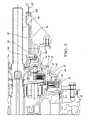
- FIG. 2is a fragmentary cross-sectional view of a portion of the transmission of FIG. 1 illustrating a drive unit extension connected to the rear housing;
- FIG. 3is a schematic perspective illustration in partial phantom, and partial cross-sectional view of the rear housing of FIGS. 1 and 2 ;
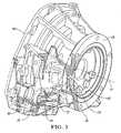
- FIG. 4is a fragmentary perspective view of an inner side of the rear housing of FIGS. 1-3 .
- FIG. 1shows a hybrid electromechanical transmission 10 with a center axis 12 .
- First and second electric motor/generators modules 14 , 16are disposed about the center axis 12 within the transmission 10 .
- Each of the motor/generator modules 14 , 16includes a respective rotor 17 A, 17 B, a respective stator 18 A, 18 B, and a motor housing 19 A, 19 B (each rotor and stator pair is an electric motor/generator).
- the electric motor/generator modules 14 , 16(labeled A and B) can be combined in various modes to accelerate and move a vehicle, to start an engine connected to the transmission, to brake the vehicle, and to charge batteries connected to the modules 14 , 16 .
- a main shaft 20is longitudinally disposed, rotatable about the center axis 12 .
- Several inner shaftssuch as inner shaft 22 , are concentrically disposed about the main shaft 20 , and are likewise rotatable about the center axis 12 .
- An input shaft 24is disposed forward of the main shaft 20 and is operable for transferring power from an engine (not shown) to the transmission 10 .
- Engagement of one or more of a plurality of clutches included in the transmission 10(first, second, third and fourth clutches, 26 , 28 , 30 and 32 respectively, being shown) interconnects one or more of first, second and third planetary gear sets 34 , 36 , and 38 , respectively, to transfer power at varying ratios to an output member 39 .
- a main casing or housing 40generally surrounds the motor/generator modules 14 , 16 as well as clutches 26 , 28 and planetary gear sets 34 , 36 .
- the arrangement of the two motors modules 14 , 16 in the transmission 10requires terminating the main housing 40 immediately aft of the more rearward motor 16 . This is necessary in order to permit installation of the two motor/generator modules 14 , 16 from opposing openings in the main housing. Referring also to FIGS.
- a rear housing 42mounts to the transmission main housing 40 at a front end 43 of the rear housing 42 to encase much of the transmission functionality, including a park pawl engagement gear 44 of a park pawl system (other components in the park pawl system such as an actuator not shown), the third and fourth clutches 30 , 32 , and the third planetary gear set 38 .
- Transmission lubrication fluidis present at the aft end of the transmission in residual from the third clutch piston 46 and the fourth clutch piston 48 , from the third clutch pack 50 and the fourth clutch pack 52 , and from support bushings 54 A, 54 B and thrust bearing 56 lubrication fluid.
- a drive unit extension 58is bolted to the rearward end 59 (shown in FIG.
- the drive unit extension 58is a housing component that houses the output member 39 and is configured to interact with additional drive line structure (not shown) to transmit power to vehicle wheels (not shown) as is well understood by those skilled in the art.
- a well 60is formed between the rear housing 42 and the drive unit extension 58 .
- a moderate amount of residual cooling fluidis desirable for lubricating support bushing 54 B (which is a driveline shaft bushing) and a transmission output seal 62 that are connected to drive unit extension 58 to pilot and seal the drive unit extension 58 to additional drive unit structure (not shown) that is splined to the output member 39 to complete the transmission driveline.
- a two-wheel drive adaptationis pictured, but the invention applies equally to a four-wheel drive adaptation.
- a method of returning the residual lubrication fluidis required. Since the clutches 30 , 32 and planetary gear set 38 packaged at the aft end of the transmission 10 do not allow direct return of the residual lubricating fluid (i.e., via an angle drilled passage) to a sump 64 , the rear housing 42 must provide a path for this fluid to the sump 64 .
- the residual fluid at the output seal 62is not in reasonable proximity to the sump 64 to use typical methods (such as angle drilling or sand cast cored passages) of returning spent lubrication fluid to the sump 64 .
- the rear housing 42includes a short axial passage or opening 70 (shown only in FIG. 3 ) parallel to the transmission center axis 12 to connect the well 60 at the output seal 62 to a cylindrical well 72 housing the park engagement gear 44 of FIG. 2 .
- a normal horizontal cross passage 74connects the bottom of the park engagement gear well 72 to the park engagement system access well 76 in the rear cover 42 .
- the park pawl engagement system well 76is sized to contain a park pawl actuator (not shown).
- the park pawl engagement system well 76is connected by a preferably cast relief second axial passage 80 to the sump 64 (see FIG. 2 ), bypassing the third and fourth clutches 36 , 38 , without requiring long angle drilled holes, or cast cored holes.
- FIG. 4shows a view looking rearward from inside of the rear housing 42 .
- the first axial passage 70 , the park engagement gear well 72 , the cross passage 74 , the park engagement system access well 76 and the second axial passage 80together create the fluid return path from the well 60 (see FIG. 2 ) to the main housing 40 .
- an additional benefit of this lube return systemis that the pooling of lubrication fluid 82 on the transmission output seal 62 may be set to optimal level L by location of the axial passage 70 connecting the output seal well 60 to the park pawl engagement gear well 72 .
- the angle drilled passagewould likely interrupt the park pawl engagement gear well 72 and the fourth piston bore 86 before exiting through a portion 88 of the rear housing 42 .
- Such a pathis not desirable as the fourth piston 48 will block drainage and the seam area at the edge of the rear housing 42 (near portion 88 of FIG. 4 ) will be compromised.
- this inventionmay reduce the number of rear housings rejected for leaks in comparison to housings having a long compound drilled hole typical for draining output well oil to sump. Associated costs including added leak testing, impregnation salvage rework, reinspection, and additional scrap may also be reduced.
- a method of returning fluid in a transmission 10 to a transmission sump 64includes casting a rear housing 42 .
- the methodalso provides drilling a generally axial passage 70 in the rear housing 42 and drilling another passage 74 generally perpendicular to the axial passage 70 .
- the rear housing 42is connected to the main housing 40 and a drive unit extension 58 is connected to the rear housing 42 to form a well 60 therebetween.
- output seal 62 and driveline shaft bushing 54 B in the drive unit extension 58are lubricated and fluid used to lubricate the output seal 62 and driveline shaft bushing 54 B is drained from the well 60 to an oil sump 64 through the passages 70 , 74 .
Landscapes
- Engineering & Computer Science (AREA)
- Chemical & Material Sciences (AREA)
- Combustion & Propulsion (AREA)
- Transportation (AREA)
- Mechanical Engineering (AREA)
- General Details Of Gearings (AREA)
Abstract
Description
Claims (16)
Priority Applications (2)
| Application Number | Priority Date | Filing Date | Title |
|---|---|---|---|
| US11/060,225US7276006B2 (en) | 2004-03-22 | 2005-02-17 | Transmission case for lube return and method |
| DE102005011862ADE102005011862B4 (en) | 2004-03-22 | 2005-03-15 | Transmission housing for lubricating oil return and method for this |
Applications Claiming Priority (2)
| Application Number | Priority Date | Filing Date | Title |
|---|---|---|---|
| US55514104P | 2004-03-22 | 2004-03-22 | |
| US11/060,225US7276006B2 (en) | 2004-03-22 | 2005-02-17 | Transmission case for lube return and method |
Publications (2)
| Publication Number | Publication Date |
|---|---|
| US20050204861A1 US20050204861A1 (en) | 2005-09-22 |
| US7276006B2true US7276006B2 (en) | 2007-10-02 |
Family
ID=34984768
Family Applications (1)
| Application Number | Title | Priority Date | Filing Date |
|---|---|---|---|
| US11/060,225Expired - Fee RelatedUS7276006B2 (en) | 2004-03-22 | 2005-02-17 | Transmission case for lube return and method |
Country Status (2)
| Country | Link |
|---|---|
| US (1) | US7276006B2 (en) |
| DE (1) | DE102005011862B4 (en) |
Cited By (34)
| Publication number | Priority date | Publication date | Assignee | Title |
|---|---|---|---|---|
| US20070011422A1 (en)* | 2005-07-11 | 2007-01-11 | General Electric Company | Hierarchical state based migration of structured data |
| US20100263965A1 (en)* | 2007-05-24 | 2010-10-21 | Fev Motorentechnik Gmbh | Oil supply and discharge for a transmission |
| US20110247454A1 (en)* | 2010-04-07 | 2011-10-13 | Gm Global Technology Operations, Inc. | Evacuated transmission case |
| US20110298318A1 (en)* | 2010-06-08 | 2011-12-08 | Bradfield Michael D | Gravity Fed Oil Cooling for an Electric Machine |
| US20110298316A1 (en)* | 2010-06-08 | 2011-12-08 | Bradfield Michael D | Electric Machine Cooling System and Method |
| US8395287B2 (en) | 2010-10-04 | 2013-03-12 | Remy Technologies, Llc | Coolant channels for electric machine stator |
| US8446056B2 (en) | 2010-09-29 | 2013-05-21 | Remy Technologies, Llc | Electric machine cooling system and method |
| US8482169B2 (en) | 2010-06-14 | 2013-07-09 | Remy Technologies, Llc | Electric machine cooling system and method |
| US8492952B2 (en) | 2010-10-04 | 2013-07-23 | Remy Technologies, Llc | Coolant channels for electric machine stator |
| US8497608B2 (en) | 2011-01-28 | 2013-07-30 | Remy Technologies, Llc | Electric machine cooling system and method |
| US8508085B2 (en) | 2010-10-04 | 2013-08-13 | Remy Technologies, Llc | Internal cooling of stator assembly in an electric machine |
| US8513840B2 (en) | 2010-05-04 | 2013-08-20 | Remy Technologies, Llc | Electric machine cooling system and method |
| US8519581B2 (en) | 2010-06-08 | 2013-08-27 | Remy Technologies, Llc | Electric machine cooling system and method |
| US8546983B2 (en) | 2010-10-14 | 2013-10-01 | Remy Technologies, Llc | Split drain system and method for an electric machine module |
| US8546982B2 (en) | 2011-07-12 | 2013-10-01 | Remy Technologies, Llc | Electric machine module cooling system and method |
| US8552600B2 (en) | 2010-06-14 | 2013-10-08 | Remy Technologies, Llc | Potted end turns of an electric machine |
| US8593021B2 (en) | 2010-10-04 | 2013-11-26 | Remy Technologies, Llc | Coolant drainage system and method for electric machines |
| US8614538B2 (en) | 2010-06-14 | 2013-12-24 | Remy Technologies, Llc | Electric machine cooling system and method |
| US8624452B2 (en) | 2011-04-18 | 2014-01-07 | Remy Technologies, Llc | Electric machine module cooling system and method |
| US8648506B2 (en) | 2010-11-09 | 2014-02-11 | Remy Technologies, Llc | Rotor lamination cooling system and method |
| US8659190B2 (en) | 2010-06-08 | 2014-02-25 | Remy Technologies, Llc | Electric machine cooling system and method |
| US8659191B2 (en) | 2010-05-18 | 2014-02-25 | Remy Technologies, Llc | Sleeve member for an electric machine |
| US8692425B2 (en) | 2011-05-10 | 2014-04-08 | Remy Technologies, Llc | Cooling combinations for electric machines |
| US8803381B2 (en) | 2011-07-11 | 2014-08-12 | Remy Technologies, Llc | Electric machine with cooling pipe coiled around stator assembly |
| US8803380B2 (en) | 2011-06-03 | 2014-08-12 | Remy Technologies, Llc | Electric machine module cooling system and method |
| US8901789B2 (en) | 2011-10-07 | 2014-12-02 | Remy Technologies, Llc | Electric machine module |
| US8975792B2 (en) | 2011-09-13 | 2015-03-10 | Remy Technologies, Llc | Electric machine module cooling system and method |
| US9041260B2 (en) | 2011-07-08 | 2015-05-26 | Remy Technologies, Llc | Cooling system and method for an electronic machine |
| US9048710B2 (en) | 2011-08-29 | 2015-06-02 | Remy Technologies, Llc | Electric machine module cooling system and method |
| US9054565B2 (en) | 2010-06-04 | 2015-06-09 | Remy Technologies, Llc | Electric machine cooling system and method |
| US9099900B2 (en) | 2011-12-06 | 2015-08-04 | Remy Technologies, Llc | Electric machine module cooling system and method |
| US9331543B2 (en) | 2012-04-05 | 2016-05-03 | Remy Technologies, Llc | Electric machine module cooling system and method |
| US10069375B2 (en) | 2012-05-02 | 2018-09-04 | Borgwarner Inc. | Electric machine module cooling system and method |
| US10208850B1 (en) | 2018-02-12 | 2019-02-19 | Ford Global Technologies, Llc | Transmission case with integrated drain channel |
Families Citing this family (12)
| Publication number | Priority date | Publication date | Assignee | Title |
|---|---|---|---|---|
| JP4259494B2 (en)* | 2005-03-04 | 2009-04-30 | トヨタ自動車株式会社 | Control device for vehicle drive device |
| JP4244944B2 (en)* | 2005-03-16 | 2009-03-25 | トヨタ自動車株式会社 | Control device for vehicle drive device |
| JP4244966B2 (en)* | 2005-06-22 | 2009-03-25 | トヨタ自動車株式会社 | Control device for vehicle drive device |
| US7670258B2 (en)* | 2006-06-15 | 2010-03-02 | Toyota Jidosha Kabushiki Kaisha | Control device for vehicle drive apparatus |
| JP4998164B2 (en)* | 2007-09-14 | 2012-08-15 | トヨタ自動車株式会社 | Control device for vehicle power transmission device |
| DE102009058734B4 (en)* | 2008-12-24 | 2013-07-18 | GM Global Technology Operations LLC (n. d. Ges. d. Staates Delaware) | Coupling assembly with double housing for a hybrid vehicle |
| DE102009058732B4 (en)* | 2008-12-24 | 2015-05-28 | GM Global Technology Operations LLC (n. d. Ges. d. Staates Delaware) | hybrid vehicle |
| JP2018162873A (en)* | 2017-03-27 | 2018-10-18 | アイシン・エーアイ株式会社 | transmission |
| JP6851431B2 (en)* | 2019-06-28 | 2021-03-31 | 本田技研工業株式会社 | Vehicle cooling structure |
| CN113154020B (en)* | 2021-04-29 | 2023-01-24 | 东风商用车有限公司 | Gearbox rear shell integrated with inner oil duct |
| CN113525066B (en)* | 2021-07-15 | 2022-11-01 | 东风汽车集团股份有限公司 | Hybrid drive system's casing and vehicle |
| KR102595942B1 (en) | 2021-11-25 | 2023-10-31 | 주식회사 카펙발레오 | A tortional damper and a hybrid drive module using the same |
Citations (8)
| Publication number | Priority date | Publication date | Assignee | Title |
|---|---|---|---|---|
| US2984122A (en)* | 1958-05-27 | 1961-05-16 | Borg Warner | Transmission mechanism |
| US4329887A (en)* | 1979-02-07 | 1982-05-18 | Nissan Motor Co., Ltd. | Transmission for an automobile |
| US5372213A (en)* | 1991-10-24 | 1994-12-13 | Aisin Aw Co., Ltd. | Oil circulating system for electric vehicle |
| US6227333B1 (en)* | 1999-06-24 | 2001-05-08 | Zf Meritor, Llc | Transmission housing with integral pump assembly |
| US6497211B2 (en) | 2000-10-13 | 2002-12-24 | Honda Giken Kogyo Kabushiki Kaisha | Lubrication structure of power unit |
| US6644440B2 (en)* | 2000-02-08 | 2003-11-11 | Honda Giken Kogyo Kabushiki Kaisha | Lubricating structure for output shaft bearing portion in transmission |
| US6729206B2 (en)* | 2000-08-11 | 2004-05-04 | Aisin Aw Co., Ltd. | Automatic transmission case |
| US7002267B2 (en)* | 2004-03-22 | 2006-02-21 | General Motors Corporation | Method and apparatus for cooling a hybrid transmission electric motor |
Family Cites Families (4)
| Publication number | Priority date | Publication date | Assignee | Title |
|---|---|---|---|---|
| DE6911180U (en)* | 1969-03-20 | 1969-10-02 | Opel Adam Ag | MOTOR VEHICLE TRANSMISSION WITH LUBRICATING DEVICE FOR ROTATING GEAR COMPONENTS. |
| US3618711A (en)* | 1970-06-08 | 1971-11-09 | Eaton Yale & Towne | Lubrication system for a geared-drive mechanism |
| DE3705607A1 (en)* | 1987-02-21 | 1988-09-01 | Porsche Ag | BEARING A AXLE DRIVE PINION |
| US6358173B1 (en)* | 2000-06-12 | 2002-03-19 | General Motors Corporation | Two-mode, compound-split, electro-mechanical vehicular transmission having significantly reduced vibrations |
- 2005
- 2005-02-17USUS11/060,225patent/US7276006B2/ennot_activeExpired - Fee Related
- 2005-03-15DEDE102005011862Apatent/DE102005011862B4/ennot_activeExpired - Fee Related
Patent Citations (8)
| Publication number | Priority date | Publication date | Assignee | Title |
|---|---|---|---|---|
| US2984122A (en)* | 1958-05-27 | 1961-05-16 | Borg Warner | Transmission mechanism |
| US4329887A (en)* | 1979-02-07 | 1982-05-18 | Nissan Motor Co., Ltd. | Transmission for an automobile |
| US5372213A (en)* | 1991-10-24 | 1994-12-13 | Aisin Aw Co., Ltd. | Oil circulating system for electric vehicle |
| US6227333B1 (en)* | 1999-06-24 | 2001-05-08 | Zf Meritor, Llc | Transmission housing with integral pump assembly |
| US6644440B2 (en)* | 2000-02-08 | 2003-11-11 | Honda Giken Kogyo Kabushiki Kaisha | Lubricating structure for output shaft bearing portion in transmission |
| US6729206B2 (en)* | 2000-08-11 | 2004-05-04 | Aisin Aw Co., Ltd. | Automatic transmission case |
| US6497211B2 (en) | 2000-10-13 | 2002-12-24 | Honda Giken Kogyo Kabushiki Kaisha | Lubrication structure of power unit |
| US7002267B2 (en)* | 2004-03-22 | 2006-02-21 | General Motors Corporation | Method and apparatus for cooling a hybrid transmission electric motor |
Cited By (37)
| Publication number | Priority date | Publication date | Assignee | Title |
|---|---|---|---|---|
| US20070011422A1 (en)* | 2005-07-11 | 2007-01-11 | General Electric Company | Hierarchical state based migration of structured data |
| US20100263965A1 (en)* | 2007-05-24 | 2010-10-21 | Fev Motorentechnik Gmbh | Oil supply and discharge for a transmission |
| US9032840B2 (en)* | 2010-04-07 | 2015-05-19 | Gm Global Technology Operations, Llc | Evacuated transmission case |
| US20110247454A1 (en)* | 2010-04-07 | 2011-10-13 | Gm Global Technology Operations, Inc. | Evacuated transmission case |
| US8513840B2 (en) | 2010-05-04 | 2013-08-20 | Remy Technologies, Llc | Electric machine cooling system and method |
| US8659191B2 (en) | 2010-05-18 | 2014-02-25 | Remy Technologies, Llc | Sleeve member for an electric machine |
| US9054565B2 (en) | 2010-06-04 | 2015-06-09 | Remy Technologies, Llc | Electric machine cooling system and method |
| US8456046B2 (en)* | 2010-06-08 | 2013-06-04 | Remy Technologies, Llc | Gravity fed oil cooling for an electric machine |
| US8269383B2 (en)* | 2010-06-08 | 2012-09-18 | Remy Technologies, Llc | Electric machine cooling system and method |
| US8659190B2 (en) | 2010-06-08 | 2014-02-25 | Remy Technologies, Llc | Electric machine cooling system and method |
| US20110298316A1 (en)* | 2010-06-08 | 2011-12-08 | Bradfield Michael D | Electric Machine Cooling System and Method |
| US8519581B2 (en) | 2010-06-08 | 2013-08-27 | Remy Technologies, Llc | Electric machine cooling system and method |
| US20110298318A1 (en)* | 2010-06-08 | 2011-12-08 | Bradfield Michael D | Gravity Fed Oil Cooling for an Electric Machine |
| US8552600B2 (en) | 2010-06-14 | 2013-10-08 | Remy Technologies, Llc | Potted end turns of an electric machine |
| US8482169B2 (en) | 2010-06-14 | 2013-07-09 | Remy Technologies, Llc | Electric machine cooling system and method |
| US8614538B2 (en) | 2010-06-14 | 2013-12-24 | Remy Technologies, Llc | Electric machine cooling system and method |
| US8446056B2 (en) | 2010-09-29 | 2013-05-21 | Remy Technologies, Llc | Electric machine cooling system and method |
| US8593021B2 (en) | 2010-10-04 | 2013-11-26 | Remy Technologies, Llc | Coolant drainage system and method for electric machines |
| US8492952B2 (en) | 2010-10-04 | 2013-07-23 | Remy Technologies, Llc | Coolant channels for electric machine stator |
| US8508085B2 (en) | 2010-10-04 | 2013-08-13 | Remy Technologies, Llc | Internal cooling of stator assembly in an electric machine |
| US8395287B2 (en) | 2010-10-04 | 2013-03-12 | Remy Technologies, Llc | Coolant channels for electric machine stator |
| US8546983B2 (en) | 2010-10-14 | 2013-10-01 | Remy Technologies, Llc | Split drain system and method for an electric machine module |
| US8648506B2 (en) | 2010-11-09 | 2014-02-11 | Remy Technologies, Llc | Rotor lamination cooling system and method |
| US8497608B2 (en) | 2011-01-28 | 2013-07-30 | Remy Technologies, Llc | Electric machine cooling system and method |
| US8624452B2 (en) | 2011-04-18 | 2014-01-07 | Remy Technologies, Llc | Electric machine module cooling system and method |
| US8692425B2 (en) | 2011-05-10 | 2014-04-08 | Remy Technologies, Llc | Cooling combinations for electric machines |
| US8803380B2 (en) | 2011-06-03 | 2014-08-12 | Remy Technologies, Llc | Electric machine module cooling system and method |
| US9041260B2 (en) | 2011-07-08 | 2015-05-26 | Remy Technologies, Llc | Cooling system and method for an electronic machine |
| US8803381B2 (en) | 2011-07-11 | 2014-08-12 | Remy Technologies, Llc | Electric machine with cooling pipe coiled around stator assembly |
| US8546982B2 (en) | 2011-07-12 | 2013-10-01 | Remy Technologies, Llc | Electric machine module cooling system and method |
| US9048710B2 (en) | 2011-08-29 | 2015-06-02 | Remy Technologies, Llc | Electric machine module cooling system and method |
| US8975792B2 (en) | 2011-09-13 | 2015-03-10 | Remy Technologies, Llc | Electric machine module cooling system and method |
| US8901789B2 (en) | 2011-10-07 | 2014-12-02 | Remy Technologies, Llc | Electric machine module |
| US9099900B2 (en) | 2011-12-06 | 2015-08-04 | Remy Technologies, Llc | Electric machine module cooling system and method |
| US9331543B2 (en) | 2012-04-05 | 2016-05-03 | Remy Technologies, Llc | Electric machine module cooling system and method |
| US10069375B2 (en) | 2012-05-02 | 2018-09-04 | Borgwarner Inc. | Electric machine module cooling system and method |
| US10208850B1 (en) | 2018-02-12 | 2019-02-19 | Ford Global Technologies, Llc | Transmission case with integrated drain channel |
Also Published As
| Publication number | Publication date |
|---|---|
| DE102005011862A1 (en) | 2005-11-10 |
| US20050204861A1 (en) | 2005-09-22 |
| DE102005011862B4 (en) | 2009-10-15 |
Similar Documents
| Publication | Publication Date | Title |
|---|---|---|
| US7276006B2 (en) | Transmission case for lube return and method | |
| CN100422598C (en) | Gearbox housing and method for lubricating oil return | |
| US8678784B2 (en) | Drive device | |
| EP3309429B1 (en) | Oil passage structure for power transmission device | |
| US10630140B2 (en) | Electric vehicle drive system | |
| US7508100B2 (en) | Electric motor/generator and method of cooling an electromechanical transmission | |
| US8851861B2 (en) | Powertrain hydraulic system for hybrid electric vehicles | |
| US7727099B2 (en) | Vehicle driving device | |
| US6863140B2 (en) | Motor vehicle drive arrangement | |
| US20080099258A1 (en) | Vented sealed housing assembly for vehicle powertrain | |
| US20150132163A1 (en) | Electric pump for a hybrid vehicle | |
| US12078238B2 (en) | Lubrication structure for vehicle | |
| US7421928B2 (en) | Motor vehicle drive arrangement | |
| JP5062040B2 (en) | Power transmission device | |
| WO2023006221A1 (en) | Electric drive for a vehicle | |
| WO2013054385A1 (en) | Power transmission device | |
| CN113472137B (en) | Driving device | |
| US7399247B2 (en) | Sun gear bushing and sleeve and method for sealing in a hybrid electromechanical automatic transmission | |
| JP4701587B2 (en) | Electric drive | |
| JP2016101879A (en) | Drive device for vehicle and assembly method of the same | |
| US7247112B2 (en) | Method and apparatus for cooling and lubricating a hybrid transmission | |
| CN115539612A (en) | Cooling and lubricating system, gearbox and automobile | |
| US20230065709A1 (en) | Drive apparatus | |
| WO2023006217A1 (en) | Electric drive for a motor vehicle | |
| CN119546882A (en) | Hybrid powertrain reduction gear |
Legal Events
| Date | Code | Title | Description |
|---|---|---|---|
| AS | Assignment | Owner name:GENERAL MOTORS CORPORATION, MICHIGAN Free format text:ASSIGNMENT OF ASSIGNORS INTEREST;ASSIGNORS:REED, WILLIAM S.;LOVE, BERT D.;REEL/FRAME:016033/0995;SIGNING DATES FROM 20050103 TO 20050301 | |
| STCF | Information on status: patent grant | Free format text:PATENTED CASE | |
| AS | Assignment | Owner name:GM GLOBAL TECHNOLOGY OPERATIONS, INC., MICHIGAN Free format text:ASSIGNMENT OF ASSIGNORS INTEREST;ASSIGNOR:GENERAL MOTORS CORPORATION;REEL/FRAME:022117/0001 Effective date:20050119 Owner name:GM GLOBAL TECHNOLOGY OPERATIONS, INC.,MICHIGAN Free format text:ASSIGNMENT OF ASSIGNORS INTEREST;ASSIGNOR:GENERAL MOTORS CORPORATION;REEL/FRAME:022117/0001 Effective date:20050119 | |
| AS | Assignment | Owner name:UNITED STATES DEPARTMENT OF THE TREASURY, DISTRICT Free format text:SECURITY AGREEMENT;ASSIGNOR:GM GLOBAL TECHNOLOGY OPERATIONS, INC.;REEL/FRAME:022201/0610 Effective date:20081231 Owner name:UNITED STATES DEPARTMENT OF THE TREASURY,DISTRICT Free format text:SECURITY AGREEMENT;ASSIGNOR:GM GLOBAL TECHNOLOGY OPERATIONS, INC.;REEL/FRAME:022201/0610 Effective date:20081231 | |
| AS | Assignment | Owner name:CITICORP USA, INC. AS AGENT FOR BANK PRIORITY SECU Free format text:SECURITY AGREEMENT;ASSIGNOR:GM GLOBAL TECHNOLOGY OPERATIONS, INC.;REEL/FRAME:022553/0446 Effective date:20090409 Owner name:CITICORP USA, INC. AS AGENT FOR HEDGE PRIORITY SEC Free format text:SECURITY AGREEMENT;ASSIGNOR:GM GLOBAL TECHNOLOGY OPERATIONS, INC.;REEL/FRAME:022553/0446 Effective date:20090409 | |
| AS | Assignment | Owner name:GM GLOBAL TECHNOLOGY OPERATIONS, INC., MICHIGAN Free format text:RELEASE BY SECURED PARTY;ASSIGNOR:UNITED STATES DEPARTMENT OF THE TREASURY;REEL/FRAME:023124/0429 Effective date:20090709 Owner name:GM GLOBAL TECHNOLOGY OPERATIONS, INC.,MICHIGAN Free format text:RELEASE BY SECURED PARTY;ASSIGNOR:UNITED STATES DEPARTMENT OF THE TREASURY;REEL/FRAME:023124/0429 Effective date:20090709 | |
| AS | Assignment | Owner name:GM GLOBAL TECHNOLOGY OPERATIONS, INC., MICHIGAN Free format text:RELEASE BY SECURED PARTY;ASSIGNORS:CITICORP USA, INC. AS AGENT FOR BANK PRIORITY SECURED PARTIES;CITICORP USA, INC. AS AGENT FOR HEDGE PRIORITY SECURED PARTIES;REEL/FRAME:023127/0468 Effective date:20090814 Owner name:GM GLOBAL TECHNOLOGY OPERATIONS, INC.,MICHIGAN Free format text:RELEASE BY SECURED PARTY;ASSIGNORS:CITICORP USA, INC. AS AGENT FOR BANK PRIORITY SECURED PARTIES;CITICORP USA, INC. AS AGENT FOR HEDGE PRIORITY SECURED PARTIES;REEL/FRAME:023127/0468 Effective date:20090814 | |
| AS | Assignment | Owner name:UNITED STATES DEPARTMENT OF THE TREASURY, DISTRICT Free format text:SECURITY AGREEMENT;ASSIGNOR:GM GLOBAL TECHNOLOGY OPERATIONS, INC.;REEL/FRAME:023156/0052 Effective date:20090710 Owner name:UNITED STATES DEPARTMENT OF THE TREASURY,DISTRICT Free format text:SECURITY AGREEMENT;ASSIGNOR:GM GLOBAL TECHNOLOGY OPERATIONS, INC.;REEL/FRAME:023156/0052 Effective date:20090710 | |
| AS | Assignment | Owner name:UAW RETIREE MEDICAL BENEFITS TRUST, MICHIGAN Free format text:SECURITY AGREEMENT;ASSIGNOR:GM GLOBAL TECHNOLOGY OPERATIONS, INC.;REEL/FRAME:023162/0001 Effective date:20090710 Owner name:UAW RETIREE MEDICAL BENEFITS TRUST,MICHIGAN Free format text:SECURITY AGREEMENT;ASSIGNOR:GM GLOBAL TECHNOLOGY OPERATIONS, INC.;REEL/FRAME:023162/0001 Effective date:20090710 | |
| AS | Assignment | Owner name:GM GLOBAL TECHNOLOGY OPERATIONS, INC., MICHIGAN Free format text:RELEASE BY SECURED PARTY;ASSIGNOR:UNITED STATES DEPARTMENT OF THE TREASURY;REEL/FRAME:025245/0442 Effective date:20100420 Owner name:GM GLOBAL TECHNOLOGY OPERATIONS, INC., MICHIGAN Free format text:RELEASE BY SECURED PARTY;ASSIGNOR:UAW RETIREE MEDICAL BENEFITS TRUST;REEL/FRAME:025311/0770 Effective date:20101026 | |
| AS | Assignment | Owner name:WILMINGTON TRUST COMPANY, DELAWARE Free format text:SECURITY AGREEMENT;ASSIGNOR:GM GLOBAL TECHNOLOGY OPERATIONS, INC.;REEL/FRAME:025327/0001 Effective date:20101027 | |
| AS | Assignment | Owner name:GM GLOBAL TECHNOLOGY OPERATIONS LLC, MICHIGAN Free format text:CHANGE OF NAME;ASSIGNOR:GM GLOBAL TECHNOLOGY OPERATIONS, INC.;REEL/FRAME:025780/0936 Effective date:20101202 | |
| FPAY | Fee payment | Year of fee payment:4 | |
| AS | Assignment | Owner name:GM GLOBAL TECHNOLOGY OPERATIONS LLC, MICHIGAN Free format text:RELEASE BY SECURED PARTY;ASSIGNOR:WILMINGTON TRUST COMPANY;REEL/FRAME:034371/0676 Effective date:20141017 | |
| FPAY | Fee payment | Year of fee payment:8 | |
| FEPP | Fee payment procedure | Free format text:MAINTENANCE FEE REMINDER MAILED (ORIGINAL EVENT CODE: REM.); ENTITY STATUS OF PATENT OWNER: LARGE ENTITY | |
| LAPS | Lapse for failure to pay maintenance fees | Free format text:PATENT EXPIRED FOR FAILURE TO PAY MAINTENANCE FEES (ORIGINAL EVENT CODE: EXP.); ENTITY STATUS OF PATENT OWNER: LARGE ENTITY | |
| STCH | Information on status: patent discontinuation | Free format text:PATENT EXPIRED DUE TO NONPAYMENT OF MAINTENANCE FEES UNDER 37 CFR 1.362 | |
| FP | Lapsed due to failure to pay maintenance fee | Effective date:20191002 |