US7275646B2 - Apparatus and method for adapting two-post rack systems to support four-post rack mounted equipment - Google Patents
Apparatus and method for adapting two-post rack systems to support four-post rack mounted equipmentDownload PDFInfo
- Publication number
- US7275646B2 US7275646B2US10/008,766US876601AUS7275646B2US 7275646 B2US7275646 B2US 7275646B2US 876601 AUS876601 AUS 876601AUS 7275646 B2US7275646 B2US 7275646B2
- Authority
- US
- United States
- Prior art keywords
- post
- coupling member
- rack
- equipment
- coupling
- Prior art date
- Legal status (The legal status is an assumption and is not a legal conclusion. Google has not performed a legal analysis and makes no representation as to the accuracy of the status listed.)
- Expired - Lifetime, expires
Links
- 238000000034methodMethods0.000titleabstractdescription11
- 230000008878couplingEffects0.000claimsabstractdescription191
- 238000010168coupling processMethods0.000claimsabstractdescription191
- 238000005859coupling reactionMethods0.000claimsabstractdescription191
- 238000012546transferMethods0.000claimsabstractdescription6
- 230000001154acute effectEffects0.000claimsdescription5
- 238000009423ventilationMethods0.000claimsdescription2
- 230000008901benefitEffects0.000description7
- 230000000712assemblyEffects0.000description6
- 238000000429assemblyMethods0.000description6
- 239000002184metalSubstances0.000description5
- 230000003362replicative effectEffects0.000description5
- 238000013461designMethods0.000description4
- 238000009434installationMethods0.000description4
- 230000008569processEffects0.000description3
- 238000004364calculation methodMethods0.000description2
- 238000006243chemical reactionMethods0.000description2
- 238000012986modificationMethods0.000description2
- 230000004048modificationEffects0.000description2
- 238000003491arrayMethods0.000description1
- 238000005266castingMethods0.000description1
- 238000010276constructionMethods0.000description1
- 238000001816coolingMethods0.000description1
- 238000012937correctionMethods0.000description1
- 238000002788crimpingMethods0.000description1
- 230000000694effectsEffects0.000description1
- 238000001125extrusionMethods0.000description1
- 230000007246mechanismEffects0.000description1
- 239000007769metal materialSubstances0.000description1
- 229910052755nonmetalInorganic materials0.000description1
- 238000010422paintingMethods0.000description1
- 230000000750progressive effectEffects0.000description1
- 239000013585weight reducing agentSubstances0.000description1
Images


Classifications
- H—ELECTRICITY
- H05—ELECTRIC TECHNIQUES NOT OTHERWISE PROVIDED FOR
- H05K—PRINTED CIRCUITS; CASINGS OR CONSTRUCTIONAL DETAILS OF ELECTRIC APPARATUS; MANUFACTURE OF ASSEMBLAGES OF ELECTRICAL COMPONENTS
- H05K7/00—Constructional details common to different types of electric apparatus
- H05K7/18—Construction of rack or frame
- H05K7/186—Construction of rack or frame for supporting telecommunication equipment
- Y—GENERAL TAGGING OF NEW TECHNOLOGICAL DEVELOPMENTS; GENERAL TAGGING OF CROSS-SECTIONAL TECHNOLOGIES SPANNING OVER SEVERAL SECTIONS OF THE IPC; TECHNICAL SUBJECTS COVERED BY FORMER USPC CROSS-REFERENCE ART COLLECTIONS [XRACs] AND DIGESTS
- Y10—TECHNICAL SUBJECTS COVERED BY FORMER USPC
- Y10T—TECHNICAL SUBJECTS COVERED BY FORMER US CLASSIFICATION
- Y10T29/00—Metal working
- Y10T29/49—Method of mechanical manufacture
- Y10T29/49716—Converting
- Y—GENERAL TAGGING OF NEW TECHNOLOGICAL DEVELOPMENTS; GENERAL TAGGING OF CROSS-SECTIONAL TECHNOLOGIES SPANNING OVER SEVERAL SECTIONS OF THE IPC; TECHNICAL SUBJECTS COVERED BY FORMER USPC CROSS-REFERENCE ART COLLECTIONS [XRACs] AND DIGESTS
- Y10—TECHNICAL SUBJECTS COVERED BY FORMER USPC
- Y10T—TECHNICAL SUBJECTS COVERED BY FORMER US CLASSIFICATION
- Y10T403/00—Joints and connections
- Y10T403/33—Transverse rod to spaced plate surfaces
- Y—GENERAL TAGGING OF NEW TECHNOLOGICAL DEVELOPMENTS; GENERAL TAGGING OF CROSS-SECTIONAL TECHNOLOGIES SPANNING OVER SEVERAL SECTIONS OF THE IPC; TECHNICAL SUBJECTS COVERED BY FORMER USPC CROSS-REFERENCE ART COLLECTIONS [XRACs] AND DIGESTS
- Y10—TECHNICAL SUBJECTS COVERED BY FORMER USPC
- Y10T—TECHNICAL SUBJECTS COVERED BY FORMER US CLASSIFICATION
- Y10T403/00—Joints and connections
- Y10T403/71—Rod side to plate or side
Definitions
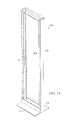
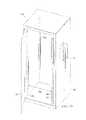
- Equipment racksare used to support many different types of equipment or systems (e.g., computer servers). Many equipment manufacturers provide equipment with support mechanisms for being supported in traditional four-post rack systems (e.g., cabinets). Often, four-post racks, such as those shown in (Electronic Industries Association) EIA Standard EIA-310-D, incorporated herein by reference, can cost thousands of dollars while two-post equipment racks may only cost several hundred dollars. Therefore, users of four-post rack mountable equipment are interested in an economical, easy alternative to having to use four-post rack systems.
- FIGS. 8A-8Eare side views of exemplary embodiments according to the principles of the present invention.
- FIG. 10is an exemplary perspective side view of two coupling members coupled together
- FIG. 13is an exemplary flow chart for providing a two- to four-post adapter according to the principles of the present invention.
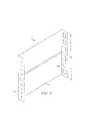
- FIG. 2Athere is shown a perspective view of a coupling member 10 A in an alternate embodiment, with like numerals being designated for like parts.
- This embodimentis similar to coupling member 10 of FIG. 1 .
- the vertical support member 20 Ais not provided with any openings.
- This embodimentsupports loads in a similar fashion as the coupling member 10 of FIG. 1 .
- the thickness of the vertical support member 20 A, and the flanges 130 A, 140 Amay be adjusted to compensate for the loss of the first torsion member 70 and the second torsion member 80 in the embodiment of FIG. 1 .
- the height Z of the flange 130 Amay be adjusted to compensate for the loss of the lower flange end adapted to act as a pivot point in the embodiment of FIG. 1 .
Landscapes
- Engineering & Computer Science (AREA)
- Microelectronics & Electronic Packaging (AREA)
- Cooling Or The Like Of Electrical Apparatus (AREA)
- Casings For Electric Apparatus (AREA)
- Assembled Shelves (AREA)
Abstract
Description
Claims (28)
Priority Applications (2)
| Application Number | Priority Date | Filing Date | Title |
|---|---|---|---|
| US10/008,766US7275646B2 (en) | 2000-11-07 | 2001-11-07 | Apparatus and method for adapting two-post rack systems to support four-post rack mounted equipment |
| US11/845,681US7591056B2 (en) | 2000-11-07 | 2007-08-27 | Method for adapting two-post rack systems to support four-post rack mounted equipment |
Applications Claiming Priority (2)
| Application Number | Priority Date | Filing Date | Title |
|---|---|---|---|
| US24702100P | 2000-11-07 | 2000-11-07 | |
| US10/008,766US7275646B2 (en) | 2000-11-07 | 2001-11-07 | Apparatus and method for adapting two-post rack systems to support four-post rack mounted equipment |
Related Child Applications (1)
| Application Number | Title | Priority Date | Filing Date |
|---|---|---|---|
| US11/845,681DivisionUS7591056B2 (en) | 2000-11-07 | 2007-08-27 | Method for adapting two-post rack systems to support four-post rack mounted equipment |
Publications (2)
| Publication Number | Publication Date |
|---|---|
| US20020104942A1 US20020104942A1 (en) | 2002-08-08 |
| US7275646B2true US7275646B2 (en) | 2007-10-02 |
Family
ID=26678596
Family Applications (2)
| Application Number | Title | Priority Date | Filing Date |
|---|---|---|---|
| US10/008,766Expired - LifetimeUS7275646B2 (en) | 2000-11-07 | 2001-11-07 | Apparatus and method for adapting two-post rack systems to support four-post rack mounted equipment |
| US11/845,681Expired - LifetimeUS7591056B2 (en) | 2000-11-07 | 2007-08-27 | Method for adapting two-post rack systems to support four-post rack mounted equipment |
Family Applications After (1)
| Application Number | Title | Priority Date | Filing Date |
|---|---|---|---|
| US11/845,681Expired - LifetimeUS7591056B2 (en) | 2000-11-07 | 2007-08-27 | Method for adapting two-post rack systems to support four-post rack mounted equipment |
Country Status (1)
| Country | Link |
|---|---|
| US (2) | US7275646B2 (en) |
Cited By (23)
| Publication number | Priority date | Publication date | Assignee | Title |
|---|---|---|---|---|
| US20060180555A1 (en)* | 2005-02-05 | 2006-08-17 | Asustek Computer Inc. | Rack bracket structure |
| US20070131628A1 (en)* | 2002-03-14 | 2007-06-14 | Innovation First, Inc. A Texas Corporation | Universal rack-mountable shelf |
| US20070227992A1 (en)* | 2002-07-18 | 2007-10-04 | Innovation First, Inc., A Texas Corporation | Sliding Rack-Mountable Shelf for Rack-Mountable Components |
| US20080143225A1 (en)* | 2006-12-18 | 2008-06-19 | Hirsh Industries, Inc. | Cabinet drawer and stationary drawer glide |
| US20120043869A1 (en)* | 2010-08-18 | 2012-02-23 | Hon Hai Precision Industry Co., Ltd. | Server rack |
| US20120091075A1 (en)* | 2008-03-28 | 2012-04-19 | Zonit Structured Solutions, Llc | Uniform equipment mounting system |
| US20120104200A1 (en)* | 2010-10-29 | 2012-05-03 | International Business Machines Corporation | Self-supporting cantilevered mounting system and methods of installation thereof |
| US8570743B2 (en)* | 2012-03-08 | 2013-10-29 | Hong Fu Jin Precision Industry (Shenzhen) Co., Ltd. | Mounting apparatus for fans |
| US8925739B2 (en)* | 2012-07-26 | 2015-01-06 | Lenovo Enterprise Solutions (Singapore) Pte. Ltd. | High-capacity computer rack with rear-accessible side bays |
| US20160338217A1 (en)* | 2015-05-15 | 2016-11-17 | Innovation First, Inc. | Connectors To Secure Multiple Rails In A Server Rack |
| US9895623B2 (en) | 2011-10-13 | 2018-02-20 | Building Creative Kids, Llc | Toy couplers including a plurality of block retaining channels |
| USD846971S1 (en)* | 2015-09-25 | 2019-04-30 | Innovation First, Inc. | Rail for use in a server equipment rack |
| US20190132986A1 (en)* | 2017-10-31 | 2019-05-02 | King Slide Works Co., Ltd. | Slide rail mechanism |
| US10398999B2 (en) | 2011-10-13 | 2019-09-03 | Building Creative Kids, Llc | Toy couplers including a plurality of block retaining channels |
| US10493371B2 (en) | 2015-01-06 | 2019-12-03 | Building Creative Kids, Llc | Toy building systems including adjustable connector clips, building planks, and panels |
| USD877263S1 (en) | 2011-10-13 | 2020-03-03 | Building Creative Kids, Llc | Toy coupler |
| USD926024S1 (en)* | 2018-04-19 | 2021-07-27 | Goldfinch Brothers Inc. | Sliding door top rail |
| US20220125198A1 (en)* | 2019-02-04 | 2022-04-28 | Vodafone Ip Licensing Limited | Rack installation support |
| US20220381051A1 (en)* | 2021-05-25 | 2022-12-01 | Vertiv Corporation | Outdoor seismic equipment enclosures |
| US11690451B2 (en) | 2021-03-10 | 2023-07-04 | King Slide Works Co., Ltd. | Slide rail mechanism and slide rail kit thereof |
| USD1023007S1 (en)* | 2021-04-09 | 2024-04-16 | Chenbro Micom Co., Ltd. | Casing support member |
| USD1033436S1 (en)* | 2021-06-04 | 2024-07-02 | Chenbro Micom Co., Ltd. | Fan module cover |
| US20240244780A1 (en)* | 2021-05-19 | 2024-07-18 | Hitachi Astemo, Ltd. | Electronic control device |
Families Citing this family (45)
| Publication number | Priority date | Publication date | Assignee | Title |
|---|---|---|---|---|
| US6988626B2 (en)* | 1998-07-31 | 2006-01-24 | Varghese Paily T | Computer component rack mounting arrangement |
| US6976745B2 (en)* | 2001-09-19 | 2005-12-20 | Hewlett-Packard Development Company, L.P. | Snap-on slide and rail assembly |
| US6702412B2 (en) | 2001-09-19 | 2004-03-09 | Hewlett-Packard Development Company, L.P. | Expandable slide and rail assembly for a rack and method of installing same |
| US7012808B2 (en)* | 2002-12-20 | 2006-03-14 | Hewlett-Packard Development Company, L.P. | Multi-configurable telecommunications rack mounting system and method incorporating same |
| US7137512B2 (en) | 2003-02-19 | 2006-11-21 | Hewlett-Packard Development Company, L.P. | Removable rails for use on racks |
| US20040217073A1 (en)* | 2003-05-01 | 2004-11-04 | Dobler Karl J. | System and method for utilizing a tool-less rail in a rack |
| DE102004059408B4 (en)* | 2004-12-09 | 2007-07-19 | Knürr AG | frame |
| US20070175836A1 (en)* | 2006-01-27 | 2007-08-02 | Gerhard Bumeder | Frame structure |
| US9198324B1 (en) | 2006-02-28 | 2015-11-24 | Gorgius L. Yousif | Modular mount rack frame |
| US7520474B1 (en)* | 2006-04-28 | 2009-04-21 | Sioux Chief Mfg. Co., Inc. | Cantilevered pipe support bracket |
| US7455266B2 (en)* | 2006-09-15 | 2008-11-25 | Faircloth Franklin J | Electrical conduit support apparatus |
| US20100032538A1 (en)* | 2008-08-11 | 2010-02-11 | Arnold Keith D | Electrical device hanger |
| JP4745427B2 (en)* | 2009-07-14 | 2011-08-10 | 富士通株式会社 | Article holding device and rack device provided with the same |
| CN101954328B (en)* | 2009-07-14 | 2013-08-28 | 鸿富锦精密工业(深圳)有限公司 | Three-dimensional printing device |
| US8833711B2 (en)* | 2010-04-27 | 2014-09-16 | Panduit Corp. | Two post rack with floor mounting brackets |
| CN101915344B (en)* | 2010-07-13 | 2013-05-22 | 乐克斯瑞(北京)数字技术有限公司 | Assembled digital home terminal with design of independent functional components |
| US20120080395A1 (en)* | 2010-09-30 | 2012-04-05 | King Slide Works Co., Ltd. | Positioning device used on rack |
| US8582299B1 (en) | 2010-12-23 | 2013-11-12 | Amazon Technologies, Inc. | System with movable computing devices |
| US10025357B2 (en)* | 2015-06-15 | 2018-07-17 | Seagate Technology Llc | Enclosure system for computing equipment |
| US10371291B2 (en)* | 2016-07-18 | 2019-08-06 | Johnson Controls Technology Company | Valve package supports and method of manufacture |
| US10034407B2 (en) | 2016-07-22 | 2018-07-24 | Intel Corporation | Storage sled for a data center |
| US10499535B2 (en) | 2016-08-03 | 2019-12-03 | Schneider Electric It Corporation | Modular rack system |
| US20190269964A1 (en)* | 2018-03-05 | 2019-09-05 | Charles Huthmaker | Concept2 Ergometer End Cap Adapter |
| USD1032597S1 (en)* | 2021-02-11 | 2024-06-25 | Rackmount International B.V. | Rack mount kit for desktop network appliances |
| USD1033418S1 (en)* | 2021-02-11 | 2024-07-02 | Rackmount International B.V. | Rack mount kit for desktop network appliances |
| USD1072804S1 (en)* | 2021-02-11 | 2025-04-29 | Rackmount.IT B.V. | Rack mount kit for desktop network appliances |
| USD1032616S1 (en)* | 2021-02-11 | 2024-06-25 | Rackmount International B.V. | Rack mount kit for desktop network appliances |
| USD1009040S1 (en)* | 2021-05-14 | 2023-12-26 | Rackmount International B.V. | Rack mount kit for desktop network appliances |
| USD1008245S1 (en)* | 2021-05-14 | 2023-12-19 | Rackmount International B.V. | Rack mount kit for desktop network appliances |
| USD1009024S1 (en)* | 2021-05-14 | 2023-12-26 | Rackmount International B.V. | Rack mount kit for desktop network appliances |
| USD1008275S1 (en)* | 2021-05-14 | 2023-12-19 | Rackmount International B.V. | Rack mount kit for desktop network appliances |
| USD1029821S1 (en)* | 2021-05-14 | 2024-06-04 | Rackmount International B.V. | Rack mount kit for desktop network appliances |
| USD1008244S1 (en)* | 2021-05-14 | 2023-12-19 | Rackmount International B.V. | Rack mount kit for desktop network appliances |
| USD1008248S1 (en)* | 2021-05-14 | 2023-12-19 | Rackmount International B.V. | Rack mount kit for desktop network appliances |
| USD1008247S1 (en)* | 2021-05-14 | 2023-12-19 | Rackmount International B.V. | Rack mount kit for desktop network appliances |
| USD1009021S1 (en)* | 2021-05-14 | 2023-12-26 | Rackmount International B.V. | Rack mount kit for desktop network appliances |
| USD1008249S1 (en)* | 2021-05-14 | 2023-12-19 | Rackmount International B.V. | Rack mount kit for desktop network appliances |
| USD1008243S1 (en)* | 2021-05-14 | 2023-12-19 | Rackmount International B.V. | Rack mount kit for desktop network appliances |
| USD1008246S1 (en)* | 2021-05-14 | 2023-12-19 | Rackmount International B.V. | Rack mount kit for desktop network appliances |
| USD1009022S1 (en)* | 2021-05-14 | 2023-12-26 | Rackmount International B.V. | Rack mount kit for desktop network appliances |
| USD1008250S1 (en)* | 2021-05-14 | 2023-12-19 | Rackmount International B.V. | Rack mount kit for desktop network appliances |
| USD1009023S1 (en)* | 2021-05-14 | 2023-12-26 | Rackmount International B.V. | Rack mount kit for desktop network appliances |
| US12181172B2 (en)* | 2021-08-05 | 2024-12-31 | Johnson Controls Tyco IP Holdings LLP | Support assembly for HVAC system |
| USD1041292S1 (en)* | 2021-12-09 | 2024-09-10 | CFW Investments LLC | Cable organizer |
| USD1011340S1 (en)* | 2022-10-18 | 2024-01-16 | Rackmount International B.V. | Rack mount kit for desktop network appliances |
Citations (28)
| Publication number | Priority date | Publication date | Assignee | Title |
|---|---|---|---|---|
| US5215362A (en) | 1991-07-30 | 1993-06-01 | United Technologies Automotive, Inc. | Modular file kit and assembly |
| US5340340A (en) | 1992-09-24 | 1994-08-23 | Compaq Computer Corporation | Apparatus for removably supporting a plurality of hot plug-connected hard disk drives |
| US5351176A (en) | 1992-12-31 | 1994-09-27 | North Atlantic Industries, Inc. | Panel for a computer including a hinged door with integral display |
| US5542549A (en)* | 1994-11-22 | 1996-08-06 | The Siemon Company | Cross connect frame for communication connector blocks and other devices |
| US5873641A (en) | 1996-02-16 | 1999-02-23 | Spinelli; Larry | Food case liner |
| US5941621A (en)* | 1997-02-28 | 1999-08-24 | Digital Equipment Corporation | Cabinet slide mounting bracket |
| US6021909A (en) | 1998-11-13 | 2000-02-08 | Hewlett-Packard Company | Equipment enclosure rack support rail system |
| US6142590A (en) | 1999-04-05 | 2000-11-07 | Central Industrial Supply Company | Two U vertical height keyboard and flatscreen drawer for a server system rack |
| US6170784B1 (en) | 1998-06-18 | 2001-01-09 | Polygon Wire Management, Inc. | Cable management device |
| US6201690B1 (en) | 1998-09-01 | 2001-03-13 | Emc Corporation | Rack console assembly |
| US6220456B1 (en)* | 2000-04-19 | 2001-04-24 | Dell Products, L.P. | Method and apparatus for supporting a computer chassis |
| US6227630B1 (en) | 1998-04-08 | 2001-05-08 | International Business Machines Corporation | Accessory mounting for digital computer |
| US6254041B1 (en) | 1998-08-03 | 2001-07-03 | Societe De Constructions Eleciriques De La Seine (Ces) | Cable conduit |
| US20010040142A1 (en)* | 1999-10-27 | 2001-11-15 | Gerome A. Haney | Vertical locating slide bracket |
| US6349837B1 (en) | 1999-11-10 | 2002-02-26 | Marconi Communications, Inc. | Stiffened relay rack |
| US6370022B1 (en) | 1999-07-13 | 2002-04-09 | Gateway, Inc. | Screwless computer drive assembly |
| US20020043508A1 (en) | 2000-10-13 | 2002-04-18 | Lewis Kevin William | Support bracket |
| US6431668B1 (en)* | 1998-02-19 | 2002-08-13 | Edward Arnold Reddicliffe | Method of installing a telescopic shelf in a cabinet |
| US6442020B1 (en) | 2000-03-09 | 2002-08-27 | Hon Hai Precision Ind. Co., Ltd. | Shielding device for computer enclosure |
| US20030019822A1 (en) | 2001-07-24 | 2003-01-30 | Liu Cheng Kuo | Modularized structure for industrial rack |
| US20030019823A1 (en) | 2001-07-27 | 2003-01-30 | International Business Machines Corporation | Modular stacking equipment rack |
| US6556432B2 (en) | 2000-12-28 | 2003-04-29 | Hon Hai Precision Ind. Co., Ltd. | Drive bracket having a pivotable fastener |
| US20030205539A1 (en) | 2002-03-11 | 2003-11-06 | Lauchner Craig Edward | Adjustable rackmount assembly |
| US6644481B2 (en) | 2002-02-11 | 2003-11-11 | Hewlett-Packard Development Company, L.P. | Apparatus and method for rackmounting a chassis |
| US6655534B2 (en) | 2002-01-23 | 2003-12-02 | Dell Products L.P. | Configurable rack rail system for dual mount configurations |
| US6719149B2 (en) | 2001-09-04 | 2004-04-13 | Allied Telesis Kabushiki Kaisha | Accommodation apparatus for communication devices |
| US6739682B2 (en) | 2002-02-07 | 2004-05-25 | Shoei-Yuan Shih | Slide rail structure for case cabinets |
| US6988626B2 (en) | 1998-07-31 | 2006-01-24 | Varghese Paily T | Computer component rack mounting arrangement |
Family Cites Families (9)
| Publication number | Priority date | Publication date | Assignee | Title |
|---|---|---|---|---|
| US655632A (en)* | 1899-10-26 | 1900-08-07 | James W Lawrence | Acetylene-gas generator. |
| US5634701A (en)* | 1994-08-31 | 1997-06-03 | Fireking International, Inc. | Multi-drawer cabinet having a drawer lock-out mechanism |
| US5571256A (en)* | 1994-10-25 | 1996-11-05 | Compaq Computer Corporation | Server drawer slide mount apparatus for a rack-mounted computer system |
| US5833337A (en)* | 1997-05-09 | 1998-11-10 | Sequent Computer Systems, Inc. | Self-retaining rack slide |
| US6370622B1 (en)* | 1998-11-20 | 2002-04-09 | Massachusetts Institute Of Technology | Method and apparatus for curious and column caching |
| US6490153B1 (en)* | 1999-08-06 | 2002-12-03 | California Digital Corporation | Computer system for highly-dense mounting of system components |
| US6422399B1 (en)* | 2000-11-21 | 2002-07-23 | Dell Products L.P. | Rack system and method having tool-less releasable arm assembly |
| US7134558B1 (en)* | 2002-03-14 | 2006-11-14 | Innovation First, Inc. | Universal rack mountable shelf |
| US7201279B1 (en)* | 2002-07-18 | 2007-04-10 | Innovation First, Inc. | Sliding rack-mountable shelf for rack-mountable components |
- 2001
- 2001-11-07USUS10/008,766patent/US7275646B2/ennot_activeExpired - Lifetime
- 2007
- 2007-08-27USUS11/845,681patent/US7591056B2/ennot_activeExpired - Lifetime
Patent Citations (29)
| Publication number | Priority date | Publication date | Assignee | Title |
|---|---|---|---|---|
| US5215362A (en) | 1991-07-30 | 1993-06-01 | United Technologies Automotive, Inc. | Modular file kit and assembly |
| US5340340A (en) | 1992-09-24 | 1994-08-23 | Compaq Computer Corporation | Apparatus for removably supporting a plurality of hot plug-connected hard disk drives |
| US5351176A (en) | 1992-12-31 | 1994-09-27 | North Atlantic Industries, Inc. | Panel for a computer including a hinged door with integral display |
| US5542549A (en)* | 1994-11-22 | 1996-08-06 | The Siemon Company | Cross connect frame for communication connector blocks and other devices |
| US5873641A (en) | 1996-02-16 | 1999-02-23 | Spinelli; Larry | Food case liner |
| US5941621A (en)* | 1997-02-28 | 1999-08-24 | Digital Equipment Corporation | Cabinet slide mounting bracket |
| US6431668B1 (en)* | 1998-02-19 | 2002-08-13 | Edward Arnold Reddicliffe | Method of installing a telescopic shelf in a cabinet |
| US6227630B1 (en) | 1998-04-08 | 2001-05-08 | International Business Machines Corporation | Accessory mounting for digital computer |
| US6170784B1 (en) | 1998-06-18 | 2001-01-09 | Polygon Wire Management, Inc. | Cable management device |
| US6988626B2 (en) | 1998-07-31 | 2006-01-24 | Varghese Paily T | Computer component rack mounting arrangement |
| US6254041B1 (en) | 1998-08-03 | 2001-07-03 | Societe De Constructions Eleciriques De La Seine (Ces) | Cable conduit |
| US6201690B1 (en) | 1998-09-01 | 2001-03-13 | Emc Corporation | Rack console assembly |
| US6021909A (en) | 1998-11-13 | 2000-02-08 | Hewlett-Packard Company | Equipment enclosure rack support rail system |
| US6142590A (en) | 1999-04-05 | 2000-11-07 | Central Industrial Supply Company | Two U vertical height keyboard and flatscreen drawer for a server system rack |
| US6370022B1 (en) | 1999-07-13 | 2002-04-09 | Gateway, Inc. | Screwless computer drive assembly |
| US20010040142A1 (en)* | 1999-10-27 | 2001-11-15 | Gerome A. Haney | Vertical locating slide bracket |
| US6974037B2 (en) | 1999-10-27 | 2005-12-13 | Hewlett-Packard Development Company, L.P. | Rack mount assembly |
| US6349837B1 (en) | 1999-11-10 | 2002-02-26 | Marconi Communications, Inc. | Stiffened relay rack |
| US6442020B1 (en) | 2000-03-09 | 2002-08-27 | Hon Hai Precision Ind. Co., Ltd. | Shielding device for computer enclosure |
| US6220456B1 (en)* | 2000-04-19 | 2001-04-24 | Dell Products, L.P. | Method and apparatus for supporting a computer chassis |
| US20020043508A1 (en) | 2000-10-13 | 2002-04-18 | Lewis Kevin William | Support bracket |
| US6556432B2 (en) | 2000-12-28 | 2003-04-29 | Hon Hai Precision Ind. Co., Ltd. | Drive bracket having a pivotable fastener |
| US20030019822A1 (en) | 2001-07-24 | 2003-01-30 | Liu Cheng Kuo | Modularized structure for industrial rack |
| US20030019823A1 (en) | 2001-07-27 | 2003-01-30 | International Business Machines Corporation | Modular stacking equipment rack |
| US6719149B2 (en) | 2001-09-04 | 2004-04-13 | Allied Telesis Kabushiki Kaisha | Accommodation apparatus for communication devices |
| US6655534B2 (en) | 2002-01-23 | 2003-12-02 | Dell Products L.P. | Configurable rack rail system for dual mount configurations |
| US6739682B2 (en) | 2002-02-07 | 2004-05-25 | Shoei-Yuan Shih | Slide rail structure for case cabinets |
| US6644481B2 (en) | 2002-02-11 | 2003-11-11 | Hewlett-Packard Development Company, L.P. | Apparatus and method for rackmounting a chassis |
| US20030205539A1 (en) | 2002-03-11 | 2003-11-06 | Lauchner Craig Edward | Adjustable rackmount assembly |
Non-Patent Citations (1)
| Title |
|---|
| Chatsworth Products, Inc., www.chatsworth.com, Dell Rack-Mount Server Solutions, Form No. MKT-60020-061-CH, Dec. 2001. |
Cited By (42)
| Publication number | Priority date | Publication date | Assignee | Title |
|---|---|---|---|---|
| US20070131628A1 (en)* | 2002-03-14 | 2007-06-14 | Innovation First, Inc. A Texas Corporation | Universal rack-mountable shelf |
| US20090218301A1 (en)* | 2002-03-14 | 2009-09-03 | Innovation First, Inc., A Texas Corporation | Universal rack mountable shelf |
| US7866488B2 (en) | 2002-03-14 | 2011-01-11 | Innovation First, Inc. | Universal rack mountable shelf |
| US20070227992A1 (en)* | 2002-07-18 | 2007-10-04 | Innovation First, Inc., A Texas Corporation | Sliding Rack-Mountable Shelf for Rack-Mountable Components |
| US7806277B2 (en) | 2002-07-18 | 2010-10-05 | Innovation First, Inc. | Sliding rack-mountable shelf for rack-mountable components |
| US20060180555A1 (en)* | 2005-02-05 | 2006-08-17 | Asustek Computer Inc. | Rack bracket structure |
| US8251466B2 (en) | 2006-12-18 | 2012-08-28 | Hirsh Industries, Inc. | Cabinet drawer and stationary drawer glide |
| US20080143225A1 (en)* | 2006-12-18 | 2008-06-19 | Hirsh Industries, Inc. | Cabinet drawer and stationary drawer glide |
| US7976112B2 (en)* | 2006-12-18 | 2011-07-12 | Hirsh Industries, Inc. | Cabinet drawer and stationary drawer glide |
| US8801122B2 (en)* | 2008-03-28 | 2014-08-12 | Zonit Structured Solutions, Llc | Uniform equipment mounting system |
| US20120091075A1 (en)* | 2008-03-28 | 2012-04-19 | Zonit Structured Solutions, Llc | Uniform equipment mounting system |
| US11895800B2 (en) | 2008-03-28 | 2024-02-06 | Zonit Structured Solutions, Llc | Uniform equipment mounting system |
| US11439034B2 (en) | 2008-03-28 | 2022-09-06 | Zonit Structured Solutions, Llc | Uniform equipment mounting system |
| US20250071928A1 (en)* | 2008-03-28 | 2025-02-27 | Zonit Structured Solutions, Llc | Uniform equipment mounting system |
| US12356577B2 (en)* | 2008-03-28 | 2025-07-08 | Zonit Structured Solutions, Llc | Uniform equipment mounting system |
| US20120043869A1 (en)* | 2010-08-18 | 2012-02-23 | Hon Hai Precision Industry Co., Ltd. | Server rack |
| US8376293B2 (en)* | 2010-10-29 | 2013-02-19 | International Business Machines Corporation | Self-supporting cantilevered mounting system and methods of installation thereof |
| US20120104200A1 (en)* | 2010-10-29 | 2012-05-03 | International Business Machines Corporation | Self-supporting cantilevered mounting system and methods of installation thereof |
| USD877263S1 (en) | 2011-10-13 | 2020-03-03 | Building Creative Kids, Llc | Toy coupler |
| US10398999B2 (en) | 2011-10-13 | 2019-09-03 | Building Creative Kids, Llc | Toy couplers including a plurality of block retaining channels |
| US10398998B2 (en) | 2011-10-13 | 2019-09-03 | Building Creative Kids, Llc | Toy couplers including a plurality of block retaining channels |
| US10398997B2 (en) | 2011-10-13 | 2019-09-03 | Building Creative Kids, Llc | Toy couplers including a plurality of block retaining channels |
| US9895623B2 (en) | 2011-10-13 | 2018-02-20 | Building Creative Kids, Llc | Toy couplers including a plurality of block retaining channels |
| US8570743B2 (en)* | 2012-03-08 | 2013-10-29 | Hong Fu Jin Precision Industry (Shenzhen) Co., Ltd. | Mounting apparatus for fans |
| US8925739B2 (en)* | 2012-07-26 | 2015-01-06 | Lenovo Enterprise Solutions (Singapore) Pte. Ltd. | High-capacity computer rack with rear-accessible side bays |
| US10493371B2 (en) | 2015-01-06 | 2019-12-03 | Building Creative Kids, Llc | Toy building systems including adjustable connector clips, building planks, and panels |
| US11229854B2 (en) | 2015-01-06 | 2022-01-25 | Building Creative Kids, Llc | Toy building systems including adjustable connector clips, building planks, and panels |
| US9924611B2 (en)* | 2015-05-15 | 2018-03-20 | Innovation First, Inc. | Connectors to secure multiple rails in a server rack |
| US20160338217A1 (en)* | 2015-05-15 | 2016-11-17 | Innovation First, Inc. | Connectors To Secure Multiple Rails In A Server Rack |
| USD846971S1 (en)* | 2015-09-25 | 2019-04-30 | Innovation First, Inc. | Rail for use in a server equipment rack |
| USD937075S1 (en)* | 2015-09-25 | 2021-11-30 | Innovation First, Inc. | Rail for use in a server equipment rack |
| US20190132986A1 (en)* | 2017-10-31 | 2019-05-02 | King Slide Works Co., Ltd. | Slide rail mechanism |
| US10888014B2 (en)* | 2017-10-31 | 2021-01-05 | King Slide Works Co., Ltd. | Slide rail mechanism |
| USD926024S1 (en)* | 2018-04-19 | 2021-07-27 | Goldfinch Brothers Inc. | Sliding door top rail |
| US20220125198A1 (en)* | 2019-02-04 | 2022-04-28 | Vodafone Ip Licensing Limited | Rack installation support |
| US11690451B2 (en) | 2021-03-10 | 2023-07-04 | King Slide Works Co., Ltd. | Slide rail mechanism and slide rail kit thereof |
| US11950695B2 (en) | 2021-03-10 | 2024-04-09 | King Slide Works Co., Ltd. | Slide rail mechanism and slide rail kit thereof |
| USD1023007S1 (en)* | 2021-04-09 | 2024-04-16 | Chenbro Micom Co., Ltd. | Casing support member |
| US20240244780A1 (en)* | 2021-05-19 | 2024-07-18 | Hitachi Astemo, Ltd. | Electronic control device |
| US20220381051A1 (en)* | 2021-05-25 | 2022-12-01 | Vertiv Corporation | Outdoor seismic equipment enclosures |
| US12152397B2 (en)* | 2021-05-25 | 2024-11-26 | Vertiv Corporation | Outdoor seismic equipment enclosures |
| USD1033436S1 (en)* | 2021-06-04 | 2024-07-02 | Chenbro Micom Co., Ltd. | Fan module cover |
Also Published As
| Publication number | Publication date |
|---|---|
| US7591056B2 (en) | 2009-09-22 |
| US20020104942A1 (en) | 2002-08-08 |
| US20080175659A1 (en) | 2008-07-24 |
Similar Documents
| Publication | Publication Date | Title |
|---|---|---|
| US7275646B2 (en) | Apparatus and method for adapting two-post rack systems to support four-post rack mounted equipment | |
| US9755200B2 (en) | Equipment cabinet | |
| US10834841B2 (en) | Uniform equipment mounting system | |
| US6974036B2 (en) | Corner post and manufacturing process for making same | |
| US9312525B2 (en) | Tiered battery cabinet | |
| US6200170B1 (en) | Tower building-block biased latching system | |
| US7055701B2 (en) | Apparatus and method for rackmounting a chassis | |
| EP1490936B1 (en) | Rack frame structure and method of assembling same | |
| US6017104A (en) | Cabinet structure, having variable size, for electric and/or electronic equipments | |
| US10517187B1 (en) | Modular rack assembly | |
| CN112087936A (en) | Modular data center server room assembly | |
| US6669029B1 (en) | Mounting bracket for efficiently storing electronic devices | |
| US9955607B1 (en) | Electronic equipment vertical mount and stack rack | |
| JP2570191B2 (en) | Rack mount bracket | |
| CN214960504U (en) | Cabinet frame body convenient to install fast | |
| CN211630659U (en) | High-bearing open communication cabinet | |
| US7787253B1 (en) | Data center rack mount loading system | |
| US5528464A (en) | Shelf assembly of electronic apparatus | |
| US7891501B2 (en) | Shelf unit for use in rack for communication equipment | |
| KR102680052B1 (en) | Communication equipment install method that can be installed in various environments | |
| CN217090050U (en) | Corner section bar device and cabinet body equipment | |
| CN217591392U (en) | Open type communication cabinet | |
| CN219394725U (en) | Photovoltaic module's installation device and photovoltaic module installing the system | |
| CN215500084U (en) | Whole cabinet server | |
| EP4329445A1 (en) | Rack column assembly for a data center and method for assembly thereof |
Legal Events
| Date | Code | Title | Description |
|---|---|---|---|
| AS | Assignment | Owner name:INNOVATION FIRST, INC., TEXAS Free format text:ASSIGNMENT OF ASSIGNORS INTEREST;ASSIGNORS:MIMLITCH, ROBERT H. III;NORMAN, DAVID A.;REEL/FRAME:013914/0706 Effective date:20030317 Owner name:INNOVATION FIRST, INC., TEXAS Free format text:ASSIGNMENT OF ASSIGNORS INTEREST;ASSIGNORS:MIMLITCH, III ROBERT H.;NORMAN, DAVID A.;REEL/FRAME:013914/0720 Effective date:20030317 | |
| STCF | Information on status: patent grant | Free format text:PATENTED CASE | |
| CC | Certificate of correction | ||
| FEPP | Fee payment procedure | Free format text:PAYOR NUMBER ASSIGNED (ORIGINAL EVENT CODE: ASPN); ENTITY STATUS OF PATENT OWNER: SMALL ENTITY Free format text:PAT HOLDER NO LONGER CLAIMS SMALL ENTITY STATUS, ENTITY STATUS SET TO UNDISCOUNTED (ORIGINAL EVENT CODE: STOL); ENTITY STATUS OF PATENT OWNER: SMALL ENTITY | |
| REFU | Refund | Free format text:REFUND - SURCHARGE, PETITION TO ACCEPT PYMT AFTER EXP, UNINTENTIONAL (ORIGINAL EVENT CODE: R2551); ENTITY STATUS OF PATENT OWNER: SMALL ENTITY | |
| FPAY | Fee payment | Year of fee payment:4 | |
| FEPP | Fee payment procedure | Free format text:PAT HOLDER CLAIMS SMALL ENTITY STATUS, ENTITY STATUS SET TO SMALL (ORIGINAL EVENT CODE: LTOS); ENTITY STATUS OF PATENT OWNER: SMALL ENTITY | |
| FPAY | Fee payment | Year of fee payment:8 | |
| SULP | Surcharge for late payment | Year of fee payment:7 | |
| FEPP | Fee payment procedure | Free format text:PAYOR NUMBER ASSIGNED (ORIGINAL EVENT CODE: ASPN); ENTITY STATUS OF PATENT OWNER: SMALL ENTITY Free format text:PAYER NUMBER DE-ASSIGNED (ORIGINAL EVENT CODE: RMPN); ENTITY STATUS OF PATENT OWNER: SMALL ENTITY | |
| FEPP | Fee payment procedure | Free format text:11.5 YR SURCHARGE- LATE PMT W/IN 6 MO, SMALL ENTITY (ORIGINAL EVENT CODE: M2556); ENTITY STATUS OF PATENT OWNER: SMALL ENTITY | |
| MAFP | Maintenance fee payment | Free format text:PAYMENT OF MAINTENANCE FEE, 12TH YR, SMALL ENTITY (ORIGINAL EVENT CODE: M2553); ENTITY STATUS OF PATENT OWNER: SMALL ENTITY Year of fee payment:12 |