US7275471B2 - Mixed wire braided device with structural integrity - Google Patents
Mixed wire braided device with structural integrityDownload PDFInfo
- Publication number
- US7275471B2 US7275471B2US11/022,872US2287204AUS7275471B2US 7275471 B2US7275471 B2US 7275471B2US 2287204 AUS2287204 AUS 2287204AUS 7275471 B2US7275471 B2US 7275471B2
- Authority
- US
- United States
- Prior art keywords
- type
- filament
- filaments
- pattern
- carriers
- Prior art date
- Legal status (The legal status is an assumption and is not a legal conclusion. Google has not performed a legal analysis and makes no representation as to the accuracy of the status listed.)
- Expired - Fee Related
Links
Images


Classifications
- D—TEXTILES; PAPER
- D04—BRAIDING; LACE-MAKING; KNITTING; TRIMMINGS; NON-WOVEN FABRICS
- D04C—BRAIDING OR MANUFACTURE OF LACE, INCLUDING BOBBIN-NET OR CARBONISED LACE; BRAIDING MACHINES; BRAID; LACE
- D04C1/00—Braid or lace, e.g. pillow-lace; Processes for the manufacture thereof
- D04C1/02—Braid or lace, e.g. pillow-lace; Processes for the manufacture thereof made from particular materials
- D—TEXTILES; PAPER
- D04—BRAIDING; LACE-MAKING; KNITTING; TRIMMINGS; NON-WOVEN FABRICS
- D04C—BRAIDING OR MANUFACTURE OF LACE, INCLUDING BOBBIN-NET OR CARBONISED LACE; BRAIDING MACHINES; BRAID; LACE
- D04C1/00—Braid or lace, e.g. pillow-lace; Processes for the manufacture thereof
- D04C1/06—Braid or lace serving particular purposes
- D—TEXTILES; PAPER
- D04—BRAIDING; LACE-MAKING; KNITTING; TRIMMINGS; NON-WOVEN FABRICS
- D04C—BRAIDING OR MANUFACTURE OF LACE, INCLUDING BOBBIN-NET OR CARBONISED LACE; BRAIDING MACHINES; BRAID; LACE
- D04C3/00—Braiding or lacing machines
- D04C3/02—Braiding or lacing machines with spool carriers guided by track plates or by bobbin heads exclusively
- D04C3/14—Spool carriers
- D04C3/18—Spool carriers for vertical spools
- D—TEXTILES; PAPER
- D04—BRAIDING; LACE-MAKING; KNITTING; TRIMMINGS; NON-WOVEN FABRICS
- D04C—BRAIDING OR MANUFACTURE OF LACE, INCLUDING BOBBIN-NET OR CARBONISED LACE; BRAIDING MACHINES; BRAID; LACE
- D04C3/00—Braiding or lacing machines
- D04C3/40—Braiding or lacing machines for making tubular braids by circulating strand supplies around braiding centre at equal distances
Definitions
- the inventionrelates generally to the field of braided devices and more particularly to a braided devices having multiple filament types.
- Braidingis used in a wide variety of different fields, for example, textiles, electronics, aerospace, and medicine, for performing a variety of different applications, for example, harnessing, shielding, and/or reinforcing, materials and structures, requiring special or high performance properties, characteristics, and behavior.
- braidingis used to produce, among others, implantable intraluminal devices, including stents, stent-grafts, preventing devices and stroke preventing devices.
- Stentsare used to support diseased or damaged arteries and body lumens, an example of which is disclosed in U.S. Pat. No. 4,655,771 issued to Wallsten whose contents are incorporated herein by reference, while stent-grafts have the added task of covering or bridging leaks or dissections.
- a stroke preventing devicealso known as a diverter, is described in U.S. Pat. No. 6,348,063 issued to Yodfat et al., copending U.S. patent application Ser. No. 09/637,287 filed Aug. 11, 2000 entitled “Implantable Stroke Treating Device”, and co-pending U.S. Patent Application 10/311,876 filed Jul. 9, 2001 entitled “Implantable Braided Stroke Preventing Device and Method of Manufacturing” the entire contents of which are incorporated herein by reference.
- Stroke preventing devicessuch as diverters, are typically produced from filaments comprising a finer wire than is found in a stent, as its task is primarily to filter, or block the flow of emboli, and not to support diseased or damaged arteries and body lumens.
- filaments that are advantageous for use as a filterare insufficient to supply sufficient overall structural strength for the device.
- fine wire filaments used in the deviceare not readily visualized under standard fluoroscopic equipment, thus rendering precise placement and follow up of patients difficult.
- filamentas used herein is to be understood to include strands, round wires, non-round wires, monofilaments, slit tape, multifilament yarn, braids or other longitudinal product.
- the implantable intraluminal deviceIn order for the implantable intraluminal device to be radiopaque, it must be made from a material possessing radiographic density higher than the surrounding host tissue, while having sufficient thickness to affect the transmission of x-rays and thus produce contrast in the image.
- a braided deviceutilizing a biocompatible fine wire such as stainless steel or cobalt based alloys of a diameter less than 100 ⁇ m, such as a stroke preventing device described in pending U.S. patent application Ser. No. 10/311,876 filed Jul. 9, 2001 entitled “Implantable Braided Stroke Preventing Device and Method of Manufacturing”, whose contents are incorporated herein by reference is not normally radiopaque.
- the monofilamentsare selectively shaped before their interbraiding with the multifilament yarns, and the textile strands are braided in one or more layers of sheeting that reduce permeability.
- the use of a three dimensional braided structure, comprising pre-shaping of the monofilaments,adds extra complexity to the manufacturing process, with a resultant increase in cost.
- two dimensional braided structureas used herein defines a braided structure comprising a single braid layer.
- three dimensional braided structure as used hereindefines a braided structure comprising a plurality of braid layers.
- a braided devicecomprising multiple filament types, in which at least one of the filament types define an independent stable structure of a symmetrical 1 ⁇ 1 sub-pattern, the multiple filament types being braided together into a single braided device exhibiting a uniform overall braid pattern.
- the inventionprovides for a braided device comprising: filaments of a first type and of a second type, the second type differing from the first type in at least one characteristic; the first type of filaments defining an integral symmetrical 1 ⁇ 1 sub-pattern; and the combination of the first type of filaments and the second type of filaments being braided together into a braided device exhibiting a uniform braid pattern.
- the characteristic of the braided deviceis rigidity, the first type of filaments being more rigid than said second type of filaments.
- the integral symmetric 1 ⁇ 1 sub-patternprovides 75% of the rigidity of said braided device. Further preferably, the integral symmetric 1 ⁇ 1 sub-pattern provides 90% of the rigidity of said braided device.
- the braided deviceis an implantable intraluminal device.
- the braided deviceis a stent-graft, and in yet another preferred embodiment, the braided device is a filter.
- the braid patternis a single filament 1 ⁇ 1 braid pattern, in another embodiment the said braid pattern is a double filament 1 ⁇ 1 braid pattern, and in yet another embodiment the braid pattern is a 1 ⁇ 2 braid pattern.
- the characteristicis rigidity, the first type of filaments being more rigid than the second type of filaments.
- the integral symmetric 1 ⁇ 1 sub-patternprovides 75% of the rigidity of the braided device. Further preferably the integral symmetric 1 ⁇ 1 sub-pattern provides 90% of the rigidity of the braided device.
- the braided deviceis an implantable intraluminal device, in another preferred embodiment, the braided device is a stent, and in yet another preferred embodiment the braided device is a stroke prevention device.
- the braid patternis a single filament 1 ⁇ 1 braid pattern, in another preferred embodiment the braid pattern is a double filament 1 ⁇ 1 braid pattern, and in yet another preferred embodiment the braid pattern is a 1 ⁇ 2 braid pattern.
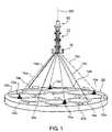
- FIG. 1diagrammatically illustrates one form of braiding apparatus that may be used for making braided devices in accordance with the present invention
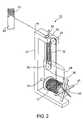
- FIG. 2illustrates one of the driven carriers for one of the filament spools in a commercially available braiding machine which may be used in the apparatus of FIG. 1 ;
- FIG. 3illustrates a preferred manner of tensioning each of the filaments from its respective spool toward the braiding point in order to produce a uniform tension such as to reduce the possibility of filament rupture or deformation as well as filament entanglement;
- FIGS. 4 and 5illustrate one loading arrangement for loading the braiding apparatus of FIG. 1 to produce a particular braid pattern, commonly called a Herringbone or 1 ⁇ 2 Braid Pattern, in which each filament of one group of spools is interweaved under and over two filaments of the other group of spools;
- FIG. 6illustrates the Herringbone or 1 ⁇ 2 Braid Pattern produced by the arrangement of FIGS. 4 and 5 ;
- FIGS. 7 and 8illustrate another loading arrangement for producing another broad pattern, commonly called a Diamond or Double Filament 1 ⁇ 1 Braid Pattern, in which two contiguous filaments of one group of spools are interleaved under and over two contiguous filaments of the other group of spools;
- FIG. 9illustrates the Diamond or Double Filament 1 ⁇ 1 Braid Pattern produced by the loading arrangement of FIGS. 7 and 8 ;
- FIGS. 10 and 11illustrate a further loading arrangement for producing another Diamond or Single Filament 1 ⁇ 1 Braid Pattern in which each filament of one group of spools is interweaved under and over a single filament of the second group of spools;
- FIG. 12illustrates the Diamond or Single Filament 1 ⁇ 1 Braid Pattern produced by the loading arrangement of FIGS. 10 and 11 ;
- FIG. 13illustrates a high level flow chart of a first embodiment of a braiding method according to the principle of the current invention
- FIG. 14illustrates a high level side view of a braided device in accordance with the principle of the current invention
- FIG. 15illustrates a high level flow chart of a second embodiment of a braiding method according to the principle of the current invention.
- FIG. 16 a – FIG. 16 dillustrate high level schematic views of the loading of a Maypole type braiding apparatus comprising 36 horn gears in accordance with the principle of the current invention.
- the present embodimentsenable a braided device comprising multiple filament types, in which at least one of the filament types define an independent stable structure of a symmetrical 1 ⁇ 1 sub-pattern, the multiple filament types being braided together into a single layer braided device exhibiting a uniform braid pattern.
- the present embodimentsalso enable a method of braiding multiple filaments types into a single uniform braid pattern in which one of the filament types define an integral symmetric 1 ⁇ 1 sub-pattern.
- the inventionis particularly useful when embodied in the “Maypole” type of braiding machine, as sold by Steeger USA, Inc. of Spartanburg, S.C., or Wardwell Braiding Machine Company, Central Falls, R.I.
- the inventionis therefore described below with respect to such a braiding machine.
- the inventionis particularly useful, and is therefore also described below, for making braided tubes of ultra-fine filaments, in the order of 50 ⁇ m and less, for use in implantable intraluminal devices, such as stents, stent grafts, prevention devices such as filters and stroke prevention devices such as diverters, for implantation in the human body.
- implantable intraluminal devicessuch as stents, stent grafts
- prevention devicessuch as filters and stroke prevention devices such as diverters
- filamentas used herein is to be understood to include strands, round wires, non-round wires, monofilaments, slit tape, multifilament yarn, braids or other longitudinal product.
- a single layer braidis defined as braid having a single distinct or discreet layer.
- a multi-layered braided structureis defined as a structure formed by braiding wherein the structure has a plurality of discreet and distinct layers. Typically, the layers of a multi-layered braided structure are bound by interlocking filaments, adhesives laminates, sewing or the like.
- FIG. 1diagrammatically illustrates a braiding machine of the foregoing Maypole type. It includes a plurality of carriers divided into two groups, 10 a , 10 b . Each carrier mounts a spool 12 ( FIG. 2 ) carrying supply of a filament 14 to be interwoven into a braid.
- the filaments 14 a , 14 b of all the carriers 10 a , 10 b , respectively,are converged towards the braiding axis BA through a braiding guide 16 located distally from the plurality of carriers 10 a , 10 b .
- Filaments 14 a , 14 bgenerally filaments 14 , are thus interwoven into a braid 70 about a mandrel 60 passing through the braiding guide 16 .
- the illustrated apparatusfurther includes an interweaving mechanism housed within a housing generally designated 20 for driving the carriers 10 a , 10 b and for paying out the filaments 14 from their respective spools 12 .
- the filamentsare thus payed out in an interweaving manner towards the braiding guide 16 to form the braid 70 about the mandrel 60 .
- the braiding apparatus illustrated in FIG. 1is of the vertical type; that is, the braiding axis BA of the mandrel 60 , about which the braid 70 is formed, extends in the vertical direction.
- a vertical-type braiding apparatusprovides more convenient access by the operator to various parts of the apparatus than the horizontal-type apparatus wherein the braid is formed about a horizontal axis. This is however not meant to be limiting in any way, and the invention is equally applicable to a horizontal-type apparatus.
- the interweaving mechanismis within a flat horizontal housing 20 , and includes a drive for driving the two groups of carriers 10 a , 10 b such as to interweave the filaments 14 of their respective spools as they are payed out towards the braiding guide 16 .
- Each carrier of the two groups 10 a , 10 b illustrated in FIG. 1carries a spool of the filament 14 to be payed out by the respective carrier.
- Carriers 10 aare arrayed in a circular array around the braiding axis BA and are driven in one direction about that axis.
- Carriers 10 bare also arrayed, in a circular array around the braiding axis BA, alternatingly with respect to carriers 10 a , and are driven in the opposite direction about that axis.
- FIG. 1illustrates the carriers 10 a in full lines as being driven about braiding axis BA in the clockwise direction; whereas carriers 10 b , shown in broken lines, are driven about braiding axis BA in the counter-clockwise direction.
- the flat horizontal housing 20houses a drive mechanism (to be more particularly described below with respect to FIGS. 4–12 ) which drives carriers 10 a along a circuitous path shown in full lines at 20 a , and drives the carriers 10 b along another circuitous path, shown by broken lines 20 b , intersecting with the full-line circuitous path 20 a .
- a drive mechanismto be more particularly described below with respect to FIGS. 4–12
- the circuitous path 20 a for carriers 10 aand also the circuitous path 20 b for carriers 10 b , bring the respective carriers 10 a , 10 b radially inwardly and outwardly with respect to the braiding axis BA, as the carriers move around the braiding axis.
- FIG. 2illustrates one structure that may be provided for each of the carriers 10 a , 10 b , mounting one of the spools 12 for the respective filament 14 .
- each carriertherein generally designated 10 , includes a vertically-extending mounting member 22 rotatably mounting the respective filament spool 12 for rotation about a horizontal axis.
- Spool 12could be mounted to rotate with respect to its shaft 12 ′ or could be fixed to its shaft and both rotated with respect to mounting member 22 .
- each carrier mounting member 22mounts an upper roller 24 and a lower roller 26 above the spool 12 , each roller being rotatably mounted about a horizontal axis.
- the upper roller 24is rotatably mounted on the carrier mounting member 22 ; whereas the lower roller 26 is rotatably mounted on a movable mounting member 28 which is vertically displaceable with respect to roller 24 and mounting member 22 .
- Each filament 14is fed from its respective spool 12 over the upper roller 24 , and under the lower, vertically-displaceable roller 26 , and through an upper eyelet 30 to the braiding guide 16 of FIG. 1 .
- Braiding guide 16converges all the filaments to produce the braid 70 over the mandrel 60 coaxial with the braiding axis BA.
- Braiding machines of this typeusually include a spring arrangement for applying the appropriate tension to the filaments.
- FIG. 2illustrates such a spring, at 32 , applied between the carrier mounting member 22 mounting the upper roller 24 , and the vertically-displaceable mounting member 28 mounting the lower roller 26 . The vertical displacement of mounting member 28 , and thereby of the lower roller 26 , is guided by a rod 34 movable within an opening in the upper roller mounting member 22 .
- FIG. 2further includes the vertically-displaceable mounting member 28 for the lower roller 26 as provided with a depending finger 36 movable within recesses defined by a retainer member 37 fixed to the spool shaft 12 ′ to restrain the spool shaft from free rotation.
- FIG. 3diagrammatically illustrates how the filaments 14 are preferably tensioned in a constant and uniform manner in order to minimize the possibility of over-tensioning likely to cause breakage or deformation, or under-tensioning likely to cause entanglement.
- the vertically displaceable roller 26 in each of the carriers 10is provided with a weight, shown at 39 , provided with a depending finger 36 engageable with retaining member 37 , which applies a gravitational tensioning force to the filament 14 passing under the lower roller 26 . Since this tensioning force is a gravitational force applied by the weight 39 , it is constant and uniform, and does not vary with the circuitous movements of the carriers as in the case where a spring tensioning force is applied to the filaments.
- Each of the carriers of the braiding machine diagrammatically illustrated in FIG. 1is driven by a rotor formed with four transfer notches for receiving a carrier at one side and transferring it to another rotor at the opposite side.
- Such rotorsare generally in the form of gears, commonly called horn gears, and are disposed within the flat horizontal housing 20 .
- the braiding machine diagrammatically illustrated in FIG. 1is actually a 8 horn gear braiding machine, which is shown half-loaded, i.e., equipped with 8-carriers only, one carrier per horn gear, divided into the two groups 10 a , 10 b.
- FIG. 4illustrates one of the horn gears, therein designated 40 . It includes circumferential teeth 42 and four transfer notches or pockets, sometimes called horns 44 , equally spaced around the circumference of the gear.
- FIG. 5illustrates eight of such horn gears 40 arrayed in a circular array around the braiding axis BA and intermeshing with each other so that each horn gear is rotated about its respective axis 46 but in an opposite direction with respect to the adjacent gears on its opposite sides.
- FIG. 5illustrates eight of such horn gears 40 arrayed in a circular array around the braiding axis BA and intermeshing with each other so that each horn gear is rotated about its respective axis 46 but in an opposite direction with respect to the adjacent gears on its opposite sides.
- one group 40 a of alternate horn gearsrotate clockwise about their respective axes 46 a , as shown by arrow 48 a
- the other group 40 b of horn gearsrotate in the opposite direction, e.g., counter-clockwise, about their respective axes 46 b.
- each horn gear 40As well known in braiding machines of this type, the rotation of each horn gear 40 about its respective axis 46 causes a carrier 10 to be received in a notch 44 from the horn gear at one side and to be transferred to notch 44 of the horn gear at the opposite side.
- the arrangementis such that the rotation of the two groups of horn gears 40 a , 40 b in opposite directions around their respective axes 46 a , 46 b is effective to drive the two groups of carriers 10 a , 10 b in opposite directions around the braiding axis BA, and along circuitous paths extending radially inwardly and outwardly with respect to the braiding axis.
- the resultsis to interweave the filaments 14 of the spools 12 carried by the two groups of carriers 10 a , 10 b as the filaments converge at the braiding guide 16 to form the braid 70 around the mandrel 60 .
- the mechanism for rotating the horn gears 40 a , 40 bsuch as to drive the carriers 10 a , 10 b in opposite directions along their respective serpentine paths, is well known in braiding machines of this type, as described for example in the published literature available with respect to the two commercial designs of braiding machines referred to above and incorporated herein by reference.
- Such braiding machinesare capable of producing various types of braid patterns, according to the manner of loading the horn gears 40 .
- three such braiding patternsare described below with respect to FIGS. 4–6 , FIGS. 7–9 , and FIGS. 10–12 , respectively.
- FIGS. 4–6relate to producing a regular braid pattern, which is the most commonly used one, sometimes called a Herringbone Pattern, or a 1 ⁇ 2 braid pattern.
- each filament of carriers group 10 ais passed over and under two filaments of carrier group 10 b .
- each horn gear 40is loaded with a carrier 10 as shown in FIG. 4 , namely with alternative notches 44 of each horn gear 40 occupied by a carrier, whereas the remaining alternate notches 44 of each horn gear 40 are not occupied by a carrier.
- FIG. 5illustrates the manner in which the carriers 10 are transferred from one horn gear 40 to the next as each horn gear rotates about its respective axis 46 .
- arrow 48 a in FIG. 5it will be assumed that the horn gears of group 40 a are rotated clockwise about their respective axis 46 a , whereas the horn gears of group 40 b are rotated counter-clockwise about their respective axes 46 b as indicated by arrow 48 b.
- FIG. 6illustrates the 1 ⁇ 2 braid pattern 51 produced in this set-up, wherein it will be seen that each filament 14 a from the carriers 10 a rotating in one direction about the braiding axis BA is interweaved over two and under two filaments 14 b of the carriers 10 b rotating in the opposite direction around the braiding axis.
- the 1 ⁇ 2 braid patternis characterized by relatively large area coverage of the braid, however the structural stability of the braid pattern is somewhat lower than the 1 ⁇ 1 braid pattern to be discussed further below.
- FIG. 7illustrates the set-up of the horn gears 40 for producing a double filament diamond braid pattern, also known as a double filament 1 ⁇ 1 braid pattern, in which two filaments 14 a from carriers 10 a rotating in one direction run contiguously and are interweaved over and under two filaments 14 b from carriers 10 b rotating in the opposite direction.
- FIG. 7illustrates the loading arrangement for the horn gears to produce such a pattern, in which it will be seen that two adjacent notches 44 are loaded with a carrier, whereas the remaining two adjacent notches are not loaded.
- FIG. 8illustrates how the carriers are transferred from one horn gear to the next during the rotation of all the horn gears about their respective axes 46 .
- FIG. 9illustrates the double filament 1 ⁇ 1 braid pattern 52 so produced, wherein it will be seen that two filaments 14 a each from a carrier 10 a rotated in the clockwise direction are run contiguously and are interwoven over and under two filaments 14 b each from a carrier 10 b rotated by the horn gears 40 b in the counter-clockwise direction.
- the double filament 1 ⁇ 1 braid patternis characterized by an improved structural stability of the braid pattern but reduced coverage, as compared to the 1 ⁇ 2 braid pattern described above in relation to FIG. 6 .
- FIG. 10–12illustrate the manner of producing a braid pattern also of a diamond or 1 ⁇ 1 braid pattern but in which each filament 14 a from the carriers 10 a is interwoven over and under a single filament 14 b from the carriers 10 b .
- the horn gears 40are loaded with a carrier 10 in only one of the notches 44 , the remaining three notches 44 being without carriers.
- FIG. 12illustrates the single filament 1 ⁇ 1 braid pattern 53 so produced, wherein it will be seen that each filament 14 a of a carrier 10 a is interwoven over and under each filament 14 b of a carrier 10 b .
- the single filament 1 ⁇ 1 braid patternis characterized by improved structural stability of the braid pattern as compared to the 1 ⁇ 2 braid pattern described above in relation to FIG. 6 and reduced coverage as compared to the double filament 1 ⁇ 1 braid pattern described above in relation to FIG. 9 .
- the invention of the present applicationis concerned primarily with a single layer braided device comprising multiple types of filaments 14 , the filaments exhibiting differing mechanical characteristics, the filaments of at least one type being braided in an integrated symmetrical lxI sub-pattern.
- the more rigid filamentis braided as an integrated symmetrical 1 ⁇ 1 sub-pattern.
- the integrated symmetrical sub-pattern of filamentssupplies at least 75% of the overall rigidity of the braided device, and even more preferably at least 90% of the overall rigidity of the braided device.
- the integrated symmetrical sub-pattern of filamentssupplies radio-opacity for the braided device, the filaments of the sub-pattern being comprised of a radiopaque substance of sufficient cross section to be visible under commercially available fluoroscopic equipment.
- FIG. 13illustrates a high level flow chart of a first embodiment of a braiding method according to the principle of the current invention, in which filament multiple filament types, comprising a first filament type hereinafter being designated F 1 , and a second filament type hereinafter designated F 2 are braided together into a braid exhibiting a uniform braid pattern, in which filaments of type F 1 define an integrated symmetrical 1 ⁇ 1 sub-pattern.
- the braiding apparatusis selected, the selected braiding apparatus being characterized by having horn gears, the number of horn gears of the selected braiding apparatus being hereinafter designated N.
- Nthe number of carriers is equal to the number of horn gears.
- step 110the braid pattern to be utilized in the operation of the braiding apparatus selected in step 100 is selected.
- the braid patternis chosen from the possible braid patterns producible by the appropriate loading of the N horn gears of the braiding apparatus selected in step 100 .
- the multiple filament types to be utilizedcomprising first filament type F 1 , and second filament type F 2 .
- the methodis herein being described as having two types of filaments, however this is not meant to be limiting in any way. Three or more types of filaments may be utilized without exceeding the scope of the invention.
- Filament type F 1is the filament type that is to be braided in an integrated symmetrical 1 ⁇ 1 sub-pattern.
- the more rigid filament type of the multiple filament types utilizedis selected as F 1 .
- M filaments of type F 1are symmetrically and evenly placed on carriers. Symmetrical and even placement as used herein includes circular symmetry as well as even distribution among the carriers of the braiding apparatus such that selected carriers are evenly spread out in the circular array of carriers 10 a and 10 b .
- half of M filaments of type F 1are loaded on carriers 10 a of FIG. 1 , carriers 10 a being selected symmetrically and evenly from among all carriers 10 a
- half of M filaments of type F 1are loaded on carriers 10 b of FIG. 1
- carriers 10 bbeing selected symmetrically and evenly on carriers 10 b of FIG. 1 from among all carriers 10 b .
- the selection of carriers 10 a and 10 bis not independent, and carriers 10 a and 10 b are to be selected to symmetrical and evenly spaced respect to all carriers 10 .
- step 160the remaining carriers are loaded with filaments of type F 2 .
- the remaining carriersare loaded with filaments of type F 2 .
- N-M unloaded carrierswhich are loaded with filaments F 2 , thus in the exemplary embodiment indicated above, utilizing a single filament 1 ⁇ 1 braid type, there are 48 filaments F 2 .
- step 170the braiding apparatus is operated in a manner known to those skilled in the art to produce a braided device comprising multiple filament types, in which one of the filament types define an independent stable structure of a symmetrical 1 ⁇ 1 sub-pattern, the multiple filament types being braided together into a braided device exhibiting a uniform braid pattern.
- FIG. 14illustrates a high level side view of a braided device 80 in accordance with the principle of the current invention, comprising filament types F 1 and filament type F 2 .
- Filament type F 1is illustrated with heavier lines than filament type F 2 , however this is not meant to be limiting in any way.
- Filament types F 1 and F 2form a braided device 80 , in which filament types F 1 form an integrated symmetrical 1 ⁇ 1 sub-pattern.
- FIG. 15illustrates a high level flow chart of a second embodiment of a braiding method according to the principle of the current invention, in which multiple filament types, comprising a first filament type hereinafter being designated F 1 , and a second filament type hereinafter designated F 2 , and a third filament type hereinafter being designated F 3 , are braided together into a braid exhibiting a uniform braid pattern, in which filaments of type F 1 define a first integrated symmetrical 1 ⁇ 1 sub-pattern and filaments of type F 2 define a second integrated symmetrical 1 ⁇ 1 sub-pattern.
- the braiding methodis herein being described as having two individual integrated symmetrical 1 ⁇ 1 sub-patterns, however this is not meant to be limiting in any way. In another embodiment three or more multiple integrated sub-patterns are defined within an overall uniform braid pattern without exceeding the scope of the invention.
- the overall braid patternis a 1 ⁇ 2 braid pattern as described above in relation to FIG. 4–6 .
- the overall braid patternis a double filament 1 ⁇ 1 braid pattern as described above in relation to FIG. 7–9 .
- the overall braid patternis a single filament 1 ⁇ 1 braid pattern as described above in relation to FIG. 10–12 .
- the braiding apparatusis selected, and the number of horn gears of the braiding apparatus is designated N.
- step 210the braid pattern to be utilized in the operation of the braiding apparatus selected in step 200 is selected.
- the braid patternis chosen from the possible braid patterns producible by the appropriate loading of the N horn gears of the braiding apparatus selected in step 200 .
- step 220the types of filaments to be utilized, F 1 and F 2 are selected.
- a third filament type, F 3which comprises the balance of the filaments to be utilized, is also selected.
- the methodis herein being described as having three different types of filaments, however this is not meant to be limiting in any way.
- filament type F 3is in all respects identical with filament type F 1 or F 2 , but is not part of the first or second integrated 1 ⁇ 1 symmetrical sub-pattern of filament type F 1 or F 2 , respectively.
- filament types F 1 and F 2are in all respects identical but differ from filament type F 3 , and first and second integrated 1 ⁇ 1 symmetrical sub-patterns of filament types F 1 and F 2 , respectively are created.
- step 230the possible values for the number of filaments in the integrated symmetrical 1 ⁇ 1 sub-pattern, herein designated generally as M, are calculated. Values for M meet the requirements of Equation 1 and Equation 2 described above.
- step 240the results of step 230 are analyzed.
- M 1the number of filaments of type F 1 in the first integrated symmetrical 1 ⁇ 1 sub-pattern
- M 2the number of filaments of type F 2 in the second integrated symmetrical 1 ⁇ 1 sub-pattern
- M 1the number of filaments of type F 1 in the first integrated symmetrical 1 ⁇ 1 sub-pattern
- M 2the number of filaments of type F 2 in the second integrated symmetrical 1 ⁇ 1 sub-pattern
- the more rigid filament typeis selected as F 1 , and the mechanical characteristics of F 1 together with the required overall mechanical device characteristics are reviewed. The minimum value for M 1 that supplies the device with the required mechanical characteristics is selected.
- the more rigid filament typeis selected as filament type F 1 and F 2 , and the mechanical characteristics of F 1 , F 2 together with the required overall mechanical device characteristics are reviewed. The minimum value for M 1 and M 2 that supply the device with the required mechanical characteristics is selected.
- M 1 filaments of type F 1are symmetrically and evenly placed on carriers. Symmetrical and even placement as used herein includes circular symmetry as well as even distribution among the carriers of the braiding apparatus such that selected carriers are evenly spread out in the circular array of carriers 10 a and 10 b .
- Symmetrical and even placementincludes circular symmetry as well as even distribution among the carriers of the braiding apparatus such that selected carriers are evenly spread out in the circular array of carriers 10 a and 10 b .
- half of M 1 filaments of type F 1are loaded on carriers 10 a of FIG. 1 , carriers 10 a being selected symmetrically and evenly from among all carriers 10 a
- half of M 1 filaments of type F 1are loaded on carriers 10 b of FIG. 1
- carriers 10 bbeing selected symmetrically and evenly on carriers 10 b of FIG. 1 from among all carriers 10 b .
- the selection of carriers 10 a and 10 bis not independent, and carriers 10 a and 10 b are to be selected to symmetrical and evenly spaced respect
- M 2 filaments of type F 2are symmetrically placed on carriers. Symmetrical and even placement as used herein includes circular symmetry as well as even distribution among the carriers of the braiding apparatus such that selected carriers are evenly spread out in the circular array of carriers 10 a and 10 b .
- Symmetrical and even placementincludes circular symmetry as well as even distribution among the carriers of the braiding apparatus such that selected carriers are evenly spread out in the circular array of carriers 10 a and 10 b .
- half of M 2 filaments of type F 2are loaded on carriers 10 a of FIG. 1 , carriers 10 a being selected symmetrically and evenly from among all carriers 10 a
- half of M 2 filaments of type F 2are loaded on carriers 10 b of FIG. 1 , carriers 10 b being selected symmetrically and evenly on carriers 10 b of FIG. 1 from among all carriers 10 b .
- the selection of carriers 10 a and 10 bis not independent, and carriers 10 a and 10 b are to be selected to symmetrical and evenly spaced respect to all carriers 10 . It is to be further noted that placement of filament type F 2 is independent of placement of filament type F 1 , thus filament type F 2 need not be placed symmetrically and evenly in relation to filament type F 1 In a preferred embodiment, placement of filament type F 2 is done symmetrically in relation to placement of filament type F 1 , thus contributing to the overall symmetry of the braided device.
- step 270the remaining carriers are loaded with filaments type F 3 .
- the overall braid patternrepresents a 1 ⁇ 2 braid pattern, or a double filament 1 ⁇ 1 braid pattern there are 2N ⁇ (M 1 +M 2 ) unloaded carriers that are loaded with filament type F 3 .
- step 280the braiding apparatus is operated in a manner known to those skilled in the art to produce a braided device comprising multiple filament types in which first filament type F 1 , second filament type F 2 , and third filament type F 3 , are braided together into a braided device exhibiting a uniform braid pattern, in which filaments of type F 1 define a first integrated symmetrical 1 ⁇ 1 sub-pattern and filaments of type F 2 define a second integrated symmetrical 1 ⁇ 1 sub-pattern.
- the braiding apparatusis herein illustrated as a two dimensional table, in which the first row represents horn gears being sequentially numbered, with rows below indicating the loading, and direction of travel indicated by an arrow, of carriers on the horn gears.
- FIG. 16 aillustrates the loading of carriers with filament type F 1 and filament type F 2 to produce a braided device exhibiting a uniform 1 ⁇ 1 single filament braid pattern, in which filaments of type F 1 define an integrated symmetrical 1 ⁇ 1 sub-pattern in accordance with the principle of the current invention.
- the braid patterncomprises a single filament 1 ⁇ 1 braid pattern
- the number of carriersis equal to the number of horn gears.
- the carriers on which filament type F 1 are loadedare illustrated with a spotted background for ease of identification.
- the balance of the carriersare loaded with filament type F 2 , and thus filament type F 1 forms an integrated symmetrical 1 ⁇ 1 sub-pattern comprising 4 filaments within the braided device comprising a total of 36 filaments.
- one type of filamentis designated F 1 , which is loaded onto the carriers of the horn gears as described above in relation to FIG. 16 a , and the balance of the carriers are loaded as symmetrically and evenly as possible split among the remaining filament types.
- FIG. 16 billustrates the loading of carriers with filament type F 1 and filament type F 2 to produce a braided device exhibiting a uniform 1 ⁇ 2 braid pattern, in which filaments of type F 1 define an integrated symmetrical 1 ⁇ 1 sub-pattern in accordance with the principle of the current invention.
- the number of carriersis equal to twice the number of horn gears.
- the carriers on which filament type F 1 are loadedare illustrated with a spotted background for ease of identification.
- a single carrier or each of four horn gears, labeled 1 , 10 , 19 , 28being placed symmetrically and evenly spaced among the horn gears of FIG.
- filament type F 1forms an integrated symmetrical 1 ⁇ 1 sub-pattern comprising 4 filaments within the braided device comprising a total of 72 filaments exhibiting a 1 ⁇ 2 braid pattern.
- one type of filamentis designated F 1 , which is loaded onto the carriers of the horn gears as described above in relation to FIG. 16 b , and the balance of the carriers are loaded as symmetrically and evenly as possible split among the remaining filament types.
- FIG. 16 cillustrates the loading of carriers with filament type F 1 and filament type F 2 to produce a braided devices exhibiting a uniform double filament 1 ⁇ 1 braid pattern, in which filaments of type F 1 define an integrated symmetrical 1 ⁇ 1 sub-pattern in accordance with the principle of the current invention.
- the number of carriersis equal to twice the number of horn gears.
- the carriers on which filament type F 1 are loadedare illustrated with a spotted background for ease of identification.
- the balance of the carriersare loaded with filament type F 2 , and thus filament type F 1 forms an integrated symmetrical 1 ⁇ 1 sub-pattern comprising 4 filaments within the braided device comprising a total of 72 filaments exhibiting a double filament 1 ⁇ 1 braid pattern.
- one type of filamentis designated F 1 , which is loaded onto the carriers of the horn gears as described above in relation to FIG. 16 d , and the balance of the carriers are loaded as symmetrically and evenly as possible split among the remaining filament types
- FIG. 16 dillustrates the loading of carriers with filament types F 1 , F 2 and F3, to produce a braided device exhibiting a uniform 1 ⁇ 2 braid pattern, in which filaments of type F 2 define a first integrated symmetrical 1 ⁇ 1 sub-pattern, and filaments of type F 2 define a second integrated symmetrical 1 ⁇ 1 sub-pattern in accordance with the principle of the current invention, and filament types F 3 defines the balance of filaments used in the braided device.
- the number of carriersis equal to twice the number of horn gears.
- the carriers on which filament type F 1 are loadedare illustrated with a spotted background for ease of identification, and the carriers on which filament type F 2 are loaded are illustrated with a diagonal background for ease of identification.
- a single carrier of each of four horn gears, labeled 1 , 10 , 19 , 28being placed symmetrically and evenly spaced among the horn gears of FIG. 16 d , are loaded with filament type F 1 , with the carriers loaded with filament type F 1 of horn gear 1 and 19 traveling in the opposing direction from the carriers loaded with filament type F 1 of horn gears 10 and 28 .
- filament type F 1forms a first integrated symmetrical 1 ⁇ 1 sub-pattern comprising 4 filaments
- filament type F 2forms a second integrated symmetrical 1 ⁇ 1 sub-pattern comprising 12 filaments, within the braided device comprising a total of 72 filaments.
- braided devicerefers solely to the braid pattern, and not to the overall symmetry of the device.
- method and braided device described hereinis primarily concerned with at least one symmetrical 1 ⁇ 1 sub-pattern, preferably however the overall symmetry of the braided device is preserved.
- equations 1 and 2provide a means for proper selection of a braiding machine, which is capable of producing a braided device comprising multiple filament types having an integrated symmetrical 1 ⁇ 1 sub-pattern of at least one filament type. Such a selection requires calculating the desired number of filaments in the symmetrical 1 ⁇ 1 sub-pattern, and selecting a braiding machine having the appropriate number of horn gears such that equations 1 and 2 are satisfied for the desired number of filaments in the sub-pattern.
- the present inventionenable a braided device comprising multiple filament types, in which at least one of the filament types define an independent stable structure of a symmetrical 1 ⁇ 1 sub-pattern, the multiple filament types being braided together into a single braided device exhibiting a uniform braid pattern.
- the present embodimentsalso enable a method of braiding multiple filaments types into a single uniform braid pattern in which one of the filament types define an integral symmetric 1 ⁇ 1 sub-pattern.
Landscapes
- Engineering & Computer Science (AREA)
- Textile Engineering (AREA)
- Manufacturing & Machinery (AREA)
- Braiding, Manufacturing Of Bobbin-Net Or Lace, And Manufacturing Of Nets By Knotting (AREA)
Abstract
Description
M=even
N/M=
Claims (16)
Priority Applications (1)
| Application Number | Priority Date | Filing Date | Title |
|---|---|---|---|
| US11/022,872US7275471B2 (en) | 2003-12-29 | 2004-12-28 | Mixed wire braided device with structural integrity |
Applications Claiming Priority (2)
| Application Number | Priority Date | Filing Date | Title |
|---|---|---|---|
| US53257103P | 2003-12-29 | 2003-12-29 | |
| US11/022,872US7275471B2 (en) | 2003-12-29 | 2004-12-28 | Mixed wire braided device with structural integrity |
Publications (2)
| Publication Number | Publication Date |
|---|---|
| US20050257674A1 US20050257674A1 (en) | 2005-11-24 |
| US7275471B2true US7275471B2 (en) | 2007-10-02 |
Family
ID=35373949
Family Applications (1)
| Application Number | Title | Priority Date | Filing Date |
|---|---|---|---|
| US11/022,872Expired - Fee RelatedUS7275471B2 (en) | 2003-12-29 | 2004-12-28 | Mixed wire braided device with structural integrity |
Country Status (1)
| Country | Link |
|---|---|
| US (1) | US7275471B2 (en) |
Cited By (59)
| Publication number | Priority date | Publication date | Assignee | Title |
|---|---|---|---|---|
| US20060271153A1 (en)* | 2005-05-25 | 2006-11-30 | Chestnut Medical Technologies, Inc. | System and method for delivering and deploying an occluding device within a vessel |
| US20090270970A1 (en)* | 2001-07-09 | 2009-10-29 | Surpass Medical Ltd. | Implantable intraluminal device and method of using same in treating aneurysms |
| US20110230955A1 (en)* | 2008-11-24 | 2011-09-22 | Vascular Graft Solutions Ltd. | External stent |
| US8147534B2 (en) | 2005-05-25 | 2012-04-03 | Tyco Healthcare Group Lp | System and method for delivering and deploying an occluding device within a vessel |
| US8261648B1 (en) | 2011-10-17 | 2012-09-11 | Sequent Medical Inc. | Braiding mechanism and methods of use |
| US8273101B2 (en) | 2005-05-25 | 2012-09-25 | Tyco Healthcare Group Lp | System and method for delivering and deploying an occluding device within a vessel |
| US8382825B2 (en) | 2004-05-25 | 2013-02-26 | Covidien Lp | Flexible vascular occluding device |
| US8394119B2 (en) | 2006-02-22 | 2013-03-12 | Covidien Lp | Stents having radiopaque mesh |
| US8398701B2 (en) | 2004-05-25 | 2013-03-19 | Covidien Lp | Flexible vascular occluding device |
| US8617234B2 (en) | 2004-05-25 | 2013-12-31 | Covidien Lp | Flexible vascular occluding device |
| US8623067B2 (en) | 2004-05-25 | 2014-01-07 | Covidien Lp | Methods and apparatus for luminal stenting |
| KR101381800B1 (en)* | 2012-07-16 | 2014-04-07 | 박춘오 | Apparatus for generating a stent |
| US8826791B2 (en) | 2011-10-17 | 2014-09-09 | Sequent Medical, Inc. | Braiding mechanism and methods of use |
| US8911490B2 (en) | 2012-03-27 | 2014-12-16 | Medtronic Vascular, Inc. | Integrated mesh high metal to vessel ratio stent and method |
| US9005270B2 (en) | 2012-03-27 | 2015-04-14 | Medtronic Vascular, Inc. | High metal to vessel ratio stent and method |
| US9078658B2 (en) | 2013-08-16 | 2015-07-14 | Sequent Medical, Inc. | Filamentary devices for treatment of vascular defects |
| US9114001B2 (en) | 2012-10-30 | 2015-08-25 | Covidien Lp | Systems for attaining a predetermined porosity of a vascular device |
| US9155647B2 (en) | 2012-07-18 | 2015-10-13 | Covidien Lp | Methods and apparatus for luminal stenting |
| US9157174B2 (en) | 2013-02-05 | 2015-10-13 | Covidien Lp | Vascular device for aneurysm treatment and providing blood flow into a perforator vessel |
| US9259337B2 (en) | 2007-06-04 | 2016-02-16 | Sequent Medical, Inc. | Methods and devices for treatment of vascular defects |
| US20160168769A1 (en)* | 2014-12-12 | 2016-06-16 | Woven Orthopedic Technologies, Llc | Methods and systems for manufacturing woven retention devices |
| US9393136B2 (en) | 2012-03-27 | 2016-07-19 | Medtronic Vascular, Inc. | Variable zone high metal to vessel ratio stent and method |
| US9447529B2 (en) | 2013-11-26 | 2016-09-20 | A-Z Chuteworks L.L.C. | Cord material and methods of using same |
| US9452070B2 (en) | 2012-10-31 | 2016-09-27 | Covidien Lp | Methods and systems for increasing a density of a region of a vascular device |
| US9597087B2 (en) | 2008-05-02 | 2017-03-21 | Sequent Medical, Inc. | Filamentary devices for treatment of vascular defects |
| US9629635B2 (en) | 2014-04-14 | 2017-04-25 | Sequent Medical, Inc. | Devices for therapeutic vascular procedures |
| US9675482B2 (en) | 2008-05-13 | 2017-06-13 | Covidien Lp | Braid implant delivery systems |
| US9808291B2 (en) | 2014-08-05 | 2017-11-07 | Woven Orthopedic Technologies, Llc | Woven retention devices, systems and methods |
| US9907593B2 (en) | 2014-08-05 | 2018-03-06 | Woven Orthopedic Technologies, Llc | Woven retention devices, systems and methods |
| US9918720B2 (en) | 2009-11-05 | 2018-03-20 | Sequent Medical Inc. | Multiple layer filamentary devices for treatment of vascular defects |
| US9943427B2 (en) | 2012-11-06 | 2018-04-17 | Covidien Lp | Shaped occluding devices and methods of using the same |
| US9943351B2 (en) | 2014-09-16 | 2018-04-17 | Woven Orthopedic Technologies, Llc | Woven retention devices, systems, packaging, and related methods |
| US9955976B2 (en) | 2013-08-16 | 2018-05-01 | Sequent Medical, Inc. | Filamentary devices for treatment of vascular defects |
| US9970137B2 (en) | 2013-03-12 | 2018-05-15 | DePuy Synthes Products, Inc. | Variable porosity intravascular implant and manufacturing method |
| US10004618B2 (en) | 2004-05-25 | 2018-06-26 | Covidien Lp | Methods and apparatus for luminal stenting |
| US10052218B2 (en) | 2011-04-18 | 2018-08-21 | Vascular Graft Solutions Ltd. | Devices and methods for deploying implantable sleeves over blood vessels |
| US10167582B1 (en)* | 2016-05-13 | 2019-01-01 | Stryker Corporation | Braided filament with particularized strand compositions and methods of manufacturing and using same |
| US10299544B2 (en) | 2014-12-10 | 2019-05-28 | Nike, Inc. | Last system for articles with braided components |
| US10555758B2 (en) | 2015-08-05 | 2020-02-11 | Woven Orthopedic Technologies, Llc | Tapping devices, systems and methods for use in bone tissue |
| US10555581B2 (en) | 2015-05-26 | 2020-02-11 | Nike, Inc. | Braided upper with multiple materials |
| US10674791B2 (en) | 2014-12-10 | 2020-06-09 | Nike, Inc. | Braided article with internal midsole structure |
| US10743618B2 (en) | 2015-05-26 | 2020-08-18 | Nike, Inc. | Hybrid braided article |
| US10806210B2 (en) | 2017-05-31 | 2020-10-20 | Nike, Inc. | Braided articles and methods for their manufacture |
| US10863794B2 (en) | 2013-06-25 | 2020-12-15 | Nike, Inc. | Article of footwear having multiple braided structures |
| US10893931B2 (en)* | 2017-10-16 | 2021-01-19 | Amrita Vishwa Vidyapeetham | Strong, flexible, and thrombus-free woven nanotextile based vascular grafts, and method of production thereof |
| US11051573B2 (en) | 2017-05-31 | 2021-07-06 | Nike, Inc. | Braided articles and methods for their manufacture |
| US11103028B2 (en) | 2015-08-07 | 2021-08-31 | Nike, Inc. | Multi-layered braided article and method of making |
| US11202483B2 (en) | 2017-05-31 | 2021-12-21 | Nike, Inc. | Braided articles and methods for their manufacture |
| US11219266B2 (en) | 2013-06-25 | 2022-01-11 | Nike, Inc. | Article of footwear with braided upper |
| US11253261B2 (en) | 2016-03-17 | 2022-02-22 | Swaminathan Jayaraman | Occluding anatomical structures |
| US11291453B2 (en) | 2019-03-15 | 2022-04-05 | Sequent Medical, Inc. | Filamentary devices having a flexible joint for treatment of vascular defects |
| US11317921B2 (en) | 2019-03-15 | 2022-05-03 | Sequent Medical, Inc. | Filamentary devices for treatment of vascular defects |
| US11395681B2 (en) | 2016-12-09 | 2022-07-26 | Woven Orthopedic Technologies, Llc | Retention devices, lattices and related systems and methods |
| US11559309B2 (en) | 2019-03-15 | 2023-01-24 | Sequent Medical, Inc. | Filamentary devices for treatment of vascular defects |
| US12023034B2 (en) | 2020-03-11 | 2024-07-02 | Microvention, Inc. | Devices for treatment of vascular defects |
| US12070220B2 (en) | 2020-03-11 | 2024-08-27 | Microvention, Inc. | Devices having multiple permeable shells for treatment of vascular defects |
| US12232737B2 (en) | 2016-03-17 | 2025-02-25 | Eclipse Medical Limited | Occluding anatomical structures |
| US12408925B2 (en) | 2020-03-11 | 2025-09-09 | Microvention, Inc. | Multiple layer devices for treatment of vascular defects |
| US12419764B2 (en) | 2018-03-12 | 2025-09-23 | Fluid Biomed Inc. | Bioabsorbable flow diverting scaffold |
Families Citing this family (17)
| Publication number | Priority date | Publication date | Assignee | Title |
|---|---|---|---|---|
| US20050257647A1 (en)* | 2004-05-19 | 2005-11-24 | David Baker | Pneumatic ratchet with forward/reverse actuator |
| CN102587032B (en)* | 2011-01-13 | 2013-09-18 | 江苏苏净集团有限公司 | Wastewater treatment filler braiding machine and using method thereof |
| US9394636B2 (en) | 2013-02-06 | 2016-07-19 | Federal-Mogul Powertrain, Inc. | Enhanced braided sleeve and method of construction thereof |
| RU2660291C2 (en)* | 2013-02-06 | 2018-07-05 | Федерал-Могал Пауэртрейн, Инк. | Enhanced braided sleeve and method for production thereof |
| US10603157B2 (en) | 2013-03-13 | 2020-03-31 | DePuy Synthes Products, Inc. | Braid implant delivery and retraction device with distal engagement |
| US10561509B2 (en) | 2013-03-13 | 2020-02-18 | DePuy Synthes Products, Inc. | Braided stent with expansion ring and method of delivery |
| JP6238678B2 (en)* | 2013-10-18 | 2017-11-29 | 株式会社市川鉄工 | Yarn supply device for torsion lace machine |
| TWI578926B (en)* | 2014-06-13 | 2017-04-21 | 台灣百和工業股份有限公司 | Manufacturing method of braid tip and structure of braid thereof |
| US10206796B2 (en) | 2014-08-27 | 2019-02-19 | DePuy Synthes Products, Inc. | Multi-strand implant with enhanced radiopacity |
| US10280538B2 (en) | 2015-05-26 | 2019-05-07 | Nike, Inc. | Braiding machine and method of forming an article incorporating a moving object |
| US9920462B2 (en)* | 2015-08-07 | 2018-03-20 | Nike, Inc. | Braiding machine with multiple rings of spools |
| US10076428B2 (en) | 2016-08-25 | 2018-09-18 | DePuy Synthes Products, Inc. | Expansion ring for a braided stent |
| US10292851B2 (en) | 2016-09-30 | 2019-05-21 | DePuy Synthes Products, Inc. | Self-expanding device delivery apparatus with dual function bump |
| AU2019204522A1 (en) | 2018-07-30 | 2020-02-13 | DePuy Synthes Products, Inc. | Systems and methods of manufacturing and using an expansion ring |
| US10278848B1 (en) | 2018-08-06 | 2019-05-07 | DePuy Synthes Products, Inc. | Stent delivery with expansion assisting delivery wire |
| US10456280B1 (en) | 2018-08-06 | 2019-10-29 | DePuy Synthes Products, Inc. | Systems and methods of using a braided implant |
| US11039944B2 (en) | 2018-12-27 | 2021-06-22 | DePuy Synthes Products, Inc. | Braided stent system with one or more expansion rings |
Citations (4)
| Publication number | Priority date | Publication date | Assignee | Title |
|---|---|---|---|---|
| US4158984A (en)* | 1977-03-09 | 1979-06-26 | Aeroquip Corporation | Method of braiding |
| US4754685A (en)* | 1986-05-12 | 1988-07-05 | Raychem Corporation | Abrasion resistant braided sleeve |
| US6250193B1 (en)* | 1996-12-02 | 2001-06-26 | A & P Technology, Inc. | Braided structure with elastic bias strands |
| US20020066360A1 (en)* | 2000-10-31 | 2002-06-06 | Greenhalgh E. Skott | Supported lattice for cell cultivation |
- 2004
- 2004-12-28USUS11/022,872patent/US7275471B2/ennot_activeExpired - Fee Related
Patent Citations (4)
| Publication number | Priority date | Publication date | Assignee | Title |
|---|---|---|---|---|
| US4158984A (en)* | 1977-03-09 | 1979-06-26 | Aeroquip Corporation | Method of braiding |
| US4754685A (en)* | 1986-05-12 | 1988-07-05 | Raychem Corporation | Abrasion resistant braided sleeve |
| US6250193B1 (en)* | 1996-12-02 | 2001-06-26 | A & P Technology, Inc. | Braided structure with elastic bias strands |
| US20020066360A1 (en)* | 2000-10-31 | 2002-06-06 | Greenhalgh E. Skott | Supported lattice for cell cultivation |
Cited By (133)
| Publication number | Priority date | Publication date | Assignee | Title |
|---|---|---|---|---|
| US20090270970A1 (en)* | 2001-07-09 | 2009-10-29 | Surpass Medical Ltd. | Implantable intraluminal device and method of using same in treating aneurysms |
| US7942925B2 (en) | 2001-07-09 | 2011-05-17 | Surpass Medical Ltd. | Implantable intraluminal device and method of using same in treating aneurysms |
| US8419787B2 (en) | 2001-11-23 | 2013-04-16 | Surpass Medical Ltd | Implantable intraluminal device and method of using same in treating aneurysms |
| US9855047B2 (en) | 2004-05-25 | 2018-01-02 | Covidien Lp | Flexible vascular occluding device |
| US9050205B2 (en) | 2004-05-25 | 2015-06-09 | Covidien Lp | Methods and apparatus for luminal stenting |
| US11771433B2 (en) | 2004-05-25 | 2023-10-03 | Covidien Lp | Flexible vascular occluding device |
| US9393021B2 (en) | 2004-05-25 | 2016-07-19 | Covidien Lp | Flexible vascular occluding device |
| US9801744B2 (en) | 2004-05-25 | 2017-10-31 | Covidien Lp | Methods and apparatus for luminal stenting |
| US8617234B2 (en) | 2004-05-25 | 2013-12-31 | Covidien Lp | Flexible vascular occluding device |
| US9295568B2 (en) | 2004-05-25 | 2016-03-29 | Covidien Lp | Methods and apparatus for luminal stenting |
| US8382825B2 (en) | 2004-05-25 | 2013-02-26 | Covidien Lp | Flexible vascular occluding device |
| US9125659B2 (en) | 2004-05-25 | 2015-09-08 | Covidien Lp | Flexible vascular occluding device |
| US8398701B2 (en) | 2004-05-25 | 2013-03-19 | Covidien Lp | Flexible vascular occluding device |
| US10918389B2 (en) | 2004-05-25 | 2021-02-16 | Covidien Lp | Flexible vascular occluding device |
| US10004618B2 (en) | 2004-05-25 | 2018-06-26 | Covidien Lp | Methods and apparatus for luminal stenting |
| US12042411B2 (en) | 2004-05-25 | 2024-07-23 | Covidien Lp | Methods and apparatus for luminal stenting |
| US8623067B2 (en) | 2004-05-25 | 2014-01-07 | Covidien Lp | Methods and apparatus for luminal stenting |
| US8628564B2 (en) | 2004-05-25 | 2014-01-14 | Covidien Lp | Methods and apparatus for luminal stenting |
| US10765542B2 (en) | 2004-05-25 | 2020-09-08 | Covidien Lp | Methods and apparatus for luminal stenting |
| US9204983B2 (en) | 2005-05-25 | 2015-12-08 | Covidien Lp | System and method for delivering and deploying an occluding device within a vessel |
| US8236042B2 (en) | 2005-05-25 | 2012-08-07 | Tyco Healthcare Group Lp | System and method for delivering and deploying an occluding device within a vessel |
| US8267985B2 (en) | 2005-05-25 | 2012-09-18 | Tyco Healthcare Group Lp | System and method for delivering and deploying an occluding device within a vessel |
| US8147534B2 (en) | 2005-05-25 | 2012-04-03 | Tyco Healthcare Group Lp | System and method for delivering and deploying an occluding device within a vessel |
| US10064747B2 (en) | 2005-05-25 | 2018-09-04 | Covidien Lp | System and method for delivering and deploying an occluding device within a vessel |
| US8273101B2 (en) | 2005-05-25 | 2012-09-25 | Tyco Healthcare Group Lp | System and method for delivering and deploying an occluding device within a vessel |
| US9381104B2 (en) | 2005-05-25 | 2016-07-05 | Covidien Lp | System and method for delivering and deploying an occluding device within a vessel |
| US9198666B2 (en) | 2005-05-25 | 2015-12-01 | Covidien Lp | System and method for delivering and deploying an occluding device within a vessel |
| US20060271153A1 (en)* | 2005-05-25 | 2006-11-30 | Chestnut Medical Technologies, Inc. | System and method for delivering and deploying an occluding device within a vessel |
| US9095343B2 (en) | 2005-05-25 | 2015-08-04 | Covidien Lp | System and method for delivering and deploying an occluding device within a vessel |
| US10322018B2 (en) | 2005-05-25 | 2019-06-18 | Covidien Lp | System and method for delivering and deploying an occluding device within a vessel |
| US8257421B2 (en) | 2005-05-25 | 2012-09-04 | Tyco Healthcare Group Lp | System and method for delivering and deploying an occluding device within a vessel |
| US8394119B2 (en) | 2006-02-22 | 2013-03-12 | Covidien Lp | Stents having radiopaque mesh |
| US10433988B2 (en) | 2006-02-22 | 2019-10-08 | Covidien Lp | Stents having radiopaque mesh |
| US9320590B2 (en) | 2006-02-22 | 2016-04-26 | Covidien Lp | Stents having radiopaque mesh |
| US11382777B2 (en) | 2006-02-22 | 2022-07-12 | Covidien Lp | Stents having radiopaque mesh |
| US9610181B2 (en) | 2006-02-22 | 2017-04-04 | Covidien Lp | Stents having radiopaque mesh |
| US9259337B2 (en) | 2007-06-04 | 2016-02-16 | Sequent Medical, Inc. | Methods and devices for treatment of vascular defects |
| US11179159B2 (en) | 2007-06-04 | 2021-11-23 | Sequent Medical, Inc. | Methods and devices for treatment of vascular defects |
| US12082821B2 (en) | 2008-05-02 | 2024-09-10 | Microvention, Inc. | Filamentary devices for treatment of vascular defects |
| US9597087B2 (en) | 2008-05-02 | 2017-03-21 | Sequent Medical, Inc. | Filamentary devices for treatment of vascular defects |
| US10610231B2 (en) | 2008-05-02 | 2020-04-07 | Sequent Medical, Inc. | Filamentary devices for treatment of vascular defects |
| US10610389B2 (en) | 2008-05-13 | 2020-04-07 | Covidien Lp | Braid implant delivery systems |
| US9675482B2 (en) | 2008-05-13 | 2017-06-13 | Covidien Lp | Braid implant delivery systems |
| US11707371B2 (en) | 2008-05-13 | 2023-07-25 | Covidien Lp | Braid implant delivery systems |
| US9265632B2 (en) | 2008-11-24 | 2016-02-23 | Vascular Graft Solutions Ltd. | Methods of supporting a vein |
| US8734503B2 (en) | 2008-11-24 | 2014-05-27 | Vascular Graft Solutions Ltd. | External stent |
| US9949852B2 (en) | 2008-11-24 | 2018-04-24 | Vascular Graft Solutions Ltd. | Implant for supporting bodily conduits such as blood vessels or/and grafted vessels |
| US20110230955A1 (en)* | 2008-11-24 | 2011-09-22 | Vascular Graft Solutions Ltd. | External stent |
| US8636760B2 (en) | 2009-04-20 | 2014-01-28 | Covidien Lp | System and method for delivering and deploying an occluding device within a vessel |
| US9918720B2 (en) | 2009-11-05 | 2018-03-20 | Sequent Medical Inc. | Multiple layer filamentary devices for treatment of vascular defects |
| US10052218B2 (en) | 2011-04-18 | 2018-08-21 | Vascular Graft Solutions Ltd. | Devices and methods for deploying implantable sleeves over blood vessels |
| US8826791B2 (en) | 2011-10-17 | 2014-09-09 | Sequent Medical, Inc. | Braiding mechanism and methods of use |
| US8833224B2 (en) | 2011-10-17 | 2014-09-16 | Sequent Medical, Inc. | Braiding mechanism and methods of use |
| US9528205B2 (en) | 2011-10-17 | 2016-12-27 | Sequent Medical, Inc | Braiding mechanism and methods of use |
| US9631303B2 (en) | 2011-10-17 | 2017-04-25 | Sequent Medical, Inc. | Braiding mechanism and methods of use |
| US8261648B1 (en) | 2011-10-17 | 2012-09-11 | Sequent Medical Inc. | Braiding mechanism and methods of use |
| US8430012B1 (en) | 2011-10-17 | 2013-04-30 | Sequent Medical Inc. | Braiding mechanism and methods of use |
| US11352724B2 (en) | 2011-10-17 | 2022-06-07 | Sequent Medical, Inc. | Braiding mechanism and methods of use |
| US11885053B2 (en) | 2011-10-17 | 2024-01-30 | Microvention, Inc. | Braiding mechanism and methods of use |
| US10260183B2 (en) | 2011-10-17 | 2019-04-16 | Sequent Medical, Inc. | Braiding mechanism and methods of use |
| US10260182B2 (en) | 2011-10-17 | 2019-04-16 | Sequent Medical, Inc. | Braiding mechanism and methods of use |
| US8820207B2 (en) | 2011-10-17 | 2014-09-02 | Sequent Medical, Inc. | Braiding mechanism and methods of use |
| US10907283B2 (en) | 2011-10-17 | 2021-02-02 | Sequent Medical, Inc. | Braiding mechanism and methods of use |
| US12344975B2 (en) | 2011-10-17 | 2025-07-01 | Microvention, Inc. | Braiding mechanism and methods of use |
| US9393136B2 (en) | 2012-03-27 | 2016-07-19 | Medtronic Vascular, Inc. | Variable zone high metal to vessel ratio stent and method |
| US9005270B2 (en) | 2012-03-27 | 2015-04-14 | Medtronic Vascular, Inc. | High metal to vessel ratio stent and method |
| US8911490B2 (en) | 2012-03-27 | 2014-12-16 | Medtronic Vascular, Inc. | Integrated mesh high metal to vessel ratio stent and method |
| KR101381800B1 (en)* | 2012-07-16 | 2014-04-07 | 박춘오 | Apparatus for generating a stent |
| US9877856B2 (en) | 2012-07-18 | 2018-01-30 | Covidien Lp | Methods and apparatus for luminal stenting |
| US9155647B2 (en) | 2012-07-18 | 2015-10-13 | Covidien Lp | Methods and apparatus for luminal stenting |
| US9114001B2 (en) | 2012-10-30 | 2015-08-25 | Covidien Lp | Systems for attaining a predetermined porosity of a vascular device |
| US9301831B2 (en) | 2012-10-30 | 2016-04-05 | Covidien Lp | Methods for attaining a predetermined porosity of a vascular device |
| US9907643B2 (en) | 2012-10-30 | 2018-03-06 | Covidien Lp | Systems for attaining a predetermined porosity of a vascular device |
| US10206798B2 (en) | 2012-10-31 | 2019-02-19 | Covidien Lp | Methods and systems for increasing a density of a region of a vascular device |
| US10952878B2 (en) | 2012-10-31 | 2021-03-23 | Covidien Lp | Methods and systems for increasing a density of a region of a vascular device |
| US9452070B2 (en) | 2012-10-31 | 2016-09-27 | Covidien Lp | Methods and systems for increasing a density of a region of a vascular device |
| US9943427B2 (en) | 2012-11-06 | 2018-04-17 | Covidien Lp | Shaped occluding devices and methods of using the same |
| US9561122B2 (en) | 2013-02-05 | 2017-02-07 | Covidien Lp | Vascular device for aneurysm treatment and providing blood flow into a perforator vessel |
| US9157174B2 (en) | 2013-02-05 | 2015-10-13 | Covidien Lp | Vascular device for aneurysm treatment and providing blood flow into a perforator vessel |
| US9970137B2 (en) | 2013-03-12 | 2018-05-15 | DePuy Synthes Products, Inc. | Variable porosity intravascular implant and manufacturing method |
| US11219266B2 (en) | 2013-06-25 | 2022-01-11 | Nike, Inc. | Article of footwear with braided upper |
| US10863794B2 (en) | 2013-06-25 | 2020-12-15 | Nike, Inc. | Article of footwear having multiple braided structures |
| US11723667B2 (en) | 2013-08-16 | 2023-08-15 | Microvention, Inc. | Filamentary devices for treatment of vascular defects |
| US10813645B2 (en) | 2013-08-16 | 2020-10-27 | Sequent Medical, Inc. | Filamentary devices for treatment of vascular defects |
| US12096940B2 (en) | 2013-08-16 | 2024-09-24 | Microvention, Inc. | Filamentary devices for treatment of vascular defects |
| US9198670B2 (en) | 2013-08-16 | 2015-12-01 | Sequent Medical, Inc. | Filamentary devices for treatment of vascular defects |
| US9295473B2 (en) | 2013-08-16 | 2016-03-29 | Sequent Medical, Inc. | Filamentary devices for treatment of vascular defects |
| US10939914B2 (en) | 2013-08-16 | 2021-03-09 | Sequent Medical, Inc. | Filamentary devices for the treatment of vascular defects |
| US12318091B2 (en) | 2013-08-16 | 2025-06-03 | Microvention, Inc. | Filamentary devices for treatment of vascular defects |
| US9955976B2 (en) | 2013-08-16 | 2018-05-01 | Sequent Medical, Inc. | Filamentary devices for treatment of vascular defects |
| US9078658B2 (en) | 2013-08-16 | 2015-07-14 | Sequent Medical, Inc. | Filamentary devices for treatment of vascular defects |
| US9492174B2 (en) | 2013-08-16 | 2016-11-15 | Sequent Medical, Inc. | Filamentary devices for treatment of vascular defects |
| US10136896B2 (en) | 2013-08-16 | 2018-11-27 | Sequent Medical, Inc. | Filamentary devices for treatment of vascular defects |
| US9447529B2 (en) | 2013-11-26 | 2016-09-20 | A-Z Chuteworks L.L.C. | Cord material and methods of using same |
| US11678886B2 (en) | 2014-04-14 | 2023-06-20 | Microvention, Inc. | Devices for therapeutic vascular procedures |
| US12226102B2 (en) | 2014-04-14 | 2025-02-18 | Microvention, Inc. | Devices for therapeutic vascular procedures |
| US9629635B2 (en) | 2014-04-14 | 2017-04-25 | Sequent Medical, Inc. | Devices for therapeutic vascular procedures |
| US11376051B2 (en) | 2014-08-05 | 2022-07-05 | Woven Orthopedic Technologies, Llc | Woven retention devices, systems and methods |
| US9907593B2 (en) | 2014-08-05 | 2018-03-06 | Woven Orthopedic Technologies, Llc | Woven retention devices, systems and methods |
| US10588677B2 (en) | 2014-08-05 | 2020-03-17 | Woven Orthopedic Technologies, Llc | Woven retention devices, systems and methods |
| US9808291B2 (en) | 2014-08-05 | 2017-11-07 | Woven Orthopedic Technologies, Llc | Woven retention devices, systems and methods |
| US9943351B2 (en) | 2014-09-16 | 2018-04-17 | Woven Orthopedic Technologies, Llc | Woven retention devices, systems, packaging, and related methods |
| US10932528B2 (en) | 2014-12-10 | 2021-03-02 | Nike, Inc. | Last system for articles with braided components |
| US11540596B2 (en) | 2014-12-10 | 2023-01-03 | Nike, Inc. | Last system for articles with braided components |
| US10299544B2 (en) | 2014-12-10 | 2019-05-28 | Nike, Inc. | Last system for articles with braided components |
| US12042022B2 (en) | 2014-12-10 | 2024-07-23 | Nike, Inc. | Last system for articles with braided components |
| US10674791B2 (en) | 2014-12-10 | 2020-06-09 | Nike, Inc. | Braided article with internal midsole structure |
| US20160168769A1 (en)* | 2014-12-12 | 2016-06-16 | Woven Orthopedic Technologies, Llc | Methods and systems for manufacturing woven retention devices |
| US10555581B2 (en) | 2015-05-26 | 2020-02-11 | Nike, Inc. | Braided upper with multiple materials |
| US10743618B2 (en) | 2015-05-26 | 2020-08-18 | Nike, Inc. | Hybrid braided article |
| US10555758B2 (en) | 2015-08-05 | 2020-02-11 | Woven Orthopedic Technologies, Llc | Tapping devices, systems and methods for use in bone tissue |
| US11103028B2 (en) | 2015-08-07 | 2021-08-31 | Nike, Inc. | Multi-layered braided article and method of making |
| US11253261B2 (en) | 2016-03-17 | 2022-02-22 | Swaminathan Jayaraman | Occluding anatomical structures |
| US12232737B2 (en) | 2016-03-17 | 2025-02-25 | Eclipse Medical Limited | Occluding anatomical structures |
| US11634843B2 (en)* | 2016-05-13 | 2023-04-25 | Stryker Corporation | Braided filament with particularized strand compositions and methods of manufacturing and using same |
| US20190119838A1 (en)* | 2016-05-13 | 2019-04-25 | Cortland Cable Company, Inc. | Braided Filament With Particularized Strand Compositions And Methods Of Manufacturing And Using Same |
| US10870935B2 (en)* | 2016-05-13 | 2020-12-22 | Stryker Corporation | Braided filament with particularized strand compositions and methods of manufacturing and using same |
| US10167582B1 (en)* | 2016-05-13 | 2019-01-01 | Stryker Corporation | Braided filament with particularized strand compositions and methods of manufacturing and using same |
| US12091790B2 (en) | 2016-05-13 | 2024-09-17 | Stryker Corporation | Braided filament with particularized strand compositions and methods of manufacturing and using same |
| US11395681B2 (en) | 2016-12-09 | 2022-07-26 | Woven Orthopedic Technologies, Llc | Retention devices, lattices and related systems and methods |
| US11425956B2 (en) | 2017-05-31 | 2022-08-30 | Nike, Inc. | Braided articles and methods for their manufacture |
| US10806210B2 (en) | 2017-05-31 | 2020-10-20 | Nike, Inc. | Braided articles and methods for their manufacture |
| US11051573B2 (en) | 2017-05-31 | 2021-07-06 | Nike, Inc. | Braided articles and methods for their manufacture |
| US11202483B2 (en) | 2017-05-31 | 2021-12-21 | Nike, Inc. | Braided articles and methods for their manufacture |
| US10893931B2 (en)* | 2017-10-16 | 2021-01-19 | Amrita Vishwa Vidyapeetham | Strong, flexible, and thrombus-free woven nanotextile based vascular grafts, and method of production thereof |
| US12419764B2 (en) | 2018-03-12 | 2025-09-23 | Fluid Biomed Inc. | Bioabsorbable flow diverting scaffold |
| US12082819B2 (en) | 2019-03-15 | 2024-09-10 | Microvention, Inc. | Filamentary devices for treatment of vascular defects |
| US11559309B2 (en) | 2019-03-15 | 2023-01-24 | Sequent Medical, Inc. | Filamentary devices for treatment of vascular defects |
| US11317921B2 (en) | 2019-03-15 | 2022-05-03 | Sequent Medical, Inc. | Filamentary devices for treatment of vascular defects |
| US11291453B2 (en) | 2019-03-15 | 2022-04-05 | Sequent Medical, Inc. | Filamentary devices having a flexible joint for treatment of vascular defects |
| US12070220B2 (en) | 2020-03-11 | 2024-08-27 | Microvention, Inc. | Devices having multiple permeable shells for treatment of vascular defects |
| US12023034B2 (en) | 2020-03-11 | 2024-07-02 | Microvention, Inc. | Devices for treatment of vascular defects |
| US12408925B2 (en) | 2020-03-11 | 2025-09-09 | Microvention, Inc. | Multiple layer devices for treatment of vascular defects |
Also Published As
| Publication number | Publication date |
|---|---|
| US20050257674A1 (en) | 2005-11-24 |
Similar Documents
| Publication | Publication Date | Title |
|---|---|---|
| US7275471B2 (en) | Mixed wire braided device with structural integrity | |
| US12344975B2 (en) | Braiding mechanism and methods of use | |
| EP0429164B1 (en) | Braided surgical sutures | |
| EP2769012B1 (en) | Braiding mechanism and methods of use | |
| US7069835B2 (en) | Striped braided element | |
| US9920462B2 (en) | Braiding machine with multiple rings of spools | |
| CN111218770B (en) | Braiding machine with non-circular geometry | |
| EP3004441B1 (en) | Braiding machine for producing three-dimensional braided matrices |
Legal Events
| Date | Code | Title | Description |
|---|---|---|---|
| AS | Assignment | Owner name:MINDGUARD LTD., ISRAEL Free format text:ASSIGNMENT OF ASSIGNORS INTEREST;ASSIGNORS:NISHRI, BOAZ;RAPAPORT, AVRAHAM;CIBULSKI, GILAD;AND OTHERS;REEL/FRAME:015895/0177;SIGNING DATES FROM 20041219 TO 20050102 | |
| AS | Assignment | Owner name:SURPASS MEDICAL LTD., ISRAEL Free format text:ASSIGNMENT OF ASSIGNORS INTEREST;ASSIGNOR:MINDGUARD LTD. (IN VOLUNTARY LIQUIDATION);REEL/FRAME:017110/0306 Effective date:20060117 | |
| FEPP | Fee payment procedure | Free format text:PAYOR NUMBER ASSIGNED (ORIGINAL EVENT CODE: ASPN); ENTITY STATUS OF PATENT OWNER: SMALL ENTITY | |
| FPAY | Fee payment | Year of fee payment:4 | |
| FEPP | Fee payment procedure | Free format text:PAYOR NUMBER ASSIGNED (ORIGINAL EVENT CODE: ASPN); ENTITY STATUS OF PATENT OWNER: SMALL ENTITY Free format text:PAYER NUMBER DE-ASSIGNED (ORIGINAL EVENT CODE: RMPN); ENTITY STATUS OF PATENT OWNER: SMALL ENTITY | |
| AS | Assignment | Owner name:STRYKER NV OPERATIONS LIMITED, IRELAND Free format text:ASSIGNMENT OF ASSIGNORS INTEREST;ASSIGNOR:SURPASS MEDICAL LTD.;REEL/FRAME:030385/0075 Effective date:20130506 Owner name:STRYKER CORPORATION, MICHIGAN Free format text:ASSIGNMENT OF ASSIGNORS INTEREST;ASSIGNOR:SURPASS MEDICAL LTD.;REEL/FRAME:030385/0075 Effective date:20130506 | |
| REMI | Maintenance fee reminder mailed | ||
| LAPS | Lapse for failure to pay maintenance fees | ||
| STCH | Information on status: patent discontinuation | Free format text:PATENT EXPIRED DUE TO NONPAYMENT OF MAINTENANCE FEES UNDER 37 CFR 1.362 | |
| AS | Assignment | Owner name:STRYKER MEDTECH LIMITED, MALTA Free format text:NUNC PRO TUNC ASSIGNMENT;ASSIGNOR:STRYKER NV OPERATIONS LIMITED;REEL/FRAME:037153/0034 Effective date:20151013 Owner name:STRYKER EUROPEAN HOLDINGS I, LLC, MICHIGAN Free format text:NUNC PRO TUNC ASSIGNMENT;ASSIGNOR:STRYKER MEDTECH LIMITED;REEL/FRAME:037153/0241 Effective date:20151013 | |
| FP | Lapsed due to failure to pay maintenance fee | Effective date:20151002 | |
| AS | Assignment | Owner name:STRYKER EUROPEAN HOLDINGS I, LLC, MICHIGAN Free format text:CORRECTIVE ASSIGNMENT TO CORRECT THE INCORRECT LISTED SERIAL NOS. 09/905,670 AND 07/092,079 PREVIOUSLY RECORDED AT REEL: 037153 FRAME: 0241. ASSIGNOR(S) HEREBY CONFIRMS THE NUNC PRO TUNC ASSIGNMENT EFFECTIVE DATE 9/29/2014;ASSIGNOR:STRYKER MEDTECH LIMITED;REEL/FRAME:038043/0011 Effective date:20151013 Owner name:STRYKER MEDTECH LIMITED, MALTA Free format text:CORRECTIVE ASSIGNMENT TO CORRECT THE INCORRECT SERIAL # 09/905,670 AND 07/092,079 PREVIOUSLY RECORDED AT REEL: 037153 FRAME: 0034. ASSIGNOR(S) HEREBY CONFIRMS THE NUNC PRO TUNC ASSIGNMENT;ASSIGNOR:STRYKER NV OPERATIONS LIMITED;REEL/FRAME:038039/0001 Effective date:20151013 | |
| AS | Assignment | Owner name:STRYKER EUROPEAN OPERATIONS HOLDINGS LLC, MICHIGAN Free format text:CHANGE OF NAME;ASSIGNOR:STRYKER EUROPEAN HOLDINGS III, LLC;REEL/FRAME:052860/0716 Effective date:20190226 Owner name:STRYKER EUROPEAN HOLDINGS III, LLC, DELAWARE Free format text:NUNC PRO TUNC ASSIGNMENT;ASSIGNOR:STRYKER EUROPEAN HOLDINGS I, LLC;REEL/FRAME:052861/0001 Effective date:20200519 | |
| AS | Assignment | Owner name:STRYKER CORPORATION, MICHIGAN Free format text:NUNC PRO TUNC ASSIGNMENT;ASSIGNOR:SURPASS MEDICAL LTD.;REEL/FRAME:057067/0625 Effective date:20210714 |