US7275113B1 - Dynamic network address configuration system and method - Google Patents
Dynamic network address configuration system and methodDownload PDFInfo
- Publication number
- US7275113B1 US7275113B1US09/322,114US32211499AUS7275113B1US 7275113 B1US7275113 B1US 7275113B1US 32211499 AUS32211499 AUS 32211499AUS 7275113 B1US7275113 B1US 7275113B1
- Authority
- US
- United States
- Prior art keywords
- controller
- network
- dynamic
- network address
- internet
- Prior art date
- Legal status (The legal status is an assumption and is not a legal conclusion. Google has not performed a legal analysis and makes no representation as to the accuracy of the status listed.)
- Expired - Lifetime
Links
Images


Classifications
- H—ELECTRICITY
- H04—ELECTRIC COMMUNICATION TECHNIQUE
- H04L—TRANSMISSION OF DIGITAL INFORMATION, e.g. TELEGRAPHIC COMMUNICATION
- H04L12/00—Data switching networks
- H04L12/28—Data switching networks characterised by path configuration, e.g. LAN [Local Area Networks] or WAN [Wide Area Networks]
- H04L12/46—Interconnection of networks
- H04L12/4641—Virtual LANs, VLANs, e.g. virtual private networks [VPN]
- H—ELECTRICITY
- H04—ELECTRIC COMMUNICATION TECHNIQUE
- H04L—TRANSMISSION OF DIGITAL INFORMATION, e.g. TELEGRAPHIC COMMUNICATION
- H04L61/00—Network arrangements, protocols or services for addressing or naming
- H04L61/50—Address allocation
- H04L61/5076—Update or notification mechanisms, e.g. DynDNS
- H—ELECTRICITY
- H04—ELECTRIC COMMUNICATION TECHNIQUE
- H04L—TRANSMISSION OF DIGITAL INFORMATION, e.g. TELEGRAPHIC COMMUNICATION
- H04L61/00—Network arrangements, protocols or services for addressing or naming
- H04L61/09—Mapping addresses
- H04L61/25—Mapping addresses of the same type
- H04L61/2503—Translation of Internet protocol [IP] addresses
- H04L61/2514—Translation of Internet protocol [IP] addresses between local and global IP addresses
- H—ELECTRICITY
- H04—ELECTRIC COMMUNICATION TECHNIQUE
- H04L—TRANSMISSION OF DIGITAL INFORMATION, e.g. TELEGRAPHIC COMMUNICATION
- H04L61/00—Network arrangements, protocols or services for addressing or naming
- H04L61/09—Mapping addresses
- H04L61/25—Mapping addresses of the same type
- H04L61/2503—Translation of Internet protocol [IP] addresses
- H04L61/2592—Translation of Internet protocol [IP] addresses using tunnelling or encapsulation
- H—ELECTRICITY
- H04—ELECTRIC COMMUNICATION TECHNIQUE
- H04L—TRANSMISSION OF DIGITAL INFORMATION, e.g. TELEGRAPHIC COMMUNICATION
- H04L61/00—Network arrangements, protocols or services for addressing or naming
- H04L61/45—Network directories; Name-to-address mapping
- H04L61/4505—Network directories; Name-to-address mapping using standardised directories; using standardised directory access protocols
- H04L61/4511—Network directories; Name-to-address mapping using standardised directories; using standardised directory access protocols using domain name system [DNS]
Definitions
- the present inventionrelates to the field of network communications. More particularly, the present invention relates to a system and method for establishing a communication path within a communications network.
- Networkscan be arranged in numerous configurations comprising a variety of network types. Some of the most popular types of networks comprise Ethernet (coaxial cable or twisted-pair cable), token ring, Fiber Distributed Data Interface (FDDI), Frame Relay, Integrated Services Digital Network (ISDN), X.25, and Synchronous Data Link Control (SDLC). Typically these networks are arranged in local area networks (LANs) and wide area networks (WANs). Some users utilize public WANs as virtual private networks (VPNs). Commonly, connections over such WANs are typically accomplished using, for example, circuit switched networks. Due to the prolonged duration of typical connections utilized in conventional networking environments, and due to the high cost required to use circuit switched networks, communication paths established over such circuit switched network are extremely expensive. As a result, establishing a communication path between a first device and a second device over circuit switched network has severe cost-based disadvantages associated therewith.
- users of the first and second devicesmay purchase static (i.e. unchanging) IP addresses for their respective devices.
- the userscan inform desired parties of the device's static IP address.
- the first devicewill then know the address of the second device.
- static addressare limited in supply and are extremely expensive. In fact, such static addresses are often too expensive for the average network user.
- the present inventionprovides a method and system for efficiently establishing a communication path between a first device and a second device via a communications network.
- the present inventionfurther provides a method and system for efficiently establishing a communication path between a first device and a second device wherein the system and method accomplishes the above-listed achievement and does not require communication paths to be established using circuit switched networks for prolonged periods of time.
- the present inventionalso provides a method and system for efficiently establishing a communication path between a first device and a second device wherein the system and method accomplishes the above-listed achievements and does not require the use of static addresses.
- the present inventionis comprised of a first device which is adapted to communicate over a communications network.
- the present inventionis a also comprised of a second device which is adapted to communicate via a communications network, and, more specifically, is adapted to communicate with the first device via the communications network.
- the present inventionis further comprised of a controller which is adapted to be coupled to the communications network.
- the controller of the present inventionis adapted to store address information for the first device, and to store address information for the second device therein.
- the controlleris further adapted to provide the address information of the second device to the first device such that a communication path can be efficiently established between the first device and the second device via the communications network.
- the present embodimentprovides for the efficient establishment of a communications path between the first device and the second device via the communications network without requiring that the first device and the second device have a static address. Additionally, the present embodiment does not require communication paths to be established using circuit switched networks for prolonged periods of time.
- FIG. 1Ais block diagram illustrating one embodiment of a dynamic network address minimal configuration system of the present invention.
- FIG. 1Bis a block diagram illustrating one embodiment of a dynamic network address registration system of the present invention.
- FIG. 2is a block diagram showing one embodiment of a dynamic network address minimal configuration system of the present invention.
- FIG. 3is an example of one embodiment of a dynamic IP network address mapping table of the present invention.
- FIG. 4is a flow chart showing one embodiment of a dynamic network address configuration method of the present invention.
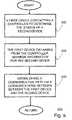
- FIG. 5is a flow chart of steps performed in accordance with one embodiment of the present claimed invention.
- the system and method of the present inventionprovides information regarding a dynamic IP network address associated with a first device (e.g., a server, PC, NAT, etc.) to a second device (e.g., a router or NAT) with minimal or no manual configuration of the second device.
- a first network deviceestablishes its own dynamic IP network address via a secondary circuit or channel (e.g. a circuit switched network) and utilizes a primary circuit or channel (e.g. the internet) to register its dynamic IP network address with a dynamic address network configuration system (controller) and to participate in principal network communications.
- a secondary circuit or channele.g. a circuit switched network
- a primary circuit or channele.g. the internet
- a first network devicesuch as a PC establishes its own dynamic IP network address by communicating with an ISP over a D-channel of an ISDN connection and then communicates with a dynamic address network configuration system or other devices via circuit switched calls on a B-channel.
- a dynamic address network configuration system of the present inventiontracks dynamic network addresses assigned to devices participating in a network and provides assigned dynamic network address information to devices that request it.
- FIG. 1Ais block diagram illustrating dynamic network address minimal configuration system 100 .
- Dynamic network address minimal configuration system 100comprises a first device, device A 110 , a second device, device B 120 , a controller hereinafter referred to as a dynamic network address registration system/controller 130 and communication network 150 (also referred to as network 150 ).
- Network 150is coupled to first device A 110 , second device B 120 and dynamic network address registration system/controller 130 .
- Device A 110 and Device B 120are devices used to facilitate interaction and communications via network 150 (e.g., a personal computer, NAT, router, etc.).
- network 150includes primary and secondary communication circuits or channels (e.g. a circuit switched network and also e.g. the internet) and allows communication paths between devices coupled to network 150 to be established thereon.
- Dynamic network address registration system/controller 130stores information regarding the assignment of dynamic network addresses to devices.
- Dynamic network address minimal configuration system 100provides information regarding the assignment of a dynamic network address to devices coupled to dynamic network address minimal configuration system 100 and facilitates the automatic configuration of network components with minimal manual intervention.
- device A 110utilizes a secondary communications circuit or channel to access network 150 and obtains a dynamic network address.
- Device A 110utilizes a primary communication circuit or channel to establish communications with dynamic network address registration system/controller 130 and forwards information regarding the dynamic network address assigned to device A 110 .
- Dynamic network address registration system/controller 130stores information regarding the association of device A 110 and the dynamic network address assigned to device A 110 .
- Dynamic network address registration system/controller 130also transmits to device A 110 a network address associated with dynamic network address registration system/controller 130 .
- Device B 120also utilizes a secondary circuit or channel to establish a dynamic network address and uses a primary circuit or channel to transmit to dynamic network address registration system/controller 130 information regarding the association between device B 120 and its dynamic network address. Then device A 110 and device B 120 utilize dynamic network address registration system/controller 130 to facilitate automatic downloading of information regarding each other's assigned dynamic network address and automatic configuration of network components.
- FIG. 1Bis a block diagram illustrating one embodiment of dynamic network address registration system/controller 130 .
- dynamic network address registration system/controller 130is included in an intermediate device coupled to a network.
- Dynamic network address registration system/controller 130comprises means for coupling to a communications network, for example, communications port 131 ; means for storing address information of a first device therein and means for storing address information of a second device therein, for example, communication frame analysis component 132 ; and means for providing the address information of the second device to the first device such that a communication path can be efficiently established between the first device and the second device via the communications network, for example, dynamic address mapping component 133 .
- Communications port 131is coupled to communication frame analysis component 132 and dynamic address mapping component 133 .
- Communication frame analysis component 132is coupled to dynamic address mapping component 133 .
- the components of dynamic network address registration system/controller 130interact with one another to facilitate communications with devices having dynamic addresses.
- Communications port 131transmits and receives communication frames to and from devices coupled to dynamic network address registration system/controller 130 .
- communications port 131transmits and receives communication frames via multiple communication circuits or channels including a primary and a secondary communications circuit or channel.
- communications port 131transmits communication frames via different networks including the Internet or a direct modem switched circuit communication link that are used for primary communication circuits or secondary communication circuits.
- Communication frame analysis component 132is adapted to analyze information included in a communication frame.
- Communication frame analysis component 132examines the information included in a communication frame and ascertains the name of a principal destination device.
- the principal destination deviceis the desired device that a user ultimately wants to communicate with and has been assigned a dynamic network address.
- Communication frame analysis component 132determines if the communication frame is requesting information regarding an assigned dynamic network address or forwarding a dynamic network address for registration in dynamic network address registration system/controller 130 . If the communication frame is requesting information regarding an assigned dynamic network address, dynamic network address registration system/controller 130 provides the information to the requesting device.
- communication frame analysis component 132issues an instruction to dynamic address mapping component 140 to map a dynamic address to the name of a particular principal destination device if a communication frame.
- Dynamic address mapping component 133is adapted to map a dynamic network address to a device name. Communication frames forwarding a dynamic network address for inclusion in dynamic address mapping component 140 also include information regarding the name of a destination device that has been assigned the dynamic network address. Dynamic address mapping component 140 retains a record of the association between the named device and dynamic IP network address. In one embodiment of the present invention dynamic address mapping component 140 disregards a prior association if the prior dynamic IP network address or device name is presented to dynamic address mapping component 140 in association with a new device or new dynamic IP network address. In one embodiment the dynamic address mapping component 140 includes a directory name service (DNS) that provides a mapping of designated names in a uniform resource locating (URL) protocol to dynamic IP network addresses.
- DNSdirectory name service
- dynamic network address minimal configuration system 100is described in terms of one embodiment of the present invention, it should be appreciated the present invention is also well suited for use in other configuration.
- dynamic network address minimal configuration system 100is implemented in networks comprising a LAN and a WAN.
- dynamic network address minimal configuration system 100is utilized to establish a virtual private network (VPN) via the Internet.
- VPNvirtual private network
- tracking dynamic addresses by dynamic network address minimal configuration system 100is controlled by software.
- the present inventionis implemented in combinations of software, hardware and firmware which automatically track dynamic address assignments and forwards the relevant dynamic address information to and from devices coupled to dynamic network address minimal configuration system 100 .
- FIG. 2is a block diagram illustrating dynamic network address minimal configuration system 200 , one embodiment of the present invention.
- Network address minimal configuration system 200comprises NAT 215 , router 291 , PC 211 , PC 212 , PC 213 , PC 240 , PC 293 , server 292 , dynamic network address registration system/controller 130 and network 281 .
- NAT 215is coupled to PC 211 , PC 212 , and PC 213 in a configuration that comprises a first LAN in a home.
- Router 291is coupled to PC 291 and Server 292 in an arrangement that comprises a second LAN at a business.
- Internet web 281is coupled to NAT 215 , router 291 , PC 240 and dynamic network address registration system/controller 130 in a configuration that comprises a WAN.
- Each device coupled to the WANhas access at its location to at least one ISDN basic rate interface (BRI) for connectivity to the wide area network Internet Web 281 and an always on dynamic ISDN (AODI) feature is supported for each of these BRIs.
- BRIISDN basic rate interface
- AODIalways on dynamic ISDN
- AODIis a feature of ISDN that uses an ISDN signaling channel (e.g., D-channel) to have a low speed connection that is active (e.g., to an ISP).
- Devices coupled to network address minimal configuration system 200utilize communication paths of network address minimal configuration system 200 and the present invention to establish communications to devices that are assigned dynamic IP network addresses.
- Dynamic network address registration system/controller 130tracks the assignment of dynamic IP network addresses to devices included in network address minimal configuration system 200 .
- PC 211 , PC 212 , PC 213 , PC 240 , and PC 291permit users to interact with devices coupled to network address minimal configuration system 200 .
- Server 292is a system that provides services including database access, network management, and centralized file storage. Router 291 router provides traffic control and filtering functions between communication points on both sides of router 291 .
- NAT 215is associated with a primary LAN including PC 211 , 212 and 213 and facilitates the transmission of communications from the primary LAN to internet web 281 by translating between a primary LAN IP network address for a device and an internet web 281 network address.
- Internet Web 281facilitates communications between devices coupled to it.
- Router 291 and NAT 215also maintain a list of the directory numbers corresponding to other devices coupled to network address minimal configuration system 200 , such as dynamic network address registration system/controller 130 . Maintaining directory numbers in router 291 and NAT 215 enables circuit switched calls to be placed to other devices included in network address minimal configuration system 200 . In one embodiment of router 291 and NAT 215 , numbers corresponding to other devices coupled to network address minimal configuration system 200 are entered individually via a management interface and in another embodiment they are downloaded from a central management station (not shown).
- Router 291 and NAT 215make an AODI connection to their respective local ISP over a D channel when they initially come on line and obtain assignment of a dynamic network address.
- local D-channel connections of network address minimal configuration system 200are relatively low cost connections.
- Router 291 and NAT 215then call up the dynamic network address registration system/controller 130 via circuit switched calls (e.g., over a ISDN B-channel). Utilizing switched circuit calls, router 291 and NAT 215 register their dynamic IP network address (corresponding to its AODI connection) with dynamic network address registration system/controller 130 .
- the IP network address of dynamic network address registration system/controller 130is actually assigned via an AODI link to a router that processes communications to and from a site at which dynamic network address registration system/controller 130 is located. After obtaining the appropriate dynamic IP network address information router 291 and NAT 215 tear down the circuit switched calls with dynamic network address registration system/controller 130 .
- router 291 and NAT 215tear down the circuit switched calls with dynamic network address registration system/controller 130 , they establish VPN connections with dynamic network address registration system/controller 130 via respective local ISPs for router 291 and NAT 215 .
- router 291 and NAT 215are able to avoid long distance toll charges for communications with dynamic network address registration system/controller 130 .
- Router 291 and NAT 215use the VPN across the Internet to communicate with the dynamic network address registration system/controller 130 's server or router and obtain a list of other devices (e.g., routers or NATs) that have registered with the dynamic network address registration system/controller 130 , as well as dynamic IP network addresses associated with such devices.
- router 291 and NAT 215periodically poll the dynamic network address registration system/controller 130 via their VPN connection to dynamic IP network address information and find out if any new devices have registered.
- devicese.g., a router or NAT
- devices at each site in network address minimal configuration system 200is able to establish VPN connections with other devices to exchange information (e.g., router control data, user data, etc.).
- these VPN connectionsare established via D channels or B channels if there is a lot of information to be communicated. As more communication traffic is involved the capacity of the call is increased by including B-channels and using multi-link PPP across the D-channel and the B-channel.
- Devices included in network address minimal configuration system 200also monitor the status of their communications with the dynamic network address registration system/controller 130 . If communications are lost between devices included in network address minimal configuration system 200 (e.g., a router or NAT) and dynamic network address registration system/controller 130 , after a predetermined time the device (e.g., router or NAT) will attempt to make a circuit switched call to the dynamic network address registration system/controller 130 . In one embodiment, this permits VPN recovery in situations when the AODI connection between dynamic network address registration system/controller 130 and its respective ISP goes down and comes back up, resulting in the assignment of a new dynamic IP network address to dynamic network address registration system/controller 130 .
- devices included in network address minimal configuration system 200e.g., a router or NAT
- the devicee.g., router or NAT
- dynamic network address registration system/controller 130contacts each of the previously registered devices (e.g., routers and NATs) included in network address minimal configuration system 200 using VPN connections across the Internet to inform the other devices (e.g., routers and NATs) of the new IP network address assigned to dynamic network address registration system/controller 130 .
- devicese.g., routers and NATs
- Dynamic IP network address mapping table 300comprises multiple network rows arranged in two columns including a first column 310 and a second column 320 . Entries in a first column 310 indicate the name of a particular device. Data in the second column 320 designates dynamic IP network address that is currently assigned to the device named in the same row in column 310 . Information in dynamic IP network address mapping table 300 is utilized by NAT 215 and router 291 during their network communication operations.
- Dynamic network address registration system/controller 130determines if server 292 is listed as an entry in the first column 310 of dynamic IP network address mapping table 300 and if there is a match transmits the dynamic IP network address indicated in the same row of dynamic IP network address mapping table 300 to PC 211 .
- Dynamic IP network address mapping table 300is automatically constructed by dynamic network address registration system/controller 130 .
- FIG. 4is a flow chart of dynamic network address configuration method 400 one embodiment of the present invention.
- Dynamic network address configuration method 400facilitates identification of dynamic addresses for use in configuring network devices with minimal manual input.
- dynamic network address configuration method 400establishes dynamic network addresses via a secondary communications circuit (e.g., a secondary channel) and a VPN via a primary communications circuit (e.g., a primary channel).
- dynamic network address configuration method 400obtains a dynamic network address via a secondary communications circuit.
- a network deviceestablishes a network communication link via a secondary circuit and is assigned a dynamic network address.
- a PCestablishes an Internet connection with an ISP provider via a D channel of an ISDN and is assigned a dynamic network IP address.
- Information regarding the assigned dynamic network addressis transmitted to a network address registration system in Step 420 .
- the information regarding the assigned dynamic network addressis transmitted via a primary communication system.
- a PCtransmits information regarding its assigned dynamic network address via a B channel of and ISDN.
- Information regarding the assigned dynamic network address and it association with a network deviceis stored in the dynamic network address registration system.
- Step 430 of dynamic network address configuration method 400information regarding the assignment of a dynamic network address is communicated from the network address registration system to network devices.
- a network address associated with a dynamic network address registration system and a dynamic network address associated with a particular network deviceis forwarded to another network device in an Internet session established vi a primary circuit (e.g., a B channel of a ISDN interface).
- dynamic network address configuration method 400automatically polls the dynamic network address registration system to determine if there are updates to information regarding a registered dynamic address.
- the present inventionis a system and method that provides network source devices with information regarding a dynamic address assigned to a network destination device.
- the system and methodexpedites the establishment of network sessions and supplies dynamic destination address information automatically with a minimum amount of manual network administration intervention.
- the system and methodreduces the amount of user configuration input and interaction required to setup a NAT or router for participation in a VPN session.
- the system and methodfacilitates efficient automatic configuration of NATs and routers with dynamic destination network addresses and simplifies connection of communication paths that transport communication frames over one or more networks.
- a flow chart 500 of steps performed in accordance with one embodiment of the present inventionis shown. The steps of FIG. 5 will be discussed in conjunction with the detailed description set forth above and with the features of FIGS. 1A , 1 B, 2 , 3 , and 4 .
- a first devicee.g. device A 110
- a controllere.g. dynamic network address registration system/controller 130
- the first deviceobtains, from the controller, via a second communications network (e.g. a circuit switched network) the information as to whether or not the second device is coupled to the first communications network (e.g. the internet).
- a second communications networke.g. a circuit switched network
- the first devicedetermines from the controller that the second device is not coupled to the first communications network (e.g. the internet).
- the first deviceinstructs the second device, via a second communications network (e.g. a circuit switched network), to couple to the first communications network and report the second device's dynamic address information to the controller.
- This instruction for the second deviceis accomplished briefly thereby minimizing the costs associated with the use of the second communications network.
- the first devicethen couples to the first communications network, to the controller, and subsequently to the second device.
- the controlleris aware of and is able to store the dynamic address information of the first device and the dynamic address information of the second device.
- the present embodimentallows for the efficient establishment of communication path between the first device and the second device via the first communications network.
- the present embodimentallows for the establishment of the communication path without requiring that the first device and the second device have a static address.
- the present embodimentdoes not require communication paths to be established using circuit switched networks for prolonged periods of time.
- the first devicedetermines from the controller that the second device is not coupled to the first communications network (e.g. the internet).
- the controllerinstructs the second device, via a second communications network (e.g. a circuit switched network), to couple to the first communications network and report the second device's dynamic address information to the controller.
- This instruction for the second deviceis accomplished briefly thereby minimizing the costs associated with the use of the second communications network.
- the first devicethen couples to the first communications network, to the controller, and subsequently to the second device.
- the controlleris aware of and is able to store the dynamic address information of the first device and the dynamic address information of the second device.
- the present embodimentallows for the efficient establishment of communication path between the first device and the second device via the first communications network.
- the present embodimentallows for the establishment of the communication path without requiring that the first device and the second device have a static address.
- the present embodimentdoes not require communication paths to be established using circuit switched networks for prolonged periods of time.
- the first deviceobtains, from the controller, address information for the second device. That is, as the second device couples to the communications network, the controller is aware of and is able to store the dynamic address information of the second device. As mentioned above, in the present embodiment, the first device also provides the controller with the dynamic address information of the first device.
- the present inventionthen establishes a communication path via a communications network (e.g. the internet) between the first device and the second device.
- a communications networke.g. the internet
- the controllerenable efficient establishment of the communication path between the first device and the second device, via the communications network, without requiring the first device and the second device to have static addresses.
- the controllerenables establishment of a virtual private network (VPN) between the first device and the second device via the communications network.
- VPNvirtual private network
- the present inventionprovides a method and system for efficiently establishing a communication path between a first device and a second device via a communications network.
- the present inventionfurther provides a method and system for efficiently establishing a communication path between a first device and a second device wherein the system and method accomplishes the above-listed achievement and does not require communication paths to be established using circuit switched networks for prolonged periods of time.
- the present inventionalso provides a method and system for efficiently establishing a communication path between a first device and a second device wherein the system and method accomplishes the above-listed achievements and does not require the use of static addresses.
Landscapes
- Engineering & Computer Science (AREA)
- Computer Networks & Wireless Communication (AREA)
- Signal Processing (AREA)
- Computer Security & Cryptography (AREA)
- Data Exchanges In Wide-Area Networks (AREA)
Abstract
Description
Claims (17)
Priority Applications (1)
| Application Number | Priority Date | Filing Date | Title |
|---|---|---|---|
| US09/322,114US7275113B1 (en) | 1999-05-27 | 1999-05-27 | Dynamic network address configuration system and method |
Applications Claiming Priority (1)
| Application Number | Priority Date | Filing Date | Title |
|---|---|---|---|
| US09/322,114US7275113B1 (en) | 1999-05-27 | 1999-05-27 | Dynamic network address configuration system and method |
Publications (1)
| Publication Number | Publication Date |
|---|---|
| US7275113B1true US7275113B1 (en) | 2007-09-25 |
Family
ID=38520095
Family Applications (1)
| Application Number | Title | Priority Date | Filing Date |
|---|---|---|---|
| US09/322,114Expired - LifetimeUS7275113B1 (en) | 1999-05-27 | 1999-05-27 | Dynamic network address configuration system and method |
Country Status (1)
| Country | Link |
|---|---|
| US (1) | US7275113B1 (en) |
Cited By (15)
| Publication number | Priority date | Publication date | Assignee | Title |
|---|---|---|---|---|
| US20050120240A1 (en)* | 2003-12-01 | 2005-06-02 | Gary Kiwimagi | Secure authenticated network connections |
| US20050220099A1 (en)* | 2004-03-30 | 2005-10-06 | Canon Kabushiki Kaisha | Packet relay apparatus and control method for data relay apparatus |
| US20060067321A1 (en)* | 2004-09-27 | 2006-03-30 | Sou Satou | Subscriber line accommodation apparatus and packet filtering method |
| US20060087941A1 (en)* | 2004-09-10 | 2006-04-27 | Michael Obradovich | System and method for audio and video portable publishing system |
| US20080222416A1 (en)* | 2003-12-01 | 2008-09-11 | Gary Kiwimagi | Secure Network Connection |
| US20090327414A1 (en)* | 2004-01-28 | 2009-12-31 | I2 Telecom International, Inc. | System and method of binding a client to a server |
| US7752329B1 (en)* | 2002-10-31 | 2010-07-06 | Aol Inc. | Migrating configuration information based on user identity information |
| US20100315975A1 (en)* | 2006-05-30 | 2010-12-16 | Insightix Ltd. | Method and system for determining physical connectivity in a dynamic network |
| US8843643B2 (en) | 1998-10-30 | 2014-09-23 | Virnetx, Inc. | System and method employing an agile network protocol for secure communications using secure domain names |
| US8874771B2 (en) | 1998-10-30 | 2014-10-28 | Virnetx, Inc. | Agile network protocol for secure communications with assured system availability |
| US8943201B2 (en) | 1998-10-30 | 2015-01-27 | Virnetx, Inc. | Method for establishing encrypted channel |
| US20150261237A1 (en)* | 2012-09-27 | 2015-09-17 | Kyocera Corporation | Management method, control apparatus, and communication processing apparatus |
| US20170201487A1 (en)* | 2009-08-13 | 2017-07-13 | Qualcomm Incorporated | Location determination during network address lookup |
| US9860283B2 (en) | 1998-10-30 | 2018-01-02 | Virnetx, Inc. | Agile network protocol for secure video communications with assured system availability |
| US10511573B2 (en) | 1998-10-30 | 2019-12-17 | Virnetx, Inc. | Agile network protocol for secure communications using secure domain names |
Citations (25)
| Publication number | Priority date | Publication date | Assignee | Title |
|---|---|---|---|---|
| US5095480A (en)* | 1989-06-16 | 1992-03-10 | Fenner Peter R | Message routing system for shared communication media networks |
| US5473599A (en)* | 1994-04-22 | 1995-12-05 | Cisco Systems, Incorporated | Standby router protocol |
| US5677910A (en)* | 1992-08-07 | 1997-10-14 | Plaintree Systems Inc. | High performance two-port transport LAN bridge |
| US5796944A (en)* | 1995-07-12 | 1998-08-18 | 3Com Corporation | Apparatus and method for processing data frames in an internetworking device |
| US5915097A (en)* | 1996-08-14 | 1999-06-22 | Winbond Electronics Corporation | Method and apparatus for data storage and search in an address table of an ethernet switch |
| US5920699A (en)* | 1996-11-07 | 1999-07-06 | Hewlett-Packard Company | Broadcast isolation and level 3 network switch |
| US5983350A (en)* | 1996-09-18 | 1999-11-09 | Secure Computing Corporation | Secure firewall supporting different levels of authentication based on address or encryption status |
| US6009469A (en)* | 1995-09-25 | 1999-12-28 | Netspeak Corporation | Graphic user interface for internet telephony application |
| US6012088A (en)* | 1996-12-10 | 2000-01-04 | International Business Machines Corporation | Automatic configuration for internet access device |
| US6023724A (en)* | 1997-09-26 | 2000-02-08 | 3Com Corporation | Apparatus and methods for use therein for an ISDN LAN modem that displays fault information to local hosts through interception of host DNS request messages |
| US6085238A (en)* | 1996-04-23 | 2000-07-04 | Matsushita Electric Works, Ltd. | Virtual LAN system |
| US6112232A (en)* | 1998-01-27 | 2000-08-29 | Phasecom Ltd. | Data communication device for CATV networks |
| US6151497A (en)* | 1998-02-12 | 2000-11-21 | Motorola, Inc. | Satellite based high bandwidth data broadcast |
| US6195691B1 (en)* | 1996-09-17 | 2001-02-27 | National Systems Corporation | Method and apparatus for creating and using dynamic universal resource locators |
| US6195705B1 (en)* | 1998-06-30 | 2001-02-27 | Cisco Technology, Inc. | Mobile IP mobility agent standby protocol |
| US6256635B1 (en)* | 1998-05-08 | 2001-07-03 | Apple Computer, Inc. | Method and apparatus for configuring a computer using scripting |
| US20010006519A1 (en)* | 1997-03-06 | 2001-07-05 | Bell Atlantic Network Services, Inc. | Automatic called party locator over internet |
| US20020035594A1 (en)* | 1998-12-28 | 2002-03-21 | Christian Dreke | Method for distributing and maintaining network presence information |
| US6430698B1 (en)* | 1998-10-05 | 2002-08-06 | Nortel Networks Limited | Virtual distributed home agent protocol |
| US6430595B1 (en)* | 1999-05-20 | 2002-08-06 | Cisco Technology, Inc. | Method and apparatus for establishing a database used for correlating information gathered via SNMP |
| US6502131B1 (en)* | 1997-05-27 | 2002-12-31 | Novell, Inc. | Directory enabled policy management tool for intelligent traffic management |
| US20030097430A1 (en)* | 1997-08-20 | 2003-05-22 | Ryuichi Matsukura | Computer network system and portable computer |
| US6571282B1 (en)* | 1999-08-31 | 2003-05-27 | Accenture Llp | Block-based communication in a communication services patterns environment |
| US6684336B1 (en)* | 1999-04-30 | 2004-01-27 | Hewlett-Packard Development Company, L.P. | Verification by target end system of intended data transfer operation |
| US6816903B1 (en)* | 1997-05-27 | 2004-11-09 | Novell, Inc. | Directory enabled policy management tool for intelligent traffic management |
- 1999
- 1999-05-27USUS09/322,114patent/US7275113B1/ennot_activeExpired - Lifetime
Patent Citations (25)
| Publication number | Priority date | Publication date | Assignee | Title |
|---|---|---|---|---|
| US5095480A (en)* | 1989-06-16 | 1992-03-10 | Fenner Peter R | Message routing system for shared communication media networks |
| US5677910A (en)* | 1992-08-07 | 1997-10-14 | Plaintree Systems Inc. | High performance two-port transport LAN bridge |
| US5473599A (en)* | 1994-04-22 | 1995-12-05 | Cisco Systems, Incorporated | Standby router protocol |
| US5796944A (en)* | 1995-07-12 | 1998-08-18 | 3Com Corporation | Apparatus and method for processing data frames in an internetworking device |
| US6009469A (en)* | 1995-09-25 | 1999-12-28 | Netspeak Corporation | Graphic user interface for internet telephony application |
| US6085238A (en)* | 1996-04-23 | 2000-07-04 | Matsushita Electric Works, Ltd. | Virtual LAN system |
| US5915097A (en)* | 1996-08-14 | 1999-06-22 | Winbond Electronics Corporation | Method and apparatus for data storage and search in an address table of an ethernet switch |
| US6195691B1 (en)* | 1996-09-17 | 2001-02-27 | National Systems Corporation | Method and apparatus for creating and using dynamic universal resource locators |
| US5983350A (en)* | 1996-09-18 | 1999-11-09 | Secure Computing Corporation | Secure firewall supporting different levels of authentication based on address or encryption status |
| US5920699A (en)* | 1996-11-07 | 1999-07-06 | Hewlett-Packard Company | Broadcast isolation and level 3 network switch |
| US6012088A (en)* | 1996-12-10 | 2000-01-04 | International Business Machines Corporation | Automatic configuration for internet access device |
| US20010006519A1 (en)* | 1997-03-06 | 2001-07-05 | Bell Atlantic Network Services, Inc. | Automatic called party locator over internet |
| US6502131B1 (en)* | 1997-05-27 | 2002-12-31 | Novell, Inc. | Directory enabled policy management tool for intelligent traffic management |
| US6816903B1 (en)* | 1997-05-27 | 2004-11-09 | Novell, Inc. | Directory enabled policy management tool for intelligent traffic management |
| US20030097430A1 (en)* | 1997-08-20 | 2003-05-22 | Ryuichi Matsukura | Computer network system and portable computer |
| US6023724A (en)* | 1997-09-26 | 2000-02-08 | 3Com Corporation | Apparatus and methods for use therein for an ISDN LAN modem that displays fault information to local hosts through interception of host DNS request messages |
| US6112232A (en)* | 1998-01-27 | 2000-08-29 | Phasecom Ltd. | Data communication device for CATV networks |
| US6151497A (en)* | 1998-02-12 | 2000-11-21 | Motorola, Inc. | Satellite based high bandwidth data broadcast |
| US6256635B1 (en)* | 1998-05-08 | 2001-07-03 | Apple Computer, Inc. | Method and apparatus for configuring a computer using scripting |
| US6195705B1 (en)* | 1998-06-30 | 2001-02-27 | Cisco Technology, Inc. | Mobile IP mobility agent standby protocol |
| US6430698B1 (en)* | 1998-10-05 | 2002-08-06 | Nortel Networks Limited | Virtual distributed home agent protocol |
| US20020035594A1 (en)* | 1998-12-28 | 2002-03-21 | Christian Dreke | Method for distributing and maintaining network presence information |
| US6684336B1 (en)* | 1999-04-30 | 2004-01-27 | Hewlett-Packard Development Company, L.P. | Verification by target end system of intended data transfer operation |
| US6430595B1 (en)* | 1999-05-20 | 2002-08-06 | Cisco Technology, Inc. | Method and apparatus for establishing a database used for correlating information gathered via SNMP |
| US6571282B1 (en)* | 1999-08-31 | 2003-05-27 | Accenture Llp | Block-based communication in a communication services patterns environment |
Non-Patent Citations (4)
| Title |
|---|
| ATM on Linux-The 3rd year-Werner Almesberger Werner (1997) ast21.csis.hku.hk/download/atm/atm<SUB>-</SUB>3rd.ps.gz.* |
| RAT: A Quick (And Dirty?) Push for Mobility Suppport-Singh, Tay, Teo, Yeow (1999) www.research.att.com/conf/wmcsa99/papers/singh.ps.gz.* |
| Terao et al, A Shared Secured Server for Multiple Closed Networks, IEEE Feb. 1999.* |
| VIP: A Protocol Providing Host Mobility-Teraoka, Uehara, Sunahara, Murai (1994) www.cosc.canterbury.ac.nz/~hpark/academic/research/papers/VIP/teraoka94.ps.* |
Cited By (41)
| Publication number | Priority date | Publication date | Assignee | Title |
|---|---|---|---|---|
| US9386000B2 (en) | 1998-10-30 | 2016-07-05 | Virnetx, Inc. | System and method for establishing a communication link |
| US9038163B2 (en) | 1998-10-30 | 2015-05-19 | Virnetx, Inc. | Systems and methods for connecting network devices over communication network |
| US10511573B2 (en) | 1998-10-30 | 2019-12-17 | Virnetx, Inc. | Agile network protocol for secure communications using secure domain names |
| US10187387B2 (en) | 1998-10-30 | 2019-01-22 | Virnetx, Inc. | Method for establishing connection between devices |
| US9967240B2 (en) | 1998-10-30 | 2018-05-08 | Virnetx, Inc. | Agile network protocol for secure communications using secure domain names |
| US9860283B2 (en) | 1998-10-30 | 2018-01-02 | Virnetx, Inc. | Agile network protocol for secure video communications with assured system availability |
| US9819649B2 (en) | 1998-10-30 | 2017-11-14 | Virnetx, Inc. | System and method employing an agile network protocol for secure communications using secure domain names |
| US9479426B2 (en) | 1998-10-30 | 2016-10-25 | Virnetz, Inc. | Agile network protocol for secure communications with assured system availability |
| US9413766B2 (en) | 1998-10-30 | 2016-08-09 | Virnetx, Inc. | Method for establishing connection between devices |
| US9374346B2 (en) | 1998-10-30 | 2016-06-21 | Virnetx, Inc. | Agile network protocol for secure communications using secure domain names |
| US9100375B2 (en) | 1998-10-30 | 2015-08-04 | Virnetx, Inc. | System and method employing an agile network protocol for secure communications using secure domain names |
| US8943201B2 (en) | 1998-10-30 | 2015-01-27 | Virnetx, Inc. | Method for establishing encrypted channel |
| US9094399B2 (en) | 1998-10-30 | 2015-07-28 | Virnetx, Inc. | Method for establishing secure communication link between computers of virtual private network |
| US9077695B2 (en) | 1998-10-30 | 2015-07-07 | Virnetx, Inc. | System and method for establishing an encrypted communication link based on IP address lookup requests |
| US9077694B2 (en) | 1998-10-30 | 2015-07-07 | Virnetx, Inc. | Agile network protocol for secure communications using secure domain names |
| US8843643B2 (en) | 1998-10-30 | 2014-09-23 | Virnetx, Inc. | System and method employing an agile network protocol for secure communications using secure domain names |
| US8850009B2 (en) | 1998-10-30 | 2014-09-30 | Virnetx, Inc. | System and method employing an agile network protocol for secure communications using secure domain names |
| US8868705B2 (en) | 1998-10-30 | 2014-10-21 | Virnetx, Inc. | Agile network protocol for secure communications using secure domain names |
| US8874771B2 (en) | 1998-10-30 | 2014-10-28 | Virnetx, Inc. | Agile network protocol for secure communications with assured system availability |
| US8904516B2 (en) | 1998-10-30 | 2014-12-02 | Virnetx, Inc. | System and method employing an agile network protocol for secure communications using secure domain names |
| US9037713B2 (en) | 1998-10-30 | 2015-05-19 | Virnetx, Inc. | Agile network protocol for secure communications using secure domain names |
| US9027115B2 (en) | 1998-10-30 | 2015-05-05 | Virnetx, Inc. | System and method for using a registered name to connect network devices with a link that uses encryption |
| US8275900B2 (en)* | 2002-10-31 | 2012-09-25 | Aol Inc. | Migrating configuration information based on user identity information |
| US20100257584A1 (en)* | 2002-10-31 | 2010-10-07 | Aol Inc. | Migrating Configuration Information Based on User Identity Information |
| US9553738B2 (en)* | 2002-10-31 | 2017-01-24 | Aol Inc. | Migrating configuration information based on user identity information |
| US7752329B1 (en)* | 2002-10-31 | 2010-07-06 | Aol Inc. | Migrating configuration information based on user identity information |
| US20130007871A1 (en)* | 2002-10-31 | 2013-01-03 | Aol Inc. | Migrating configuration information based on user identity information |
| US20050120240A1 (en)* | 2003-12-01 | 2005-06-02 | Gary Kiwimagi | Secure authenticated network connections |
| US20080222416A1 (en)* | 2003-12-01 | 2008-09-11 | Gary Kiwimagi | Secure Network Connection |
| US20090327414A1 (en)* | 2004-01-28 | 2009-12-31 | I2 Telecom International, Inc. | System and method of binding a client to a server |
| US9401974B2 (en) | 2004-01-28 | 2016-07-26 | Upland Software Iii, Llc | System and method of binding a client to a server |
| US8606874B2 (en)* | 2004-01-28 | 2013-12-10 | Hipcricket, Inc. | System and method of binding a client to a server |
| US20050220099A1 (en)* | 2004-03-30 | 2005-10-06 | Canon Kabushiki Kaisha | Packet relay apparatus and control method for data relay apparatus |
| US7720057B2 (en)* | 2004-03-30 | 2010-05-18 | Canon Kabushiki Kaisha | Packet relay apparatus and control method for data relay apparatus |
| US20060087941A1 (en)* | 2004-09-10 | 2006-04-27 | Michael Obradovich | System and method for audio and video portable publishing system |
| US20060067321A1 (en)* | 2004-09-27 | 2006-03-30 | Sou Satou | Subscriber line accommodation apparatus and packet filtering method |
| US7680106B2 (en)* | 2004-09-27 | 2010-03-16 | Nec Corporation | Subscriber line accommodation apparatus and packet filtering method |
| US20100315975A1 (en)* | 2006-05-30 | 2010-12-16 | Insightix Ltd. | Method and system for determining physical connectivity in a dynamic network |
| US8811224B2 (en)* | 2006-05-30 | 2014-08-19 | McAfee Ireland Holdings, Limited | Method and system for determining physical connectivity in a dynamic network |
| US20170201487A1 (en)* | 2009-08-13 | 2017-07-13 | Qualcomm Incorporated | Location determination during network address lookup |
| US20150261237A1 (en)* | 2012-09-27 | 2015-09-17 | Kyocera Corporation | Management method, control apparatus, and communication processing apparatus |
Similar Documents
| Publication | Publication Date | Title |
|---|---|---|
| US7275113B1 (en) | Dynamic network address configuration system and method | |
| US7843923B2 (en) | Methods and apparatus for determining the port and/or physical location of an IP device and for using that information | |
| US9705846B2 (en) | Methods and apparatus for providing high speed connectivity to a hotel environment | |
| DE69919999T2 (en) | Method and method for supporting wireless transmission within an Internet network | |
| US6829239B1 (en) | Apparatus and methods for determining the correct workstation within a LAN for a LAN modem to route a packet | |
| US7257837B2 (en) | Firewall penetration system and method for real time media communications | |
| US7836160B2 (en) | Methods and apparatus for wiretapping IP-based telephone lines | |
| US5166931A (en) | Communications network dynamic addressing arrangement | |
| JP2786121B2 (en) | LAN connection router | |
| EP1017206B1 (en) | Method and apparatus for connecting a home network to the internet | |
| CN100401714C (en) | Method for automatically configuring a communication device | |
| US20040085914A1 (en) | Large-scale, fault-tolerant audio conferencing in a purely packet-switched network | |
| US20070217408A1 (en) | Address Resolution Device, Address Resolution Method, And Communication System Including The Same | |
| US6542935B1 (en) | Method for obtaining a second address free from association with multiple devices | |
| US20070127461A1 (en) | Router and communication system | |
| CN101141372A (en) | Method and device for management of routing information and data forwarding in access equipment | |
| WO1998051040A1 (en) | Method for managing multicast addresses in an internet protocol (ip) network | |
| JP2004129126A (en) | Address assignment system | |
| US6775277B1 (en) | Methods and systems for processing calls in a packet network using peer call servers | |
| US20030046400A1 (en) | Contacting a destination terminal from an originating terminal via a packet-based communications network | |
| US20040042446A1 (en) | Maintaining routing information in a passive optical network | |
| US20080049765A1 (en) | Method and system for inter working a point-to-point link and a LAN service | |
| US20020126651A1 (en) | Method for providing information, mobile communication system, and communication apparatus | |
| US6819673B1 (en) | Method and system for establishing SNA sessions over wide area networks | |
| JP3155926B2 (en) | Wireless packet transmission equipment |
Legal Events
| Date | Code | Title | Description |
|---|---|---|---|
| AS | Assignment | Owner name:3COM CORPORATION, CALIFORNIA Free format text:ASSIGNMENT OF ASSIGNORS INTEREST;ASSIGNOR:ARAUJO, KENNETH;REEL/FRAME:010012/0951 Effective date:19990527 | |
| STCF | Information on status: patent grant | Free format text:PATENTED CASE | |
| AS | Assignment | Owner name:HEWLETT-PACKARD COMPANY, CALIFORNIA Free format text:MERGER;ASSIGNOR:3COM CORPORATION;REEL/FRAME:024630/0820 Effective date:20100428 | |
| AS | Assignment | Owner name:HEWLETT-PACKARD COMPANY, CALIFORNIA Free format text:CORRECTIVE ASSIGNMENT TO CORRECT THE SEE ATTACHED;ASSIGNOR:3COM CORPORATION;REEL/FRAME:025039/0844 Effective date:20100428 | |
| FPAY | Fee payment | Year of fee payment:4 | |
| AS | Assignment | Owner name:HEWLETT-PACKARD DEVELOPMENT COMPANY, L.P., TEXAS Free format text:ASSIGNMENT OF ASSIGNORS INTEREST;ASSIGNOR:HEWLETT-PACKARD COMPANY;REEL/FRAME:027329/0044 Effective date:20030131 | |
| AS | Assignment | Owner name:HEWLETT-PACKARD DEVELOPMENT COMPANY, L.P., TEXAS Free format text:CORRECTIVE ASSIGNMENT PREVIUOSLY RECORDED ON REEL 027329 FRAME 0001 AND 0044;ASSIGNOR:HEWLETT-PACKARD COMPANY;REEL/FRAME:028911/0846 Effective date:20111010 | |
| FPAY | Fee payment | Year of fee payment:8 | |
| AS | Assignment | Owner name:HEWLETT PACKARD ENTERPRISE DEVELOPMENT LP, TEXAS Free format text:ASSIGNMENT OF ASSIGNORS INTEREST;ASSIGNOR:HEWLETT-PACKARD DEVELOPMENT COMPANY, L.P.;REEL/FRAME:037079/0001 Effective date:20151027 | |
| MAFP | Maintenance fee payment | Free format text:PAYMENT OF MAINTENANCE FEE, 12TH YEAR, LARGE ENTITY (ORIGINAL EVENT CODE: M1553); ENTITY STATUS OF PATENT OWNER: LARGE ENTITY Year of fee payment:12 |