US7274852B1 - Splice tray arrangement - Google Patents
Splice tray arrangementDownload PDFInfo
- Publication number
- US7274852B1 US7274852B1US11/292,782US29278205AUS7274852B1US 7274852 B1US7274852 B1US 7274852B1US 29278205 AUS29278205 AUS 29278205AUS 7274852 B1US7274852 B1US 7274852B1
- Authority
- US
- United States
- Prior art keywords
- splice
- cable
- arrangement
- cables
- base
- Prior art date
- Legal status (The legal status is an assumption and is not a legal conclusion. Google has not performed a legal analysis and makes no representation as to the accuracy of the status listed.)
- Expired - Fee Related
Links
Images


Classifications
- G—PHYSICS
- G02—OPTICS
- G02B—OPTICAL ELEMENTS, SYSTEMS OR APPARATUS
- G02B6/00—Light guides; Structural details of arrangements comprising light guides and other optical elements, e.g. couplings
- G02B6/44—Mechanical structures for providing tensile strength and external protection for fibres, e.g. optical transmission cables
- G02B6/4439—Auxiliary devices
- G02B6/444—Systems or boxes with surplus lengths
- G02B6/4453—Cassettes
- G02B6/4454—Cassettes with splices
Definitions
- This disclosurerelates generally to devices used in the telecommunications industry. More particularly, this disclosure relates to a splice tray used for managing and storing fiber optic cables.
- a wide variety of telecommunication applicationsutilize fiber optic cables, and in turn involve fiber optic cable splicing and fiber optic cable storage. In these applications, care must be taken to avoid unnecessary or excessive bending of the cables. Bending of fiber optic cables can, for example, cause attenuation, loss of signal strength, and sometimes complete loss of signal transmission through the fiber.
- Splice traysare often used to organize and manage fiber optic cables.
- a splice traytypically holds a number of fiber optic cables.
- stranded cablehas a single fiber optic surrounded by an insulator.
- Ribbon cablehas multiple fiber optics surrounded by a matrix and arranged side-by-side in a flat ribbon-like construction.
- Stranded cableis generally circular in cross-section and is relatively small in size (typically about 900 microns in diameter). Because of the small size and configuration of stranded cables, a generous extra amount of each of the stranded cables of a splice tray can be stored around spools in the splice tray. The extra amount of cable, or slack cable, is often provided in the event a portion of the cable needs to be replaced or repaired, for example.
- the needed amount of slack cableis simply un-wound or removed from the spool, the repair completed, and the remaining slack cable re-wound around the spool. Because of the number of other stranded cables in the splice tray, the slack cable of each of the stranded cables most likely crosses over other cables as slack cable is utilized. While a neatly organized and managed cable arrangement is preferred, the relative small size and configuration of stranded cable does permit the cables to cross over one another when stored around spools in the splice tray.
- Extra slack ribbon cable of a ribbon cable splice traycannot be utilized and stored as simply and easily as stranded cable.
- the flat ribbon-like construction of ribbon cablegenerally has a width of 0.125 inches. Because of the width of the flat ribbon cable, ribbon cables cannot cross-over one another, as the combined height of the ribbon cables exceeds the maximum storage height of splice trays.
- the trayincludes a splice holding arrangement that accommodates both stranded splice components and ribbon splice components.
- the trayalso includes a storage arrangement having radius limiting elements that define a number of storage and routing pathways.
- the splice traymay further include routing information formed in the tray to eliminate the need for a separate schematic diagram.
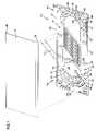
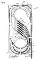
- FIG. 1is an exploded perspective view of one embodiment of a splice tray, according to the principles of the present disclosure, shown in use with stranded cable splice components;
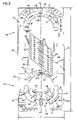
- FIG. 2is an exploded perspective view of the splice tray of FIG. 1 , shown in use with ribbon cable splice components;
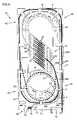
- FIG. 3is a top plan view of the splice tray of FIG. 1 ;
- FIG. 4is a top plan view of the splice tray of FIG. 3 , showing various routing schemes of stranded cable;
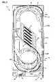
- FIG. 5is a top plan view of the splice tray of FIG. 3 , showing various routing schemes of ribbon cable;
- FIG. 6is a top plan view of the splice tray of FIG. 5 , showing one of many routing schemes of ribbon cable;
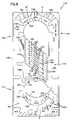
- FIG. 7is a perspective view of another embodiment of a splice tray, according to the principles of the present disclosure.
- FIG. 8is a top plan view of the splice tray of FIG. 7 ;
- FIG. 9is a top plan view, with detail, of the splice tray of FIG. 8 , shown in use with ribbon cable.
- FIGS. 1 and 2illustrate a splice tray 10 having features that are examples of how inventive aspects in accordance with the principles of the present disclosure may be practiced. Preferred features are adapted for promoting cable management by preventing cable attenuation due to excessive cable bending, and providing convenient storage of slack cable for either stranded cable or ribbon cable.
- the splice tray 10 of the present disclosureis used to house spliced fiber optic cables.
- a splice componentcan include, for example, a stranded heat shrink splice component 12 ( FIG. 1 ) used to join single-fiber cables; or a mass fusion splice component 14 ( FIG. 2 ) used to join ribbon cables.
- the splice tray 10 of the present disclosureincludes a splice holding arrangement 16 for holding or retaining the splice components, e.g., 12 , 14 .
- the splice tray 10 of the present disclosureincludes a storage arrangement 20 for storing slack cable.
- the splice tray 10includes a base 22 .
- the base 22 of the splice tray 10is preferably a molded construction.
- the base 22can be molded from common engineering materials including polymers such as polybutylene terephthalate (PBT), polycarbonate (PC), polyethylene ether (PPE), and polystyrene (PS), for example.
- a cover 18is provided.
- the cover 18can be molded or manufactured from similar or different materials than that of the base 22 .
- the splice holding arrangement 16 of the splice tray 10is preferably integrally formed or molded with the base 22 . That is, the splice holding arrangement 16 is not attachable or detachable from the base 22 ; rather, the splice tray 10 is constructed such that the base 22 and the splice holding arrangement 16 are a one-piece unit.
- the base 22 of the splice tray 10includes a generally planar surface 24 having a first end 26 and a second end 28 . Tray sides extend outward from the planar surface 24 . In the illustrated embodiment, the tray sides include two opposing sides 30 , 31 and a side 32 transverse to the two opposing sides 30 , 31 . The transverse side 32 is located at the second end 28 of the planar surface 24 or base 22 . As shown in FIG. 3 , the base 22 has a generally longitudinal dimension L extending between the first end 26 and the second end 28 , and a transverse dimension T extending between the two opposing sides 30 , 31 .
- the sides 30 , 31 , 32 of the splice tray 10are located along a majority of the perimeter of the planar surface 24 and at least partially define an interior 34 ( FIG. 1 ) of the splice tray 10 .
- An open side 36is located at the first end 26 of the base 22 to provide access to the interior 34 .
- the open side 36 or open endfunctions as a cable entry and a cable exit.
- the tray sidesincludes cover attachment structure 37 .
- the cover attachment structure 37includes openings 37 formed in at least one of the opposing sides 30 , 31 of the splice tray 10 .
- the cover attachment structure 37can be formed in the transverse side 32 located at the second end 28 of the splice tray 10 .
- the openings 37 in the illustrated embodimentare constructed to receive mating structure (not shown), such as a rib, located on an inner surface of an edge 38 of the cover 18 .
- the mating structuretypically snap-fits within the openings 37 of the base 22 to at least partially enclose the interior 34 of the splice tray 10 .
- the storage arrangement 20 for storing slack cable of the splice tray 10includes a first radius limiting arrangement 40 and a second radius limiting arrangement 42 .
- the first radius limiting arrangement 40is located adjacent to the first end 26 of the base 22
- the second radius limiting arrangement 42is located adjacent to the second end 28 of the base 22 .
- at least one of the first and second radius limiting arrangements 40 , 42includes a plurality of radius elements that make up the particular arrangement.
- the first radius limiting arrangement 40includes a first plurality of radius elements 44
- the second radius limiting arrangement 42includes a second plurality of radius elements 46 .
- the first and second plurality of radius elements 44 , 46 of the radius limiting arrangements 40 , 42are disposed on the planar surface 24 of the splice tray 10 .
- each of the radius elements 44 , 46is integrally formed or molded on the base 22 of the splice tray 10 .
- each of the radius elements 44 , 46is defined by a curved wall 48 ( FIG. 1 ) that projects outward from the planar surface 24 of the splice tray 10 .
- the projecting wall 48is a molded construction formed on the planar surface 24 ; accordingly, the radius elements 44 , 46 of the radius limiting arrangements 40 , 42 are made of a similar material to that of the base 22 , as previously described.
- the embodiment of the radius elements 44 , 46can take on a number of shapes.
- one of the radius elements 44 (i.e., 88 ) of the first radius limiting arrangement 40is formed as a continuous structure or island, which includes the curved wall 48 that projects from the planar surface 24 .
- another of the radius elements 46 (i.e., 89 ) of the second radius limiting arrangement 42is formed as a continuous structure or island, which includes the curved wall 48 that projects from the planar surface 24 .
- some of the radius elements 44 , 46 (e.g., 81 , 82 ) of the limiting arrangements 40 , 42are simply defined by only the curved wall 48 .
- a number of radius elements 44 , 46 of the first and second radius limiting arrangements 40 , 42are generally positioned in a symmetrical arrangement about a centerline (cl) of the tray 10 .
- the radius limiting arrangements 40 , 42are constructed to limit the bend radius of cables when the cables are wrapped about the radius elements 44 , 46 for storage and/or organizational purposes.
- the curved wall 48 of each of the radius elements 44 , 46 of the limiting arrangements 40 , 42has a radius limiting diameter D of preferably no less than 3.0 inches to provide a minimum bend radius of 1.5 inches; although the disclosed principles can be applied in a variety of sizes and applications depending upon the type of cable stored, for example.
- the radius limiting diameter Dcan be an outer convex diameter or an inner concave diameter.
- the diameters D of each of the radius elements 44 , 46are approximately the same.
- the outer diameter of each of the radius limitersmay be different from one another, but are preferably no less than 3.0 inches.
- the storage arrangement 20 of the present splice trayoffers a variety of storage routing schemes that accommodate varying lengths of cable. That is, the radius elements 44 , 46 of the first and second radius limiting arrangements 40 , 42 define a number of cable pathways that accommodate varying length of cable slack.
- the number of cable pathwaysincludes an outer pathway, a first inner pathway, a second inner pathway, and a number of other pathway configurations made up from pathway segments of the storage arrangement 20 .
- the radius elements 44 , 46 of the first and second radius limiting arrangements 40 , 42include outer radius elements 80 – 83 .
- the outer radius elements 80 – 83define the outer pathway of the tray 10 .
- the outer pathwayis generally the outermost pathway defined between the outer radius elements 80 – 83 of the first and second radius limiting arrangements 44 , 46 , and the sides 30 , 31 , 32 of the tray 10 .
- the outer pathwayincludes a first segment or outer cable loop A defined by the outer radius elements 80 , 81 of the first radius limiting arrangement 40 ; and a second segment or outer cable loop A′ defined by the outer radius elements 82 , 83 of the second radius limiting arrangement 42 .
- the radius elements 44 , 46 of the first and second radius limiting arrangements 40 , 42also include inner radius elements 86 – 89 .
- the inner radius elements 86 – 89 of the radius elements 44 , 46define the first inner pathway of the splice tray 10 .
- the first inner pathwayincludes first, second, and third segments or cable loops, B, B′, B′′.
- the first segment Bis generally defined between the outer radius elements 80 , 81 and the inner radius element 86 of the first radius limiting arrangement 40 .
- the second segment or cable loop B′is generally defined between the outer radius elements 82 , 83 and the inner radius element 89 of the second radius limiting arrangement 42 .
- the third segment or spooling loop B′′is generally defined between the inner radius elements 87 , 88 of the first radius limiting arrangement 40 .
- the radius elements 44 of the first radius limiting arrangement 40also include an inner radius element 94 .
- the inner radius element 94defines the second inner pathway of the storage arrangement 20 .
- the second inner pathwayincludes a segment or inner cable loop C.
- the segment Cis generally defined between the inner radius element 86 and the inner radius element 94 .
- each of the radius elements 44 , 46 of the radius limiting arrangements 40 , 42includes one or more tabs 50 .
- the tabsextend transversely outward from the walls 48 of the radius elements 44 , 46 .
- the tabs 50are located adjacent to a top edge 52 of the wall 48 of each radius element so that a gap G is provided between the tab 50 and the planar surface 24 of the base 22 . Cables are tucked under the tabs 50 and within the gap G during storage.
- the tabs 50help to retain the cables about the radius elements 44 , 46 .
- Side tabs 54are also formed along each of the sides 30 , 31 , 32 of the splice tray 10 for retaining cables within the interior 34 of the tray.
- slots 56are formed in the planar surface 24 opposite each of the tabs 50 , 54 for manufacturing purposes.
- the present cable tray 10further includes corner fillets 66 integrally molded as part of the base 22 .
- the corner fillets 66are provided to prevent cables from pushing into the corners of the splice tray 10 and bending beyond the minimum bend radius of 1.5 inches.
- the splice holding arrangement 16 of the splice tray 10is positioned between the first and second radius limiting arrangements 40 , 42 .
- the splice holding arrangement 16includes a plurality of slots or channels 58 within which the splice components (e.g., 12 , 14 ) are placed and held. As shown in FIG. 3 , the channels 58 run parallel to one another. In the illustrated embodiment, the splice holding arrangement 16 includes twelve parallel channels 58 .
- the channels 58are oriented in a non-perpendicular angle N relative to the longitudinal dimension L of the base 22 . In the illustrated embodiment, the channels 58 are diagonally oriented relative to the longitudinal and transverse dimensions of the base 22 .
- the channels 58 of the splice holding arrangement 16are defined by retaining structure 60 .
- the splice holding arrangement 16and accordingly, the retaining structure 60 are integrally molded or formed on the planar surface 24 of the splice tray 10 .
- the channels 58are also defined by curved fingers 62 , 64 located at opposite ends of the retaining structure 60 of the splice holding arrangement 16 .
- the curved fingers 62 , 64are also integrally molded or formed on the planar surface 24 of the splice tray 10 . Therefore, the retaining structure 60 and the fingers 62 , 64 are made of a similar material to that of the base 22 of the splice tray, as previously described.
- the retaining structure 60 of the splice holding arrangement 16is preferably designed to retain and hold two types of splice components; i.e., the stranded heat shrink splice components 12 (stranded splice component) and the mass fusion splice components 14 (ribbon splice component).
- the retaining structure 60 of the splice holding arrangement 16is designed to hold up to twenty-four stranded splice components 12 (two in each channel 58 ), or up to six ribbon splice components 14 .
- each type of cableincludes a first incoming cable length joined to a second outgoing cable length by a splice component. While referred to as incoming and outgoing cable lengths, it will be appreciated that the terms incoming and outgoing are used for explanatory purposes of the illustrated embodiment and that the nomenclature may be conversely assigned.
- FIG. 4illustrates the splice tray 10 in use with fiber optic stranded cables 90 .
- the stranded cable 90enters and exits through the open side 36 or open end of the splice tray 10 .
- a first incoming length or portion 90 A(represented by a bold, thin line) of the stranded cable 90 enters at an entrance location 68 located at the open end of the splice tray 10 .
- exit location 70At the open end of the tray.
- the entrance location 68can include a number of guides 72 for organizing the incoming cables lengths 90 A. Because the incoming cable lengths 90 A enter adjacent one side 30 of the splice tray and are then routed toward the opposite side 31 of the tray, as will be described in greater detail hereinafter, the guides 72 are curved to prevent the cables from exceeding a minimum bend radius of 1.5 inches.
- the stranded cables 90can be fixed at the particular entering and exiting locations 68 , 70 of the base 22 .
- a slot 74is provided at the entrance location 68 of the splice tray 10 .
- a lancing, tie, or other securing device 76can be placed through the slot 74 and around the guide(s) 72 to tie or secure the cables 90 at the entrance location 68 .
- apertures 78are provided adjacent to the exit location 70 of the splice tray 10 to receive a tie 76 for securing the cables 90 at the exit location 70 .
- the incoming cable length 90 A of each of the cables 90enters at the entrance location 68 and is routed through the first and second radius limiting arrangements 40 , 42 in a counter-clockwise direction.
- the cable length 90 Ais routed around the outer radius element 81 (i.e, within a portion of the first segment A of the outer pathway) of the first radius limiting arrangement 40 in a counter-clockwise direction.
- the cable length 90 Athen runs within the outer pathway adjacent to the side 31 of the splice tray 10 and through the second segment A′ of the outer pathway.
- the first incoming cable length 90 Ais fed through the curved fingers 62 and into one of the channels 58 of the splice holding arrangement 16 .
- a stranded splice component 12is used to join the first incoming cable length 90 A and the second outgoing cable length 90 B to provide a connection therebetween.
- the second outgoing cable length 90 Bexits the curved fingers 64 of the splice holding arrangement 16 and is routed through the first and second radius limiting arrangements 40 , 42 in a clockwise direction. Depending upon the amount of slack desired, the outgoing cable length 90 B can be routed through either the first segment A of the outer pathway or through the first segment B of the first inner pathway.
- the outgoing stranded cable length 90 Bis routed from the splice holding arrangement 16 to the first segment A of the outer pathway of the first radius limiting arrangement 40 , and then directly to the second segment A′ of the outer pathway of the second radius limiting arrangement 42 . From the second segment A′ of the outer pathway, the stranded cable 90 is routed along the side 31 of the tray 10 , and exits the tray at the exit location 70 . As shown in FIG.
- the outgoing stranded cable length 90 Bis routed both inside the incoming stranded cable length 90 A when coming from the splice holding arrangement 16 , and outside of the incoming stranded cable length 90 A when coming from the second outer pathway segment A′, without crossing over the incoming cable length 90 A.
- This routing schemekeeps the incoming and outgoing lengths 90 A, 90 B neatly separated and organized.
- the outgoing stranded cable length 90 Bcan be routed from the splice holding arrangement 16 to the first segment B of the first inner pathway (as represented by dashed lines). From the first segment B of the first inner pathway, the stranded cable 90 can be routed through the third segment B′′ of the radius limiting arrangement 40 .
- the third segment B′′is referred to as the stranded storage segment.
- the radius element 87 that partially defines the stranded storage segment B′′is located in relation to radius element 86 to provide a circular spooling structure.
- the spooling structuredefines a spooling pathway.
- the spooling pathway(segments B, B′′) is located only at one side of the tray, i.e., defined by only the first radius limiting arrangement 40 , as opposed to being defined by both first and second limiting arrangements 40 , 42 (as is the outer pathway, for example).
- the outgoing stranded cable length 90 Bcan be wrapped around the spooling structure a desired number of times to store extra cable slack. From this spooling pathway (segments B, B′′), the outgoing cable length 90 B is then routed through the second segment A′ of the outer pathway in the clockwise direction. From the second segment A′ of the outer pathway, the outgoing cable length 90 B is routed along the side 31 of the splice tray 10 to exit the splice tray at the exit location 70 , as previously described.
- Extra cable slackis typically used in circumstances where the splice component (e.g., 12 ) of the cable requires replacement, such as when the splice connection fails or does not properly established a connection between the incoming and outgoing cable lengths.
- the disclosed splice tray arrangementpermits the technician to simply remove one or more loops of slack cable from the radius elements, utilize the extra cable slack to re-splice the cable, and return the un-used slack length to the storage arrangement 20 .
- the un-used slack lengthcan be neatly returned to storage.
- the cable length or loop 90 Acan be removed from the second segment A′ of the outer pathway, a portion of the cable loop 90 A used in the repair, and the remaining cable loop (now shorted) returned to the shorter inner pathway, i.e., segment B′ (represented by thin dashed line 96 ).
- the cable length or loop 90 Bcan be removed from the first segment A of the outer pathway (or from the spooling pathway B, B′′), a portion of the cable loop 90 B used in the repair, and the remaining cable loop (now shorted) returned to the inner or spooling pathway, i.e., segment B and/or B′′ (represented by thick dashed line 98 ).
- this arrangementaccommodates numerous cable storage routing schemes that can be used to neatly store and provide convenient access to slack stranded cable 90 .
- the needed amount of stranded cable 90is simply un-wound from the radius elements, utilized, and easily returned to a selected cable pathway.
- stranded cablesare permitted to cross over one another when removed from and replaced within the storage arrangement 20 . Accordingly, when repairing one particular stranded splice component 12 , for example, it is not necessary to remove and re-route any of the other cables 90 in the splice tray.
- the repaired stranded cablecan be simply removed from a cable pathway and returned to the selected cable pathway that best accommodates the shortened length of the cable.
- slack ribbon cablecannot be stored as simply and easily as stranded cable 90 . Because of the flat construction of ribbon cable, ribbon cables cannot cross over one another, as the combined height of the ribbon cables typically exceeds the maximum height of the splice tray. Conventional splice trays are accordingly more difficult to use in ribbon cable applications, as replacement of a ribbon splice component, for example, can often require the technician to re-route all incoming and outgoing cable portions of the splice tray.
- the storage arrangement 20 of the present splice tray 10is designed to not only provide greater adaptability and functionality in the routing schematic of stranded cable 90 , but also permits slack ribbon cable to be easily accessed and utilized without re-routing the entire splice tray.
- FIG. 5illustrates the splice tray 10 in use with fiber optic ribbon cables 100 .
- the ribbon cable 100enters and exits through the open end 36 of the splice tray 10 .
- a first incoming length or portion 100 A(represented by a bold, thin line) of the ribbon cable 100 enters at the entrance location 68 located at the open end of the splice tray 10 .
- a second outgoing length or portion 100 B(represented by a bold, thick line) of the ribbon cable exits at the exit location 70 at the open end of the tray.
- a lancing, tie, or other securing device 76can be placed through the slot 74 and aperture(s) 78 to secure the ribbon cables 100 at the entrance and exit locations 68 , 70 of the tray 10 .
- the incoming cable length 100 A of each of the cables 100enters at the entrance location 68 and is routed through the first and second radius limiting arrangements 40 , 42 in a counter-clockwise direction.
- the cable length 100 Ais routed around the outer radius element 81 (i.e, within a portion of the first segment A of the outer pathway) of the first radius limiting arrangement 40 in a counter-clockwise direction.
- the cable length 100 Athen runs within the outer pathway adjacent to the side 31 of the splice tray 10 and through the second segment A′ of the outer pathway.
- the first incoming cable length 100 Ais fed through the curved fingers 62 and into one of the channels 58 of the splice holding arrangement 16 .
- a ribbon splice component 14is used to join the first incoming cable length 100 A and the second outgoing cable length 100 B.
- the second outgoing cable length 100 Bexits the curved fingers 64 of the splice holding arrangement 16 and is routed through the first and second radius limiting arrangements 40 , 42 in a clockwise direction. Depending upon the amount of slack desired or available, the outgoing cable length 100 B can be routed through either the first segment A of the outer pathway, the first segment B of the first inner pathway, or the segment C of the second inner pathway.
- the outgoing ribbon cable length 100 Bis run through the first segment A of the outer pathway of the first radius limiting arrangement 40 , and then through the second segment A′ of the outer pathway of the second radius limiting arrangement 42 . From the second segment A′ of the outer pathway, the ribbon cable 100 is routed along the side 31 of the tray 10 , and exits the tray at the exit location 70 . As shown in FIG. 4 , the outgoing ribbon cable length 100 B is routed both inside the incoming ribbon cable length 100 A when coming from the splice holding arrangement 16 , and outside of the incoming ribbon cable length 100 A when coming from the second outer pathway segment A′, without crossing over the incoming cable length 100 A.
- the outgoing ribbon cable length 100 Bcannot be routed around the stranded storage segment, as doing so would required that the ribbon cable cross over itself. Nonetheless, the present storage arrangement 20 of the splice tray 10 still accommodates storage and use of slack ribbon cable.
- the cable length or loop 100 Acan be removed from the second segment A′ of the outer pathway, a portion of the cable loop 100 A utilized, and the remaining cable loop (now shorted) returned to the shorter intermediate pathway, i.e., segment B′ (represented by thin dashed line 106 ).
- segment B′represented by thin dashed line 106
- the cable length or loop 100 Bcan be removed from the first segment A of the outer pathway, a portion of the cable loop 100 B utilized, and the remaining cable loop (now shorted) returned to either segment B of the first inner pathway or segment C of the second inner pathway (represented by thick dashed line 108 ).
- the multiple ribbon cablesare each associated with ribbon splice components, including an uppermost splice component 14 a , middle splice components 14 b – 14 e , and a lowermost splice component 14 f.
- each of the other ribbon cables descending in order, and not already correspondingly shortenedis typically reordered and rerouted in both the first and second cable limiting arrangements 40 , 42 .
- each of the other ribbon cables ascending in orderis typically reordered and rerouted in both the first and second cable limiting arrangements so that no portion of the shortened cable 100 A crosses over other non-shortened ribbon cables.
- the first three splice components 14 a – 14 care each routed within the outer pathway.
- the fourth and fifth splice components 14 d , 14 eare routed with the first inner pathway
- the sixth splice component 14 fis routed within the second inner pathway. If the outgoing slack cable 100 B associated with the fourth splice component 14 d were to be utilized and shorted to run within the second inner pathway, the cable and the associated splice component 14 d would be re-grouped with the other splice components and cables currently running in that particular shortened pathway (e.g. re-grouped to run with splice component 14 f in the second inner pathway B).
- the cable and associated splice component 14 dwould be switched in order with splice component 14 e , and the associated cable portion 100 B rerouted with the shortened cable portion of 14 f so that no portion of the shortened cable ( 14 d ) crosses over other non-shortened ribbon cables ( 14 e ).
- the splice tray 110includes a splice holding arrangement 116 and a storage arrangement 120 , each integrally formed with or molded on a generally planar surface 124 of a base 122 .
- the storage arrangement 120 for storing slack cable of the splice tray 110includes a first radius limiting arrangement 140 and a second radius limiting arrangement 142 .
- the first radius limiting arrangement 140includes a first plurality of radius elements 144 ( FIG. 8 ); and the second radius limiting arrangement 142 includes a second plurality of radius elements 146 .
- the first and second radius limiting arrangements 140 , 142define an outer pathway (including segments A and A′ defined by radius elements 181 – 183 ), a first inner pathway (including segments B and B′ defined by radius elements 186 and 189 ), a second inner pathway (including segment C defined by radius element 194 ), and a spooling pathway (including segment B′′ defined by radius elements 187 and 188 ).
- the radius elements 144 , 146 that define the pathways of the storage arrangement 120are arranged and constructed as described with respect to the first embodiment, with the exception that one outer radius element is not provided (i.e., radius element 80 of the first splice tray embodiment ( FIG. 3 )).
- the routing scheme for this tray embodiment 110is similar to the previous embodiment, except that outgoing cables (e.g., 100 B, FIG. 9 ) exiting the splice holding arrangement 116 are all routed through the first inner pathway (segment B) of the first radius limiting arrangement 140 , and then through the outer pathway (segment A′) of the second radius limiting arrangement 142 .
- Each of the radius elements 144 , 146 of the radius limiting arrangements 140 , 142includes one or more tabs 150 .
- an additional tab 150is added to radius element 182 , in comparison to the first splice tray embodiment 10 of FIGS. 1–6 .
- a middle tab 150 extending from radius element 186is greater in length than the respective tab of radius element 86 in the previous embodiment to accommodate a greater number of cables utilized in some applications.
- the splice holding arrangement 116preferably holds two types of splice components (e.g. 12 , 14 ) so that the splice tray can be used to house either fiber optic ribbon cables or fiber optic stranded cables.
- each type of cableincludes a first incoming cable length (e.g., 100 A, FIG. 9 ) joined to a second outgoing cable length (e.g., 100 B, FIG. 9 ) by a splice component (e.g., 14 , FIG. 9 ).
- the splice tray 110manages and organizes the incoming and outgoing lengths of either stranded cable 90 (e.g., FIG. 4 ) or ribbon cable 100 (e.g., FIG. 9 ), as previously described.
- a representative routing scheme for use with ribbon cables 100is shown in FIG. 9 .
- the splice holding arrangement 116 of the splice tray 110is positioned between the first and second radius limiting arrangements 140 , 142 .
- the splice holding arrangement 116includes a plurality of slots or channels 158 within which the splice components (e.g., 12 , 14 ) are placed and held.
- the channels 158are defined by retaining structure 160 and curved fingers 162 , 164 located at opposite ends of the retaining structure 160 .
- the splice holding arrangement 116 in this embodimentincludes recesses or indents 166 formed or molded in the planar surface 124 of the base 122 .
- the indents 166are located between the retaining structure 160 that define the channels 158 of the holding arrangement 116 .
- the indents 166assist a technician in properly orienting the ribbon splice components 14 when used for storing ribbon cables 100 .
- the indents 166include a body portion 167 ( FIG. 8 ) and tail portions 169 ( FIG. 8 ) that indicate to the technician that the ribbon cable 100 ( FIG. 9 ) extending from the ribbon splice component 14 should be placed in the shown orientation (i.e., with the extending ribbon cable located toward a second end 128 of the tray 110 ). This orientation prevents interference that may otherwise result between the ribbon cable 100 and the retaining structure 160 of the splice holding arrangement 116 (see detail view of FIG. 9 ).
- the curved fingers 162 , 164 of the splice holding arrangement 116have a shortened length in comparison to the previous embodiment.
- the shortened fingers 162 , 164better accommodate longer stranded splice components, such as 60 mm splice components in comparison to 40 mm splice components.
- the shortened fingersbetter protect the fibers of longer stranded splice components from being pinched or exceeding the minimum bend radius as the cable exits/enters the splice holding arrangement 116 .
- the present storage arrangements 20 , 120 of the disclosed splice trays 10 , 110neatly, and in an organized manner, manage and store both stranded fiber optic cables and ribbon fiber optic cables.
- the trays 10 , 110include routing instructions formed directly in the base during the molding process. Forming the instruction directly in the base can eliminate the need for a separate routing diagram that can be lost or misplaced.
- the routing instructions 200can include text and other orienting or directional markings that provide the technician information on how and where to route the incoming and outgoing cable lengths in the tray.
- the routing instructions 200includes text indicating where to first route the incoming cable lengths for each of the cables, whether ribbon or stranded 100 , 90 .
- the textdirects the technician to route the incoming cable length through the outer pathway (segments A, A′) first.
- the routing instructions 200also includes text indicating where to route the slack stranded cable, and where to route shortened cable slack (i.e., ribbon retry or splice retry loop).
- the directional markings of the routing instructions 200can include arrows shown adjacent to the first end 26 ( FIG. 3 ) of the base 22 , the orienting indents 166 ( FIG. 9 ) shown at the splice holding arrangement 116 , or other indicia that assists the technician in properly arranging the cables within the splice tray 10 , 110 .
- the integral routing information formed in the tray baseeliminates the need for a separate schematic diagram, and further improves upon the ease and convenience of use of the presently disclosed splice trays.
Landscapes
- Physics & Mathematics (AREA)
- General Physics & Mathematics (AREA)
- Optics & Photonics (AREA)
- Light Guides In General And Applications Therefor (AREA)
- Packaging Of Annular Or Rod-Shaped Articles, Wearing Apparel, Cassettes, Or The Like (AREA)
- Mechanical Coupling Of Light Guides (AREA)
Abstract
Description
Claims (21)
Priority Applications (6)
| Application Number | Priority Date | Filing Date | Title |
|---|---|---|---|
| US11/292,782US7274852B1 (en) | 2005-12-02 | 2005-12-02 | Splice tray arrangement |
| BRPI0619400-1ABRPI0619400A2 (en) | 2005-12-02 | 2006-11-29 | seam tray layout |
| EP06838604AEP1969409A2 (en) | 2005-12-02 | 2006-11-29 | Splice tray arrangement |
| PCT/US2006/045727WO2007064729A2 (en) | 2005-12-02 | 2006-11-29 | Splice tray arrangement |
| US11/729,744US7457504B2 (en) | 2005-12-02 | 2007-03-29 | Splice tray arrangement |
| US12/290,234US7620288B2 (en) | 2005-12-02 | 2008-10-28 | Splice tray arrangement |
Applications Claiming Priority (1)
| Application Number | Priority Date | Filing Date | Title |
|---|---|---|---|
| US11/292,782US7274852B1 (en) | 2005-12-02 | 2005-12-02 | Splice tray arrangement |
Related Child Applications (1)
| Application Number | Title | Priority Date | Filing Date |
|---|---|---|---|
| US11/729,744DivisionUS7457504B2 (en) | 2005-12-02 | 2007-03-29 | Splice tray arrangement |
Publications (1)
| Publication Number | Publication Date |
|---|---|
| US7274852B1true US7274852B1 (en) | 2007-09-25 |
Family
ID=37831753
Family Applications (3)
| Application Number | Title | Priority Date | Filing Date |
|---|---|---|---|
| US11/292,782Expired - Fee RelatedUS7274852B1 (en) | 2005-12-02 | 2005-12-02 | Splice tray arrangement |
| US11/729,744Expired - Fee RelatedUS7457504B2 (en) | 2005-12-02 | 2007-03-29 | Splice tray arrangement |
| US12/290,234ActiveUS7620288B2 (en) | 2005-12-02 | 2008-10-28 | Splice tray arrangement |
Family Applications After (2)
| Application Number | Title | Priority Date | Filing Date |
|---|---|---|---|
| US11/729,744Expired - Fee RelatedUS7457504B2 (en) | 2005-12-02 | 2007-03-29 | Splice tray arrangement |
| US12/290,234ActiveUS7620288B2 (en) | 2005-12-02 | 2008-10-28 | Splice tray arrangement |
Country Status (4)
| Country | Link |
|---|---|
| US (3) | US7274852B1 (en) |
| EP (1) | EP1969409A2 (en) |
| BR (1) | BRPI0619400A2 (en) |
| WO (1) | WO2007064729A2 (en) |
Cited By (79)
| Publication number | Priority date | Publication date | Assignee | Title |
|---|---|---|---|---|
| US20070172192A1 (en)* | 2005-12-02 | 2007-07-26 | Adc Telecommunications, Inc. | Splice tray arrangement |
| US20090290842A1 (en)* | 2008-04-21 | 2009-11-26 | Bran De Leon Oscar Fernando | Fiber optic splice tray |
| US20100061693A1 (en)* | 2008-09-09 | 2010-03-11 | Bran De Leon Oscar Fernando | Fiber Optic Splice Tray |
| US7822310B2 (en) | 2007-02-28 | 2010-10-26 | Corning Cable Systems Llc | Fiber optic splice trays |
| US20100310222A1 (en)* | 2007-09-28 | 2010-12-09 | Junsheng Zhou | Splice holder for communication socket |
| US20100329620A1 (en)* | 2006-06-22 | 2010-12-30 | Prysmian Cables & Systems Limited | Cable loop device for optical systems |
| US7889961B2 (en) | 2008-03-27 | 2011-02-15 | Corning Cable Systems Llc | Compact, high-density adapter module, housing assembly and frame assembly for optical fiber telecommunications |
| US20110075968A1 (en)* | 2009-09-30 | 2011-03-31 | Songhua Cao | Fiber Optic Terminals Configured to Dispose a Fiber Optic Connection Panel(s) Within an Optical Fiber Perimeter and Related Methods |
| US8184938B2 (en) | 2008-08-29 | 2012-05-22 | Corning Cable Systems Llc | Rear-installable fiber optic modules and equipment |
| US8280216B2 (en) | 2009-05-21 | 2012-10-02 | Corning Cable Systems Llc | Fiber optic equipment supporting moveable fiber optic equipment tray(s) and module(s), and related equipment and methods |
| US8385711B2 (en) | 2010-04-30 | 2013-02-26 | Corning Cable Systems Llc | Multi-configurable splice holder |
| US8433171B2 (en) | 2009-06-19 | 2013-04-30 | Corning Cable Systems Llc | High fiber optic cable packing density apparatus |
| US8452148B2 (en) | 2008-08-29 | 2013-05-28 | Corning Cable Systems Llc | Independently translatable modules and fiber optic equipment trays in fiber optic equipment |
| US8520996B2 (en) | 2009-03-31 | 2013-08-27 | Corning Cable Systems Llc | Removably mountable fiber optic terminal |
| US8542973B2 (en) | 2010-04-23 | 2013-09-24 | Ccs Technology, Inc. | Fiber optic distribution device |
| US8593828B2 (en) | 2010-02-04 | 2013-11-26 | Corning Cable Systems Llc | Communications equipment housings, assemblies, and related alignment features and methods |
| US8625950B2 (en) | 2009-12-18 | 2014-01-07 | Corning Cable Systems Llc | Rotary locking apparatus for fiber optic equipment trays and related methods |
| US8660397B2 (en) | 2010-04-30 | 2014-02-25 | Corning Cable Systems Llc | Multi-layer module |
| US8662760B2 (en) | 2010-10-29 | 2014-03-04 | Corning Cable Systems Llc | Fiber optic connector employing optical fiber guide member |
| US8699838B2 (en) | 2009-05-14 | 2014-04-15 | Ccs Technology, Inc. | Fiber optic furcation module |
| US8705926B2 (en) | 2010-04-30 | 2014-04-22 | Corning Optical Communications LLC | Fiber optic housings having a removable top, and related components and methods |
| US8712206B2 (en) | 2009-06-19 | 2014-04-29 | Corning Cable Systems Llc | High-density fiber optic modules and module housings and related equipment |
| US8718436B2 (en) | 2010-08-30 | 2014-05-06 | Corning Cable Systems Llc | Methods, apparatuses for providing secure fiber optic connections |
| US8718435B2 (en) | 2010-03-10 | 2014-05-06 | 3M Innovative Properties Company | Terminal enclosure with extractable fiber organizer tray |
| US8792767B2 (en) | 2010-04-16 | 2014-07-29 | Ccs Technology, Inc. | Distribution device |
| US8798427B2 (en) | 2007-09-05 | 2014-08-05 | Corning Cable Systems Llc | Fiber optic terminal assembly |
| US8879882B2 (en) | 2008-10-27 | 2014-11-04 | Corning Cable Systems Llc | Variably configurable and modular local convergence point |
| US8879881B2 (en) | 2010-04-30 | 2014-11-04 | Corning Cable Systems Llc | Rotatable routing guide and assembly |
| US8909019B2 (en) | 2012-10-11 | 2014-12-09 | Ccs Technology, Inc. | System comprising a plurality of distribution devices and distribution device |
| US8913866B2 (en) | 2010-03-26 | 2014-12-16 | Corning Cable Systems Llc | Movable adapter panel |
| US8953924B2 (en) | 2011-09-02 | 2015-02-10 | Corning Cable Systems Llc | Removable strain relief brackets for securing fiber optic cables and/or optical fibers to fiber optic equipment, and related assemblies and methods |
| US8989547B2 (en) | 2011-06-30 | 2015-03-24 | Corning Cable Systems Llc | Fiber optic equipment assemblies employing non-U-width-sized housings and related methods |
| US8985862B2 (en) | 2013-02-28 | 2015-03-24 | Corning Cable Systems Llc | High-density multi-fiber adapter housings |
| US8995812B2 (en) | 2012-10-26 | 2015-03-31 | Ccs Technology, Inc. | Fiber optic management unit and fiber optic distribution device |
| US9004778B2 (en) | 2012-06-29 | 2015-04-14 | Corning Cable Systems Llc | Indexable optical fiber connectors and optical fiber connector arrays |
| US9008485B2 (en) | 2011-05-09 | 2015-04-14 | Corning Cable Systems Llc | Attachment mechanisms employed to attach a rear housing section to a fiber optic housing, and related assemblies and methods |
| US9020320B2 (en) | 2008-08-29 | 2015-04-28 | Corning Cable Systems Llc | High density and bandwidth fiber optic apparatuses and related equipment and methods |
| US9022814B2 (en) | 2010-04-16 | 2015-05-05 | Ccs Technology, Inc. | Sealing and strain relief device for data cables |
| US9042702B2 (en) | 2012-09-18 | 2015-05-26 | Corning Cable Systems Llc | Platforms and systems for fiber optic cable attachment |
| US9038832B2 (en) | 2011-11-30 | 2015-05-26 | Corning Cable Systems Llc | Adapter panel support assembly |
| US9049500B2 (en) | 2012-08-31 | 2015-06-02 | Corning Cable Systems Llc | Fiber optic terminals, systems, and methods for network service management |
| US9059578B2 (en) | 2009-02-24 | 2015-06-16 | Ccs Technology, Inc. | Holding device for a cable or an assembly for use with a cable |
| US9075217B2 (en) | 2010-04-30 | 2015-07-07 | Corning Cable Systems Llc | Apparatuses and related components and methods for expanding capacity of fiber optic housings |
| US9075216B2 (en) | 2009-05-21 | 2015-07-07 | Corning Cable Systems Llc | Fiber optic housings configured to accommodate fiber optic modules/cassettes and fiber optic panels, and related components and methods |
| US9116324B2 (en) | 2010-10-29 | 2015-08-25 | Corning Cable Systems Llc | Stacked fiber optic modules and fiber optic equipment configured to support stacked fiber optic modules |
| US9213161B2 (en) | 2010-11-05 | 2015-12-15 | Corning Cable Systems Llc | Fiber body holder and strain relief device |
| US9219546B2 (en) | 2011-12-12 | 2015-12-22 | Corning Optical Communications LLC | Extremely high frequency (EHF) distributed antenna systems, and related components and methods |
| US9250409B2 (en) | 2012-07-02 | 2016-02-02 | Corning Cable Systems Llc | Fiber-optic-module trays and drawers for fiber-optic equipment |
| US9279951B2 (en) | 2010-10-27 | 2016-03-08 | Corning Cable Systems Llc | Fiber optic module for limited space applications having a partially sealed module sub-assembly |
| US9323020B2 (en) | 2008-10-09 | 2016-04-26 | Corning Cable Systems (Shanghai) Co. Ltd | Fiber optic terminal having adapter panel supporting both input and output fibers from an optical splitter |
| US9348105B2 (en) | 2012-05-25 | 2016-05-24 | Commscope Technologies Llc | Splice chips for optical fiber splice cassettes |
| US9519118B2 (en) | 2010-04-30 | 2016-12-13 | Corning Optical Communications LLC | Removable fiber management sections for fiber optic housings, and related components and methods |
| US9541726B2 (en) | 2013-04-24 | 2017-01-10 | Adc Czech Republic, S.R.O. | Optical fiber distribution system |
| US9547144B2 (en) | 2010-03-16 | 2017-01-17 | Corning Optical Communications LLC | Fiber optic distribution network for multiple dwelling units |
| US9547145B2 (en) | 2010-10-19 | 2017-01-17 | Corning Optical Communications LLC | Local convergence point for multiple dwelling unit fiber optic distribution network |
| US9568699B2 (en) | 2013-01-29 | 2017-02-14 | CommScope Connectivity Belgium BVBA | Optical fiber distribution system |
| US9632270B2 (en) | 2010-04-30 | 2017-04-25 | Corning Optical Communications LLC | Fiber optic housings configured for tool-less assembly, and related components and methods |
| US9645317B2 (en) | 2011-02-02 | 2017-05-09 | Corning Optical Communications LLC | Optical backplane extension modules, and related assemblies suitable for establishing optical connections to information processing modules disposed in equipment racks |
| US9720195B2 (en) | 2010-04-30 | 2017-08-01 | Corning Optical Communications LLC | Apparatuses and related components and methods for attachment and release of fiber optic housings to and from an equipment rack |
| US10110307B2 (en) | 2012-03-02 | 2018-10-23 | Corning Optical Communications LLC | Optical network units (ONUs) for high bandwidth connectivity, and related components and methods |
| US10261281B2 (en) | 2015-04-03 | 2019-04-16 | CommScope Connectivity Belgium BVBA | Telecommunications distribution elements |
| US10409020B2 (en) | 2013-04-24 | 2019-09-10 | CommScope Connectivity Belgium BVBA | Universal mounting mechanism for mounting a telecommunications chassis to a telecommunciations fixture |
| US20190361187A1 (en)* | 2013-03-15 | 2019-11-28 | All Systems Broadband, Inc. | Fiber Ribbon Storage Box |
| US11105997B2 (en)* | 2019-06-13 | 2021-08-31 | Lumentum Operations Llc | Optical fiber holding device |
| US20210364721A1 (en)* | 2018-03-26 | 2021-11-25 | CommScope Connectivity Belgium BVBA | Field repairable fiber optic cassette |
| US11294136B2 (en) | 2008-08-29 | 2022-04-05 | Corning Optical Communications LLC | High density and bandwidth fiber optic apparatuses and related equipment and methods |
| JPWO2022091462A1 (en)* | 2020-10-28 | 2022-05-05 | ||
| US11409067B2 (en) | 2018-08-31 | 2022-08-09 | CommScope Connectivity Belgium BVBA | Frame assemblies for optical fiber distribution elements |
| US11448831B2 (en) | 2018-08-31 | 2022-09-20 | CommScope Connectivity Belgium BVBA | Frame assemblies for optical fiber distribution elements |
| US11448845B2 (en) | 2018-08-31 | 2022-09-20 | CommScope Connectivity Belgium BVBA | Frame assemblies for optical fiber distribution elements |
| US11448844B2 (en) | 2018-08-31 | 2022-09-20 | CommScope Connectivity Belgium BVBA | Frame assemblies for optical fiber distribution elements |
| US20230094689A1 (en)* | 2021-09-30 | 2023-03-30 | Corning Research & Development Corporation | Fiber-optic splice storage tray |
| US11635578B2 (en) | 2018-04-17 | 2023-04-25 | CommScope Connectivity Belgium BVBA | Telecommunications distribution elements |
| US11852882B2 (en) | 2018-02-28 | 2023-12-26 | Commscope Technologies Llc | Packaging assembly for telecommunications equipment |
| US11947177B2 (en) | 2019-01-25 | 2024-04-02 | CommScope Connectivity Belgium BVBA | Frame assemblies for optical fiber distribution elements |
| US12007615B2 (en) | 2018-10-23 | 2024-06-11 | CommScope Connectivity Belgium BVBA | Frame assemblies for optical fiber distribution elements |
| US12050358B2 (en) | 2018-08-31 | 2024-07-30 | CommScope Connectivity Belgium BVBA | Frame assemblies for optical fiber distribution elements |
| US12099246B2 (en) | 2020-01-24 | 2024-09-24 | CommScope Connectivity Belgium BVBA | Telecommunications distribution elements |
| US12174443B2 (en) | 2020-01-22 | 2024-12-24 | CommScope Connectivity Belgium BVBA | Cable termination units for optical fiber distribution elements |
Families Citing this family (18)
| Publication number | Priority date | Publication date | Assignee | Title |
|---|---|---|---|---|
| US7751673B2 (en)* | 2007-10-26 | 2010-07-06 | Adc Telecommunications, Inc. | Splice tray holder |
| US8346043B2 (en)* | 2009-07-30 | 2013-01-01 | Jds Uniphase Corporation | Fiber tray |
| DE102009049876A1 (en)* | 2009-10-19 | 2011-04-21 | Adc Gmbh | Splice |
| WO2011112763A1 (en)* | 2010-03-10 | 2011-09-15 | Corning Cable Systems Llc | Fiber optic cassette |
| EP2520959B1 (en)* | 2011-05-05 | 2014-03-12 | CCS Technology, Inc. | Cable strain relief device for cable closures and cable closure having at least one such cable strain relief device |
| EP2845280B1 (en)* | 2012-05-01 | 2020-08-26 | Corning Research & Development Corporation | Cable management device and cell tower enclosure comprising the cable management device |
| PL2717081T3 (en)* | 2012-10-02 | 2021-05-31 | Corning Research & Development Corporation | Distribution housing for optical fibers |
| CA2931089C (en)* | 2012-12-07 | 2021-11-02 | Corning Optical Communications LLC | Fiber optic modules with splice holder and fiber management features |
| CA2894200C (en) | 2012-12-07 | 2021-03-02 | Corning Optical Communications LLC | Fiber optic modules with pushrod activated latches and apparatuses for releasably attaching fiber optic modules to equipment |
| USD781788S1 (en)* | 2015-03-31 | 2017-03-21 | Optical Cable Corporation | Splice tray cabinet |
| CA2984824A1 (en) | 2016-11-08 | 2018-05-08 | Ortronics, Inc. | Splice managers and related methods of use |
| JP6927311B2 (en)* | 2017-08-29 | 2021-08-25 | 日本電気株式会社 | Pluggable optical module and optical communication system |
| US12345939B2 (en) | 2019-05-31 | 2025-07-01 | Commscope Technologies Llc | Fiber optic cable storage devices, systems and methods with mounted components and fiber loop management |
| US12399337B2 (en) | 2019-07-26 | 2025-08-26 | Commscope Technologies Llc | Fiber optic cable management trays; assemblies; and methods |
| US11269145B2 (en) | 2020-07-29 | 2022-03-08 | Google Llc | Cable connection structure for fiber optic hardware management |
| FR3118207A1 (en) | 2020-12-17 | 2022-06-24 | Nexans | FIBER OPTIC STORAGE AND SPLICE CASSETTE, ORGANIZER AND METHOD OF ARRANGING THEREOF |
| WO2023027973A1 (en)* | 2021-08-23 | 2023-03-02 | Commscope Technologies Llc | Compact splice holder |
| US12282201B2 (en) | 2022-02-15 | 2025-04-22 | Google Llc | Splicing tray utilized in fiber optic patch panel assembly for fiber optic cable connection management |
Citations (59)
| Publication number | Priority date | Publication date | Assignee | Title |
|---|---|---|---|---|
| US3907145A (en)* | 1974-08-05 | 1975-09-23 | William Horvath | Safety container including snap-on cap |
| US4840449A (en) | 1988-01-27 | 1989-06-20 | American Telephone And Telegraph Company, At&T Bell Laboratories | Optical fiber splice organizer |
| US4900123A (en) | 1988-08-29 | 1990-02-13 | Gte Products Corporation | 1550 nm fiber distribution panel |
| US5074635A (en) | 1990-05-21 | 1991-12-24 | Minnesota Mining And Manufacturing Company | Splice tray and method |
| US5115489A (en) | 1988-03-02 | 1992-05-19 | British Telecommunications Public Limited Company | Splice tray |
| US5119459A (en) | 1991-02-15 | 1992-06-02 | Porta Systems Corp. | Optical fiber storage and distribution cabinet |
| US5185845A (en) | 1990-12-13 | 1993-02-09 | At&T Bell Laboratories | Optical fiber closure having enhanced storage capability |
| US5189725A (en) | 1992-01-28 | 1993-02-23 | At&T Bell Laboratories | Optical fiber closure |
| US5222184A (en) | 1989-10-10 | 1993-06-22 | Bowthorpe-Hellermann Limited | Optical fibre splice storage tray |
| US5323480A (en) | 1992-11-25 | 1994-06-21 | Raychem Corporation | Fiber optic splice closure |
| US5420956A (en) | 1993-01-28 | 1995-05-30 | Krone Aktiengesellschaft | Case for passive optical components |
| US5450518A (en) | 1994-10-13 | 1995-09-12 | At&T Corp. | Optical fiber cable splice closure |
| US5490229A (en) | 1993-12-08 | 1996-02-06 | At&T Ipm Corp. | Slidably mounted optical fiber distribution tray |
| US5519804A (en) | 1994-06-22 | 1996-05-21 | At&T Corp. | Universal splice tray |
| US5548678A (en) | 1993-09-10 | 1996-08-20 | British Telecommunications Public Limited Company | Optical fibre management system |
| US5553186A (en) | 1995-03-31 | 1996-09-03 | Minnesota Mining And Manufacturing Company | Fiber optic dome closure |
| US5553183A (en) | 1995-04-03 | 1996-09-03 | Antec Corp. | Apparatus for and methods of splitting fiber optic signals |
| US5572617A (en) | 1994-04-26 | 1996-11-05 | Krone Aktiengesellschaft | Housing for optical components |
| US5577151A (en) | 1995-08-15 | 1996-11-19 | The Whitaker Corporation | Optical fiber splice tray and cover |
| WO1996038752A1 (en) | 1995-05-30 | 1996-12-05 | The Whitaker Corporation | Optical fiber splice holder and strain relief |
| US5590234A (en) | 1995-03-31 | 1996-12-31 | Minnesota Mining And Manufacturing Company | Fiber optic splice organizers |
| US5647045A (en) | 1996-02-23 | 1997-07-08 | Leviton Manufacturing Co., Inc. | Multi-media connection housing |
| US5689605A (en) | 1995-02-09 | 1997-11-18 | Lucent Technologies Inc. | Splice holder assembly for an optical fiber cable splice closure |
| US5790741A (en) | 1995-05-24 | 1998-08-04 | Alcatel Cable Interface | Optical fiber splice tray |
| US5801237A (en) | 1995-01-20 | 1998-09-01 | Pharmacia Biotech Ab | Method for the purification of short nucleic acids |
| US5825962A (en) | 1996-12-31 | 1998-10-20 | Siecor Corporation | Optical fiber splice housing |
| US5835657A (en) | 1995-12-08 | 1998-11-10 | Psi Telecommunications, Inc. | Fiber optic splice tray |
| US5870519A (en) | 1994-09-28 | 1999-02-09 | Telephone Cables Limited | Slice tray with an adaptor having windows |
| US5892877A (en) | 1997-06-30 | 1999-04-06 | Tii Industries, Inc. | Optical fiber strain relief system |
| US5896486A (en) | 1997-05-01 | 1999-04-20 | Lucent Technologies Inc. | Mass splice tray for optical fibers |
| US5917984A (en) | 1996-03-14 | 1999-06-29 | Krone Aktiengesellschaft | Management-capable splice cassette |
| US6009225A (en) | 1998-05-26 | 1999-12-28 | Ray; Craig D. | Fiber optic drop splice closure and related methods |
| US6144792A (en) | 1996-10-25 | 2000-11-07 | Samsung Electronics Co., Ltd. | Device for fixing the optical elements of an optical fiber amplifier |
| EP1050765A1 (en) | 1998-01-22 | 2000-11-08 | Mitsubishi Cable Industries, Ltd. | Structure for retaining optical fiber |
| US6215938B1 (en) | 1998-09-21 | 2001-04-10 | Adc Telecommunications, Inc. | Fiber optic cabinet and tray |
| US6226436B1 (en) | 1999-11-18 | 2001-05-01 | Lucent Technologies, Inc. | Fiber optical pedestal |
| US6249636B1 (en) | 1999-09-07 | 2001-06-19 | Lucent Technologies, Inc. | High density fusion splice holder |
| US6249635B1 (en) | 1999-09-07 | 2001-06-19 | Lucent Technologies, Inc. | Universal fiber optic splice holder |
| US6259851B1 (en) | 1999-09-17 | 2001-07-10 | Lucent Technologies Inc. | High density fiber splice holder |
| US6285815B1 (en) | 1999-09-07 | 2001-09-04 | Lucent Technologies Inc. | High density fusion splice holder |
| WO2002019005A2 (en) | 2000-08-28 | 2002-03-07 | Adc Telecommunications, Inc. | Cable management panel with sliding drawer |
| GB2367378A (en) | 2000-09-27 | 2002-04-03 | Krone Gmbh | Patch panel with main structural part formed on a single plastics moulding |
| GB2368136A (en) | 2000-10-17 | 2002-04-24 | Spirent Plc | Optic fibre splice storage tray |
| US6427045B1 (en) | 2000-03-08 | 2002-07-30 | Marconi Communications, Inc. | Splice tray for use in splicing fiber optic cables and housing therefor |
| US20020118944A1 (en) | 2001-02-28 | 2002-08-29 | Corning Cable Systems Llc | Optical fiber storage reel |
| US6456772B1 (en) | 1999-09-21 | 2002-09-24 | Avaya Technology Corp. | System for removable attachment of two objects |
| US6504989B1 (en) | 2000-10-23 | 2003-01-07 | Onetta, Inc. | Optical equipment and methods for manufacturing optical communications equipment for networks |
| US6512876B2 (en) | 2001-04-25 | 2003-01-28 | Lucent Technologies Inc. | Fiber splice tray |
| US20030091315A1 (en) | 2001-10-25 | 2003-05-15 | Allerellie Michael Wayne | Fiberoptic splice closure |
| US6567601B2 (en)* | 2001-06-19 | 2003-05-20 | Lucent Technologies Inc. | Fiber-optic cable routing and management system and components |
| US6580866B2 (en) | 2001-05-16 | 2003-06-17 | Lucent Technologies Inc. | Fiber splice holder with protected slack storage feature |
| US6687450B1 (en) | 2000-05-15 | 2004-02-03 | Tyco Electronics Raychem Nv | Break-out device |
| US6701056B2 (en) | 2002-01-02 | 2004-03-02 | Wavesplitter Technologies, Inc. | Modular, variably configurable retainer assembly for optical components |
| US6788871B2 (en) | 2000-09-27 | 2004-09-07 | Krone Gmbh | Optical fiber connection housing with an outlet connector element and a splice connection to an optical line group |
| US6798966B2 (en) | 2002-11-01 | 2004-09-28 | Hon Hai Precision Ind. Co., Ltd | Dense wavelength division multiplexer module |
| US6801704B1 (en) | 2003-05-30 | 2004-10-05 | Lucent Technologies Inc. | Fiber optics splice holder |
| US20040240825A1 (en) | 2003-05-30 | 2004-12-02 | Lucent Technologies Inc. | Stackable optical fiber splice tray and mounting shelves |
| US6845207B2 (en) | 2001-02-12 | 2005-01-18 | Fiber Optic Network Solutions Corp. | Optical fiber enclosure system |
| US20060098931A1 (en)* | 2003-10-31 | 2006-05-11 | Sibley Keith E | Fiber optic cable coupling enclosure and method and use |
Family Cites Families (6)
| Publication number | Priority date | Publication date | Assignee | Title |
|---|---|---|---|---|
| US5802237A (en)* | 1997-04-18 | 1998-09-01 | Minnesota Mining And Manufacturing Company | Optical fiber organizer |
| KR100261762B1 (en)* | 1997-12-02 | 2000-07-15 | 이계철 | Optical ribbon fiber splice tray |
| US6249626B1 (en)* | 1998-03-06 | 2001-06-19 | Lucent Technologies, Inc. | Multimode fiber optical power monitoring tap for optical transmission systems |
| US6226136B1 (en)* | 1998-10-01 | 2001-05-01 | Lsi Logic Corporation | System and method for gain compensation for thermal asperity correction |
| US20060215980A1 (en)* | 2005-03-24 | 2006-09-28 | Yilmaz Bayazit | Splice tray arrangement |
| US7274852B1 (en)* | 2005-12-02 | 2007-09-25 | Adc Telecommunications, Inc. | Splice tray arrangement |
- 2005
- 2005-12-02USUS11/292,782patent/US7274852B1/ennot_activeExpired - Fee Related
- 2006
- 2006-11-29EPEP06838604Apatent/EP1969409A2/ennot_activeWithdrawn
- 2006-11-29WOPCT/US2006/045727patent/WO2007064729A2/enactiveApplication Filing
- 2006-11-29BRBRPI0619400-1Apatent/BRPI0619400A2/ennot_activeApplication Discontinuation
- 2007
- 2007-03-29USUS11/729,744patent/US7457504B2/ennot_activeExpired - Fee Related
- 2008
- 2008-10-28USUS12/290,234patent/US7620288B2/enactiveActive
Patent Citations (60)
| Publication number | Priority date | Publication date | Assignee | Title |
|---|---|---|---|---|
| US3907145A (en)* | 1974-08-05 | 1975-09-23 | William Horvath | Safety container including snap-on cap |
| US4840449A (en) | 1988-01-27 | 1989-06-20 | American Telephone And Telegraph Company, At&T Bell Laboratories | Optical fiber splice organizer |
| US5115489A (en) | 1988-03-02 | 1992-05-19 | British Telecommunications Public Limited Company | Splice tray |
| US4900123A (en) | 1988-08-29 | 1990-02-13 | Gte Products Corporation | 1550 nm fiber distribution panel |
| US5222184A (en) | 1989-10-10 | 1993-06-22 | Bowthorpe-Hellermann Limited | Optical fibre splice storage tray |
| US5074635A (en) | 1990-05-21 | 1991-12-24 | Minnesota Mining And Manufacturing Company | Splice tray and method |
| US5185845A (en) | 1990-12-13 | 1993-02-09 | At&T Bell Laboratories | Optical fiber closure having enhanced storage capability |
| US5119459A (en) | 1991-02-15 | 1992-06-02 | Porta Systems Corp. | Optical fiber storage and distribution cabinet |
| US5189725A (en) | 1992-01-28 | 1993-02-23 | At&T Bell Laboratories | Optical fiber closure |
| US5323480A (en) | 1992-11-25 | 1994-06-21 | Raychem Corporation | Fiber optic splice closure |
| US5420956A (en) | 1993-01-28 | 1995-05-30 | Krone Aktiengesellschaft | Case for passive optical components |
| US5548678A (en) | 1993-09-10 | 1996-08-20 | British Telecommunications Public Limited Company | Optical fibre management system |
| US5490229A (en) | 1993-12-08 | 1996-02-06 | At&T Ipm Corp. | Slidably mounted optical fiber distribution tray |
| US5572617A (en) | 1994-04-26 | 1996-11-05 | Krone Aktiengesellschaft | Housing for optical components |
| US5519804A (en) | 1994-06-22 | 1996-05-21 | At&T Corp. | Universal splice tray |
| US5870519A (en) | 1994-09-28 | 1999-02-09 | Telephone Cables Limited | Slice tray with an adaptor having windows |
| US5450518A (en) | 1994-10-13 | 1995-09-12 | At&T Corp. | Optical fiber cable splice closure |
| US5801237A (en) | 1995-01-20 | 1998-09-01 | Pharmacia Biotech Ab | Method for the purification of short nucleic acids |
| US5689605A (en) | 1995-02-09 | 1997-11-18 | Lucent Technologies Inc. | Splice holder assembly for an optical fiber cable splice closure |
| US5590234A (en) | 1995-03-31 | 1996-12-31 | Minnesota Mining And Manufacturing Company | Fiber optic splice organizers |
| US5553186A (en) | 1995-03-31 | 1996-09-03 | Minnesota Mining And Manufacturing Company | Fiber optic dome closure |
| US5553183A (en) | 1995-04-03 | 1996-09-03 | Antec Corp. | Apparatus for and methods of splitting fiber optic signals |
| US5790741A (en) | 1995-05-24 | 1998-08-04 | Alcatel Cable Interface | Optical fiber splice tray |
| WO1996038752A1 (en) | 1995-05-30 | 1996-12-05 | The Whitaker Corporation | Optical fiber splice holder and strain relief |
| US5577151A (en) | 1995-08-15 | 1996-11-19 | The Whitaker Corporation | Optical fiber splice tray and cover |
| US5835657A (en) | 1995-12-08 | 1998-11-10 | Psi Telecommunications, Inc. | Fiber optic splice tray |
| US5647045A (en) | 1996-02-23 | 1997-07-08 | Leviton Manufacturing Co., Inc. | Multi-media connection housing |
| US5917984A (en) | 1996-03-14 | 1999-06-29 | Krone Aktiengesellschaft | Management-capable splice cassette |
| US6144792A (en) | 1996-10-25 | 2000-11-07 | Samsung Electronics Co., Ltd. | Device for fixing the optical elements of an optical fiber amplifier |
| US5825962A (en) | 1996-12-31 | 1998-10-20 | Siecor Corporation | Optical fiber splice housing |
| US5896486A (en) | 1997-05-01 | 1999-04-20 | Lucent Technologies Inc. | Mass splice tray for optical fibers |
| US5892877A (en) | 1997-06-30 | 1999-04-06 | Tii Industries, Inc. | Optical fiber strain relief system |
| EP1050765A1 (en) | 1998-01-22 | 2000-11-08 | Mitsubishi Cable Industries, Ltd. | Structure for retaining optical fiber |
| US6009225A (en) | 1998-05-26 | 1999-12-28 | Ray; Craig D. | Fiber optic drop splice closure and related methods |
| US6215938B1 (en) | 1998-09-21 | 2001-04-10 | Adc Telecommunications, Inc. | Fiber optic cabinet and tray |
| US6285815B1 (en) | 1999-09-07 | 2001-09-04 | Lucent Technologies Inc. | High density fusion splice holder |
| US6249636B1 (en) | 1999-09-07 | 2001-06-19 | Lucent Technologies, Inc. | High density fusion splice holder |
| US6249635B1 (en) | 1999-09-07 | 2001-06-19 | Lucent Technologies, Inc. | Universal fiber optic splice holder |
| US6259851B1 (en) | 1999-09-17 | 2001-07-10 | Lucent Technologies Inc. | High density fiber splice holder |
| US6456772B1 (en) | 1999-09-21 | 2002-09-24 | Avaya Technology Corp. | System for removable attachment of two objects |
| US6226436B1 (en) | 1999-11-18 | 2001-05-01 | Lucent Technologies, Inc. | Fiber optical pedestal |
| US6427045B1 (en) | 2000-03-08 | 2002-07-30 | Marconi Communications, Inc. | Splice tray for use in splicing fiber optic cables and housing therefor |
| US6687450B1 (en) | 2000-05-15 | 2004-02-03 | Tyco Electronics Raychem Nv | Break-out device |
| WO2002019005A2 (en) | 2000-08-28 | 2002-03-07 | Adc Telecommunications, Inc. | Cable management panel with sliding drawer |
| GB2367378A (en) | 2000-09-27 | 2002-04-03 | Krone Gmbh | Patch panel with main structural part formed on a single plastics moulding |
| US6788871B2 (en) | 2000-09-27 | 2004-09-07 | Krone Gmbh | Optical fiber connection housing with an outlet connector element and a splice connection to an optical line group |
| GB2368136A (en) | 2000-10-17 | 2002-04-24 | Spirent Plc | Optic fibre splice storage tray |
| US6504989B1 (en) | 2000-10-23 | 2003-01-07 | Onetta, Inc. | Optical equipment and methods for manufacturing optical communications equipment for networks |
| US6845207B2 (en) | 2001-02-12 | 2005-01-18 | Fiber Optic Network Solutions Corp. | Optical fiber enclosure system |
| US20020118944A1 (en) | 2001-02-28 | 2002-08-29 | Corning Cable Systems Llc | Optical fiber storage reel |
| US6512876B2 (en) | 2001-04-25 | 2003-01-28 | Lucent Technologies Inc. | Fiber splice tray |
| US6580866B2 (en) | 2001-05-16 | 2003-06-17 | Lucent Technologies Inc. | Fiber splice holder with protected slack storage feature |
| US6567601B2 (en)* | 2001-06-19 | 2003-05-20 | Lucent Technologies Inc. | Fiber-optic cable routing and management system and components |
| US6744962B2 (en)* | 2001-10-25 | 2004-06-01 | Uniseal, Inc. | Fiberoptic splice closure |
| US20030091315A1 (en) | 2001-10-25 | 2003-05-15 | Allerellie Michael Wayne | Fiberoptic splice closure |
| US6701056B2 (en) | 2002-01-02 | 2004-03-02 | Wavesplitter Technologies, Inc. | Modular, variably configurable retainer assembly for optical components |
| US6798966B2 (en) | 2002-11-01 | 2004-09-28 | Hon Hai Precision Ind. Co., Ltd | Dense wavelength division multiplexer module |
| US6801704B1 (en) | 2003-05-30 | 2004-10-05 | Lucent Technologies Inc. | Fiber optics splice holder |
| US20040240825A1 (en) | 2003-05-30 | 2004-12-02 | Lucent Technologies Inc. | Stackable optical fiber splice tray and mounting shelves |
| US20060098931A1 (en)* | 2003-10-31 | 2006-05-11 | Sibley Keith E | Fiber optic cable coupling enclosure and method and use |
Non-Patent Citations (11)
| Title |
|---|
| Exhibit A: Photo of splice tray and cover, and photo of opened splice tray, manufactured by 3M of St. Paul, Minnesota, 2 pages (publicly known prior to the filing date of the present application). |
| Exhibit B: Photo of splice tray manufactured by ADC Tellecommunications, Inc. of Eden Prairie, Minnesota, 1 page (publicly known prior to the filing date of the present application). |
| Exhibit C: Photo of splice tray manufactured by Preformed Line Products of Cleveland, Ohio, 1 page (publicly known prior to the filing date of the present application). |
| Exhibit D: Splice Tray Kits, http://www.levitonvoicedata.com/catalog/BuildPage.aspx?BuildPageID=141, 2 pages (Copyright 2001-2004; publicly known prior to the filing date of the present application). |
| Exhibit E: Patching Splitter Tray, http://splitter.telecomosp.com/fiber1.cfm?Polybrands=fibcon-fibmanage-copnid-KR-310, 4 pages (publicly known prior to the filing date of the present application). |
| Exhibit F: Preformed Line Products. Splice Closures-Splice Cases, http://www.newtechindustries.com/newtech/preformed<SUB>-</SUB>line<SUB>-</SUB>products/splice<SUB>-</SUB>closures.htm, 3 pages (Jan. 27, 2005; publicly known prior to the filing date of the present application). |
| Exhibit G: Fiber Optics Fiber Apparatus Closures Accessories Trays, http://www.arrisistore.com/subcat.php?cat=EBACA&PHPSESSID=0a6023c3cc561b7d9, 8 pages (publicly known prior to the filing date of the present application. |
| Exhibit H: 3M FibrDome Closure Instructions, pp. 1-36 (Aug. 1995). |
| Exhibit I: Splice Trays. A LANscape(R) Solutions Product. Corning Cable Systems, 6 pages (publicly known prior to the filing date of the present application. |
| Exhibit J: Splice-through Fiber Trays, http://www.hubersuhner.com/products/hs-p-fo/hs-p-fo-inst/hs-p-fo-inst-lisa/hs-p-fo-inst-, 1 page (publicly known prior to the filing date of the present application. |
| U.S. Appl. No. 11/089,437, filed Mar. 24, 2005. |
Cited By (139)
| Publication number | Priority date | Publication date | Assignee | Title |
|---|---|---|---|---|
| US7457504B2 (en)* | 2005-12-02 | 2008-11-25 | Adc Telecommunications, Inc. | Splice tray arrangement |
| US20090136195A1 (en)* | 2005-12-02 | 2009-05-28 | Adc Telecommunications, Inc. | Splice tray arrangement |
| US7620288B2 (en) | 2005-12-02 | 2009-11-17 | Adc Telecommunications, Inc. | Splice tray arrangement |
| US20070172192A1 (en)* | 2005-12-02 | 2007-07-26 | Adc Telecommunications, Inc. | Splice tray arrangement |
| US20100329620A1 (en)* | 2006-06-22 | 2010-12-30 | Prysmian Cables & Systems Limited | Cable loop device for optical systems |
| US8472772B2 (en)* | 2006-06-22 | 2013-06-25 | Prysmian Cables & Systems Limited | Cable loop device for optical systems |
| US7822310B2 (en) | 2007-02-28 | 2010-10-26 | Corning Cable Systems Llc | Fiber optic splice trays |
| US8798427B2 (en) | 2007-09-05 | 2014-08-05 | Corning Cable Systems Llc | Fiber optic terminal assembly |
| US20100310222A1 (en)* | 2007-09-28 | 2010-12-09 | Junsheng Zhou | Splice holder for communication socket |
| US8270797B2 (en)* | 2007-09-28 | 2012-09-18 | 3M Innovative Properties Company | Splice holder for communication socket |
| US7889961B2 (en) | 2008-03-27 | 2011-02-15 | Corning Cable Systems Llc | Compact, high-density adapter module, housing assembly and frame assembly for optical fiber telecommunications |
| US8554044B2 (en) | 2008-04-21 | 2013-10-08 | Adc Telecommunications, Inc. | Fiber optic splice tray |
| US8009954B2 (en) | 2008-04-21 | 2011-08-30 | Adc Telecommunications, Inc. | Fiber optic splice tray |
| US20090290842A1 (en)* | 2008-04-21 | 2009-11-26 | Bran De Leon Oscar Fernando | Fiber optic splice tray |
| US9910236B2 (en) | 2008-08-29 | 2018-03-06 | Corning Optical Communications LLC | High density and bandwidth fiber optic apparatuses and related equipment and methods |
| US10422971B2 (en) | 2008-08-29 | 2019-09-24 | Corning Optical Communicatinos LLC | High density and bandwidth fiber optic apparatuses and related equipment and methods |
| US10120153B2 (en) | 2008-08-29 | 2018-11-06 | Corning Optical Communications, Llc | Independently translatable modules and fiber optic equipment trays in fiber optic equipment |
| US10094996B2 (en) | 2008-08-29 | 2018-10-09 | Corning Optical Communications, Llc | Independently translatable modules and fiber optic equipment trays in fiber optic equipment |
| US8452148B2 (en) | 2008-08-29 | 2013-05-28 | Corning Cable Systems Llc | Independently translatable modules and fiber optic equipment trays in fiber optic equipment |
| US8184938B2 (en) | 2008-08-29 | 2012-05-22 | Corning Cable Systems Llc | Rear-installable fiber optic modules and equipment |
| US10852499B2 (en) | 2008-08-29 | 2020-12-01 | Corning Optical Communications LLC | High density and bandwidth fiber optic apparatuses and related equipment and methods |
| US9020320B2 (en) | 2008-08-29 | 2015-04-28 | Corning Cable Systems Llc | High density and bandwidth fiber optic apparatuses and related equipment and methods |
| US11294136B2 (en) | 2008-08-29 | 2022-04-05 | Corning Optical Communications LLC | High density and bandwidth fiber optic apparatuses and related equipment and methods |
| US10126514B2 (en) | 2008-08-29 | 2018-11-13 | Corning Optical Communications, Llc | Independently translatable modules and fiber optic equipment trays in fiber optic equipment |
| US11754796B2 (en) | 2008-08-29 | 2023-09-12 | Corning Optical Communications LLC | Independently translatable modules and fiber optic equipment trays in fiber optic equipment |
| US10222570B2 (en) | 2008-08-29 | 2019-03-05 | Corning Optical Communications LLC | Independently translatable modules and fiber optic equipment trays in fiber optic equipment |
| US10416405B2 (en) | 2008-08-29 | 2019-09-17 | Corning Optical Communications LLC | Independently translatable modules and fiber optic equipment trays in fiber optic equipment |
| US11092767B2 (en) | 2008-08-29 | 2021-08-17 | Corning Optical Communications LLC | High density and bandwidth fiber optic apparatuses and related equipment and methods |
| US12072545B2 (en) | 2008-08-29 | 2024-08-27 | Corning Optical Communications LLC | High density and bandwidth fiber optic apparatuses and related equipment and methods |
| US11294135B2 (en) | 2008-08-29 | 2022-04-05 | Corning Optical Communications LLC | High density and bandwidth fiber optic apparatuses and related equipment and methods |
| US10444456B2 (en) | 2008-08-29 | 2019-10-15 | Corning Optical Communications LLC | High density and bandwidth fiber optic apparatuses and related equipment and methods |
| US10459184B2 (en) | 2008-08-29 | 2019-10-29 | Corning Optical Communications LLC | High density and bandwidth fiber optic apparatuses and related equipment and methods |
| US11609396B2 (en) | 2008-08-29 | 2023-03-21 | Corning Optical Communications LLC | High density and bandwidth fiber optic apparatuses and related equipment and methods |
| US11086089B2 (en) | 2008-08-29 | 2021-08-10 | Corning Optical Communications LLC | High density and bandwidth fiber optic apparatuses and related equipment and methods |
| US10564378B2 (en) | 2008-08-29 | 2020-02-18 | Corning Optical Communications LLC | High density and bandwidth fiber optic apparatuses and related equipment and methods |
| US10606014B2 (en) | 2008-08-29 | 2020-03-31 | Corning Optical Communications LLC | Independently translatable modules and fiber optic equipment trays in fiber optic equipment |
| US20100061693A1 (en)* | 2008-09-09 | 2010-03-11 | Bran De Leon Oscar Fernando | Fiber Optic Splice Tray |
| US8086084B2 (en) | 2008-09-09 | 2011-12-27 | Adc Telecommunications, Inc. | Fiber optic splice tray |
| US9323020B2 (en) | 2008-10-09 | 2016-04-26 | Corning Cable Systems (Shanghai) Co. Ltd | Fiber optic terminal having adapter panel supporting both input and output fibers from an optical splitter |
| US8879882B2 (en) | 2008-10-27 | 2014-11-04 | Corning Cable Systems Llc | Variably configurable and modular local convergence point |
| US9059578B2 (en) | 2009-02-24 | 2015-06-16 | Ccs Technology, Inc. | Holding device for a cable or an assembly for use with a cable |
| US8520996B2 (en) | 2009-03-31 | 2013-08-27 | Corning Cable Systems Llc | Removably mountable fiber optic terminal |
| US8699838B2 (en) | 2009-05-14 | 2014-04-15 | Ccs Technology, Inc. | Fiber optic furcation module |
| US9075216B2 (en) | 2009-05-21 | 2015-07-07 | Corning Cable Systems Llc | Fiber optic housings configured to accommodate fiber optic modules/cassettes and fiber optic panels, and related components and methods |
| US8538226B2 (en) | 2009-05-21 | 2013-09-17 | Corning Cable Systems Llc | Fiber optic equipment guides and rails configured with stopping position(s), and related equipment and methods |
| US8280216B2 (en) | 2009-05-21 | 2012-10-02 | Corning Cable Systems Llc | Fiber optic equipment supporting moveable fiber optic equipment tray(s) and module(s), and related equipment and methods |
| US8433171B2 (en) | 2009-06-19 | 2013-04-30 | Corning Cable Systems Llc | High fiber optic cable packing density apparatus |
| US8712206B2 (en) | 2009-06-19 | 2014-04-29 | Corning Cable Systems Llc | High-density fiber optic modules and module housings and related equipment |
| US20110075968A1 (en)* | 2009-09-30 | 2011-03-31 | Songhua Cao | Fiber Optic Terminals Configured to Dispose a Fiber Optic Connection Panel(s) Within an Optical Fiber Perimeter and Related Methods |
| US8467651B2 (en) | 2009-09-30 | 2013-06-18 | Ccs Technology Inc. | Fiber optic terminals configured to dispose a fiber optic connection panel(s) within an optical fiber perimeter and related methods |
| US8625950B2 (en) | 2009-12-18 | 2014-01-07 | Corning Cable Systems Llc | Rotary locking apparatus for fiber optic equipment trays and related methods |
| US8593828B2 (en) | 2010-02-04 | 2013-11-26 | Corning Cable Systems Llc | Communications equipment housings, assemblies, and related alignment features and methods |
| US8992099B2 (en) | 2010-02-04 | 2015-03-31 | Corning Cable Systems Llc | Optical interface cards, assemblies, and related methods, suited for installation and use in antenna system equipment |
| US8718435B2 (en) | 2010-03-10 | 2014-05-06 | 3M Innovative Properties Company | Terminal enclosure with extractable fiber organizer tray |
| US9547144B2 (en) | 2010-03-16 | 2017-01-17 | Corning Optical Communications LLC | Fiber optic distribution network for multiple dwelling units |
| US8913866B2 (en) | 2010-03-26 | 2014-12-16 | Corning Cable Systems Llc | Movable adapter panel |
| US8792767B2 (en) | 2010-04-16 | 2014-07-29 | Ccs Technology, Inc. | Distribution device |
| US9022814B2 (en) | 2010-04-16 | 2015-05-05 | Ccs Technology, Inc. | Sealing and strain relief device for data cables |
| US8542973B2 (en) | 2010-04-23 | 2013-09-24 | Ccs Technology, Inc. | Fiber optic distribution device |
| US9632270B2 (en) | 2010-04-30 | 2017-04-25 | Corning Optical Communications LLC | Fiber optic housings configured for tool-less assembly, and related components and methods |
| US9720195B2 (en) | 2010-04-30 | 2017-08-01 | Corning Optical Communications LLC | Apparatuses and related components and methods for attachment and release of fiber optic housings to and from an equipment rack |
| US8660397B2 (en) | 2010-04-30 | 2014-02-25 | Corning Cable Systems Llc | Multi-layer module |
| US9519118B2 (en) | 2010-04-30 | 2016-12-13 | Corning Optical Communications LLC | Removable fiber management sections for fiber optic housings, and related components and methods |
| US8879881B2 (en) | 2010-04-30 | 2014-11-04 | Corning Cable Systems Llc | Rotatable routing guide and assembly |
| US8705926B2 (en) | 2010-04-30 | 2014-04-22 | Corning Optical Communications LLC | Fiber optic housings having a removable top, and related components and methods |
| US8385711B2 (en) | 2010-04-30 | 2013-02-26 | Corning Cable Systems Llc | Multi-configurable splice holder |
| US9075217B2 (en) | 2010-04-30 | 2015-07-07 | Corning Cable Systems Llc | Apparatuses and related components and methods for expanding capacity of fiber optic housings |
| US8718436B2 (en) | 2010-08-30 | 2014-05-06 | Corning Cable Systems Llc | Methods, apparatuses for providing secure fiber optic connections |
| US9547145B2 (en) | 2010-10-19 | 2017-01-17 | Corning Optical Communications LLC | Local convergence point for multiple dwelling unit fiber optic distribution network |
| US9720197B2 (en) | 2010-10-19 | 2017-08-01 | Corning Optical Communications LLC | Transition box for multiple dwelling unit fiber optic distribution network |
| US9279951B2 (en) | 2010-10-27 | 2016-03-08 | Corning Cable Systems Llc | Fiber optic module for limited space applications having a partially sealed module sub-assembly |
| US8662760B2 (en) | 2010-10-29 | 2014-03-04 | Corning Cable Systems Llc | Fiber optic connector employing optical fiber guide member |
| US9116324B2 (en) | 2010-10-29 | 2015-08-25 | Corning Cable Systems Llc | Stacked fiber optic modules and fiber optic equipment configured to support stacked fiber optic modules |
| US9213161B2 (en) | 2010-11-05 | 2015-12-15 | Corning Cable Systems Llc | Fiber body holder and strain relief device |
| US9645317B2 (en) | 2011-02-02 | 2017-05-09 | Corning Optical Communications LLC | Optical backplane extension modules, and related assemblies suitable for establishing optical connections to information processing modules disposed in equipment racks |
| US10481335B2 (en) | 2011-02-02 | 2019-11-19 | Corning Optical Communications, Llc | Dense shuttered fiber optic connectors and assemblies suitable for establishing optical connections for optical backplanes in equipment racks |
| US9008485B2 (en) | 2011-05-09 | 2015-04-14 | Corning Cable Systems Llc | Attachment mechanisms employed to attach a rear housing section to a fiber optic housing, and related assemblies and methods |
| US8989547B2 (en) | 2011-06-30 | 2015-03-24 | Corning Cable Systems Llc | Fiber optic equipment assemblies employing non-U-width-sized housings and related methods |
| US8953924B2 (en) | 2011-09-02 | 2015-02-10 | Corning Cable Systems Llc | Removable strain relief brackets for securing fiber optic cables and/or optical fibers to fiber optic equipment, and related assemblies and methods |
| US9038832B2 (en) | 2011-11-30 | 2015-05-26 | Corning Cable Systems Llc | Adapter panel support assembly |
| US9219546B2 (en) | 2011-12-12 | 2015-12-22 | Corning Optical Communications LLC | Extremely high frequency (EHF) distributed antenna systems, and related components and methods |
| US9800339B2 (en) | 2011-12-12 | 2017-10-24 | Corning Optical Communications LLC | Extremely high frequency (EHF) distributed antenna systems, and related components and methods |
| US9602209B2 (en) | 2011-12-12 | 2017-03-21 | Corning Optical Communications LLC | Extremely high frequency (EHF) distributed antenna systems, and related components and methods |
| US10110305B2 (en) | 2011-12-12 | 2018-10-23 | Corning Optical Communications LLC | Extremely high frequency (EHF) distributed antenna systems, and related components and methods |
| US10110307B2 (en) | 2012-03-02 | 2018-10-23 | Corning Optical Communications LLC | Optical network units (ONUs) for high bandwidth connectivity, and related components and methods |
| US9348105B2 (en) | 2012-05-25 | 2016-05-24 | Commscope Technologies Llc | Splice chips for optical fiber splice cassettes |
| US9004778B2 (en) | 2012-06-29 | 2015-04-14 | Corning Cable Systems Llc | Indexable optical fiber connectors and optical fiber connector arrays |
| US9250409B2 (en) | 2012-07-02 | 2016-02-02 | Corning Cable Systems Llc | Fiber-optic-module trays and drawers for fiber-optic equipment |
| US9049500B2 (en) | 2012-08-31 | 2015-06-02 | Corning Cable Systems Llc | Fiber optic terminals, systems, and methods for network service management |
| US9042702B2 (en) | 2012-09-18 | 2015-05-26 | Corning Cable Systems Llc | Platforms and systems for fiber optic cable attachment |
| US8909019B2 (en) | 2012-10-11 | 2014-12-09 | Ccs Technology, Inc. | System comprising a plurality of distribution devices and distribution device |
| US8995812B2 (en) | 2012-10-26 | 2015-03-31 | Ccs Technology, Inc. | Fiber optic management unit and fiber optic distribution device |
| US10126515B2 (en) | 2013-01-29 | 2018-11-13 | CommScope Connectivity Belgium BVBA | Optical fiber distribution system |
| US10732373B2 (en) | 2013-01-29 | 2020-08-04 | CommScope Connectivity Belgium BVBA | Optical fiber distribution system |
| US9568699B2 (en) | 2013-01-29 | 2017-02-14 | CommScope Connectivity Belgium BVBA | Optical fiber distribution system |
| US11614594B2 (en) | 2013-01-29 | 2023-03-28 | CommScope Connectivity Belgium BVBA | Optical fiber distribution system |
| US12422640B2 (en) | 2013-01-29 | 2025-09-23 | CommScope Connectivity Belgium BVBA | Optical fiber distribution system |
| US11320618B2 (en) | 2013-01-29 | 2022-05-03 | CommScope Connectivity Belgium BVBA | Optical fiber distribution system |
| US12019300B2 (en) | 2013-01-29 | 2024-06-25 | CommScope Connectivity Belgium BVBA | Optical fiber distribution system |
| US8985862B2 (en) | 2013-02-28 | 2015-03-24 | Corning Cable Systems Llc | High-density multi-fiber adapter housings |
| US10908374B2 (en)* | 2013-03-15 | 2021-02-02 | All Systems Broadband, Inc. | Fiber ribbon storage box |
| US20190361187A1 (en)* | 2013-03-15 | 2019-11-28 | All Systems Broadband, Inc. | Fiber Ribbon Storage Box |
| US11988887B2 (en) | 2013-04-24 | 2024-05-21 | CommScope Connectivity Belgium BVBA | Optical fiber distribution system |
| US11579395B2 (en) | 2013-04-24 | 2023-02-14 | CommScope Connectivity Belgium BVBA | Optical fiber distribution system |
| US10107984B2 (en) | 2013-04-24 | 2018-10-23 | CommScope Connectivity Belgium BVBA | Optical fiber distribution system |
| US11092766B2 (en) | 2013-04-24 | 2021-08-17 | CommScope Connectivity Belgium BVBA | Universal mounting mechanism for mounting a telecommunications chassis to a telecommunications fixture |
| US10746950B2 (en) | 2013-04-24 | 2020-08-18 | CommScope Connectivity Belgium BVBA | Optical fiber distribution system |
| US11002936B2 (en) | 2013-04-24 | 2021-05-11 | CommScope Connectivity Belgium BVBA | Optical fiber distribution system |
| US10409020B2 (en) | 2013-04-24 | 2019-09-10 | CommScope Connectivity Belgium BVBA | Universal mounting mechanism for mounting a telecommunications chassis to a telecommunciations fixture |
| US9541726B2 (en) | 2013-04-24 | 2017-01-10 | Adc Czech Republic, S.R.O. | Optical fiber distribution system |
| US11982855B2 (en) | 2013-04-24 | 2024-05-14 | CommScope Connectivity Belgium BVBA | Universal mounting mechanism for mounting a telecommunications chassis to a telecommunications fixture |
| US10261281B2 (en) | 2015-04-03 | 2019-04-16 | CommScope Connectivity Belgium BVBA | Telecommunications distribution elements |
| US11592639B2 (en) | 2015-04-03 | 2023-02-28 | CommScope Connectivity Belgium BVBA | Telecommunications distribution elements |
| US12055779B2 (en) | 2015-04-03 | 2024-08-06 | CommScope Connectivity Belgium BVBA | Telecommunications distribution elements |
| US10908375B2 (en) | 2015-04-03 | 2021-02-02 | CommScope Connectivity Belgium BVBA | Telecommunications distribution elements |
| US11852882B2 (en) | 2018-02-28 | 2023-12-26 | Commscope Technologies Llc | Packaging assembly for telecommunications equipment |
| US20210364721A1 (en)* | 2018-03-26 | 2021-11-25 | CommScope Connectivity Belgium BVBA | Field repairable fiber optic cassette |
| US11635578B2 (en) | 2018-04-17 | 2023-04-25 | CommScope Connectivity Belgium BVBA | Telecommunications distribution elements |
| US11448845B2 (en) | 2018-08-31 | 2022-09-20 | CommScope Connectivity Belgium BVBA | Frame assemblies for optical fiber distribution elements |
| US12197026B2 (en) | 2018-08-31 | 2025-01-14 | CommScope Connectivity Belgium BVBA | Frame assemblies for optical fiber distribution elements |
| US12197027B2 (en) | 2018-08-31 | 2025-01-14 | CommScope Connectivity Belgium BVBA | Frame assemblies for optical fiber distribution elements |
| US12197025B2 (en) | 2018-08-31 | 2025-01-14 | CommScope Connectivity Belgium BVBA | Frame assemblies for optical fiber distribution elements |
| US11448844B2 (en) | 2018-08-31 | 2022-09-20 | CommScope Connectivity Belgium BVBA | Frame assemblies for optical fiber distribution elements |
| US12189188B2 (en) | 2018-08-31 | 2025-01-07 | CommScope Connectivity Belgium BVBA | Frame assemblies for optical fiber distribution elements |
| US11448831B2 (en) | 2018-08-31 | 2022-09-20 | CommScope Connectivity Belgium BVBA | Frame assemblies for optical fiber distribution elements |
| US12050358B2 (en) | 2018-08-31 | 2024-07-30 | CommScope Connectivity Belgium BVBA | Frame assemblies for optical fiber distribution elements |
| US11409067B2 (en) | 2018-08-31 | 2022-08-09 | CommScope Connectivity Belgium BVBA | Frame assemblies for optical fiber distribution elements |
| US12306451B2 (en) | 2018-08-31 | 2025-05-20 | CommScope Connectivity Belgium BVBA | Frame assemblies for optical fiber distribution elements |
| US12007615B2 (en) | 2018-10-23 | 2024-06-11 | CommScope Connectivity Belgium BVBA | Frame assemblies for optical fiber distribution elements |
| US11947177B2 (en) | 2019-01-25 | 2024-04-02 | CommScope Connectivity Belgium BVBA | Frame assemblies for optical fiber distribution elements |
| US11698503B2 (en) | 2019-06-13 | 2023-07-11 | Lumentum Operations Llc | Optical fiber holding device |
| US11640037B2 (en) | 2019-06-13 | 2023-05-02 | Lumentum Operations Llc | Optical fiber holding device |
| US11105997B2 (en)* | 2019-06-13 | 2021-08-31 | Lumentum Operations Llc | Optical fiber holding device |
| US12174443B2 (en) | 2020-01-22 | 2024-12-24 | CommScope Connectivity Belgium BVBA | Cable termination units for optical fiber distribution elements |
| US12099246B2 (en) | 2020-01-24 | 2024-09-24 | CommScope Connectivity Belgium BVBA | Telecommunications distribution elements |
| JPWO2022091462A1 (en)* | 2020-10-28 | 2022-05-05 | ||
| US12422638B2 (en) | 2020-10-28 | 2025-09-23 | Fujikura Ltd. | Optical wiring unit and optical termination box |
| US20230094689A1 (en)* | 2021-09-30 | 2023-03-30 | Corning Research & Development Corporation | Fiber-optic splice storage tray |
| US12287523B2 (en)* | 2021-09-30 | 2025-04-29 | Corning Research & Development Corporation | Fiber-optic splice storage tray |
Also Published As
| Publication number | Publication date |
|---|---|
| US7457504B2 (en) | 2008-11-25 |
| US7620288B2 (en) | 2009-11-17 |
| EP1969409A2 (en) | 2008-09-17 |
| WO2007064729A3 (en) | 2007-07-26 |
| US20070172192A1 (en) | 2007-07-26 |
| US20090136195A1 (en) | 2009-05-28 |
| WO2007064729A2 (en) | 2007-06-07 |
| BRPI0619400A2 (en) | 2011-10-04 |
Similar Documents
| Publication | Publication Date | Title |
|---|---|---|
| US7274852B1 (en) | Splice tray arrangement | |
| US20060215980A1 (en) | Splice tray arrangement | |
| US6480660B1 (en) | Fiber optic cabinet and tray | |
| US5375185A (en) | Apparatus for storing and organizing spliced optical fibers | |
| AU691831B2 (en) | Optical fibre organizer | |
| US6625374B2 (en) | Cable storage spool | |
| US5764843A (en) | Optical fibre organizer | |
| US6507691B1 (en) | Fiber optic splice organizer with splicing tray and associated method | |
| EP0939914B1 (en) | Optical fibre organizer | |
| US5323480A (en) | Fiber optic splice closure | |
| US6424782B1 (en) | Fiber optic splice closure and method of routing optical fiber ribbons | |
| CN1143150C (en) | Fiber Organizer | |
| US9348105B2 (en) | Splice chips for optical fiber splice cassettes | |
| JPH04359203A (en) | Closure for optical fiber cable | |
| EP2097959A1 (en) | Cable slack handling device | |
| CN110462478A (en) | Optical Splices and Termination Modules | |
| AU2019257357B2 (en) | Fiber management cassette | |
| CN114167547B (en) | Optical fiber fusion storage box | |
| JP2025035421A (en) | Fiber optic cable |
Legal Events
| Date | Code | Title | Description |
|---|---|---|---|
| AS | Assignment | Owner name:ADC TELECOMMUNICATIONS, INC., MINNESOTA Free format text:ASSIGNMENT OF ASSIGNORS INTEREST;ASSIGNORS:SMRHA, MARK;SJODIN, CHAD;REEL/FRAME:017500/0215 Effective date:20051213 | |
| STCF | Information on status: patent grant | Free format text:PATENTED CASE | |
| FPAY | Fee payment | Year of fee payment:4 | |
| FPAY | Fee payment | Year of fee payment:8 | |
| AS | Assignment | Owner name:TYCO ELECTRONICS SERVICES GMBH, SWITZERLAND Free format text:ASSIGNMENT OF ASSIGNORS INTEREST;ASSIGNOR:ADC TELECOMMUNICATIONS, INC.;REEL/FRAME:036060/0174 Effective date:20110930 | |
| AS | Assignment | Owner name:COMMSCOPE EMEA LIMITED, IRELAND Free format text:ASSIGNMENT OF ASSIGNORS INTEREST;ASSIGNOR:TYCO ELECTRONICS SERVICES GMBH;REEL/FRAME:036956/0001 Effective date:20150828 | |
| AS | Assignment | Owner name:COMMSCOPE TECHNOLOGIES LLC, NORTH CAROLINA Free format text:ASSIGNMENT OF ASSIGNORS INTEREST;ASSIGNOR:COMMSCOPE EMEA LIMITED;REEL/FRAME:037012/0001 Effective date:20150828 | |
| AS | Assignment | Owner name:JPMORGAN CHASE BANK, N.A., AS COLLATERAL AGENT, ILLINOIS Free format text:PATENT SECURITY AGREEMENT (TERM);ASSIGNOR:COMMSCOPE TECHNOLOGIES LLC;REEL/FRAME:037513/0709 Effective date:20151220 Owner name:JPMORGAN CHASE BANK, N.A., AS COLLATERAL AGENT, ILLINOIS Free format text:PATENT SECURITY AGREEMENT (ABL);ASSIGNOR:COMMSCOPE TECHNOLOGIES LLC;REEL/FRAME:037514/0196 Effective date:20151220 Owner name:JPMORGAN CHASE BANK, N.A., AS COLLATERAL AGENT, IL Free format text:PATENT SECURITY AGREEMENT (TERM);ASSIGNOR:COMMSCOPE TECHNOLOGIES LLC;REEL/FRAME:037513/0709 Effective date:20151220 Owner name:JPMORGAN CHASE BANK, N.A., AS COLLATERAL AGENT, IL Free format text:PATENT SECURITY AGREEMENT (ABL);ASSIGNOR:COMMSCOPE TECHNOLOGIES LLC;REEL/FRAME:037514/0196 Effective date:20151220 | |
| AS | Assignment | Owner name:COMMSCOPE, INC. OF NORTH CAROLINA, NORTH CAROLINA Free format text:RELEASE BY SECURED PARTY;ASSIGNOR:JPMORGAN CHASE BANK, N.A.;REEL/FRAME:048840/0001 Effective date:20190404 Owner name:ANDREW LLC, NORTH CAROLINA Free format text:RELEASE BY SECURED PARTY;ASSIGNOR:JPMORGAN CHASE BANK, N.A.;REEL/FRAME:048840/0001 Effective date:20190404 Owner name:COMMSCOPE TECHNOLOGIES LLC, NORTH CAROLINA Free format text:RELEASE BY SECURED PARTY;ASSIGNOR:JPMORGAN CHASE BANK, N.A.;REEL/FRAME:048840/0001 Effective date:20190404 Owner name:ALLEN TELECOM LLC, ILLINOIS Free format text:RELEASE BY SECURED PARTY;ASSIGNOR:JPMORGAN CHASE BANK, N.A.;REEL/FRAME:048840/0001 Effective date:20190404 Owner name:REDWOOD SYSTEMS, INC., NORTH CAROLINA Free format text:RELEASE BY SECURED PARTY;ASSIGNOR:JPMORGAN CHASE BANK, N.A.;REEL/FRAME:048840/0001 Effective date:20190404 Owner name:COMMSCOPE TECHNOLOGIES LLC, NORTH CAROLINA Free format text:RELEASE BY SECURED PARTY;ASSIGNOR:JPMORGAN CHASE BANK, N.A.;REEL/FRAME:049260/0001 Effective date:20190404 Owner name:REDWOOD SYSTEMS, INC., NORTH CAROLINA Free format text:RELEASE BY SECURED PARTY;ASSIGNOR:JPMORGAN CHASE BANK, N.A.;REEL/FRAME:049260/0001 Effective date:20190404 Owner name:COMMSCOPE, INC. OF NORTH CAROLINA, NORTH CAROLINA Free format text:RELEASE BY SECURED PARTY;ASSIGNOR:JPMORGAN CHASE BANK, N.A.;REEL/FRAME:049260/0001 Effective date:20190404 Owner name:ANDREW LLC, NORTH CAROLINA Free format text:RELEASE BY SECURED PARTY;ASSIGNOR:JPMORGAN CHASE BANK, N.A.;REEL/FRAME:049260/0001 Effective date:20190404 Owner name:ALLEN TELECOM LLC, ILLINOIS Free format text:RELEASE BY SECURED PARTY;ASSIGNOR:JPMORGAN CHASE BANK, N.A.;REEL/FRAME:049260/0001 Effective date:20190404 | |
| FEPP | Fee payment procedure | Free format text:MAINTENANCE FEE REMINDER MAILED (ORIGINAL EVENT CODE: REM.); ENTITY STATUS OF PATENT OWNER: LARGE ENTITY | |
| AS | Assignment | Owner name:WILMINGTON TRUST, NATIONAL ASSOCIATION, AS COLLATE Free format text:PATENT SECURITY AGREEMENT;ASSIGNOR:COMMSCOPE TECHNOLOGIES LLC;REEL/FRAME:049892/0051 Effective date:20190404 Owner name:JPMORGAN CHASE BANK, N.A., NEW YORK Free format text:TERM LOAN SECURITY AGREEMENT;ASSIGNORS:COMMSCOPE, INC. OF NORTH CAROLINA;COMMSCOPE TECHNOLOGIES LLC;ARRIS ENTERPRISES LLC;AND OTHERS;REEL/FRAME:049905/0504 Effective date:20190404 Owner name:JPMORGAN CHASE BANK, N.A., NEW YORK Free format text:ABL SECURITY AGREEMENT;ASSIGNORS:COMMSCOPE, INC. OF NORTH CAROLINA;COMMSCOPE TECHNOLOGIES LLC;ARRIS ENTERPRISES LLC;AND OTHERS;REEL/FRAME:049892/0396 Effective date:20190404 Owner name:WILMINGTON TRUST, NATIONAL ASSOCIATION, AS COLLATERAL AGENT, CONNECTICUT Free format text:PATENT SECURITY AGREEMENT;ASSIGNOR:COMMSCOPE TECHNOLOGIES LLC;REEL/FRAME:049892/0051 Effective date:20190404 | |
| LAPS | Lapse for failure to pay maintenance fees | Free format text:PATENT EXPIRED FOR FAILURE TO PAY MAINTENANCE FEES (ORIGINAL EVENT CODE: EXP.); ENTITY STATUS OF PATENT OWNER: LARGE ENTITY | |
| STCH | Information on status: patent discontinuation | Free format text:PATENT EXPIRED DUE TO NONPAYMENT OF MAINTENANCE FEES UNDER 37 CFR 1.362 | |
| FP | Lapsed due to failure to pay maintenance fee | Effective date:20190925 | |
| AS | Assignment | Owner name:BISON PATENT LICENSING, LLC, GEORGIA Free format text:ASSIGNMENT OF ASSIGNORS INTEREST;ASSIGNOR:COMMSCOPE TECHNOLOGIES LLC;REEL/FRAME:060641/0312 Effective date:20220628 | |
| AS | Assignment | Owner name:RUCKUS WIRELESS, LLC (F/K/A RUCKUS WIRELESS, INC.), NORTH CAROLINA Free format text:RELEASE OF SECURITY INTEREST AT REEL/FRAME 049905/0504;ASSIGNOR:JPMORGAN CHASE BANK, N.A., AS COLLATERAL AGENT;REEL/FRAME:071477/0255 Effective date:20241217 Owner name:COMMSCOPE TECHNOLOGIES LLC, NORTH CAROLINA Free format text:RELEASE OF SECURITY INTEREST AT REEL/FRAME 049905/0504;ASSIGNOR:JPMORGAN CHASE BANK, N.A., AS COLLATERAL AGENT;REEL/FRAME:071477/0255 Effective date:20241217 Owner name:COMMSCOPE, INC. OF NORTH CAROLINA, NORTH CAROLINA Free format text:RELEASE OF SECURITY INTEREST AT REEL/FRAME 049905/0504;ASSIGNOR:JPMORGAN CHASE BANK, N.A., AS COLLATERAL AGENT;REEL/FRAME:071477/0255 Effective date:20241217 Owner name:ARRIS SOLUTIONS, INC., NORTH CAROLINA Free format text:RELEASE OF SECURITY INTEREST AT REEL/FRAME 049905/0504;ASSIGNOR:JPMORGAN CHASE BANK, N.A., AS COLLATERAL AGENT;REEL/FRAME:071477/0255 Effective date:20241217 Owner name:ARRIS TECHNOLOGY, INC., NORTH CAROLINA Free format text:RELEASE OF SECURITY INTEREST AT REEL/FRAME 049905/0504;ASSIGNOR:JPMORGAN CHASE BANK, N.A., AS COLLATERAL AGENT;REEL/FRAME:071477/0255 Effective date:20241217 Owner name:ARRIS ENTERPRISES LLC (F/K/A ARRIS ENTERPRISES, INC.), NORTH CAROLINA Free format text:RELEASE OF SECURITY INTEREST AT REEL/FRAME 049905/0504;ASSIGNOR:JPMORGAN CHASE BANK, N.A., AS COLLATERAL AGENT;REEL/FRAME:071477/0255 Effective date:20241217 |