US7273478B2 - Endovascular treatment device having a fiber tip spacer - Google Patents
Endovascular treatment device having a fiber tip spacerDownload PDFInfo
- Publication number
- US7273478B2 US7273478B2US10/613,395US61339503AUS7273478B2US 7273478 B2US7273478 B2US 7273478B2US 61339503 AUS61339503 AUS 61339503AUS 7273478 B2US7273478 B2US 7273478B2
- Authority
- US
- United States
- Prior art keywords
- optical fiber
- spacer
- sheath
- fiber
- vessel
- Prior art date
- Legal status (The legal status is an assumption and is not a legal conclusion. Google has not performed a legal analysis and makes no representation as to the accuracy of the status listed.)
- Expired - Lifetime
Links
Images


Classifications
- A—HUMAN NECESSITIES
- A61—MEDICAL OR VETERINARY SCIENCE; HYGIENE
- A61B—DIAGNOSIS; SURGERY; IDENTIFICATION
- A61B18/00—Surgical instruments, devices or methods for transferring non-mechanical forms of energy to or from the body
- A61B18/18—Surgical instruments, devices or methods for transferring non-mechanical forms of energy to or from the body by applying electromagnetic radiation, e.g. microwaves
- A61B18/20—Surgical instruments, devices or methods for transferring non-mechanical forms of energy to or from the body by applying electromagnetic radiation, e.g. microwaves using laser
- A61B18/22—Surgical instruments, devices or methods for transferring non-mechanical forms of energy to or from the body by applying electromagnetic radiation, e.g. microwaves using laser the beam being directed along or through a flexible conduit, e.g. an optical fibre; Couplings or hand-pieces therefor
- A61B18/24—Surgical instruments, devices or methods for transferring non-mechanical forms of energy to or from the body by applying electromagnetic radiation, e.g. microwaves using laser the beam being directed along or through a flexible conduit, e.g. an optical fibre; Couplings or hand-pieces therefor with a catheter
- A—HUMAN NECESSITIES
- A61—MEDICAL OR VETERINARY SCIENCE; HYGIENE
- A61B—DIAGNOSIS; SURGERY; IDENTIFICATION
- A61B17/00—Surgical instruments, devices or methods
- A61B17/22—Implements for squeezing-off ulcers or the like on inner organs of the body; Implements for scraping-out cavities of body organs, e.g. bones; for invasive removal or destruction of calculus using mechanical vibrations; for removing obstructions in blood vessels, not otherwise provided for
- A61B2017/22051—Implements for squeezing-off ulcers or the like on inner organs of the body; Implements for scraping-out cavities of body organs, e.g. bones; for invasive removal or destruction of calculus using mechanical vibrations; for removing obstructions in blood vessels, not otherwise provided for with an inflatable part, e.g. balloon, for positioning, blocking, or immobilisation
- A61B2017/22065—Functions of balloons
- A61B2017/22068—Centering
- A—HUMAN NECESSITIES
- A61—MEDICAL OR VETERINARY SCIENCE; HYGIENE
- A61B—DIAGNOSIS; SURGERY; IDENTIFICATION
- A61B18/00—Surgical instruments, devices or methods for transferring non-mechanical forms of energy to or from the body
- A61B2018/00053—Mechanical features of the instrument of device
- A61B2018/00273—Anchoring means for temporary attachment of a device to tissue
- A61B2018/00279—Anchoring means for temporary attachment of a device to tissue deployable
- A61B2018/00285—Balloons
Definitions
- the present inventionrelates to a medical device apparatus and method for treatment of blood vessels. More particularly, the present invention relates to a laser fiber device and method for endovenous thermal treatment of varicose veins.
- Veinsare thin-walled and contain one-way valves that control blood flow. Normally, the valves open to allow blood to flow into the deeper veins and close to prevent back-flow into the superficial veins. When the valves are malfunctioning or only partially functioning, however, they no longer prevent the back-flow of blood into the superficial veins. As a result, venous pressure builds at the site of the faulty valves. Because the veins are thin walled and not able to withstand the increased pressure, they become what are known as varicose veins which are veins that are dilated, tortuous or engorged.
- varicose veins of the lower extremitiesis one of the most common medical conditions of the adult population. It is estimated that varicose veins affect approximately 25% of adult females and 10% of males. Symptoms include discomfort, aching of the legs, itching, cosmetic deformities, and swelling. If left untreated, varicose veins may cause medical complications such as bleeding, phlebitis, ulcerations, thrombi and lipodermatosclerosis.
- Temporary treatmentsinvolve use of compression stockings and elevation of the diseased extremities. While providing temporary relief of symptoms, these techniques do not correct the underlying cause, that is the faulty valves.
- Permanent treatmentsinclude surgical excision of the diseased segments, ambulatory phlebectomy, and occlusion of the vein through chemical or thermal means.
- Surgical excisionrequires general anesthesia and a long recovery period. Even with its high clinical success rate, surgical excision is rapidly becoming an outmoded technique due to the high costs of treatment and complication risks from surgery.
- Ambulatory phlebectomyinvolves avulsion of the varicose vein segment using multiple stab incisions through the skin. The procedure is done on an outpatient basis, but is still relatively expensive due to the length of time required to perform the procedure.
- Chemical occlusionalso known as sclerotherapy, is an in-office procedure involving the injection of an irritant chemical into the vein.
- the chemicalacts upon the inner lining of the vein walls causing them to occlude and block blood flow.
- complicationscan be severe including skin ulceration, anaphylactic reactions and permanent skin staining. Treatment is limited to veins of a particular size range.
- Endovascular laser therapyis a relatively new treatment technique for venous reflux diseases.
- the laser energyis delivered by a flexible optical fiber that is percutaneously inserted into the diseased vein prior to energy delivery.
- An introducer catheter or sheathis typically first inserted into the saphenous vein at a distal location and advanced to within a few centimeters of the saphenous-femoral junction of the greater saphenous vein. Once the sheath is properly positioned, a flexible optical fiber is inserted into the lumen of the sheath and advanced until the fiber tip is near the sheath tip but still protected within the sheath lumen.
- the sheathPrior to laser activation, the sheath is withdrawn approximately 1-4 centimeters to expose the distal tip of the optical fiber. After the fiber tip has been exposed the correct distance beyond the sheath tip, a laser generator is activated causing laser energy to be emitted from the bare flat tip of the fiber into the vessel. The energy contacts the blood causing hot bubbles of gas to be created. The gas bubbles transfer thermal energy to the vein wall, causing cell necrosis and eventual vein collapse. With the laser generator turned on, the optical fiber and sheath are slowly withdrawn as a single unit until the entire diseased segment of the vessel has been treated.
- a typical laser systemuses a 600-micron optical fiber covered with a thick polymer jacket.
- the fiberextends unprotected from the polymer jacket, approximately 4 mm in length at the tip of the optical fiber.
- the fiber's tipis ground and polished to form a flat face at its extreme distal end.
- the flat faceis necessary to ensure energy is directed in a forward direction rather than radially, which would occur if the fiber tip configuration were radiused.
- the flat face of the optical fiber tipdirects the laser energy from the fiber to the vein's lumen rather than directly to the vein walls.
- Another problem created by the prior art methods involving contact between the fiber tip and vessel wallis that inadequate energy is delivered to the non-contact segments of the diseased vein. Inadequately heated vein tissue may not necrose or collapse, resulting in incomplete treatment. With the fiber tip in contact with the vessel wall rather than the bloodstream, hot gas bubbles are not created. The bubble is the mechanism by which the 360 degree circumference of the vessel wall is damaged. Without the bubbles, it is possible for some vein tissue to be under heated or not heated at all, resulting in incomplete treatment and possible recanalization of the vessel.
- an endovascular treatment device and methodwhich protects the optical fiber tip from direct contact with the inner wall of vessel during the emission of laser energy to ensure consistent thermal heating across the entire vessel circumference thus avoiding vessel perforation or incomplete vessel collapse.
- an endovascular laser treatment deviceadapted to be used with an optical fiber.
- the deviceincludes a spacer arranged near a distal end of the optical fiber.
- the spacerpositions the distal end of the optical fiber away from the inner wall of the blood vessel during delivery of laser energy through the optical fiber.
- the spaceris in an undeployed state while being inserted into the blood vessel. Once the undeployed spacer is inserted into the vessel, the spacer is placed into a deployed state where it positions the optical fiber end away from the inner vessel wall.
- the spaceris attached to the optical fiber near its distal end.
- the fiberis inserted into the blood vessel with the undeployed spacer attached at its end. Once, the undeployed spacer is inserted into the vessel, the spacer is placed into the deployed state.
- the spacermay includes a plurality of ribs which expand in a radial direction within the vessel.
- the spaceris separate from the optical fiber.
- the spaceris part of an outer tube that surrounds an inner tube.
- the inner tubeis adapted to receive the optical fiber.
- the outer tubehas its distal portion attached to the first tube and the spacer is arranged near the distal portion of the outer tube. The spacer is placed into the deployed state when the outer tube is moved relative to the inner tube.
- the spacerprevents contact between the fiber tip and the inner vessel wall to direct the laser energy forward into the vessel lumen and bloodstream in order to avoid the application of laser energy directly to the vessel wall.
- the laser energy applied to the blood streamcreates hot gas bubbles.
- thermal energyis transferred to the wall, causing tissue damage and ultimate collapse of the vessel.
- the spacer of the present inventionpositions the fiber tip away from the vessel wall, the present invention avoids the over heating or under heating of the inner vessel wall that occurs when the fiber tip comes in direct contact with the vessel.
- FIG. 1is a plan view of an endovascular laser treatment device with an enlarged view of a portion of spacer ribs in an undeployed state according to the present invention.
- FIG. 2is a cross-sectional view of the endovascular laser treatment device of FIG. 1 .
- FIG. 3is a plan view of the endovascular laser treatment device of FIG. 1 with an enlarged view of the spacer ribs in a deployed state.
- FIG. 4Ais a plan view of the endovascular laser treatment device of FIG. 1 inserted into and protected within a hemostasis sheath.
- FIG. 4Bis a plan view of the endovascular laser treatment device of FIG. 1 coupled with the hemostasis sheath with the spacer ribs in the undeployed state.
- FIG. 4Cis a plan view of the endovascular laser treatment device and sheath of FIG. 4B with the spacer ribs in the deployed state.
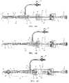
- FIG. 5is a plan view of a coaxial expanding tip sheath showing the spacer ribs in the undeployed state.
- FIG. 6is a cross-sectional view of the coaxial expanding tip sheath of FIG. 5 .
- FIG. 7is a plan view of the coaxial expanding tip sheath of FIG. 5 with the spacer ribs in the deployed state.
- FIG. 8is a plan view of the optical fiber with a male luer fiber connector.
- FIG. 9is a plan view of the coaxial expanding tip sheath of FIG. 5 assembled with the optical fiber of FIG. 8 .
- FIG. 10is a partial cross-sectional view of assembly shown in FIG. 9 .
- FIG. 11is a plan view of the coaxial expanding tip sheath assembly shown in FIG. 9 with the spacer ribs in the deployed state.
- FIG. 12Aillustrates the spacer ribs in the undeployed state within a blood vessel.
- FIG. 12Bis a cross sectional view taken along the line 12 B- 12 B of FIG. 12A .
- FIG. 13Aillustrates the spacer ribs in the deployed state within the blood vessel.
- FIG. 13Bis a cross sectional view taken along the line 13 B- 13 B of FIG. 13A .
- FIG. 14is a schematic of the distal end of an alternative embodiment of the endovascular laser treatment device within the vein.
- FIG. 15is a schematic of the FIG. 14 embodiment in the deployed position within the vein.
- FIG. 16is a schematic of the distal end of another embodiment of the endovascular laser treatment device in the undeployed position using a balloon mechanism.
- FIG. 17is a schematic of the FIG. 16 embodiment in the deployed position within the vein.
- the endovascular laser treatment device 1 shown in FIG. 1 and FIG. 2includes an optical fiber 3 which is comprised of clad-coated fiber 13 and jacket 15 .
- the devicealso includes an outer sleeve 17 , fitting assembly 7 , which also acts as a deployment mechanism, compression gasket 45 and a compression cap 47 .
- the optical fiber 3transmits the laser energy from a laser generator (not shown) into a vessel.
- the fitting assembly 7acts as a deployment mechanism for a spacer element to be discussed in detail later herein.
- the compression gasket 45 and compression cap 47provide a sealing function and when compressed, generate friction sufficient to maintain the position of the optical fiber 3 .
- the optical fiber 3is typically comprised of a 600-micron laser fiber 13 encased in a thick polymer jacket 15 for the entire length of the fiber 3 except for approximately 4 mm at the distal end.
- the jacket 15prevents the fragile fiber from breaking during use.
- a thin intermediate cladding(not shown) creates a barrier through which the laser energy cannot penetrate, thus causing the energy to move longitudinally through the fiber 3 to the distal end where the laser energy is emitted.
- the bare fiber 13extends unprotected from the polymer jacket 15 .
- the proximal end of the optical fiber 3is connected to a SMA or similar-type connector 9 , which can be attached to the laser generator (not shown).
- the optical fiber tipis ground and polished to form a flat face 11 .
- the flat face 11 of the optical fiber 3 tipdirects the laser energy from the fiber in a longitudinal direction.
- the outer sleeve 17is a tubular structure preferably comprised of a flexible, low-friction material such as nylon.
- the outer sleeve 17is arranged coaxially around the optical fiber 3 .
- the outer sleeve 17 inner diameteris preferably about 0.045′′, although other diameters can be used for different optical fiber sizes.
- the outer diameter of the sleeve 17is sized to fit within a standard 5F sheath.
- a sleeve 17 dimensioned with a 0.066′′ outer diametershould slidably fit within the lumen of a 5F sheath, which has an approximate inner diameter of 0.070′′.
- the outer sleeve 17is coaxially arranged around the optical fiber 3 and permanently attached to the fiber 3 at the distal end of the sleeve 17 at point 23 which defines a bonding zone between the fiber 3 and the distal end of the sleeve 17 .
- the outer sleeve 17can be moved longitudinally relative to the optical fiber 3 except at the point 23 .
- the sleeve 17includes a plurality of longitudinal slits 21 in the tubing at the distal end to define a plurality of ribs 19 each arranged between two adjacent slits. Preferably, there are three to six slits while the embodiment shown has five slits to define five ribs 19 .
- the ribs 19 disposed near the distal tip 11 of the optical fiber 3define a spacer element that positions the distal tip 11 away from the inner wall of the vessel.
- the slits 21expand radially outward to deploy the spacer element 19 , as will be explained in more detail below.
- the sleeve 17is permanently bonded to the distal fitting component 33 at the sleeve/fitting assembly bond point 25 , as more clearly shown in FIG. 2 .
- a fitting assembly 7 positioned at the proximal end of the outer sleeve 17provides the mechanism by which the spacer element 19 is moved from an undeployed to deployed position.
- the fitting assembly 7is comprised of a distal fitting component 33 , a proximal fitting component 35 and a compression cap 47 threadably connected to the proximal fitting component 35 .
- the two fitting components 33 and 35are permanently attached together at bond point 41 .
- the distal fitting component 33includes a male luer connector 27 or other similar type connection element which functions to connect the endovascular laser treatment device 1 to other commonly used medical devices such as a hemostasis sheath.
- the outer sleeve shaft 17is bonded to the male luer connector 27 of the distal fitting component 33 at point 25 .
- the distal fitting component 33has a longitudinal channel 39 through which the optical fiber 3 is positioned.
- the proximal fitting component 35also includes a longitudinal channel 39 , as shown in FIG. 2 , through which the optical fiber 3 is positioned.
- the proximal end of the fitting component 35includes a cavity into which a gasket 45 is positioned.
- the gasket 45is made of silicone or other compressible material with a central opening through which the optical fiber 3 passes.
- the gasket 45provides the dual functions of sealing the channel 39 and providing friction sufficient to maintain the longitudinal position of the optical fiber 3 within the channel 39 .
- the gasket compression threads 43 at the proximal end of fitting component 35provide an axially moveable connection between the fitting 35 and the compression cap 47 .
- the proximal fitting component 35 and the distal fitting component 33form a hollow positioning chamber 31 as shown in FIG. 2 .
- a positioning element 29that is permanently attached to the optical fiber jacket 15 at bond point 37 .
- the positioning element 29provides the function of limiting the longitudinal movement of the combined fitting assembly 7 /outer sleeve 17 relative to the optical fiber 3 .
- the positioning element 29In the undeployed position, the positioning element 29 is in contact with the distal chamber face 65 . Longitudinal movement of fitting assembly causes the positioning element 29 to be repositioned within the chamber 31 . Forward longitudinal movement of the fitting 7 /outer sleeve 17 is stopped when the positioning element 29 comes in contact with proximal chamber face 67 .
- the spacer element 19When the positioning element 29 is against the proximal chamber face 67 , the spacer element 19 is fully deployed as illustrated in FIG. 3 . In this position, the spacer ribs 19 are expanded radially outward, forming a space barrier between the fiber tip 11 and the inner vein wall.
- the mechanism for expansionis based on the forward longitudinal movement of the outer sleeve 17 proximal to the fiber/sleeve distal bond point 23 . Since the optical fiber 3 is held stationary during deployment, and the fiber is permanently bonded to the sleeve 17 at point 23 , the portion of the sleeve 17 within the slit zone expands as the sleeve is pushed forward.
- the device 1is designed to allow expansion of the slit zone to a maximum predetermined diameter. Alternatively, an intermediate expansion diameter can be achieved by controlling the amount of longitudinal movement within the chamber 31 .
- the spacer element 19provides several important advantages among others.
- the outer diameter and profile of the spacer element 19is equal to the outer sleeve 17 , allowing for easy insertion and positioning within the vein.
- the fitting assembly 7provides the user with an easy, simple means for deploying the spacer element 19 while maintaining the position of the fiber tip 11 stationary within the vein.
- the spacer element 19creates a barrier between the fiber tip 11 and the inner vein wall, thereby minimizing unequal laser energy distribution.
- FIGS. 1-3may be used with a standard hemostasis introducer sheath.
- Endovenous laser sheathsare typically 45 centimeters in length, although 60 and 65 centimeter sheaths are also well known in the art.
- the length of the endovascular laser treatment device 1is determined based on the length of the sheath being used for the procedure. According to the invention, the endovascular laser treatment device 1 can be sized to fit standard-length sheaths or custom-length sheaths. Further, the assembly 1 can be provided by itself or in a package that includes either the standard length sheath or custom-length sheath.
- FIGS. 4A-4Cshow the endovascular laser treatment device 1 with a hemostasis introducer sheath 49 .
- the hemostasis introducer sheath assembly 49is comprised of a sheath shaft 53 , a sheath distal tip 51 , a esidearm port 57 with connecting tubing, a stopcock assembly 61 , and a hemostasis valve gasket 59 housed within proximal opening of the sheath fitting 55 .
- a connector element 63provides a means to connect the hemostasis sheath assembly 49 to the endovascular laser treatment device 1 .
- the fiber tip 11 /outer sleeve 17 tipis first inserted into and advanced through the sheath connector element 63 and sheath shaft 53 lumen until the sheath tip 51 and fiber tip 11 are in substantial alignment as shown in FIG. 4A .
- the usermay adjust the position of the combined laser treatment device 1 and sheath 49 . Maintaining the fiber tip 11 position relative to the sheath tip 51 position during any user adjustments may be facilitated by the use of a temporary stop (not shown) slidably connected to the fiber 3 .
- the temporary stop mechanismwas previously disclosed in U.S. patent application Ser. No. 10/316,545, filed Dec. 11, 2002 and entitled “Endovascular Laser Treatment Device”, which is incorporated herein by reference. The temporary stop maintains the fiber tip 11 /sheath tip 51 alignment in a protective position until removed by the user.
- the sheath fitting 55is retracted while holding the fiber 3 stationary. Retracting the sheath fitting 55 rather than advancing the fiber 3 ensures that the correct pre-operative fiber tip 11 /spacer element 19 position is maintained.
- the sheath fitting 55is retracted until the sheath connector element 63 comes into contact with the male luer connector 27 . Threading the two connectors 27 and 63 together securely connects the endovascular laser treatment device 1 to the hemostasis introducer sheath assembly 49 . Once connected, the fiber tip 11 and spacer element 19 are automatically exposed in the proper operable position.
- a dual-thread arrangement, commonly used in medical devices,is shown in FIG. 4B , but other methods of connection may be used to connect the two fittings together.
- FIG. 4Bshows the endovascular laser treatment device 1 /hemostasis introducer sheath 49 connected with the spacer element 19 in the exposed and undeployed position.
- the distal segment of the outer sleeve shaft 17extends beyond the sheath tip 51 enough to completely expose the length of the slits 21 .
- the optical fiberis held stationary while the connected sheath fitting 55 /fitting assembly 7 is advanced forward. Longitudinal movement of connected fittings 55 and 7 cause the positioning element 29 to be repositioned within the chamber 31 . Forward longitudinal movement of the fitting 7 /outer sleeve 17 is stopped when the positioning element 29 comes in contact with proximal chamber face 67 .
- the spacer element 19When the positioning element 29 is against the proximal chamber face 67 , the spacer element 19 is fully deployed as illustrated in FIG. 4C . In this position, the spacer ribs 19 are expanded radially outward, forming a space barrier between the fiber tip 11 and the inner vein wall.
- the coaxial sleeve 71consists of an outer sleeve or tube 75 and inner sleeve or tube 77 permanently connected at the distal end by an outer/inner sleeve fuse section 79 .
- Standard welding/melting methodsmay be used to permanently fuse the two sleeves together at the fuse section 79 .
- the two sleevesare slideable relative to each other, except at the fuse section 79 .
- the fittingis comprised of a distal fitting component 81 and a proximal fitting component 83 .
- the two componentsare slidably connected with each other.
- the distal fitting component 81is in coaxial arrangement with the proximal fitting component 83 , allowing for longitudinal movement between the two components relative to each other.
- Gripping surface 101 of distal fitting component 81may be used to facilitate longitudinal movement between the two components.
- Both deployment fittings 81 and 83include a through lumen 99 , through which the optical fiber 3 (not shown) may be inserted.
- the outer sleeve 75 of the coaxial sleeve 71is securely attached to the distal fitting component 81 at connection point 95 .
- the inner sleeve 77 of coaxial sleeve 71is securely attached to the proximal fitting component 83 at connection point 97 .
- Proximal fitting component 83includes a standard female luer connector 93 that is connectable to the male luer fiber connector 103 shown in FIG. 8 and described in more detail below.
- the proximal fitting component 83includes a longitudinally positioned multiple detent slot 87 , as shown in FIG. 5 and FIG. 7 .
- a pin 85 attached to the distal fitting component 81slides longitudinally within the detent slot 87 of the proximal fitting component 83 .
- FIG. 5shows the coaxial expanding tip sheath 69 with the deployment fitting assembly 73 in the undeployed position, as indicated by the position of pin 85 .
- pin 85is in the proximal detent position 91 , the sheath 69 is in an undeployed configuration.
- the intermediate detent positions in slot 87may be used to control the extent of expansion of the spacer element 19 .
- This featureallows varying diameter veins to be treated with the same device. For example, positioning the pin 85 as described above to the detent position just distal of detent position 91 will expand the rib elements 19 only slightly. Positioning the pin 85 in more distal detent positions will cause further expansion of the rib elements 19 .
- the ribs 19are at the maximum expanded state when the pin is in detent position 89 .
- FIG. 8depicts an optical fiber assembly modified for use with the coaxial expanding tip sheath embodiment of FIG. 5 to FIG. 7 .
- This optical fiber embodimentwas previously disclosed in U.S. patent application Ser. No. 10/316,545, filed Dec. 11, 2002 entitled “Endovascular Laser Treatment Device” and is hereby incorporated by reference.
- the optical fiber assembly of FIG. 8comprises an optical fiber 13 , 15 , a standard SMA connector 9 for connection to a laser generator (not shown), and a male luer fiber connector 103 bonded to the optical fiber 3 at connector/fiber bond point 105 .
- Approximately 2-4 mm of the optical fiber 3 distal endis bare fiber 13 with cladding.
- Fiber optic tipis identified as 11 .
- the male luer connector 103includes a through-hole through which the fiber 3 passes and through which the fiber 3 is bonded to the connector 103 at bond point 105 .
- FIGS. 9 and 10illustrate the coaxial expanding tip sheath embodiment coupled to an optical fiber of FIG. 8 in an undeployed configuration.
- the fiber 3can be inserted and positioned as shown in FIG. 9 prior to insertion of the device or after the coaxial expanding tip sheath 69 has been placed within the vein.
- the distal tip 11 of the fiberis inserted and advanced through common lumen 99 ( FIG. 6 ) of the proximal fitting component 83 , distal fitting component 81 lumen 99 and inner sleeve lumen, and the two luer connectors are locked with each other to securely attach the fiber 3 to the sheath 69 .
- the outer tube 75is positioned within the blood vessel 115 as shown in FIGS. 12A and 12B .
- the spacer ribs 19are in the deployed state within the vessel 115 , the expanded spacer ribs 19 position the fiber tip 11 away from the inner wall of the vessel as shown in FIGS. 13A and 13B .
- the spacer ribs 19do not have to be centered within the vessel lumen. The spacer ribs 19 can be deployed such that only some of the ribs contact the inner vessel wall and still provide sufficient space to prevent the fiber tip 11 from directly contacting the vessel wall.
- the expanding tip sheath 69 embodimentis advantageous in several respects.
- the single devicefunctions as both an introducer sheath and a spacer device for the fiber tip.
- the size of the overall deviceis smaller in diameter than if separate components were used in the procedure. Accordingly, the size of the access puncture is smaller and less traumatic to the patient.
- the expanding tip sheath 69is independent of the optical fiber 3 allowing separate placement and withdrawal of the fiber, if desired.
- This embodimentalso allows the introduction of diagnostic and interventional devices and fluids through the sheath lumen 99 .
- the sheath 69can be optionally inserted directly over a standard guidewire as part of the placement and positioning step. Saline or other procedural fluids can be introduced through the sheath lumen 99 into the vein.
- the fitting assembly 73provides the user with an easy, simple means for deploying the spacer element 19 while maintaining the position of the fiber tip 11 stationary within the vein. When deployed, the spacer element 19 creates a barrier between the fiber tip 11 and the inner vein wall whereby minimizing unequal laser energy distribution.
- FIG. 14is a schematic of an expanding spacer 109 within a retractable sleeve 107 which has been placed into a vein 115 .
- the expanding spacer 109is comprised of a plurality of spacer ribs 111 , or more particularly spacer legs, which are attached to the outer wall of the optical fiber 3 by a circumferential ring 113 .
- Standard bonding or welding techniques well known in the artcan be used to affix the circumferential ring 113 to the optical fiber 3 and spacer legs 111 .
- the spacer legs 111 and the circumferential ring 113can be fabricated as a single unit and then attached to the optical fiber 3 .
- the spacer legs 111are pre-curved and preferably made of nitinol or other shape memory type material such as stainless steel or a polymer material.
- the expanding spacer 109is formed of three to six legs 111 although other configurations are possible.
- the retractable sleeve 107retains the plurality of legs 111 within their unexpanded and undeployed position around the optical fiber 3 .
- the fiber tip 11extends beyond the spacer legs 111 by 1-3 cm.
- the retractable sleeve 107is withdrawn while holding the fiber 3 stationary. Any of the previously described deployment configurations can be used to perform the retraction function. Withdrawing the retractable sleeve 107 exposes the spacer legs 111 . Due to the shape-memory characteristics of the spacer legs 111 , withdrawal of the sleeve 107 causes the spacer legs 111 to expand radially outward to contact the inner vessel wall 115 , as shown in FIG. 15 . The expanded spacer legs 111 form a cage over the distal end of the device, ensuring that the exposed fiber tip 11 and bare fiber section 13 remain out of contact with the inner wall of the vessel lumen.
- the spacer legs 111can be deployed such that only some of the legs contact the inner vessel wall and still provide sufficient space to prevent the fiber tip 11 from directly contacting the vessel wall.
- the amount of radial expansion of the spacer legs 109can be controlled to accommodate various sizes of the vessels.
- FIG. 16depicts the balloon 117 assembly in a deflated state within the vein segment 115 .
- the balloon 117is attached to the fiber 3 at distal bond point 123 and to the outer shaft 119 at proximal bond point 125 .
- the shaft or tube 119forms a coaxial lumen providing for a balloon inflation/deflation lumen 121 .
- the shaft 119may be a multi-lumen tube with distinct lumens for the fiber 3 and for the balloon inflation/deflation lumen.
- the balloonmay be formed from nylon, latex or other similar material well-known in the prior art.
- the shaft 119 and fiber 3are inserted and advanced to the treatment location with the balloon 117 in a deflated position as shown in FIG. 16 .
- the balloon 117Prior to activating the laser generator, the balloon 117 is deployed by injecting saline or other fluid through the inflation/deflation lumen 121 into the balloon 117 . As fluid fills the balloon 117 , it expands to prevent the fiber tip 11 from contacting the inner vessel wall 115 as shown in FIG. 17 .
- the deployed balloonmaintains the position of the fiber tip 11 within the vein lumen and away from the vessel wall.
- the balloonis switched to its undeployed deflated state by withdrawing fluid from the balloon through the inflation/deflation lumen 121 using suction or other standard deflation techniques.
- the treatment procedurebegins with the standard pre-operative preparation of the patient as is well known in the laser treatment art.
- the patient's diseased venous segmentsare marked on the skin surface.
- ultrasound guidanceis used to map the greater saphenous vein from the sapheno-femoral junction to the popliteal area.
- the greater saphenous veinis accessed using a standard Seldinger technique.
- a small gauge needleis used to puncture the skin and access the vein.
- a guide wireis advanced into the vein through the lumen of the needle. The needle is then removed leaving the guidewire in place.
- a hemostasis introducer sheath 49(as depicted in FIG. 4A ) may be introduced into the vein over the guidewire and advanced to 1 to 2 centimeters below the sapheno-femoral junction.
- the sheath 49includes a valve gasket 59 that provides a leak-proof seal to prevent the backflow of blood out the sheath proximal opening while simultaneously allowing the introduction of fibers, guidewires and other interventional devices into the sheath.
- the valve gasket 59is made of elastomeric material such as a rubber or latex, as commonly found in the art.
- the gasket 59opens to allow insertion of the optical fiber 3 and then seals around the outer sleeve shaft 17 .
- the valve gasket 59does not open in response to pressure from the distal side in order to prevent the back-flow of blood or other fluids.
- the gasket 59also prevents air from entering the sheath through the proximal hub opening.
- An inner dilatormay be coupled with the hemostasis sheath to facilitate insertion and advancement of the sheath through the vein. Position of the sheath is then verified and adjusted if necessary using ultrasound. Once correct positioning is confirmed, the guide wire and dilator, if used, are removed leaving the sheath in place.
- Procedural fluidsmay be flushed through the sheath lumen through the side arm stopcock assembly 61 coupled to the sheath through a sidearm port 57 .
- One commonly administered fluid during an endovascular laser treatment procedureis saline which is used to flush blood from the hemostasis sheath 49 prior to or after insertion of the optical fiber 3 /fitting assembly 7 . Blood is often flushed from the sheath 49 to prevent the adherence of blood to the flat face tip 11 of the optical fiber 3 , which can adversely affect the intensity and direction of the laser energy within the vessel.
- the sidearm stopcock assembly 61can also be used to administer emergency drugs directly into the vein.
- the distal end of the endovascular laser treatment device 1is inserted into and is advanced through the sheath 49 until positioned as shown in FIG. 4A .
- a temporary stop(not shown) slidably connected around the sleeve 17 which is positioned between the male luer connector 27 of the fitting assembly 7 and the sheath connector 63 ensures that the fiber tip 11 position relative to the sheath tip 51 is maintained during any user adjustments.
- the temporary stopis preferred because it ensures that the fiber tip 11 is in coaxial alignment with the sheath tip 51 .
- the tissue immediately surrounding the diseased vessel segmentis subjected to numerous percutaneous injections of a tumescent anesthetic agent.
- the injectionstypically lidocaine with or without epinephrine, are administered along the entire length of the greater saphenous vein using ultrasonic guidance and the markings previously mapped out on the skin surface.
- the tumescent injectionsperform several functions. The anesthesia inhibits pain caused from the application of laser energy to the vein.
- the tumescent injectionalso provides a barrier between the vessel and the adjacent tissue and nerve structures, which restricts the heat damage to within the vessel and prevents non-target tissue damage.
- the device 1is placed in the deployed position in preparation for the delivery of laser energy to the vein lumen. Specifically, the temporary stop is removed and the sheath is withdrawn until the sheath connector 63 comes into contact with the male luer connector 27 of the fitting assembly 7 . The two connectors 63 and 27 are threaded together to attach the sheath 49 to the fitting assembly 7 . The retraction of the sheath 49 exposes the fiber tip 11 and the slit zone 21 as shown in FIG. 4B . To deploy the spacer ribs 19 that are in their undeployed state as shown in FIG.
- the userholds the fiber 3 stationary while advancing the combined fitting assembly 7 /sheath 49 as a unit.
- This actioncauses the outer sleeve shaft 17 to advance distally and the ribs 19 to expand radially outward against the vessel wall into their deployed state as shown in FIG. 4C .
- the positioning element 29prevents over-expansion of the ribs by contact with the proximal chamber face 67 .
- the device 1is now in the operating position, ready to delivery laser energy to the diseased vein.
- a laser generator(not shown) is connected to the SMA connector 9 of fiber 3 and is activated.
- the combined sheath 49 /endovascular laser treatment device 1is then slowly withdrawn as a single unit through the vein, preferably at a rate of 1-3 millimeters per second.
- the laser energytravels down the optical fiber 3 , through the tip 11 of the optical fiber 3 and into the vein lumen, where it creates hot bubbles of gas in the bloodstream.
- the gas bubblesexpand to contact the vein wall, along a 360-degree circumference, thus damaging vein wall tissue, and ultimately causing collapse of the vessel.
- the laser energyshould be directed forward in the bloodstream to create the bubbles of gas.
- the deployed ribsensure that the laser energy is directed forward into the bloodstream rather than being mis-directly radially against the vessel wall. Misdirected delivery of laser energy may result in vessel wall perforations where heat is concentrated and incomplete tissue necrosis where insufficient thermal energy is delivered.
- the endovascular treatment device 1 of the present invention with a fiber tip spacer 19avoids these problems by preventing contact between the fiber tip 13 and the vessel's inner wall as the device is withdrawn through the vessel.
- the procedure for treating the varicose veinis considered to be complete when the desired length of the greater saphenous vein has been exposed to laser energy. Normally, the laser generator is turned off when the fiber tip 11 is approximately 3 centimeters from the access site. The combined sheath 49 /endovascular laser treatment device 1 is then removed from the body as a single unit.
- the spacer elementcan be of various designs as long as it positions the fiber tip away from the vessel wall when the laser generator is activated.
- a non-expanding, thin, ceramic-type sleeve bonded to the fiber jacketmay be used for the spacer mechanism.
- the ceramic sleeveextends over and is spaced radially away from the fiber tip to prevent vessel wall contact. Although thin, the ceramic sleeve would provide the necessary barrier between the vessel wall and fiber tip to prevent unequal laser energy delivery.
- the method of providing attachment of the fiber assembly connector and the hemostasis valve housingcan be accomplished in many ways.
- the described embodimentdepicts a dual thread arrangement, but methods such as snap fits or any other means for providing a secure but releasable connection could be used.
- the diameter size of the optical fibercan also be modified. Although 600-micron diameter optical fibers are most commonly used in endovenous laser treatment of varicose veins, diameters as small as 200 microns, for example, can be used. With a smaller diameter optical fiber, the outer sleeve provides not only the functions previously identified above, but also an increase in overall durability of the device. Specifically, the coaxially mounted sleeve provides added protection and strength to the optical fiber.
Landscapes
- Health & Medical Sciences (AREA)
- Surgery (AREA)
- Physics & Mathematics (AREA)
- Life Sciences & Earth Sciences (AREA)
- Engineering & Computer Science (AREA)
- Medical Informatics (AREA)
- Nuclear Medicine, Radiotherapy & Molecular Imaging (AREA)
- Electromagnetism (AREA)
- Optics & Photonics (AREA)
- Biomedical Technology (AREA)
- Heart & Thoracic Surgery (AREA)
- Otolaryngology (AREA)
- Molecular Biology (AREA)
- Animal Behavior & Ethology (AREA)
- General Health & Medical Sciences (AREA)
- Public Health (AREA)
- Veterinary Medicine (AREA)
- Laser Surgery Devices (AREA)
Abstract
Description
Claims (5)
Priority Applications (10)
| Application Number | Priority Date | Filing Date | Title |
|---|---|---|---|
| US10/613,395US7273478B2 (en) | 2002-07-10 | 2003-07-03 | Endovascular treatment device having a fiber tip spacer |
| US11/777,198US7559329B2 (en) | 2002-07-10 | 2007-07-12 | Method of treating a blood vessel with an optical fiber having a spacer |
| EP08745403.9AEP2134282B1 (en) | 2002-07-10 | 2008-04-09 | Device for endovascular treatment for causing closure of a blood vessel |
| US12/100,309US8864754B2 (en) | 2002-07-10 | 2008-04-09 | Device and method for endovascular treatment for causing closure of a blood vessel |
| PCT/US2008/059791WO2008124790A2 (en) | 2002-07-10 | 2008-04-09 | Device and method for endovascular treatment for causing closure of a blood vessel |
| US12/109,835US20080208180A1 (en) | 2002-07-10 | 2008-04-25 | Endovascular treatment sheath having a heat insulative tip and method for using the same |
| US12/164,674US20080287939A1 (en) | 2002-07-10 | 2008-06-30 | Endovascular thermal treatment device with flexible guide tip and method |
| US12/496,515US8425501B2 (en) | 2002-07-10 | 2009-07-01 | Method of treating a blood vessel with an optical fiber having a spacer |
| US13/850,932US8840606B2 (en) | 2002-07-10 | 2013-03-26 | Method of treating a blood vessel with an optical fiber having a spacer |
| US14/465,490US20140358134A1 (en) | 2002-07-10 | 2014-08-21 | Method of Treating a Blood Vessel with an Optical Fiber Having a Spacer |
Applications Claiming Priority (2)
| Application Number | Priority Date | Filing Date | Title |
|---|---|---|---|
| US39521802P | 2002-07-10 | 2002-07-10 | |
| US10/613,395US7273478B2 (en) | 2002-07-10 | 2003-07-03 | Endovascular treatment device having a fiber tip spacer |
Related Parent Applications (1)
| Application Number | Title | Priority Date | Filing Date |
|---|---|---|---|
| US10/836,084Continuation-In-PartUS7458967B2 (en) | 2002-07-10 | 2004-04-30 | Endovascular treatment apparatus and method |
Related Child Applications (1)
| Application Number | Title | Priority Date | Filing Date |
|---|---|---|---|
| US11/777,198ContinuationUS7559329B2 (en) | 2002-07-10 | 2007-07-12 | Method of treating a blood vessel with an optical fiber having a spacer |
Publications (2)
| Publication Number | Publication Date |
|---|---|
| US20040010248A1 US20040010248A1 (en) | 2004-01-15 |
| US7273478B2true US7273478B2 (en) | 2007-09-25 |
Family
ID=30115837
Family Applications (5)
| Application Number | Title | Priority Date | Filing Date |
|---|---|---|---|
| US10/613,395Expired - LifetimeUS7273478B2 (en) | 2002-07-10 | 2003-07-03 | Endovascular treatment device having a fiber tip spacer |
| US11/777,198Expired - LifetimeUS7559329B2 (en) | 2002-07-10 | 2007-07-12 | Method of treating a blood vessel with an optical fiber having a spacer |
| US12/496,515Expired - Fee RelatedUS8425501B2 (en) | 2002-07-10 | 2009-07-01 | Method of treating a blood vessel with an optical fiber having a spacer |
| US13/850,932Expired - LifetimeUS8840606B2 (en) | 2002-07-10 | 2013-03-26 | Method of treating a blood vessel with an optical fiber having a spacer |
| US14/465,490AbandonedUS20140358134A1 (en) | 2002-07-10 | 2014-08-21 | Method of Treating a Blood Vessel with an Optical Fiber Having a Spacer |
Family Applications After (4)
| Application Number | Title | Priority Date | Filing Date |
|---|---|---|---|
| US11/777,198Expired - LifetimeUS7559329B2 (en) | 2002-07-10 | 2007-07-12 | Method of treating a blood vessel with an optical fiber having a spacer |
| US12/496,515Expired - Fee RelatedUS8425501B2 (en) | 2002-07-10 | 2009-07-01 | Method of treating a blood vessel with an optical fiber having a spacer |
| US13/850,932Expired - LifetimeUS8840606B2 (en) | 2002-07-10 | 2013-03-26 | Method of treating a blood vessel with an optical fiber having a spacer |
| US14/465,490AbandonedUS20140358134A1 (en) | 2002-07-10 | 2014-08-21 | Method of Treating a Blood Vessel with an Optical Fiber Having a Spacer |
Country Status (5)
| Country | Link |
|---|---|
| US (5) | US7273478B2 (en) |
| EP (1) | EP1539012B1 (en) |
| AU (1) | AU2003261120A1 (en) |
| ES (1) | ES2527051T3 (en) |
| WO (1) | WO2004004546A2 (en) |
Cited By (54)
| Publication number | Priority date | Publication date | Assignee | Title |
|---|---|---|---|---|
| US20050131400A1 (en)* | 2002-10-31 | 2005-06-16 | Cooltouch, Inc. | Endovenous closure of varicose veins with mid infrared laser |
| US20050288655A1 (en)* | 2004-06-29 | 2005-12-29 | Howard Root | Laser fiber for endovenous therapy having a shielded distal tip |
| US20060142747A1 (en)* | 2002-12-11 | 2006-06-29 | Appling William M | Method of thermally treating blood vessels |
| US20070073278A1 (en)* | 2005-09-16 | 2007-03-29 | Johnson Kevin C | Cardiac Ablation Dosing |
| US20070123846A1 (en)* | 2002-10-31 | 2007-05-31 | Cooltouch Incorporated | Preparation for endovenous laser ablation |
| US20070179486A1 (en)* | 2004-06-29 | 2007-08-02 | Jeff Welch | Laser fiber for endovenous therapy having a shielded distal tip |
| US20070299431A1 (en)* | 2006-05-02 | 2007-12-27 | Green Medical, Inc. | Systems and methods for treating superficial venous malformations like spider veins |
| US20080015559A1 (en)* | 2002-07-10 | 2008-01-17 | Appling William M | Endovascular treatment device having a fiber tip spacer |
| US20080071333A1 (en)* | 2002-10-31 | 2008-03-20 | Cooltouch Incorporated | Restless leg syndrome treatment |
| US20080188843A1 (en)* | 2002-07-10 | 2008-08-07 | Appling William M | Device and method for endovascular treatment for causing closure of a blood vessel |
| US20080208180A1 (en)* | 2002-07-10 | 2008-08-28 | Cartier William A | Endovascular treatment sheath having a heat insulative tip and method for using the same |
| US20080300583A1 (en)* | 2007-06-01 | 2008-12-04 | Ceramoptec Industries, Inc. | Vascular laser treatment device and method |
| US20080300662A1 (en)* | 2007-06-01 | 2008-12-04 | Spectranetics | Custom Laser Sequences |
| US20090082760A1 (en)* | 2007-09-25 | 2009-03-26 | Kenneth Zinn | Guidewire tipped laser fiber |
| US20100168823A1 (en)* | 2004-02-09 | 2010-07-01 | John Strisower | Method and apparatus for the treatment of respiratory and other infections using ultraviolet germicidal irradiation |
| US20100234925A1 (en)* | 2009-03-16 | 2010-09-16 | PinPoint U.S.A., Inc. | Treatment of microbiological pathogens in a toe nail with antimicrobial light |
| US20110172586A1 (en)* | 2009-07-22 | 2011-07-14 | Cooltouch Incorporated | Treatment of Microbial Infections Using Hot and Cold Thermal Shock and Pressure |
| US8291915B2 (en) | 1997-03-04 | 2012-10-23 | Tyco Healthcare Group Lp | Method and apparatus for treating venous insufficiency using directionally applied energy |
| US8435235B2 (en) | 2007-04-27 | 2013-05-07 | Covidien Lp | Systems and methods for treating hollow anatomical structures |
| US8535360B2 (en) | 2006-05-02 | 2013-09-17 | Green Medical, Ltd. | Systems and methods for treating superficial venous malformations like spider veins |
| US8961551B2 (en) | 2006-12-22 | 2015-02-24 | The Spectranetics Corporation | Retractable separating systems and methods |
| US9028520B2 (en) | 2006-12-22 | 2015-05-12 | The Spectranetics Corporation | Tissue separating systems and methods |
| US9283040B2 (en) | 2013-03-13 | 2016-03-15 | The Spectranetics Corporation | Device and method of ablative cutting with helical tip |
| US9291663B2 (en) | 2013-03-13 | 2016-03-22 | The Spectranetics Corporation | Alarm for lead insulation abnormality |
| CN105662579A (en)* | 2016-03-08 | 2016-06-15 | 四川航天世都制导有限公司 | Novel laser treatment handle |
| US9413896B2 (en) | 2012-09-14 | 2016-08-09 | The Spectranetics Corporation | Tissue slitting methods and systems |
| USD765243S1 (en) | 2015-02-20 | 2016-08-30 | The Spectranetics Corporation | Medical device handle |
| US9456872B2 (en) | 2013-03-13 | 2016-10-04 | The Spectranetics Corporation | Laser ablation catheter |
| USD770616S1 (en) | 2015-02-20 | 2016-11-01 | The Spectranetics Corporation | Medical device handle |
| US9603618B2 (en) | 2013-03-15 | 2017-03-28 | The Spectranetics Corporation | Medical device for removing an implanted object |
| US9618700B1 (en) | 2015-12-03 | 2017-04-11 | InnovaQuartz LLC | Orthogonal output optical fiber |
| US9662173B1 (en) | 2015-12-24 | 2017-05-30 | Cyclone Biosciences LLC | Lateral delivery device with active cooling |
| US9668765B2 (en) | 2013-03-15 | 2017-06-06 | The Spectranetics Corporation | Retractable blade for lead removal device |
| US9770297B2 (en) | 2008-06-04 | 2017-09-26 | Covidien Lp | Energy devices and methods for treating hollow anatomical structures |
| US9814513B2 (en) | 2011-06-30 | 2017-11-14 | Angiodynamics, Inc. | Endovascular plasma treatment device and method of use |
| US9883885B2 (en) | 2013-03-13 | 2018-02-06 | The Spectranetics Corporation | System and method of ablative cutting and pulsed vacuum aspiration |
| US9925366B2 (en) | 2013-03-15 | 2018-03-27 | The Spectranetics Corporation | Surgical instrument for removing an implanted object |
| US9980743B2 (en) | 2013-03-15 | 2018-05-29 | The Spectranetics Corporation | Medical device for removing an implanted object using laser cut hypotubes |
| US10092356B2 (en) | 2015-11-18 | 2018-10-09 | InnovaQuartz LLC | Radial emissions from optical fibers |
| US10136913B2 (en) | 2013-03-15 | 2018-11-27 | The Spectranetics Corporation | Multiple configuration surgical cutting device |
| US10383691B2 (en) | 2013-03-13 | 2019-08-20 | The Spectranetics Corporation | Last catheter with helical internal lumen |
| US10405924B2 (en) | 2014-05-30 | 2019-09-10 | The Spectranetics Corporation | System and method of ablative cutting and vacuum aspiration through primary orifice and auxiliary side port |
| US10448999B2 (en) | 2013-03-15 | 2019-10-22 | The Spectranetics Corporation | Surgical instrument for removing an implanted object |
| US10835279B2 (en) | 2013-03-14 | 2020-11-17 | Spectranetics Llc | Distal end supported tissue slitting apparatus |
| US10842532B2 (en) | 2013-03-15 | 2020-11-24 | Spectranetics Llc | Medical device for removing an implanted object |
| US10980523B1 (en)* | 2019-11-01 | 2021-04-20 | Stephanie Toy | Medical device to access pericardial space with control |
| US11253318B2 (en) | 2018-08-21 | 2022-02-22 | Optical Integrity, Inc. | Arrangement for filtering out damaging heat created from laser energy contacting a kidney stone |
| US11372182B2 (en)* | 2018-08-31 | 2022-06-28 | Synergia Medical | Optical fibres connector for optoelectronic active implantable medical device (AIMD) |
| US11576724B2 (en) | 2011-02-24 | 2023-02-14 | Eximo Medical Ltd. | Hybrid catheter for vascular intervention |
| US11684420B2 (en) | 2016-05-05 | 2023-06-27 | Eximo Medical Ltd. | Apparatus and methods for resecting and/or ablating an undesired tissue |
| US11826097B2 (en) | 2015-11-18 | 2023-11-28 | Cyclone Biosciences, Llc | Forming radial emissions from optical fibers |
| US12038322B2 (en) | 2022-06-21 | 2024-07-16 | Eximo Medical Ltd. | Devices and methods for testing ablation systems |
| US12053203B2 (en) | 2014-03-03 | 2024-08-06 | Spectranetics, Llc | Multiple configuration surgical cutting device |
| US12376904B1 (en) | 2020-09-08 | 2025-08-05 | Angiodynamics, Inc. | Dynamic laser stabilization and calibration system |
Families Citing this family (23)
| Publication number | Priority date | Publication date | Assignee | Title |
|---|---|---|---|---|
| EP1581130A2 (en)* | 2002-10-31 | 2005-10-05 | CoolTouch, Incorporated | Endovenous closure of varicose veins with mid infrared laser |
| US20080021527A1 (en)* | 2003-10-30 | 2008-01-24 | Cooltouch Incorporated | Endovenous laser treatment generating reduced blood coagulation |
| US8409183B2 (en) | 2003-10-30 | 2013-04-02 | Cooltouch Incorporated | Endovenous laser treatment generating reduced blood coagulation |
| WO2006031541A1 (en)* | 2004-09-09 | 2006-03-23 | Vnus Medical Technologies, Inc. | Methods and apparatus for treatment of hollow anatomical structures |
| DE102005017204B4 (en)* | 2005-04-14 | 2012-03-22 | Lisa Laser Products Ohg Fuhrberg & Teichmann | Endoscope and method for introducing an optical fiber into a working channel of an endoscope |
| SE0501077L (en)* | 2005-05-12 | 2006-11-13 | Spectracure Ab | Device for photodynamic diagnosis or treatment |
| US7500974B2 (en)* | 2005-06-28 | 2009-03-10 | Covidien Ag | Electrode with rotatably deployable sheath |
| US20090171332A1 (en)* | 2007-12-27 | 2009-07-02 | Intuitive Surgical, Inc. | Medical device with orientable tip for robotically directed laser cutting and biomaterial application |
| US10085802B2 (en)* | 2008-02-28 | 2018-10-02 | Biolitec Unternehmensbeteiligungs Ii Ag | Endoluminal laser ablation device and method for treating veins |
| WO2010054456A1 (en)* | 2008-11-14 | 2010-05-20 | Wagner Paula Ferreira | Catheter for endoluminal laser with centralizer and apical sensors of temperature |
| NL2002597C2 (en) | 2009-03-06 | 2010-09-07 | Tobrix B V | Endovascular treatment device, system for endovascular treatment and method of operating |
| US10434292B2 (en)* | 2011-06-24 | 2019-10-08 | Access Closure | Method and devices for flow occlusion during device exchanges |
| WO2013119662A1 (en)* | 2012-02-06 | 2013-08-15 | Cornell University | Catheter based system and method for thrombus removal using time reversal acoustics |
| EP2823783A4 (en)* | 2012-03-06 | 2015-11-18 | Intermedic Arfran S A | Bidirectional self-centering tip for fiber optics designed for endovascular treatments |
| WO2015003159A1 (en) | 2013-07-03 | 2015-01-08 | UVL Blood Labs, Inc. | Vascular access device with integrated light guide |
| WO2015059316A1 (en) | 2013-10-21 | 2015-04-30 | Boné Salat Carlos | Device for treating truncal and/or collateral varicose veins, and synergistic physicochemical method of use |
| US20160030023A1 (en)* | 2014-07-31 | 2016-02-04 | Terumo Kabushiki Kaisha | Method for treating varicose veins and intraluminal device used in such method |
| KR101510133B1 (en)* | 2014-11-18 | 2015-04-09 | (주)휴레이저 | Handpiece treatment apparatus capable of adjusting length of optical fiber |
| US11191976B2 (en)* | 2017-05-19 | 2021-12-07 | Prometheus Therapeutics Inc. | Devices and methods for repair of a selected blood vessel or part thereof and rapid healing of injured internal body cavity walls |
| JP2019014679A (en) | 2017-07-07 | 2019-01-31 | ロレアル | Silicone-free composition for keratin fiber in form of ultra-fine o/w emulsion |
| WO2020019305A1 (en)* | 2018-07-27 | 2020-01-30 | 尚华 | Photodynamic therapy and diagnosis device capable of optical fiber puncturing |
| CN114727842A (en)* | 2019-09-30 | 2022-07-08 | 北极星医疗公司 | Sheath or catheter with dilator for transseptal puncture visualization and perforation and method of use thereof |
| CN113499088B (en)* | 2021-06-08 | 2022-05-06 | 郭宏波 | An intraluminal closure system for visualization of lower extremity varicose veins |
Citations (14)
| Publication number | Priority date | Publication date | Assignee | Title |
|---|---|---|---|---|
| US4817601A (en)* | 1985-03-06 | 1989-04-04 | C. R. Bard, Inc. | Catheter system for controlled removal by radiant energy of biological obstructions |
| EP0311295A2 (en) | 1987-10-07 | 1989-04-12 | University College London | Improvements in surgical apparatus |
| US5026366A (en)* | 1984-03-01 | 1991-06-25 | Cardiovascular Laser Systems, Inc. | Angioplasty catheter and method of use thereof |
| US5188635A (en)* | 1988-02-08 | 1993-02-23 | Wolfgang Radtke | Catheter for percutaneous surgery of blood vessels and organs using radiant energy |
| US5445608A (en)* | 1993-08-16 | 1995-08-29 | James C. Chen | Method and apparatus for providing light-activated therapy |
| US5643253A (en)* | 1995-06-06 | 1997-07-01 | Rare Earth Medical, Inc. | Phototherapy apparatus with integral stopper device |
| US5693043A (en)* | 1985-03-22 | 1997-12-02 | Massachusetts Institute Of Technology | Catheter for laser angiosurgery |
| US5725521A (en)* | 1996-03-29 | 1998-03-10 | Eclipse Surgical Technologies, Inc. | Depth stop apparatus and method for laser-assisted transmyocardial revascularization and other surgical applications |
| US6033398A (en)* | 1996-03-05 | 2000-03-07 | Vnus Medical Technologies, Inc. | Method and apparatus for treating venous insufficiency using directionally applied energy |
| US6344048B1 (en)* | 1997-07-10 | 2002-02-05 | Scimed Life Systems, Inc. | Removable occlusion system for aneurysm neck |
| US6398777B1 (en) | 1999-02-01 | 2002-06-04 | Luis Navarro | Endovascular laser device and treatment of varicose veins |
| US6561998B1 (en)* | 1998-04-07 | 2003-05-13 | Transvascular, Inc. | Transluminal devices, systems and methods for enlarging interstitial penetration tracts |
| US6767338B2 (en)* | 2000-10-24 | 2004-07-27 | Scimed Life Systems, Inc. | Variable tip catheter |
| US6986766B2 (en)* | 2001-06-15 | 2006-01-17 | Diomed Inc. | Method of endovenous laser treatment |
Family Cites Families (32)
| Publication number | Priority date | Publication date | Assignee | Title |
|---|---|---|---|---|
| US4564011A (en) | 1982-03-22 | 1986-01-14 | Leon Goldman | Laser optic device and method |
| US4773413A (en) | 1983-06-13 | 1988-09-27 | Trimedyne Laser Systems, Inc. | Localized heat applying medical device |
| DE3718139C1 (en)* | 1987-05-29 | 1988-12-08 | Strahlen Umweltforsch Gmbh | Cardiac catheter |
| US5030201A (en) | 1989-11-24 | 1991-07-09 | Aubrey Palestrant | Expandable atherectomy catheter device |
| US5897551A (en)* | 1990-03-23 | 1999-04-27 | Myriadlase, Inc. | Medical device for applying high energy light and heat for gynecological sterilization procedures |
| US5154708A (en)* | 1990-05-15 | 1992-10-13 | Surgical Laser Technologies, Inc. | Unitary scalpel for contact laser surgery |
| US5484384A (en)* | 1991-01-29 | 1996-01-16 | Med Institute, Inc. | Minimally invasive medical device for providing a radiation treatment |
| US5156151A (en)* | 1991-02-15 | 1992-10-20 | Cardiac Pathways Corporation | Endocardial mapping and ablation system and catheter probe |
| WO1992014515A1 (en)* | 1991-02-19 | 1992-09-03 | Advanced Interventional Systems, Inc. | Delivery system for pulsed excimer laser light |
| US5151096A (en) | 1991-03-28 | 1992-09-29 | Angiolaz, Incorporated | Laser catheter diffuser |
| US5239999A (en)* | 1992-03-27 | 1993-08-31 | Cardiac Pathways Corporation | Helical endocardial catheter probe |
| US5324284A (en)* | 1992-06-05 | 1994-06-28 | Cardiac Pathways, Inc. | Endocardial mapping and ablation system utilizing a separately controlled ablation catheter and method |
| US5807306A (en)* | 1992-11-09 | 1998-09-15 | Cortrak Medical, Inc. | Polymer matrix drug delivery apparatus |
| US5476495A (en)* | 1993-03-16 | 1995-12-19 | Ep Technologies, Inc. | Cardiac mapping and ablation systems |
| US5403311A (en)* | 1993-03-29 | 1995-04-04 | Boston Scientific Corporation | Electro-coagulation and ablation and other electrotherapeutic treatments of body tissue |
| US5431168A (en)* | 1993-08-23 | 1995-07-11 | Cordis-Webster, Inc. | Steerable open-lumen catheter |
| US5582609A (en)* | 1993-10-14 | 1996-12-10 | Ep Technologies, Inc. | Systems and methods for forming large lesions in body tissue using curvilinear electrode elements |
| US5507743A (en)* | 1993-11-08 | 1996-04-16 | Zomed International | Coiled RF electrode treatment apparatus |
| US5437664A (en)* | 1994-01-18 | 1995-08-01 | Endovascular, Inc. | Apparatus and method for venous ligation |
| US5573531A (en)* | 1994-06-20 | 1996-11-12 | Gregory; Kenton W. | Fluid core laser angioscope |
| US5617854A (en)* | 1994-06-22 | 1997-04-08 | Munsif; Anand | Shaped catheter device and method |
| DE4425195C1 (en)* | 1994-07-16 | 1995-11-16 | Osypka Peter | Heart catheter with multiple electrode device |
| US5593405A (en)* | 1994-07-16 | 1997-01-14 | Osypka; Peter | Fiber optic endoscope |
| US5836940A (en)* | 1994-10-25 | 1998-11-17 | Latis, Inc. | Photoacoustic drug delivery |
| US5895398A (en)* | 1996-02-02 | 1999-04-20 | The Regents Of The University Of California | Method of using a clot capture coil |
| US6012457A (en)* | 1997-07-08 | 2000-01-11 | The Regents Of The University Of California | Device and method for forming a circumferential conduction block in a pulmonary vein |
| US6024740A (en)* | 1997-07-08 | 2000-02-15 | The Regents Of The University Of California | Circumferential ablation device assembly |
| US6258084B1 (en) | 1997-09-11 | 2001-07-10 | Vnus Medical Technologies, Inc. | Method for applying energy to biological tissue including the use of tumescent tissue compression |
| US6200312B1 (en) | 1997-09-11 | 2001-03-13 | Vnus Medical Technologies, Inc. | Expandable vein ligator catheter having multiple electrode leads |
| US6263236B1 (en)* | 1999-11-29 | 2001-07-17 | Illumenex Corporation | Non-occlusive expandable catheter |
| US7273478B2 (en)* | 2002-07-10 | 2007-09-25 | Angiodynamics, Inc. | Endovascular treatment device having a fiber tip spacer |
| US7524316B2 (en)* | 2002-10-31 | 2009-04-28 | Cooltouch, Inc. | Endovenous closure of varicose veins with mid infrared laser |
- 2003
- 2003-07-03USUS10/613,395patent/US7273478B2/ennot_activeExpired - Lifetime
- 2003-07-03WOPCT/US2003/021213patent/WO2004004546A2/ennot_activeApplication Discontinuation
- 2003-07-03ESES03763292.4Tpatent/ES2527051T3/ennot_activeExpired - Lifetime
- 2003-07-03AUAU2003261120Apatent/AU2003261120A1/ennot_activeAbandoned
- 2003-07-03EPEP03763292.4Apatent/EP1539012B1/ennot_activeExpired - Lifetime
- 2007
- 2007-07-12USUS11/777,198patent/US7559329B2/ennot_activeExpired - Lifetime
- 2009
- 2009-07-01USUS12/496,515patent/US8425501B2/ennot_activeExpired - Fee Related
- 2013
- 2013-03-26USUS13/850,932patent/US8840606B2/ennot_activeExpired - Lifetime
- 2014
- 2014-08-21USUS14/465,490patent/US20140358134A1/ennot_activeAbandoned
Patent Citations (14)
| Publication number | Priority date | Publication date | Assignee | Title |
|---|---|---|---|---|
| US5026366A (en)* | 1984-03-01 | 1991-06-25 | Cardiovascular Laser Systems, Inc. | Angioplasty catheter and method of use thereof |
| US4817601A (en)* | 1985-03-06 | 1989-04-04 | C. R. Bard, Inc. | Catheter system for controlled removal by radiant energy of biological obstructions |
| US5693043A (en)* | 1985-03-22 | 1997-12-02 | Massachusetts Institute Of Technology | Catheter for laser angiosurgery |
| EP0311295A2 (en) | 1987-10-07 | 1989-04-12 | University College London | Improvements in surgical apparatus |
| US5188635A (en)* | 1988-02-08 | 1993-02-23 | Wolfgang Radtke | Catheter for percutaneous surgery of blood vessels and organs using radiant energy |
| US5445608A (en)* | 1993-08-16 | 1995-08-29 | James C. Chen | Method and apparatus for providing light-activated therapy |
| US5643253A (en)* | 1995-06-06 | 1997-07-01 | Rare Earth Medical, Inc. | Phototherapy apparatus with integral stopper device |
| US6033398A (en)* | 1996-03-05 | 2000-03-07 | Vnus Medical Technologies, Inc. | Method and apparatus for treating venous insufficiency using directionally applied energy |
| US5725521A (en)* | 1996-03-29 | 1998-03-10 | Eclipse Surgical Technologies, Inc. | Depth stop apparatus and method for laser-assisted transmyocardial revascularization and other surgical applications |
| US6344048B1 (en)* | 1997-07-10 | 2002-02-05 | Scimed Life Systems, Inc. | Removable occlusion system for aneurysm neck |
| US6561998B1 (en)* | 1998-04-07 | 2003-05-13 | Transvascular, Inc. | Transluminal devices, systems and methods for enlarging interstitial penetration tracts |
| US6398777B1 (en) | 1999-02-01 | 2002-06-04 | Luis Navarro | Endovascular laser device and treatment of varicose veins |
| US6767338B2 (en)* | 2000-10-24 | 2004-07-27 | Scimed Life Systems, Inc. | Variable tip catheter |
| US6986766B2 (en)* | 2001-06-15 | 2006-01-17 | Diomed Inc. | Method of endovenous laser treatment |
Non-Patent Citations (6)
| Title |
|---|
| "Endovenous Treatment of the Greater Saphenous Vein with a 940-nm Diode Laser: Thrombotic Occlusion After Endoluminal Thermal Damage By Laser-Generated Steam Bubble" by T. M. Proebstle, MD, in Journal of Vascular Surgery, vol. 35, pp. 729-736 (Apr. 2002). |
| "Thermal Damage of the Inner Vein Wall During Endovenous Laser Treatment: Key Role of Energy Absorption by Intravascular Blood" by T. M. Proebstle, MD, in Dermatol Surg, vol. 28, pp. 596-600 (2002). |
| Exhibit A: "Vari Lase," Endovenous Laser Procedure Kit, Vascular Solutions, 2003.* |
| Exhibit B: DUETT Sealing Device, Model 1000, Vascular Solutions, 1999.* |
| Min et a1., "Endovenous Laser Treatment of Saphenous Vein Reflux: Long-Trerm Results," Aug. 2003, JVIR.* |
| The ClosureÔ Procedure Physician Self Course.* |
Cited By (104)
| Publication number | Priority date | Publication date | Assignee | Title |
|---|---|---|---|---|
| US8291915B2 (en) | 1997-03-04 | 2012-10-23 | Tyco Healthcare Group Lp | Method and apparatus for treating venous insufficiency using directionally applied energy |
| US8840606B2 (en)* | 2002-07-10 | 2014-09-23 | Angiodynamics, Inc. | Method of treating a blood vessel with an optical fiber having a spacer |
| US8864755B2 (en) | 2002-07-10 | 2014-10-21 | Angiodynamics, Inc. | Device and method for endovascular treatment for causing closure of a blood vessel |
| WO2008124790A3 (en)* | 2002-07-10 | 2009-01-08 | Angiodynamics Inc | Device and method for endovascular treatment for causing closure of a blood vessel |
| US20130261614A1 (en)* | 2002-07-10 | 2013-10-03 | Angiodynamics, Inc. | Method of Treating a Blood Vessel with an Optical Fiber Having a Spacer |
| US8425501B2 (en)* | 2002-07-10 | 2013-04-23 | Angiodynamics, Inc. | Method of treating a blood vessel with an optical fiber having a spacer |
| US8864754B2 (en) | 2002-07-10 | 2014-10-21 | Angiodynamics, Inc. | Device and method for endovascular treatment for causing closure of a blood vessel |
| US20080015559A1 (en)* | 2002-07-10 | 2008-01-17 | Appling William M | Endovascular treatment device having a fiber tip spacer |
| US10238453B2 (en) | 2002-07-10 | 2019-03-26 | Angiodynamics, Inc. | Method of making an endovascular laser treatment device for causing closure of a blood vessel |
| US20080188843A1 (en)* | 2002-07-10 | 2008-08-07 | Appling William M | Device and method for endovascular treatment for causing closure of a blood vessel |
| US20080208180A1 (en)* | 2002-07-10 | 2008-08-28 | Cartier William A | Endovascular treatment sheath having a heat insulative tip and method for using the same |
| US20090264875A1 (en)* | 2002-07-10 | 2009-10-22 | Appling William M | Method of Treating a Blood Vessel with an Optical Fiber Having a Spacer |
| US7559329B2 (en)* | 2002-07-10 | 2009-07-14 | Angiodynamics, Inc. | Method of treating a blood vessel with an optical fiber having a spacer |
| US7644715B2 (en)* | 2002-10-31 | 2010-01-12 | Cooltouch, Incorporated | Restless leg syndrome treatment |
| US20070123846A1 (en)* | 2002-10-31 | 2007-05-31 | Cooltouch Incorporated | Preparation for endovenous laser ablation |
| US7524316B2 (en)* | 2002-10-31 | 2009-04-28 | Cooltouch, Inc. | Endovenous closure of varicose veins with mid infrared laser |
| US8365741B2 (en) | 2002-10-31 | 2013-02-05 | Cooltouch Incorporated | Restless leg syndrome treatment |
| US20050131400A1 (en)* | 2002-10-31 | 2005-06-16 | Cooltouch, Inc. | Endovenous closure of varicose veins with mid infrared laser |
| US20080071333A1 (en)* | 2002-10-31 | 2008-03-20 | Cooltouch Incorporated | Restless leg syndrome treatment |
| US7921854B2 (en)* | 2002-10-31 | 2011-04-12 | Cooltouch Incorporated | Endovenous laser treatment for varicose veins |
| US8413664B2 (en)* | 2002-12-11 | 2013-04-09 | Angiodynamics, Inc. | Method of thermally treating blood vessels |
| US20060142747A1 (en)* | 2002-12-11 | 2006-06-29 | Appling William M | Method of thermally treating blood vessels |
| US20100168823A1 (en)* | 2004-02-09 | 2010-07-01 | John Strisower | Method and apparatus for the treatment of respiratory and other infections using ultraviolet germicidal irradiation |
| US20050288655A1 (en)* | 2004-06-29 | 2005-12-29 | Howard Root | Laser fiber for endovenous therapy having a shielded distal tip |
| US20070179486A1 (en)* | 2004-06-29 | 2007-08-02 | Jeff Welch | Laser fiber for endovenous therapy having a shielded distal tip |
| US20070073278A1 (en)* | 2005-09-16 | 2007-03-29 | Johnson Kevin C | Cardiac Ablation Dosing |
| US20070299431A1 (en)* | 2006-05-02 | 2007-12-27 | Green Medical, Inc. | Systems and methods for treating superficial venous malformations like spider veins |
| US8470010B2 (en) | 2006-05-02 | 2013-06-25 | Green Medical, Inc. | Systems and methods for treating superficial venous malformations like spider veins |
| US8535360B2 (en) | 2006-05-02 | 2013-09-17 | Green Medical, Ltd. | Systems and methods for treating superficial venous malformations like spider veins |
| US20100210995A1 (en)* | 2006-05-02 | 2010-08-19 | Cook Incorporated | Systems and methods for treating superficial venous malformations like spider veins |
| US9801650B2 (en) | 2006-12-22 | 2017-10-31 | The Spectranetics Corporation | Tissue separating systems and methods |
| US10537354B2 (en) | 2006-12-22 | 2020-01-21 | The Spectranetics Corporation | Retractable separating systems and methods |
| US10869687B2 (en) | 2006-12-22 | 2020-12-22 | Spectranetics Llc | Tissue separating systems and methods |
| US9289226B2 (en) | 2006-12-22 | 2016-03-22 | The Spectranetics Corporation | Retractable separating systems and methods |
| US9808275B2 (en) | 2006-12-22 | 2017-11-07 | The Spectranetics Corporation | Retractable separating systems and methods |
| US8961551B2 (en) | 2006-12-22 | 2015-02-24 | The Spectranetics Corporation | Retractable separating systems and methods |
| US9028520B2 (en) | 2006-12-22 | 2015-05-12 | The Spectranetics Corporation | Tissue separating systems and methods |
| US8435235B2 (en) | 2007-04-27 | 2013-05-07 | Covidien Lp | Systems and methods for treating hollow anatomical structures |
| US9547123B2 (en) | 2007-04-27 | 2017-01-17 | Covidien Lp | Systems and methods for treating hollow anatomical structures |
| US20080300583A1 (en)* | 2007-06-01 | 2008-12-04 | Ceramoptec Industries, Inc. | Vascular laser treatment device and method |
| US20080300662A1 (en)* | 2007-06-01 | 2008-12-04 | Spectranetics | Custom Laser Sequences |
| US8298215B2 (en) | 2007-09-25 | 2012-10-30 | Vascular Solutions, Inc. | Guidewire tipped laser fiber |
| US20090082760A1 (en)* | 2007-09-25 | 2009-03-26 | Kenneth Zinn | Guidewire tipped laser fiber |
| US9770297B2 (en) | 2008-06-04 | 2017-09-26 | Covidien Lp | Energy devices and methods for treating hollow anatomical structures |
| US20100234925A1 (en)* | 2009-03-16 | 2010-09-16 | PinPoint U.S.A., Inc. | Treatment of microbiological pathogens in a toe nail with antimicrobial light |
| US8814922B2 (en) | 2009-07-22 | 2014-08-26 | New Star Lasers, Inc. | Method for treatment of fingernail and toenail microbial infections using infrared laser heating and low pressure |
| US20110172586A1 (en)* | 2009-07-22 | 2011-07-14 | Cooltouch Incorporated | Treatment of Microbial Infections Using Hot and Cold Thermal Shock and Pressure |
| US12042223B2 (en) | 2011-02-24 | 2024-07-23 | Eximo Medical Ltd. | Hybrid catheter for vascular intervention |
| US11576724B2 (en) | 2011-02-24 | 2023-02-14 | Eximo Medical Ltd. | Hybrid catheter for vascular intervention |
| US9814513B2 (en) | 2011-06-30 | 2017-11-14 | Angiodynamics, Inc. | Endovascular plasma treatment device and method of use |
| US9763692B2 (en) | 2012-09-14 | 2017-09-19 | The Spectranetics Corporation | Tissue slitting methods and systems |
| US9949753B2 (en) | 2012-09-14 | 2018-04-24 | The Spectranetics Corporation | Tissue slitting methods and systems |
| US9724122B2 (en) | 2012-09-14 | 2017-08-08 | The Spectranetics Corporation | Expandable lead jacket |
| US11596435B2 (en) | 2012-09-14 | 2023-03-07 | Specrtranetics Llc | Tissue slitting methods and systems |
| US9413896B2 (en) | 2012-09-14 | 2016-08-09 | The Spectranetics Corporation | Tissue slitting methods and systems |
| US10531891B2 (en) | 2012-09-14 | 2020-01-14 | The Spectranetics Corporation | Tissue slitting methods and systems |
| US10368900B2 (en) | 2012-09-14 | 2019-08-06 | The Spectranetics Corporation | Tissue slitting methods and systems |
| US10383691B2 (en) | 2013-03-13 | 2019-08-20 | The Spectranetics Corporation | Last catheter with helical internal lumen |
| US10265520B2 (en) | 2013-03-13 | 2019-04-23 | The Spetranetics Corporation | Alarm for lead insulation abnormality |
| US9883885B2 (en) | 2013-03-13 | 2018-02-06 | The Spectranetics Corporation | System and method of ablative cutting and pulsed vacuum aspiration |
| US9283040B2 (en) | 2013-03-13 | 2016-03-15 | The Spectranetics Corporation | Device and method of ablative cutting with helical tip |
| US9925371B2 (en) | 2013-03-13 | 2018-03-27 | The Spectranetics Corporation | Alarm for lead insulation abnormality |
| US9937005B2 (en) | 2013-03-13 | 2018-04-10 | The Spectranetics Corporation | Device and method of ablative cutting with helical tip |
| US9456872B2 (en) | 2013-03-13 | 2016-10-04 | The Spectranetics Corporation | Laser ablation catheter |
| US9291663B2 (en) | 2013-03-13 | 2016-03-22 | The Spectranetics Corporation | Alarm for lead insulation abnormality |
| US10799293B2 (en) | 2013-03-13 | 2020-10-13 | The Spectranetics Corporation | Laser ablation catheter |
| US10485613B2 (en) | 2013-03-13 | 2019-11-26 | The Spectranetics Corporation | Device and method of ablative cutting with helical tip |
| US11925380B2 (en) | 2013-03-14 | 2024-03-12 | Spectranetics Llc | Distal end supported tissue slitting apparatus |
| US10835279B2 (en) | 2013-03-14 | 2020-11-17 | Spectranetics Llc | Distal end supported tissue slitting apparatus |
| US11160579B2 (en) | 2013-03-15 | 2021-11-02 | Spectranetics Llc | Multiple configuration surgical cutting device |
| US9956399B2 (en) | 2013-03-15 | 2018-05-01 | The Spectranetics Corporation | Medical device for removing an implanted object |
| US10219819B2 (en) | 2013-03-15 | 2019-03-05 | The Spectranetics Corporation | Retractable blade for lead removal device |
| US9918737B2 (en) | 2013-03-15 | 2018-03-20 | The Spectranetics Corporation | Medical device for removing an implanted object |
| US11925334B2 (en) | 2013-03-15 | 2024-03-12 | Spectranetics Llc | Surgical instrument for removing an implanted object |
| US10314615B2 (en) | 2013-03-15 | 2019-06-11 | The Spectranetics Corporation | Medical device for removing an implanted object |
| US9925366B2 (en) | 2013-03-15 | 2018-03-27 | The Spectranetics Corporation | Surgical instrument for removing an implanted object |
| US10136913B2 (en) | 2013-03-15 | 2018-11-27 | The Spectranetics Corporation | Multiple configuration surgical cutting device |
| US9668765B2 (en) | 2013-03-15 | 2017-06-06 | The Spectranetics Corporation | Retractable blade for lead removal device |
| US10849603B2 (en) | 2013-03-15 | 2020-12-01 | Spectranetics Llc | Surgical instrument for removing an implanted object |
| US10448999B2 (en) | 2013-03-15 | 2019-10-22 | The Spectranetics Corporation | Surgical instrument for removing an implanted object |
| US10052129B2 (en) | 2013-03-15 | 2018-08-21 | The Spectranetics Corporation | Medical device for removing an implanted object |
| US10524817B2 (en) | 2013-03-15 | 2020-01-07 | The Spectranetics Corporation | Surgical instrument including an inwardly deflecting cutting tip for removing an implanted object |
| US9603618B2 (en) | 2013-03-15 | 2017-03-28 | The Spectranetics Corporation | Medical device for removing an implanted object |
| US10842532B2 (en) | 2013-03-15 | 2020-11-24 | Spectranetics Llc | Medical device for removing an implanted object |
| US9980743B2 (en) | 2013-03-15 | 2018-05-29 | The Spectranetics Corporation | Medical device for removing an implanted object using laser cut hypotubes |
| US12053203B2 (en) | 2014-03-03 | 2024-08-06 | Spectranetics, Llc | Multiple configuration surgical cutting device |
| US10405924B2 (en) | 2014-05-30 | 2019-09-10 | The Spectranetics Corporation | System and method of ablative cutting and vacuum aspiration through primary orifice and auxiliary side port |
| USD770616S1 (en) | 2015-02-20 | 2016-11-01 | The Spectranetics Corporation | Medical device handle |
| USD806245S1 (en) | 2015-02-20 | 2017-12-26 | The Spectranetics Corporation | Medical device handle |
| USD819204S1 (en) | 2015-02-20 | 2018-05-29 | The Spectranetics Corporation | Medical device handle |
| USD765243S1 (en) | 2015-02-20 | 2016-08-30 | The Spectranetics Corporation | Medical device handle |
| USD854682S1 (en) | 2015-02-20 | 2019-07-23 | The Spectranetics Corporation | Medical device handle |
| US10993768B2 (en) | 2015-11-18 | 2021-05-04 | Cyclone Biosciences, Llc | Radial emissions from optical fibers |
| US11826097B2 (en) | 2015-11-18 | 2023-11-28 | Cyclone Biosciences, Llc | Forming radial emissions from optical fibers |
| US10092356B2 (en) | 2015-11-18 | 2018-10-09 | InnovaQuartz LLC | Radial emissions from optical fibers |
| US9618700B1 (en) | 2015-12-03 | 2017-04-11 | InnovaQuartz LLC | Orthogonal output optical fiber |
| US9662173B1 (en) | 2015-12-24 | 2017-05-30 | Cyclone Biosciences LLC | Lateral delivery device with active cooling |
| CN105662579A (en)* | 2016-03-08 | 2016-06-15 | 四川航天世都制导有限公司 | Novel laser treatment handle |
| US11684420B2 (en) | 2016-05-05 | 2023-06-27 | Eximo Medical Ltd. | Apparatus and methods for resecting and/or ablating an undesired tissue |
| US11253318B2 (en) | 2018-08-21 | 2022-02-22 | Optical Integrity, Inc. | Arrangement for filtering out damaging heat created from laser energy contacting a kidney stone |
| US11372182B2 (en)* | 2018-08-31 | 2022-06-28 | Synergia Medical | Optical fibres connector for optoelectronic active implantable medical device (AIMD) |
| US10980523B1 (en)* | 2019-11-01 | 2021-04-20 | Stephanie Toy | Medical device to access pericardial space with control |
| US12376904B1 (en) | 2020-09-08 | 2025-08-05 | Angiodynamics, Inc. | Dynamic laser stabilization and calibration system |
| US12038322B2 (en) | 2022-06-21 | 2024-07-16 | Eximo Medical Ltd. | Devices and methods for testing ablation systems |
Also Published As
| Publication number | Publication date |
|---|---|
| US20130261614A1 (en) | 2013-10-03 |
| EP1539012A4 (en) | 2010-03-10 |
| US20090264875A1 (en) | 2009-10-22 |
| US20040010248A1 (en) | 2004-01-15 |
| US7559329B2 (en) | 2009-07-14 |
| US20140358134A1 (en) | 2014-12-04 |
| WO2004004546A3 (en) | 2004-05-13 |
| US8840606B2 (en) | 2014-09-23 |
| US8425501B2 (en) | 2013-04-23 |
| AU2003261120A8 (en) | 2004-01-23 |
| ES2527051T3 (en) | 2015-01-20 |
| EP1539012A2 (en) | 2005-06-15 |
| US20080015559A1 (en) | 2008-01-17 |
| WO2004004546A2 (en) | 2004-01-15 |
| EP1539012B1 (en) | 2014-11-19 |
| AU2003261120A1 (en) | 2004-01-23 |
Similar Documents
| Publication | Publication Date | Title |
|---|---|---|
| US8840606B2 (en) | Method of treating a blood vessel with an optical fiber having a spacer | |
| US20030236517A1 (en) | Endovascular treatment device with a protective sleeve | |
| US11589854B2 (en) | Apparatus and methods to create and maintain an intra-atrial pressure relief opening | |
| US8413664B2 (en) | Method of thermally treating blood vessels | |
| US10292690B2 (en) | Apparatus and methods to create and maintain an intra-atrial pressure relief opening | |
| ES2989619T3 (en) | Endoluminal laser ablation device for the treatment of veins | |
| US10085802B2 (en) | Endoluminal laser ablation device and method for treating veins | |
| US20150057648A1 (en) | Laser Device and Method of Use | |
| US20080208180A1 (en) | Endovascular treatment sheath having a heat insulative tip and method for using the same | |
| US20250255593A1 (en) | Apparatus and methods to create and maintain an intra-atrial pressure relief opening | |
| EP3206590A1 (en) | Catheter comprising a cutting element |
Legal Events
| Date | Code | Title | Description |
|---|---|---|---|
| AS | Assignment | Owner name:ANGIODYNAMICS, INC., NEW YORK Free format text:ASSIGNMENT OF ASSIGNORS INTEREST;ASSIGNORS:APPLING, WILLIAM M.;HOBBS, EAMONN;REEL/FRAME:014265/0206 Effective date:20030703 | |
| STCF | Information on status: patent grant | Free format text:PATENTED CASE | |
| RR | Request for reexamination filed | Effective date:20091106 | |
| DC | Disclaimer filed | Effective date:20070925 | |
| FPAY | Fee payment | Year of fee payment:4 | |
| AS | Assignment | Owner name:JPMORGAN CHASE BANK, N.A., AS ADMINISTRATIVE AGENT Free format text:SECURITY AGREEMENT;ASSIGNOR:ANGIODYNAMICS, INC.;REEL/FRAME:028260/0329 Effective date:20120522 | |
| AS | Assignment | Owner name:JPMORGAN CHASE BANK, N.A., AS ADMINISTRATIVE AGENT, ILLINOIS Free format text:SECURITY AGREEMENT;ASSIGNOR:ANGIODYNAMICS, INC.;REEL/FRAME:031315/0720 Effective date:20130919 Owner name:JPMORGAN CHASE BANK, N.A., AS ADMINISTRATIVE AGENT Free format text:SECURITY AGREEMENT;ASSIGNOR:ANGIODYNAMICS, INC.;REEL/FRAME:031315/0720 Effective date:20130919 Owner name:ANGIODYNAMICS, INC., NEW YORK Free format text:RELEASE BY SECURED PARTY;ASSIGNOR:JPMORGAN CHASE BANK N.A., AS ADMINISTRATIVE AGENT;REEL/FRAME:031315/0361 Effective date:20130919 | |
| FPAY | Fee payment | Year of fee payment:8 | |
| AS | Assignment | Owner name:JPMORGAN CHASE BANK, N.A., AS ADMINISTRATIVE AGENT, ILLINOIS Free format text:SECURITY INTEREST;ASSIGNOR:ANGIODYNAMICS, INC.;REEL/FRAME:040613/0049 Effective date:20161107 Owner name:JPMORGAN CHASE BANK, N.A., AS ADMINISTRATIVE AGENT Free format text:SECURITY INTEREST;ASSIGNOR:ANGIODYNAMICS, INC.;REEL/FRAME:040613/0049 Effective date:20161107 | |
| AS | Assignment | Owner name:ANGIODYNAMICS, INC., NEW YORK Free format text:RELEASE BY SECURED PARTY;ASSIGNOR:JPMORGAN CHASE BANK, N.A., AS ADMINISTRATIVE AGENT;REEL/FRAME:040688/0540 Effective date:20161107 | |
| MAFP | Maintenance fee payment | Free format text:PAYMENT OF MAINTENANCE FEE, 12TH YEAR, LARGE ENTITY (ORIGINAL EVENT CODE: M1553); ENTITY STATUS OF PATENT OWNER: LARGE ENTITY Year of fee payment:12 | |
| AS | Assignment | Owner name:JPMORGAN CHASE BANK, N.A., AS ADMINISTRATIVE AGENT Free format text:CONFIRMATORY GRANT OF SECURITY INTEREST IN UNITED STATES PATENTS;ASSIGNOR:ANGIODYNAMICS, INC.;REEL/FRAME:049371/0657 Effective date:20190603 Owner name:JPMORGAN CHASE BANK, N.A., AS ADMINISTRATIVE AGENT, ILLINOIS Free format text:CONFIRMATORY GRANT OF SECURITY INTEREST IN UNITED STATES PATENTS;ASSIGNOR:ANGIODYNAMICS, INC.;REEL/FRAME:049371/0657 Effective date:20190603 | |
| AS | Assignment | Owner name:JPMORGAN CHASE BANK, N.A., AS ADMINISTRATIVE AGENT, ILLINOIS Free format text:SECURITY INTEREST;ASSIGNOR:ANGIODYNAMICS, INC.;REEL/FRAME:061360/0668 Effective date:20220830 Owner name:ANGIODYNAMICS, INC., NEW YORK Free format text:RELEASE BY SECURED PARTY;ASSIGNOR:JPMORGAN CHASE BANK, N.A., AS ADMINISTRATIVE AGENT;REEL/FRAME:061363/0446 Effective date:20220830 | |
| AS | Assignment | Owner name:ANGIODYNAMICS, INC., NEW YORK Free format text:RELEASE BY SECURED PARTY;ASSIGNOR:JPMORGAN CHASE BANK, N.A., AS ADMINISTRATIVE AGENT;REEL/FRAME:063940/0362 Effective date:20230608 |