US7273330B1 - Invert elevation-change adapter - Google Patents
Invert elevation-change adapterDownload PDFInfo
- Publication number
- US7273330B1 US7273330B1US11/280,705US28070505AUS7273330B1US 7273330 B1US7273330 B1US 7273330B1US 28070505 AUS28070505 AUS 28070505AUS 7273330 B1US7273330 B1US 7273330B1
- Authority
- US
- United States
- Prior art keywords
- adapter
- article
- elevation
- hole
- water
- Prior art date
- Legal status (The legal status is an assumption and is not a legal conclusion. Google has not performed a legal analysis and makes no representation as to the accuracy of the status listed.)
- Active
Links
- 238000002386leachingMethods0.000claimsabstractdescription17
- XLYOFNOQVPJJNP-UHFFFAOYSA-NwaterSubstancesOXLYOFNOQVPJJNP-UHFFFAOYSA-N0.000claimsabstractdescription17
- 230000013011matingEffects0.000claimsdescription3
- 230000002401inhibitory effectEffects0.000claimsdescription2
- 238000000034methodMethods0.000claims1
- 239000004033plasticSubstances0.000description5
- 229920003023plasticPolymers0.000description5
- 239000002351wastewaterSubstances0.000description4
- -1polyethylenePolymers0.000description3
- 239000004698PolyethyleneSubstances0.000description2
- 238000001746injection mouldingMethods0.000description2
- 238000000465mouldingMethods0.000description2
- 229920000573polyethylenePolymers0.000description2
- 239000002689soilSubstances0.000description2
- 229920001169thermoplasticPolymers0.000description2
- 239000004416thermosoftening plasticSubstances0.000description2
- 239000004743PolypropyleneSubstances0.000description1
- 230000004323axial lengthEffects0.000description1
- 238000010276constructionMethods0.000description1
- 230000008878couplingEffects0.000description1
- 238000010168coupling processMethods0.000description1
- 238000005859coupling reactionMethods0.000description1
- 239000012530fluidSubstances0.000description1
- 230000005484gravityEffects0.000description1
- 229920001903high density polyethylenePolymers0.000description1
- 239000004700high-density polyethyleneSubstances0.000description1
- 238000009434installationMethods0.000description1
- 239000007788liquidSubstances0.000description1
- 239000000463materialSubstances0.000description1
- 239000002991molded plasticSubstances0.000description1
- 229920001155polypropylenePolymers0.000description1
- 230000001105regulatory effectEffects0.000description1
Images


Classifications
- E—FIXED CONSTRUCTIONS
- E03—WATER SUPPLY; SEWERAGE
- E03F—SEWERS; CESSPOOLS
- E03F1/00—Methods, systems, or installations for draining-off sewage or storm water
- E03F1/002—Methods, systems, or installations for draining-off sewage or storm water with disposal into the ground, e.g. via dry wells
- E03F1/003—Methods, systems, or installations for draining-off sewage or storm water with disposal into the ground, e.g. via dry wells via underground elongated vaulted elements
- F—MECHANICAL ENGINEERING; LIGHTING; HEATING; WEAPONS; BLASTING
- F16—ENGINEERING ELEMENTS AND UNITS; GENERAL MEASURES FOR PRODUCING AND MAINTAINING EFFECTIVE FUNCTIONING OF MACHINES OR INSTALLATIONS; THERMAL INSULATION IN GENERAL
- F16L—PIPES; JOINTS OR FITTINGS FOR PIPES; SUPPORTS FOR PIPES, CABLES OR PROTECTIVE TUBING; MEANS FOR THERMAL INSULATION IN GENERAL
- F16L27/00—Adjustable joints; Joints allowing movement
- F16L27/08—Adjustable joints; Joints allowing movement allowing adjustment or movement only about the axis of one pipe
- F16L27/0804—Adjustable joints; Joints allowing movement allowing adjustment or movement only about the axis of one pipe the fluid passing axially from one joint element to another
- F16L27/0837—Adjustable joints; Joints allowing movement allowing adjustment or movement only about the axis of one pipe the fluid passing axially from one joint element to another the joint elements being bends
- F16L27/0845—Adjustable joints; Joints allowing movement allowing adjustment or movement only about the axis of one pipe the fluid passing axially from one joint element to another the joint elements being bends forming an angle of 90 degrees
Definitions
- the present inventionrelates to leaching chambers, for dispersing wastewater or other liquids in permeable medium such as soil.
- Leaching chambers of a type applicable to the present inventioncomprise molded thermoplastic articles having arch shape cross sections. Having open bottoms and perforated sidewalls, they are used for dispersing wastewater beneath the surface of the earth. See for instance U.S. Pat. Nos. 5,511,903, 5,401,116, and 4,759,661. As indicated in U.S. Pat. No. 5,017,041 and as well-known in commerce, wastewater or other water to be dispersed in medium is flowed to a leaching chamber by means of piping. Most commonly, and of interest in this application, the water is flowed by gravity through a 2 to 4 inch diameter polyethylene pipe.
- the watertypically enters the chamber through an endplate, also called an end cap, having a suitable size hole for the inflow pipe.
- the waterthen flows from the chamber downwardly and sideways, through the perforated sidewalls and into the surrounding medium.
- the inflow pipe inverti.e., the bottom of the pipe interior
- the inflow pipe invertat the point of chamber entry be at a certain elevation relative to the base of the chamber, to achieve most effectiveness for the perforated walls and to enable storage of a certain large water volume within the chamber.
- the cutout at the top of the endplatecooperates with the subarch at the top of the chamber, to provide high invert elevation.
- Some prior art endplateshave molded circular grooves, so the installer can select the elevation and diameter for pipe entry. But the upper height limit is determined by the size of the end plate.
- a disadvantage of the endplate with integral ductis that end caps having different inflow pipe invert elevations have to be made and stocked, since it is also a desire to raise the inlet pipe elevation as little as possible when that is needed, to help comply with requirements of minimum amounts of soil overlying the piping. And the bent duct approach can be infeasible when the end cap has a more complicated configuration, which provides the option of a variety of different connection points. See, for instance, the end cap of patent application Ser. No. 10/677,771 of Burnes et al., referred to below.
- an inflow pipe stubruns at an upward incline angle from the hole in the article and is connected with the rest of the inflow piping by means of an elbow, such as a 22.5 degree elbow. While effective, cutting and fitting of the piping in the field is needed. Sometimes the environment is difficult; and there are labor cost increases.
- An object of the inventionis to enable an installer to change the elevation at which an inflow pipe connects to the leaching chamber or other device. Another object is to provide an invert elevation change device having means for positively determining selected choices of elevation. A further object is to provide an elevation change device which is relatively simple to use and construct, and economic to make.
- an adapterfor use with a subsurface leaching system article having a base and a water-entry port, typically a circular hole, at an elevation above the base; and the adapter comprises a first end, suited to connect to the water-entry port; and, an opposing second end shaped for receiving a water carrying pipe (which in absence of the adapter is connected to the article port.).
- a body with a hollow interiorconnects the ends. The ends have respective lengthwise axes which are spaced apart and parallel. The elevation of the second end of the adapter, and thus the invert elevation of the pipe, is changeable by rotation of the adapter about its first end which engages the article,
- the bodywhen the first end of the adapter is inserted into the hole of the article, the body may be rotated about the axis of the first end. Means for limiting rotation in at least one direction, preferably both directions, are used.
- the adapterhas a first limit position, determined by a built-in stop, where the axes of the opposing ends of the adapter are vertically aligned. At this position, the inlet end of the adapter is highest.
- the adapterhas a second limit position, determined by a second built-in stop, at which point the axes are unaligned vertically; and elevation of the inlet end is lower than at the first stop-limit position, but it is still higher than the elevation of the first end, which is the elevation of the hole in the article with which the adapter is used.
- use of the adapterprovides the installer with a choice of three quickly selected water pipe invert elevations, by doing one of the following: (a) inserting the first end of the adapter in the hole and then rotating the body so the axes are vertically aligned, to obtain maximum invert elevation; or (b) inserting the first end of the adapter into the hole and rotating the body so said axes line in an incline plane, against a stop when that is provided, to obtain a second invert elevation which is less than said maximum but more than the elevation of the hole; or (c) removing the adapter, and connecting the pipe to the hole, to obtain a minimum invert elevation.
- the bodyis not rotatable in the hole, and the different angular positions are determined by cooperating non-circular features, such as a spline, where the adapter engages the article.
- adapter embodimentshave other features, which may be used independently, or in combination with the other features, including those mentioned just above. They include: at least one protuberance on the interior of the body near the second end, for limiting the extent to which a pipe is insertable into the second end; other protuberances on the exterior of the adapter first end for engaging portions of the article which surround the hole into which the adapter is inserted, to inhibit removal of the adapter from engagement with the article.
- the adaptercan be easily and economically made by injection molding. It provides a quick and positive way of changing invert elevation.
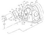
- FIG. 1is an isometric view of an exploded assembly comprised of an end cap connected to a chamber, shown in phantom, an adapter of the present invention, and inflow pipe.
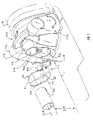
- FIG. 2is a view of the apparatus shown in FIG. 1 from the opposing axial direction, and shows how the adapter can rotate through a particular angle to change inflow pipe invert elevation.
- FIG. 3is a partial vertical plane cross section, showing how the end of an adapter fits within a hole in a buttress of the end cap.
- FIG. 4is an axial end view of an adapter inserted into the hole of a buttress of a partially shown end cap, to illustrate stop features which limit rotation of the adapter within the hole.
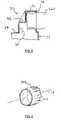
- FIG. 5is a partial vertical cross section through the inlet end of an adapter, and an inflow pipe, shown in phantom, in engagement with a interior stop.
- FIG. 6is a partial isometric view of a splined first end of an adapter.
- FIG. 1is an exploded assembly, comprising a leaching chamber end cap 20 , adapter 30 and inflow pipe 26 .
- the end capwhich is exemplary of the kind of device with which the adapter 30 of the present invention, is like that in co-pending patent application Ser. No. 10/677,771, filed on Oct. 1, 2003 by J. Burnes et al., the drawings and specification of which are hereby incorporated by reference
- End cap 20closes off the end of phantom chamber 18 in FIG. 1 .
- Chamber 18might be about 34 inch wide at the base and about 13 inch in height.
- End cap 20has three orthogonally facing buttresses 25 , 25 L and 25 R.
- a holemay be cut in the face 56 of a buttress to provide a port for water entry.
- the hole 24is at an elevation above the base 16 of the end cap article.
- holesmay be cut in other buttresses 25 L or 25 R.
- a plastic pipeis inserted in such hole to deliver wastewater to the end cap and associated chamber.
- the locations at which pipe holes may be cut in the buttressesmay be defined by grooves which demark portions of plastic which can be cut or torn out. They are not shown here; see the aforementioned Burnes et al. application.
- the adapteris shown as it fits within hole 24 , where the pipe would ordinarily go.
- a curved saddle 57runs between ledges 56 L and 56 R on the face of buttress 25 , and supports the base of the pipe or adapter which is inserted into the hole.
- FIG. 1shows a port in the vertical face surface of the buttress 25 .
- the buttressfaces along the length axis L of the end cap, which axis corresponds with the length axis of the leaching chamber.
- FIG. 2shows the assembly of FIG. 1 (less the phantom chamber) from the opposing length axis direction.
- FIG. 1 and FIG. 2show how adapter 30 , in side view, comprises a vaguely L shape hollow molded plastic body 33 .
- Adapter 30has a first male end 34 shaped like a short piece of pipe. The male end has a central or lengthwise axis LA running through the center of the opening.
- the adapterhas a second female end 31 , where there is an opening 32 , having a central or lengthwise axis LB.
- Both axes LA and LBare called major axes. They are distinguished from any other axes, e.g., diametrical, which the ends may have.
- opening 32has a diameter which accepts a pipe having the same diameter as the male end which fits in hole 24 .
- male end 34slips into hole 24 of the end cap; and the male end may then be rotated within the opening 24 . That rotation changes the angling of the adapter body and thus the invert elevation DIH of the female end 31 and any pipe 26 inserted in opening 32 . At the highest DIH elevation, the axes are vertically aligned.
- FIG. 3is a portion of a vertical plane cross section vertical of adapter 30 inserted into the hole 24 of an end cap 20 .
- the exterior surface of the adapter male end 34has protruding dimples, tabs or the like, 38 . See also FIG. 1 .
- the protuberances 38are shaped so that, when the adapter is pushed into the hole 24 of the end cap, they push aside the resilient plastic which defines the periphery of the hole. The plastic then springs back into position and engages the protuberances, thus providing resistance to withdrawal of the adapter from the hole.
- the inward motion of the adapter into hole 34is limited by another feature, namely contact of either or both the body 33 and the molded ear 37 (described below) with the ledge(s) on the face of the buttress of the end cap. Multiple spaced apart protuberances are preferred but at least one can suffice.
- FIG. 4is an end view along axis LA, toward the exterior of the end cap buttress 56 into which an adapter has been inserted. Along with FIG. 2 , it illustrates how, when the adapter 30 is inserted into the end cap hole 24 , the adapter can be rotated through angle A, about the axis LA of the adapter male end, from a maximum offset or angled position to a maximum vertical position.
- Adapter 30is shown in vertical position in FIG. 4 .
- the axes LA and LBare vertically aligned and end 32 is at its maximum elevation relative to the base of the end cap.
- the adapteris shown in an inclined position, and in phantom 30 P in vertical position, respectively with water-delivering pipes 26 P, 26 .
- the maximum rotation position of the adapteris limited by the engagement of molded ear 37 which projects outwardly from body 33 .
- the ear 37contacts ledge 36 R of saddle 57 of the buttress.
- the left rotation maximum positionis at angle A as measured from the plane where the adapter axes are vertically aligned. That limit position results from engagement of a molded indent 35 on the adapter with ledge 36 L of the end cap buttress.
- the indentis functionally analogous to ear 37 .
- Other configuration of cooperating molded features on the end cap and adaptermay be used to accomplish the purposes of limiting rotation in each direction.
- the parallel axes LA and LBare vertically unaligned. They lie in an inclined plane, and the second end axis is higher than the first end.
- the elevation of axis LB and hole 32 at the second endis less than when the axes are vertically aligned, and greater than the elevation of the end cap hole 24 relative to the base of the end cap.
- the male endmay have molded external spline features or a non-circular shape, and the plastic around hole 24 may have mating features.
- FIG. 6is a fragmentary view of the first end 34 A of an adapter having raised spline portions 62 .
- the exterior of the first endmay have a polygon shape, e.g., a octagon, and the hole or port may have a mating configuration. With such non-circular exterior shapes, when the adapter is inserted into the hole at one of the selected angular orientations, the adapter will not rotate.
- the means for limiting rotationis proximate the first end, and may be integral with the first end, as is the case with splines, or may be a projection or recess in the body of the adapter.
- each limiting rotation in one directionare preferred.
- Other embodimentsare within contemplation.
- One stop, for instance, limiting rotation when the axes are unalignedcan be used. The installer can then judge when the axes are vertically aligned, for maximum invert height. Likewise, no stops can be used and the installer can use measuring devices or judgment, securing the adapter in position as desired with fasteners.
- one protuberance on the adaptercan engage two spaced apart features on the article, so rotation in both directions is limited.
- the invert elevation DIH for a pipeis highest, at about 10 inch.
- the invert elevation of a pipe fitted in hole 24is about 8 inch.
- the invert elevation for an end capcan be chosen positively to be 8, 9 or 10 inches. If desired, intermediate elevations between 9 and 11 inches can be selected by use of a fastener.
- Adapters which have different angular ranges, or which have different body lengths, to provide more or less range of elevation changeare within contemplation.
- the adapter and stopscan be shaped so the axes cannot be made fully vertical; or so the axes can be made to lie in the horizontal plane.
- the adapter 30has another feature. As shown in FIG. 2 and the partial vertical center plane cross section of the adapter in FIG. 5 , female end 31 has a buttress 46 which projects into the interior hollow of the adapter body, to limit the extent to which pipe 26 can move lengthwise into opening 32 . In FIG. 5 , phantom pipe 26 B, is shown inserted into the opening 32 and in contact with molded buttress 46 . The buttress acts as a stop, to keep pipe 26 P a sufficient distance from the interior of body 33 , to thus avoid inhibiting of water flow. Other molded features on the interior of the female end of the adapter, such as a multiplicity of inwardly projecting tabs, may be employed for the same stop-purpose.
- the adaptermay have greater overall axial length than described above.
- the adapter female end and or male endmay extend lengthwise, so that the adapter has a nominal Z-shape when in place and viewed from the side.
- an adaptermay have first and second ends which are respectively female and male, or which ends are the same.
- Such configurationmay be suited to the devices and piping with which the adapter interconnects.
- the device to which the adapter connectsmay have a male port like a pipe stub, rather than a hole (female port).
- the diameters of the first and second endsare preferably the same, i.e., so that male end of a first adapter will fit within the second female end of an identical second adapter, they may be dissimilar.
- the adapteris preferably made by common molding, for instance injection molding, of a thermoplastic such as high density polyethylene or polypropylene. Other materials of construction may be employed.
- an adapter of the present inventionmay be used with any other device having a water-entry port above the elevation of the base.
- the adaptermay be connected to a buttress or fitting on the side or end of a leaching chamber, to another kind of chamber, to a distribution box or to an accessory for any of them.
- the adaptermay be used with a leaching chamber and end plate of the type shown in U.S. Pat. No. 5,401,116 of Nichols et al.
- the adapter of the present inventionwas conceived in connection with needs described in the Background, for use with water dispersing devices, in particular for providing a chosen invert elevation within a predetermined range. In special situations, the adapter may be used at the exit ends of such kinds of devices.
- the inventionmay be used with other fluid handling devices where analogous needs for changing the elevation of the inflow or outflow pipe are presented.
Landscapes
- Engineering & Computer Science (AREA)
- General Engineering & Computer Science (AREA)
- Mechanical Engineering (AREA)
- Health & Medical Sciences (AREA)
- Life Sciences & Earth Sciences (AREA)
- Hydrology & Water Resources (AREA)
- Public Health (AREA)
- Water Supply & Treatment (AREA)
- Underground Structures, Protecting, Testing And Restoring Foundations (AREA)
Abstract
Description
Claims (17)
Priority Applications (1)
| Application Number | Priority Date | Filing Date | Title |
|---|---|---|---|
| US11/280,705US7273330B1 (en) | 2005-11-16 | 2005-11-16 | Invert elevation-change adapter |
Applications Claiming Priority (1)
| Application Number | Priority Date | Filing Date | Title |
|---|---|---|---|
| US11/280,705US7273330B1 (en) | 2005-11-16 | 2005-11-16 | Invert elevation-change adapter |
Publications (1)
| Publication Number | Publication Date |
|---|---|
| US7273330B1true US7273330B1 (en) | 2007-09-25 |
Family
ID=38519925
Family Applications (1)
| Application Number | Title | Priority Date | Filing Date |
|---|---|---|---|
| US11/280,705ActiveUS7273330B1 (en) | 2005-11-16 | 2005-11-16 | Invert elevation-change adapter |
Country Status (1)
| Country | Link |
|---|---|
| US (1) | US7273330B1 (en) |
Cited By (14)
| Publication number | Priority date | Publication date | Assignee | Title |
|---|---|---|---|---|
| US20080240859A1 (en)* | 2007-03-29 | 2008-10-02 | Rehbein Environmental Solutions, Inc. | Subsurface fluid distribution apparatus |
| US20090220302A1 (en)* | 2008-02-13 | 2009-09-03 | Cobb Daniel P | Plastic detention chamber for stormwater runoff and related system and methods |
| US20090232600A1 (en)* | 2008-03-14 | 2009-09-17 | Kim Chang Z | Leach line and chamber combined system |
| US20100006489A1 (en)* | 2008-07-08 | 2010-01-14 | Soil Horizons, Inc. | Wastewater flow diverter |
| US20100059430A1 (en)* | 2008-09-11 | 2010-03-11 | Adams David R | Stormwater chamber detention system |
| US10442617B1 (en) | 2013-07-26 | 2019-10-15 | Infiltrator Water Technologies Llc | Multi-ring plastic storage tanks and risers |
| US11028569B2 (en)* | 2018-10-30 | 2021-06-08 | Advanced Drainage Systems, Inc. | Systems, apparatus, and methods for maintenance of stormwater management systems |
| US11427400B2 (en) | 2014-07-28 | 2022-08-30 | Infiltrator Water Technologies Llc | Taper-wall riser with tab connectors |
| US11795679B2 (en) | 2021-07-19 | 2023-10-24 | Prinsco, Inc. | Asymmetric leaching chamber for onsite wastewater management system |
| US20230340770A1 (en)* | 2018-07-27 | 2023-10-26 | Advanced Drainage Systems, Inc. | End caps for stormwater chambers and methods of making same |
| USD1036617S1 (en) | 2022-02-17 | 2024-07-23 | Prinsco, Inc. | Septic chamber end cap |
| USD1036616S1 (en) | 2022-02-17 | 2024-07-23 | Prinsco, Inc. | Septic chamber |
| US12065821B2 (en) | 2018-10-30 | 2024-08-20 | Advanced Drainage Systems, Inc. | Systems, apparatus, and methods for maintenance of stormwater management systems |
| USD1053304S1 (en) | 2022-02-17 | 2024-12-03 | Prinsco, Inc. | Septic chamber |
Citations (8)
| Publication number | Priority date | Publication date | Assignee | Title |
|---|---|---|---|---|
| US5017041A (en) | 1989-04-24 | 1991-05-21 | Infiltrator Systems Inc. | Leaching system conduit with high rigidity joint |
| US5087151A (en)* | 1989-01-30 | 1992-02-11 | Ditullio Robert J | Drainage system |
| US5556231A (en)* | 1994-09-01 | 1996-09-17 | Hancor, Inc. | Severable leaching chamber with end cap |
| US5839844A (en) | 1995-06-12 | 1998-11-24 | Infiltrator Systems, Inc. | Leaching chamber endplate |
| US5921711A (en)* | 1997-01-23 | 1999-07-13 | Sipaila; Jonas Z. | Subsurface fluid distribution apparatus and method |
| US6602023B2 (en)* | 1999-12-22 | 2003-08-05 | Infiltrator Systems, Inc. | Leaching chamber endplate |
| US6698975B1 (en)* | 2002-08-27 | 2004-03-02 | Hancor, Inc. | Coupling structure for a leaching chamber |
| US7008138B2 (en)* | 2003-10-01 | 2006-03-07 | Infiltrator Systems Inc | Faceted end cap for leaching chamber |
- 2005
- 2005-11-16USUS11/280,705patent/US7273330B1/enactiveActive
Patent Citations (8)
| Publication number | Priority date | Publication date | Assignee | Title |
|---|---|---|---|---|
| US5087151A (en)* | 1989-01-30 | 1992-02-11 | Ditullio Robert J | Drainage system |
| US5017041A (en) | 1989-04-24 | 1991-05-21 | Infiltrator Systems Inc. | Leaching system conduit with high rigidity joint |
| US5556231A (en)* | 1994-09-01 | 1996-09-17 | Hancor, Inc. | Severable leaching chamber with end cap |
| US5839844A (en) | 1995-06-12 | 1998-11-24 | Infiltrator Systems, Inc. | Leaching chamber endplate |
| US5921711A (en)* | 1997-01-23 | 1999-07-13 | Sipaila; Jonas Z. | Subsurface fluid distribution apparatus and method |
| US6602023B2 (en)* | 1999-12-22 | 2003-08-05 | Infiltrator Systems, Inc. | Leaching chamber endplate |
| US6698975B1 (en)* | 2002-08-27 | 2004-03-02 | Hancor, Inc. | Coupling structure for a leaching chamber |
| US7008138B2 (en)* | 2003-10-01 | 2006-03-07 | Infiltrator Systems Inc | Faceted end cap for leaching chamber |
Cited By (19)
| Publication number | Priority date | Publication date | Assignee | Title |
|---|---|---|---|---|
| US7517172B2 (en)* | 2007-03-29 | 2009-04-14 | Rehbein Environmental Solutions, Inc. | Subsurface fluid distribution apparatus |
| US20080240859A1 (en)* | 2007-03-29 | 2008-10-02 | Rehbein Environmental Solutions, Inc. | Subsurface fluid distribution apparatus |
| US8491224B2 (en) | 2008-02-13 | 2013-07-23 | Contech Engineered Solutions LLC | Plastic detention chamber for stormwater runoff and related system and methods |
| US20090220302A1 (en)* | 2008-02-13 | 2009-09-03 | Cobb Daniel P | Plastic detention chamber for stormwater runoff and related system and methods |
| US20090232600A1 (en)* | 2008-03-14 | 2009-09-17 | Kim Chang Z | Leach line and chamber combined system |
| US20100006489A1 (en)* | 2008-07-08 | 2010-01-14 | Soil Horizons, Inc. | Wastewater flow diverter |
| US7744756B2 (en)* | 2008-07-08 | 2010-06-29 | Soil Horizons, Inc. | Wastewater flow diverter |
| US8147688B2 (en) | 2008-09-11 | 2012-04-03 | Contech Engineered Solutions LLC | Stormwater chamber detention system |
| US20100059430A1 (en)* | 2008-09-11 | 2010-03-11 | Adams David R | Stormwater chamber detention system |
| US10442617B1 (en) | 2013-07-26 | 2019-10-15 | Infiltrator Water Technologies Llc | Multi-ring plastic storage tanks and risers |
| US11427400B2 (en) | 2014-07-28 | 2022-08-30 | Infiltrator Water Technologies Llc | Taper-wall riser with tab connectors |
| US20230340770A1 (en)* | 2018-07-27 | 2023-10-26 | Advanced Drainage Systems, Inc. | End caps for stormwater chambers and methods of making same |
| US12071758B2 (en)* | 2018-07-27 | 2024-08-27 | Advanced Drainage Systems, Inc. | End caps for stormwater chambers and methods of making same |
| US12065821B2 (en) | 2018-10-30 | 2024-08-20 | Advanced Drainage Systems, Inc. | Systems, apparatus, and methods for maintenance of stormwater management systems |
| US11028569B2 (en)* | 2018-10-30 | 2021-06-08 | Advanced Drainage Systems, Inc. | Systems, apparatus, and methods for maintenance of stormwater management systems |
| US11795679B2 (en) | 2021-07-19 | 2023-10-24 | Prinsco, Inc. | Asymmetric leaching chamber for onsite wastewater management system |
| USD1036616S1 (en) | 2022-02-17 | 2024-07-23 | Prinsco, Inc. | Septic chamber |
| USD1036617S1 (en) | 2022-02-17 | 2024-07-23 | Prinsco, Inc. | Septic chamber end cap |
| USD1053304S1 (en) | 2022-02-17 | 2024-12-03 | Prinsco, Inc. | Septic chamber |
Similar Documents
| Publication | Publication Date | Title |
|---|---|---|
| US7273330B1 (en) | Invert elevation-change adapter | |
| US8337119B2 (en) | Leaching chamber having a dome shaped end portion for pivotably connecting with a second chamber end portion | |
| US7871109B1 (en) | Drain basin with pipe couplings | |
| US7237981B1 (en) | End cap having integral pipe stub for use with stormwater chamber | |
| US5234018A (en) | Sewer check valve and cleanout apparatus | |
| US5645367A (en) | Drainage system having an embedded conduit connector | |
| US7008138B2 (en) | Faceted end cap for leaching chamber | |
| US7140388B2 (en) | Dual ball valve air vent valve | |
| US5029612A (en) | Auxiliary water supply barrel | |
| US20070236002A1 (en) | Drain, particularly for use in a gravity-fed drainage system | |
| US9988817B2 (en) | Gate valve downspout diverter for rainwater collection | |
| CN211345668U (en) | Water distributor system | |
| US20220297269A1 (en) | Adaptor for use between a stop valve and extension wrench | |
| US4882045A (en) | Dispersal apparatus with rotation valving | |
| US9109342B1 (en) | Manhole | |
| CA2477915C (en) | Improved manhole base | |
| US20060042174A1 (en) | Modular riser base | |
| US20050081926A1 (en) | First flush water diverter | |
| US9487934B1 (en) | Frost-free hydrant drainage system | |
| CA2656973A1 (en) | Heating apparatus for installation on rooftop end of sewer vent pipe | |
| US20170254466A1 (en) | Coupling apparatus for a floor drain and method of use | |
| CN110158713A (en) | Floor drain connecting tube | |
| US12379055B2 (en) | Check valve connector system | |
| TW201114999A (en) | A pressurised rain water drainage outlet | |
| CN110185849A (en) | A kind of automatically cleaning abnormity solid wall pipe and its installation method |
Legal Events
| Date | Code | Title | Description |
|---|---|---|---|
| AS | Assignment | Owner name:INFILTRATOR SYSTEMS, INC., CONNECTICUT Free format text:ASSIGNMENT OF ASSIGNORS INTEREST;ASSIGNORS:BROCHU, RONALD P.;BURNES, JAMES J.;REEL/FRAME:017520/0906;SIGNING DATES FROM 20051117 TO 20051128 | |
| AS | Assignment | Owner name:MERRILL LYNCH CAPITAL, A DIVISION OF MERRILL LYNCH Free format text:SECURITY AGREEMENT;ASSIGNOR:INFILTRATOR SYSTEMS, INC.;REEL/FRAME:018454/0896 Effective date:20061031 Owner name:MERRILL LYNCH CAPITAL, A DIVISION OF MERRILL LYNCH Free format text:SECURITY AGREEMENT;ASSIGNOR:INFILTRATOR SYSTEMS, INC.;REEL/FRAME:018463/0060 Effective date:20061031 | |
| AS | Assignment | Owner name:AMERICAN CAPITAL FINANCIAL SERVICES, INC., MARYLAN Free format text:SECURITY AGREEMENT;ASSIGNOR:INFILTRATOR SYSTEMS, INC;REEL/FRAME:018463/0693 Effective date:20061031 | |
| FEPP | Fee payment procedure | Free format text:PAYOR NUMBER ASSIGNED (ORIGINAL EVENT CODE: ASPN); ENTITY STATUS OF PATENT OWNER: LARGE ENTITY | |
| STCF | Information on status: patent grant | Free format text:PATENTED CASE | |
| AS | Assignment | Owner name:AMERICAN CAPITAL FINANCIAL SERVICES, INC., MARYLAN Free format text:SECURITY AGREEMENT;ASSIGNOR:INFILTRATOR SYSTEMS, INC.;REEL/FRAME:021773/0179 Effective date:20081031 | |
| REMI | Maintenance fee reminder mailed | ||
| FPAY | Fee payment | Year of fee payment:4 | |
| SULP | Surcharge for late payment | ||
| FPAY | Fee payment | Year of fee payment:8 | |
| AS | Assignment | Owner name:INFILTRATOR SYSTEMS, INC., CONNECTICUT Free format text:RELEASE BY SECURED PARTY;ASSIGNOR:AMERICAN CAPITAL, LTD.;REEL/FRAME:035749/0405 Effective date:20150511 | |
| AS | Assignment | Owner name:INFILTRATOR SYSTEMS, INC. (FORMERLY KNOWN AS WATER Free format text:RELEASE BY SECURED PARTY;ASSIGNOR:GE BUSINESS FINANCIAL SERVICES, INC. (FORMERLY KNOWN AS MERRILL LYNCH CAPITAL, A DIVISION OF MERRILL LYNCH BUSINESS FINANCIAL SERVICES, INC.);REEL/FRAME:035745/0166 Effective date:20150528 Owner name:INFILTRATOR SYSTEMS, INC. (FORMERLY KNOWN AS WATER Free format text:RELEASE BY SECURED PARTY;ASSIGNOR:GE BUSINESS FINANCIAL SERVICES INC. (FORMERLY KNOWN AS MERRILL LYNCH BUSINESS FINANCIAL SERVICES INC.);REEL/FRAME:035797/0837 Effective date:20150528 Owner name:EZFLOW, L.P. (FORMERLY KNOWN AS RING INDUSTRIAL GR Free format text:RELEASE BY SECURED PARTY;ASSIGNOR:GE BUSINESS FINANCIAL SERVICES INC. (FORMERLY KNOWN AS MERRILL LYNCH BUSINESS FINANCIAL SERVICES INC.);REEL/FRAME:035797/0837 Effective date:20150528 | |
| AS | Assignment | Owner name:DEUTSCHE BANK AG NEW YORK BRANCH, NEW YORK Free format text:SECURITY INTEREST;ASSIGNORS:ISI POLYETHYLENE SOLUTIONS, LLC;EZFLOW, L.P.;INFILTRATOR WATER TECHNOLOGIES, LLC;REEL/FRAME:036044/0562 Effective date:20150527 Owner name:DEUTSCHE BANK AG NEW YORK BRANCH, NEW YORK Free format text:SECURITY INTEREST;ASSIGNORS:ISI POLYETHYLENE SOLUTIONS, LLC;EZFLOW, L.P.;INFILTRATOR WATER TECHNOLOGIES, LLC;REEL/FRAME:036044/0627 Effective date:20150527 | |
| AS | Assignment | Owner name:INFILTRATOR WATER TECHNOLOGIES, LLC, CONNECTICUT Free format text:MERGER AND CHANGE OF NAME;ASSIGNORS:INFILTRATOR SYSTEMS, INC;INFILTRATOR WATER TECHNOLOGIES, LLC;REEL/FRAME:036387/0435 Effective date:20150527 Owner name:INFILTRATOR WATER TECHNOLOGIES, LLC, CONNECTICUT Free format text:MERGER AND CHANGE OF NAME;ASSIGNORS:INFILTRATOR SYSTEMS, INC;INFILTRATOR WATER TECHNOLOGIES, LLC;REEL/FRAME:036387/0540 Effective date:20150527 | |
| AS | Assignment | Owner name:EZFLOW, L.P., CONNECTICUT Free format text:RELEASE BY SECURED PARTY;ASSIGNOR:DEUTSCHE BANK AG NEW YORK;REEL/FRAME:041777/0638 Effective date:20170217 Owner name:INFILTRATOR WATER TECHNOLOGIES, LLC, CONNECTICUT Free format text:RELEASE BY SECURED PARTY;ASSIGNOR:DEUTSCHE BANK AG NEW YORK;REEL/FRAME:041777/0638 Effective date:20170217 Owner name:ISI POLYETHYLENE SOLUTIONS, LLC, CONNECTICUT Free format text:RELEASE BY SECURED PARTY;ASSIGNOR:DEUTSCHE BANK AG NEW YORK;REEL/FRAME:041777/0638 Effective date:20170217 | |
| MAFP | Maintenance fee payment | Free format text:PAYMENT OF MAINTENANCE FEE, 12TH YEAR, LARGE ENTITY (ORIGINAL EVENT CODE: M1553); ENTITY STATUS OF PATENT OWNER: LARGE ENTITY Year of fee payment:12 | |
| AS | Assignment | Owner name:INFILTRATOR WATER TECHNOLOGIES, LLC, CONNECTICUT Free format text:RELEASE OF SECURITY INTERESTS IN PATENTS (RELEASES RF 036044/0562);ASSIGNOR:DEUTSCHE BANK AG NEW YORK BRANCH, AS COLLATERAL AGENT;REEL/FRAME:049942/0332 Effective date:20190731 Owner name:ISI POLYETHYLENE SOLUTIONS, LLC, CONNECTICUT Free format text:RELEASE OF SECURITY INTERESTS IN PATENTS (RELEASES RF 036044/0562);ASSIGNOR:DEUTSCHE BANK AG NEW YORK BRANCH, AS COLLATERAL AGENT;REEL/FRAME:049942/0332 Effective date:20190731 Owner name:EZFLOW, L.P., CONNECTICUT Free format text:RELEASE OF SECURITY INTERESTS IN PATENTS (RELEASES RF 036044/0562);ASSIGNOR:DEUTSCHE BANK AG NEW YORK BRANCH, AS COLLATERAL AGENT;REEL/FRAME:049942/0332 Effective date:20190731 | |
| AS | Assignment | Owner name:BARCLAYS BANK PLC, AS ADMINISTRATIVE AGENT, NEW YO Free format text:SECURITY INTEREST;ASSIGNOR:INFILTRATOR WATER TECHNOLOGIES, LLC;REEL/FRAME:051287/0286 Effective date:20191213 Owner name:BARCLAYS BANK PLC, AS ADMINISTRATIVE AGENT, NEW YORK Free format text:SECURITY INTEREST;ASSIGNOR:INFILTRATOR WATER TECHNOLOGIES, LLC;REEL/FRAME:051287/0286 Effective date:20191213 |