US7272537B2 - Spout for dispensing liquid from a liquid container - Google Patents
Spout for dispensing liquid from a liquid containerDownload PDFInfo
- Publication number
- US7272537B2 US7272537B2US10/845,395US84539504AUS7272537B2US 7272537 B2US7272537 B2US 7272537B2US 84539504 AUS84539504 AUS 84539504AUS 7272537 B2US7272537 B2US 7272537B2
- Authority
- US
- United States
- Prior art keywords
- spout
- electronic component
- pour
- liquid
- liquid container
- Prior art date
- Legal status (The legal status is an assumption and is not a legal conclusion. Google has not performed a legal analysis and makes no representation as to the accuracy of the status listed.)
- Expired - Lifetime
Links
Images


Classifications
- B—PERFORMING OPERATIONS; TRANSPORTING
- B67—OPENING, CLOSING OR CLEANING BOTTLES, JARS OR SIMILAR CONTAINERS; LIQUID HANDLING
- B67D—DISPENSING, DELIVERING OR TRANSFERRING LIQUIDS, NOT OTHERWISE PROVIDED FOR
- B67D1/00—Apparatus or devices for dispensing beverages on draught
- B67D1/08—Details
- B67D1/12—Flow or pressure control devices or systems, e.g. valves, gas pressure control, level control in storage containers
- B67D1/1202—Flow control, e.g. for controlling total amount or mixture ratio of liquids to be dispensed
- B67D1/1204—Flow control, e.g. for controlling total amount or mixture ratio of liquids to be dispensed for ratio control purposes
- B67D1/1206—Flow detectors
- B—PERFORMING OPERATIONS; TRANSPORTING
- B67—OPENING, CLOSING OR CLEANING BOTTLES, JARS OR SIMILAR CONTAINERS; LIQUID HANDLING
- B67D—DISPENSING, DELIVERING OR TRANSFERRING LIQUIDS, NOT OTHERWISE PROVIDED FOR
- B67D1/00—Apparatus or devices for dispensing beverages on draught
- B—PERFORMING OPERATIONS; TRANSPORTING
- B67—OPENING, CLOSING OR CLEANING BOTTLES, JARS OR SIMILAR CONTAINERS; LIQUID HANDLING
- B67D—DISPENSING, DELIVERING OR TRANSFERRING LIQUIDS, NOT OTHERWISE PROVIDED FOR
- B67D1/00—Apparatus or devices for dispensing beverages on draught
- B67D1/08—Details
- B67D1/0878—Safety, warning or controlling devices
- B67D1/0881—Means for counting the doses of dispensed liquid
- B—PERFORMING OPERATIONS; TRANSPORTING
- B67—OPENING, CLOSING OR CLEANING BOTTLES, JARS OR SIMILAR CONTAINERS; LIQUID HANDLING
- B67D—DISPENSING, DELIVERING OR TRANSFERRING LIQUIDS, NOT OTHERWISE PROVIDED FOR
- B67D1/00—Apparatus or devices for dispensing beverages on draught
- B67D1/08—Details
- B67D1/0888—Means comprising electronic circuitry (e.g. control panels, switching or controlling means)
- B—PERFORMING OPERATIONS; TRANSPORTING
- B67—OPENING, CLOSING OR CLEANING BOTTLES, JARS OR SIMILAR CONTAINERS; LIQUID HANDLING
- B67D—DISPENSING, DELIVERING OR TRANSFERRING LIQUIDS, NOT OTHERWISE PROVIDED FOR
- B67D1/00—Apparatus or devices for dispensing beverages on draught
- B67D1/08—Details
- B67D1/12—Flow or pressure control devices or systems, e.g. valves, gas pressure control, level control in storage containers
- B67D1/1202—Flow control, e.g. for controlling total amount or mixture ratio of liquids to be dispensed
- B67D1/1204—Flow control, e.g. for controlling total amount or mixture ratio of liquids to be dispensed for ratio control purposes
- B67D1/1206—Flow detectors
- B67D1/1209—Flow detectors combined with a timer
- B—PERFORMING OPERATIONS; TRANSPORTING
- B67—OPENING, CLOSING OR CLEANING BOTTLES, JARS OR SIMILAR CONTAINERS; LIQUID HANDLING
- B67D—DISPENSING, DELIVERING OR TRANSFERRING LIQUIDS, NOT OTHERWISE PROVIDED FOR
- B67D1/00—Apparatus or devices for dispensing beverages on draught
- B67D1/08—Details
- B67D1/12—Flow or pressure control devices or systems, e.g. valves, gas pressure control, level control in storage containers
- B67D1/1202—Flow control, e.g. for controlling total amount or mixture ratio of liquids to be dispensed
- B67D1/1204—Flow control, e.g. for controlling total amount or mixture ratio of liquids to be dispensed for ratio control purposes
- B67D1/1211—Flow rate sensor
- B—PERFORMING OPERATIONS; TRANSPORTING
- B67—OPENING, CLOSING OR CLEANING BOTTLES, JARS OR SIMILAR CONTAINERS; LIQUID HANDLING
- B67D—DISPENSING, DELIVERING OR TRANSFERRING LIQUIDS, NOT OTHERWISE PROVIDED FOR
- B67D3/00—Apparatus or devices for controlling flow of liquids under gravity from storage containers for dispensing purposes
- B67D3/0003—Apparatus or devices for controlling flow of liquids under gravity from storage containers for dispensing purposes provided with automatic fluid control means
- B67D3/0006—Apparatus or devices for controlling flow of liquids under gravity from storage containers for dispensing purposes provided with automatic fluid control means responsive to coded information provided on the neck or spout of the storage container, e.g. bar-code, magnets or transponder
- B—PERFORMING OPERATIONS; TRANSPORTING
- B67—OPENING, CLOSING OR CLEANING BOTTLES, JARS OR SIMILAR CONTAINERS; LIQUID HANDLING
- B67D—DISPENSING, DELIVERING OR TRANSFERRING LIQUIDS, NOT OTHERWISE PROVIDED FOR
- B67D3/00—Apparatus or devices for controlling flow of liquids under gravity from storage containers for dispensing purposes
- B67D3/0041—Apparatus or devices for controlling flow of liquids under gravity from storage containers for dispensing purposes with provisions for metering the liquid to be dispensed
- B—PERFORMING OPERATIONS; TRANSPORTING
- B67—OPENING, CLOSING OR CLEANING BOTTLES, JARS OR SIMILAR CONTAINERS; LIQUID HANDLING
- B67D—DISPENSING, DELIVERING OR TRANSFERRING LIQUIDS, NOT OTHERWISE PROVIDED FOR
- B67D3/00—Apparatus or devices for controlling flow of liquids under gravity from storage containers for dispensing purposes
- B67D3/0051—Apparatus or devices for controlling flow of liquids under gravity from storage containers for dispensing purposes dispensing by tilting
- B—PERFORMING OPERATIONS; TRANSPORTING
- B67—OPENING, CLOSING OR CLEANING BOTTLES, JARS OR SIMILAR CONTAINERS; LIQUID HANDLING
- B67D—DISPENSING, DELIVERING OR TRANSFERRING LIQUIDS, NOT OTHERWISE PROVIDED FOR
- B67D3/00—Apparatus or devices for controlling flow of liquids under gravity from storage containers for dispensing purposes
- B67D3/0054—Mounting or arrangements of dispensing apparatus in shops or bar counters
- G—PHYSICS
- G01—MEASURING; TESTING
- G01F—MEASURING VOLUME, VOLUME FLOW, MASS FLOW OR LIQUID LEVEL; METERING BY VOLUME
- G01F1/00—Measuring the volume flow or mass flow of fluid or fluent solid material wherein the fluid passes through a meter in a continuous flow
- G—PHYSICS
- G01—MEASURING; TESTING
- G01F—MEASURING VOLUME, VOLUME FLOW, MASS FLOW OR LIQUID LEVEL; METERING BY VOLUME
- G01F13/00—Apparatus for measuring by volume and delivering fluids or fluent solid materials, not provided for in the preceding groups
- G01F13/006—Apparatus for measuring by volume and delivering fluids or fluent solid materials, not provided for in the preceding groups measuring volume in function of time
- G—PHYSICS
- G01—MEASURING; TESTING
- G01F—MEASURING VOLUME, VOLUME FLOW, MASS FLOW OR LIQUID LEVEL; METERING BY VOLUME
- G01F9/00—Measuring volume flow relative to another variable, e.g. of liquid fuel for an engine
- G01F9/008—Measuring volume flow relative to another variable, e.g. of liquid fuel for an engine where the other variable is the flight or running time
- G—PHYSICS
- G06—COMPUTING OR CALCULATING; COUNTING
- G06Q—INFORMATION AND COMMUNICATION TECHNOLOGY [ICT] SPECIALLY ADAPTED FOR ADMINISTRATIVE, COMMERCIAL, FINANCIAL, MANAGERIAL OR SUPERVISORY PURPOSES; SYSTEMS OR METHODS SPECIALLY ADAPTED FOR ADMINISTRATIVE, COMMERCIAL, FINANCIAL, MANAGERIAL OR SUPERVISORY PURPOSES, NOT OTHERWISE PROVIDED FOR
- G06Q30/00—Commerce
- G06Q30/02—Marketing; Price estimation or determination; Fundraising
- G06Q30/0201—Market modelling; Market analysis; Collecting market data
- G06Q30/0204—Market segmentation
- G06Q30/0205—Market segmentation based on location or geographical consideration
- B—PERFORMING OPERATIONS; TRANSPORTING
- B67—OPENING, CLOSING OR CLEANING BOTTLES, JARS OR SIMILAR CONTAINERS; LIQUID HANDLING
- B67D—DISPENSING, DELIVERING OR TRANSFERRING LIQUIDS, NOT OTHERWISE PROVIDED FOR
- B67D2210/00—Indexing scheme relating to aspects and details of apparatus or devices for dispensing beverages on draught or for controlling flow of liquids under gravity from storage containers for dispensing purposes
- B67D2210/00028—Constructional details
- B67D2210/00081—Constructional details related to bartenders
- B67D2210/00089—Remote control means, e.g. by electromagnetic signals
- B—PERFORMING OPERATIONS; TRANSPORTING
- B67—OPENING, CLOSING OR CLEANING BOTTLES, JARS OR SIMILAR CONTAINERS; LIQUID HANDLING
- B67D—DISPENSING, DELIVERING OR TRANSFERRING LIQUIDS, NOT OTHERWISE PROVIDED FOR
- B67D2210/00—Indexing scheme relating to aspects and details of apparatus or devices for dispensing beverages on draught or for controlling flow of liquids under gravity from storage containers for dispensing purposes
- B67D2210/00028—Constructional details
- B67D2210/00081—Constructional details related to bartenders
- B67D2210/00091—Bar management means
- B—PERFORMING OPERATIONS; TRANSPORTING
- B67—OPENING, CLOSING OR CLEANING BOTTLES, JARS OR SIMILAR CONTAINERS; LIQUID HANDLING
- B67D—DISPENSING, DELIVERING OR TRANSFERRING LIQUIDS, NOT OTHERWISE PROVIDED FOR
- B67D2210/00—Indexing scheme relating to aspects and details of apparatus or devices for dispensing beverages on draught or for controlling flow of liquids under gravity from storage containers for dispensing purposes
- B67D2210/00028—Constructional details
- B67D2210/00094—Ergonomics
Definitions
- the inventionis directed towards method, apparatus, and system for monitoring amount of liquid poured from liquid containers.
- the amount of liquids dispensed from liquid containersneed to be monitored for many endeavors today. For instance, the management of establishments such as bars and taverns have long found it necessary to carefully monitor the relationship between liquor dispensed and receipts by controlling the quantity of liquor dispensed from a specific bottle and recording the sale.
- a few systemshave been proposed to date for measuring and recording the amount of liquid dispensed from liquid containers.
- One such systemincludes a spout that is configured to attach to an opening of a liquid container. This spout also uses a portion-control mechanism to control the desired amount of liquid poured from the liquid container.
- the spoutincludes a radio transmitter for emitting signals containing activity information.
- a receiverreceives the transmitted signals, and provides these signals to a computer at the establishment that processes the signals into text for viewing.
- portion-control mechanismsrequire manual activation and are at times bulky.
- a compact free-pour apparatusthat measures the amount of dispensed liquid in an unobtrusive fashion without requiring manual activation.
- Some embodiments of the inventionprovide a system for monitoring liquid consumption at one or more establishments.
- the systemincludes one or more spouts and a local computer.
- Each spoutis mounted on a liquid container.
- each spoutgenerates data regarding the amount of liquid poured from the spout's container.
- the local computer at each establishmentcollects data generated by the spouts at the establishment.
- a wireless networklinks the local computer and the spouts at each establishment.
- the systemalso includes an external computer that gathers the data collected by the local computers of the establishments monitored by the system.
- the external computeris located outside of all the establishments, while in other embodiments this computer is located within one of the establishments.
- each local computercollects raw data from the spouts and passes this raw data to the external computer, which converts this raw data into the actual amount dispensed from the liquid containers.
- a local computermight generate the actual amount dispensed from the liquid container and pass this amount to the external computer.
- a spoutmight generate the actual amount dispensed from the liquid container and pass this amount to the local computer.
- Some embodiments of the inventionprovide a free-pour spout.
- This spoutmounts on an open orifice of a liquid container and measures the amount of liquid poured from the liquid container.
- This spouthas a housing and a passageway defined within the housing. It also has a detection circuit that detects fluid flow through the passageway.
- this spouthas a measuring circuit that generates data relating to fluid flow when the detection circuit detects fluid flow through the passageway.
- the detection circuitincludes a motion circuit that detects when the spout is tilted by at least a first angle.
- the measuring circuitonce the motion circuit detects that the spout is tilted by at least the first angle, the measuring circuit generates a time measurement when the spout remains tilted by at least the first angle for a threshold time period. This time measurement represents an estimate of the time that liquid was flowing through the passageway.
- the time measurementis derived from at least two time intervals relating to fluid flow. For instance, some embodiments generate the time measurement as the weighted or unweighted sum of two time intervals relating to fluid flow. In some embodiments, one time interval is a pour-initiation period during which fluid begins to pour through the spout's passageway, and another time interval is a full-pour period during which fluid freely pours through the spout's passageway.
- the spout's passagewaydesign the spout's passageway to have certain dimensional attributes that ensure laminar fluid flow.
- the spout's passagewayhas a bent cylindrical shape that has a length L (also referred to as height) and a circular cross section with a diameter D, where the ratio of L and D is less than or equal to 20.
- Lalso referred to as height
- Ddiameter
- One of ordinary skillwill realize that other embodiments might use different shaped passageways (e.g., might use non-circular cylindrical passageways that have elliptical cross sections or polygonal cross sections). These embodiments could ensure laminar fluid flow similarly by selecting a particular set of dimensions (e.g., selecting a particular height and cross-section size) for the passageway.
- the motion circuitgenerates a first signal that is active when the spout is tilted by at least the first angle.
- the motion circuitincludes a tilt switch that outputs the first signal. This tilt switch closes when the spout is titled by at least a first angle (e.g., in some embodiments, the coordinate axes of the tilt switch and the spout are aligned, and the tilt switch closes when the spout and tilt switch are tilted by 90°).
- the closing of the tilt switchmakes the first signal active and the opening of the tilt switch makes the first signal inactive.
- one terminal of the tilt switchconnects to the output terminal that supplies the first signal while another terminal of the tilt switch connects to a reference voltage.
- (1) the closing of the tilt switchpulls the first signal to the reference voltage, which defines the active state of the first signal, while (2) the opening of the tilt switch causes the charge on the first signal to drain to a ground state, which defines the inactive state of the first signal.
- FIG. 1illustrates a monitoring system according to some embodiments of the invention.
- FIGS. 2A–2Hpresent several different views of the exterior contour of a free-pour spout used in some embodiments of the invention.
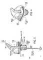
- FIG. 3presents a side-cross sectional view of the spout of FIG. 2 .
- FIG. 4presents a perspective view of the top of the spout of FIG. 2 .
- FIG. 5illustrates a block diagram of the electronic components on a PCB of the free-pour spout of FIG. 2 .
- FIG. 6illustrates a time-measurement process used by a micro-controller of the free-pour spout of FIG. 2 .
- FIG. 7illustrates the housing of the tilt switch.
- FIG. 8pictorially illustrates the types of fluid flow for different tilting angles of the free-pour spout and the tilt switch.
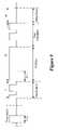
- FIG. 9presents a timing diagram that pictorially illustrates different fluid-flow periods.
- FIG. 10illustrates a process that a data processing server performs to convert the raw packet data that it receives to the actual amount of the dispensed liquid or to the actual status of the spout.
- the inventionis directed towards method, apparatus, and system for monitoring amount of liquid poured from liquid containers.
- well-known structures and devicesare shown in block diagram form in order not to obscure the description of the invention with unnecessary detail.
- numerous detailsare set forth for purpose of explanation.
- the inventionis described below by reference to the Internet, the World Wide Web (WWW) and technology related to the Internet and the WWW.
- WWWWorld Wide Web
- the same techniquescan easily be applied to other types of electronic information distribution systems.
- the inventioncan be applied to computer networks that use other data communication protocols and/or use next generation Internet protocols.
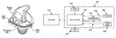
- FIG. 1illustrates a monitoring system 100 according to some embodiments of the invention.
- This systemallows an administrator to monitor liquid consumption at one or more establishments 105 (e.g., one ore more bars or taverns).
- This systemincludes several components that are located at each establishment 105 and several components that are located outside of the establishment.
- the systemincludes (1) one or more spouts 110 for attaching to openings of liquid containers, (2) a receiver 120 , (3) a computer 125 or any other data collection device or appliance, and (4) an RS232 link 130 for communicatively coupling the receiver 120 and computer 125 .
- the systemalso includes computers 135 for the administrators of the establishment. As shown in FIG. 1 , the administrator computers can be located inside or outside of the establishment. Outside of the establishment 105 , the system also includes a data processing server 145 , an application server 150 , and a database 155 . The data processing server and the application server communicatively couple respectively to the local computer 125 and the administrator computers 135 through the Internet.
- each spout 110is configured to attach to an opening of a liquid container.
- each spoutincludes a transmitter 115 and a measuring apparatus 160 .
- Each spout's measuring apparatusprovides data relating to the amount of liquid poured from the container affixed to its spout.
- the measuring apparatusescalculate the actual amount of liquid dispensed from their corresponding containers.
- the measuring apparatusesgenerate raw data relating to the amount of the dispensed liquid; as further described below, the data processing server 145 converts the raw data to the actual amount of the dispensed liquid.
- a spout's measuring apparatuscan be an in-line conductive or inductive flow meter, a portion-control mechanism, or a free-pour measurement apparatus.
- An example of an in-line flow meter that can be used in conjunction with the present inventionis Draft Sentinel Beer Monitoring Equipment of Berg Company.
- U.S. Pat. No. 6,036,055discloses an electronic spout 110 that has a portion-control mechanism, which can be used in conjunction with the present invention. The disclosure of U.S. Pat. No. 6,036,055 is incorporated herein by reference.
- a novel free-pour measurement apparatuswill be described below by reference to FIGS. 2–9 .
- the data generated by each spout's measurement apparatusis transmitted to the receiver 120 by the spout's transmitter 115 .
- the spout transmittersare radio transmitters that transmit radio signals to a radio receiver 120 .
- a spout's transmittertransmits an engage signal to the receiver each time its spout is placed on a liquid container, a disengage signal to the receiver each time its spout is removed from the liquid container, and a pour signal each time the spout's measurement apparatus detects a pour.
- the transmittertransmits each signal multiple times at random intervals when an event occurs (e.g., an engage, disengage, or pour event occurs), in order to ensure reliable reception.
- the signalincludes a data packet that contains a serial number, a sequence number, and an event identifier.
- the serial numberprovides the identity of a spout, which, as further described below, is assigned (via software) to a particular type of liquid (e.g., to a particular liquor brand) for each establishment or customer.
- the serial numberis used by the data-processing server to identify the type of liquid stored in the container attached to the spout.
- the sequence numberprovides a count of each unique event of each serial-numbered unit, and thereby differentiates the reception of different unique events from the same serial-numbered unit.
- the event identifierspecifies the type of event that has occurred. As mentioned above, the event-types are spout engage, spout disengage, and pour.
- the pour eventcan be specified by a variety of raw data. In the free-pour embodiments described below, each pour event is specified by a time-interval that is measured by the measurement apparatus of the spout.
- the receiver 120forwards each packet that it receives from the transmitters 115 to the computer 125 through the RS-232 link, which, in some embodiments, is formed by an RS-232 cable connecting the RS-232 ports of the computer and receiver.
- each transmittertransmits each signal multiple times in order to ensure reliable reception.
- the receiverdiscards the other identical copies of the packet that it receives.
- the receiver(1) stores in a table the serial number and sequence number of each packet that it forwards to the computer, and (2) discards the received packets that have serial and sequence numbers that match serial and sequence numbers recorded in the table.
- the tableis a FIFO table; hence, when it fills up, the first entry in the table is deleted in order to record the next entry.
- the computerstores the packets that it receives from the receiver in a data file.
- the computercan be a typical personal computer, workstation, or server. In some embodiments, this computer is a data-collecting “brick” with minimal or no interactions with individuals at the establishment. At pre-specified intervals (e.g., every five minutes), the computer sends through the Internet the data file with the collected packet to the data processing server 145 . The transmitted data file identifies the establishment from which the data was collected. In some embodiments, the computer 125 connects to the Internet through a dedicated high-speed connection, such as a DSL connection.
- the data-processing servereither directly connects to the Internet, or connects to the Internet through a Web Server (not shown), to receive the data files transmitted by the computer 125 .
- the data-processing serverconverts the raw packet data that it receives to the actual amount of the dispensed liquid or to the actual status of the spout. This server then stores the generated amount or status in the database 155 .
- an administrator of the establishmentcan then search the database to obtain various business-related reports, displays, or other information.
- the administratorqueries this database through the application server, which communicatively couples to the administrator's computer 135 through the Internet.
- the application server 150either directly connects to the Internet, or connects to the Internet through a Web Server (not shown).
- FIGS. 2A–2Hpresent several different views of the exterior contour of a free-pour spout used in some embodiments of the invention.
- FIG. 3presents a side-cross sectional view of this spout
- FIG. 4presents a perspective view of the top of this spout.
- the bottom portion 330 of this spoutis inserted into the top of a liquid container.
- the bottom portionincludes a cork that flexes to snuggly attach the spout to the liquid container. Different size corks can also be mounted on the bottom portion in order to allow the spout to affix to liquid containers with different sized openings.
- the spoutincludes a fluid-flow passageway 305 , a breather tube 310 , a printed circuit board (“PCB”) 315 with a number of electronic components, a battery 320 , an LED 325 , and an engage switch 340 .
- the dimensions of the fluid-flow passagewayare specifically selected to ensure laminar fluid flow of liquid when the liquid-container and hence the spout are inclined at a certain angle (e.g., 20°) past the horizontal axis of the liquid-container.
- the ratio (L/D) of the passageway's length (L) and width (or diameter D)is selected to be equal to or less than 20 in order to ensure laminar fluid flow.
- the breather tube 310When the spout is positioned on a liquid container, the breather tube 310 provides an air inlet that allows better fluid flow through the passageway 305 .
- the battery 320provides power for the electronic components of the PCB 315 .
- the LED 325is configured to turn on when the spout engages after it is firmly placed on a liquid container. In some embodiments, the LED can also be operated to blink when liquid is dispensed through the spout, or when the spout is removed from the liquid container.
- the engage switch 340is formed by on-off button 345 that springs up and seals a sense switch 350 on the PCB when the bottom portion 330 is inserted into a liquid container.
- the on-off button 345springs back and thereby opens the sense switch 350 .
- the on-off buttonis pushed up by the liquid container lip that defines the container's opening. In other embodiments, this button is pushed up by another mechanism, such as the cork of the bottom portion.
- FIG. 5illustrates a block diagram of the electronic components on the PCB 315 .
- the PCBincludes a transmitter 115 and a measuring apparatus 160 .
- the measuring apparatusincludes a tilt switch 335 , an engage/disengage switch 340 , combinatorial logic 515 , a micro-controller 505 , and a clock 510 .
- the measuring apparatusgenerates three types of signals that it forwards to the transmitter 115 , which, in turn, relays these signals to the receiver 120 .
- These three signalsare (1) an engage signal, (2) a disengage signal, and (3) a pour signal.
- the transmittertransmits each signal multiple times at random intervals, and each signal includes a data packet that contains a serial number, a sequence number, and an event identifier, as described above.
- the measuring apparatus' micro-controllergenerates the engage signal and disengage signal respectively when the spout is placed on the liquid container and is removed from the liquid container. Specifically, when the spout is placed on or removed from the liquid container, the engage switch 340 toggles as described above.
- the toggling of the engage switchtoggles the signal 520 comings from the switch, and the toggling of this signal causes the combinatorial logic 515 to generate an interrupt signal that is supplied to the micro-controller 505 .
- the interrupt signalcauses the micro-controller to detect the toggling of the engage signal, and to thereby generate a signal that specifies the engage or disengage event.
- the micro-controllerdetects that the spout has engaged a liquid container, it also activates the LED for one second or until it detects that the spout has been disengaged from the liquid container.
- the micro-controller 505generates the pour signal each time it detects a pour through the spout's passageway. Specifically, the measuring apparatus generates a pour signal whenever the micro-controller detects that the tilt switch 335 has generated an active signal (i.e., whenever the tilt switch closes) for more than a predetermined amount of time (such as 0.3 seconds). Each time the tilt switch closes, the tilt-switch signal 525 is active, and the combinatorial logic 515 generates an interrupt signal that the micro-controller receives.
- the micro-controllerWhen the micro-controller notices the interrupt signal, it uses a time-measuring algorithm to detect whether the tilt-switch signal remains active for more than the predetermined amount, and if so, to measure the duration of the active period. After the micro-controller measures the duration of an active period, it generates a pour signal that specifies the duration of the active period. As further described below, in some embodiments, the micro-controller measures the active-period duration by measuring several time intervals and summing the measured intervals. It should be noted that in some embodiments the micro-controller transitions to a lowered-power state each time it transmits one set of packets. The micro-controller comes out of its lowered-power state whenever it receives an interrupt signal.
- FIG. 6illustrates a time-measurement process used by the micro-controller to measure the duration of periods when the tilt switch is closed for more than a pre-specified time interval.
- the tilt switchis a mercury switch that has a cylindrical housing, as shown in FIGS. 4 and 7 .
- the-central axis of this housingis vertical (i.e., is at 90°) with respect to the horizontal axis of the PCB and the spout.
- some fluidbegins to pour through the spout's passageway from when the container is horizontal to when it is at ⁇ 20° from the horizontal axis (i.e., from when the spout's vertical axis is parallel to the stationary horizontal axis to when the spout's vertical axis is inclined about 20° below the stationary horizontal axis).
- This fluid flowis referred to below as a “pour initiation” event.
- some fluidpours through the spout's passageway as the server is terminating the pour. Specifically, some fluid pours through the passageway from when the container is about ⁇ 20° from the horizontal axis to when the container is horizontal (i.e., from when the spout's vertical axis is inclined about 20° below the stationary horizontal axis to when the spout's vertical axis is parallel to the stationary horizontal axis). This fluid flow is referred to below as a “pour completion” event.
- False pour eventsoccur when the tilt switch is accidentally toggled for less than a pre-specified time interval t f .
- the pre-specified time intervalis 300 milliseconds. Such accidental toggles can occur for a variety of reasons, such as the movement of the container, etc.
- the time-measurement process 600 illustrated in FIG. 6starts when it receives a hardware generated interrupt due to the tilt switch. The process then disables (at 604 ) all the interrupts of the micro-controller. It next determines (at 606 ) whether the spout is on a container (i.e., whether it has previously detected a spout engage activity and has not since detected a spout disengage activity). If the process determines that the spout is not on the container, the process clears (at 608 ) the pour interrupt flag and enables all the interrupts of the micro-controller. The process then ends.
- the processdefines (at 610 ) a pouring state variable p_state equal to 1, and sets a pouring variable P 1 , a non-pouring variable NP 1 , and a first-time-period variable t 1 to 0.
- the processthen waits (at 612 ) for 100 milliseconds. It then increments (at 614 ) the first-time period variable t 1 by 1. All time-period variables used by this micro-controller measure time periods in 100 ms intervals.
- the processdetermines (at 616 ) whether liquid is still pouring through the spout. The process makes this determination by examining the signal 525 from the tilt switch (i.e., by determining whether this signal is still active). If the signal from the tilt switch is no longer active, the process (at 618 ) increments the not-pour variable NP 1 by 1 and sets the pour variable P 1 to 0. The process then determines (at 620 ) whether the not-pour variable NP 1 equals 4. If not, the process returns to 612 . If so, the tilt-switch signal was a false pour detection signal, as the signal from this switch did not remain active for more than 300 milliseconds after its initial activation before going inactive for more than 300 milliseconds. One example of a false detect is illustrated in FIG. 9 . When the process detects (at 620 ) a false pour, the process clears (at 622 ) the pour interrupt flag and enables all the interrupts. The process then ends.
- the processdetermines (at 616 ) that liquid is still pouring through the spout, it increments (at 624 ) the pour variable P 1 by 1 and sets the not-pour variable NP 1 to 0.
- the processdetermines (at 626 ) whether the pour variable P 1 equals 4. If not, the process returns to 612 . If so, the initial tilt-switch signal was the start of a pour initiation process as the signal from this switch remained active for more than 300 milliseconds after its initial activation without going inactive for more than 300 milliseconds.
- the time period t 1 measured until nowrepresents the duration of the pour initiation period.
- One example of the pour-initiation periodis illustrated in FIG. 9 .
- the processWhen the process detects (at 626 ) a pour-initiation period, the process defines (at 628 ) the pouring state p_state equal to 2, and sets a non-pouring variable NP 2 and a second-time-period variable t 2 to 0. The process then waits (at 630 ) for 100 milliseconds. It then increments (at 632 ) the second-time period variable t 2 by 1.
- the processdetermines (at 634 ) whether the sum of t 1 and t 2 is greater than 254. If so, the process has detected a maximum pour operation. Hence, at 636 , it sends a max_pour message signal. It then clears (at 638 ) the pour interrupt flag and enables all the interrupts. The process then ends.
- the processdetermines (at 634 ) that the sum of t 1 and t 2 is not greater than 254, it determines (at 640 ) whether liquid is still pouring through the spout. If so, it sets (at 642 ) the not-pour variable NP 2 to 0, and then returns to 630 . Otherwise, the process increments (at 644 ) the not-pour variable NP 2 by 1. The process then determines (at 646 ) whether the not-pour variable NP 2 equals 4. If so, the full pour and pour completion operations have been completed, as the signal from the tilt switch has been inactive for more than 300 milliseconds. Examples of full pour and pour completion periods are illustrated in FIG. 9 .
- the processWhen the process detects (at 646 ) the completion of the full pour and pour completion operations, the process adds (at 648 ) the first and second time periods t 1 and t 2 . The process then sends a pour signal to the transmitter.
- This pour signalincludes the added value (i.e., the sum of t 1 and t 2 ), in addition to the serial and sequence numbers as described above.
- the processtransmits each signal multiple times in order to ensure that the receiver receives the signals. After transmitting each set of packets, the process waits for a time out period t 3 , and then clears (at 638 ) the pour interrupt flag and enables all the interrupts. The process then ends.
- the process 600generates the pouring-interval signal by adding t 1 and t 2
- other embodimentsgenerate this amount by measuring several time intervals, weighting the measured time intervals, and summing the weighted intervals. These embodiments weight the time intervals in order to account for different fluid flow during those intervals.
- the micro-controllerin addition to the pour signal, the micro-controller also sends engage and disengage signals to the transmitter 115 for transmission to the receiver 120 .
- the micro-controllersends the engage signal whenever it receives an interrupt due to the activation of the engage signal.
- the micro-controllersends a disengage signal whenever it receives an interrupt due to the deactivation of the engage signal.
- the engage and disengage signalsinclude the serial and sequence numbers as described above.
- the transmittertransmits each signal that it receives from the micro-controller to the receiver.
- the transmittertransmits each signal multiple times at random intervals in order to ensure reliable reception.
- the receivercan be configured by purchasing off-the-shelf components.
- the firmware of the receiveris designed to forward each packet that it receives from the transmitters 115 to the computer 125 through the RS-232 link, and to use a look-up table to discard duplicate copies of the same packets that it receives.
- the receiver(1) stores in a table the serial number and sequence number of each packet that it forwards to the computer, and (2) discards the received packets that have serial and sequence numbers that match serial and sequence numbers recorded in the table.
- the tableis a FIFO table; hence, when it fills up, the first entry in the table is deleted in order to record the next entry.
- the computerstores the packets that it receives from the receiver in a data file.
- the computercan be a typical personal computer, workstation, or server. In some embodiments, this computer is a data-collecting “brick” with minimal or no interactions with individuals at the establishment. At pre-specified intervals (e.g., every five minutes), the computer sends through the Internet the data file with the collected packet to the data processing server 145 . The transmitted data file identifies the establishment from which the data was collected. In some embodiments, the computer 125 connects to the Internet through a dedicated high-speed connection, such as a DSL connection.
- FIG. 10illustrates a process 1000 that the data processing server performs to convert the raw packet data that it receives to the actual amount of the dispensed liquid or to the actual status of the spout. This process starts each time the data processing server wants to process a file that it receives from a computer 125 of an establishment 105 .
- this process 1000identifies (at 1005 ) the establishment and/or customer from which it received the file.
- the filecontains an identifier specific to the establishment and/or customer that sent the file.
- the serverretrieves this identifier from the file, and uses this identifier to retrieve from the database the identity of the originating establishment and/or customer.
- the received filecontains one or more raw data packets.
- the processselects a raw data packet (at 1010 ) from the file.
- the processdetermines (at 1015 ) whether the packet relates to a pour activity by examining the event field of this packet. If not, the packet relates to an engage or disengage activity.
- the processrecords the engage or disengage activity in the database, and then terminates.
- the processrecords the engagement and disengagement of the spout in order to allow an administrator to detect any unauthorized engagements, disengagements, pourings, or cheatings by the employees of the establishment.
- the processidentifies (at 1025 ) the liquid associated with the pour from the serial number contained in the packet.
- the serial numberprovides the identity of a spout, which through a particular database table for the identified customer and/or establishment is mapped to a particular type of liquid (e.g., to a particular liquor brand).
- the processretrieves (at 1030 ) from the database the flow factor associated with the identified liquid.
- the processthen calculates (at 1035 ) the flow amount by multiplying the flow factor with the time interval stored in the packet.
- the processthen records (at 1040 ) the calculated value in the database.
- Some embodiments of the inventionperform other calculations at this point based on the flow amount computed at 1035 . These computations can include the cost associated with the computed amount, the sale value of this amount, the expected profit on this sale, the remaining inventory of the identified liquid, etc. These calculations can be performed, and the resulting values can be recorded in one or more database tables, at 1045 .
- the processdetermines (at 1050 ) whether it has examined all the packets in the received file. If not, the process returns to 1010 to select another packet, and repeat 1015 - 1045 for the next packet. Otherwise, the process ends.
- An administrator of the establishmentcan search the database 155 to obtain various business-related reports, displays, or other information. As mentioned above, the administrator queries this database through the application server, which communicatively couples to the administrator's computer 135 through the Internet. Examples of analysis reports that the administrator can generate include reports relating to sales, inventory depletion, cost of goods sold, and pouring cost calculations.
- the administratorinitially supplies a customer identification and/or password.
- the application serverchecks the supplied information to qualify the administrator to query the database.
- the administratorcan then query the database to generate any number of reports, such as those mentioned above.
- the administratortypically generates such reports by selecting the type of report that he or she wishes to see and providing a time frame for the report.
- the application servergenerates the reports by retrieving data from the database and performing calculations based on the retrieved data. It should be noted that some or all of the computations necessary from some of the reports might be pre-computed by the data processing server at 1045 of process 1000 .
Landscapes
- Engineering & Computer Science (AREA)
- Business, Economics & Management (AREA)
- Physics & Mathematics (AREA)
- Fluid Mechanics (AREA)
- General Physics & Mathematics (AREA)
- Mechanical Engineering (AREA)
- Development Economics (AREA)
- Strategic Management (AREA)
- Finance (AREA)
- Entrepreneurship & Innovation (AREA)
- Accounting & Taxation (AREA)
- Data Mining & Analysis (AREA)
- Analytical Chemistry (AREA)
- Chemical & Material Sciences (AREA)
- Game Theory and Decision Science (AREA)
- Economics (AREA)
- Marketing (AREA)
- General Business, Economics & Management (AREA)
- Theoretical Computer Science (AREA)
- Measurement Of Levels Of Liquids Or Fluent Solid Materials (AREA)
- Devices For Dispensing Beverages (AREA)
Abstract
Description
Claims (32)
Priority Applications (3)
| Application Number | Priority Date | Filing Date | Title |
|---|---|---|---|
| US10/845,395US7272537B2 (en) | 2001-03-09 | 2004-05-13 | Spout for dispensing liquid from a liquid container |
| US11/764,122US20080033697A1 (en) | 2001-03-09 | 2007-06-15 | Spout for dispensing liquid from a liquid container |
| US11/930,070US20080114489A1 (en) | 2001-03-09 | 2007-10-30 | Method, Apparatus, and System for Monitoring Amount of Liquid Poured From Liquid Containers |
Applications Claiming Priority (3)
| Application Number | Priority Date | Filing Date | Title |
|---|---|---|---|
| US27441801P | 2001-03-09 | 2001-03-09 | |
| US10/093,859US6892166B2 (en) | 2001-03-09 | 2002-03-08 | Method, apparatus, and system for monitoring amount of liquid poured from liquid containers |
| US10/845,395US7272537B2 (en) | 2001-03-09 | 2004-05-13 | Spout for dispensing liquid from a liquid container |
Related Parent Applications (1)
| Application Number | Title | Priority Date | Filing Date |
|---|---|---|---|
| US10/093,859DivisionUS6892166B2 (en) | 2001-03-09 | 2002-03-08 | Method, apparatus, and system for monitoring amount of liquid poured from liquid containers |
Related Child Applications (1)
| Application Number | Title | Priority Date | Filing Date |
|---|---|---|---|
| US11/764,122DivisionUS20080033697A1 (en) | 2001-03-09 | 2007-06-15 | Spout for dispensing liquid from a liquid container |
Publications (2)
| Publication Number | Publication Date |
|---|---|
| US20040210405A1 US20040210405A1 (en) | 2004-10-21 |
| US7272537B2true US7272537B2 (en) | 2007-09-18 |
Family
ID=23048109
Family Applications (9)
| Application Number | Title | Priority Date | Filing Date |
|---|---|---|---|
| US10/093,859Expired - LifetimeUS6892166B2 (en) | 2001-03-09 | 2002-03-08 | Method, apparatus, and system for monitoring amount of liquid poured from liquid containers |
| US10/845,395Expired - LifetimeUS7272537B2 (en) | 2001-03-09 | 2004-05-13 | Spout for dispensing liquid from a liquid container |
| US10/845,250Expired - LifetimeUS7003406B2 (en) | 2001-03-09 | 2004-05-13 | Method, apparatus, and system for monitoring amount of liquid poured from liquid containers |
| US11/329,366Expired - LifetimeUS7260504B2 (en) | 2001-03-09 | 2006-01-09 | Method, apparatus, and system for monitoring amount of liquid poured from liquid containers |
| US11/761,368AbandonedUS20080033666A1 (en) | 2001-03-09 | 2007-06-11 | Method, apparatus, and system for monitoring amount of liquid poured from liquid containers |
| US11/764,122AbandonedUS20080033697A1 (en) | 2001-03-09 | 2007-06-15 | Spout for dispensing liquid from a liquid container |
| US11/930,062AbandonedUS20080114488A1 (en) | 2001-03-09 | 2007-10-30 | Method, Apparatus, and System for Monitoring Amount of Liquid Poured From Liquid Containers |
| US11/930,059AbandonedUS20080133150A1 (en) | 2001-03-09 | 2007-10-30 | Method, Apparatus, and System for Monitoring Amount of Liquid Poured From Liquid Containers |
| US11/930,070AbandonedUS20080114489A1 (en) | 2001-03-09 | 2007-10-30 | Method, Apparatus, and System for Monitoring Amount of Liquid Poured From Liquid Containers |
Family Applications Before (1)
| Application Number | Title | Priority Date | Filing Date |
|---|---|---|---|
| US10/093,859Expired - LifetimeUS6892166B2 (en) | 2001-03-09 | 2002-03-08 | Method, apparatus, and system for monitoring amount of liquid poured from liquid containers |
Family Applications After (7)
| Application Number | Title | Priority Date | Filing Date |
|---|---|---|---|
| US10/845,250Expired - LifetimeUS7003406B2 (en) | 2001-03-09 | 2004-05-13 | Method, apparatus, and system for monitoring amount of liquid poured from liquid containers |
| US11/329,366Expired - LifetimeUS7260504B2 (en) | 2001-03-09 | 2006-01-09 | Method, apparatus, and system for monitoring amount of liquid poured from liquid containers |
| US11/761,368AbandonedUS20080033666A1 (en) | 2001-03-09 | 2007-06-11 | Method, apparatus, and system for monitoring amount of liquid poured from liquid containers |
| US11/764,122AbandonedUS20080033697A1 (en) | 2001-03-09 | 2007-06-15 | Spout for dispensing liquid from a liquid container |
| US11/930,062AbandonedUS20080114488A1 (en) | 2001-03-09 | 2007-10-30 | Method, Apparatus, and System for Monitoring Amount of Liquid Poured From Liquid Containers |
| US11/930,059AbandonedUS20080133150A1 (en) | 2001-03-09 | 2007-10-30 | Method, Apparatus, and System for Monitoring Amount of Liquid Poured From Liquid Containers |
| US11/930,070AbandonedUS20080114489A1 (en) | 2001-03-09 | 2007-10-30 | Method, Apparatus, and System for Monitoring Amount of Liquid Poured From Liquid Containers |
Country Status (3)
| Country | Link |
|---|---|
| US (9) | US6892166B2 (en) |
| AU (1) | AU2002250257A1 (en) |
| WO (1) | WO2002072468A2 (en) |
Cited By (23)
| Publication number | Priority date | Publication date | Assignee | Title |
|---|---|---|---|---|
| US20090114675A1 (en)* | 2007-11-01 | 2009-05-07 | Bartlomiej Maciej Kuzar | Dispenser apparatus and a dispensing system for dispensing a liquid from a bottle |
| US20090277931A1 (en)* | 2008-05-08 | 2009-11-12 | Achim Philipp Zapp | Wireless spout and system for free-and pre-measured dispensing |
| US20100038378A1 (en)* | 2006-11-08 | 2010-02-18 | Richard Gabler | Inventory system for liquids dispensed from a contanier |
| US20110166699A1 (en)* | 2010-01-05 | 2011-07-07 | Keith Palmquist | Liquid Level Measuring Device |
| US20110180563A1 (en)* | 2010-01-28 | 2011-07-28 | Jack Fitchett | Dispensing Monitor |
| US20110309103A1 (en)* | 2010-04-23 | 2011-12-22 | Heatherly Richard B | Dosing spout and system |
| US8164454B2 (en) | 2006-10-24 | 2012-04-24 | Beverage Metrics Holding Ltd. | ID proximity monitoring of inventory objects |
| US8395515B2 (en) | 2009-06-12 | 2013-03-12 | Ecolab Usa Inc. | Hand hygiene compliance monitoring |
| US8608026B1 (en) | 2008-03-23 | 2013-12-17 | Capton, Inc. | Methods, apparatuses, and systems for measuring the amount of material dispensed from a container using an accelerometer |
| US20130334246A1 (en)* | 2012-06-19 | 2013-12-19 | Nick Houck | Liquid Vessel Pourer with Timed Illuminator for Measuring Purposes |
| US8639527B2 (en) | 2008-04-30 | 2014-01-28 | Ecolab Usa Inc. | Validated healthcare cleaning and sanitizing practices |
| US8695858B2 (en) | 2011-09-07 | 2014-04-15 | Achim Philipp Zapp | Air valves for a wireless spout and system for dispensing |
| US8925769B2 (en) | 2008-05-08 | 2015-01-06 | Automatic Bar Controls, Inc. | Wireless spout and system for dispensing |
| US8990098B2 (en) | 2008-04-30 | 2015-03-24 | Ecolab Inc. | Validated healthcare cleaning and sanitizing practices |
| US9302826B2 (en) | 2013-03-13 | 2016-04-05 | Capton, Inc. | Spout apparatus, systems and methods |
| US20170144877A1 (en)* | 2015-11-25 | 2017-05-25 | Coravin, Inc. | Beverage extractor with controller |
| US9718665B2 (en) | 2014-03-19 | 2017-08-01 | Creative Beverage Solutions, Llc. | Pour spout signaling apparatus |
| US9824569B2 (en) | 2011-01-28 | 2017-11-21 | Ecolab Usa Inc. | Wireless communication for dispenser beacons |
| US10529219B2 (en) | 2017-11-10 | 2020-01-07 | Ecolab Usa Inc. | Hand hygiene compliance monitoring |
| USRE48951E1 (en) | 2015-08-05 | 2022-03-01 | Ecolab Usa Inc. | Hand hygiene compliance monitoring |
| US11272815B2 (en) | 2017-03-07 | 2022-03-15 | Ecolab Usa Inc. | Monitoring modules for hand hygiene dispensers |
| US11284333B2 (en) | 2018-12-20 | 2022-03-22 | Ecolab Usa Inc. | Adaptive route, bi-directional network communication |
| US11795046B2 (en) | 2015-11-25 | 2023-10-24 | Coravin, Inc. | Beverage dispenser with container engagement features |
Families Citing this family (51)
| Publication number | Priority date | Publication date | Assignee | Title |
|---|---|---|---|---|
| WO2001043096A2 (en)* | 1999-12-10 | 2001-06-14 | Teller David M | Beverage providing monitoring system, method and device |
| US7768396B2 (en) | 1999-12-10 | 2010-08-03 | Beverage Metrics Holding Ltd | Monitoring beverage dispensing using pour event data and ring up data |
| US7750817B2 (en)* | 1999-12-10 | 2010-07-06 | Beverage Metrics Holding Ltd | System and method using a scale for monitoring the dispensing of a beverage |
| WO2004027677A1 (en)* | 2002-09-23 | 2004-04-01 | Columbia Technologies, Llc | System, method and computer program product for subsurface contamination detection and analysis |
| US6955072B2 (en)* | 2003-06-25 | 2005-10-18 | Mks Instruments, Inc. | System and method for in-situ flow verification and calibration |
| US7573395B2 (en)* | 2004-03-08 | 2009-08-11 | Sgs Technologies, Llc | System and method for managing the dispensation of a bulk product |
| US7109863B2 (en)* | 2004-03-08 | 2006-09-19 | Nuvo Holdings, Llc | RF communications apparatus and manufacturing method therefor |
| US7088258B2 (en) | 2004-03-08 | 2006-08-08 | Nuvo Holdings, Llc | Tilt sensor apparatus and method therefor |
| US7190278B2 (en)* | 2004-03-08 | 2007-03-13 | Nuvo Holdings, Llc | Asset tag with event detection capabilities |
| US20050271049A1 (en)* | 2004-06-03 | 2005-12-08 | International Business Machines Corporation | DHCP cache method and apparatus |
| US7394383B2 (en)* | 2004-10-07 | 2008-07-01 | West Pharmaceutical Services, Inc. | Closure for a container |
| WO2006127697A2 (en)* | 2005-05-24 | 2006-11-30 | Escobar Matias I | Liquid pourer with illumination effects |
| US20070125162A1 (en)* | 2005-06-15 | 2007-06-07 | Ghazi Babak R | Wireless liquid-level measuring free pour spout |
| CA2630303A1 (en)* | 2005-11-16 | 2007-05-24 | Sensicore, Inc. | Systems and methods for fluid quality sensing, data sharing and data visualization |
| US8573442B2 (en)* | 2005-12-02 | 2013-11-05 | Pera Odishoo | Method and device for inventory control of a dispensed liquid |
| US20070239549A1 (en)* | 2006-02-07 | 2007-10-11 | Lafauci Michael | System and method for monitoring alcoholic products |
| US20090157515A1 (en)* | 2006-02-07 | 2009-06-18 | Lafauci Michael | System and method for monitoring sales, purchases and distribution of products |
| US20070208541A1 (en)* | 2006-03-04 | 2007-09-06 | Seth Temko | Method, apparatus, and system for monitoring amount of liquid poured from liquid containers |
| US20090071980A1 (en)* | 2007-09-10 | 2009-03-19 | Jeffrey Lynn Wagner | Light-Emitting Beverage Dispenser |
| US20090192834A1 (en)* | 2008-01-25 | 2009-07-30 | Adams David J | Revenue generation method for monitoring of fluid dispensing system |
| US8424721B2 (en)* | 2008-10-06 | 2013-04-23 | Conopco, Inc. | Device and method for monitoring consumer test compliance |
| US20140312060A1 (en)* | 2010-04-23 | 2014-10-23 | Richard B. Heatherly | Dosing spout and system |
| MX2011009315A (en)* | 2010-09-06 | 2012-03-15 | Mr Technologies S A | Precision fluid flow meter for reduced flows. |
| WO2012142708A1 (en) | 2011-04-21 | 2012-10-26 | Contrôles Bvl Ltee | Liquid dispensing system having a portable handheld activator |
| GB2492132A (en)* | 2011-06-23 | 2012-12-26 | Prec Flo Ltd | A liquid pour metering device |
| US8961781B2 (en)* | 2011-09-29 | 2015-02-24 | Brita Lp | Filter status techniques adapted for use with a container based filtration device |
| EP2599732A1 (en)* | 2011-12-03 | 2013-06-05 | Diego Valentino Fortuna | Beverage cap for being fastened on a bottle |
| WO2013163482A1 (en)* | 2012-04-25 | 2013-10-31 | Bishel Richard Anthony | Motorized liquid dispenser |
| EP2735539A1 (en)* | 2012-11-22 | 2014-05-28 | Bruno Biondo | Liquid dispenser |
| US9212041B2 (en)* | 2013-03-13 | 2015-12-15 | Berg Company, Llc | Wireless control system for dispensing beverages from a bottle |
| US11012764B2 (en) | 2014-06-04 | 2021-05-18 | Nectar, Inc. | Interrogation signal parameter configuration |
| US10072964B2 (en) | 2014-12-18 | 2018-09-11 | Nectar, Inc. | Container fill level measurement and management |
| US10078003B2 (en)* | 2014-06-04 | 2018-09-18 | Nectar, Inc. | Sensor device configuration |
| US11099166B2 (en) | 2014-04-04 | 2021-08-24 | Nectar, Inc. | Container content quantity measurement and analysis |
| US10324075B2 (en) | 2014-04-04 | 2019-06-18 | Nectar, Inc. | Transmitter and receiver configuration for detecting content level |
| US10670444B2 (en) | 2014-04-04 | 2020-06-02 | Nectar, Inc. | Content quantity detection signal processing |
| US10591345B2 (en) | 2014-06-04 | 2020-03-17 | Nectar, Inc. | Sensor device configuration |
| US11376351B2 (en)* | 2014-09-19 | 2022-07-05 | Moxxly, LLC | Smart breast pump system |
| US10715632B2 (en) | 2016-05-26 | 2020-07-14 | Pepsico, Inc. | Systems and methods for parallel and scalable processing of telemetry data from connected dispensing machines |
| US10648843B2 (en) | 2016-09-23 | 2020-05-12 | Christopher M Toner | Temporal based measurement system providing real time tracking |
| US20180201493A1 (en)* | 2017-01-19 | 2018-07-19 | Absolute Minds LLC | Electronic Pourer For Inventory Management |
| US20180328776A1 (en)* | 2017-05-11 | 2018-11-15 | Nectar, Inc. | Beam focuser |
| US10407293B2 (en)* | 2017-06-08 | 2019-09-10 | United States As Represented By The Secretary Of The Navy | Smart liquid dispenser system |
| US11274955B2 (en) | 2018-06-12 | 2022-03-15 | Nectar, Inc. | Fouling mitigation and measuring vessel with container fill sensor |
| US11629507B2 (en)* | 2018-08-01 | 2023-04-18 | Xylo Technologies Ag | Method for the production of panels from a board, press plate, method for the production of a board and board |
| US10994983B2 (en)* | 2018-08-22 | 2021-05-04 | NINA labs LTD. | Controlled pourer and a method for managing and monitoring liquor consumption |
| JP7424609B2 (en)* | 2019-01-31 | 2024-01-30 | 株式会社コスモライフ | water server |
| US10683197B1 (en)* | 2019-06-11 | 2020-06-16 | Wesley Paben | Flow meter water cap system |
| USD988053S1 (en) | 2020-08-14 | 2023-06-06 | Lab2Fab Llc | Electronic dispenser |
| US11247891B1 (en)* | 2020-08-14 | 2022-02-15 | Lab2Fab Llc | Connected and automated liquid dispensing attachment |
| EP4198462B1 (en) | 2021-12-16 | 2025-10-15 | Brita Se | Method and system for adjusting a determination of a value of a measure based on a volume of liquid passed through a device for handling a liquid, liquid processing system and computer program |
Citations (9)
| Publication number | Priority date | Publication date | Assignee | Title |
|---|---|---|---|---|
| US3170597A (en) | 1962-02-12 | 1965-02-23 | Arthur M Reichenberger | Materials dispenser and recording means |
| US3920149A (en) | 1973-11-23 | 1975-11-18 | Frank J Fortino | Beverage dispensing apparatus and method |
| US4278186A (en) | 1978-09-08 | 1981-07-14 | Williamson Robert D | Method and apparatus for beverage dispensing control and quantity monitoring |
| US4433795A (en) | 1981-07-31 | 1984-02-28 | Romaine R. Maiefski | Liquid metering and dispensing system |
| US5255819A (en)* | 1990-02-09 | 1993-10-26 | Peckels Arganious E | Method and apparatus for manual dispensing from discrete vessels with electronic system control and dispensing data generation on each vessel, data transmission by radio or interrogator, and remote data recording |
| US5505349A (en) | 1990-02-09 | 1996-04-09 | Berg Company, A Division Of Dec International, Inc. | Electronic dispensing heads |
| EP0726225B1 (en) | 1995-02-10 | 1998-07-15 | Dec International, Inc. | Beverage dispensing system with bottle identification mechanism |
| US6036055A (en) | 1996-11-12 | 2000-03-14 | Barmate Corporation | Wireless liquid portion and inventory control system |
| GR1003514B (en) | 1998-11-25 | 2001-01-15 | System for the electronic management of order and consumer foods in bars and night clubs |
Family Cites Families (5)
| Publication number | Priority date | Publication date | Assignee | Title |
|---|---|---|---|---|
| US5051920A (en)* | 1989-08-04 | 1991-09-24 | Accurate Metering Systems, Inc. | Flow-meter data collection and processing system |
| US5291004A (en)* | 1991-01-25 | 1994-03-01 | Michael S. Frank | Card-controlled beverage distribution system |
| US6606602B1 (en)* | 1998-07-20 | 2003-08-12 | Usa Technologies, Inc. | Vending machine control system having access to the internet for the purposes of transacting e-mail, e-commerce, and e-business, and for conducting vending transactions |
| US6718311B1 (en)* | 1998-11-16 | 2004-04-06 | Sprint Enterprises Inc. | Variance alerting dispenser system and variance detector apparatus and method |
| US6669051B1 (en)* | 1999-11-09 | 2003-12-30 | Niagara Pump Corporation | High speed beverage dispensing method and apparatus |
- 2002
- 2002-03-08AUAU2002250257Apatent/AU2002250257A1/ennot_activeAbandoned
- 2002-03-08USUS10/093,859patent/US6892166B2/ennot_activeExpired - Lifetime
- 2002-03-08WOPCT/US2002/007043patent/WO2002072468A2/ennot_activeApplication Discontinuation
- 2004
- 2004-05-13USUS10/845,395patent/US7272537B2/ennot_activeExpired - Lifetime
- 2004-05-13USUS10/845,250patent/US7003406B2/ennot_activeExpired - Lifetime
- 2006
- 2006-01-09USUS11/329,366patent/US7260504B2/ennot_activeExpired - Lifetime
- 2007
- 2007-06-11USUS11/761,368patent/US20080033666A1/ennot_activeAbandoned
- 2007-06-15USUS11/764,122patent/US20080033697A1/ennot_activeAbandoned
- 2007-10-30USUS11/930,062patent/US20080114488A1/ennot_activeAbandoned
- 2007-10-30USUS11/930,059patent/US20080133150A1/ennot_activeAbandoned
- 2007-10-30USUS11/930,070patent/US20080114489A1/ennot_activeAbandoned
Patent Citations (9)
| Publication number | Priority date | Publication date | Assignee | Title |
|---|---|---|---|---|
| US3170597A (en) | 1962-02-12 | 1965-02-23 | Arthur M Reichenberger | Materials dispenser and recording means |
| US3920149A (en) | 1973-11-23 | 1975-11-18 | Frank J Fortino | Beverage dispensing apparatus and method |
| US4278186A (en) | 1978-09-08 | 1981-07-14 | Williamson Robert D | Method and apparatus for beverage dispensing control and quantity monitoring |
| US4433795A (en) | 1981-07-31 | 1984-02-28 | Romaine R. Maiefski | Liquid metering and dispensing system |
| US5255819A (en)* | 1990-02-09 | 1993-10-26 | Peckels Arganious E | Method and apparatus for manual dispensing from discrete vessels with electronic system control and dispensing data generation on each vessel, data transmission by radio or interrogator, and remote data recording |
| US5505349A (en) | 1990-02-09 | 1996-04-09 | Berg Company, A Division Of Dec International, Inc. | Electronic dispensing heads |
| EP0726225B1 (en) | 1995-02-10 | 1998-07-15 | Dec International, Inc. | Beverage dispensing system with bottle identification mechanism |
| US6036055A (en) | 1996-11-12 | 2000-03-14 | Barmate Corporation | Wireless liquid portion and inventory control system |
| GR1003514B (en) | 1998-11-25 | 2001-01-15 | System for the electronic management of order and consumer foods in bars and night clubs |
Non-Patent Citations (1)
| Title |
|---|
| International Search Report, Oct. 30, 2002. |
Cited By (37)
| Publication number | Priority date | Publication date | Assignee | Title |
|---|---|---|---|---|
| US8164454B2 (en) | 2006-10-24 | 2012-04-24 | Beverage Metrics Holding Ltd. | ID proximity monitoring of inventory objects |
| US20100038378A1 (en)* | 2006-11-08 | 2010-02-18 | Richard Gabler | Inventory system for liquids dispensed from a contanier |
| US7900799B2 (en)* | 2007-11-01 | 2011-03-08 | Bartlomiej Maciej Kuzar | Dispenser apparatus and a dispensing system for dispensing a liquid from a bottle |
| US20090114675A1 (en)* | 2007-11-01 | 2009-05-07 | Bartlomiej Maciej Kuzar | Dispenser apparatus and a dispensing system for dispensing a liquid from a bottle |
| US9476902B2 (en) | 2008-03-23 | 2016-10-25 | Capton, Inc. | Methods, apparatuses, and systems for measuring the amount of material dispensed from a container using an accelerometer |
| US8608026B1 (en) | 2008-03-23 | 2013-12-17 | Capton, Inc. | Methods, apparatuses, and systems for measuring the amount of material dispensed from a container using an accelerometer |
| US8990098B2 (en) | 2008-04-30 | 2015-03-24 | Ecolab Inc. | Validated healthcare cleaning and sanitizing practices |
| US8639527B2 (en) | 2008-04-30 | 2014-01-28 | Ecolab Usa Inc. | Validated healthcare cleaning and sanitizing practices |
| US20090277931A1 (en)* | 2008-05-08 | 2009-11-12 | Achim Philipp Zapp | Wireless spout and system for free-and pre-measured dispensing |
| US9821997B2 (en) | 2008-05-08 | 2017-11-21 | Automatic Bar Controls, Inc. | Spout and dispensing system |
| US9533870B2 (en) | 2008-05-08 | 2017-01-03 | Automatic Bar Controls, Inc. | Wireless spout and dispensing system |
| US8925769B2 (en) | 2008-05-08 | 2015-01-06 | Automatic Bar Controls, Inc. | Wireless spout and system for dispensing |
| US8395515B2 (en) | 2009-06-12 | 2013-03-12 | Ecolab Usa Inc. | Hand hygiene compliance monitoring |
| US8502680B2 (en) | 2009-06-12 | 2013-08-06 | Ecolab Usa Inc. | Hand hygiene compliance monitoring |
| US8453878B2 (en)* | 2010-01-05 | 2013-06-04 | Keith Palmquist | Liquid level measuring device |
| US20110166699A1 (en)* | 2010-01-05 | 2011-07-07 | Keith Palmquist | Liquid Level Measuring Device |
| US20110180563A1 (en)* | 2010-01-28 | 2011-07-28 | Jack Fitchett | Dispensing Monitor |
| US8783512B2 (en)* | 2010-04-23 | 2014-07-22 | Richard B. Heatherly | Dosing spout and system |
| US20110309103A1 (en)* | 2010-04-23 | 2011-12-22 | Heatherly Richard B | Dosing spout and system |
| US9824569B2 (en) | 2011-01-28 | 2017-11-21 | Ecolab Usa Inc. | Wireless communication for dispenser beacons |
| US8695858B2 (en) | 2011-09-07 | 2014-04-15 | Achim Philipp Zapp | Air valves for a wireless spout and system for dispensing |
| US9428374B2 (en)* | 2012-06-19 | 2016-08-30 | Nick Houck | Liquid vessel pourer with timed illuminator for measuring purposes |
| US20130334246A1 (en)* | 2012-06-19 | 2013-12-19 | Nick Houck | Liquid Vessel Pourer with Timed Illuminator for Measuring Purposes |
| US9302826B2 (en) | 2013-03-13 | 2016-04-05 | Capton, Inc. | Spout apparatus, systems and methods |
| US9718665B2 (en) | 2014-03-19 | 2017-08-01 | Creative Beverage Solutions, Llc. | Pour spout signaling apparatus |
| USRE48951E1 (en) | 2015-08-05 | 2022-03-01 | Ecolab Usa Inc. | Hand hygiene compliance monitoring |
| US11795046B2 (en) | 2015-11-25 | 2023-10-24 | Coravin, Inc. | Beverage dispenser with container engagement features |
| US20170144877A1 (en)* | 2015-11-25 | 2017-05-25 | Coravin, Inc. | Beverage extractor with controller |
| US10519021B2 (en)* | 2015-11-25 | 2019-12-31 | Coravin, Inc. | Beverage extractor with controller |
| US11059712B2 (en)* | 2015-11-25 | 2021-07-13 | Coravin, Inc. | Beverage extractor with controller |
| US11299383B2 (en) | 2015-11-25 | 2022-04-12 | Coravin, Inc. | Beverage extractor with controller |
| US11272815B2 (en) | 2017-03-07 | 2022-03-15 | Ecolab Usa Inc. | Monitoring modules for hand hygiene dispensers |
| US12390056B2 (en) | 2017-03-07 | 2025-08-19 | Ecolab Usa Inc. | Monitoring modules for hand hygiene dispensers |
| US11903537B2 (en) | 2017-03-07 | 2024-02-20 | Ecolab Usa Inc. | Monitoring modules for hand hygiene dispensers |
| US10529219B2 (en) | 2017-11-10 | 2020-01-07 | Ecolab Usa Inc. | Hand hygiene compliance monitoring |
| US11711745B2 (en) | 2018-12-20 | 2023-07-25 | Ecolab Usa Inc. | Adaptive route, bi-directional network communication |
| US11284333B2 (en) | 2018-12-20 | 2022-03-22 | Ecolab Usa Inc. | Adaptive route, bi-directional network communication |
Also Published As
| Publication number | Publication date |
|---|---|
| US20080033697A1 (en) | 2008-02-07 |
| US20080133150A1 (en) | 2008-06-05 |
| US20080114488A1 (en) | 2008-05-15 |
| US20060178773A1 (en) | 2006-08-10 |
| AU2002250257A1 (en) | 2002-09-24 |
| US7003406B2 (en) | 2006-02-21 |
| US20080114489A1 (en) | 2008-05-15 |
| US6892166B2 (en) | 2005-05-10 |
| WO2002072468A3 (en) | 2003-03-20 |
| US20050033532A1 (en) | 2005-02-10 |
| WO2002072468A2 (en) | 2002-09-19 |
| US7260504B2 (en) | 2007-08-21 |
| US20080033666A1 (en) | 2008-02-07 |
| US20030055589A1 (en) | 2003-03-20 |
| US20040210405A1 (en) | 2004-10-21 |
Similar Documents
| Publication | Publication Date | Title |
|---|---|---|
| US7272537B2 (en) | Spout for dispensing liquid from a liquid container | |
| US7573395B2 (en) | System and method for managing the dispensation of a bulk product | |
| US7202780B2 (en) | Service transaction monitoring system, method and device | |
| US7750817B2 (en) | System and method using a scale for monitoring the dispensing of a beverage | |
| US9975752B2 (en) | Wireless control system for dispensing beverages from a bottle | |
| US8453878B2 (en) | Liquid level measuring device | |
| US20180251361A1 (en) | Beverage dispensing | |
| WO2006138464A2 (en) | Wireless liquid-level measuring free pour spout | |
| JP4031242B2 (en) | Beverage dispensing device remote monitoring system and beverage dispensing device enabling remote monitoring | |
| US9022257B2 (en) | Spout with a valve for dispensing liquor from a bottle | |
| US10850966B2 (en) | Resistance measuring sold out sensor for a beverage dispenser | |
| US8925382B1 (en) | System and process for measuring a volume of a liquid within a keg | |
| US7782461B1 (en) | Flow rate measuring device | |
| WO2009064844A2 (en) | Self-service, monitored and controlled beverage distribution and dispensing system | |
| WO2004096694A9 (en) | Pressurised drink dispensing system | |
| US20090192834A1 (en) | Revenue generation method for monitoring of fluid dispensing system | |
| US20030074194A1 (en) | Fluid dispensing apparatus | |
| WO2020163503A1 (en) | Dispense sensor device | |
| WO2016089389A1 (en) | System and process for measuring a volume of a liquid within a keg | |
| GB2374335A (en) | Dispenser with communications means |
Legal Events
| Date | Code | Title | Description |
|---|---|---|---|
| AS | Assignment | Owner name:VITALINK BUSINESS SYSTEMS, INC., CALIFORNIA Free format text:ASSIGNMENT OF ASSIGNORS INTEREST;ASSIGNOR:MOGADAM, MASOUD MIKE;REEL/FRAME:016043/0702 Effective date:20041102 | |
| AS | Assignment | Owner name:CAPTON, INC., CALIFORNIA Free format text:FORECLOSURE TRANSFER STATEMENT;ASSIGNORS:CROSSPOINT VENTURE PARTNERS 2000, L.P.;CROSSPOINT VENTURE PARTNERS 2000Q, L.P.;REEL/FRAME:017293/0753 Effective date:20050318 | |
| AS | Assignment | Owner name:CROSSPOINT VENTURE PARTNERS 2000, L.P., CALIFORNIA Free format text:ASSIGNMENT OF ASSIGNORS INTEREST;ASSIGNOR:VITALINK BUSINESS SYSTEMS, INC.;REEL/FRAME:017308/0542 Effective date:20020318 Owner name:CROSSPOINT VENTURE PARTNERS 2000Q, L.P., CALIFORNI Free format text:ASSIGNMENT OF ASSIGNORS INTEREST;ASSIGNOR:VITALINK BUSINESS SYSTEMS, INC.;REEL/FRAME:017308/0542 Effective date:20020318 | |
| AS | Assignment | Owner name:VITALINK BUSINESS SYSTEMS, INC., CALIFORNIA Free format text:RE-RECORD TO CORRECT THE ASSIGNOR'S EXECUTION DATE, AND THE ASSIGNEE'S ZIP CODE ON A DOCUMENT PREVIOUSLY RECORDED AT REEL 016043, FRAME 0702. (ASSIGNMENT OF ASSIGNOR'S INTEREST);ASSIGNOR:MOGADAM, MASOUD MIKE;REEL/FRAME:017327/0852 Effective date:20040102 | |
| STCF | Information on status: patent grant | Free format text:PATENTED CASE | |
| FPAY | Fee payment | Year of fee payment:4 | |
| FPAY | Fee payment | Year of fee payment:8 | |
| MAFP | Maintenance fee payment | Free format text:PAYMENT OF MAINTENANCE FEE, 12TH YR, SMALL ENTITY (ORIGINAL EVENT CODE: M2553); ENTITY STATUS OF PATENT OWNER: SMALL ENTITY Year of fee payment:12 |