US7271491B1 - Carrier for wafer-scale package and wafer-scale package including the carrier - Google Patents
Carrier for wafer-scale package and wafer-scale package including the carrierDownload PDFInfo
- Publication number
- US7271491B1 US7271491B1US09/652,495US65249500AUS7271491B1US 7271491 B1US7271491 B1US 7271491B1US 65249500 AUS65249500 AUS 65249500AUS 7271491 B1US7271491 B1US 7271491B1
- Authority
- US
- United States
- Prior art keywords
- chip
- scale package
- interposer
- semiconductor device
- conductive
- Prior art date
- Legal status (The legal status is an assumption and is not a legal conclusion. Google has not performed a legal analysis and makes no representation as to the accuracy of the status listed.)
- Expired - Lifetime
Links
- 239000004065semiconductorSubstances0.000claimsabstractdescription167
- 239000000758substrateSubstances0.000claimsabstractdescription161
- 239000004020conductorSubstances0.000claimsabstractdescription52
- 238000004891communicationMethods0.000claimsabstractdescription11
- 239000000463materialSubstances0.000claimsdescription86
- 239000010410layerSubstances0.000claimsdescription78
- 229910000679solderInorganic materials0.000claimsdescription17
- 229910052710siliconInorganic materials0.000claimsdescription14
- 239000010703siliconSubstances0.000claimsdescription14
- 238000009792diffusion processMethods0.000claimsdescription7
- 239000000853adhesiveSubstances0.000claimsdescription5
- 230000001070adhesive effectEffects0.000claimsdescription5
- 239000004642PolyimideSubstances0.000claimsdescription4
- VYPSYNLAJGMNEJ-UHFFFAOYSA-NSilicium dioxideChemical compoundO=[Si]=OVYPSYNLAJGMNEJ-UHFFFAOYSA-N0.000claimsdescription4
- 229920001721polyimidePolymers0.000claimsdescription4
- 229910052814silicon oxideInorganic materials0.000claimsdescription4
- 239000012790adhesive layerSubstances0.000claims3
- 238000000034methodMethods0.000abstractdescription65
- 235000012431wafersNutrition0.000abstract3
- 230000008569processEffects0.000description43
- XUIMIQQOPSSXEZ-UHFFFAOYSA-NSiliconChemical compound[Si]XUIMIQQOPSSXEZ-UHFFFAOYSA-N0.000description9
- 230000004888barrier functionEffects0.000description7
- 238000005229chemical vapour depositionMethods0.000description7
- 238000005240physical vapour depositionMethods0.000description7
- 238000005530etchingMethods0.000description6
- 238000004519manufacturing processMethods0.000description6
- 238000005272metallurgyMethods0.000description6
- 238000000059patterningMethods0.000description6
- 238000012360testing methodMethods0.000description6
- 230000000873masking effectEffects0.000description5
- 238000004806packaging method and processMethods0.000description4
- 238000001465metallisationMethods0.000description3
- BOTDANWDWHJENH-UHFFFAOYSA-NTetraethyl orthosilicateChemical compoundCCO[Si](OCC)(OCC)OCCBOTDANWDWHJENH-UHFFFAOYSA-N0.000description2
- 230000009471actionEffects0.000description2
- 239000005380borophosphosilicate glassSubstances0.000description2
- 239000011248coating agentSubstances0.000description2
- 238000000576coating methodMethods0.000description2
- 238000000151depositionMethods0.000description2
- 238000005553drillingMethods0.000description2
- 239000011521glassSubstances0.000description2
- 230000003647oxidationEffects0.000description2
- 238000007254oxidation reactionMethods0.000description2
- 238000012858packaging processMethods0.000description2
- 239000005360phosphosilicate glassSubstances0.000description2
- 229910021332silicideInorganic materials0.000description2
- 238000009736wettingMethods0.000description2
- JBRZTFJDHDCESZ-UHFFFAOYSA-NAsGaChemical compound[As]#[Ga]JBRZTFJDHDCESZ-UHFFFAOYSA-N0.000description1
- 229910001218Gallium arsenideInorganic materials0.000description1
- 229910052581Si3N4Inorganic materials0.000description1
- RTAQQCXQSZGOHL-UHFFFAOYSA-NTitaniumChemical compound[Ti]RTAQQCXQSZGOHL-UHFFFAOYSA-N0.000description1
- 238000007792additionMethods0.000description1
- 230000015572biosynthetic processEffects0.000description1
- 239000005388borosilicate glassSubstances0.000description1
- 230000037430deletionEffects0.000description1
- 238000012217deletionMethods0.000description1
- 230000008021depositionEffects0.000description1
- PCHJSUWPFVWCPO-UHFFFAOYSA-NgoldChemical compound[Au]PCHJSUWPFVWCPO-UHFFFAOYSA-N0.000description1
- 239000010931goldSubstances0.000description1
- 229910052737goldInorganic materials0.000description1
- 239000012212insulatorSubstances0.000description1
- 238000003754machiningMethods0.000description1
- 229910052751metalInorganic materials0.000description1
- 239000002184metalSubstances0.000description1
- 238000012986modificationMethods0.000description1
- 230000004048modificationEffects0.000description1
- 229910000510noble metalInorganic materials0.000description1
- 230000001590oxidative effectEffects0.000description1
- 238000005498polishingMethods0.000description1
- 239000011241protective layerSubstances0.000description1
- 238000003908quality control methodMethods0.000description1
- 229910052594sapphireInorganic materials0.000description1
- 239000010980sapphireSubstances0.000description1
- 238000005389semiconductor device fabricationMethods0.000description1
- 230000008054signal transmissionEffects0.000description1
- FVBUAEGBCNSCDD-UHFFFAOYSA-Nsilicide(4-)Chemical compound[Si-4]FVBUAEGBCNSCDD-UHFFFAOYSA-N0.000description1
- HQVNEWCFYHHQES-UHFFFAOYSA-Nsilicon nitrideChemical compoundN12[Si]34N5[Si]62N3[Si]51N64HQVNEWCFYHHQES-UHFFFAOYSA-N0.000description1
- 238000012421spikingMethods0.000description1
- 238000004544sputter depositionMethods0.000description1
- 239000010936titaniumSubstances0.000description1
- 229910052719titaniumInorganic materials0.000description1
- 229910021341titanium silicideInorganic materials0.000description1
Images


Classifications
- H—ELECTRICITY
- H01—ELECTRIC ELEMENTS
- H01L—SEMICONDUCTOR DEVICES NOT COVERED BY CLASS H10
- H01L23/00—Details of semiconductor or other solid state devices
- H01L23/12—Mountings, e.g. non-detachable insulating substrates
- H01L23/14—Mountings, e.g. non-detachable insulating substrates characterised by the material or its electrical properties
- H01L23/147—Semiconductor insulating substrates
- H—ELECTRICITY
- H01—ELECTRIC ELEMENTS
- H01L—SEMICONDUCTOR DEVICES NOT COVERED BY CLASS H10
- H01L24/00—Arrangements for connecting or disconnecting semiconductor or solid-state bodies; Methods or apparatus related thereto
- H01L24/01—Means for bonding being attached to, or being formed on, the surface to be connected, e.g. chip-to-package, die-attach, "first-level" interconnects; Manufacturing methods related thereto
- H01L24/10—Bump connectors ; Manufacturing methods related thereto
- H—ELECTRICITY
- H01—ELECTRIC ELEMENTS
- H01L—SEMICONDUCTOR DEVICES NOT COVERED BY CLASS H10
- H01L23/00—Details of semiconductor or other solid state devices
- H01L23/48—Arrangements for conducting electric current to or from the solid state body in operation, e.g. leads, terminal arrangements ; Selection of materials therefor
- H01L23/488—Arrangements for conducting electric current to or from the solid state body in operation, e.g. leads, terminal arrangements ; Selection of materials therefor consisting of soldered or bonded constructions
- H01L23/498—Leads, i.e. metallisations or lead-frames on insulating substrates, e.g. chip carriers
- H01L23/49827—Via connections through the substrates, e.g. pins going through the substrate, coaxial cables
- H—ELECTRICITY
- H01—ELECTRIC ELEMENTS
- H01L—SEMICONDUCTOR DEVICES NOT COVERED BY CLASS H10
- H01L24/00—Arrangements for connecting or disconnecting semiconductor or solid-state bodies; Methods or apparatus related thereto
- H01L24/01—Means for bonding being attached to, or being formed on, the surface to be connected, e.g. chip-to-package, die-attach, "first-level" interconnects; Manufacturing methods related thereto
- H01L24/10—Bump connectors ; Manufacturing methods related thereto
- H01L24/11—Manufacturing methods
- H—ELECTRICITY
- H01—ELECTRIC ELEMENTS
- H01L—SEMICONDUCTOR DEVICES NOT COVERED BY CLASS H10
- H01L24/00—Arrangements for connecting or disconnecting semiconductor or solid-state bodies; Methods or apparatus related thereto
- H01L24/01—Means for bonding being attached to, or being formed on, the surface to be connected, e.g. chip-to-package, die-attach, "first-level" interconnects; Manufacturing methods related thereto
- H01L24/10—Bump connectors ; Manufacturing methods related thereto
- H01L24/12—Structure, shape, material or disposition of the bump connectors prior to the connecting process
- H01L24/13—Structure, shape, material or disposition of the bump connectors prior to the connecting process of an individual bump connector
- H—ELECTRICITY
- H01—ELECTRIC ELEMENTS
- H01L—SEMICONDUCTOR DEVICES NOT COVERED BY CLASS H10
- H01L2224/00—Indexing scheme for arrangements for connecting or disconnecting semiconductor or solid-state bodies and methods related thereto as covered by H01L24/00
- H01L2224/01—Means for bonding being attached to, or being formed on, the surface to be connected, e.g. chip-to-package, die-attach, "first-level" interconnects; Manufacturing methods related thereto
- H01L2224/02—Bonding areas; Manufacturing methods related thereto
- H01L2224/04—Structure, shape, material or disposition of the bonding areas prior to the connecting process
- H01L2224/05—Structure, shape, material or disposition of the bonding areas prior to the connecting process of an individual bonding area
- H01L2224/05001—Internal layers
- H01L2224/0502—Disposition
- H01L2224/05026—Disposition the internal layer being disposed in a recess of the surface
- H—ELECTRICITY
- H01—ELECTRIC ELEMENTS
- H01L—SEMICONDUCTOR DEVICES NOT COVERED BY CLASS H10
- H01L2224/00—Indexing scheme for arrangements for connecting or disconnecting semiconductor or solid-state bodies and methods related thereto as covered by H01L24/00
- H01L2224/01—Means for bonding being attached to, or being formed on, the surface to be connected, e.g. chip-to-package, die-attach, "first-level" interconnects; Manufacturing methods related thereto
- H01L2224/02—Bonding areas; Manufacturing methods related thereto
- H01L2224/04—Structure, shape, material or disposition of the bonding areas prior to the connecting process
- H01L2224/05—Structure, shape, material or disposition of the bonding areas prior to the connecting process of an individual bonding area
- H01L2224/0554—External layer
- H01L2224/0556—Disposition
- H01L2224/05571—Disposition the external layer being disposed in a recess of the surface
- H01L2224/05572—Disposition the external layer being disposed in a recess of the surface the external layer extending out of an opening
- H—ELECTRICITY
- H01—ELECTRIC ELEMENTS
- H01L—SEMICONDUCTOR DEVICES NOT COVERED BY CLASS H10
- H01L2224/00—Indexing scheme for arrangements for connecting or disconnecting semiconductor or solid-state bodies and methods related thereto as covered by H01L24/00
- H01L2224/01—Means for bonding being attached to, or being formed on, the surface to be connected, e.g. chip-to-package, die-attach, "first-level" interconnects; Manufacturing methods related thereto
- H01L2224/02—Bonding areas; Manufacturing methods related thereto
- H01L2224/04—Structure, shape, material or disposition of the bonding areas prior to the connecting process
- H01L2224/06—Structure, shape, material or disposition of the bonding areas prior to the connecting process of a plurality of bonding areas
- H01L2224/061—Disposition
- H01L2224/0612—Layout
- H01L2224/0613—Square or rectangular array
- H01L2224/06131—Square or rectangular array being uniform, i.e. having a uniform pitch across the array
- H—ELECTRICITY
- H01—ELECTRIC ELEMENTS
- H01L—SEMICONDUCTOR DEVICES NOT COVERED BY CLASS H10
- H01L2224/00—Indexing scheme for arrangements for connecting or disconnecting semiconductor or solid-state bodies and methods related thereto as covered by H01L24/00
- H01L2224/01—Means for bonding being attached to, or being formed on, the surface to be connected, e.g. chip-to-package, die-attach, "first-level" interconnects; Manufacturing methods related thereto
- H01L2224/10—Bump connectors; Manufacturing methods related thereto
- H01L2224/12—Structure, shape, material or disposition of the bump connectors prior to the connecting process
- H01L2224/13—Structure, shape, material or disposition of the bump connectors prior to the connecting process of an individual bump connector
- H01L2224/13001—Core members of the bump connector
- H01L2224/13099—Material
- H—ELECTRICITY
- H01—ELECTRIC ELEMENTS
- H01L—SEMICONDUCTOR DEVICES NOT COVERED BY CLASS H10
- H01L24/00—Arrangements for connecting or disconnecting semiconductor or solid-state bodies; Methods or apparatus related thereto
- H01L24/01—Means for bonding being attached to, or being formed on, the surface to be connected, e.g. chip-to-package, die-attach, "first-level" interconnects; Manufacturing methods related thereto
- H01L24/02—Bonding areas ; Manufacturing methods related thereto
- H01L24/03—Manufacturing methods
- H—ELECTRICITY
- H01—ELECTRIC ELEMENTS
- H01L—SEMICONDUCTOR DEVICES NOT COVERED BY CLASS H10
- H01L24/00—Arrangements for connecting or disconnecting semiconductor or solid-state bodies; Methods or apparatus related thereto
- H01L24/01—Means for bonding being attached to, or being formed on, the surface to be connected, e.g. chip-to-package, die-attach, "first-level" interconnects; Manufacturing methods related thereto
- H01L24/02—Bonding areas ; Manufacturing methods related thereto
- H01L24/04—Structure, shape, material or disposition of the bonding areas prior to the connecting process
- H01L24/05—Structure, shape, material or disposition of the bonding areas prior to the connecting process of an individual bonding area
- H—ELECTRICITY
- H01—ELECTRIC ELEMENTS
- H01L—SEMICONDUCTOR DEVICES NOT COVERED BY CLASS H10
- H01L2924/00—Indexing scheme for arrangements or methods for connecting or disconnecting semiconductor or solid-state bodies as covered by H01L24/00
- H01L2924/0001—Technical content checked by a classifier
- H01L2924/00014—Technical content checked by a classifier the subject-matter covered by the group, the symbol of which is combined with the symbol of this group, being disclosed without further technical details
- H—ELECTRICITY
- H01—ELECTRIC ELEMENTS
- H01L—SEMICONDUCTOR DEVICES NOT COVERED BY CLASS H10
- H01L2924/00—Indexing scheme for arrangements or methods for connecting or disconnecting semiconductor or solid-state bodies as covered by H01L24/00
- H01L2924/01—Chemical elements
- H01L2924/01005—Boron [B]
- H—ELECTRICITY
- H01—ELECTRIC ELEMENTS
- H01L—SEMICONDUCTOR DEVICES NOT COVERED BY CLASS H10
- H01L2924/00—Indexing scheme for arrangements or methods for connecting or disconnecting semiconductor or solid-state bodies as covered by H01L24/00
- H01L2924/01—Chemical elements
- H01L2924/01006—Carbon [C]
- H—ELECTRICITY
- H01—ELECTRIC ELEMENTS
- H01L—SEMICONDUCTOR DEVICES NOT COVERED BY CLASS H10
- H01L2924/00—Indexing scheme for arrangements or methods for connecting or disconnecting semiconductor or solid-state bodies as covered by H01L24/00
- H01L2924/01—Chemical elements
- H01L2924/01013—Aluminum [Al]
- H—ELECTRICITY
- H01—ELECTRIC ELEMENTS
- H01L—SEMICONDUCTOR DEVICES NOT COVERED BY CLASS H10
- H01L2924/00—Indexing scheme for arrangements or methods for connecting or disconnecting semiconductor or solid-state bodies as covered by H01L24/00
- H01L2924/01—Chemical elements
- H01L2924/01022—Titanium [Ti]
- H—ELECTRICITY
- H01—ELECTRIC ELEMENTS
- H01L—SEMICONDUCTOR DEVICES NOT COVERED BY CLASS H10
- H01L2924/00—Indexing scheme for arrangements or methods for connecting or disconnecting semiconductor or solid-state bodies as covered by H01L24/00
- H01L2924/01—Chemical elements
- H01L2924/01033—Arsenic [As]
- H—ELECTRICITY
- H01—ELECTRIC ELEMENTS
- H01L—SEMICONDUCTOR DEVICES NOT COVERED BY CLASS H10
- H01L2924/00—Indexing scheme for arrangements or methods for connecting or disconnecting semiconductor or solid-state bodies as covered by H01L24/00
- H01L2924/01—Chemical elements
- H01L2924/01079—Gold [Au]
- H—ELECTRICITY
- H01—ELECTRIC ELEMENTS
- H01L—SEMICONDUCTOR DEVICES NOT COVERED BY CLASS H10
- H01L2924/00—Indexing scheme for arrangements or methods for connecting or disconnecting semiconductor or solid-state bodies as covered by H01L24/00
- H01L2924/013—Alloys
- H01L2924/014—Solder alloys
- H—ELECTRICITY
- H01—ELECTRIC ELEMENTS
- H01L—SEMICONDUCTOR DEVICES NOT COVERED BY CLASS H10
- H01L2924/00—Indexing scheme for arrangements or methods for connecting or disconnecting semiconductor or solid-state bodies as covered by H01L24/00
- H01L2924/10—Details of semiconductor or other solid state devices to be connected
- H01L2924/11—Device type
- H01L2924/12—Passive devices, e.g. 2 terminal devices
- H01L2924/1204—Optical Diode
- H01L2924/12042—LASER
- H—ELECTRICITY
- H01—ELECTRIC ELEMENTS
- H01L—SEMICONDUCTOR DEVICES NOT COVERED BY CLASS H10
- H01L2924/00—Indexing scheme for arrangements or methods for connecting or disconnecting semiconductor or solid-state bodies as covered by H01L24/00
- H01L2924/10—Details of semiconductor or other solid state devices to be connected
- H01L2924/11—Device type
- H01L2924/14—Integrated circuits
Definitions
- the present inventionrelates to carrier substrates for use in chip-scale packages and to chip-scale packages including such carrier substrates. Particularly, the present invention relates to silicon carrier substrates. Methods of fabricating chip-scale packages are also within the scope of the present invention.
- a number of distinct semiconductor devicessuch as memory chips or microprocessors, are fabricated on a semiconductor substrate, such as a silicon wafer. After the desired structures, circuitry, and other features of each of the semiconductor devices have been fabricated upon the semiconductor substrate, the substrate is typically singulated to separate the individual semiconductor devices from one another.
- post-fabrication processessuch as testing the circuits of each of the semiconductor devices and burn-in processes, may be employed either prior to or following singulation of the semiconductor substrate. These post-fabrication processes may be employed to impart the semiconductor devices with their intended functionality and to determine whether or not each of the individual semiconductor devices meet quality control specifications.
- chip-scale packageor “chip-sized package” (“CSP”)
- CSPchip-sized package
- Such chip-scale packagestypically include a carrier substrate having roughly the same surface area as the semiconductor device itself.
- electrical connections between the semiconductor device and the carrier substrateare often made by flip-chip-type bonds or tape-automated bonding (“TAB”). Due to the typical use of a carrier substrate that has a different coefficient of thermal expansion than the semiconductor substrate of the semiconductor device, these types of bonds may fail during operation of the semiconductor device.
- chip-scale packagesthat include more flexible electrical connections, such as wire bonds, were developed.
- An exemplary chip-scale package that includes such flexible electrical connectionsis disclosed in U.S. Pat. No. 5,685,885 (hereinafter “the '885 patent”), issued to Khandros et al. on Nov. 11, 1997.
- the chip-scale package of the '885 patentmay be assembled by orienting and disposing a sheet of interposer material over a wafer including a plurality of semiconductor devices thereon. The bond pads of the semiconductor devices may then be wire-bonded or otherwise flexibly bonded to corresponding contacts of the interposer.
- the wafer and interposer sheetmay then be simultaneously singulated to separate individual semiconductor device packages from each other.
- the method and devices of the '885 patentare, however, somewhat undesirable.
- the package of the '885 patentincludes a semiconductor device, a flexible, sheet-like dielectric interposer, and a substrate.
- the interposer of the package of the '885 patentmay include circuitry thereon to reroute electrical signals to and from the bond pads of the semiconductor device. These circuits may undesirably alter the electrical characteristics of signals transmitted through the bond pads.
- the packaged semiconductor devicesmay be retested or otherwise processed to ensure that no damage occurred during packaging.
- the testing of individual packaged semiconductor devicesis, however, somewhat undesirable since each package must be individually aligned with such testing or probing equipment.
- a carrier substrate according to the present inventionwhich is also referred to herein as a semiconductor substrate or simply as a carrier, is comprised of a semiconductor material and includes apertures defined substantially through the semiconductor material.
- the apertures of the carrier substrateare alignable with or may otherwise be positioned to communicate with corresponding bond pads of a semiconductor device to be secured to the carrier substrate. Any of the exposed surfaces of the carrier substrate may be covered with insulative material.
- Conductive materialmay be disposed within and substantially fill the apertures so as to facilitate the transmission of signals to and from the bond pads of the semiconductor device through the carrier substrate.
- the apertures of the carrier substratemay be lined with conductive material by known metallization processes, such that a hollow portion may remain within the apertures.
- the hollow portionmay be subsequently filled with a conductive bump material, such as solder.
- an aperture and the conductive material thereincollectively define an electrically conductive via, which is also referred to herein as a via for simplicity, through the carrier substrate.
- the carrier substratemay also include conductive traces extending substantially laterally from selected ones of the electrically conductive vias.
- each laterally extending conductive traceis carried by the carrier substrate proximate a surface opposite the surface to which a semiconductor device may be secured, which opposite surface is also referred to herein as a back side surface or simply as a back side of the carrier substrate.
- Such laterally extending conductive tracesfacilitate reconfiguration of the electrical paths through the carrier substrate.
- Contactswhich communicate with corresponding vias, may be disposed proximate to and are preferably exposed at the back side of the carrier substrate. If the carrier substrate includes any conductive traces that extend from the electrically conductive vias, a contact may be disposed proximate an end of a conductive trace, opposite the via from which the conductive trace extends and with which the conductive trace communicates. Alternatively, a contact may be disposed along the length of a conductive trace.
- a conductive bumpsuch as a solder bump or a solder ball, may be disposed adjacent each contact.
- a conductive bumpmay be disposed substantially over selected apertures and permitted to substantially fill any remaining hollow portion of the apertures by capillary action or wicking.
- the carrier substratemay also include insulative material on the back side thereof.
- the insulative materialmay be grown onto or deposited on the back side of the carrier substrate. If insulative material is disposed on the back side of the carrier substrate, the contacts or conductive bumps are preferably exposed therethrough.
- a semiconductor deviceis invertedly disposed over the carrier substrate such that bond pads on the active surface of the semiconductor device substantially align with corresponding vias of the carrier substrate.
- the vias through the carrier substratecommunicate signals to and from the corresponding bond pads of the semiconductor device.
- the carrier substrate and the semiconductor devicemay be secured to one another, at least in part, by bonding the conductive material of the vias to the material of the bond pads.
- an intermediate layermay be disposed between the semiconductor device and the carrier substrate to secure the semiconductor device to the carrier substrate.
- an intermediate layercomprises an adhesive material securable to both the active surface of the semiconductor device and a surface of the carrier substrate.
- aperturesare defined through a semiconductor wafer, such as a silicon wafer, which is referred to herein as a substrate wafer and may also be referred to as a first wafer.
- the locations of the apertures of the carrier substrate or substrate wafercorrespond substantially to bond pad locations of semiconductor devices fabricated on a wafer including a plurality of semiconductor devices, which wafer is referred to herein as a semiconductor device wafer and may also be referred to as a second wafer.
- the apertures through the carrier substrate or substrate wafermay be defined by known processes, such as by laser drilling or by masking and etching.
- a layer of insulative materialmay be grown or disposed on any exposed surfaces of the carrier substrate or substrate wafer by known processes, such as by thermal oxidation techniques or chemical vapor deposition techniques.
- the insulative materialmay be disposed on the carrier substrate or substrate wafer either prior to or after assembly thereof with the semiconductor device or semiconductor device wafer.
- Conductive materialmay be disposed in each of the apertures to define vias through the carrier substrate or substrate wafer. As conductive material is disposed within each of the apertures, the conductive material and the material of the bond pad exposed to the aperture may diffuse and thereby at least partially secure the semiconductor device wafer and the substrate wafer to one another.
- Any laterally extending conductive tracesmay be fabricated on the back side of the substrate wafer.
- Known techniquessuch as metallization processes, masking processes, and etching processes, may be employed to fabricate these conductive traces.
- Contact padscomprising under-bump metallurgy (“UBM”) or ball-limiting metallurgy (“BLM”), which are referred to herein as contacts for simplicity, may be fabricated on the back side of the substrate wafer.
- each of these contactscorrespond to and communicate with a via of the carrier substrate or substrate wafer.
- the contactsmay be fabricated by known processes, such as by known metallization, masking, and etching processes.
- a conductive bump, such as a solder bump or a solder ball,may be disposed on each of the contacts by known processes.
- An assembly that includes the semiconductor device wafer and the substrate wafermay be singulated by known processes. Upon singulation of individual semiconductor devices from the semiconductor device wafer and the substantially simultaneous singulation of the substrate wafer, individual chip-scale packages are separated from one another.
- FIG. 1is a perspective view of a carrier substrate according to the present invention
- FIG. 2is a perspective view of a chip-scale package according to the present invention.
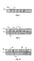
- FIG. 3is a schematic cross-sectional representation of a carrier substrate having apertures formed therethrough in accordance with the method of the present invention
- FIG. 4is a schematic cross-sectional representation of the relative alignment and assembly of the carrier substrate of FIG. 3 with a semiconductor device;
- FIG. 4Ais a schematic cross-sectional representation of the relative alignment and assembly of the carrier substrate of FIG. 3 with a semiconductor device and a quantity of polymeric or adhesive material disposed between the carrier substrate and the semiconductor device;
- FIG. 4Bis a perspective view illustrating the assembly of a wafer including a plurality of semiconductor devices with a substrate wafer;
- FIG. 5is a schematic cross-sectional representation of the formation or disposal of an insulative layer over at least the back side of the carrier substrate;
- FIG. 6is a schematic cross-sectional representation of the disposal of conductive material within the apertures of the carrier substrate of FIG. 4 or FIG. 5 to form electrically conductive vias;
- FIG. 6Ais a schematic cross-sectional representation of the disposal of two layers of conductive material within the apertures of the carrier substrate of FIG. 4 or FIG. 5 to form electrically conductive vias;
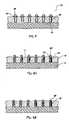
- FIG. 6Bis a schematic cross-sectional representation of the lining of the apertures of the carrier substrate of FIG. 4 or FIG. 5 with conductive material;
- FIG. 7is a schematic cross-sectional representation of the fabrication of contacts in communication with the electrically conductive vias of FIG. 6 ;
- FIG. 7Ais a schematic cross-sectional representation of the fabrication of laterally extending conductive traces and their corresponding contacts in communication with selected ones of the electrically conductive vias of FIG. 6 ;
- FIG. 8is a schematic cross-sectional representation of the disposal of conductive bumps adjacent the contacts of FIG. 7 ;
- FIGS. 8A and 8Bare schematic cross-sectional representations of the disposal of conductive bumps within the lined apertures of the carrier substrate of FIG. 6A ;
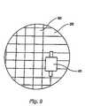
- FIG. 9is a schematic representation of the singulation of chip-scale packages from an assembled semiconductor device wafer and substrate wafer.
- Carrier substrate 10which is also referred to herein as a semiconductor substrate or simply as a carrier, is illustrated.
- Carrier substrate 10is a substantially planar structure that may be fabricated from a semiconductor material, such as silicon.
- An array of apertures 12is defined through carrier substrate 10 .
- apertures 12correspond substantially to the bond pads 16 (see FIG. 2A ) of a semiconductor device 14 to be assembled with carrier substrate 10 .
- carrier substrate 10may also include a quantity of conductive material 18 in each of apertures 12 .
- Each aperture 12which is coated with an insulative layer 13 , and the conductive material 18 therein collectively define an electrically conductive via 20 that extends substantially through carrier substrate 10 and through which signals may be communicated to or from a corresponding bond pad 16 .
- carrier substrate 10may also include conductive traces 22 extending laterally from vias 20 . As illustrated, conductive traces 22 are carried by carrier substrate 10 on or proximate a back side 11 thereof. Alternatively, conductive traces 22 may extend internally through carrier substrate 10 .
- Contacts 24may be disposed in communication with vias 20 and carried by carrier substrate 10 on or proximate back side 11 . If carrier substrate 10 includes any laterally extending conductive traces 22 , contacts 24 may be disposed adjacent such conductive traces 22 . Referring again to FIG. 2A , contacts 24 that communicate with vias 20 that do not include laterally extending conductive traces 22 may be disposed adjacent such vias 20 .
- a conductive bump 26such as a solder bump or a solder ball, may be disposed adjacent each contact 24 .
- Carrier substrate 10may also include insulative material 28 on back side 11 .
- Insulative material 28may be disposed in a layer that substantially covers back side 11 .
- the presence of insulative material 28 on back side 111is especially preferred if carrier substrate 10 includes any conductive traces 22 exposed at back side 11 .
- carrier substrate 10includes insulative material 28 , insulative layer 13 coating apertures 12 , vias 20 within apertures 12 , contacts 24 , or conductive bumps 26 are preferably exposed through insulative material 28 .
- FIGS. 2 and 2Aillustrate a chip-scale package 30 that includes a semiconductor device 14 invertedly oriented and disposed over carrier substrate 10 .
- semiconductor device 14is a flip-chip type semiconductor device that includes bond pads 16 disposed over an active surface 15 thereof in an array. Bond pads 16 of semiconductor device 14 align substantially with apertures 12 of carrier substrate 10 , thereby facilitating communication between each bond pad 16 and its corresponding via 20 .
- An intermediate layer 32may be disposed between semiconductor device 14 and carrier substrate 10 . If chip-scale package 30 includes such an intermediate layer 32 , bond pads 16 and their corresponding vias 20 are preferably exposed or otherwise communicate with one another through intermediate layer 32 .
- FIGS. 3-9a preferred embodiment of a method of fabricating chip-scale packages 30 in accordance with the method of the present invention is illustrated.
- the features of carrier substrate 10 and a chip-scale package 30 including carrier substrate 10are also described in greater detail with reference to FIGS. 3-9 .
- FIG. 3illustrates a carrier substrate 10 including an array of apertures 12 .
- Carrier substrate 10may be fabricated from a semiconductor material, such as silicon, gallium arsenide, silicon on glass (“SOG”), silicon on insulator (“SOI”), or silicon on sapphire (“SOS”).
- Carrier substrate 10may comprise a substantially chip-sized structure or may be part of a larger structure, such as a wafer (see FIG. 4B ).
- carrier substrate 10is fabricated from a silicon wafer.
- Each aperture 12which is lined with an insulative layer 13 , preferably extends substantially through carrier substrate 10 .
- the location of each aperture 12preferably corresponds substantially to a location of a bond pad 16 (see FIG. 4 ) of a semiconductor device 14 to be assembled with carrier substrate 10 .
- Apertures 12may be defined through carrier substrate 10 by known techniques, such as by known laser machining processes, which are also referred to herein as laser drilling techniques, or by known patterning processes (e.g., masking and etching).
- Insulative layer 13may be formed by known processes, such as by employing known oxidation techniques to oxidize the surfaces of apertures 12 .
- Apertures 12may be defined through carrier substrate 10 and lined with insulative layer 13 either before or after the assembly of carrier substrate 10 with semiconductor device 14 .
- carrier substrate 10may be disposed over semiconductor device 14 so as to substantially align each bond pad 16 thereof with its corresponding aperture 12 of carrier substrate 10 .
- Known processesmay be employed to align semiconductor device 14 and carrier substrate 10 .
- semiconductor device 14 and carrier substrate 10have substantially the same, or at least similar, coefficients of thermal expansion so as to maintain the integrity of a chip-scale package including semiconductor device 14 and carrier substrate 10 during the operation thereof.
- the thicknesses of carrier substrate 10 and semiconductor device 14are also preferably similar, and may be substantially the same. The thickness of semiconductor device 14 may, however, be greater than that of carrier substrate 10 since semiconductor device 14 includes integrated circuit devices that have been fabricated or built-up on active surface 15 thereof.
- an intermediate layer 32may be disposed between semiconductor device 14 and carrier substrate 10 .
- Intermediate layer 32may include a polymeric material or an adhesive material, such as a polyimide, that adheres semiconductor device 14 and carrier substrate 10 to one another.
- Intermediate layer 32may also insulate structures exposed at active surface 15 of semiconductor device 14 from carrier substrate 10 or structures thereof. Bond pads 16 are preferably exposed through intermediate layer 32 so as to facilitate the communication of signals to and from bond pads 16 through intermediate layer 32 and through vias 20 (see FIG. 2A ).
- Intermediate layer 32may be disposed on active surface 15 of semiconductor device 14 or on a surface of carrier substrate 10 by known processes, such as by spin-on techniques or other known processes that may be used to fabricate or form a layer with a substantially planar surface and having a substantially uniform thickness over the surface of a semiconductor device.
- carrier substrate 10 and semiconductor device 14may be assembled on a wafer scale.
- a wafer 34 including a plurality of semiconductor devices 14(see FIGS. 4 and 4A ), which is referred to herein as a semiconductor device wafer and may also be referred to as a second wafer, may be assembled with another wafer 36 , which is referred to herein as a substrate wafer and may also be referred to as a first wafer, from which the carrier substrate 10 of each chip-scale package 30 is defined.
- an insulative layer 38may be formed on back side 11 of carrier substrate 10 .
- Insulative layer 38may be formed by known processes, such as by growing a thermal oxide (e.g., a silicon oxide) layer on back side 11 and on any other exposed surfaces of carrier substrate 10 .
- a thermal oxidee.g., a silicon oxide
- an insulative layer 38 comprising thermal oxidemay be grown during a furnacing process, such as during a thermal anneal of conductive material 18 (see FIG. 6 ) to the portions of carrier substrate exposed in apertures 12 .
- a layer 38 of electrically insulative materialmay be deposited onto back side 11 and any other exposed surfaces of carrier substrate 10 by known techniques, such as chemical vapor deposition (“CVD”) processes.
- CVDchemical vapor deposition
- Insulative layer 38may be deposited, electrically insulative materials such as tetraethylorthosilicate (“TEOS”), silicon nitride, or glass (e.g., borophosphosilicate glass (“BPSG”), phosphosilicate glass (“PSG”), or borosilicate glass (“BSG”)) may be employed. Insulative layer 38 may be formed on carrier substrate 10 either prior to or after the assembly of carrier substrate 10 and semiconductor device 14 . The surfaces of carrier substrate 10 on which insulative layer 38 is present depends, at least in part, on the fabrication method and on whether or not carrier substrate 10 has been assembled with semiconductor device 14 .
- TEOStetraethylorthosilicate
- BPSGborophosphosilicate glass
- PSGphosphosilicate glass
- BSGborosilicate glass
- insulative layer 38may be removed from carrier substrate 10 .
- known processessuch as mask and etch techniques, may be employed. For example, it may be desirable to remove insulative layer 38 from the surfaces of apertures 12 from bond pads 16 , or from electrically conductive vias 20 .
- a mask including openings or apertures therethrough to expose apertures 12would be fabricated and employed in combination with an etchant that selectively etches the material of insulative layer over the material of bond pads 16 or the semiconductor material of carrier substrate 10 .
- Apertures 12are lined with a layer 13 of insulative material and substantially filled with conductive material 18 .
- Insulative layer 13may be formed by known processes, such as by oxidizing surfaces of apertures 12 .
- Conductive material 18may be disposed in apertures 12 by known processes, such as by known physical vapor deposition (“PVD”) processes (e.g., sputtering) or by chemical vapor deposition (“CVD”) processes. Any excess conductive material 18 may be removed from back side 11 by known processes, such as by known etching techniques or by known planarization processes (e.g., chemical-mechanical planarization (“CMP”)).
- PVDphysical vapor deposition
- CVDchemical vapor deposition
- conductive material 18contacts bond pads 16 of semiconductor device 14 .
- conductive material 18may diffuse, thereby forming a diffusion region or contact between conductive material 18 and the corresponding bond pad 16 , the disposal of conductive material 18 within apertures 12 may at least partially secure carrier substrate 10 and semiconductor device 14 to one another.
- conductive material 18in two layers 18 a and 18 b , a first layer 18 a of which includes a barrier-type material that reduces contact resistance and that may reduce or prevent diffusion between the semiconductor material of carrier substrate 10 and the conductive material of the second layer 18 b , which may cause electrical shorts between adjacent vias 20 or increase the resistance of a via 20 .
- Barrier materialsthat are known in the art, such as metal silicides, and that are compatible with both the semiconductor material of carrier substrate 10 and the conductive material of second layer 18 b may be employed. Such materials are particularly useful to prevent conductive material from spiking into the adjacent semiconductor material and, thereby, potentially causing electrical shorts between adjacent vias 20 .
- the barrier material of first layer 18 amay comprise titanium silicide.
- Such materialsmay be deposited by known processes, such as chemical vapor deposition or physical vapor deposition.
- selective depositioni.e., self-aligned silicide or “salicide” processes are employed, wherein the barrier material is disposed only on exposed regions of the semiconductor material, and not on an oxide coating thereover.
- the conductive material of layer 18 bmay then be deposited over the layer 18 a of barrier material by known processes, such as chemical vapor deposition or physical vapor deposition.
- Conductive material 18may be annealed to insulative layer 13 by known processes, such as by thermal anneal techniques.
- Any undesired regions of conductive material 18may be removed by known processes.
- known planarization techniquessuch as chemical-mechanical planarization or chemical-mechanical polishing, may be employed to substantially completely remove the conductive material 18 from back side 11 .
- known patterning processessuch as mask and etch techniques, may be employed to pattern conductive material 18 .
- conductive traces 22may be fabricated to reconfigure the footprint of contacts 24 on back side 11 relative to the footprint of bond pads 16 on active surface 15 of semiconductor device 14 .
- conductive traces 22preferably extend substantially laterally from their corresponding vias 20 and may be carried substantially internally by carrier substrate 10 or exposed at the back side 11 thereof.
- Conductive traces 22may be fabricated by known processes, such as by depositing one or more layers of conductive material onto a surface of carrier substrate 10 and patterning the layer or layers of conductive material. Alternatively, conductive traces 22 may be defined from layers 18 a and/or 18 b during patterning of these layers.
- contacts 24which communicate with bond pads 16 by means of vias 20 , may be carried by back side 11 of carrier substrate 10 .
- Contacts 24are preferably fabricated by known processes (e.g., fabricating the layers by PVD and patterning the layers by mask and etch processes), such as those employed to fabricate under-bump metallurgy (“UBM”) or ball-limiting metallurgy (“BLM”) structures.
- each contact 24may include an adhesion layer adjacent the conductive material 18 of its corresponding via 20 , a solder wetting layer adjacent the adhesion layer, and an exposed, substantially nonoxidizable protective layer (e.g., gold or other noble metal) adjacent the solder wetting layer.
- contacts 24may be patterned from the conductive material 18 disposed over back side 11 of carrier substrate 10 .
- Known processessuch as masking and etching, may be employed to define contacts 24 from conductive material 18 .
- conductive bumps 26may be disposed adjacent selected contacts 24 .
- An exemplary conductive bump 26 material that may be employed with the chip-scale package 30 of the present inventionis solder.
- the material of a conductive bump 26preferably bonds or adheres to an adjacent contact 24 and, thereby, facilitates electrical communication between conductive bump 26 and contact 24 .
- conductive bumps 26may be disposed directly adjacent to conductive material 18 of vias 20 .
- conductive materialmay be disposed in apertures 12 in one or more relatively thin layers 18 ′, such that hollow or open regions 19 ′ remain in at least some of apertures 12 .
- the conductive material of layer 18 ′is wettable by a conductive bump material, such as molten solder.
- a layer of barrier-type materialmay be disposed between layer 18 ′ and the adjacent surface of carrier substrate 10 to adhere the conductive material to carrier substrate 10 and to prevent diffusion of the semiconductor material of carrier substrate 10 with layer 18 ′.
- layer 18 ′includes a barrier material
- the barrier materialmay be disposed on the insulative layer 13 -lined surfaces of apertures 12 by known processes, such as by chemical vapor deposition or physical vapor deposition.
- the wettable conductive material of layer 18 ′may also be disposed over the insulative layer 13 -lined surface of each aperture 12 by known processes, such as chemical vapor deposition or physical vapor deposition.
- Barrier material or conductive materialmay be removed from back side 11 of carrier substrate 10 by known processes, such as by known patterning or planarization techniques.
- a conductive bump 28 ′ materialsuch as solder, may be disposed adjacent conductive layer 18 ′. If layer 18 ′ includes a material that is wettable by the conductive bump 28 ′ material employed, the conductive bump may be drawn into hollow region 19 ′ by capillary action, or “wicking.”
- chip-scale packages 30 of the present inventionmay be fabricated on a wafer scale, as depicted in FIG. 4B , testing, probing, or burn-in of each of the semiconductor devices 14 of semiconductor device wafer 34 can be performed after packaging, but while the semiconductor devices are still in wafer form.
- the packaging method of the present inventioneliminates the need to individually align individually packaged semiconductor devices with test equipment.
- individual chip-scale packages 30may be singulate from the assembly of semiconductor device wafer 34 (not shown) and substrate wafer 36 by known singulation processes, such as by the use of a wafer saw 40 .
Landscapes
- Engineering & Computer Science (AREA)
- Computer Hardware Design (AREA)
- Microelectronics & Electronic Packaging (AREA)
- Power Engineering (AREA)
- Physics & Mathematics (AREA)
- Condensed Matter Physics & Semiconductors (AREA)
- General Physics & Mathematics (AREA)
- Manufacturing & Machinery (AREA)
- Internal Circuitry In Semiconductor Integrated Circuit Devices (AREA)
- Wire Bonding (AREA)
Abstract
Description
Claims (53)
Priority Applications (2)
| Application Number | Priority Date | Filing Date | Title |
|---|---|---|---|
| US09/652,495US7271491B1 (en) | 2000-08-31 | 2000-08-31 | Carrier for wafer-scale package and wafer-scale package including the carrier |
| US10/200,793US7517797B2 (en) | 2000-08-31 | 2002-07-22 | Carrier for wafer-scale package, wafer-scale package including the carrier, and methods |
Applications Claiming Priority (1)
| Application Number | Priority Date | Filing Date | Title |
|---|---|---|---|
| US09/652,495US7271491B1 (en) | 2000-08-31 | 2000-08-31 | Carrier for wafer-scale package and wafer-scale package including the carrier |
Related Child Applications (1)
| Application Number | Title | Priority Date | Filing Date |
|---|---|---|---|
| US10/200,793DivisionUS7517797B2 (en) | 2000-08-31 | 2002-07-22 | Carrier for wafer-scale package, wafer-scale package including the carrier, and methods |
Publications (1)
| Publication Number | Publication Date |
|---|---|
| US7271491B1true US7271491B1 (en) | 2007-09-18 |
Family
ID=24617025
Family Applications (2)
| Application Number | Title | Priority Date | Filing Date |
|---|---|---|---|
| US09/652,495Expired - LifetimeUS7271491B1 (en) | 2000-08-31 | 2000-08-31 | Carrier for wafer-scale package and wafer-scale package including the carrier |
| US10/200,793Expired - LifetimeUS7517797B2 (en) | 2000-08-31 | 2002-07-22 | Carrier for wafer-scale package, wafer-scale package including the carrier, and methods |
Family Applications After (1)
| Application Number | Title | Priority Date | Filing Date |
|---|---|---|---|
| US10/200,793Expired - LifetimeUS7517797B2 (en) | 2000-08-31 | 2002-07-22 | Carrier for wafer-scale package, wafer-scale package including the carrier, and methods |
Country Status (1)
| Country | Link |
|---|---|
| US (2) | US7271491B1 (en) |
Cited By (25)
| Publication number | Priority date | Publication date | Assignee | Title |
|---|---|---|---|---|
| US20070284602A1 (en)* | 2004-06-30 | 2007-12-13 | Ashay Chitnis | Dielectric wafer level bonding with conductive feed-throughs for electrical connection and thermal management |
| US20080096365A1 (en)* | 2006-10-20 | 2008-04-24 | Cree, Inc. | Permanent wafer bonding using metal alloy preform discs |
| US7482272B2 (en) | 2005-06-14 | 2009-01-27 | John Trezza | Through chip connection |
| US20090072391A1 (en)* | 2004-05-06 | 2009-03-19 | Ravi Kanth Kolan | Structurally-enhanced integrated circuit package and method of manufacture |
| US7521806B2 (en) | 2005-06-14 | 2009-04-21 | John Trezza | Chip spanning connection |
| US7534722B2 (en) | 2005-06-14 | 2009-05-19 | John Trezza | Back-to-front via process |
| US7560813B2 (en) | 2005-06-14 | 2009-07-14 | John Trezza | Chip-based thermo-stack |
| US7659202B2 (en) | 2005-06-14 | 2010-02-09 | John Trezza | Triaxial through-chip connection |
| US20100032808A1 (en)* | 2008-08-08 | 2010-02-11 | Hanyi Ding | Through wafer via and method of making same |
| US20100032764A1 (en)* | 2008-08-08 | 2010-02-11 | Paul Stephen Andry | Through silicon via and method of fabricating same |
| US20100035430A1 (en)* | 2008-08-08 | 2010-02-11 | Paul Stephen Andry | Method of making through wafer vias |
| US20100032811A1 (en)* | 2008-08-08 | 2010-02-11 | Hanyi Ding | Through wafer vias and method of making same |
| US20100032810A1 (en)* | 2008-08-08 | 2010-02-11 | Hanyi Ding | Through wafer vias and method of making same |
| US7670874B2 (en) | 2007-02-16 | 2010-03-02 | John Trezza | Plated pillar package formation |
| US7687400B2 (en) | 2005-06-14 | 2010-03-30 | John Trezza | Side stacking apparatus and method |
| US7687397B2 (en) | 2006-06-06 | 2010-03-30 | John Trezza | Front-end processed wafer having through-chip connections |
| US7781886B2 (en) | 2005-06-14 | 2010-08-24 | John Trezza | Electronic chip contact structure |
| US7786592B2 (en) | 2005-06-14 | 2010-08-31 | John Trezza | Chip capacitive coupling |
| US20100270685A1 (en)* | 2009-04-03 | 2010-10-28 | Research Triangle Institute | Die bonding utilizing a patterned adhesion layer |
| US7838997B2 (en) | 2005-06-14 | 2010-11-23 | John Trezza | Remote chip attachment |
| US7851348B2 (en) | 2005-06-14 | 2010-12-14 | Abhay Misra | Routingless chip architecture |
| US20110217814A1 (en)* | 2008-10-23 | 2011-09-08 | Freescale Semiconductor, Inc. | Method for singulating electronic components from a substrate |
| US8456015B2 (en) | 2005-06-14 | 2013-06-04 | Cufer Asset Ltd. L.L.C. | Triaxial through-chip connection |
| US9576889B2 (en) | 2012-06-25 | 2017-02-21 | Research Triangle Institute | Three-dimensional electronic packages utilizing unpatterned adhesive layer |
| US9881905B2 (en) | 2014-04-21 | 2018-01-30 | Research Triangle Institute | Electronic packages with three-dimensional conductive planes, and methods for fabrication |
Families Citing this family (6)
| Publication number | Priority date | Publication date | Assignee | Title |
|---|---|---|---|---|
| US6819001B2 (en)* | 2003-03-14 | 2004-11-16 | General Electric Company | Interposer, interposer package and device assembly employing the same |
| US7173231B2 (en)* | 2003-09-16 | 2007-02-06 | Wen Ching Chen | Chip scale package structure for an image sensor |
| JP4351214B2 (en)* | 2003-11-07 | 2009-10-28 | 新光電気工業株式会社 | Electronic device and manufacturing method thereof |
| US8288872B2 (en)* | 2008-08-05 | 2012-10-16 | Taiwan Semiconductor Manufacturing Company, Ltd. | Through silicon via layout |
| NL2009757C2 (en) | 2012-11-05 | 2014-05-08 | Micronit Microfluidics Bv | Method for forming an electrically conductive via in a substrate. |
| US9368458B2 (en)* | 2013-07-10 | 2016-06-14 | Taiwan Semiconductor Manufacturing Company, Ltd. | Die-on-interposer assembly with dam structure and method of manufacturing the same |
Citations (31)
| Publication number | Priority date | Publication date | Assignee | Title |
|---|---|---|---|---|
| JPS63157430A (en) | 1986-12-22 | 1988-06-30 | Matsushita Electronics Corp | Die bonding method for semiconductor device |
| US5185295A (en) | 1990-05-16 | 1993-02-09 | Kabushiki Kaisha Toshiba | Method for dicing semiconductor substrates using a laser scribing and dual etch process |
| US5229647A (en)* | 1991-03-27 | 1993-07-20 | Micron Technology, Inc. | High density data storage using stacked wafers |
| US5258648A (en)* | 1991-06-27 | 1993-11-02 | Motorola, Inc. | Composite flip chip semiconductor device with an interposer having test contacts formed along its periphery |
| US5291438A (en) | 1992-03-23 | 1994-03-01 | Motorola, Inc. | Transistor and a capacitor used for forming a vertically stacked dynamic random access memory cell |
| US5418687A (en) | 1994-02-01 | 1995-05-23 | Hewlett-Packard Company | Wafer scale multi-chip module |
| US5440241A (en) | 1992-03-06 | 1995-08-08 | Micron Technology, Inc. | Method for testing, burning-in, and manufacturing wafer scale integrated circuits and a packaged wafer assembly produced thereby |
| US5682062A (en)* | 1995-06-05 | 1997-10-28 | Harris Corporation | System for interconnecting stacked integrated circuits |
| US5685885A (en) | 1990-09-24 | 1997-11-11 | Tessera, Inc. | Wafer-scale techniques for fabrication of semiconductor chip assemblies |
| US5742100A (en) | 1995-03-27 | 1998-04-21 | Motorola, Inc. | Structure having flip-chip connected substrates |
| US5767575A (en) | 1995-10-17 | 1998-06-16 | Prolinx Labs Corporation | Ball grid array structure and method for packaging an integrated circuit chip |
| US5870289A (en)* | 1994-12-15 | 1999-02-09 | Hitachi, Ltd. | Chip connection structure having diret through-hole connections through adhesive film and wiring substrate |
| US5892288A (en)* | 1997-05-30 | 1999-04-06 | Mitsubishi Denki Kabushiki Kaisha | Semiconductor integrated circuit device |
| US5940679A (en) | 1995-01-06 | 1999-08-17 | Matsushita Electric Industrial Co., Ltd. | Method of checking electric circuits of semiconductor device and conductive adhesive for checking usage |
| US5946555A (en) | 1996-11-04 | 1999-08-31 | Packard Hughes Interconnect Company | Wafer level decal for minimal packaging of chips |
| US5949140A (en) | 1996-05-30 | 1999-09-07 | Oki Electric Industry Co., Ltd. | Microwave semiconductor device with via holes and associated structure |
| US5973396A (en)* | 1996-02-16 | 1999-10-26 | Micron Technology, Inc. | Surface mount IC using silicon vias in an area array format or same size as die array |
| US5990546A (en)* | 1994-12-29 | 1999-11-23 | Nitto Denko Corporation | Chip scale package type of semiconductor device |
| US6004867A (en)* | 1996-12-16 | 1999-12-21 | Samsung Electronics Co., Ltd. | Chip-size packages assembled using mass production techniques at the wafer-level |
| US6037665A (en) | 1997-03-03 | 2000-03-14 | Nec Corporation | Mounting assembly of integrated circuit device and method for production thereof |
| US6064114A (en) | 1997-12-01 | 2000-05-16 | Motorola, Inc. | Semiconductor device having a sub-chip-scale package structure and method for forming same |
| US6114187A (en) | 1997-01-11 | 2000-09-05 | Microfab Technologies, Inc. | Method for preparing a chip scale package and product produced by the method |
| US6197613B1 (en) | 1999-03-23 | 2001-03-06 | Industrial Technology Research Institute | Wafer level packaging method and devices formed |
| US6228687B1 (en) | 1999-06-28 | 2001-05-08 | Micron Technology, Inc. | Wafer-level package and methods of fabricating |
| US6291272B1 (en) | 1999-12-23 | 2001-09-18 | International Business Machines Corporation | Structure and process for making substrate packages for high frequency application |
| US6297553B1 (en)* | 1998-10-30 | 2001-10-02 | Shinko Electric Industries Co., Ltd | Semiconductor device and process for producing the same |
| US6392296B1 (en) | 1998-08-31 | 2002-05-21 | Micron Technology, Inc. | Silicon interposer with optical connections |
| US6440771B1 (en) | 2001-03-23 | 2002-08-27 | Eaglestone Partners I, Llc | Method for constructing a wafer interposer by using conductive columns |
| US6458623B1 (en) | 2001-01-17 | 2002-10-01 | International Business Machines Corporation | Conductive adhesive interconnection with insulating polymer carrier |
| US6809421B1 (en) | 1996-12-02 | 2004-10-26 | Kabushiki Kaisha Toshiba | Multichip semiconductor device, chip therefor and method of formation thereof |
| US6955870B2 (en) | 2001-10-17 | 2005-10-18 | Hitachi, Ltd. | Method of manufacturing a semiconductor device |
Family Cites Families (3)
| Publication number | Priority date | Publication date | Assignee | Title |
|---|---|---|---|---|
| DE3684602D1 (en)* | 1986-10-08 | 1992-04-30 | Ibm | METHOD FOR PRODUCING SOLDER CONTACTS FOR A CERAMIC MODULE WITHOUT PLUGS. |
| US6294407B1 (en) | 1998-05-06 | 2001-09-25 | Virtual Integration, Inc. | Microelectronic packages including thin film decal and dielectric adhesive layer having conductive vias therein, and methods of fabricating the same |
| US6455354B1 (en)* | 1998-12-30 | 2002-09-24 | Micron Technology, Inc. | Method of fabricating tape attachment chip-on-board assemblies |
- 2000
- 2000-08-31USUS09/652,495patent/US7271491B1/ennot_activeExpired - Lifetime
- 2002
- 2002-07-22USUS10/200,793patent/US7517797B2/ennot_activeExpired - Lifetime
Patent Citations (33)
| Publication number | Priority date | Publication date | Assignee | Title |
|---|---|---|---|---|
| JPS63157430A (en) | 1986-12-22 | 1988-06-30 | Matsushita Electronics Corp | Die bonding method for semiconductor device |
| US5185295A (en) | 1990-05-16 | 1993-02-09 | Kabushiki Kaisha Toshiba | Method for dicing semiconductor substrates using a laser scribing and dual etch process |
| US5685885A (en) | 1990-09-24 | 1997-11-11 | Tessera, Inc. | Wafer-scale techniques for fabrication of semiconductor chip assemblies |
| US5229647A (en)* | 1991-03-27 | 1993-07-20 | Micron Technology, Inc. | High density data storage using stacked wafers |
| US5258648A (en)* | 1991-06-27 | 1993-11-02 | Motorola, Inc. | Composite flip chip semiconductor device with an interposer having test contacts formed along its periphery |
| US5440241A (en) | 1992-03-06 | 1995-08-08 | Micron Technology, Inc. | Method for testing, burning-in, and manufacturing wafer scale integrated circuits and a packaged wafer assembly produced thereby |
| US5291438A (en) | 1992-03-23 | 1994-03-01 | Motorola, Inc. | Transistor and a capacitor used for forming a vertically stacked dynamic random access memory cell |
| US5418687A (en) | 1994-02-01 | 1995-05-23 | Hewlett-Packard Company | Wafer scale multi-chip module |
| US5506383A (en) | 1994-02-01 | 1996-04-09 | Hewlett-Packard Company | Wafer scale multi-chip module |
| US5870289A (en)* | 1994-12-15 | 1999-02-09 | Hitachi, Ltd. | Chip connection structure having diret through-hole connections through adhesive film and wiring substrate |
| US5990546A (en)* | 1994-12-29 | 1999-11-23 | Nitto Denko Corporation | Chip scale package type of semiconductor device |
| US5940679A (en) | 1995-01-06 | 1999-08-17 | Matsushita Electric Industrial Co., Ltd. | Method of checking electric circuits of semiconductor device and conductive adhesive for checking usage |
| US5742100A (en) | 1995-03-27 | 1998-04-21 | Motorola, Inc. | Structure having flip-chip connected substrates |
| US5682062A (en)* | 1995-06-05 | 1997-10-28 | Harris Corporation | System for interconnecting stacked integrated circuits |
| US5767575A (en) | 1995-10-17 | 1998-06-16 | Prolinx Labs Corporation | Ball grid array structure and method for packaging an integrated circuit chip |
| US5973396A (en)* | 1996-02-16 | 1999-10-26 | Micron Technology, Inc. | Surface mount IC using silicon vias in an area array format or same size as die array |
| US5949140A (en) | 1996-05-30 | 1999-09-07 | Oki Electric Industry Co., Ltd. | Microwave semiconductor device with via holes and associated structure |
| US5946555A (en) | 1996-11-04 | 1999-08-31 | Packard Hughes Interconnect Company | Wafer level decal for minimal packaging of chips |
| US6809421B1 (en) | 1996-12-02 | 2004-10-26 | Kabushiki Kaisha Toshiba | Multichip semiconductor device, chip therefor and method of formation thereof |
| US6004867A (en)* | 1996-12-16 | 1999-12-21 | Samsung Electronics Co., Ltd. | Chip-size packages assembled using mass production techniques at the wafer-level |
| US6114187A (en) | 1997-01-11 | 2000-09-05 | Microfab Technologies, Inc. | Method for preparing a chip scale package and product produced by the method |
| US6037665A (en) | 1997-03-03 | 2000-03-14 | Nec Corporation | Mounting assembly of integrated circuit device and method for production thereof |
| US5892288A (en)* | 1997-05-30 | 1999-04-06 | Mitsubishi Denki Kabushiki Kaisha | Semiconductor integrated circuit device |
| US6064114A (en) | 1997-12-01 | 2000-05-16 | Motorola, Inc. | Semiconductor device having a sub-chip-scale package structure and method for forming same |
| US6294405B1 (en)* | 1997-12-01 | 2001-09-25 | Motorola Inc. | Method of forming semiconductor device having a sub-chip-scale package structure |
| US6392296B1 (en) | 1998-08-31 | 2002-05-21 | Micron Technology, Inc. | Silicon interposer with optical connections |
| US6297553B1 (en)* | 1998-10-30 | 2001-10-02 | Shinko Electric Industries Co., Ltd | Semiconductor device and process for producing the same |
| US6197613B1 (en) | 1999-03-23 | 2001-03-06 | Industrial Technology Research Institute | Wafer level packaging method and devices formed |
| US6228687B1 (en) | 1999-06-28 | 2001-05-08 | Micron Technology, Inc. | Wafer-level package and methods of fabricating |
| US6291272B1 (en) | 1999-12-23 | 2001-09-18 | International Business Machines Corporation | Structure and process for making substrate packages for high frequency application |
| US6458623B1 (en) | 2001-01-17 | 2002-10-01 | International Business Machines Corporation | Conductive adhesive interconnection with insulating polymer carrier |
| US6440771B1 (en) | 2001-03-23 | 2002-08-27 | Eaglestone Partners I, Llc | Method for constructing a wafer interposer by using conductive columns |
| US6955870B2 (en) | 2001-10-17 | 2005-10-18 | Hitachi, Ltd. | Method of manufacturing a semiconductor device |
Cited By (67)
| Publication number | Priority date | Publication date | Assignee | Title |
|---|---|---|---|---|
| US7830006B2 (en)* | 2004-05-06 | 2010-11-09 | United Test And Assembly Center, Ltd. | Structurally-enhanced integrated circuit package and method of manufacture |
| US20090072391A1 (en)* | 2004-05-06 | 2009-03-19 | Ravi Kanth Kolan | Structurally-enhanced integrated circuit package and method of manufacture |
| US9368428B2 (en)* | 2004-06-30 | 2016-06-14 | Cree, Inc. | Dielectric wafer level bonding with conductive feed-throughs for electrical connection and thermal management |
| US20070284602A1 (en)* | 2004-06-30 | 2007-12-13 | Ashay Chitnis | Dielectric wafer level bonding with conductive feed-throughs for electrical connection and thermal management |
| US8283778B2 (en) | 2005-06-14 | 2012-10-09 | Cufer Asset Ltd. L.L.C. | Thermally balanced via |
| US7781886B2 (en) | 2005-06-14 | 2010-08-24 | John Trezza | Electronic chip contact structure |
| US7538033B2 (en)* | 2005-06-14 | 2009-05-26 | John Trezza | Post-attachment chip-to-chip connection |
| US7560813B2 (en) | 2005-06-14 | 2009-07-14 | John Trezza | Chip-based thermo-stack |
| US7659202B2 (en) | 2005-06-14 | 2010-02-09 | John Trezza | Triaxial through-chip connection |
| US9324629B2 (en) | 2005-06-14 | 2016-04-26 | Cufer Asset Ltd. L.L.C. | Tooling for coupling multiple electronic chips |
| US9147635B2 (en) | 2005-06-14 | 2015-09-29 | Cufer Asset Ltd. L.L.C. | Contact-based encapsulation |
| US8846445B2 (en) | 2005-06-14 | 2014-09-30 | Cufer Asset Ltd. L.L.C. | Inverse chip connector |
| US8643186B2 (en) | 2005-06-14 | 2014-02-04 | Cufer Asset Ltd. L.L.C. | Processed wafer via |
| US8456015B2 (en) | 2005-06-14 | 2013-06-04 | Cufer Asset Ltd. L.L.C. | Triaxial through-chip connection |
| US7482272B2 (en) | 2005-06-14 | 2009-01-27 | John Trezza | Through chip connection |
| US8232194B2 (en) | 2005-06-14 | 2012-07-31 | Cufer Asset Ltd. L.L.C. | Process for chip capacitive coupling |
| US7687400B2 (en) | 2005-06-14 | 2010-03-30 | John Trezza | Side stacking apparatus and method |
| US8197627B2 (en) | 2005-06-14 | 2012-06-12 | Cufer Asset Ltd. L.L.C. | Pin-type chip tooling |
| US7767493B2 (en) | 2005-06-14 | 2010-08-03 | John Trezza | Post & penetration interconnection |
| US8197626B2 (en) | 2005-06-14 | 2012-06-12 | Cufer Asset Ltd. L.L.C. | Rigid-backed, membrane-based chip tooling |
| US7785987B2 (en) | 2005-06-14 | 2010-08-31 | John Trezza | Isolating chip-to-chip contact |
| US7786592B2 (en) | 2005-06-14 | 2010-08-31 | John Trezza | Chip capacitive coupling |
| US7785931B2 (en) | 2005-06-14 | 2010-08-31 | John Trezza | Chip-based thermo-stack |
| US7808111B2 (en) | 2005-06-14 | 2010-10-05 | John Trezza | Processed wafer via |
| US8154131B2 (en) | 2005-06-14 | 2012-04-10 | Cufer Asset Ltd. L.L.C. | Profiled contact |
| US7521806B2 (en) | 2005-06-14 | 2009-04-21 | John Trezza | Chip spanning connection |
| US7838997B2 (en) | 2005-06-14 | 2010-11-23 | John Trezza | Remote chip attachment |
| US7847412B2 (en) | 2005-06-14 | 2010-12-07 | John Trezza | Isolating chip-to-chip contact |
| US7851348B2 (en) | 2005-06-14 | 2010-12-14 | Abhay Misra | Routingless chip architecture |
| US7884483B2 (en) | 2005-06-14 | 2011-02-08 | Cufer Asset Ltd. L.L.C. | Chip connector |
| US7919870B2 (en) | 2005-06-14 | 2011-04-05 | Cufer Asset Ltd. L.L.C. | Coaxial through chip connection |
| US7932584B2 (en) | 2005-06-14 | 2011-04-26 | Cufer Asset Ltd. L.L.C. | Stacked chip-based system and method |
| US7942182B2 (en) | 2005-06-14 | 2011-05-17 | Cufer Asset Ltd. L.L.C. | Rigid-backed, membrane-based chip tooling |
| US7946331B2 (en) | 2005-06-14 | 2011-05-24 | Cufer Asset Ltd. L.L.C. | Pin-type chip tooling |
| US7534722B2 (en) | 2005-06-14 | 2009-05-19 | John Trezza | Back-to-front via process |
| US8093729B2 (en) | 2005-06-14 | 2012-01-10 | Cufer Asset Ltd. L.L.C. | Electrically conductive interconnect system and method |
| US7969015B2 (en) | 2005-06-14 | 2011-06-28 | Cufer Asset Ltd. L.L.C. | Inverse chip connector |
| US8021922B2 (en) | 2005-06-14 | 2011-09-20 | Cufer Asset Ltd. L.L.C. | Remote chip attachment |
| US7989958B2 (en) | 2005-06-14 | 2011-08-02 | Cufer Assett Ltd. L.L.C. | Patterned contact |
| US8053903B2 (en) | 2005-06-14 | 2011-11-08 | Cufer Asset Ltd. L.L.C. | Chip capacitive coupling |
| US8067312B2 (en) | 2005-06-14 | 2011-11-29 | Cufer Asset Ltd. L.L.C. | Coaxial through chip connection |
| US8084851B2 (en) | 2005-06-14 | 2011-12-27 | Cufer Asset Ltd. L.L.C. | Side stacking apparatus and method |
| US7687397B2 (en) | 2006-06-06 | 2010-03-30 | John Trezza | Front-end processed wafer having through-chip connections |
| US10873002B2 (en) | 2006-10-20 | 2020-12-22 | Cree, Inc. | Permanent wafer bonding using metal alloy preform discs |
| US20080096365A1 (en)* | 2006-10-20 | 2008-04-24 | Cree, Inc. | Permanent wafer bonding using metal alloy preform discs |
| US7670874B2 (en) | 2007-02-16 | 2010-03-02 | John Trezza | Plated pillar package formation |
| US20100032764A1 (en)* | 2008-08-08 | 2010-02-11 | Paul Stephen Andry | Through silicon via and method of fabricating same |
| US8748308B2 (en) | 2008-08-08 | 2014-06-10 | International Business Machines Corporation | Through wafer vias and method of making same |
| US8138036B2 (en) | 2008-08-08 | 2012-03-20 | International Business Machines Corporation | Through silicon via and method of fabricating same |
| US8299566B2 (en) | 2008-08-08 | 2012-10-30 | International Business Machines Corporation | Through wafer vias and method of making same |
| US8637937B2 (en) | 2008-08-08 | 2014-01-28 | Ultratech, Inc. | Through silicon via for use in integrated circuit chips |
| US8384224B2 (en) | 2008-08-08 | 2013-02-26 | International Business Machines Corporation | Through wafer vias and method of making same |
| US20100032810A1 (en)* | 2008-08-08 | 2010-02-11 | Hanyi Ding | Through wafer vias and method of making same |
| US8035198B2 (en) | 2008-08-08 | 2011-10-11 | International Business Machines Corporation | Through wafer via and method of making same |
| US20100032808A1 (en)* | 2008-08-08 | 2010-02-11 | Hanyi Ding | Through wafer via and method of making same |
| US8518787B2 (en) | 2008-08-08 | 2013-08-27 | International Business Machines Corporation | Through wafer vias and method of making same |
| US8735251B2 (en) | 2008-08-08 | 2014-05-27 | Ultratech, Inc. | Through silicon via and method of fabricating same |
| US7678696B2 (en) | 2008-08-08 | 2010-03-16 | International Business Machines Corporation | Method of making through wafer vias |
| US20100035430A1 (en)* | 2008-08-08 | 2010-02-11 | Paul Stephen Andry | Method of making through wafer vias |
| US20100032811A1 (en)* | 2008-08-08 | 2010-02-11 | Hanyi Ding | Through wafer vias and method of making same |
| US9142434B2 (en) | 2008-10-23 | 2015-09-22 | Freescale Semiconductor, Inc. | Method for singulating electronic components from a substrate |
| US20110217814A1 (en)* | 2008-10-23 | 2011-09-08 | Freescale Semiconductor, Inc. | Method for singulating electronic components from a substrate |
| US20100270685A1 (en)* | 2009-04-03 | 2010-10-28 | Research Triangle Institute | Die bonding utilizing a patterned adhesion layer |
| US8361901B2 (en)* | 2009-04-03 | 2013-01-29 | Research Triangle Institute | Die bonding utilizing a patterned adhesion layer |
| US9576889B2 (en) | 2012-06-25 | 2017-02-21 | Research Triangle Institute | Three-dimensional electronic packages utilizing unpatterned adhesive layer |
| US9881905B2 (en) | 2014-04-21 | 2018-01-30 | Research Triangle Institute | Electronic packages with three-dimensional conductive planes, and methods for fabrication |
| US10418344B2 (en) | 2014-04-21 | 2019-09-17 | Micross Advanced Interconnect Technology Llc | Electronic packages with three-dimensional conductive planes, and methods for fabrication |
Also Published As
| Publication number | Publication date |
|---|---|
| US20020182771A1 (en) | 2002-12-05 |
| US7517797B2 (en) | 2009-04-14 |
Similar Documents
| Publication | Publication Date | Title |
|---|---|---|
| US7271491B1 (en) | Carrier for wafer-scale package and wafer-scale package including the carrier | |
| US7368812B2 (en) | Interposers for chip-scale packages and intermediates thereof | |
| US6333559B1 (en) | Method/structure for creating aluminum wirebound pad on copper BEOL | |
| US6265300B1 (en) | Wire bonding surface and bonding method | |
| US6727590B2 (en) | Semiconductor device with internal bonding pad | |
| US7498675B2 (en) | Semiconductor component having plate, stacked dice and conductive vias | |
| EP1842233B1 (en) | Method of forming bump sites on bond-pads | |
| TWI479601B (en) | Method for forming a conductive viathrough a semiconductor device structure,method for fabricating a semiconductor device structure,semiconductor device structure,and electronic device | |
| US20030020163A1 (en) | Bonding pad structure for copper/low-k dielectric material BEOL process | |
| US20060019467A1 (en) | Methods of fabricating integrated circuit chips for multi-chip packaging and wafers and chips formed thereby | |
| CN110444482A (en) | Semiconductor structure and method for forming semiconductor structure | |
| US20060166402A1 (en) | Elevated bond-pad structure for high-density flip-clip packaging and a method of fabricating the structures | |
| US9607957B2 (en) | Semiconductor device | |
| KR20080050332A (en) | Semiconductor device and manufacturing method of semiconductor device | |
| JP2012507163A (en) | Semiconductor device including reduced stress structure for metal pillars | |
| US12205853B2 (en) | Integrated circuit test method and structure thereof | |
| US7009300B2 (en) | Low profile stacked multi-chip package and method of forming same | |
| US20030178644A1 (en) | Reinforced bond-pad substructure and method for fabricating the same | |
| US7176117B2 (en) | Method for mounting passive components on wafer | |
| US7119002B2 (en) | Solder bump composition for flip chip | |
| US20030166334A1 (en) | Bond pad and process for fabricating the same | |
| WO2005062367A1 (en) | I/o sites for probe test and wire bond | |
| KR100277851B1 (en) | Pad of semiconductor device and method for forming the same |
Legal Events
| Date | Code | Title | Description |
|---|---|---|---|
| AS | Assignment | Owner name:MICRON TECHNOLOGY, INC., IDAHO Free format text:ASSIGNMENT OF ASSIGNORS INTEREST;ASSIGNOR:AKRAM, SALMAN;REEL/FRAME:011070/0823 Effective date:20000831 | |
| FEPP | Fee payment procedure | Free format text:PAYOR NUMBER ASSIGNED (ORIGINAL EVENT CODE: ASPN); ENTITY STATUS OF PATENT OWNER: LARGE ENTITY | |
| STCF | Information on status: patent grant | Free format text:PATENTED CASE | |
| FPAY | Fee payment | Year of fee payment:4 | |
| FPAY | Fee payment | Year of fee payment:8 | |
| AS | Assignment | Owner name:U.S. BANK NATIONAL ASSOCIATION, AS COLLATERAL AGENT, CALIFORNIA Free format text:SECURITY INTEREST;ASSIGNOR:MICRON TECHNOLOGY, INC.;REEL/FRAME:038669/0001 Effective date:20160426 Owner name:U.S. BANK NATIONAL ASSOCIATION, AS COLLATERAL AGEN Free format text:SECURITY INTEREST;ASSIGNOR:MICRON TECHNOLOGY, INC.;REEL/FRAME:038669/0001 Effective date:20160426 | |
| AS | Assignment | Owner name:MORGAN STANLEY SENIOR FUNDING, INC., AS COLLATERAL AGENT, MARYLAND Free format text:PATENT SECURITY AGREEMENT;ASSIGNOR:MICRON TECHNOLOGY, INC.;REEL/FRAME:038954/0001 Effective date:20160426 Owner name:MORGAN STANLEY SENIOR FUNDING, INC., AS COLLATERAL Free format text:PATENT SECURITY AGREEMENT;ASSIGNOR:MICRON TECHNOLOGY, INC.;REEL/FRAME:038954/0001 Effective date:20160426 | |
| AS | Assignment | Owner name:U.S. BANK NATIONAL ASSOCIATION, AS COLLATERAL AGENT, CALIFORNIA Free format text:CORRECTIVE ASSIGNMENT TO CORRECT THE REPLACE ERRONEOUSLY FILED PATENT #7358718 WITH THE CORRECT PATENT #7358178 PREVIOUSLY RECORDED ON REEL 038669 FRAME 0001. ASSIGNOR(S) HEREBY CONFIRMS THE SECURITY INTEREST;ASSIGNOR:MICRON TECHNOLOGY, INC.;REEL/FRAME:043079/0001 Effective date:20160426 Owner name:U.S. BANK NATIONAL ASSOCIATION, AS COLLATERAL AGEN Free format text:CORRECTIVE ASSIGNMENT TO CORRECT THE REPLACE ERRONEOUSLY FILED PATENT #7358718 WITH THE CORRECT PATENT #7358178 PREVIOUSLY RECORDED ON REEL 038669 FRAME 0001. ASSIGNOR(S) HEREBY CONFIRMS THE SECURITY INTEREST;ASSIGNOR:MICRON TECHNOLOGY, INC.;REEL/FRAME:043079/0001 Effective date:20160426 | |
| AS | Assignment | Owner name:JPMORGAN CHASE BANK, N.A., AS COLLATERAL AGENT, ILLINOIS Free format text:SECURITY INTEREST;ASSIGNORS:MICRON TECHNOLOGY, INC.;MICRON SEMICONDUCTOR PRODUCTS, INC.;REEL/FRAME:047540/0001 Effective date:20180703 Owner name:JPMORGAN CHASE BANK, N.A., AS COLLATERAL AGENT, IL Free format text:SECURITY INTEREST;ASSIGNORS:MICRON TECHNOLOGY, INC.;MICRON SEMICONDUCTOR PRODUCTS, INC.;REEL/FRAME:047540/0001 Effective date:20180703 | |
| AS | Assignment | Owner name:MICRON TECHNOLOGY, INC., IDAHO Free format text:RELEASE BY SECURED PARTY;ASSIGNOR:U.S. BANK NATIONAL ASSOCIATION, AS COLLATERAL AGENT;REEL/FRAME:047243/0001 Effective date:20180629 | |
| MAFP | Maintenance fee payment | Free format text:PAYMENT OF MAINTENANCE FEE, 12TH YEAR, LARGE ENTITY (ORIGINAL EVENT CODE: M1553); ENTITY STATUS OF PATENT OWNER: LARGE ENTITY Year of fee payment:12 | |
| AS | Assignment | Owner name:MICRON TECHNOLOGY, INC., IDAHO Free format text:RELEASE BY SECURED PARTY;ASSIGNOR:MORGAN STANLEY SENIOR FUNDING, INC., AS COLLATERAL AGENT;REEL/FRAME:050937/0001 Effective date:20190731 | |
| AS | Assignment | Owner name:MICRON TECHNOLOGY, INC., IDAHO Free format text:RELEASE BY SECURED PARTY;ASSIGNOR:JPMORGAN CHASE BANK, N.A., AS COLLATERAL AGENT;REEL/FRAME:051028/0001 Effective date:20190731 Owner name:MICRON SEMICONDUCTOR PRODUCTS, INC., IDAHO Free format text:RELEASE BY SECURED PARTY;ASSIGNOR:JPMORGAN CHASE BANK, N.A., AS COLLATERAL AGENT;REEL/FRAME:051028/0001 Effective date:20190731 |