US7270679B2 - Implants based on engineered metal matrix composite materials having enhanced imaging and wear resistance - Google Patents
Implants based on engineered metal matrix composite materials having enhanced imaging and wear resistanceDownload PDFInfo
- Publication number
- US7270679B2 US7270679B2US10/781,595US78159504AUS7270679B2US 7270679 B2US7270679 B2US 7270679B2US 78159504 AUS78159504 AUS 78159504AUS 7270679 B2US7270679 B2US 7270679B2
- Authority
- US
- United States
- Prior art keywords
- matrix composite
- spinal implant
- implant assembly
- plate
- metal matrix
- Prior art date
- Legal status (The legal status is an assumption and is not a legal conclusion. Google has not performed a legal analysis and makes no representation as to the accuracy of the status listed.)
- Expired - Lifetime, expires
Links
Images


Classifications
- A—HUMAN NECESSITIES
- A61—MEDICAL OR VETERINARY SCIENCE; HYGIENE
- A61F—FILTERS IMPLANTABLE INTO BLOOD VESSELS; PROSTHESES; DEVICES PROVIDING PATENCY TO, OR PREVENTING COLLAPSING OF, TUBULAR STRUCTURES OF THE BODY, e.g. STENTS; ORTHOPAEDIC, NURSING OR CONTRACEPTIVE DEVICES; FOMENTATION; TREATMENT OR PROTECTION OF EYES OR EARS; BANDAGES, DRESSINGS OR ABSORBENT PADS; FIRST-AID KITS
- A61F2/00—Filters implantable into blood vessels; Prostheses, i.e. artificial substitutes or replacements for parts of the body; Appliances for connecting them with the body; Devices providing patency to, or preventing collapsing of, tubular structures of the body, e.g. stents
- A61F2/02—Prostheses implantable into the body
- A61F2/30—Joints
- A61F2/44—Joints for the spine, e.g. vertebrae, spinal discs
- A—HUMAN NECESSITIES
- A61—MEDICAL OR VETERINARY SCIENCE; HYGIENE
- A61B—DIAGNOSIS; SURGERY; IDENTIFICATION
- A61B17/00—Surgical instruments, devices or methods
- A61B17/56—Surgical instruments or methods for treatment of bones or joints; Devices specially adapted therefor
- A61B17/58—Surgical instruments or methods for treatment of bones or joints; Devices specially adapted therefor for osteosynthesis, e.g. bone plates, screws or setting implements
- A61B17/68—Internal fixation devices, including fasteners and spinal fixators, even if a part thereof projects from the skin
- A61B17/70—Spinal positioners or stabilisers, e.g. stabilisers comprising fluid filler in an implant
- A61B17/7049—Connectors, not bearing on the vertebrae, for linking longitudinal elements together
- A61B17/7052—Connectors, not bearing on the vertebrae, for linking longitudinal elements together of variable angle or length
- A—HUMAN NECESSITIES
- A61—MEDICAL OR VETERINARY SCIENCE; HYGIENE
- A61B—DIAGNOSIS; SURGERY; IDENTIFICATION
- A61B17/00—Surgical instruments, devices or methods
- A61B17/56—Surgical instruments or methods for treatment of bones or joints; Devices specially adapted therefor
- A61B17/58—Surgical instruments or methods for treatment of bones or joints; Devices specially adapted therefor for osteosynthesis, e.g. bone plates, screws or setting implements
- A61B17/60—Surgical instruments or methods for treatment of bones or joints; Devices specially adapted therefor for osteosynthesis, e.g. bone plates, screws or setting implements for external osteosynthesis, e.g. distractors, contractors
- A—HUMAN NECESSITIES
- A61—MEDICAL OR VETERINARY SCIENCE; HYGIENE
- A61B—DIAGNOSIS; SURGERY; IDENTIFICATION
- A61B17/00—Surgical instruments, devices or methods
- A61B17/56—Surgical instruments or methods for treatment of bones or joints; Devices specially adapted therefor
- A61B17/58—Surgical instruments or methods for treatment of bones or joints; Devices specially adapted therefor for osteosynthesis, e.g. bone plates, screws or setting implements
- A61B17/68—Internal fixation devices, including fasteners and spinal fixators, even if a part thereof projects from the skin
- A61B17/70—Spinal positioners or stabilisers, e.g. stabilisers comprising fluid filler in an implant
- A61B17/7049—Connectors, not bearing on the vertebrae, for linking longitudinal elements together
- A—HUMAN NECESSITIES
- A61—MEDICAL OR VETERINARY SCIENCE; HYGIENE
- A61B—DIAGNOSIS; SURGERY; IDENTIFICATION
- A61B17/00—Surgical instruments, devices or methods
- A61B17/56—Surgical instruments or methods for treatment of bones or joints; Devices specially adapted therefor
- A61B17/58—Surgical instruments or methods for treatment of bones or joints; Devices specially adapted therefor for osteosynthesis, e.g. bone plates, screws or setting implements
- A61B17/68—Internal fixation devices, including fasteners and spinal fixators, even if a part thereof projects from the skin
- A61B17/70—Spinal positioners or stabilisers, e.g. stabilisers comprising fluid filler in an implant
- A61B17/7059—Cortical plates
- A—HUMAN NECESSITIES
- A61—MEDICAL OR VETERINARY SCIENCE; HYGIENE
- A61F—FILTERS IMPLANTABLE INTO BLOOD VESSELS; PROSTHESES; DEVICES PROVIDING PATENCY TO, OR PREVENTING COLLAPSING OF, TUBULAR STRUCTURES OF THE BODY, e.g. STENTS; ORTHOPAEDIC, NURSING OR CONTRACEPTIVE DEVICES; FOMENTATION; TREATMENT OR PROTECTION OF EYES OR EARS; BANDAGES, DRESSINGS OR ABSORBENT PADS; FIRST-AID KITS
- A61F2/00—Filters implantable into blood vessels; Prostheses, i.e. artificial substitutes or replacements for parts of the body; Appliances for connecting them with the body; Devices providing patency to, or preventing collapsing of, tubular structures of the body, e.g. stents
- A61F2/02—Prostheses implantable into the body
- A61F2/30—Joints
- A61F2/44—Joints for the spine, e.g. vertebrae, spinal discs
- A61F2/442—Intervertebral or spinal discs, e.g. resilient
- A61F2/4425—Intervertebral or spinal discs, e.g. resilient made of articulated components
- A—HUMAN NECESSITIES
- A61—MEDICAL OR VETERINARY SCIENCE; HYGIENE
- A61L—METHODS OR APPARATUS FOR STERILISING MATERIALS OR OBJECTS IN GENERAL; DISINFECTION, STERILISATION OR DEODORISATION OF AIR; CHEMICAL ASPECTS OF BANDAGES, DRESSINGS, ABSORBENT PADS OR SURGICAL ARTICLES; MATERIALS FOR BANDAGES, DRESSINGS, ABSORBENT PADS OR SURGICAL ARTICLES
- A61L27/00—Materials for grafts or prostheses or for coating grafts or prostheses
- A61L27/02—Inorganic materials
- A61L27/04—Metals or alloys
- A61L27/06—Titanium or titanium alloys
- A—HUMAN NECESSITIES
- A61—MEDICAL OR VETERINARY SCIENCE; HYGIENE
- A61L—METHODS OR APPARATUS FOR STERILISING MATERIALS OR OBJECTS IN GENERAL; DISINFECTION, STERILISATION OR DEODORISATION OF AIR; CHEMICAL ASPECTS OF BANDAGES, DRESSINGS, ABSORBENT PADS OR SURGICAL ARTICLES; MATERIALS FOR BANDAGES, DRESSINGS, ABSORBENT PADS OR SURGICAL ARTICLES
- A61L27/00—Materials for grafts or prostheses or for coating grafts or prostheses
- A61L27/40—Composite materials, i.e. containing one material dispersed in a matrix of the same or different material
- A61L27/42—Composite materials, i.e. containing one material dispersed in a matrix of the same or different material having an inorganic matrix
- A61L27/427—Composite materials, i.e. containing one material dispersed in a matrix of the same or different material having an inorganic matrix of other specific inorganic materials not covered by A61L27/422 or A61L27/425
- A—HUMAN NECESSITIES
- A61—MEDICAL OR VETERINARY SCIENCE; HYGIENE
- A61L—METHODS OR APPARATUS FOR STERILISING MATERIALS OR OBJECTS IN GENERAL; DISINFECTION, STERILISATION OR DEODORISATION OF AIR; CHEMICAL ASPECTS OF BANDAGES, DRESSINGS, ABSORBENT PADS OR SURGICAL ARTICLES; MATERIALS FOR BANDAGES, DRESSINGS, ABSORBENT PADS OR SURGICAL ARTICLES
- A61L27/00—Materials for grafts or prostheses or for coating grafts or prostheses
- A61L27/50—Materials characterised by their function or physical properties, e.g. injectable or lubricating compositions, shape-memory materials, surface modified materials
- A61L27/56—Porous materials, e.g. foams or sponges
- A—HUMAN NECESSITIES
- A61—MEDICAL OR VETERINARY SCIENCE; HYGIENE
- A61L—METHODS OR APPARATUS FOR STERILISING MATERIALS OR OBJECTS IN GENERAL; DISINFECTION, STERILISATION OR DEODORISATION OF AIR; CHEMICAL ASPECTS OF BANDAGES, DRESSINGS, ABSORBENT PADS OR SURGICAL ARTICLES; MATERIALS FOR BANDAGES, DRESSINGS, ABSORBENT PADS OR SURGICAL ARTICLES
- A61L31/00—Materials for other surgical articles, e.g. stents, stent-grafts, shunts, surgical drapes, guide wires, materials for adhesion prevention, occluding devices, surgical gloves, tissue fixation devices
- A61L31/12—Composite materials, i.e. containing one material dispersed in a matrix of the same or different material
- A61L31/121—Composite materials, i.e. containing one material dispersed in a matrix of the same or different material having an inorganic matrix
- A61L31/124—Composite materials, i.e. containing one material dispersed in a matrix of the same or different material having an inorganic matrix of other specific inorganic materials not covered by A61L31/122 or A61L31/123
- A—HUMAN NECESSITIES
- A61—MEDICAL OR VETERINARY SCIENCE; HYGIENE
- A61L—METHODS OR APPARATUS FOR STERILISING MATERIALS OR OBJECTS IN GENERAL; DISINFECTION, STERILISATION OR DEODORISATION OF AIR; CHEMICAL ASPECTS OF BANDAGES, DRESSINGS, ABSORBENT PADS OR SURGICAL ARTICLES; MATERIALS FOR BANDAGES, DRESSINGS, ABSORBENT PADS OR SURGICAL ARTICLES
- A61L31/00—Materials for other surgical articles, e.g. stents, stent-grafts, shunts, surgical drapes, guide wires, materials for adhesion prevention, occluding devices, surgical gloves, tissue fixation devices
- A61L31/14—Materials characterised by their function or physical properties, e.g. injectable or lubricating compositions, shape-memory materials, surface modified materials
- A61L31/146—Porous materials, e.g. foams or sponges
- A—HUMAN NECESSITIES
- A61—MEDICAL OR VETERINARY SCIENCE; HYGIENE
- A61N—ELECTROTHERAPY; MAGNETOTHERAPY; RADIATION THERAPY; ULTRASOUND THERAPY
- A61N1/00—Electrotherapy; Circuits therefor
- A61N1/02—Details
- A61N1/04—Electrodes
- A61N1/05—Electrodes for implantation or insertion into the body, e.g. heart electrode
- A—HUMAN NECESSITIES
- A61—MEDICAL OR VETERINARY SCIENCE; HYGIENE
- A61B—DIAGNOSIS; SURGERY; IDENTIFICATION
- A61B17/00—Surgical instruments, devices or methods
- A61B17/56—Surgical instruments or methods for treatment of bones or joints; Devices specially adapted therefor
- A61B17/58—Surgical instruments or methods for treatment of bones or joints; Devices specially adapted therefor for osteosynthesis, e.g. bone plates, screws or setting implements
- A61B17/68—Internal fixation devices, including fasteners and spinal fixators, even if a part thereof projects from the skin
- A61B17/70—Spinal positioners or stabilisers, e.g. stabilisers comprising fluid filler in an implant
- A61B17/7001—Screws or hooks combined with longitudinal elements which do not contact vertebrae
- A—HUMAN NECESSITIES
- A61—MEDICAL OR VETERINARY SCIENCE; HYGIENE
- A61B—DIAGNOSIS; SURGERY; IDENTIFICATION
- A61B17/00—Surgical instruments, devices or methods
- A61B17/56—Surgical instruments or methods for treatment of bones or joints; Devices specially adapted therefor
- A61B17/58—Surgical instruments or methods for treatment of bones or joints; Devices specially adapted therefor for osteosynthesis, e.g. bone plates, screws or setting implements
- A61B17/68—Internal fixation devices, including fasteners and spinal fixators, even if a part thereof projects from the skin
- A61B17/80—Cortical plates, i.e. bone plates; Instruments for holding or positioning cortical plates, or for compressing bones attached to cortical plates
- A—HUMAN NECESSITIES
- A61—MEDICAL OR VETERINARY SCIENCE; HYGIENE
- A61F—FILTERS IMPLANTABLE INTO BLOOD VESSELS; PROSTHESES; DEVICES PROVIDING PATENCY TO, OR PREVENTING COLLAPSING OF, TUBULAR STRUCTURES OF THE BODY, e.g. STENTS; ORTHOPAEDIC, NURSING OR CONTRACEPTIVE DEVICES; FOMENTATION; TREATMENT OR PROTECTION OF EYES OR EARS; BANDAGES, DRESSINGS OR ABSORBENT PADS; FIRST-AID KITS
- A61F2/00—Filters implantable into blood vessels; Prostheses, i.e. artificial substitutes or replacements for parts of the body; Appliances for connecting them with the body; Devices providing patency to, or preventing collapsing of, tubular structures of the body, e.g. stents
- A61F2/02—Prostheses implantable into the body
- A61F2/30—Joints
- A61F2/3094—Designing or manufacturing processes
- A61F2/30965—Reinforcing the prosthesis by embedding particles or fibres during moulding or dipping
- A—HUMAN NECESSITIES
- A61—MEDICAL OR VETERINARY SCIENCE; HYGIENE
- A61F—FILTERS IMPLANTABLE INTO BLOOD VESSELS; PROSTHESES; DEVICES PROVIDING PATENCY TO, OR PREVENTING COLLAPSING OF, TUBULAR STRUCTURES OF THE BODY, e.g. STENTS; ORTHOPAEDIC, NURSING OR CONTRACEPTIVE DEVICES; FOMENTATION; TREATMENT OR PROTECTION OF EYES OR EARS; BANDAGES, DRESSINGS OR ABSORBENT PADS; FIRST-AID KITS
- A61F2/00—Filters implantable into blood vessels; Prostheses, i.e. artificial substitutes or replacements for parts of the body; Appliances for connecting them with the body; Devices providing patency to, or preventing collapsing of, tubular structures of the body, e.g. stents
- A61F2/02—Prostheses implantable into the body
- A61F2/30—Joints
- A61F2/32—Joints for the hip
- A—HUMAN NECESSITIES
- A61—MEDICAL OR VETERINARY SCIENCE; HYGIENE
- A61F—FILTERS IMPLANTABLE INTO BLOOD VESSELS; PROSTHESES; DEVICES PROVIDING PATENCY TO, OR PREVENTING COLLAPSING OF, TUBULAR STRUCTURES OF THE BODY, e.g. STENTS; ORTHOPAEDIC, NURSING OR CONTRACEPTIVE DEVICES; FOMENTATION; TREATMENT OR PROTECTION OF EYES OR EARS; BANDAGES, DRESSINGS OR ABSORBENT PADS; FIRST-AID KITS
- A61F2/00—Filters implantable into blood vessels; Prostheses, i.e. artificial substitutes or replacements for parts of the body; Appliances for connecting them with the body; Devices providing patency to, or preventing collapsing of, tubular structures of the body, e.g. stents
- A61F2/02—Prostheses implantable into the body
- A61F2/30—Joints
- A61F2/38—Joints for elbows or knees
- A—HUMAN NECESSITIES
- A61—MEDICAL OR VETERINARY SCIENCE; HYGIENE
- A61F—FILTERS IMPLANTABLE INTO BLOOD VESSELS; PROSTHESES; DEVICES PROVIDING PATENCY TO, OR PREVENTING COLLAPSING OF, TUBULAR STRUCTURES OF THE BODY, e.g. STENTS; ORTHOPAEDIC, NURSING OR CONTRACEPTIVE DEVICES; FOMENTATION; TREATMENT OR PROTECTION OF EYES OR EARS; BANDAGES, DRESSINGS OR ABSORBENT PADS; FIRST-AID KITS
- A61F2/00—Filters implantable into blood vessels; Prostheses, i.e. artificial substitutes or replacements for parts of the body; Appliances for connecting them with the body; Devices providing patency to, or preventing collapsing of, tubular structures of the body, e.g. stents
- A61F2/02—Prostheses implantable into the body
- A61F2/30—Joints
- A61F2002/30001—Additional features of subject-matter classified in A61F2/28, A61F2/30 and subgroups thereof
- A61F2002/30003—Material related properties of the prosthesis or of a coating on the prosthesis
- A61F2002/3006—Properties of materials and coating materials
- A61F2002/30062—(bio)absorbable, biodegradable, bioerodable, (bio)resorbable, resorptive
- A—HUMAN NECESSITIES
- A61—MEDICAL OR VETERINARY SCIENCE; HYGIENE
- A61F—FILTERS IMPLANTABLE INTO BLOOD VESSELS; PROSTHESES; DEVICES PROVIDING PATENCY TO, OR PREVENTING COLLAPSING OF, TUBULAR STRUCTURES OF THE BODY, e.g. STENTS; ORTHOPAEDIC, NURSING OR CONTRACEPTIVE DEVICES; FOMENTATION; TREATMENT OR PROTECTION OF EYES OR EARS; BANDAGES, DRESSINGS OR ABSORBENT PADS; FIRST-AID KITS
- A61F2/00—Filters implantable into blood vessels; Prostheses, i.e. artificial substitutes or replacements for parts of the body; Appliances for connecting them with the body; Devices providing patency to, or preventing collapsing of, tubular structures of the body, e.g. stents
- A61F2/02—Prostheses implantable into the body
- A61F2/30—Joints
- A61F2002/30001—Additional features of subject-matter classified in A61F2/28, A61F2/30 and subgroups thereof
- A61F2002/30003—Material related properties of the prosthesis or of a coating on the prosthesis
- A61F2002/3006—Properties of materials and coating materials
- A61F2002/3008—Properties of materials and coating materials radio-opaque, e.g. radio-opaque markers
- A—HUMAN NECESSITIES
- A61—MEDICAL OR VETERINARY SCIENCE; HYGIENE
- A61F—FILTERS IMPLANTABLE INTO BLOOD VESSELS; PROSTHESES; DEVICES PROVIDING PATENCY TO, OR PREVENTING COLLAPSING OF, TUBULAR STRUCTURES OF THE BODY, e.g. STENTS; ORTHOPAEDIC, NURSING OR CONTRACEPTIVE DEVICES; FOMENTATION; TREATMENT OR PROTECTION OF EYES OR EARS; BANDAGES, DRESSINGS OR ABSORBENT PADS; FIRST-AID KITS
- A61F2/00—Filters implantable into blood vessels; Prostheses, i.e. artificial substitutes or replacements for parts of the body; Appliances for connecting them with the body; Devices providing patency to, or preventing collapsing of, tubular structures of the body, e.g. stents
- A61F2/02—Prostheses implantable into the body
- A61F2/30—Joints
- A61F2002/30001—Additional features of subject-matter classified in A61F2/28, A61F2/30 and subgroups thereof
- A61F2002/30667—Features concerning an interaction with the environment or a particular use of the prosthesis
- A61F2002/30677—Means for introducing or releasing pharmaceutical products, e.g. antibiotics, into the body
- A—HUMAN NECESSITIES
- A61—MEDICAL OR VETERINARY SCIENCE; HYGIENE
- A61F—FILTERS IMPLANTABLE INTO BLOOD VESSELS; PROSTHESES; DEVICES PROVIDING PATENCY TO, OR PREVENTING COLLAPSING OF, TUBULAR STRUCTURES OF THE BODY, e.g. STENTS; ORTHOPAEDIC, NURSING OR CONTRACEPTIVE DEVICES; FOMENTATION; TREATMENT OR PROTECTION OF EYES OR EARS; BANDAGES, DRESSINGS OR ABSORBENT PADS; FIRST-AID KITS
- A61F2/00—Filters implantable into blood vessels; Prostheses, i.e. artificial substitutes or replacements for parts of the body; Appliances for connecting them with the body; Devices providing patency to, or preventing collapsing of, tubular structures of the body, e.g. stents
- A61F2/02—Prostheses implantable into the body
- A61F2/30—Joints
- A61F2/3094—Designing or manufacturing processes
- A61F2002/30968—Sintering
- A—HUMAN NECESSITIES
- A61—MEDICAL OR VETERINARY SCIENCE; HYGIENE
- A61F—FILTERS IMPLANTABLE INTO BLOOD VESSELS; PROSTHESES; DEVICES PROVIDING PATENCY TO, OR PREVENTING COLLAPSING OF, TUBULAR STRUCTURES OF THE BODY, e.g. STENTS; ORTHOPAEDIC, NURSING OR CONTRACEPTIVE DEVICES; FOMENTATION; TREATMENT OR PROTECTION OF EYES OR EARS; BANDAGES, DRESSINGS OR ABSORBENT PADS; FIRST-AID KITS
- A61F2/00—Filters implantable into blood vessels; Prostheses, i.e. artificial substitutes or replacements for parts of the body; Appliances for connecting them with the body; Devices providing patency to, or preventing collapsing of, tubular structures of the body, e.g. stents
- A61F2/02—Prostheses implantable into the body
- A61F2/30—Joints
- A61F2/3094—Designing or manufacturing processes
- A61F2002/30971—Laminates, i.e. layered products
- A—HUMAN NECESSITIES
- A61—MEDICAL OR VETERINARY SCIENCE; HYGIENE
- A61F—FILTERS IMPLANTABLE INTO BLOOD VESSELS; PROSTHESES; DEVICES PROVIDING PATENCY TO, OR PREVENTING COLLAPSING OF, TUBULAR STRUCTURES OF THE BODY, e.g. STENTS; ORTHOPAEDIC, NURSING OR CONTRACEPTIVE DEVICES; FOMENTATION; TREATMENT OR PROTECTION OF EYES OR EARS; BANDAGES, DRESSINGS OR ABSORBENT PADS; FIRST-AID KITS
- A61F2/00—Filters implantable into blood vessels; Prostheses, i.e. artificial substitutes or replacements for parts of the body; Appliances for connecting them with the body; Devices providing patency to, or preventing collapsing of, tubular structures of the body, e.g. stents
- A61F2/02—Prostheses implantable into the body
- A61F2/30—Joints
- A61F2/44—Joints for the spine, e.g. vertebrae, spinal discs
- A61F2/442—Intervertebral or spinal discs, e.g. resilient
- A61F2/4425—Intervertebral or spinal discs, e.g. resilient made of articulated components
- A61F2002/443—Intervertebral or spinal discs, e.g. resilient made of articulated components having two transversal endplates and at least one intermediate component
- A—HUMAN NECESSITIES
- A61—MEDICAL OR VETERINARY SCIENCE; HYGIENE
- A61F—FILTERS IMPLANTABLE INTO BLOOD VESSELS; PROSTHESES; DEVICES PROVIDING PATENCY TO, OR PREVENTING COLLAPSING OF, TUBULAR STRUCTURES OF THE BODY, e.g. STENTS; ORTHOPAEDIC, NURSING OR CONTRACEPTIVE DEVICES; FOMENTATION; TREATMENT OR PROTECTION OF EYES OR EARS; BANDAGES, DRESSINGS OR ABSORBENT PADS; FIRST-AID KITS
- A61F2210/00—Particular material properties of prostheses classified in groups A61F2/00 - A61F2/26 or A61F2/82 or A61F9/00 or A61F11/00 or subgroups thereof
- A61F2210/0004—Particular material properties of prostheses classified in groups A61F2/00 - A61F2/26 or A61F2/82 or A61F9/00 or A61F11/00 or subgroups thereof bioabsorbable
- A—HUMAN NECESSITIES
- A61—MEDICAL OR VETERINARY SCIENCE; HYGIENE
- A61F—FILTERS IMPLANTABLE INTO BLOOD VESSELS; PROSTHESES; DEVICES PROVIDING PATENCY TO, OR PREVENTING COLLAPSING OF, TUBULAR STRUCTURES OF THE BODY, e.g. STENTS; ORTHOPAEDIC, NURSING OR CONTRACEPTIVE DEVICES; FOMENTATION; TREATMENT OR PROTECTION OF EYES OR EARS; BANDAGES, DRESSINGS OR ABSORBENT PADS; FIRST-AID KITS
- A61F2240/00—Manufacturing or designing of prostheses classified in groups A61F2/00 - A61F2/26 or A61F2/82 or A61F9/00 or A61F11/00 or subgroups thereof
- A61F2240/001—Designing or manufacturing processes
- A—HUMAN NECESSITIES
- A61—MEDICAL OR VETERINARY SCIENCE; HYGIENE
- A61F—FILTERS IMPLANTABLE INTO BLOOD VESSELS; PROSTHESES; DEVICES PROVIDING PATENCY TO, OR PREVENTING COLLAPSING OF, TUBULAR STRUCTURES OF THE BODY, e.g. STENTS; ORTHOPAEDIC, NURSING OR CONTRACEPTIVE DEVICES; FOMENTATION; TREATMENT OR PROTECTION OF EYES OR EARS; BANDAGES, DRESSINGS OR ABSORBENT PADS; FIRST-AID KITS
- A61F2250/00—Special features of prostheses classified in groups A61F2/00 - A61F2/26 or A61F2/82 or A61F9/00 or A61F11/00 or subgroups thereof
- A61F2250/0058—Additional features; Implant or prostheses properties not otherwise provided for
- A61F2250/0096—Markers and sensors for detecting a position or changes of a position of an implant, e.g. RF sensors, ultrasound markers
- A61F2250/0098—Markers and sensors for detecting a position or changes of a position of an implant, e.g. RF sensors, ultrasound markers radio-opaque, e.g. radio-opaque markers
- A—HUMAN NECESSITIES
- A61—MEDICAL OR VETERINARY SCIENCE; HYGIENE
- A61F—FILTERS IMPLANTABLE INTO BLOOD VESSELS; PROSTHESES; DEVICES PROVIDING PATENCY TO, OR PREVENTING COLLAPSING OF, TUBULAR STRUCTURES OF THE BODY, e.g. STENTS; ORTHOPAEDIC, NURSING OR CONTRACEPTIVE DEVICES; FOMENTATION; TREATMENT OR PROTECTION OF EYES OR EARS; BANDAGES, DRESSINGS OR ABSORBENT PADS; FIRST-AID KITS
- A61F2310/00—Prostheses classified in A61F2/28 or A61F2/30 - A61F2/44 being constructed from or coated with a particular material
- A61F2310/00005—The prosthesis being constructed from a particular material
- A61F2310/00011—Metals or alloys
- A61F2310/00023—Titanium or titanium-based alloys, e.g. Ti-Ni alloys
- A—HUMAN NECESSITIES
- A61—MEDICAL OR VETERINARY SCIENCE; HYGIENE
- A61F—FILTERS IMPLANTABLE INTO BLOOD VESSELS; PROSTHESES; DEVICES PROVIDING PATENCY TO, OR PREVENTING COLLAPSING OF, TUBULAR STRUCTURES OF THE BODY, e.g. STENTS; ORTHOPAEDIC, NURSING OR CONTRACEPTIVE DEVICES; FOMENTATION; TREATMENT OR PROTECTION OF EYES OR EARS; BANDAGES, DRESSINGS OR ABSORBENT PADS; FIRST-AID KITS
- A61F2310/00—Prostheses classified in A61F2/28 or A61F2/30 - A61F2/44 being constructed from or coated with a particular material
- A61F2310/00005—The prosthesis being constructed from a particular material
- A61F2310/00011—Metals or alloys
- A61F2310/00035—Other metals or alloys
- A61F2310/00089—Zirconium or Zr-based alloys
- A—HUMAN NECESSITIES
- A61—MEDICAL OR VETERINARY SCIENCE; HYGIENE
- A61F—FILTERS IMPLANTABLE INTO BLOOD VESSELS; PROSTHESES; DEVICES PROVIDING PATENCY TO, OR PREVENTING COLLAPSING OF, TUBULAR STRUCTURES OF THE BODY, e.g. STENTS; ORTHOPAEDIC, NURSING OR CONTRACEPTIVE DEVICES; FOMENTATION; TREATMENT OR PROTECTION OF EYES OR EARS; BANDAGES, DRESSINGS OR ABSORBENT PADS; FIRST-AID KITS
- A61F2310/00—Prostheses classified in A61F2/28 or A61F2/30 - A61F2/44 being constructed from or coated with a particular material
- A61F2310/00005—The prosthesis being constructed from a particular material
- A61F2310/00011—Metals or alloys
- A61F2310/00035—Other metals or alloys
- A61F2310/00095—Niobium or Nb-based alloys
- A—HUMAN NECESSITIES
- A61—MEDICAL OR VETERINARY SCIENCE; HYGIENE
- A61F—FILTERS IMPLANTABLE INTO BLOOD VESSELS; PROSTHESES; DEVICES PROVIDING PATENCY TO, OR PREVENTING COLLAPSING OF, TUBULAR STRUCTURES OF THE BODY, e.g. STENTS; ORTHOPAEDIC, NURSING OR CONTRACEPTIVE DEVICES; FOMENTATION; TREATMENT OR PROTECTION OF EYES OR EARS; BANDAGES, DRESSINGS OR ABSORBENT PADS; FIRST-AID KITS
- A61F2310/00—Prostheses classified in A61F2/28 or A61F2/30 - A61F2/44 being constructed from or coated with a particular material
- A61F2310/00005—The prosthesis being constructed from a particular material
- A61F2310/00161—Carbon; Graphite
- A61F2310/00167—Diamond or diamond-like carbon
- A—HUMAN NECESSITIES
- A61—MEDICAL OR VETERINARY SCIENCE; HYGIENE
- A61F—FILTERS IMPLANTABLE INTO BLOOD VESSELS; PROSTHESES; DEVICES PROVIDING PATENCY TO, OR PREVENTING COLLAPSING OF, TUBULAR STRUCTURES OF THE BODY, e.g. STENTS; ORTHOPAEDIC, NURSING OR CONTRACEPTIVE DEVICES; FOMENTATION; TREATMENT OR PROTECTION OF EYES OR EARS; BANDAGES, DRESSINGS OR ABSORBENT PADS; FIRST-AID KITS
- A61F2310/00—Prostheses classified in A61F2/28 or A61F2/30 - A61F2/44 being constructed from or coated with a particular material
- A61F2310/00005—The prosthesis being constructed from a particular material
- A61F2310/00179—Ceramics or ceramic-like structures
- A61F2310/00185—Ceramics or ceramic-like structures based on metal oxides
- A61F2310/00203—Ceramics or ceramic-like structures based on metal oxides containing alumina or aluminium oxide
- A—HUMAN NECESSITIES
- A61—MEDICAL OR VETERINARY SCIENCE; HYGIENE
- A61F—FILTERS IMPLANTABLE INTO BLOOD VESSELS; PROSTHESES; DEVICES PROVIDING PATENCY TO, OR PREVENTING COLLAPSING OF, TUBULAR STRUCTURES OF THE BODY, e.g. STENTS; ORTHOPAEDIC, NURSING OR CONTRACEPTIVE DEVICES; FOMENTATION; TREATMENT OR PROTECTION OF EYES OR EARS; BANDAGES, DRESSINGS OR ABSORBENT PADS; FIRST-AID KITS
- A61F2310/00—Prostheses classified in A61F2/28 or A61F2/30 - A61F2/44 being constructed from or coated with a particular material
- A61F2310/00005—The prosthesis being constructed from a particular material
- A61F2310/00179—Ceramics or ceramic-like structures
- A61F2310/00185—Ceramics or ceramic-like structures based on metal oxides
- A61F2310/00239—Ceramics or ceramic-like structures based on metal oxides containing zirconia or zirconium oxide ZrO2
- A—HUMAN NECESSITIES
- A61—MEDICAL OR VETERINARY SCIENCE; HYGIENE
- A61F—FILTERS IMPLANTABLE INTO BLOOD VESSELS; PROSTHESES; DEVICES PROVIDING PATENCY TO, OR PREVENTING COLLAPSING OF, TUBULAR STRUCTURES OF THE BODY, e.g. STENTS; ORTHOPAEDIC, NURSING OR CONTRACEPTIVE DEVICES; FOMENTATION; TREATMENT OR PROTECTION OF EYES OR EARS; BANDAGES, DRESSINGS OR ABSORBENT PADS; FIRST-AID KITS
- A61F2310/00—Prostheses classified in A61F2/28 or A61F2/30 - A61F2/44 being constructed from or coated with a particular material
- A61F2310/00005—The prosthesis being constructed from a particular material
- A61F2310/00179—Ceramics or ceramic-like structures
- A61F2310/00263—Ceramics or ceramic-like structures based on metal borides
- A—HUMAN NECESSITIES
- A61—MEDICAL OR VETERINARY SCIENCE; HYGIENE
- A61F—FILTERS IMPLANTABLE INTO BLOOD VESSELS; PROSTHESES; DEVICES PROVIDING PATENCY TO, OR PREVENTING COLLAPSING OF, TUBULAR STRUCTURES OF THE BODY, e.g. STENTS; ORTHOPAEDIC, NURSING OR CONTRACEPTIVE DEVICES; FOMENTATION; TREATMENT OR PROTECTION OF EYES OR EARS; BANDAGES, DRESSINGS OR ABSORBENT PADS; FIRST-AID KITS
- A61F2310/00—Prostheses classified in A61F2/28 or A61F2/30 - A61F2/44 being constructed from or coated with a particular material
- A61F2310/00005—The prosthesis being constructed from a particular material
- A61F2310/00179—Ceramics or ceramic-like structures
- A61F2310/00269—Ceramics or ceramic-like structures based on metal carbides
- A—HUMAN NECESSITIES
- A61—MEDICAL OR VETERINARY SCIENCE; HYGIENE
- A61F—FILTERS IMPLANTABLE INTO BLOOD VESSELS; PROSTHESES; DEVICES PROVIDING PATENCY TO, OR PREVENTING COLLAPSING OF, TUBULAR STRUCTURES OF THE BODY, e.g. STENTS; ORTHOPAEDIC, NURSING OR CONTRACEPTIVE DEVICES; FOMENTATION; TREATMENT OR PROTECTION OF EYES OR EARS; BANDAGES, DRESSINGS OR ABSORBENT PADS; FIRST-AID KITS
- A61F2310/00—Prostheses classified in A61F2/28 or A61F2/30 - A61F2/44 being constructed from or coated with a particular material
- A61F2310/00005—The prosthesis being constructed from a particular material
- A61F2310/00179—Ceramics or ceramic-like structures
- A61F2310/00299—Ceramics or ceramic-like structures based on metal nitrides
- A61F2310/00305—Ceramics or ceramic-like structures based on metal nitrides containing boron nitride
- A—HUMAN NECESSITIES
- A61—MEDICAL OR VETERINARY SCIENCE; HYGIENE
- A61F—FILTERS IMPLANTABLE INTO BLOOD VESSELS; PROSTHESES; DEVICES PROVIDING PATENCY TO, OR PREVENTING COLLAPSING OF, TUBULAR STRUCTURES OF THE BODY, e.g. STENTS; ORTHOPAEDIC, NURSING OR CONTRACEPTIVE DEVICES; FOMENTATION; TREATMENT OR PROTECTION OF EYES OR EARS; BANDAGES, DRESSINGS OR ABSORBENT PADS; FIRST-AID KITS
- A61F2310/00—Prostheses classified in A61F2/28 or A61F2/30 - A61F2/44 being constructed from or coated with a particular material
- A61F2310/00005—The prosthesis being constructed from a particular material
- A61F2310/00179—Ceramics or ceramic-like structures
- A61F2310/00299—Ceramics or ceramic-like structures based on metal nitrides
- A61F2310/00323—Ceramics or ceramic-like structures based on metal nitrides containing titanium nitride
- B—PERFORMING OPERATIONS; TRANSPORTING
- B33—ADDITIVE MANUFACTURING TECHNOLOGY
- B33Y—ADDITIVE MANUFACTURING, i.e. MANUFACTURING OF THREE-DIMENSIONAL [3-D] OBJECTS BY ADDITIVE DEPOSITION, ADDITIVE AGGLOMERATION OR ADDITIVE LAYERING, e.g. BY 3-D PRINTING, STEREOLITHOGRAPHY OR SELECTIVE LASER SINTERING
- B33Y80/00—Products made by additive manufacturing
Definitions
- the present inventionrelates to medical implants formed of a material including a metal matrix composite and to methods of implanting the implants into patients in need of treatment.
- the implants according to the present inventioncan be used to treat either chronic or acute conditions.
- natural articulating bone joints and related bone structurescan be replaced by ceramic, polymeric, or metallic components or a combination thereof.
- articulating jointssuch as the knees, hips, and intervertebral discs can be replaced with artificial joints. It is important that the artificial joints exhibit good biocompatibility plus favorable wear characteristics, minimize any abraded or worn surfaces, and minimize the release of accompanying debris into surrounding tissues.
- patients undergoing hip or knee replacementare in their sixth decade of life or older. Their joint defect, disorder, and/or deterioration can occur because of a chronic condition that has become debilitating such as arthritis or osteoporosis, trauma causing a disruption in the normal joint, or degeneration as a result of the natural aging process of a patient.
- Some metallic implantsmay exhibit acceptable wear characteristics; however, the same materials may also exhibit poor imaging characteristics under commonly used diagnostic imaging techniques, i.e., x-ray, fluoroscopy, CT, and MRI imaging techniques.
- the imaging characteristics of the implantare important and getting more so.
- the implantshould be sufficiently radiopaque to ascertain that the implant has been properly placed and to later determine that the implant stayed in its desired location and is functioning as required. It is equally important to image/identify the soft tissue adjacent to the implant for possible adverse effects, i.e., impingement against the spinal cord or nerve roots.
- materials that are highly radiopaquetend to scatter radiation and obscure the peri-prosthetic tissue. This can make it difficult to ascertain the exact location and orientation of the implant. Additionally, the scattered radiation can obscure important details of the peri-prosthetic tissues that may be important for making regional clinical diagnoses.
- the desired degree of radiopacitymay vary depending upon the mode of treatment, treatment site, and type of implant.
- FIG. 1is a perspective view of one embodiment of a disc prosthesis assembly in accordance with the present invention.
- FIG. 2is an exploded, elevated, side view of the disc prosthesis of FIG. 1 .
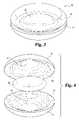
- FIG. 3is a perspective view of an alternative embodiment of a disc prosthesis assembly in accordance with the present invention.
- FIG. 4is an exploded view of the disc prostheses assembly of FIG. 3 .
- FIG. 5is a perspective view of one embodiment of a spinal cervical implant in accordance with the present invention.
- FIG. 6is an exploded view of the spinal implant of FIG. 5 .
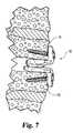
- FIG. 7is an elevated, side view in partial section of the spinal implant of FIG. 5 disposed in a disc space between a pair of vertebrae in accordance with the present invention.
- FIG. 8is a perspective view of another embodiment a spinal implant in accordance with the present invention.
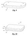
- FIG. 9is a perspective view of one embodiment of a bone plate in accordance with the present invention.
- FIG. 10is a perspective view the of bone plate of FIG. 9 with a polymeric coating in accordance with the present invention.
- FIG. 11is a perspective view of a spinal rod assembly in accordance with the present invention.
- FIG. 12is a perspective view of one embodiment of an implantable, porous tube prepared in accordance with the present invention.
- FIG. 13is a perspective view of one embodiment of a catheter in accordance with the present invention.
- FIG. 14is a perspective view of one embodiment of a cardiac pacemaker comprising a lead formed of a porous metal matrix composite in accordance with the present invention.
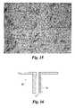
- FIG. 15is a scanned image of a micrograph of a metal matrix composite comprising 10 wt % TiC dispersed in a Ti-6Al-4V matrix.
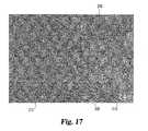
- FIG. 16is a partial view in full section of a multi-layered construct in accordance with the present invention.
- FIG. 17is a scanned image of a micrograph of the construct of FIG. 16 .
- FIG. 18is a scanned image of a micrograph of a cross section of a titanium matrix illustrating the porous structure of the material.
- FIG. 19is a scanned image of an enlarged view of the micrograph of FIG. 18 .
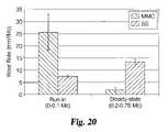
- FIG. 20is a bar graph illustrating the result of wear testing on a titanium carbide (Ti—C) metal matrix composite and a stainless steel metallic material.
- the present inventionprovides a spinal implant assembly for insertion between two adjacent vertebrae.
- the implantcomprises a first structural member including a first surface configured to engage the first vertebrae and an opposite second surface; and a second structural member including a third surface configured to engage the second vertebrae and an opposite fourth surface having a bearing portion configured to engage the second surface of the first structural member.
- the first and second structural members in this embodiment of the inventioncomprise a composite including a metallic matrix and a reinforcing component dispersed within the metallic matrix.
- the reinforcing componentcan be homogeneously distributed throughout the metal matrix composite. In other embodiments, the reinforcing component can be dispersed either in-homogeneously or as a gradient throughout the metal matrix composite.
- the metallic matrixcan include, but is not limited to, one or more of the following materials: titanium, titanium aluminum alloy, zirconium, and niobium.
- the reinforcing componentcan be a ceramic or an inter-metallic material. Non-limiting specific examples of the reinforcing component include TiC, TiB 2 , TiN, TiAl, WC, BC 4 , BN, diamond, ZrO 2 , Al 2 O 3 , and mixtures of these materials.
- the metal matrixcan include a widely varying amount of the reinforcing components.
- the metal matrix compositecomprises between about 10 wt % and about 90 wt % of the reinforcing component based upon the total weight of the metallic matrix composition.
- the metal matrixcomprises between about 10 wt % and about 80 wt %; in still another alternative, the metallic matrix comprises between about 10 wt % and about 40 wt % of the reinforcing component.
- Implants according to the present inventioncan be fabricated to exhibit widely varying physical characteristics.
- the metal matrixcan be fabricated through processes such as sintering to have a density as desired for a particular application.
- the densitycan be greater than about 85%, more preferably greater than about 90%, and more preferably approaching 100%.
- the metal matrix composite according to the present inventioncan exhibit varying degrees of hardness, again depending upon the desired application.
- the metal matrix compositecan be provided as a porous material.
- the porous materialcan serve as a depot for a therapeutic agent and control the release of that therapeutic agent into surrounding tissue.
- the propertiescan be tailored as desired to allow bone ingrowth. Consequently, the properties, percent porosity, average pore size, pore depth, and volume can vary widely depending upon the intended application of the material.
- the implants of the present inventionare fabricated to create a spinal implant.
- the spinal implantcan include a first and second plate and can be used in any application which requires an articulating joint.
- the first and second platecan be configured to matingly match their respective geometries to allow a smooth, facile translation and/or rotation.
- the present inventionprovides a spinal implant assembly for insertion between adjacent vertebrae.
- the spinal implant assemblycomprises a first structural member and a second structural member.
- the first structural membercan include a first surface configured to engage a first vertebrae and an opposite second surface having a first recess therein.
- the second structural membercan include a third surface configured to engage the second vertebrae and an opposite fourth surface having a second recess configured to oppose the first recess in the first structural member.
- An articulating elementis disposed between the first recess and the second recess.
- One or more of the articulating element, the first structural member, and the second structural membercan comprise a metal matrix composite that includes a metallic matrix and a reinforcing component dispersed within the metallic matrix.
- the articulating elementcan be provided in a wide variety of configurations including, but not limited to, spherical, cylindrical, or elliptical geometries.
- the present inventionprovides a medical device.
- the medical devicecomprises an implantable portion for treatment or diagnosis of a patient.
- the implantable portioncan include a first layer comprising a metal matrix composite that includes a metal matrix and a reinforcing component dispersed within the metal matrix.
- the medical devicecan be fabricated in a wide variety of implantable medical devices including, but not limited to, a disc prosthesis, a bone plate, a catheter, a catheter tip, an electrode lead for a pacemaker, and other stimulation electrode.
- the metal matrix composite and reinforcing componentcan be selected from a wide variety of materials. The specific materials are noted above for the other identified embodiments.
- the present inventionprovides a method of treating a spinal defect and/or disorder.
- the treatment methodincludes preparing a disc space between two adjacent vertebrae to receive a spinal implant, inserting a spinal implant assembly, which assembly includes a first structural member having a first surface to engage a first vertebra and an opposite second surface, and a second structural member having a third surface to engage an adjacent vertebra and an opposite fourth surface to bear against the second surface of the first structural member.
- At least one of the first structural member or second structural memberis/are composed of a metal matrix composite that includes a metal matrix including a biocompatible metal or metal alloy and a reinforcing component disposed within the metallic matrix.
- the treatment in accordance with the present inventioncan also include performing a discectomy to remove all or a portion of the dissected disc structure between the adjacent vertebrae.
- the spinal implant assemblycan incorporate a therapeutic agent to treat a medical condition and/or induce bone growth or tissue ingrowth into the implanted assembly.
- the medical devices or implantscan be fabricated to exhibit a wide variety of desirable characteristics including a selected radiolucency which may vary depending upon the mode of treatment, the volume of tissue being treated, and type of device.
- the devicescan be fabricated from a substrate material, such as the metal matrix composite, that exhibits the desirable physical characteristics. Further, when desired for specific applications, the substrate material can be coated with additional coatings or layers or further treated, i.e., a surface treatment such as nitriding, carburizing, or carbonitriding.
- a surface treatmentsuch as nitriding, carburizing, or carbonitriding.
- the present inventionincludes implantable medical devices at least partly formed from a metal matrix composite, for example, metal matrix composites may be overlaid on a metallic substrate.
- medical devicesthat are included within the scope of the present invention include: orthopedic implants, such as spinal implants, disc prostheses, nucleus prostheses, bone fixation devices, bone plates, spinal rods, rod connectors, knees, hip prostheses; cranial implants; drug delivery implants such as stents, implantable tubes or capsules, and catheter tips; electrical conducting leads, such as leads for sensors, pacemakers, and electrodes, i.e., a stimulation electrode or a monitoring electrode; cardiovascular implants, such as stents; and the like.
- the medical devices of the present inventioncan be used to treat a wide variety of animals, particularly vertebrate animals and including humans.
- the medical devices based on this inventionare formed of novel materials for use in implantable medical devices.
- the present inventionprovides an orthopedic device that exhibits enhanced wear characteristics. These devices are particularly advantageous for use in articulating joints such as spinal implants and disc or nucleus prostheses, which are used to treat spinal defects.
- the present inventionprovides medical devices that include a porous metallic structure that can be fabricated as a composite. The porous structure can facilitate tissue ingrowth into the implanted medical device.
- the porous structurecan be impregnated with a therapeutic agent such as a drug, growth factor, proteins, and the like, to elicit a targeted chronic or acute biological response.
- Pore characteristics such as size and depthcan be engineered to attain a desired elution rate (acute or chronic) of one or more therapeutic agents.
- the porous structurecan provide a substrate with a surface layer that can adhere and retain a coating via a mechanical interlocking mechanism.
- the applied coatingcan be a metallic coating, a polymeric coating, or a coating employing endogenous materials.
- the coating and/or the underlying porous structurecan be impregnated with a therapeutic composition to treat one or more medical conditions.
- FIG. 1is an elevated side view of one embodiment of disc prosthesis 10 for implantation in a disc space between a pair of vertebrae in accordance with the present invention.
- Prosthesis 10is illustrated comprising two basic components: a first structural member, such as a first plate 12 , and a second structural member, such as second plate 14 .
- First plate 12 and second plate 14bear against each other at interface 15 .
- FIG. 2is an exploded view of prosthesis 10 .
- First plate 12comprises a first surface 16 as an upper bone engaging surface, an opposite second surface 18 , and a sidewall 17 therebetween.
- First surface 16is provided in a configuration selected to engage with a first, opposing vertebral endplate (not shown).
- First surface 16can include a curved surface portion to matingly conform with and engage with the endplate of the opposing vertebra.
- first surface 16can be configured to engage with the inferior endplate of a cervical vertebral body.
- prosthesis 10can be sized to be inserted between any two articulating vertebrae, for example, thoracic, lumbar, and even between the L5 lumbar and the S1 sacral vertebrae.
- first surface 16can either be substantially planar or have a flat surface portion. It will also be understood that the endplate of a particular vertebra can be cut and/or shaped during surgery to receive the disc prosthesis and to securely engage with a planar first surface 16 .
- First surface 16can include one or more bone engaging structures on the entire surface or surface portions, to ensure secure attachment to the vertebra.
- bone engaging structuresinclude teeth, ridges, grooves, rails, a porous surface layer, coating layer(s) formed of a different metallic material, a polymeric material, or a ceramic material (e.g. hydroxyapatite, and the like).
- plate 12can have one or more openings, apertures, or bores 20 and 21 through which a bone fastener such as a screw (not shown) can be inserted to secure plate 12 to the vertebral body.
- first surface 16can be formed of a metal matrix composite material, metal, or alloy that exhibits a predetermined, or controlled or selected porosity.
- the pore sizecan be varied as desired for a use in a particular application.
- the pore sizecan be selected to allow bone ingrowth into the metal matrix composite.
- the pore sizecan be controlled or selected to be between about 10 microns ( ⁇ ) and about 500 ⁇ .
- the pore sizecan be between about 25 ⁇ and about 200 ⁇ ; or between about 50 ⁇ and 150 ⁇ as desired for a particular application.
- the pore sizecan also be controlled or selected to facilitate use of the implant as a depot for one or more therapeutic agents or to facilitate the release of therapeutic agents into adjacent tissue. Further, the pore size can be varied and optimized, as desired, to allow a controlled delivery rate of the agents(s); the controlled delivery rate can be for either chronic and/or acute treatment.
- Second plate 14comprises a third surface 24 , an opposite fourth surface 26 , and a side wall 27 therebetween.
- Third surface 24is provided in a configuration to engage with the endplate of an opposing vertebra (not shown) similar to first surface 16 .
- surface 24is configured to engage with the superior surface of a cervical vertebra.
- third surface 24also can include bone engaging structures including teeth, ridges, grooves, keel, rails, a porous surface layer, coating layer(s) as noted above, and/or one or more apertures or bores 28 and 29 .
- a bone fastenersuch as a screw, can be inserted through each of the one or more apertures 28 to secure plate 12 to the bone tissue.
- second surface 18 and fourth surface 26In use, when inserted between a disc space between two adjacent vertebrae, second surface 18 and fourth surface 26 exhibit a sliding and/or rotating engagement with each other. Consequently, second surface 18 and fourth surface 26 are individually shaped to matingly conform to each other.
- second surface 18exhibits a convex shape
- fourth surface 26exhibits a concave shape.
- Each of second surface 18 and fourth surface 26define wear surfaces 30 and 32 , respectively, which are formed of a material selected to exhibit enhanced wear characteristics.
- the materialcan be selected as a metal matrix composite with a reinforcing component uniformly or non uniformly dispersed therethrough.
- surfaces 30 and 32are characterized to have a minimum surface hardness of greater than about 20 Rc; more preferably, greater than about 45 Rc. With increasing amounts of the reinforcing component, the surface hardness can increase.
- first plate 12 and second plate 14comprise a metal matrix composite that includes a base metal or metal matrix with a reinforcing component interspersed therein.
- the reinforcing componentis not just a surface coating of the reinforcing component.
- the reinforcing componenthas been dispersed either homogeneously or in-homogeneously throughout the matrix or the matrix layer. Incorporation of reinforcing component throughout the matrix or matrix layer provides a metal matrix composite that exhibits “bulk hardness”.
- the metal matrix compositecan exhibit varying properties or characteristics selected to provide enhanced wear characteristics. The metal matrix composite is discussed more fully below. In one form, the metal matrix composite exhibits a density approaching 100%.
- the metal matrix compositeexhibits a density that can be varied depending upon the desired application.
- one or more of the first or second structure memberscan have a less dense core. This can be accomplished by selectively increasing the porosity of the core.
- Prosthesis 10is illustrated to exhibit a bi-convex lens, cross sectional shape. In other embodiments, it will be understood that the shape of prosthesis 10 can be varied to include a wedge shape or lordotic shape to correct or restore a desired disc space height or spinal column orientation.
- Prosthesis 10can be provided in a size and a shape to promote the desired therapy to treat the spinal defect. Consequently, prosthesis 10 can be provided in a size to fit between adjacent vertebrae such as the cervical vertebrae, the thoracic vertebrae, the lumbar vertebrae, and the sacral vertebrae. Prosthesis 10 can be sized to extend laterally across the entire surface of the endplate of the opposing vertebrae. More preferably, prosthesis 10 can be sized to extend laterally to bear against the apophyseal ring structure. Prosthesis 10 can extend anterior and posterior across the entire endplate of the opposing vertebrae. In the illustrated embodiment, when viewed from above, prosthesis 10 is configured to resemble a shape with a matching geometry to interface with the opposing endplates of the adjacent vertebrae.
- first plate 12 and second plate 14each can be formed as a monolithic metal matrix composite.
- the metal matrix composite composing the first and second plates 12 and 14can comprise a metal matrix including a titanium matrix or a titanium alloy.
- a reinforcing componentis dispersed throughout the metal matrix. The matrix material and the reinforcing component are discussed more fully below.
- first plate 12 and second plate 14can be made of one or more layers or regions.
- the one or more layerscan be either vertical layers, i.e., layered or laminated one on top of another from first surface 16 to second surface 18 or horizontal layers laminated laterally and/or anterior-posterior, side by side each other (considering the placement of the implant in the spinal column).
- the different layers or regionscan be composed of the same or different metal matrices or composites (different alloy systems). If the different layers contain different composites, the different composites can contain different constituents or the same constituents in differing amounts.
- first surface 16can be formed of a first material that includes a first metal matrix composite having a first reinforcing component dispersed therein or, alternatively, no reinforcing component therein.
- first metal matrix compositecan be provided to exhibit a selected porosity sufficient to allow tissue integration or ingrowth to enhance the secure attachment of the implant to the vertebra and/or delivery of therapeutic agents.
- Second surface 18can be formed of a second material selected to enhance the wear capability and increase the useable life span of the implanted prosthesis.
- second surface 18can be formed of a second metal matrix material having a sufficient hardness to reduce wear or material loss from the surface in use.
- second plate 14can be formed of yet another material selected to enhance the image capabilities of the implant when examined using common diagnostic imaging techniques, such as x-ray (including fluoroscopy), CT, or MRI scanning techniques. Consequently, second plate 14 can be provided as a laminated structure with two, three, or more layers. The metal matrix material and/or the reinforcing component in the composite or their concentrations can differ between the different layers.
- second plate 14can be provided as a single material formed of a metal matrix composite having the reinforcing component distributed therethrough in a homogeneous or non-homogeneous manner.
- the reinforcing componentcan be dispersed within the matrix in a concentration gradient that varies from the second surface 18 to the first surface 16 .
- the relative concentration of the reinforcing material in the matrixcan increase from a low value proximate to first surface 16 to a maximum value near or at second surface 18 .
- the identity of the reinforcing component or the metal matrix materialcan vary or change from the different layers or even between different regions of the prosthesis.
- a third structural membercan be positioned between the first plate 12 and second plate 14 .
- This third structural member, attached or floating,can comprise a polymeric, ceramic, or metallic material.
- the metallic materialcan be the same or different from the metal matrix composite.
- the polymeric materialcan be either biodegradable or biostable, examples of which are discussed more fully below.
- this third structural componentcan comprise a uniform plate with a round, oval, or endplate matching configuration.
- the third structural membercan comprise a donut-like shape.
- the interior cavity of the “donut”may or may not be filled with a therapeutic agent.
- FIG. 3is a perspective view of an alternative implant assembly 36 in accordance with the present invention.
- Implant assembly 36includes an upper, or first plate 38 , an opposing, lower or second plate 40 , and an articulating element 42 disposed therebetween.
- articulating elementengages or rests within a first depression, receptacle, or recess 44 in first plate 38 and in an opposing depression or second receptacle 46 in second plate 48 .
- Articulating element 42is illustrated as a curved element, preferably having an ovoid shape and/or having a round or oval cross-sectional shape.
- articulating elementcan be provided in a variety of other shapes including spherical, cylindrical or elliptical, disk shape, flattened shape, or wafer and the like.
- Articulating element 42can be composed of a metallic material, preferably a metal matrix composite as discussed herein.
- First plate 38can be provided substantially as described above to first plate 12 for implant 10 , including the bores for bone fasteners, such as screws, and bone engaging surfaces. Additionally first plate includes recess 44 on its underneath surface 39 , opposite the upper or bone engaging surface 41 .
- Recess 44can be composed or coated with a layer of material that is the same or different from the material forming the bulk of first plate 38 .
- the layer of material coating the recess 44is composed of a metal matrix composite.
- the metal matrix compositecan be the same or different from the material that forms the articulating element 42 .
- Second plate 40can be formed similar to first plate 38 including the bores and bone engaging surfaces. Further, second plate 40 includes a second recess 46 that can oppose first receptacle 44 when the implant is fully assembled. Recess 46 can be configured and formed similar to that described above for receptacle 44 including the selection of material and/or coating or layer of material such as the metal matrix composite that is different from that forming the bulk of the second plate 40 .
- FIG. 5illustrates an alternative embodiment of a prosthesis or spinal implant 50 .
- Implant 50includes exterior configuration similar to that which has been previously described in U.S. Pat. No. 6,113,637, which is hereby incorporated by reference in its entirety.
- Implant 50includes an upper portion 52 and a lower portion 54 .
- upper portion 52is spaced from lower portion 54 .
- Upper portion 52includes a first surface 56 and an opposite, second surface 58 .
- first surface 56is substantially planar. However, as described above for implant 10 , first surface 56 can be provided to include a wide variety of features or structures selected to engage with the endplate of an opposing vertebra. Examples of tissue-engaging structures include teeth, ridges, pores, grooves, roughened surfaces, wire mesh, and the like. Additionally or in the alternative, surface 56 can include tissue-engaging structures such as ridge 60 illustrated.
- a first flange 62extends from upper portion 52 . Flange 62 can have one, two, or more apertures 64 extending therethrough. Aperture 64 can be a smooth bore or a threaded bore.
- a bone fastener 66can be threaded or inserted through aperture 64 and then secured into bone tissue. Bone fastener 66 can be any bone fastener known, described, and/or commonly used for orthopedic applications including screws, staples, wires, pins, rods, sutures, and the like.
- a protuberance or hemi-spherical projection 70extends downwardly from second surface 58 .
- Projection 70defines a bearing surface that engages with lower portion 54 .
- projection 70is formed of a first metal matrix composite.
- the first metal matrix compositeexhibits a hardness selected to enhance and extend the useful life span of the implant as it operates or is intended to operate as a disc prosthesis with minimal wear and limited debris loss to the surrounding environment and tissue.
- the first metal matrix compositecan be the same material or a different material used to form the residual portion of second surface 58 and/or the upper portion 52 .
- Lower portion 54includes a third surface 72 , which has a trough 74 formed therein.
- Trough 74is configured to receive or seat projection 70 therebetween.
- trough 74is configured to allow projection 70 and consequently upper portion 52 to rotate or partly rotate about three orthogonal axes and translate or slide along in at least one direction.
- trough 74allows upper portion 52 to slide in the anterior to posterior (AP) direction, referring to the orientation (translation) of the prosthesis in the disc space.
- the upper portion 52 and lower portion 54can, but need not, be formed of the same material.
- upper portion 52can be formed of a first biocompatible material, which may or may not be a metal matrix composite and lower portion 54 can be formed of a second biocompatible material, different from the first material.
- the second materialalso, can, but need not, be formed of a metal matrix composite.
- the non-metal matrix composite materialscan comprise one or more of a polymeric material—either biodegradable or not, a ceramic material, a metallic material, or a pure metal or alloy material.
- the trough portion 74 of the third surface 72is formed of a metal matrix composite that exhibits enhanced wear characteristics.
- the third surface 72 and the body 73 of lower portion 54are formed of the same metal matrix composite.
- Lower portion 54also includes a fourth surface 76 opposite the third surface 72 .
- Fourth surface 76can be provided to securely engage with the opposing vertebra and can include tissue engaging structures as has been described above for the first surface 56 .
- lower portion 54can include a second flange 78 extending therefrom. Second flange 78 can be configured substantially as has been described for first flange 62 , including one or more bore or apertures 80 through which bone fasteners can be inserted to engage with underlying tissue.
- protuberance 70is separable or non-integral with second surface 58 of upper portion 52 .
- second surface 58includes a recess or trough similar to trough portion 74 formed therein.
- the non-integral protuberance 70is disposed between trough 74 and the trough formed in second surface 58 .
- the non-integral protuberancecan comprise a metal matrix composite that is the same or different from that included in either the upper portion 57 or lower portion 54 .
- the non-integral protuberancecan be provided in a wide variety of shapes including round, or spherical, elliptical, and cylindrical.
- protuberance 70can comprise any biocompatible material including polymers—either biodegradable or not, metallic materials, and metal alloys.
- FIG. 7is an elevated side view illustrating the positioning of spinal implant 50 in a disc space between two adjacent cervical vertebrae 84 and 86 .
- Implant 50can be positioned in any position in the disc space.
- FIG. 8is a perspective view of yet another embodiment of a spinal implant 100 in accordance with the present invention.
- Implant 100is provided as an assembly that includes two basic, separable components: a first or upper portion 102 and a second or lower portion 104 .
- Upper portion 102can be provided substantially as has been described for upper portion 52 of implant 50 .
- upper portion 102includes two flanges 106 and 108 that are configured to overlay bone tissue.
- Preferably flanges 106 and 108are configured to overlay the anterior vertebral body wall portion.
- Each flange 106 and 108has at least one bore or aperture 109 and 111 , respectively, through which a bone fastener can be inserted.
- a first, upper surface 110includes two rails 112 and 114 extending therefrom. Rails 112 and 114 are linear and extend along the upper, bone engaging surface 115 parallel to each other. However, it will be understood that rails 112 and 114 need not be linear or parallel to each other.
- the two rails 112 and 114each can include teeth or ridges and other surface structures, as noted below, to provide a secure engagement with the opposing endplate of an adjacent vertebra (not shown).
- Lower portion 104can be provided substantially as has been described for lower portion 54 of implant 50 . Further, lower portion 104 includes two flanges 120 and 122 extending downwardly from an anterior wall 124 (each flange 120 and 122 can include at least one bore or aperture) and a pair of rails as has been described for the upper portion 102 .
- FIG. 9is a perspective view of one embodiment of a bone plate 130 in accordance with the present invention.
- Bone plate 130can comprise a metal matrix composite described more fully below.
- Bone plate 130is illustrated as a laminated structure with two layers. It is to be understood that laminated bone plates comprising three, four, five, or more layers are considered to be included within the scope of the present invention.
- the different layerscan be formed of the same or different constituents. If the layers are formed of the same constituents, then the two layers may be fabricated differently to exhibit differing properties.
- bone plate 130includes a first layer 132 .
- Layer 132is provided to contact or engage with bone tissue.
- layer 132comprises a material that can include a porous metal or a porous metal matrix composite discussed more fully below.
- the porous metal matrix composite materialcan be impregnated with a first therapeutic composition or agent.
- the therapeutic compositioncan include one or more of the therapeutic agents, such as a drug, a bone growth inducing component or factor, nutrients, hormones, analgesics, antibiotics, antimicrobials, antifungal, and combinations of these components.
- the therapeutic composition or agentcan slowly diffuse out of or adhere into the porous matrix to provide a beneficial effect. For example, faster osteointegration to the bone defect or disorder or elution of the therapeutic agent to the surrounding tissue and/or the patient.
- porous matrixcan exhibit an additional beneficial effect by providing a porous substrate for tissue integration or ingrowth into the plate to facilitate secure engagement of the plate with the bone or surrounding tissue.
- bone contacting surfacessuch as surface or layer 132 can include a sintered layer over an integrated porous layer to attain bimodal porosity.
- the differing layerscan be used to absorb one, two or more therapeutic agents and allow two or more elution rates for the agents.
- Bone plate 130also includes a second layer 134 .
- second layer 134can be positioned opposite the bone defect, disorder, or bone tissue.
- Second layer 134can be composed of a) comprises a metallic material, b) a metal matrix composite, which can be the same or different from layer 132 , or c) a biocompatible polymeric material, which can be either a biodegradable or a biostable material. Additionally, layer 134 can be impregnated with a second therapeutic composition or agent that is the same or different from the first therapeutic composition.
- the porous matrix of the first layer and/or the second layercan also serve to increase the structural integrity of the laminated structure by allowing the two layers to adhere to each other using a mechanical interlocking mechanism where material from one (or both) of the layers can be integrated within the porous structure when present in the opposing layer.
- the additional layer(s)can be include sintered beads, a ceramic material, such as, hydroxyapatite etc to promote bone ingrowths, or one or more reservoirs, for example, one large reservoir or bimodal reservoirs (inner and outer) for elution and delivery of one or more therapeutic agents.
- FIG. 10is a perspective view of yet another embodiment of a bone plate 140 in accordance with the present invention.
- Bone plate 140is a tetra-laminated structure and can include the basic components or layers as described above for plate 130 . Consequently, the same reference numbers will be used to refer to similar or identical components.
- Bone plate 140includes a first layer 132 and a second layer 134 as described above.
- First layer 132can be coated with a polymeric material 136 .
- Material 136can be disposed between first layer 132 and the bone tissue.
- Polymeric material 136can comprise a biodegradable or biostable agent. Further, the polymeric material can, but is not required to, include a therapeutic composition or agent either absorbed within the polymeric material or within pores formed in the polymeric material.
- the therapeutic agent impregnated in the polymeric materialcan either replace or be used in addition to the therapeutic agent absorbed within first layer 132 . Varying the constituency, structure, composition and thickness and properties of the polymeric material can vary the rate of release of the encapsulated therapeutic composition. If the first layer 132 also includes a therapeutic composition, the resulting medical implant can exhibit at least two distinct drug release rates or exudation profiles.
- a second coating 138coats second layer 134 .
- Second coating 138can be provided as described for first polymeric material 136 . However, it will be understood that the polymeric material and/or therapeutic composition for the second coating can, but need not, be the same as that in the polymeric material for the first coating.
- suitable polymers for use in the present inventioninclude a wide variety of biocompatible polymers.
- suitable polymers for use in the present inventioninclude a wide variety of biocompatible polymers.
- non-degradable polymersinclude but are not restricted to: acrylics, fluorocarbons, hydrogels, polyacetal, polyamide, polycarbonate, polyester, poly (aryl ether ketone) (PAER), poly(ether ketones) (PEK), poly(ether ether ketones) (PEEK), polyimides, polyolefins, polystyrenes, polysulfones, polyurethanes, poly(vinyl chloride) (PVC), poly (ether, ketone, ketone) (PEKK), silicone rubbers, and polyethylene.
- PAERpoly(aryl ether ketone)
- PEKpoly(ether ketones)
- PEEKpoly(ether ether ketones)
- polyimidespolyolefins, polystyrenes, polysulfones, polyurethan
- bio-degradable polymersfor use in the present invention include, but are not limited to, poly(amino acids), polyanhydrides, polycaprolactones, polylactates (PLA), polyglycolates (PGA), poly(lactic-glycolic acid) (PLG), and polyorthoesters.
- FIG. 11is a perspective view of a spinal rod assembly 150 comprising a first spinal rod 152 , a second spinal rod 154 , and an interconnection assembly 156 .
- spinal rods 152 and 154can be provided as a metal matrix composite comprising a reinforcing component dispersed therein.
- one or more components of interconnection assembly 156can be provided as a metal matrix composite.
- the interconnection assembly 156includes a first connecting rod member 158 , an interconnection element 160 , and a second connecting rod member 162 .
- spinal rod assembliescan be found in the following patents: U.S. Pat. Nos. 4,641,636; 5,147,360; 6,293,949; and 6,152,927.
- Rods 152 and 154 and/or connecting rods 158 and 162can be secured to portions of the spine, particularly to selected vertebral bodies using bone fasteners 164 and 166 .
- bone fastenerstypically, two or more bone fasteners are used to attach each rod to the spine.
- the spinal rod assembly 150is provided to include one or more components formed of a metal matrix composite to provide distinct advantages in that the connection between one or more of the spinal rod connectors 158 and 162 with the respective spinal rods 152 and 154 provide enhanced strength and resistance to slippage of the interconnection assembly. This provides obvious advantages in minimizing the risk of further damage and requiring revisitation to either correct and/or retighten one or more components of a spinal rod assembly 150 .
- only a section of the rodcan be a composite material for use in applications were varying mechanical properties such as stiffness along the length of the rod is desired.
- FIG. 12is a perspective illustration of a cylindrical tube 170 .
- Tube 170can be provided as a component of an implantable device such as a catheter, electrical lead of a pacemaker, a stent assembly, and the like.
- Tube 170can be provided as a monolithic structure having a uniform composition throughout.
- the monolithic structurecan be formed of a biocompatible metal or metallic matrix such as pure titanium or a titanium alloy, and a reinforcing component dispersed into the matrix.
- tube 170can be provided as a laminated structure similar to bone plates 130 and 140 .
- tube 170can be provided with a porous exterior or interior surface to allow impregnation of either an osteogenic material/agent or other therapeutic agent, which can slowly leach out into the surrounding tissue.
- a coating, or sintered particles or beadscan be incorporated on the exterior surfaces to accomplish a desired therapeutic treatment.
- FIG. 13is a perspective view of one embodiment of a catheter 180 comprising a implantable, metallized portion 182 .
- the implantable metallized portioncomprises a catheter tip 184 .
- Catheter tip 184comprises a metal matrix composite having a reinforcing component dispersed therethrough as discussed more fully below.
- the metal matrix compositecan include a porous metal matrix or a dense matrix depending upon the desired properties and applications.
- the catheter tip 184can be impregnated with one or more therapeutic agents. Additionally, tip 184 will exhibit good imaging characteristics under standard radiographic and MRI imaging techniques. This will allow the surgeon or other health care provider to monitor the catheter and surrounding tissue with greater accuracy and detail.
- FIG. 14is an illustration of a dual lead or dual chamber cardiac pacemaker assembly 190 with a pair of electrical leads 192 and 194 .
- Either one or both of electrical leads 192 and 194can comprise a metallized component or tip 191 that includes a porous metal matrix composite having a reinforcing component dispersed therethrough.
- the metal matrix composite in tip 191defines a pacing electrode with a porous surface area that results in a lower polarization and interfacial impedance.
- the porous metal matrix compositecan provide a depot for a therapeutic composition as above discussed for the bone plate 130 .
- the metallic matrix composite for use in the present inventionis selected to be biologically and/or pharmacologically compatible. Further, the preferred composites exhibit minimal or no toxicity, either as the bulk device or in particulate or wear debris form. The individual components in the matrix are also pharmacologically compatible. In particularly preferred embodiments, the metallic matrix composite includes at least one component that has been accepted for use by the medical community, particularly the FDA and surgeons.
- the metal matrix composite of the present inventionincludes at least one base metal or metal alloy that provides a metal matrix and a reinforcing component interspersed within the metal matrix.
- the base metal or metal alloycan be selected from a variety of biocompatible metals and metal alloys. Specific examples of biocompatible metals and metals for use in the present invention include titanium, titanium alloys, zirconium, niobium, stainless steel, cobalt and its alloys, tantalum and its alloys, and mixtures of these materials.
- the metal matrix compositeincludes a commercially pure titanium metal (CpTi) or a titanium alloy.
- titanium alloys for use in the present inventioninclude Ti-6Al-6V, Ti-6Al-6V-2Sn, Ti-6Al-2Sn-4Zr-2Mo, Ti-V-2Fe-3Al, Ti-5Al-2.5Sn, and TiNi. These alloys are commercially available in a purity sufficient for the present invention from one or more of the following venders: Allvac; Timet Industries; Specialty Metals; and Teledyne WaChang.
- the metal matrix compositealso includes a reinforcing component as a discrete component of the matrix.
- the reinforcing componentcan be observed as a separate phase in the metal matrix composite.
- the reinforcing componentis a crystalline structure exhibiting a distinct grain morphology and/or size from that observed in the bulk matrix. While observed as a discrete component of the bulk matrix, it is believed that the reinforcing component imparts or influences the microstructure of the surrounding metallic matrix.
- the reinforcing componentimparts enhanced wear characteristics to the matrix.
- the selection of the reinforcing component and selection of specific fabricating proceduresprovides a metal matrix composite with higher hardness, improved wear resistance, improved strength, and increased tissue integration and ingrowth.
- the reinforcing componentis a hard material and/or a refractory material.
- reinforcing components for use in the present inventioninclude ceramics, refractory metals, metal carbides, metal nitrides, metal borides, and diamonds.
- Specific examples of reinforcing components for use in the present inventioninclude W, TiC, TiN, TiB 2 , TiAl, WC, BC 4 , BN, diamond, zirconium oxide, aluminum oxide, and mixtures thereof.
- the metal matrix compositecomprises a sufficient amount of the reinforcing component to provide a composite having suitable hardness to resist or reduce either wearing away under stress and/or repeated movement. This can be particularly important for articulating implants that are configured to bear against either another hard surface or a mating component such as found in a disc or nucleus pulposus prosthesis, knee prosthesis, hip prosthesis, and other wear couples.
- the reinforcing componentcan be added to the matrix in a desired amount.
- the desired amountcan be selected for the intended application of the device.
- the implants formed of the metal matrix compositecan be further treated as desired for a particular application.
- the surfaces of the implantwhether composed of the metal matrix composite, an alloy, etc., can be subjected to secondary ion implantation, surface hardening (carbonizing, nitriding, carbonitriding), interstitial hardening can be employed on the articulating surfaces.
- medical implantsmay be fabricated to a high degree of precision and under strict tolerances. Depending upon the manufacturing techniques, which are discussed below more fully, fabrication of the medical device may require extensive machining and/or finishing steps. Extremely hard materials are equally hard to machine, which can be expensive and time consuming. Consequently, the proper selection of the amount of reinforcing component incorporated into the metal matrix composition is an important aspect to consider when designing and fabricating the implantable medical devices of the present invention.
- the metal matrix compositioncan include between about 1 wt % and about 90 wt % of the reinforcing component, based upon the total weight of the resulting metal matrix composition. More preferably, the metal matrix composite of the present invention includes between about 10 wt % and about 80 wt % of the reinforcing component; still more preferably, the metal matrix composite includes between about 10 wt % and about 40 wt % of the reinforcing component. In particular applications, it may be desirous to include between 10 wt % and 30 wt % of the reinforcing component into the metal matrix composition.
- the metal matrix composite of the present inventioncan be fabricated to exhibit extreme hardness and increased wear characteristics. By incorporating a desired amount of the reinforcing component into the metal matrix, the hardness of the resulting composition can be significantly increased.
- the metal matrix composites according to the present inventioncan be fabricated over a wide hardness range depending upon the composition of the metal matrix, the reinforcing component, the shape and size of the particles, and post thermal and/or mechanical treatment.
- the metal matrix composites for use in the present inventioncan be prepared to exhibit a hardness of greater than about 20 Rc, or greater than about 45 Rc.
- the reinforcing componentcan exist in the metallic matrix as discrete particles or as a separate phase.
- the shape (circular, irregular, high aspect ratio, etc) of the reinforcing componentcan be selected to attain specific properties, such as isotropic or non-isotropic.
- particle sizecan play an important role.
- the particlescan be found either as platelets, grains, whiskers, or slivers depending upon the method of preparation, the identity of metallic matrix composition, the identity of the reinforcing component, and the amount of the reinforcing component added to the matrix or any secondary fabrication steps such as casting.
- the metal matrix compositecan be provided with a wide variety of microstructures. In preferred embodiments, the metal matrix composite is provided to have an extremely fine microstructure for the matrix material.
- the grain structure for the matrix materialcan be tailored depending upon the method of manufacture.
- the reinforcing componentcan exhibit a grain size from about 2 ⁇ to about 50 ⁇ . In specific embodiments, the reinforcing component can be found in the matrix in a substantially uniform size distribution. In other embodiments in a single matrix composite, the reinforcing component can in exist in varying sizes, for example, in an averaged bimodal average grain size or an averaged multimodal grain sizes. Grain size can be controlled by starting particle size, sintering temperature, post hipping heat treatment, mechanical and thermo-mechanical processing, just to name a few processing parameters.
- the metal matrix composites of the present inventioncan exhibit various densities depending upon the method of manufacture.
- High density matrixesfind particular advantageous use in implants with surfaces that bear against and either rotate and/or slide against each other.
- these metal matrix composites for use in the present inventioncan have a density of greater than about 80% or 85%. More preferably, the metal matrix composite of the present invention can have a density of greater than about 90%; more preferably, between about 95% and 100%.
- FIG. 15is a scanned image of a micrograph of a metal matrix composite including Ti-6Al-4V and 10-wt % TiC dispersed therein.
- Reference number 198refers to the bulk Ti-6Al-4V matrix, and reference number 199 refers to the TiC particles.
- the materialwas prepared by powder compaction then cast. Following casting, a rod can be processed further to modify mechanical properties, as needed
- Phases of the titanium metal matrixcan contain more than one phase; typically alpha and beta phases are found.
- the ratio of alpha to beta phasescan vary. For example, in 10-wt % TiC in Ti-6Al-4V, the alpha phase predominated, while in the 10 wt % W in Ti-6Al-4V, the alpha and beta phases were found in roughly the same ratio.
- the area of the matrix material immediately surrounding the reinforcing componentcan differ from the bulk matrix. For example, the area immediately surrounding the W in Ti-6Al-4V was almost exclusively beta phase. Consequently, the identity (and amount) of the reinforcing component in the matrix influences the microstructure of the matrix material.
- the metal matrix compositecan be prepared by first blending the metal matrix material and the reinforcing component to provide a uniform powdered mixture. Next, the uniform powdered mixture is subjected to pressure such as cold isostatic pressure. This provides a mechanical bond between the microcomposited materials. However, since the temperature is maintained below the melting temperature of either the reinforcing component or the metal matrix composite, no diffusion occurs between the two components.
- the porous metal matrix compositecan be manufactured using hot isostatic pressing (HIP) usually under vacuum or an inert atmosphere, i.e., nitrogen argon, or mixtures thereof.
- HIPhot isostatic pressing
- the powdered mixtureis heated to a temperature less than the melting temperature of either the metal matrix or the reinforcing component.
- FIG. 16is a partial view in full section of a layered construct 200 in accordance with the present invention.
- Layered construct 200can represent any of the implantable devices described above more fully. As can be seen in the layered construct 200 can compose two layers, 202 and 204 , which can be two different materials or matrices.
- Metal matrix composite 206includes a first layer 208 of a metal matrix composite with a reinforcing component 210 dispersed within a metal matrix 206 .
- the first layer 208is laminated over a second layer 212 .
- Second layer 212includes little or no reinforcing component dispersed with in the matrix 210 .
- the layer constructcan be prepared by laser melting and deposition of a composite powder on a substrate or by using sintering and either cold isostatic pressing (CIP) or hot isostatic pressing (HIP) techniques.
- CIPcold isostatic pressing
- HIPhot isostatic pressing
- the implants according to the present inventioncomprising a metal matrix composite that can be fabricated using a metal injection molding (MIM) technique.
- MIMmetal injection molding
- the metal matrix material, the reinforcing component, and an organic bindercan be blended together.
- the resulting mixturecan then be injected molded into a near net shape of a desired implant.
- This techniquecan allow rapid fabrication of complex shapes and implant designs with minimal finish machining.
- the molded article or “green” articlecan subsequently be treated using a variety of techniques including CHIP, CIP, HIP, sintering, and densifying as is known in the art.
- the implants comprising a highly dense metal matrix composite of the present inventioncan be prepared by a variety of rapid prototyping techniques. Such techniques include stereolithography, selective laser sintering, and laser-engineered net shaping (LENS), to name just a few.
- rapid prototyping techniquesinclude stereolithography, selective laser sintering, and laser-engineered net shaping (LENS), to name just a few.
- porous metal componentscan be prepared by using a thermal spraying technique in which the powdered mixture is used to form a metal matrix composite using a plasma spray technique.
- the thermal heatmay also be used as a combustion flame, an electric arc, or a plasma flame to prepare the porous metal matrix composite.
- the metal matrix composite material for use in the present inventioncan be prepared to exhibit a predetermined, or controlled or selected porosity.
- a porous metal matrix composite is desired materialcan be prepared to have a porosity of greater than about 5% or greater than about 10% and in another embodiment of greater than about 40%.
- the pore sizecan be varied widely depending upon the desired application.
- the pore sizecan be selected to allow bone ingrowth into the metal matrix composite.
- the preferred pore sizecan be controlled or selected to be between about 10 microns ( ⁇ ) and about 500 ⁇ . More preferably, the pore size can be between about 25 ⁇ and about 200 ⁇ ; still more preferably between about 50 ⁇ and 150 ⁇ .
- the pore size as used hereincan be determined according to ASTM Standard F1854-01 entitled “Standard Test Method for Stereological Evaluation of Porous Coatings on Medical Implants”
- the pore sizecan be controlled or selected by varying the constituents of the metal matrix composite. Alternatively, the pore size can be controlled by varying selected process parameters, such as the sintering temperature and pressure. Typically, larger particles induce greater porosity into the matrix.
- the particle shapecan also influence the porosity of the matrix. Generally, particles that do not pack well will increase the porosity of the matrix composite. For example, non-uniform or greater irregularly shaped particles, particles with a high aspect ratio, and selecting particles from a wide size distribution will increase the porosity of the matrix composite. Changing the sintering temperature also can impact the porosity of the matrix composite. Increasing the sintering temperature decreases the porosity.
- the pore sizecan be controlled or selected to facilitate use of the implant as a depot for one or more therapeutic agents or to facilitate the release of the therapeutic agents into adjacent issue. Further, the pore size can be varied and optimized, as desired, to allow a controlled delivery rate or the agents(s); the controlled delivery rate can be for either chronic treatment and/or acute treatment.
- FIGS. 18 and 19are scanned images of micrographs of a cross sectional slice of a commercially pure titanium that exhibits a porous structure.
- the metal matrix composite of the present inventioncan be processed to exhibit the same or similar physical characteristics.
- ExampleFor the purpose of promoting further understanding and appreciation of the present invention and its advantages, the following Example is provided. It will be understood, however, that this Example is illustrative and not limiting in any fashion.
- the two material pairshad different wear rates for run-in and steady-state conditions ( FIG. 20 ).
- the MMCdemonstrated a higher run-in wear rate than SS but had almost an order of magnitude lower steady-state wear rate.
- the MMChad a substantially lower wear amount than the SS as well as a lower wear rate.
- one station with a SS pairingleaked, giving much higher wear rates under dry conditions, and thus it was excluded subsequently from the tests.
- the MMC(TiC+Ti 6 Al 4 V) exhibited superior wear performance.
- titanium-based MMCis a feasible material for metal-metal cervical spine implants, in that it has shown superior wear performance compared with the currently used SS.
- any reference to a specific directionfor example, references to up, upper, down, lower, and the like, is to be understood for illustrative purposes only or to better identify or distinguish various components from one another.
- Any reference to a first or second vertebra or vertebral bodyis intended to distinguish between two adjacent vertebrae and is not intended to specifically identify the referenced vertebrae as first and second cervical vertebrae or the first and second lumbar, thoracic, or sacral vertebrae.
- These referencesare not to be construed as limiting any manner to the medical devices and/or methods as described herein. Unless specifically identified to the contrary, all terms used herein are used to include their normal and customary terminology.
- various embodiments of medical devices having specific components and structuresare described and illustrated herein, it is to be understood that any selected embodiment can include one or more of the specific components and/or structures described for another embodiment where possible.
Landscapes
- Health & Medical Sciences (AREA)
- Orthopedic Medicine & Surgery (AREA)
- Life Sciences & Earth Sciences (AREA)
- Engineering & Computer Science (AREA)
- Veterinary Medicine (AREA)
- Biomedical Technology (AREA)
- Public Health (AREA)
- General Health & Medical Sciences (AREA)
- Animal Behavior & Ethology (AREA)
- Neurology (AREA)
- Chemical & Material Sciences (AREA)
- Surgery (AREA)
- Heart & Thoracic Surgery (AREA)
- Transplantation (AREA)
- Oral & Maxillofacial Surgery (AREA)
- Nuclear Medicine, Radiotherapy & Molecular Imaging (AREA)
- Epidemiology (AREA)
- Vascular Medicine (AREA)
- Medical Informatics (AREA)
- Molecular Biology (AREA)
- Cardiology (AREA)
- Inorganic Chemistry (AREA)
- Dermatology (AREA)
- Medicinal Chemistry (AREA)
- Dispersion Chemistry (AREA)
- Composite Materials (AREA)
- Materials Engineering (AREA)
- Radiology & Medical Imaging (AREA)
- Prostheses (AREA)
Abstract
Description
Claims (53)
Priority Applications (1)
| Application Number | Priority Date | Filing Date | Title |
|---|---|---|---|
| US10/781,595US7270679B2 (en) | 2003-05-30 | 2004-02-18 | Implants based on engineered metal matrix composite materials having enhanced imaging and wear resistance |
Applications Claiming Priority (2)
| Application Number | Priority Date | Filing Date | Title |
|---|---|---|---|
| US47469603P | 2003-05-30 | 2003-05-30 | |
| US10/781,595US7270679B2 (en) | 2003-05-30 | 2004-02-18 | Implants based on engineered metal matrix composite materials having enhanced imaging and wear resistance |
Publications (2)
| Publication Number | Publication Date |
|---|---|
| US20040243241A1 US20040243241A1 (en) | 2004-12-02 |
| US7270679B2true US7270679B2 (en) | 2007-09-18 |
Family
ID=33511621
Family Applications (1)
| Application Number | Title | Priority Date | Filing Date |
|---|---|---|---|
| US10/781,595Expired - LifetimeUS7270679B2 (en) | 2003-05-30 | 2004-02-18 | Implants based on engineered metal matrix composite materials having enhanced imaging and wear resistance |
Country Status (8)
| Country | Link |
|---|---|
| US (1) | US7270679B2 (en) |
| EP (1) | EP1631220A2 (en) |
| JP (1) | JP2006528540A (en) |
| KR (1) | KR20060028634A (en) |
| CN (1) | CN1816309A (en) |
| AU (1) | AU2004245008A1 (en) |
| CA (1) | CA2527327A1 (en) |
| WO (1) | WO2004108021A2 (en) |
Cited By (111)
| Publication number | Priority date | Publication date | Assignee | Title |
|---|---|---|---|---|
| US20040193272A1 (en)* | 2003-03-06 | 2004-09-30 | Rafail Zubok | Instrumentation and methods for use in implanting a cervical disc replacement device |
| US20060025862A1 (en)* | 2004-07-30 | 2006-02-02 | Spinalmotion, Inc. | Intervertebral prosthetic disc with metallic core |
| US20060200245A1 (en)* | 2005-03-07 | 2006-09-07 | Sdgi Holdings, Inc. | Materials, devices, and methods for in-situ formation of composite intervertebral implants |
| US20060222844A1 (en)* | 2005-04-04 | 2006-10-05 | Stinson Jonathan S | Medical devices including composites |
| US20060235530A1 (en)* | 2005-04-18 | 2006-10-19 | Shelokov Alexis P | Artificial prosthesis |
| US20070203581A1 (en)* | 2005-09-07 | 2007-08-30 | Vanaclocha Vicente V | Lumbar disc prosthesis |
| US20080051907A1 (en)* | 2004-01-30 | 2008-02-28 | Warsaw Orthopedic, Inc. | Anatomic Implants Designed to Minimize Instruments and Surgical Techniques |
| US20080101977A1 (en)* | 2005-04-28 | 2008-05-01 | Eason Jimmy W | Sintered bodies for earth-boring rotary drill bits and methods of forming the same |
| US20080195212A1 (en)* | 2007-02-09 | 2008-08-14 | Bao-Khang Ngoc Nguyen | Multi-lobe artificial spine joint |
| WO2008002750A3 (en)* | 2006-06-07 | 2008-08-14 | Medicinelodge Inc | Laser based metal deposition (lbmd) of antimicrobials to implant surfaces |
| US20090076608A1 (en)* | 2007-09-17 | 2009-03-19 | Vermillion Technologies, Llc | Intervertebral disc replacement prosthesis |
| US7513320B2 (en) | 2004-12-16 | 2009-04-07 | Tdy Industries, Inc. | Cemented carbide inserts for earth-boring bits |
| US7585326B2 (en) | 2004-08-06 | 2009-09-08 | Spinalmotion, Inc. | Methods and apparatus for intervertebral disc prosthesis insertion |
| US20090248161A1 (en)* | 2008-03-20 | 2009-10-01 | K2M, Inc. | Artificial disc replacement device |
| WO2010019463A1 (en)* | 2008-08-14 | 2010-02-18 | Arkema Inc. | Customized implants for bone replacement |
| US7666227B2 (en) | 2005-08-16 | 2010-02-23 | Benvenue Medical, Inc. | Devices for limiting the movement of material introduced between layers of spinal tissue |
| US7687156B2 (en) | 2005-08-18 | 2010-03-30 | Tdy Industries, Inc. | Composite cutting inserts and methods of making the same |
| US7708780B2 (en) | 2003-03-06 | 2010-05-04 | Spinecore, Inc. | Instrumentation and methods for use in implanting a cervical disc replacement device |
| US7731754B2 (en) | 2002-09-19 | 2010-06-08 | Spinalmotion, Inc. | Intervertebral prosthesis |
| US20100262250A1 (en)* | 2006-11-07 | 2010-10-14 | Kellar Franz W | Prosthetic ball-and-socket joint |
| US20100268324A1 (en)* | 2009-04-21 | 2010-10-21 | Eberhardt Carol E | Stents for prosthetic heart valves and methods of making same |
| US7846551B2 (en) | 2007-03-16 | 2010-12-07 | Tdy Industries, Inc. | Composite articles |
| US7905919B2 (en) | 2006-11-07 | 2011-03-15 | Biomedflex Llc | Prosthetic joint |
| US7954569B2 (en) | 2004-04-28 | 2011-06-07 | Tdy Industries, Inc. | Earth-boring bits |
| US8007922B2 (en) | 2006-10-25 | 2011-08-30 | Tdy Industries, Inc | Articles having improved resistance to thermal cracking |
| US8025112B2 (en) | 2008-08-22 | 2011-09-27 | Tdy Industries, Inc. | Earth-boring bits and other parts including cemented carbide |
| US8029574B2 (en) | 2006-11-07 | 2011-10-04 | Biomedflex Llc | Prosthetic knee joint |
| US8038713B2 (en) | 2002-04-23 | 2011-10-18 | Spinecore, Inc. | Two-component artificial disc replacements |
| US8070823B2 (en) | 2006-11-07 | 2011-12-06 | Biomedflex Llc | Prosthetic ball-and-socket joint |
| US8083797B2 (en) | 2005-02-04 | 2011-12-27 | Spinalmotion, Inc. | Intervertebral prosthetic disc with shock absorption |
| US8090428B2 (en) | 2003-01-31 | 2012-01-03 | Spinalmotion, Inc. | Spinal midline indicator |
| US8092538B2 (en) | 2003-05-27 | 2012-01-10 | Spinalmotion, Inc. | Intervertebral prosthetic disc |
| US8201610B2 (en) | 2009-06-05 | 2012-06-19 | Baker Hughes Incorporated | Methods for manufacturing downhole tools and downhole tool parts |
| US8206449B2 (en) | 2008-07-17 | 2012-06-26 | Spinalmotion, Inc. | Artificial intervertebral disc placement system |
| US8221517B2 (en) | 2008-06-02 | 2012-07-17 | TDY Industries, LLC | Cemented carbide—metallic alloy composites |
| US8261632B2 (en) | 2008-07-09 | 2012-09-11 | Baker Hughes Incorporated | Methods of forming earth-boring drill bits |
| US8272816B2 (en) | 2009-05-12 | 2012-09-25 | TDY Industries, LLC | Composite cemented carbide rotary cutting tools and rotary cutting tool blanks |
| US8277507B2 (en) | 2002-04-12 | 2012-10-02 | Spinecore, Inc. | Spacerless artificial disc replacements |
| US8308096B2 (en) | 2009-07-14 | 2012-11-13 | TDY Industries, LLC | Reinforced roll and method of making same |
| US8308812B2 (en) | 2006-11-07 | 2012-11-13 | Biomedflex, Llc | Prosthetic joint assembly and joint member therefor |
| US8312941B2 (en) | 2006-04-27 | 2012-11-20 | TDY Industries, LLC | Modular fixed cutter earth-boring bits, modular fixed cutter earth-boring bit bodies, and related methods |
| US8318063B2 (en) | 2005-06-27 | 2012-11-27 | TDY Industries, LLC | Injection molding fabrication method |
| US8322465B2 (en) | 2008-08-22 | 2012-12-04 | TDY Industries, LLC | Earth-boring bit parts including hybrid cemented carbides and methods of making the same |
| US8366773B2 (en) | 2005-08-16 | 2013-02-05 | Benvenue Medical, Inc. | Apparatus and method for treating bone |
| US8366772B2 (en) | 2002-04-23 | 2013-02-05 | Spinecore, Inc. | Artificial disc replacements with natural kinematics |
| US8454617B2 (en) | 2005-08-16 | 2013-06-04 | Benvenue Medical, Inc. | Devices for treating the spine |
| US8486147B2 (en) | 2006-04-12 | 2013-07-16 | Spinalmotion, Inc. | Posterior spinal device and method |
| US8490674B2 (en) | 2010-05-20 | 2013-07-23 | Baker Hughes Incorporated | Methods of forming at least a portion of earth-boring tools |
| US8506631B2 (en) | 2007-08-09 | 2013-08-13 | Spinalmotion, Inc. | Customized intervertebral prosthetic disc with shock absorption |
| US8512413B2 (en) | 2006-11-07 | 2013-08-20 | Biomedflex, Llc | Prosthetic knee joint |
| US8535327B2 (en) | 2009-03-17 | 2013-09-17 | Benvenue Medical, Inc. | Delivery apparatus for use with implantable medical devices |
| US8591583B2 (en) | 2005-08-16 | 2013-11-26 | Benvenue Medical, Inc. | Devices for treating the spine |
| US8685035B2 (en) | 2003-01-31 | 2014-04-01 | Spinalmotion, Inc. | Intervertebral prosthesis placement instrument |
| US8718774B2 (en) | 2009-04-23 | 2014-05-06 | Cardiac Pacemakers, Inc. | Housings for implantable medical devices and methods for forming housings |
| US8758441B2 (en) | 2007-10-22 | 2014-06-24 | Spinalmotion, Inc. | Vertebral body replacement and method for spanning a space formed upon removal of a vertebral body |
| US8764833B2 (en) | 2008-03-11 | 2014-07-01 | Spinalmotion, Inc. | Artificial intervertebral disc with lower height |
| US8790439B2 (en) | 2008-06-02 | 2014-07-29 | Kennametal Inc. | Composite sintered powder metal articles |
| US8795375B2 (en) | 2008-07-23 | 2014-08-05 | Resspond Spinal Systems | Modular nucleus pulposus prosthesis |
| US8800848B2 (en) | 2011-08-31 | 2014-08-12 | Kennametal Inc. | Methods of forming wear resistant layers on metallic surfaces |
| US8814873B2 (en) | 2011-06-24 | 2014-08-26 | Benvenue Medical, Inc. | Devices and methods for treating bone tissue |
| US8845730B2 (en) | 2008-07-18 | 2014-09-30 | Simplify Medical, Inc. | Posterior prosthetic intervertebral disc |
| US8905117B2 (en) | 2010-05-20 | 2014-12-09 | Baker Hughes Incoporated | Methods of forming at least a portion of earth-boring tools, and articles formed by such methods |
| US8978734B2 (en) | 2010-05-20 | 2015-03-17 | Baker Hughes Incorporated | Methods of forming at least a portion of earth-boring tools, and articles formed by such methods |
| US9005306B2 (en) | 2006-11-07 | 2015-04-14 | Biomedflex, Llc | Medical Implants With Compliant Wear-Resistant Surfaces |
| US9005307B2 (en) | 2006-11-07 | 2015-04-14 | Biomedflex, Llc | Prosthetic ball-and-socket joint |
| US9011544B2 (en) | 2008-05-05 | 2015-04-21 | Simplify Medical, Inc. | Polyaryletherketone artificial intervertebral disc |
| US9016406B2 (en) | 2011-09-22 | 2015-04-28 | Kennametal Inc. | Cutting inserts for earth-boring bits |
| US9034038B2 (en) | 2008-04-11 | 2015-05-19 | Spinalmotion, Inc. | Motion limiting insert for an artificial intervertebral disc |
| US9220603B2 (en) | 2008-07-02 | 2015-12-29 | Simplify Medical, Inc. | Limited motion prosthetic intervertebral disc |
| US20160030192A1 (en)* | 2008-06-05 | 2016-02-04 | DePuy Synthes Products, LLC | Articulating Disc Implant |
| US20160143746A1 (en)* | 2014-11-24 | 2016-05-26 | FBC Device ApS | Angulating Bone Plate |
| US9364338B2 (en) | 2008-07-23 | 2016-06-14 | Resspond Spinal Systems | Modular nucleus pulposus prosthesis |
| US9428822B2 (en) | 2004-04-28 | 2016-08-30 | Baker Hughes Incorporated | Earth-boring tools and components thereof including material having hard phase in a metallic binder, and metallic binder compositions for use in forming such tools and components |
| US9566157B2 (en) | 2006-11-07 | 2017-02-14 | Biomedflex, Llc | Three-member prosthetic joint |
| US9643236B2 (en) | 2009-11-11 | 2017-05-09 | Landis Solutions Llc | Thread rolling die and method of making same |
| US9655741B2 (en) | 2003-05-27 | 2017-05-23 | Simplify Medical Pty Ltd | Prosthetic disc for intervertebral insertion |
| US9788963B2 (en) | 2003-02-14 | 2017-10-17 | DePuy Synthes Products, Inc. | In-situ formed intervertebral fusion device and method |
| EP2866706B1 (en) | 2012-06-27 | 2018-09-19 | Synthes GmbH | Variable angle bone fixation device |
| US10085783B2 (en) | 2013-03-14 | 2018-10-02 | Izi Medical Products, Llc | Devices and methods for treating bone tissue |
| WO2020061176A1 (en)* | 2018-09-18 | 2020-03-26 | Happe Spine Llc | Implantable devices |
| US10675158B2 (en) | 2015-12-16 | 2020-06-09 | Nuvasive, Inc. | Porous spinal fusion implant |
| US10888433B2 (en) | 2016-12-14 | 2021-01-12 | DePuy Synthes Products, Inc. | Intervertebral implant inserter and related methods |
| US10926002B2 (en) | 2018-12-21 | 2021-02-23 | Toyota Motor Engineering & Manufacturing North America, Inc. | Metal matrix composite orthopedic replacements |
| US10940016B2 (en) | 2017-07-05 | 2021-03-09 | Medos International Sarl | Expandable intervertebral fusion cage |
| US10966840B2 (en) | 2010-06-24 | 2021-04-06 | DePuy Synthes Products, Inc. | Enhanced cage insertion assembly |
| US10973652B2 (en) | 2007-06-26 | 2021-04-13 | DePuy Synthes Products, Inc. | Highly lordosed fusion cage |
| US11213403B2 (en) | 2019-03-14 | 2022-01-04 | Medos International Sarl | Devices and methods for optimized spinal fixation |
| US11273050B2 (en) | 2006-12-07 | 2022-03-15 | DePuy Synthes Products, Inc. | Intervertebral implant |
| US11285241B2 (en)* | 2012-10-19 | 2022-03-29 | Tyber Medical, LLC | Anti-microbial and osteointegration nanotextured surfaces |
| US11344424B2 (en) | 2017-06-14 | 2022-05-31 | Medos International Sarl | Expandable intervertebral implant and related methods |
| US11426290B2 (en) | 2015-03-06 | 2022-08-30 | DePuy Synthes Products, Inc. | Expandable intervertebral implant, system, kit and method |
| US11426286B2 (en) | 2020-03-06 | 2022-08-30 | Eit Emerging Implant Technologies Gmbh | Expandable intervertebral implant |
| US11446155B2 (en) | 2017-05-08 | 2022-09-20 | Medos International Sarl | Expandable cage |
| US11446156B2 (en) | 2018-10-25 | 2022-09-20 | Medos International Sarl | Expandable intervertebral implant, inserter instrument, and related methods |
| US11452618B2 (en) | 2019-09-23 | 2022-09-27 | Dimicron, Inc | Spinal artificial disc removal tool |
| US11452607B2 (en) | 2010-10-11 | 2022-09-27 | DePuy Synthes Products, Inc. | Expandable interspinous process spacer implant |
| US11497619B2 (en) | 2013-03-07 | 2022-11-15 | DePuy Synthes Products, Inc. | Intervertebral implant |
| US11510788B2 (en) | 2016-06-28 | 2022-11-29 | Eit Emerging Implant Technologies Gmbh | Expandable, angularly adjustable intervertebral cages |
| US11596523B2 (en) | 2016-06-28 | 2023-03-07 | Eit Emerging Implant Technologies Gmbh | Expandable and angularly adjustable articulating intervertebral cages |
| US11602438B2 (en) | 2008-04-05 | 2023-03-14 | DePuy Synthes Products, Inc. | Expandable intervertebral implant |
| US11607321B2 (en) | 2009-12-10 | 2023-03-21 | DePuy Synthes Products, Inc. | Bellows-like expandable interbody fusion cage |
| US11612491B2 (en) | 2009-03-30 | 2023-03-28 | DePuy Synthes Products, Inc. | Zero profile spinal fusion cage |
| US11654033B2 (en) | 2010-06-29 | 2023-05-23 | DePuy Synthes Products, Inc. | Distractible intervertebral implant |
| US11737881B2 (en) | 2008-01-17 | 2023-08-29 | DePuy Synthes Products, Inc. | Expandable intervertebral implant and associated method of manufacturing the same |
| US11752009B2 (en) | 2021-04-06 | 2023-09-12 | Medos International Sarl | Expandable intervertebral fusion cage |
| US11850160B2 (en) | 2021-03-26 | 2023-12-26 | Medos International Sarl | Expandable lordotic intervertebral fusion cage |
| US11878133B2 (en) | 2019-10-08 | 2024-01-23 | Medtronic, Inc. | Methods of preparing balloon expandable catheters for cardiac and vascular interventions |
| US11911287B2 (en) | 2010-06-24 | 2024-02-27 | DePuy Synthes Products, Inc. | Lateral spondylolisthesis reduction cage |
| USRE49973E1 (en) | 2013-02-28 | 2024-05-21 | DePuy Synthes Products, Inc. | Expandable intervertebral implant, system, kit and method |
| US12090064B2 (en) | 2022-03-01 | 2024-09-17 | Medos International Sarl | Stabilization members for expandable intervertebral implants, and related systems and methods |
| US12440346B2 (en) | 2023-03-31 | 2025-10-14 | DePuy Synthes Products, Inc. | Expandable intervertebral implant |
Families Citing this family (184)
| Publication number | Priority date | Publication date | Assignee | Title |
|---|---|---|---|---|
| US7070590B1 (en) | 1996-07-02 | 2006-07-04 | Massachusetts Institute Of Technology | Microchip drug delivery devices |
| US7713297B2 (en) | 1998-04-11 | 2010-05-11 | Boston Scientific Scimed, Inc. | Drug-releasing stent with ceramic-containing layer |
| US8603181B2 (en)* | 2000-01-30 | 2013-12-10 | Dimicron, Inc | Use of Ti and Nb cemented in TiC in prosthetic joints |
| US20100025898A1 (en)* | 2000-01-30 | 2010-02-04 | Pope Bill J | USE OF Ti AND Nb CEMENTED TiC IN PROSTHETIC JOINTS |
| ES2420279T3 (en) | 2000-03-02 | 2013-08-23 | Microchips, Inc. | Microfabricated devices and methods for storage and selective exposure of chemicals |
| US7695521B2 (en) | 2001-05-01 | 2010-04-13 | Amedica Corporation | Hip prosthesis with monoblock ceramic acetabular cup |
| US7776085B2 (en) | 2001-05-01 | 2010-08-17 | Amedica Corporation | Knee prosthesis with ceramic tibial component |
| EP1408874B1 (en) | 2001-06-14 | 2012-08-08 | Amedica Corporation | Metal-ceramic composite articulation |
| WO2003002243A2 (en) | 2001-06-27 | 2003-01-09 | Remon Medical Technologies Ltd. | Method and device for electrochemical formation of therapeutic species in vivo |
| AU2003297195A1 (en) | 2002-12-17 | 2004-07-22 | Amedica Corporation | Total disc implant |
| EP1648348B1 (en) | 2003-07-24 | 2015-06-17 | Tecomet Inc. | Assembled non-random foams |
| EP1532950B1 (en)* | 2003-11-18 | 2008-03-26 | Zimmer GmbH | Spinal disc prosthesis |
| US7001672B2 (en) | 2003-12-03 | 2006-02-21 | Medicine Lodge, Inc. | Laser based metal deposition of implant structures |
| US7666522B2 (en)* | 2003-12-03 | 2010-02-23 | IMDS, Inc. | Laser based metal deposition (LBMD) of implant structures |
| DE10361166A1 (en)* | 2003-12-22 | 2005-07-28 | Meisel, Jörg, Dr. | Component for a prosthesis, especially a cervica vertebra, comprises two base parts coupled together by a hinge |
| US20050171608A1 (en) | 2004-01-09 | 2005-08-04 | Sdgi Holdings, Inc. | Centrally articulating spinal device and method |
| US7771479B2 (en) | 2004-01-09 | 2010-08-10 | Warsaw Orthopedic, Inc. | Dual articulating spinal device and method |
| US7556651B2 (en)* | 2004-01-09 | 2009-07-07 | Warsaw Orthopedic, Inc. | Posterior spinal device and method |
| US7846183B2 (en) | 2004-02-06 | 2010-12-07 | Spinal Elements, Inc. | Vertebral facet joint prosthesis and method of fixation |
| DE102004036954A1 (en)* | 2004-07-21 | 2006-03-16 | Ossacur Ag | Implantable body for spinal fusion |
| US20060025848A1 (en)* | 2004-07-29 | 2006-02-02 | Jan Weber | Medical device having a coating layer with structural elements therein and method of making the same |
| KR20120102806A (en)* | 2004-09-23 | 2012-09-18 | 스파인 소루션 아이앤씨 | System and method for an intervertebral implant |
| US7763024B2 (en)* | 2004-09-23 | 2010-07-27 | Spine Solutions, Inc. | Adjustable cutting of cutout in vertebral bone |
| US20060074491A1 (en)* | 2004-09-30 | 2006-04-06 | Depuy Products, Inc. | Boronized medical implants and process for producing the same |
| WO2006042485A1 (en)* | 2004-10-18 | 2006-04-27 | Buettner-Janz Karin | Intervertebral disk endoprosthesis for lumbar and cervical spine, which corresponds to the physiology of movement |
| WO2006050493A2 (en)* | 2004-11-03 | 2006-05-11 | The Regents Of The University Of Michigan | Biodegradable implant for intertransverse process fusion |
| JP4513520B2 (en)* | 2004-11-15 | 2010-07-28 | 三菱マテリアル株式会社 | Titanium alloy sponge sintered body with excellent compressive strength |
| US20060116682A1 (en)* | 2004-11-18 | 2006-06-01 | Longo Marc N | Surgical implant and methods of making and using the same |
| US20060129240A1 (en)* | 2004-12-10 | 2006-06-15 | Joe Lessar | Implants based on engineered composite materials having enhanced imaging and wear resistance |
| CH697330B1 (en)* | 2004-12-28 | 2008-08-29 | Synthes Gmbh | Intervertebral prosthesis. |
| US8911498B2 (en)* | 2005-02-10 | 2014-12-16 | DePuy Synthes Products, LLC | Intervertebral prosthetic disc |
| US7655162B2 (en)* | 2005-03-03 | 2010-02-02 | Biomet Manufacturing Corp. | Acetabular shell system and method for making |
| US8449991B2 (en) | 2005-04-07 | 2013-05-28 | Dimicron, Inc. | Use of SN and pore size control to improve biocompatibility in polycrystalline diamond compacts |
| US20060242813A1 (en)* | 2005-04-29 | 2006-11-02 | Fred Molz | Metal injection molding of spinal fixation systems components |
| US20060247623A1 (en)* | 2005-04-29 | 2006-11-02 | Sdgi Holdings, Inc. | Local delivery of an active agent from an orthopedic implant |
| AU2006242416A1 (en)* | 2005-05-02 | 2006-11-09 | Seaspine, Inc. | Motion restoring intervertebral device |
| US7799083B2 (en)* | 2005-05-02 | 2010-09-21 | Seaspine, Inc. | Prosthesis for restoring motion in an appendage or spinal joint and an intervertebral spacer |
| US7776256B2 (en)* | 2005-11-10 | 2010-08-17 | Baker Huges Incorporated | Earth-boring rotary drill bits and methods of manufacturing earth-boring rotary drill bits having particle-matrix composite bit bodies |
| US7703555B2 (en) | 2005-09-09 | 2010-04-27 | Baker Hughes Incorporated | Drilling tools having hardfacing with nickel-based matrix materials and hard particles |
| US8002052B2 (en) | 2005-09-09 | 2011-08-23 | Baker Hughes Incorporated | Particle-matrix composite drill bits with hardfacing |
| US7997359B2 (en) | 2005-09-09 | 2011-08-16 | Baker Hughes Incorporated | Abrasive wear-resistant hardfacing materials, drill bits and drilling tools including abrasive wear-resistant hardfacing materials |
| US7597159B2 (en) | 2005-09-09 | 2009-10-06 | Baker Hughes Incorporated | Drill bits and drilling tools including abrasive wear-resistant materials |
| US7802495B2 (en) | 2005-11-10 | 2010-09-28 | Baker Hughes Incorporated | Methods of forming earth-boring rotary drill bits |
| US7913779B2 (en) | 2005-11-10 | 2011-03-29 | Baker Hughes Incorporated | Earth-boring rotary drill bits including bit bodies having boron carbide particles in aluminum or aluminum-based alloy matrix materials, and methods for forming such bits |
| US8770324B2 (en) | 2008-06-10 | 2014-07-08 | Baker Hughes Incorporated | Earth-boring tools including sinterbonded components and partially formed tools configured to be sinterbonded |
| US7784567B2 (en)* | 2005-11-10 | 2010-08-31 | Baker Hughes Incorporated | Earth-boring rotary drill bits including bit bodies comprising reinforced titanium or titanium-based alloy matrix materials, and methods for forming such bits |
| US7807099B2 (en) | 2005-11-10 | 2010-10-05 | Baker Hughes Incorporated | Method for forming earth-boring tools comprising silicon carbide composite materials |
| US20070131317A1 (en)* | 2005-12-12 | 2007-06-14 | Accellent | Nickel-titanium alloy with a non-alloyed dispersion and methods of making same |
| WO2007073395A1 (en)* | 2005-12-22 | 2007-06-28 | Alexis Shelokov | Artificial prosthesis |
| US8840660B2 (en) | 2006-01-05 | 2014-09-23 | Boston Scientific Scimed, Inc. | Bioerodible endoprostheses and methods of making the same |
| US7635389B2 (en) | 2006-01-30 | 2009-12-22 | Warsaw Orthopedic, Inc. | Posterior joint replacement device |
| US7811326B2 (en) | 2006-01-30 | 2010-10-12 | Warsaw Orthopedic Inc. | Posterior joint replacement device |
| US8089029B2 (en) | 2006-02-01 | 2012-01-03 | Boston Scientific Scimed, Inc. | Bioabsorbable metal medical device and method of manufacture |
| US8496657B2 (en) | 2006-02-07 | 2013-07-30 | P Tech, Llc. | Methods for utilizing vibratory energy to weld, stake and/or remove implants |
| US7967820B2 (en) | 2006-02-07 | 2011-06-28 | P Tech, Llc. | Methods and devices for trauma welding |
| US11253296B2 (en)* | 2006-02-07 | 2022-02-22 | P Tech, Llc | Methods and devices for intracorporeal bonding of implants with thermal energy |
| US11278331B2 (en) | 2006-02-07 | 2022-03-22 | P Tech Llc | Method and devices for intracorporeal bonding of implants with thermal energy |
| US8012338B2 (en)* | 2006-02-10 | 2011-09-06 | Syracuse University | Method for preparing biomedical surfaces |
| US20070233096A1 (en)* | 2006-02-13 | 2007-10-04 | Javier Garcia-Bengochea | Dynamic inter-spinous device |
| US8252058B2 (en)* | 2006-02-16 | 2012-08-28 | Amedica Corporation | Spinal implant with elliptical articulatory interface |
| CN101394811B (en)* | 2006-03-06 | 2013-09-04 | 戴蒙得创新股份有限公司 | Prosthesis for joint replacement |
| US8409290B2 (en) | 2006-03-08 | 2013-04-02 | Seaspine, Inc. | Interbody device for spinal applications |
| US20070213826A1 (en)* | 2006-03-08 | 2007-09-13 | Seaspine, Inc. | Intervertebral spacer and insertion tool providing multiple angles of insertion |
| US20070270970A1 (en)* | 2006-03-14 | 2007-11-22 | Sdgi Holdings, Inc. | Spinal implants with improved wear resistance |
| US20070270971A1 (en)* | 2006-03-14 | 2007-11-22 | Sdgi Holdings, Inc. | Intervertebral prosthetic disc with improved wear resistance |
| US20070225707A1 (en)* | 2006-03-22 | 2007-09-27 | Sdgi Holdings, Inc. | Orthopedic spinal devices fabricated from two or more materials |
| US20070224235A1 (en) | 2006-03-24 | 2007-09-27 | Barron Tenney | Medical devices having nanoporous coatings for controlled therapeutic agent delivery |
| US8187620B2 (en) | 2006-03-27 | 2012-05-29 | Boston Scientific Scimed, Inc. | Medical devices comprising a porous metal oxide or metal material and a polymer coating for delivering therapeutic agents |
| US20070233246A1 (en)* | 2006-03-31 | 2007-10-04 | Sdgi Holdings, Inc. | Spinal implants with improved mechanical response |
| US20070239278A1 (en)* | 2006-04-06 | 2007-10-11 | Sdgi Holdings, Inc. | Intervertebral prosthetic devices and methods |
| AU2007238100B2 (en) | 2006-04-11 | 2013-12-19 | Smith & Nephew, Inc. | Ceramic metal composite for orthopaedic implants |
| US8048150B2 (en) | 2006-04-12 | 2011-11-01 | Boston Scientific Scimed, Inc. | Endoprosthesis having a fiber meshwork disposed thereon |
| DE202006006898U1 (en)* | 2006-04-29 | 2006-07-27 | Metz-Stavenhagen, Peter, Dr. Med. | spinal implant |
| US11246638B2 (en) | 2006-05-03 | 2022-02-15 | P Tech, Llc | Methods and devices for utilizing bondable materials |
| US8815275B2 (en) | 2006-06-28 | 2014-08-26 | Boston Scientific Scimed, Inc. | Coatings for medical devices comprising a therapeutic agent and a metallic material |
| WO2008002778A2 (en) | 2006-06-29 | 2008-01-03 | Boston Scientific Limited | Medical devices with selective coating |
| US20080021462A1 (en)* | 2006-07-24 | 2008-01-24 | Warsaw Orthopedic Inc. | Spinal stabilization implants |
| US20080021557A1 (en)* | 2006-07-24 | 2008-01-24 | Warsaw Orthopedic, Inc. | Spinal motion-preserving implants |
| EP2054537A2 (en)* | 2006-08-02 | 2009-05-06 | Boston Scientific Scimed, Inc. | Endoprosthesis with three-dimensional disintegration control |
| US20080033438A1 (en)* | 2006-08-04 | 2008-02-07 | Roy Frizzell | Cervical Saddle Plate |
| CA2662966C (en) | 2006-08-30 | 2012-11-13 | Baker Hughes Incorporated | Methods for applying wear-resistant material to exterior surfaces of earth-boring tools and resulting structures |
| US7766942B2 (en)* | 2006-08-31 | 2010-08-03 | Warsaw Orthopedic, Inc. | Polymer rods for spinal applications |
| FR2905589B1 (en)* | 2006-09-08 | 2009-04-17 | Alexandre Worcel | SURGICAL APPARATUS FOR OSTEOSYNTHESIS. |
| EP2068757B1 (en) | 2006-09-14 | 2011-05-11 | Boston Scientific Limited | Medical devices with drug-eluting coating |
| JP2010503489A (en) | 2006-09-15 | 2010-02-04 | ボストン サイエンティフィック リミテッド | Biodegradable endoprosthesis and method for producing the same |
| WO2008034066A1 (en) | 2006-09-15 | 2008-03-20 | Boston Scientific Limited | Bioerodible endoprostheses and methods of making the same |
| ES2357661T3 (en) | 2006-09-15 | 2011-04-28 | Boston Scientific Scimed, Inc. | BIOEROSIONABLE ENDOPROOTHESIS WITH BIOESTABLE INORGANIC LAYERS. |
| EP2959925B1 (en) | 2006-09-15 | 2018-08-29 | Boston Scientific Limited | Medical devices and methods of making the same |
| WO2008036548A2 (en) | 2006-09-18 | 2008-03-27 | Boston Scientific Limited | Endoprostheses |
| US7780798B2 (en) | 2006-10-13 | 2010-08-24 | Boston Scientific Scimed, Inc. | Medical devices including hardened alloys |
| US7981150B2 (en) | 2006-11-09 | 2011-07-19 | Boston Scientific Scimed, Inc. | Endoprosthesis with coatings |
| DE112007003309B4 (en)* | 2006-11-27 | 2013-02-07 | Berthold Nies | Bone implant and set for the production of bone implants and its use |
| US20080132882A1 (en)* | 2006-11-30 | 2008-06-05 | Howmedica Osteonics Corp. | Orthopedic instruments with RFID |
| US7775287B2 (en)* | 2006-12-12 | 2010-08-17 | Baker Hughes Incorporated | Methods of attaching a shank to a body of an earth-boring drilling tool, and tools formed by such methods |
| US7841259B2 (en) | 2006-12-27 | 2010-11-30 | Baker Hughes Incorporated | Methods of forming bit bodies |
| US20080161932A1 (en)* | 2006-12-27 | 2008-07-03 | Kevin Armstrong | Artificial Disc |
| ES2506144T3 (en) | 2006-12-28 | 2014-10-13 | Boston Scientific Limited | Bioerodible endoprosthesis and their manufacturing procedure |
| WO2008082698A2 (en) | 2006-12-28 | 2008-07-10 | Boston Scientific Limited | Medical devices and methods of making the same |
| US7972375B2 (en) | 2007-02-05 | 2011-07-05 | Boston Scientific Scimed, Inc. | Endoprostheses including metal matrix composite structures |
| US8043382B2 (en)* | 2007-02-28 | 2011-10-25 | Biomet Manufacturing Corp. | Reinforced medical implants |
| US8070797B2 (en) | 2007-03-01 | 2011-12-06 | Boston Scientific Scimed, Inc. | Medical device with a porous surface for delivery of a therapeutic agent |
| US8431149B2 (en) | 2007-03-01 | 2013-04-30 | Boston Scientific Scimed, Inc. | Coated medical devices for abluminal drug delivery |
| US10335288B2 (en)* | 2007-03-10 | 2019-07-02 | Spinesmith Partners, L.P. | Surgical implant secured by pegs and associated methods |
| US9289310B2 (en) | 2007-03-10 | 2016-03-22 | Spinesmith Partners, L.P. | Artificial disc with post and modular collar |
| US9358121B2 (en)* | 2007-03-10 | 2016-06-07 | Spinesmith Partners, L.P. | Artificial disc with unique articulating geometry and associated methods |
| US8920534B2 (en)* | 2007-03-26 | 2014-12-30 | Howmedica Osteonics Corp. | Method for fabricating a biocompatible material having a high carbide phase and such material |
| US8057914B2 (en)* | 2007-03-26 | 2011-11-15 | Howmedica Osteonics Corp. | Method for fabricating a medical component from a material having a high carbide phase and such medical component |
| US8067054B2 (en) | 2007-04-05 | 2011-11-29 | Boston Scientific Scimed, Inc. | Stents with ceramic drug reservoir layer and methods of making and using the same |
| US7976915B2 (en) | 2007-05-23 | 2011-07-12 | Boston Scientific Scimed, Inc. | Endoprosthesis with select ceramic morphology |
| US8864832B2 (en) | 2007-06-20 | 2014-10-21 | Hh Spinal Llc | Posterior total joint replacement |
| US10821003B2 (en) | 2007-06-20 | 2020-11-03 | 3Spline Sezc | Spinal osteotomy |
| US8002823B2 (en) | 2007-07-11 | 2011-08-23 | Boston Scientific Scimed, Inc. | Endoprosthesis coating |
| US7942926B2 (en) | 2007-07-11 | 2011-05-17 | Boston Scientific Scimed, Inc. | Endoprosthesis coating |
| US7604662B2 (en)* | 2007-07-13 | 2009-10-20 | Boston Scientific Scimed, Inc. | Endoprostheses containing boride intermetallic phases |
| US20090018644A1 (en)* | 2007-07-13 | 2009-01-15 | Jan Weber | Boron-Enhanced Shape Memory Endoprostheses |
| EP2187988B1 (en) | 2007-07-19 | 2013-08-21 | Boston Scientific Limited | Endoprosthesis having a non-fouling surface |
| US8815273B2 (en) | 2007-07-27 | 2014-08-26 | Boston Scientific Scimed, Inc. | Drug eluting medical devices having porous layers |
| US7931683B2 (en) | 2007-07-27 | 2011-04-26 | Boston Scientific Scimed, Inc. | Articles having ceramic coated surfaces |
| WO2009018340A2 (en) | 2007-07-31 | 2009-02-05 | Boston Scientific Scimed, Inc. | Medical device coating by laser cladding |
| JP2010535541A (en) | 2007-08-03 | 2010-11-25 | ボストン サイエンティフィック リミテッド | Coating for medical devices with large surface area |
| US8052745B2 (en) | 2007-09-13 | 2011-11-08 | Boston Scientific Scimed, Inc. | Endoprosthesis |
| US8216632B2 (en) | 2007-11-02 | 2012-07-10 | Boston Scientific Scimed, Inc. | Endoprosthesis coating |
| US8029554B2 (en) | 2007-11-02 | 2011-10-04 | Boston Scientific Scimed, Inc. | Stent with embedded material |
| US7938855B2 (en) | 2007-11-02 | 2011-05-10 | Boston Scientific Scimed, Inc. | Deformable underlayer for stent |
| US20090163958A1 (en)* | 2007-12-20 | 2009-06-25 | Peter Tarcha | Compositions, devices, systems, and methods for inhibiting an inflammatory response |
| DE102008019748A1 (en)* | 2008-04-18 | 2009-10-22 | Gottfried Wilhelm Leibniz Universität Hannover | Bioresorbable material |
| US8920491B2 (en) | 2008-04-22 | 2014-12-30 | Boston Scientific Scimed, Inc. | Medical devices having a coating of inorganic material |
| US8932346B2 (en) | 2008-04-24 | 2015-01-13 | Boston Scientific Scimed, Inc. | Medical devices having inorganic particle layers |
| EP2116210B1 (en)* | 2008-05-06 | 2012-04-25 | Episurf Medical AB | Knee implant |
| US7998192B2 (en) | 2008-05-09 | 2011-08-16 | Boston Scientific Scimed, Inc. | Endoprostheses |
| EP2303191A4 (en)* | 2008-06-02 | 2012-12-12 | Skeletal Dynamics Llc | Hybrid orthopedic implant |
| US7703556B2 (en) | 2008-06-04 | 2010-04-27 | Baker Hughes Incorporated | Methods of attaching a shank to a body of an earth-boring tool including a load-bearing joint and tools formed by such methods |
| US8236046B2 (en) | 2008-06-10 | 2012-08-07 | Boston Scientific Scimed, Inc. | Bioerodible endoprosthesis |
| US7985252B2 (en) | 2008-07-30 | 2011-07-26 | Boston Scientific Scimed, Inc. | Bioerodible endoprosthesis |
| US8382824B2 (en) | 2008-10-03 | 2013-02-26 | Boston Scientific Scimed, Inc. | Medical implant having NANO-crystal grains with barrier layers of metal nitrides or fluorides |
| US20100262149A1 (en)* | 2008-11-14 | 2010-10-14 | Dupuy Charles | Process for producing tools used in orthopedic surgeries |
| US8231980B2 (en) | 2008-12-03 | 2012-07-31 | Boston Scientific Scimed, Inc. | Medical implants including iridium oxide |
| US8874235B1 (en) | 2008-12-12 | 2014-10-28 | Greatbatch Ltd. | Self fixing spinal cord stimulation paddle lead |
| EP2403546A2 (en) | 2009-03-02 | 2012-01-11 | Boston Scientific Scimed, Inc. | Self-buffering medical implants |
| US8071156B2 (en) | 2009-03-04 | 2011-12-06 | Boston Scientific Scimed, Inc. | Endoprostheses |
| US8609127B2 (en)* | 2009-04-03 | 2013-12-17 | Warsaw Orthopedic, Inc. | Medical implant with bioactive material and method of making the medical implant |
| US8287937B2 (en) | 2009-04-24 | 2012-10-16 | Boston Scientific Scimed, Inc. | Endoprosthese |
| US8663359B2 (en) | 2009-06-26 | 2014-03-04 | Dimicron, Inc. | Thick sintered polycrystalline diamond and sintered jewelry |
| US10016278B2 (en)* | 2009-06-30 | 2018-07-10 | Dsm Ip Assets B.V. | Biphasic implant device providing joint fluid therapy |
| WO2011037668A1 (en) | 2009-09-23 | 2011-03-31 | Zimmer Spine, Inc. | Composite implant |
| FR2951366B1 (en)* | 2009-10-21 | 2012-04-27 | D L P Sarl | PROSTHETIC EQUIPMENT FOR REPLACING AT LEAST ONE PART OF THE RADIAL RADIUS GLENES |
| US8668732B2 (en) | 2010-03-23 | 2014-03-11 | Boston Scientific Scimed, Inc. | Surface treated bioerodible metal endoprostheses |
| CN101953726B (en)* | 2010-09-20 | 2013-06-05 | 李长安 | Preparation method of personalized skull dummy |
| US9956014B2 (en)* | 2010-09-20 | 2018-05-01 | DePuy Synthes Products, Inc. | Method for joining two or more segments of a surgical implant |
| US8740949B2 (en) | 2011-02-24 | 2014-06-03 | Spinal Elements, Inc. | Methods and apparatus for stabilizing bone |
| US9271765B2 (en) | 2011-02-24 | 2016-03-01 | Spinal Elements, Inc. | Vertebral facet joint fusion implant and method for fusion |
| US20120265306A1 (en)* | 2011-04-14 | 2012-10-18 | Warsaw Orthopedic, Inc. | Spinal implant with attachable bone securing componet |
| US8870947B2 (en)* | 2011-09-16 | 2014-10-28 | W.L. Gore & Associates, Inc. | Medical device fixation anchors |
| USD739935S1 (en) | 2011-10-26 | 2015-09-29 | Spinal Elements, Inc. | Interbody bone implant |
| US20130150970A1 (en)* | 2011-11-21 | 2013-06-13 | Basix Spine Llc | Implant with Sensor |
| CN102727329B (en)* | 2012-06-28 | 2015-01-07 | 深圳清华大学研究院 | Artificial cervical intervertebral disc |
| US10201433B2 (en)* | 2012-10-19 | 2019-02-12 | Tyber Medical Llc | System and method for correcting scoliosis |
| CN105073185B (en)* | 2013-02-26 | 2018-01-19 | 心脏起搏器股份公司 | Including by radiopaque medium and can eluted substance be incorporated into the implantable medical device of the component in polymer guidewire tip |
| US9421044B2 (en) | 2013-03-14 | 2016-08-23 | Spinal Elements, Inc. | Apparatus for bone stabilization and distraction and methods of use |
| US9820784B2 (en)* | 2013-03-14 | 2017-11-21 | Spinal Elements, Inc. | Apparatus for spinal fixation and methods of use |
| US9456855B2 (en) | 2013-09-27 | 2016-10-04 | Spinal Elements, Inc. | Method of placing an implant between bone portions |
| US9839450B2 (en) | 2013-09-27 | 2017-12-12 | Spinal Elements, Inc. | Device and method for reinforcement of a facet |
| US9295565B2 (en) | 2013-10-18 | 2016-03-29 | Spine Wave, Inc. | Method of expanding an intradiscal space and providing an osteoconductive path during expansion |
| CN105012000A (en)* | 2014-04-29 | 2015-11-04 | 爱派司生技股份有限公司 | Clavicle bone plate with smooth surface and special curvature |
| US11478275B2 (en) | 2014-09-17 | 2022-10-25 | Spinal Elements, Inc. | Flexible fastening band connector |
| GB201416867D0 (en)* | 2014-09-24 | 2014-11-05 | Fitzbionics Ltd | A prosthetic intervertebral disc joint assembly |
| US20160166284A1 (en)* | 2014-12-16 | 2016-06-16 | Oxford Performance Materials, Inc. | Methods and Systems For Local Administration of Therapeutics |
| AU2016212009C1 (en) | 2015-01-27 | 2021-02-25 | Spinal Elements, Inc. | Facet joint implant |
| FR3037945B1 (en)* | 2015-06-24 | 2019-08-30 | Abdelmadjid Djemai | PROCESS FOR PRODUCING A TITANIUM ZIRCONIUM ALLOY AND ITS ADDITIVE MANUFACTURING METHOD |
| AU2016355039B2 (en)* | 2015-11-22 | 2021-08-12 | Tyber Medical Llc | Anti-microbial and osteointegation nanotextured surfaces |
| US20200000595A1 (en) | 2016-06-07 | 2020-01-02 | HD LifeSciences LLC | High X-Ray Lucency Lattice Structures |
| CA3061043A1 (en) | 2017-02-14 | 2018-08-23 | HD LifeSciences LLC | High x-ray lucency lattice structures and variably x-ray lucent markers |
| CA3058365A1 (en) | 2017-04-01 | 2018-10-04 | HD LifeSciences LLC | Three-dimensional lattice structures for implants |
| EP3826582A4 (en) | 2018-07-26 | 2022-05-25 | Nanohive Medical LLC | DYNAMIC IMPLANT FIXATION PLATE |
| US11497617B2 (en)* | 2019-01-16 | 2022-11-15 | Nanohive Medical Llc | Variable depth implants |
| BR112021022695A2 (en) | 2019-05-22 | 2021-12-28 | Spinal Elements Inc | Bone tethering and bone tethering inserter |
| US11457959B2 (en) | 2019-05-22 | 2022-10-04 | Spinal Elements, Inc. | Bone tie and bone tie inserter |
| US11439440B2 (en)* | 2019-06-30 | 2022-09-13 | Innovasis, Inc. | Vertebral disc repair |
| WO2021163313A1 (en) | 2020-02-14 | 2021-08-19 | Spinal Elements, Inc. | Bone tie methods |
| CN111719062A (en)* | 2020-07-06 | 2020-09-29 | 北京交通大学 | A kind of TiC/stainless steel composite porous material and preparation method thereof |
| DE102021202393A1 (en)* | 2021-03-11 | 2022-09-15 | Karl Leibinger Medizintechnik Gmbh & Co. Kg | OPTIMIZED IMPLANT SYSTEM |
| US12369952B2 (en) | 2021-12-10 | 2025-07-29 | Spinal Elements, Inc. | Bone tie and portal |
| CN114346259B (en)* | 2021-12-30 | 2023-03-21 | 华南理工大学 | Nickel-titanium shape memory alloy with stable memory function and suitable for human body bearing implant, and 4D printing method and application thereof |
| US12409046B2 (en) | 2022-04-12 | 2025-09-09 | 3Spine, Inc. | Total spinal joint systems with motion moderators |
Citations (56)
| Publication number | Priority date | Publication date | Assignee | Title |
|---|---|---|---|---|
| FR2412300A1 (en) | 1977-12-21 | 1979-07-20 | Serole Michelle | Osteosynthesis plate of composite material - has modulus of elasticity similar to that of bone and roughened contact surface |
| US4323756A (en) | 1979-10-29 | 1982-04-06 | United Technologies Corporation | Method for fabricating articles by sequential layer deposition |
| US4585617A (en) | 1985-07-03 | 1986-04-29 | The Standard Oil Company | Amorphous metal alloy compositions and synthesis of same by solid state incorporation/reduction reactions |
| US4650109A (en) | 1985-01-14 | 1987-03-17 | Charles Crivella | Method of manufacture of bone implant porous surfaces |
| US4687487A (en) | 1978-07-21 | 1987-08-18 | Association Suisse Pour La Recherches Horlogere | Joint implant |
| US4724299A (en) | 1987-04-15 | 1988-02-09 | Quantum Laser Corporation | Laser spray nozzle and method |
| US4731115A (en) | 1985-02-22 | 1988-03-15 | Dynamet Technology Inc. | Titanium carbide/titanium alloy composite and process for powder metal cladding |
| US4784159A (en) | 1986-08-19 | 1988-11-15 | Cordis Corporation | Process for making an implantable device having plasma sprayed metallic porous surface |
| USRE32925E (en) | 1972-12-26 | 1989-05-18 | Allied-Signal Inc. | Novel amorphous metals and amorphous metal articles |
| US4854496A (en) | 1987-01-16 | 1989-08-08 | Dynamet, Inc. | Porous metal coated implant and method for producing same |
| US4906430A (en) | 1988-07-29 | 1990-03-06 | Dynamet Technology Inc. | Titanium diboride/titanium alloy metal matrix microcomposite material and process for powder metal cladding |
| US4968348A (en) | 1988-07-29 | 1990-11-06 | Dynamet Technology, Inc. | Titanium diboride/titanium alloy metal matrix microcomposite material and process for powder metal cladding |
| US4978358A (en) | 1988-10-06 | 1990-12-18 | Zimmer Inc. | Orthopaedic prosthetic device possessing improved composite stem design |
| US5027998A (en) | 1987-01-16 | 1991-07-02 | Dynamet, Inc. | Clamping mechanism for making porous metal coated implant |
| US5043548A (en) | 1989-02-08 | 1991-08-27 | General Electric Company | Axial flow laser plasma spraying |
| US5102451A (en) | 1990-11-08 | 1992-04-07 | Dynamet Technology, Inc. | Titanium aluminide/titanium alloy microcomposite material |
| US5180394A (en) | 1989-07-25 | 1993-01-19 | Davidson James A | Zirconium oxide and nitride coated prosthesis for wear and corrosion resistance |
| WO1993001771A1 (en) | 1991-07-22 | 1993-02-04 | Calcitek, Inc. | Spinal disk implant |
| US5192323A (en) | 1990-11-05 | 1993-03-09 | Zimmer, Inc. | Method of surface hardening orthopedic implant devices |
| US5246530A (en) | 1990-04-20 | 1993-09-21 | Dynamet Incorporated | Method of producing porous metal surface |
| US5323954A (en) | 1990-12-21 | 1994-06-28 | Zimmer, Inc. | Method of bonding titanium to a cobalt-based alloy substrate in an orthophedic implant device |
| US5326362A (en) | 1990-11-05 | 1994-07-05 | Zimmer, Inc. | Method of surface hardening orthopedic implant devices |
| US5441537A (en) | 1982-02-18 | 1995-08-15 | Howmedica Inc. | Bone prosthesis with porous coating |
| US5578227A (en) | 1996-11-22 | 1996-11-26 | Rabinovich; Joshua E. | Rapid prototyping system |
| US5591233A (en) | 1990-06-01 | 1997-01-07 | Depuy Dupont Orthopaedics | Metal/composite hybrid orthopedic implants |
| DE19641023A1 (en) | 1995-10-07 | 1997-04-10 | Univ Singapore | Titanium-graphite sintered composite material with improved wear resistance and low coefficient of friction |
| US5837960A (en) | 1995-08-14 | 1998-11-17 | The Regents Of The University Of California | Laser production of articles from powders |
| DE29822563U1 (en) | 1998-12-18 | 1999-02-18 | Aesculap AG & Co. KG, 78532 Tuttlingen | Implant |
| US5925422A (en) | 1995-04-21 | 1999-07-20 | Delegation Generale Pour L'armement | Method of depositing a diamond layer on a titanium substrate |
| US5954724A (en) | 1997-03-27 | 1999-09-21 | Davidson; James A. | Titanium molybdenum hafnium alloys for medical implants and devices |
| US5956561A (en) | 1996-04-15 | 1999-09-21 | Dynamet Incorporated | Net shaped dies and molds and method for producing the same |
| US5961862A (en) | 1995-11-30 | 1999-10-05 | The Regents Of The University Of California | Deposition head for laser |
| EP0955021A1 (en) | 1998-03-13 | 1999-11-10 | Waldemar Link (GmbH & Co.) | Set of intervertebral disc endoprostheses |
| US5993554A (en) | 1998-01-22 | 1999-11-30 | Optemec Design Company | Multiple beams and nozzles to increase deposition rate |
| US6046426A (en) | 1996-07-08 | 2000-04-04 | Sandia Corporation | Method and system for producing complex-shape objects |
| WO2000023015A1 (en) | 1998-10-22 | 2000-04-27 | Sdgi Holdings, Inc. | Artificial intervertebral joint permitting translational and rotational motion |
| US6113637A (en) | 1998-10-22 | 2000-09-05 | Sofamor Danek Holdings, Inc. | Artificial intervertebral joint permitting translational and rotational motion |
| WO2000071083A1 (en) | 1999-05-20 | 2000-11-30 | Boston University | Polymer re-inforced anatomically accurate bioactive prostheses |
| US6159011A (en) | 1996-06-20 | 2000-12-12 | Moormann; Andreas | Process for producing a titanium-ceramic adhesive composite system |
| US6261322B1 (en) | 1998-05-14 | 2001-07-17 | Hayes Medical, Inc. | Implant with composite coating |
| US6283997B1 (en) | 1998-11-13 | 2001-09-04 | The Trustees Of Princeton University | Controlled architecture ceramic composites by stereolithography |
| FR2806918A1 (en) | 2000-03-31 | 2001-10-05 | Medtronic Inc | Catheter for targeted administration of medication to patient comprises distal ends with porous tips fed through a Y-shaped connector |
| US6312473B1 (en) | 1996-07-11 | 2001-11-06 | Yoshiki Oshida | Orthopedic implant system |
| US6325868B1 (en) | 2000-04-19 | 2001-12-04 | Yonsei University | Nickel-based amorphous alloy compositions |
| US20020000269A1 (en) | 2000-06-28 | 2002-01-03 | Dynamet Technology, Inc. | Architectural titanium |
| US6391251B1 (en) | 1999-07-07 | 2002-05-21 | Optomec Design Company | Forming structures from CAD solid models |
| US6395327B1 (en) | 1999-03-12 | 2002-05-28 | Zimmer, Inc. | Enhanced fatigue strength orthopaedic implant with porous coating and method of making same |
| US6398815B1 (en) | 2000-01-30 | 2002-06-04 | Diamicron, Inc. | Prosthetic joint having at least one superhard articulation surface |
| US6410877B1 (en) | 2000-01-30 | 2002-06-25 | Diamicron, Inc. | Methods for shaping and finishing prosthetic joint components including polycrystalline diamond compacts |
| US6419703B1 (en) | 2001-03-01 | 2002-07-16 | T. Wade Fallin | Prosthesis for the replacement of a posterior element of a vertebra |
| US20020130112A1 (en) | 2000-06-05 | 2002-09-19 | Mark Manasas | Orthopedic implant and method of making metal articles |
| WO2002083234A1 (en) | 2001-04-12 | 2002-10-24 | St. Jude Medical Ab | An electrically conductive lead and a method of producing such a lead |
| US6520996B1 (en) | 1999-06-04 | 2003-02-18 | Depuy Acromed, Incorporated | Orthopedic implant |
| WO2003013396A1 (en) | 2001-08-11 | 2003-02-20 | Stanmore Implants Worldwide Ltd. | Surgical implant |
| US20030049149A1 (en) | 1997-03-31 | 2003-03-13 | The Regents Of The University Of California | Process for fabrication of cermets |
| US20030060873A1 (en) | 2001-09-19 | 2003-03-27 | Nanomedical Technologies, Inc. | Metallic structures incorporating bioactive materials and methods for creating the same |
- 2004
- 2004-02-18USUS10/781,595patent/US7270679B2/ennot_activeExpired - Lifetime
- 2004-05-25CACA002527327Apatent/CA2527327A1/ennot_activeAbandoned
- 2004-05-25AUAU2004245008Apatent/AU2004245008A1/ennot_activeAbandoned
- 2004-05-25JPJP2006533467Apatent/JP2006528540A/enactivePending
- 2004-05-25KRKR1020057022914Apatent/KR20060028634A/ennot_activeWithdrawn
- 2004-05-25EPEP04753578Apatent/EP1631220A2/ennot_activeWithdrawn
- 2004-05-25CNCNA2004800191855Apatent/CN1816309A/enactivePending
- 2004-05-25WOPCT/US2004/016772patent/WO2004108021A2/enactiveApplication Filing
Patent Citations (58)
| Publication number | Priority date | Publication date | Assignee | Title |
|---|---|---|---|---|
| USRE32925E (en) | 1972-12-26 | 1989-05-18 | Allied-Signal Inc. | Novel amorphous metals and amorphous metal articles |
| FR2412300A1 (en) | 1977-12-21 | 1979-07-20 | Serole Michelle | Osteosynthesis plate of composite material - has modulus of elasticity similar to that of bone and roughened contact surface |
| US4687487A (en) | 1978-07-21 | 1987-08-18 | Association Suisse Pour La Recherches Horlogere | Joint implant |
| US4323756A (en) | 1979-10-29 | 1982-04-06 | United Technologies Corporation | Method for fabricating articles by sequential layer deposition |
| US5441537A (en) | 1982-02-18 | 1995-08-15 | Howmedica Inc. | Bone prosthesis with porous coating |
| US4650109A (en) | 1985-01-14 | 1987-03-17 | Charles Crivella | Method of manufacture of bone implant porous surfaces |
| US4731115A (en) | 1985-02-22 | 1988-03-15 | Dynamet Technology Inc. | Titanium carbide/titanium alloy composite and process for powder metal cladding |
| US4585617A (en) | 1985-07-03 | 1986-04-29 | The Standard Oil Company | Amorphous metal alloy compositions and synthesis of same by solid state incorporation/reduction reactions |
| US4784159A (en) | 1986-08-19 | 1988-11-15 | Cordis Corporation | Process for making an implantable device having plasma sprayed metallic porous surface |
| US4854496A (en) | 1987-01-16 | 1989-08-08 | Dynamet, Inc. | Porous metal coated implant and method for producing same |
| US5027998A (en) | 1987-01-16 | 1991-07-02 | Dynamet, Inc. | Clamping mechanism for making porous metal coated implant |
| US4724299A (en) | 1987-04-15 | 1988-02-09 | Quantum Laser Corporation | Laser spray nozzle and method |
| US4906430A (en) | 1988-07-29 | 1990-03-06 | Dynamet Technology Inc. | Titanium diboride/titanium alloy metal matrix microcomposite material and process for powder metal cladding |
| US4968348A (en) | 1988-07-29 | 1990-11-06 | Dynamet Technology, Inc. | Titanium diboride/titanium alloy metal matrix microcomposite material and process for powder metal cladding |
| US4978358A (en) | 1988-10-06 | 1990-12-18 | Zimmer Inc. | Orthopaedic prosthetic device possessing improved composite stem design |
| US5043548A (en) | 1989-02-08 | 1991-08-27 | General Electric Company | Axial flow laser plasma spraying |
| US5180394A (en) | 1989-07-25 | 1993-01-19 | Davidson James A | Zirconium oxide and nitride coated prosthesis for wear and corrosion resistance |
| US5246530A (en) | 1990-04-20 | 1993-09-21 | Dynamet Incorporated | Method of producing porous metal surface |
| US5591233A (en) | 1990-06-01 | 1997-01-07 | Depuy Dupont Orthopaedics | Metal/composite hybrid orthopedic implants |
| US5192323A (en) | 1990-11-05 | 1993-03-09 | Zimmer, Inc. | Method of surface hardening orthopedic implant devices |
| US5326362A (en) | 1990-11-05 | 1994-07-05 | Zimmer, Inc. | Method of surface hardening orthopedic implant devices |
| US5102451A (en) | 1990-11-08 | 1992-04-07 | Dynamet Technology, Inc. | Titanium aluminide/titanium alloy microcomposite material |
| US5323954A (en) | 1990-12-21 | 1994-06-28 | Zimmer, Inc. | Method of bonding titanium to a cobalt-based alloy substrate in an orthophedic implant device |
| WO1993001771A1 (en) | 1991-07-22 | 1993-02-04 | Calcitek, Inc. | Spinal disk implant |
| US5925422A (en) | 1995-04-21 | 1999-07-20 | Delegation Generale Pour L'armement | Method of depositing a diamond layer on a titanium substrate |
| US5837960A (en) | 1995-08-14 | 1998-11-17 | The Regents Of The University Of California | Laser production of articles from powders |
| DE19641023A1 (en) | 1995-10-07 | 1997-04-10 | Univ Singapore | Titanium-graphite sintered composite material with improved wear resistance and low coefficient of friction |
| US5758253A (en) | 1995-10-07 | 1998-05-26 | National University Of Singapore | Sintered titanium-graphite composite and method of making |
| US5961862A (en) | 1995-11-30 | 1999-10-05 | The Regents Of The University Of California | Deposition head for laser |
| US5956561A (en) | 1996-04-15 | 1999-09-21 | Dynamet Incorporated | Net shaped dies and molds and method for producing the same |
| US6159011A (en) | 1996-06-20 | 2000-12-12 | Moormann; Andreas | Process for producing a titanium-ceramic adhesive composite system |
| US6046426A (en) | 1996-07-08 | 2000-04-04 | Sandia Corporation | Method and system for producing complex-shape objects |
| US6312473B1 (en) | 1996-07-11 | 2001-11-06 | Yoshiki Oshida | Orthopedic implant system |
| US5578227A (en) | 1996-11-22 | 1996-11-26 | Rabinovich; Joshua E. | Rapid prototyping system |
| US5954724A (en) | 1997-03-27 | 1999-09-21 | Davidson; James A. | Titanium molybdenum hafnium alloys for medical implants and devices |
| US20030049149A1 (en) | 1997-03-31 | 2003-03-13 | The Regents Of The University Of California | Process for fabrication of cermets |
| US5993554A (en) | 1998-01-22 | 1999-11-30 | Optemec Design Company | Multiple beams and nozzles to increase deposition rate |
| EP0955021A1 (en) | 1998-03-13 | 1999-11-10 | Waldemar Link (GmbH & Co.) | Set of intervertebral disc endoprostheses |
| US6261322B1 (en) | 1998-05-14 | 2001-07-17 | Hayes Medical, Inc. | Implant with composite coating |
| WO2000023015A1 (en) | 1998-10-22 | 2000-04-27 | Sdgi Holdings, Inc. | Artificial intervertebral joint permitting translational and rotational motion |
| US6113637A (en) | 1998-10-22 | 2000-09-05 | Sofamor Danek Holdings, Inc. | Artificial intervertebral joint permitting translational and rotational motion |
| US6283997B1 (en) | 1998-11-13 | 2001-09-04 | The Trustees Of Princeton University | Controlled architecture ceramic composites by stereolithography |
| DE29822563U1 (en) | 1998-12-18 | 1999-02-18 | Aesculap AG & Co. KG, 78532 Tuttlingen | Implant |
| US6395327B1 (en) | 1999-03-12 | 2002-05-28 | Zimmer, Inc. | Enhanced fatigue strength orthopaedic implant with porous coating and method of making same |
| WO2000071083A1 (en) | 1999-05-20 | 2000-11-30 | Boston University | Polymer re-inforced anatomically accurate bioactive prostheses |
| US6520996B1 (en) | 1999-06-04 | 2003-02-18 | Depuy Acromed, Incorporated | Orthopedic implant |
| US6391251B1 (en) | 1999-07-07 | 2002-05-21 | Optomec Design Company | Forming structures from CAD solid models |
| US6410877B1 (en) | 2000-01-30 | 2002-06-25 | Diamicron, Inc. | Methods for shaping and finishing prosthetic joint components including polycrystalline diamond compacts |
| US6398815B1 (en) | 2000-01-30 | 2002-06-04 | Diamicron, Inc. | Prosthetic joint having at least one superhard articulation surface |
| US6402787B1 (en) | 2000-01-30 | 2002-06-11 | Bill J. Pope | Prosthetic hip joint having at least one sintered polycrystalline diamond compact articulation surface and substrate surface topographical features in said polycrystalline diamond compact |
| FR2806918A1 (en) | 2000-03-31 | 2001-10-05 | Medtronic Inc | Catheter for targeted administration of medication to patient comprises distal ends with porous tips fed through a Y-shaped connector |
| US6325868B1 (en) | 2000-04-19 | 2001-12-04 | Yonsei University | Nickel-based amorphous alloy compositions |
| US20020130112A1 (en) | 2000-06-05 | 2002-09-19 | Mark Manasas | Orthopedic implant and method of making metal articles |
| US20020000269A1 (en) | 2000-06-28 | 2002-01-03 | Dynamet Technology, Inc. | Architectural titanium |
| US6419703B1 (en) | 2001-03-01 | 2002-07-16 | T. Wade Fallin | Prosthesis for the replacement of a posterior element of a vertebra |
| WO2002083234A1 (en) | 2001-04-12 | 2002-10-24 | St. Jude Medical Ab | An electrically conductive lead and a method of producing such a lead |
| WO2003013396A1 (en) | 2001-08-11 | 2003-02-20 | Stanmore Implants Worldwide Ltd. | Surgical implant |
| US20030060873A1 (en) | 2001-09-19 | 2003-03-27 | Nanomedical Technologies, Inc. | Metallic structures incorporating bioactive materials and methods for creating the same |
Non-Patent Citations (2)
| Title |
|---|
| Printing the Future, Medicine and Dentistry, http://home.att.net/-castleisland/faq/faq430.htm; May 15, 2007; 2 pages; Castle Island Co. |
| The Leader in Titanium Powder Metal Technology, http://www.dynamettechnology.com/Main<SUB>-</SUB>Dynalogo.htm; May 15, 2007; 1 page. |
Cited By (304)
| Publication number | Priority date | Publication date | Assignee | Title |
|---|---|---|---|---|
| US10786363B2 (en) | 2002-04-12 | 2020-09-29 | Spinecore, Inc. | Spacerless artificial disc replacements |
| US9198773B2 (en) | 2002-04-12 | 2015-12-01 | Spinecore, Inc. | Spacerless artificial disc replacements |
| US8679182B2 (en) | 2002-04-12 | 2014-03-25 | Spinecore, Inc. | Spacerless artificial disc replacements |
| US8470041B2 (en) | 2002-04-12 | 2013-06-25 | Spinecore, Inc. | Two-component artificial disc replacements |
| US8801789B2 (en) | 2002-04-12 | 2014-08-12 | Spinecore, Inc. | Two-component artificial disc replacements |
| US8277507B2 (en) | 2002-04-12 | 2012-10-02 | Spinecore, Inc. | Spacerless artificial disc replacements |
| US10271956B2 (en) | 2002-04-12 | 2019-04-30 | Spinecore, Inc. | Spacerless artificial disc replacements |
| US8784492B2 (en) | 2002-04-23 | 2014-07-22 | Spinecore, Inc. | Artificial disc replacements with natural kinematics |
| US8038713B2 (en) | 2002-04-23 | 2011-10-18 | Spinecore, Inc. | Two-component artificial disc replacements |
| US10299933B2 (en) | 2002-04-23 | 2019-05-28 | Spinecore, Inc. | Artificial disc replacements with natural kinematics |
| US9877841B2 (en) | 2002-04-23 | 2018-01-30 | Spinecore, Inc. | Artificial disc replacements with natural kinematics |
| US8366772B2 (en) | 2002-04-23 | 2013-02-05 | Spinecore, Inc. | Artificial disc replacements with natural kinematics |
| US9572679B2 (en) | 2002-04-23 | 2017-02-21 | Spinecore, Inc. | Artificial disc replacements with natural kinematics |
| US9168146B2 (en) | 2002-04-23 | 2015-10-27 | Spinecore, Inc. | Artificial disc replacements with natural kinematics |
| US11707360B2 (en) | 2002-09-19 | 2023-07-25 | Simplify Medical Pty Ltd | Intervertebral prosthesis |
| US10166113B2 (en) | 2002-09-19 | 2019-01-01 | Simplify Medical Pty Ltd | Intervertebral prosthesis |
| US10517738B2 (en) | 2002-09-19 | 2019-12-31 | Simplify Medical Pty Ltd | Intervertebral prothesis |
| US10413420B2 (en) | 2002-09-19 | 2019-09-17 | Simplify Medical Pty Ltd | Intervertebral prosthesis |
| US9839525B2 (en) | 2002-09-19 | 2017-12-12 | Simplify Medical Pty Ltd | Intervertebral prosthesis |
| US8262732B2 (en) | 2002-09-19 | 2012-09-11 | Spinalmotion, Inc. | Intervertebral prosthesis |
| US11285013B2 (en) | 2002-09-19 | 2022-03-29 | Simplify Medical Pty Ltd | Intervertebral prosthesis |
| US7731754B2 (en) | 2002-09-19 | 2010-06-08 | Spinalmotion, Inc. | Intervertebral prosthesis |
| US11344427B2 (en) | 2002-09-19 | 2022-05-31 | Simplify Medical Pty Ltd | Intervertebral prosthesis |
| US10105131B2 (en) | 2003-01-31 | 2018-10-23 | Simplify Medical Pty Ltd | Intervertebral prosthesis placement instrument |
| US9402745B2 (en) | 2003-01-31 | 2016-08-02 | Simplify Medical, Inc. | Intervertebral prosthesis placement instrument |
| US8090428B2 (en) | 2003-01-31 | 2012-01-03 | Spinalmotion, Inc. | Spinal midline indicator |
| US8685035B2 (en) | 2003-01-31 | 2014-04-01 | Spinalmotion, Inc. | Intervertebral prosthesis placement instrument |
| US10376372B2 (en) | 2003-02-14 | 2019-08-13 | DePuy Synthes Products, Inc. | In-situ formed intervertebral fusion device and method |
| US11096794B2 (en) | 2003-02-14 | 2021-08-24 | DePuy Synthes Products, Inc. | In-situ formed intervertebral fusion device and method |
| US11432938B2 (en) | 2003-02-14 | 2022-09-06 | DePuy Synthes Products, Inc. | In-situ intervertebral fusion device and method |
| US9788963B2 (en) | 2003-02-14 | 2017-10-17 | DePuy Synthes Products, Inc. | In-situ formed intervertebral fusion device and method |
| US10420651B2 (en) | 2003-02-14 | 2019-09-24 | DePuy Synthes Products, Inc. | In-situ formed intervertebral fusion device and method |
| US10433971B2 (en) | 2003-02-14 | 2019-10-08 | DePuy Synthes Products, Inc. | In-situ formed intervertebral fusion device and method |
| US10492918B2 (en) | 2003-02-14 | 2019-12-03 | DePuy Synthes Products, Inc. | In-situ formed intervertebral fusion device and method |
| US11207187B2 (en) | 2003-02-14 | 2021-12-28 | DePuy Synthes Products, Inc. | In-situ formed intervertebral fusion device and method |
| US10555817B2 (en) | 2003-02-14 | 2020-02-11 | DePuy Synthes Products, Inc. | In-situ formed intervertebral fusion device and method |
| US10085843B2 (en) | 2003-02-14 | 2018-10-02 | DePuy Synthes Products, Inc. | In-situ formed intervertebral fusion device and method |
| US10575959B2 (en) | 2003-02-14 | 2020-03-03 | DePuy Synthes Products, Inc. | In-situ formed intervertebral fusion device and method |
| US10583013B2 (en) | 2003-02-14 | 2020-03-10 | DePuy Synthes Products, Inc. | In-situ formed intervertebral fusion device and method |
| US9925060B2 (en) | 2003-02-14 | 2018-03-27 | DePuy Synthes Products, Inc. | In-situ formed intervertebral fusion device and method |
| US10639164B2 (en) | 2003-02-14 | 2020-05-05 | DePuy Synthes Products, Inc. | In-situ formed intervertebral fusion device and method |
| US10786361B2 (en) | 2003-02-14 | 2020-09-29 | DePuy Synthes Products, Inc. | In-situ formed intervertebral fusion device and method |
| US9814590B2 (en) | 2003-02-14 | 2017-11-14 | DePuy Synthes Products, Inc. | In-situ formed intervertebral fusion device and method |
| US9814589B2 (en) | 2003-02-14 | 2017-11-14 | DePuy Synthes Products, Inc. | In-situ formed intervertebral fusion device and method |
| US9808351B2 (en) | 2003-02-14 | 2017-11-07 | DePuy Synthes Products, Inc. | In-situ formed intervertebral fusion device and method |
| US9801729B2 (en) | 2003-02-14 | 2017-10-31 | DePuy Synthes Products, Inc. | In-situ formed intervertebral fusion device and method |
| US10405986B2 (en) | 2003-02-14 | 2019-09-10 | DePuy Synthes Products, Inc. | In-situ formed intervertebral fusion device and method |
| US8231628B2 (en) | 2003-03-06 | 2012-07-31 | Spinecore, Inc. | Instrumentation and methods for use in implanting a cervical disc replacement device |
| US7662182B2 (en) | 2003-03-06 | 2010-02-16 | Spinecore, Inc. | Instrumentation and methods for use in implanting a cervical disc replacement device |
| US20040193272A1 (en)* | 2003-03-06 | 2004-09-30 | Rafail Zubok | Instrumentation and methods for use in implanting a cervical disc replacement device |
| US10369005B2 (en) | 2003-03-06 | 2019-08-06 | Spinecore, Inc. | Cervical disc replacement |
| US8109979B2 (en) | 2003-03-06 | 2012-02-07 | Spinecore, Inc. | Instrumentation and methods for use in implanting a cervical disc replacement device |
| US7708780B2 (en) | 2003-03-06 | 2010-05-04 | Spinecore, Inc. | Instrumentation and methods for use in implanting a cervical disc replacement device |
| US10219911B2 (en) | 2003-05-27 | 2019-03-05 | Simplify Medical Pty Ltd | Prosthetic disc for intervertebral insertion |
| US8444695B2 (en) | 2003-05-27 | 2013-05-21 | Spinalmotion, Inc. | Prosthetic disc for intervertebral insertion |
| US11376130B2 (en) | 2003-05-27 | 2022-07-05 | Simplify Medical Pty Ltd | Intervertebral prosthetic disc |
| US8092538B2 (en) | 2003-05-27 | 2012-01-10 | Spinalmotion, Inc. | Intervertebral prosthetic disc |
| US10357376B2 (en) | 2003-05-27 | 2019-07-23 | Simplify Medical Pty Ltd | Intervertebral prosthetic disc |
| USRE46802E1 (en)* | 2003-05-27 | 2018-04-24 | Simplify Medical Pty Limited | Intervertebral prosthetic disc with metallic core |
| US11771565B2 (en) | 2003-05-27 | 2023-10-03 | Simplify Medical Pty Ltd | Prosthetic disc for intervertebral insertion |
| US10342670B2 (en) | 2003-05-27 | 2019-07-09 | Simplify Medical Pty Ltd | Intervertebral prosthetic disc |
| US9788965B2 (en) | 2003-05-27 | 2017-10-17 | Simplify Medical Pty Ltd | Prosthetic disc for intervertebral insertion |
| US9107762B2 (en) | 2003-05-27 | 2015-08-18 | Spinalmotion, Inc. | Intervertebral prosthetic disc with metallic core |
| US8771356B2 (en) | 2003-05-27 | 2014-07-08 | Spinalmotion, Inc. | Intervertebral prosthetic disc |
| US8845729B2 (en) | 2003-05-27 | 2014-09-30 | Simplify Medical, Inc. | Prosthetic disc for intervertebral insertion |
| US9655741B2 (en) | 2003-05-27 | 2017-05-23 | Simplify Medical Pty Ltd | Prosthetic disc for intervertebral insertion |
| US9439774B2 (en) | 2003-05-27 | 2016-09-13 | Simplify Medical Pty Ltd | Intervertebral prosthetic disc |
| US10052211B2 (en) | 2003-05-27 | 2018-08-21 | Simplify Medical Pty Ltd. | Prosthetic disc for intervertebral insertion |
| US8454698B2 (en) | 2003-05-27 | 2013-06-04 | Spinalmotion, Inc. | Prosthetic disc for intervertebral insertion |
| US10342671B2 (en) | 2003-05-27 | 2019-07-09 | Simplify Medical Pty Ltd | Intervertebral prosthetic disc |
| US8974533B2 (en) | 2003-05-27 | 2015-03-10 | Simplify Medical, Inc. | Prosthetic disc for intervertebral insertion |
| US20080051907A1 (en)* | 2004-01-30 | 2008-02-28 | Warsaw Orthopedic, Inc. | Anatomic Implants Designed to Minimize Instruments and Surgical Techniques |
| US7645281B2 (en)* | 2004-01-30 | 2010-01-12 | Warsaw Orthopedic, Inc. | Anatomic implants designed to minimize instruments and surgical techniques |
| US8403080B2 (en) | 2004-04-28 | 2013-03-26 | Baker Hughes Incorporated | Earth-boring tools and components thereof including material having hard phase in a metallic binder, and metallic binder compositions for use in forming such tools and components |
| US10167673B2 (en) | 2004-04-28 | 2019-01-01 | Baker Hughes Incorporated | Earth-boring tools and methods of forming tools including hard particles in a binder |
| US9428822B2 (en) | 2004-04-28 | 2016-08-30 | Baker Hughes Incorporated | Earth-boring tools and components thereof including material having hard phase in a metallic binder, and metallic binder compositions for use in forming such tools and components |
| US8007714B2 (en) | 2004-04-28 | 2011-08-30 | Tdy Industries, Inc. | Earth-boring bits |
| US8172914B2 (en) | 2004-04-28 | 2012-05-08 | Baker Hughes Incorporated | Infiltration of hard particles with molten liquid binders including melting point reducing constituents, and methods of casting bodies of earth-boring tools |
| US8087324B2 (en) | 2004-04-28 | 2012-01-03 | Tdy Industries, Inc. | Cast cones and other components for earth-boring tools and related methods |
| US7954569B2 (en) | 2004-04-28 | 2011-06-07 | Tdy Industries, Inc. | Earth-boring bits |
| US7575599B2 (en)* | 2004-07-30 | 2009-08-18 | Spinalmotion, Inc. | Intervertebral prosthetic disc with metallic core |
| US8002834B2 (en)* | 2004-07-30 | 2011-08-23 | Spinalmotion, Inc. | Intervertebral prosthetic disc with metallic core |
| US8062371B2 (en)* | 2004-07-30 | 2011-11-22 | Spinalmotion, Inc. | Intervertebral prosthetic disc with metallic core |
| US20060025862A1 (en)* | 2004-07-30 | 2006-02-02 | Spinalmotion, Inc. | Intervertebral prosthetic disc with metallic core |
| US10085853B2 (en) | 2004-08-06 | 2018-10-02 | Simplify Medical Pty Ltd | Methods and apparatus for intervertebral disc prosthesis insertion |
| US8974531B2 (en) | 2004-08-06 | 2015-03-10 | Simplify Medical, Inc. | Methods and apparatus for intervertebral disc prosthesis insertion |
| US8206447B2 (en) | 2004-08-06 | 2012-06-26 | Spinalmotion, Inc. | Methods and apparatus for intervertebral disc prosthesis insertion |
| US7585326B2 (en) | 2004-08-06 | 2009-09-08 | Spinalmotion, Inc. | Methods and apparatus for intervertebral disc prosthesis insertion |
| US9839532B2 (en) | 2004-08-06 | 2017-12-12 | Simplify Medical Pty Ltd | Methods and apparatus for intervertebral disc prosthesis insertion |
| US11857438B2 (en) | 2004-08-06 | 2024-01-02 | Simplify Medical Pty Ltd | Methods and apparatus for intervertebral disc prosthesis insertion |
| US10888437B2 (en) | 2004-08-06 | 2021-01-12 | Simplify Medical Pty Ltd | Methods and apparatus for intervertebral disc prosthesis insertion |
| US10130494B2 (en) | 2004-08-06 | 2018-11-20 | Simplify Medical Pty Ltd. | Methods and apparatus for intervertebral disc prosthesis insertion |
| US9956091B2 (en) | 2004-08-06 | 2018-05-01 | Simplify Medical Pty Ltd | Methods and apparatus for intervertebral disc prosthesis insertion |
| US7513320B2 (en) | 2004-12-16 | 2009-04-07 | Tdy Industries, Inc. | Cemented carbide inserts for earth-boring bits |
| US8398712B2 (en) | 2005-02-04 | 2013-03-19 | Spinalmotion, Inc. | Intervertebral prosthetic disc with shock absorption |
| US8083797B2 (en) | 2005-02-04 | 2011-12-27 | Spinalmotion, Inc. | Intervertebral prosthetic disc with shock absorption |
| US20060200245A1 (en)* | 2005-03-07 | 2006-09-07 | Sdgi Holdings, Inc. | Materials, devices, and methods for in-situ formation of composite intervertebral implants |
| US7641983B2 (en)* | 2005-04-04 | 2010-01-05 | Boston Scientific Scimed, Inc. | Medical devices including composites |
| US20060222844A1 (en)* | 2005-04-04 | 2006-10-05 | Stinson Jonathan S | Medical devices including composites |
| US20060235530A1 (en)* | 2005-04-18 | 2006-10-19 | Shelokov Alexis P | Artificial prosthesis |
| US20080101977A1 (en)* | 2005-04-28 | 2008-05-01 | Eason Jimmy W | Sintered bodies for earth-boring rotary drill bits and methods of forming the same |
| US8318063B2 (en) | 2005-06-27 | 2012-11-27 | TDY Industries, LLC | Injection molding fabrication method |
| US8808591B2 (en) | 2005-06-27 | 2014-08-19 | Kennametal Inc. | Coextrusion fabrication method |
| US8637127B2 (en) | 2005-06-27 | 2014-01-28 | Kennametal Inc. | Composite article with coolant channels and tool fabrication method |
| US7967865B2 (en) | 2005-08-16 | 2011-06-28 | Benvenue Medical, Inc. | Devices for limiting the movement of material introduced between layers of spinal tissue |
| US9326866B2 (en) | 2005-08-16 | 2016-05-03 | Benvenue Medical, Inc. | Devices for treating the spine |
| US7670375B2 (en) | 2005-08-16 | 2010-03-02 | Benvenue Medical, Inc. | Methods for limiting the movement of material introduced between layers of spinal tissue |
| US9788974B2 (en) | 2005-08-16 | 2017-10-17 | Benvenue Medical, Inc. | Spinal tissue distraction devices |
| US8801787B2 (en) | 2005-08-16 | 2014-08-12 | Benvenue Medical, Inc. | Methods of distracting tissue layers of the human spine |
| US7670374B2 (en) | 2005-08-16 | 2010-03-02 | Benvenue Medical, Inc. | Methods of distracting tissue layers of the human spine |
| US8808376B2 (en) | 2005-08-16 | 2014-08-19 | Benvenue Medical, Inc. | Intravertebral implants |
| US8057544B2 (en) | 2005-08-16 | 2011-11-15 | Benvenue Medical, Inc. | Methods of distracting tissue layers of the human spine |
| US7666226B2 (en) | 2005-08-16 | 2010-02-23 | Benvenue Medical, Inc. | Spinal tissue distraction devices |
| US8366773B2 (en) | 2005-08-16 | 2013-02-05 | Benvenue Medical, Inc. | Apparatus and method for treating bone |
| US7785368B2 (en) | 2005-08-16 | 2010-08-31 | Benvenue Medical, Inc. | Spinal tissue distraction devices |
| US7666227B2 (en) | 2005-08-16 | 2010-02-23 | Benvenue Medical, Inc. | Devices for limiting the movement of material introduced between layers of spinal tissue |
| US8454617B2 (en) | 2005-08-16 | 2013-06-04 | Benvenue Medical, Inc. | Devices for treating the spine |
| US7967864B2 (en) | 2005-08-16 | 2011-06-28 | Benvenue Medical, Inc. | Spinal tissue distraction devices |
| US8882836B2 (en) | 2005-08-16 | 2014-11-11 | Benvenue Medical, Inc. | Apparatus and method for treating bone |
| US9259326B2 (en) | 2005-08-16 | 2016-02-16 | Benvenue Medical, Inc. | Spinal tissue distraction devices |
| US8961609B2 (en) | 2005-08-16 | 2015-02-24 | Benvenue Medical, Inc. | Devices for distracting tissue layers of the human spine |
| US7963993B2 (en) | 2005-08-16 | 2011-06-21 | Benvenue Medical, Inc. | Methods of distracting tissue layers of the human spine |
| US8556978B2 (en) | 2005-08-16 | 2013-10-15 | Benvenue Medical, Inc. | Devices and methods for treating the vertebral body |
| US8591583B2 (en) | 2005-08-16 | 2013-11-26 | Benvenue Medical, Inc. | Devices for treating the spine |
| US8979929B2 (en) | 2005-08-16 | 2015-03-17 | Benvenue Medical, Inc. | Spinal tissue distraction devices |
| US10028840B2 (en) | 2005-08-16 | 2018-07-24 | Izi Medical Products, Llc | Spinal tissue distraction devices |
| US9066808B2 (en) | 2005-08-16 | 2015-06-30 | Benvenue Medical, Inc. | Method of interdigitating flowable material with bone tissue |
| US9044338B2 (en) | 2005-08-16 | 2015-06-02 | Benvenue Medical, Inc. | Spinal tissue distraction devices |
| US7955391B2 (en) | 2005-08-16 | 2011-06-07 | Benvenue Medical, Inc. | Methods for limiting the movement of material introduced between layers of spinal tissue |
| US7687156B2 (en) | 2005-08-18 | 2010-03-30 | Tdy Industries, Inc. | Composite cutting inserts and methods of making the same |
| US8647561B2 (en) | 2005-08-18 | 2014-02-11 | Kennametal Inc. | Composite cutting inserts and methods of making the same |
| US20070203581A1 (en)* | 2005-09-07 | 2007-08-30 | Vanaclocha Vicente V | Lumbar disc prosthesis |
| US8486147B2 (en) | 2006-04-12 | 2013-07-16 | Spinalmotion, Inc. | Posterior spinal device and method |
| US8801792B2 (en) | 2006-04-12 | 2014-08-12 | Spinalmotion, Inc. | Posterio spinal device and method |
| USRE47796E1 (en) | 2006-04-12 | 2020-01-07 | Simplify Medical Pty Ltd | Posterior spinal device and method |
| US8734519B2 (en) | 2006-04-12 | 2014-05-27 | Spinalmotion, Inc. | Posterior spinal device and method |
| US8312941B2 (en) | 2006-04-27 | 2012-11-20 | TDY Industries, LLC | Modular fixed cutter earth-boring bits, modular fixed cutter earth-boring bit bodies, and related methods |
| US8789625B2 (en) | 2006-04-27 | 2014-07-29 | Kennametal Inc. | Modular fixed cutter earth-boring bits, modular fixed cutter earth-boring bit bodies, and related methods |
| WO2008002750A3 (en)* | 2006-06-07 | 2008-08-14 | Medicinelodge Inc | Laser based metal deposition (lbmd) of antimicrobials to implant surfaces |
| US8007922B2 (en) | 2006-10-25 | 2011-08-30 | Tdy Industries, Inc | Articles having improved resistance to thermal cracking |
| US8697258B2 (en) | 2006-10-25 | 2014-04-15 | Kennametal Inc. | Articles having improved resistance to thermal cracking |
| US8841005B2 (en) | 2006-10-25 | 2014-09-23 | Kennametal Inc. | Articles having improved resistance to thermal cracking |
| US20100262250A1 (en)* | 2006-11-07 | 2010-10-14 | Kellar Franz W | Prosthetic ball-and-socket joint |
| US8070823B2 (en) | 2006-11-07 | 2011-12-06 | Biomedflex Llc | Prosthetic ball-and-socket joint |
| US9566157B2 (en) | 2006-11-07 | 2017-02-14 | Biomedflex, Llc | Three-member prosthetic joint |
| US7914580B2 (en) | 2006-11-07 | 2011-03-29 | Biomedflex Llc | Prosthetic ball-and-socket joint |
| US8512413B2 (en) | 2006-11-07 | 2013-08-20 | Biomedflex, Llc | Prosthetic knee joint |
| US9005307B2 (en) | 2006-11-07 | 2015-04-14 | Biomedflex, Llc | Prosthetic ball-and-socket joint |
| US9107754B2 (en) | 2006-11-07 | 2015-08-18 | Biomedflex, Llc | Prosthetic joint assembly and prosthetic joint member |
| US8029574B2 (en) | 2006-11-07 | 2011-10-04 | Biomedflex Llc | Prosthetic knee joint |
| US7905919B2 (en) | 2006-11-07 | 2011-03-15 | Biomedflex Llc | Prosthetic joint |
| US9005306B2 (en) | 2006-11-07 | 2015-04-14 | Biomedflex, Llc | Medical Implants With Compliant Wear-Resistant Surfaces |
| US8308812B2 (en) | 2006-11-07 | 2012-11-13 | Biomedflex, Llc | Prosthetic joint assembly and joint member therefor |
| US11432942B2 (en) | 2006-12-07 | 2022-09-06 | DePuy Synthes Products, Inc. | Intervertebral implant |
| US11642229B2 (en) | 2006-12-07 | 2023-05-09 | DePuy Synthes Products, Inc. | Intervertebral implant |
| US11497618B2 (en) | 2006-12-07 | 2022-11-15 | DePuy Synthes Products, Inc. | Intervertebral implant |
| US11660206B2 (en) | 2006-12-07 | 2023-05-30 | DePuy Synthes Products, Inc. | Intervertebral implant |
| US11273050B2 (en) | 2006-12-07 | 2022-03-15 | DePuy Synthes Products, Inc. | Intervertebral implant |
| US11712345B2 (en) | 2006-12-07 | 2023-08-01 | DePuy Synthes Products, Inc. | Intervertebral implant |
| US9439772B2 (en) | 2007-02-09 | 2016-09-13 | Dimicron, Inc. | Multi-lobe artificial spine joint |
| US9078763B2 (en) | 2007-02-09 | 2015-07-14 | Dimicron, Inc | Multi-lobe artificial spine joint |
| US8603169B2 (en) | 2007-02-09 | 2013-12-10 | Dimicron, Inc. | Multi-lobe artificial spine joint |
| US10098752B2 (en) | 2007-02-09 | 2018-10-16 | Dimicron, Inc. | Multi-lobe artificial spine joint |
| US9814597B2 (en) | 2007-02-09 | 2017-11-14 | Dimicron, Inc | Multi-lobe artificial spine joint |
| US20080195212A1 (en)* | 2007-02-09 | 2008-08-14 | Bao-Khang Ngoc Nguyen | Multi-lobe artificial spine joint |
| US8163023B2 (en) | 2007-02-09 | 2012-04-24 | Diamicron, Inc. | Multi-lobe artificial spine joint |
| US10285821B2 (en) | 2007-02-21 | 2019-05-14 | Benvenue Medical, Inc. | Devices for treating the spine |
| US8968408B2 (en) | 2007-02-21 | 2015-03-03 | Benvenue Medical, Inc. | Devices for treating the spine |
| US9642712B2 (en) | 2007-02-21 | 2017-05-09 | Benvenue Medical, Inc. | Methods for treating the spine |
| US10575963B2 (en) | 2007-02-21 | 2020-03-03 | Benvenue Medical, Inc. | Devices for treating the spine |
| US10426629B2 (en) | 2007-02-21 | 2019-10-01 | Benvenue Medical, Inc. | Devices for treating the spine |
| US8137816B2 (en) | 2007-03-16 | 2012-03-20 | Tdy Industries, Inc. | Composite articles |
| US7846551B2 (en) | 2007-03-16 | 2010-12-07 | Tdy Industries, Inc. | Composite articles |
| US10973652B2 (en) | 2007-06-26 | 2021-04-13 | DePuy Synthes Products, Inc. | Highly lordosed fusion cage |
| US11622868B2 (en) | 2007-06-26 | 2023-04-11 | DePuy Synthes Products, Inc. | Highly lordosed fusion cage |
| US9827108B2 (en) | 2007-08-09 | 2017-11-28 | Simplify Medical Pty Ltd | Customized intervertebral prosthetic disc with shock absorption |
| US8506631B2 (en) | 2007-08-09 | 2013-08-13 | Spinalmotion, Inc. | Customized intervertebral prosthetic disc with shock absorption |
| US10548739B2 (en) | 2007-08-09 | 2020-02-04 | Simplify Medical Pty Ltd | Customized intervertebral prosthetic disc with shock absorption |
| US9687355B2 (en) | 2007-08-09 | 2017-06-27 | Simplify Medical Pty Ltd | Customized intervertebral prosthetic disc with shock absorption |
| US12029656B2 (en) | 2007-08-09 | 2024-07-09 | Globus Medical Inc. | Customized intervertebral prosthetic disc with shock absorption |
| US11229526B2 (en) | 2007-08-09 | 2022-01-25 | Simplify Medical Pty Ltd. | Customized intervertebral prosthetic disc with shock absorption |
| US9554917B2 (en) | 2007-08-09 | 2017-01-31 | Simplify Medical Pty Ltd | Customized intervertebral prosthetic disc with shock absorption |
| US20090076608A1 (en)* | 2007-09-17 | 2009-03-19 | Vermillion Technologies, Llc | Intervertebral disc replacement prosthesis |
| US8758441B2 (en) | 2007-10-22 | 2014-06-24 | Spinalmotion, Inc. | Vertebral body replacement and method for spanning a space formed upon removal of a vertebral body |
| USRE47470E1 (en) | 2007-10-22 | 2019-07-02 | Simplify Medical Pty Ltd | Vertebral body placement and method for spanning a space formed upon removal of a vertebral body |
| US11364129B2 (en) | 2007-10-22 | 2022-06-21 | Simplify Medical Pty Ltd | Method and spacer device for spanning a space formed upon removal of an intervertebral disc |
| US11737881B2 (en) | 2008-01-17 | 2023-08-29 | DePuy Synthes Products, Inc. | Expandable intervertebral implant and associated method of manufacturing the same |
| US8764833B2 (en) | 2008-03-11 | 2014-07-01 | Spinalmotion, Inc. | Artificial intervertebral disc with lower height |
| US11357633B2 (en) | 2008-03-11 | 2022-06-14 | Simplify Medical Pty Ltd | Artificial intervertebral disc with lower height |
| US10517733B2 (en) | 2008-03-11 | 2019-12-31 | Simplify Medical Pty Ltd | Artificial intervertebral disc with lower height |
| US9883945B2 (en) | 2008-03-11 | 2018-02-06 | Simplify Medical Pty Ltd | Artificial intervertebral disc with lower height |
| US9668878B2 (en) | 2008-03-11 | 2017-06-06 | Simplify Medical Pty Ltd | Artificial intervertebral disc with lower height |
| US12138171B2 (en) | 2008-03-11 | 2024-11-12 | Simplify Medical Pty Ltd. | Artificial intervertebral disc with lower height |
| US9439775B2 (en) | 2008-03-11 | 2016-09-13 | Simplify Medical Pty Ltd | Artificial intervertebral disc with lower height |
| US8728163B2 (en) | 2008-03-20 | 2014-05-20 | K2M, Inc. | Artificial disc replacement device |
| US20090248161A1 (en)* | 2008-03-20 | 2009-10-01 | K2M, Inc. | Artificial disc replacement device |
| US11712342B2 (en) | 2008-04-05 | 2023-08-01 | DePuy Synthes Products, Inc. | Expandable intervertebral implant |
| US12023255B2 (en) | 2008-04-05 | 2024-07-02 | DePuy Synthes Products, Inc. | Expandable inter vertebral implant |
| US12011361B2 (en) | 2008-04-05 | 2024-06-18 | DePuy Synthes Products, Inc. | Expandable intervertebral implant |
| US11707359B2 (en) | 2008-04-05 | 2023-07-25 | DePuy Synthes Products, Inc. | Expandable intervertebral implant |
| US11617655B2 (en) | 2008-04-05 | 2023-04-04 | DePuy Synthes Products, Inc. | Expandable intervertebral implant |
| US11602438B2 (en) | 2008-04-05 | 2023-03-14 | DePuy Synthes Products, Inc. | Expandable intervertebral implant |
| US11701234B2 (en) | 2008-04-05 | 2023-07-18 | DePuy Synthes Products, Inc. | Expandable intervertebral implant |
| US11712341B2 (en) | 2008-04-05 | 2023-08-01 | DePuy Synthes Products, Inc. | Expandable intervertebral implant |
| US9034038B2 (en) | 2008-04-11 | 2015-05-19 | Spinalmotion, Inc. | Motion limiting insert for an artificial intervertebral disc |
| US9011544B2 (en) | 2008-05-05 | 2015-04-21 | Simplify Medical, Inc. | Polyaryletherketone artificial intervertebral disc |
| US11207190B2 (en) | 2008-05-05 | 2021-12-28 | Simplify Medical Pty Ltd | Polyaryletherketone artificial intervertebral disc |
| US8790439B2 (en) | 2008-06-02 | 2014-07-29 | Kennametal Inc. | Composite sintered powder metal articles |
| US8221517B2 (en) | 2008-06-02 | 2012-07-17 | TDY Industries, LLC | Cemented carbide—metallic alloy composites |
| US20160030192A1 (en)* | 2008-06-05 | 2016-02-04 | DePuy Synthes Products, LLC | Articulating Disc Implant |
| US10154910B2 (en)* | 2008-06-05 | 2018-12-18 | DePuy Synthes Products, Inc. | Articulating disc implant |
| US9220603B2 (en) | 2008-07-02 | 2015-12-29 | Simplify Medical, Inc. | Limited motion prosthetic intervertebral disc |
| US8261632B2 (en) | 2008-07-09 | 2012-09-11 | Baker Hughes Incorporated | Methods of forming earth-boring drill bits |
| US8636805B2 (en) | 2008-07-17 | 2014-01-28 | Spinalmotion, Inc. | Artificial intervertebral disc placement system |
| US8206449B2 (en) | 2008-07-17 | 2012-06-26 | Spinalmotion, Inc. | Artificial intervertebral disc placement system |
| US11413156B2 (en) | 2008-07-18 | 2022-08-16 | Simplify Medical Pty Ltd. | Posterior prosthetic intervertebral disc |
| US11324605B2 (en) | 2008-07-18 | 2022-05-10 | Simplify Medical Pty Ltd | Posterior prosthetic intervertebral disc |
| US11986395B2 (en) | 2008-07-18 | 2024-05-21 | Simplify Medical Pty Ltd | Posterior prosthetic intervertebral disc |
| US8845730B2 (en) | 2008-07-18 | 2014-09-30 | Simplify Medical, Inc. | Posterior prosthetic intervertebral disc |
| US9351846B2 (en) | 2008-07-18 | 2016-05-31 | Simplify Medical, Inc. | Posterior prosthetic intervertebral disc |
| US9364338B2 (en) | 2008-07-23 | 2016-06-14 | Resspond Spinal Systems | Modular nucleus pulposus prosthesis |
| US8795375B2 (en) | 2008-07-23 | 2014-08-05 | Resspond Spinal Systems | Modular nucleus pulposus prosthesis |
| US10143555B2 (en) | 2008-08-14 | 2018-12-04 | Oxford Performance Materials, Llc | Customized implants for bone replacement |
| US20110144752A1 (en)* | 2008-08-14 | 2011-06-16 | Defelice Scott F | Customized implants for bone replacement |
| WO2010019463A1 (en)* | 2008-08-14 | 2010-02-18 | Arkema Inc. | Customized implants for bone replacement |
| US8858870B2 (en) | 2008-08-22 | 2014-10-14 | Kennametal Inc. | Earth-boring bits and other parts including cemented carbide |
| US8025112B2 (en) | 2008-08-22 | 2011-09-27 | Tdy Industries, Inc. | Earth-boring bits and other parts including cemented carbide |
| US8322465B2 (en) | 2008-08-22 | 2012-12-04 | TDY Industries, LLC | Earth-boring bit parts including hybrid cemented carbides and methods of making the same |
| US8459380B2 (en) | 2008-08-22 | 2013-06-11 | TDY Industries, LLC | Earth-boring bits and other parts including cemented carbide |
| US8225886B2 (en) | 2008-08-22 | 2012-07-24 | TDY Industries, LLC | Earth-boring bits and other parts including cemented carbide |
| US8535327B2 (en) | 2009-03-17 | 2013-09-17 | Benvenue Medical, Inc. | Delivery apparatus for use with implantable medical devices |
| US12097124B2 (en) | 2009-03-30 | 2024-09-24 | DePuy Synthes Products, Inc. | Zero profile spinal fusion cage |
| US11612491B2 (en) | 2009-03-30 | 2023-03-28 | DePuy Synthes Products, Inc. | Zero profile spinal fusion cage |
| US8500801B2 (en)* | 2009-04-21 | 2013-08-06 | Medtronic, Inc. | Stents for prosthetic heart valves and methods of making same |
| US9561119B2 (en) | 2009-04-21 | 2017-02-07 | Medtronic, Inc. | Stents for prosthetic heart valves and methods of making same |
| US20100268324A1 (en)* | 2009-04-21 | 2010-10-21 | Eberhardt Carol E | Stents for prosthetic heart valves and methods of making same |
| US10729540B2 (en) | 2009-04-21 | 2020-08-04 | Medtronic, Inc. | Stents for prosthetic heart valves and methods of making same |
| US11654022B2 (en) | 2009-04-21 | 2023-05-23 | Medtronic, Inc. | Stents for prosthetic heart valves and methods of making same |
| US9174063B2 (en) | 2009-04-23 | 2015-11-03 | Cardiac Pacemakers, Inc. | Housings for implantable medical devices and methods for forming housings |
| US8718774B2 (en) | 2009-04-23 | 2014-05-06 | Cardiac Pacemakers, Inc. | Housings for implantable medical devices and methods for forming housings |
| US9435010B2 (en) | 2009-05-12 | 2016-09-06 | Kennametal Inc. | Composite cemented carbide rotary cutting tools and rotary cutting tool blanks |
| US8272816B2 (en) | 2009-05-12 | 2012-09-25 | TDY Industries, LLC | Composite cemented carbide rotary cutting tools and rotary cutting tool blanks |
| US8317893B2 (en) | 2009-06-05 | 2012-11-27 | Baker Hughes Incorporated | Downhole tool parts and compositions thereof |
| US8201610B2 (en) | 2009-06-05 | 2012-06-19 | Baker Hughes Incorporated | Methods for manufacturing downhole tools and downhole tool parts |
| US8464814B2 (en) | 2009-06-05 | 2013-06-18 | Baker Hughes Incorporated | Systems for manufacturing downhole tools and downhole tool parts |
| US8869920B2 (en) | 2009-06-05 | 2014-10-28 | Baker Hughes Incorporated | Downhole tools and parts and methods of formation |
| US8308096B2 (en) | 2009-07-14 | 2012-11-13 | TDY Industries, LLC | Reinforced roll and method of making same |
| US9266171B2 (en) | 2009-07-14 | 2016-02-23 | Kennametal Inc. | Grinding roll including wear resistant working surface |
| US9643236B2 (en) | 2009-11-11 | 2017-05-09 | Landis Solutions Llc | Thread rolling die and method of making same |
| US11607321B2 (en) | 2009-12-10 | 2023-03-21 | DePuy Synthes Products, Inc. | Bellows-like expandable interbody fusion cage |
| US9790745B2 (en) | 2010-05-20 | 2017-10-17 | Baker Hughes Incorporated | Earth-boring tools comprising eutectic or near-eutectic compositions |
| US8905117B2 (en) | 2010-05-20 | 2014-12-09 | Baker Hughes Incoporated | Methods of forming at least a portion of earth-boring tools, and articles formed by such methods |
| US10603765B2 (en) | 2010-05-20 | 2020-03-31 | Baker Hughes, a GE company, LLC. | Articles comprising metal, hard material, and an inoculant, and related methods |
| US8978734B2 (en) | 2010-05-20 | 2015-03-17 | Baker Hughes Incorporated | Methods of forming at least a portion of earth-boring tools, and articles formed by such methods |
| US9687963B2 (en) | 2010-05-20 | 2017-06-27 | Baker Hughes Incorporated | Articles comprising metal, hard material, and an inoculant |
| US8490674B2 (en) | 2010-05-20 | 2013-07-23 | Baker Hughes Incorporated | Methods of forming at least a portion of earth-boring tools |
| US10966840B2 (en) | 2010-06-24 | 2021-04-06 | DePuy Synthes Products, Inc. | Enhanced cage insertion assembly |
| US11911287B2 (en) | 2010-06-24 | 2024-02-27 | DePuy Synthes Products, Inc. | Lateral spondylolisthesis reduction cage |
| US11872139B2 (en) | 2010-06-24 | 2024-01-16 | DePuy Synthes Products, Inc. | Enhanced cage insertion assembly |
| US12318304B2 (en) | 2010-06-24 | 2025-06-03 | DePuy Synthes Products, Inc. | Lateral spondylolisthesis reduction cage |
| US11654033B2 (en) | 2010-06-29 | 2023-05-23 | DePuy Synthes Products, Inc. | Distractible intervertebral implant |
| US11452607B2 (en) | 2010-10-11 | 2022-09-27 | DePuy Synthes Products, Inc. | Expandable interspinous process spacer implant |
| US9314252B2 (en) | 2011-06-24 | 2016-04-19 | Benvenue Medical, Inc. | Devices and methods for treating bone tissue |
| US8814873B2 (en) | 2011-06-24 | 2014-08-26 | Benvenue Medical, Inc. | Devices and methods for treating bone tissue |
| US8800848B2 (en) | 2011-08-31 | 2014-08-12 | Kennametal Inc. | Methods of forming wear resistant layers on metallic surfaces |
| US9016406B2 (en) | 2011-09-22 | 2015-04-28 | Kennametal Inc. | Cutting inserts for earth-boring bits |
| EP2866706B2 (en)† | 2012-06-27 | 2021-12-22 | Synthes GmbH | Variable angle bone fixation device |
| EP2866706B1 (en) | 2012-06-27 | 2018-09-19 | Synthes GmbH | Variable angle bone fixation device |
| US11285241B2 (en)* | 2012-10-19 | 2022-03-29 | Tyber Medical, LLC | Anti-microbial and osteointegration nanotextured surfaces |
| USRE49973E1 (en) | 2013-02-28 | 2024-05-21 | DePuy Synthes Products, Inc. | Expandable intervertebral implant, system, kit and method |
| US11497619B2 (en) | 2013-03-07 | 2022-11-15 | DePuy Synthes Products, Inc. | Intervertebral implant |
| US11850164B2 (en) | 2013-03-07 | 2023-12-26 | DePuy Synthes Products, Inc. | Intervertebral implant |
| US10085783B2 (en) | 2013-03-14 | 2018-10-02 | Izi Medical Products, Llc | Devices and methods for treating bone tissue |
| US10548646B2 (en) | 2014-11-24 | 2020-02-04 | FBC Device ApS | Angulating bone plate |
| US10182851B2 (en)* | 2014-11-24 | 2019-01-22 | FBC Device ApS | Angulating bone plate |
| US20160143746A1 (en)* | 2014-11-24 | 2016-05-26 | FBC Device ApS | Angulating Bone Plate |
| US11426290B2 (en) | 2015-03-06 | 2022-08-30 | DePuy Synthes Products, Inc. | Expandable intervertebral implant, system, kit and method |
| US12329653B2 (en) | 2015-12-16 | 2025-06-17 | Nuvasive Inc. | Porous spinal fusion implant |
| US11660203B2 (en) | 2015-12-16 | 2023-05-30 | Nuvasive, Inc. | Porous spinal fusion implant |
| US10675158B2 (en) | 2015-12-16 | 2020-06-09 | Nuvasive, Inc. | Porous spinal fusion implant |
| US12433757B2 (en) | 2016-06-28 | 2025-10-07 | Eit Emerging Implant Technologies Gmbh | Expandable, angularly adjustable and articulating intervertebral cages |
| US11596522B2 (en) | 2016-06-28 | 2023-03-07 | Eit Emerging Implant Technologies Gmbh | Expandable and angularly adjustable intervertebral cages with articulating joint |
| US11510788B2 (en) | 2016-06-28 | 2022-11-29 | Eit Emerging Implant Technologies Gmbh | Expandable, angularly adjustable intervertebral cages |
| US12390343B2 (en) | 2016-06-28 | 2025-08-19 | Eit Emerging Implant Technologies Gmbh | Expandable, angularly adjustable intervertebral cages |
| US11596523B2 (en) | 2016-06-28 | 2023-03-07 | Eit Emerging Implant Technologies Gmbh | Expandable and angularly adjustable articulating intervertebral cages |
| US10888433B2 (en) | 2016-12-14 | 2021-01-12 | DePuy Synthes Products, Inc. | Intervertebral implant inserter and related methods |
| US12427031B2 (en) | 2017-05-08 | 2025-09-30 | Medos International Sarl | Expandable cage |
| US11446155B2 (en) | 2017-05-08 | 2022-09-20 | Medos International Sarl | Expandable cage |
| US11344424B2 (en) | 2017-06-14 | 2022-05-31 | Medos International Sarl | Expandable intervertebral implant and related methods |
| US10940016B2 (en) | 2017-07-05 | 2021-03-09 | Medos International Sarl | Expandable intervertebral fusion cage |
| WO2020061176A1 (en)* | 2018-09-18 | 2020-03-26 | Happe Spine Llc | Implantable devices |
| US11446156B2 (en) | 2018-10-25 | 2022-09-20 | Medos International Sarl | Expandable intervertebral implant, inserter instrument, and related methods |
| US10926002B2 (en) | 2018-12-21 | 2021-02-23 | Toyota Motor Engineering & Manufacturing North America, Inc. | Metal matrix composite orthopedic replacements |
| US11213403B2 (en) | 2019-03-14 | 2022-01-04 | Medos International Sarl | Devices and methods for optimized spinal fixation |
| US11590003B2 (en) | 2019-09-23 | 2023-02-28 | Dimicron Inc. | Spinal artificial disc removal tool |
| US11452618B2 (en) | 2019-09-23 | 2022-09-27 | Dimicron, Inc | Spinal artificial disc removal tool |
| US11878133B2 (en) | 2019-10-08 | 2024-01-23 | Medtronic, Inc. | Methods of preparing balloon expandable catheters for cardiac and vascular interventions |
| US11426286B2 (en) | 2020-03-06 | 2022-08-30 | Eit Emerging Implant Technologies Gmbh | Expandable intervertebral implant |
| US11806245B2 (en) | 2020-03-06 | 2023-11-07 | Eit Emerging Implant Technologies Gmbh | Expandable intervertebral implant |
| US11850160B2 (en) | 2021-03-26 | 2023-12-26 | Medos International Sarl | Expandable lordotic intervertebral fusion cage |
| US12023258B2 (en) | 2021-04-06 | 2024-07-02 | Medos International Sarl | Expandable intervertebral fusion cage |
| US11752009B2 (en) | 2021-04-06 | 2023-09-12 | Medos International Sarl | Expandable intervertebral fusion cage |
| US12090064B2 (en) | 2022-03-01 | 2024-09-17 | Medos International Sarl | Stabilization members for expandable intervertebral implants, and related systems and methods |
| US12440346B2 (en) | 2023-03-31 | 2025-10-14 | DePuy Synthes Products, Inc. | Expandable intervertebral implant |
Also Published As
| Publication number | Publication date |
|---|---|
| WO2004108021A2 (en) | 2004-12-16 |
| CA2527327A1 (en) | 2004-12-16 |
| KR20060028634A (en) | 2006-03-30 |
| CN1816309A (en) | 2006-08-09 |
| AU2004245008A1 (en) | 2004-12-16 |
| WO2004108021A3 (en) | 2005-02-03 |
| JP2006528540A (en) | 2006-12-21 |
| US20040243241A1 (en) | 2004-12-02 |
| EP1631220A2 (en) | 2006-03-08 |
Similar Documents
| Publication | Publication Date | Title |
|---|---|---|
| US7270679B2 (en) | Implants based on engineered metal matrix composite materials having enhanced imaging and wear resistance | |
| US20060129240A1 (en) | Implants based on engineered composite materials having enhanced imaging and wear resistance | |
| Aherwar et al. | Current and future biocompatibility aspects of biomaterials for hip prosthesis. | |
| Aherwar et al. | Cobalt Based Alloy: A Better Choice Biomaterial for Hip Implants. | |
| US9700431B2 (en) | Orthopaedic implant with porous structural member | |
| JP7195003B2 (en) | Implants with independent endplates | |
| EP3064175B1 (en) | Orthopaedic implant with porous structural member | |
| JP6279322B2 (en) | Artificial joint having surfaces with different textures and method for producing the artificial joint | |
| US20090326657A1 (en) | Pliable Artificial Disc Endplate | |
| JP5916989B2 (en) | Artificial joint having surfaces with different textures and method for producing the artificial joint | |
| US20070191946A1 (en) | Intervertebral spinal implant devices and methods of use | |
| Srivastav | An overview of metallic biomaterials for bone support and replacement | |
| EP4241738A1 (en) | Non-polygonal porous structure | |
| WO2021236646A1 (en) | 3d printed osteogenesis scaffold | |
| RU2379005C2 (en) | Intervertebral movable implant from isotropic pyrolytic carbon | |
| RU2382619C2 (en) | Intervertebral immobile implant from isotropic pyrolytic carbon | |
| Saini et al. | Selective laser melting of CoCr alloys in biomedical application: a review | |
| Sultana et al. | Porous biomaterials: classification, fabrication and its applications in advanced medical science | |
| Sommerich et al. | Mechanical Implant Material Selection, Durability, Strength, and Stiffness | |
| Grässel | Spine: Ceramic Disc—what you should know | |
| Pradeep et al. | Selected biomedical applications of additive manufacturing techniques | |
| Sommerich et al. | Mechanical Implant Material Selection, Durability, Strength, and Stiffness | |
| Savich | PM Applications: Peculiarities of Construction of a Porous Structure of Implants from Titanium Powder for Replacement of Bone Defects | |
| Savich et al. | Porous Materials: Implants of Sponge Titanium Powder with Anisotropic-Porous Structure to Cure Defects of Cervical and Thoracic Vertebrae Bodies | |
| Hallab et al. | Implant, total hip |
Legal Events
| Date | Code | Title | Description |
|---|---|---|---|
| AS | Assignment | Owner name:SDGI HOLDINGS, INC., DELAWARE Free format text:ASSIGNMENT OF ASSIGNORS INTEREST;ASSIGNORS:ISTEPHANOUS, NAIM;LESSAR, JOE;MARIK, GREG;AND OTHERS;REEL/FRAME:015009/0216 Effective date:20040218 | |
| AS | Assignment | Owner name:SDGI HOLDINGS, INC., DELAWARE Free format text:ASSIGNMENT OF ASSIGNORS INTEREST;ASSIGNORS:ISTEPHANOUS, NAIM;LESSAR, JOE;MARIK, GREG;AND OTHERS;REEL/FRAME:014702/0610 Effective date:20040218 | |
| AS | Assignment | Owner name:WARSAW ORTHOPEDIC, INC., INDIANA Free format text:MERGER;ASSIGNOR:SDGI HOLDINGS, INC.;REEL/FRAME:019657/0239 Effective date:20060828 | |
| STCF | Information on status: patent grant | Free format text:PATENTED CASE | |
| FPAY | Fee payment | Year of fee payment:4 | |
| FPAY | Fee payment | Year of fee payment:8 | |
| MAFP | Maintenance fee payment | Free format text:PAYMENT OF MAINTENANCE FEE, 12TH YEAR, LARGE ENTITY (ORIGINAL EVENT CODE: M1553); ENTITY STATUS OF PATENT OWNER: LARGE ENTITY Year of fee payment:12 |