US7270485B1 - Device for furcating fiber optic cables - Google Patents
Device for furcating fiber optic cablesDownload PDFInfo
- Publication number
- US7270485B1 US7270485B1US11/474,110US47411006AUS7270485B1US 7270485 B1US7270485 B1US 7270485B1US 47411006 AUS47411006 AUS 47411006AUS 7270485 B1US7270485 B1US 7270485B1
- Authority
- US
- United States
- Prior art keywords
- cable
- furcation
- filaments
- anchor
- fiber optic
- Prior art date
- Legal status (The legal status is an assumption and is not a legal conclusion. Google has not performed a legal analysis and makes no representation as to the accuracy of the status listed.)
- Active
Links
- 239000000835fiberSubstances0.000titleclaimsabstractdescription109
- 238000000465mouldingMethods0.000claimsabstractdescription17
- 150000001875compoundsChemical class0.000claimsabstractdescription12
- 238000000034methodMethods0.000claimsdescription27
- 239000000853adhesiveSubstances0.000claimsdescription5
- 230000001070adhesive effectEffects0.000claimsdescription5
- 238000004891communicationMethods0.000claimsdescription2
- 239000007787solidSubstances0.000claimsdescription2
- 239000004593EpoxySubstances0.000description17
- 239000004033plasticSubstances0.000description11
- 229920003023plasticPolymers0.000description11
- 239000000463materialSubstances0.000description9
- 239000002184metalSubstances0.000description9
- 229910052751metalInorganic materials0.000description9
- 230000005540biological transmissionEffects0.000description4
- 239000002023woodSubstances0.000description4
- 229920000271Kevlar®Polymers0.000description3
- 239000011152fibreglassSubstances0.000description3
- 239000004761kevlarSubstances0.000description3
- 229910001092metal group alloyInorganic materials0.000description3
- 150000002739metalsChemical class0.000description3
- NJIAKNWTIVDSDA-FQEVSTJZSA-N7-[4-(1-methylsulfonylpiperidin-4-yl)phenyl]-n-[[(2s)-morpholin-2-yl]methyl]pyrido[3,4-b]pyrazin-5-amineChemical compoundC1CN(S(=O)(=O)C)CCC1C1=CC=C(C=2N=C(NC[C@H]3OCCNC3)C3=NC=CN=C3C=2)C=C1NJIAKNWTIVDSDA-FQEVSTJZSA-N0.000description2
- 239000004677NylonSubstances0.000description2
- 230000000712assemblyEffects0.000description2
- 238000000429assemblyMethods0.000description2
- 230000006835compressionEffects0.000description2
- 238000007906compressionMethods0.000description2
- 238000007796conventional methodMethods0.000description2
- 238000003780insertionMethods0.000description2
- 230000037431insertionEffects0.000description2
- 229920001778nylonPolymers0.000description2
- 229920000728polyesterPolymers0.000description2
- LGDAGYXJBDILKZ-UHFFFAOYSA-N[2-methyl-1,1-dioxo-3-(pyridin-2-ylcarbamoyl)-1$l^{6},2-benzothiazin-4-yl] 2,2-dimethylpropanoateChemical compoundCC(C)(C)C(=O)OC=1C2=CC=CC=C2S(=O)(=O)N(C)C=1C(=O)NC1=CC=CC=N1LGDAGYXJBDILKZ-UHFFFAOYSA-N0.000description1
- -1etc.)Substances0.000description1
- 239000011521glassSubstances0.000description1
- 238000009434installationMethods0.000description1
- 238000004519manufacturing processMethods0.000description1
- 238000012986modificationMethods0.000description1
- 230000004048modificationEffects0.000description1
- 239000000382optic materialSubstances0.000description1
- 229920000515polycarbonatePolymers0.000description1
- 239000004417polycarbonateSubstances0.000description1
- 229920002635polyurethanePolymers0.000description1
- 239000004814polyurethaneSubstances0.000description1
- 230000001681protective effectEffects0.000description1
- 230000008054signal transmissionEffects0.000description1
- 238000005728strengtheningMethods0.000description1
- 238000003466weldingMethods0.000description1
Images


Classifications
- G—PHYSICS
- G02—OPTICS
- G02B—OPTICAL ELEMENTS, SYSTEMS OR APPARATUS
- G02B6/00—Light guides; Structural details of arrangements comprising light guides and other optical elements, e.g. couplings
- G02B6/44—Mechanical structures for providing tensile strength and external protection for fibres, e.g. optical transmission cables
- G02B6/4439—Auxiliary devices
- G02B6/4471—Terminating devices ; Cable clamps
- G02B6/4477—Terminating devices ; Cable clamps with means for strain-relieving to interior strengths element
Definitions
- the present applicationrelates to devices, assemblies, and methods for furcating fiber optic cables.
- Fiber optic cablesare frequently used for interconnecting computer systems (e.g., servers) because these cables can simultaneously carry a large amount of data without excessive transmission loss.
- a trunklineis a type of fiber optic cable that typically includes multiple optic fibers and strength filaments (e.g., Kevlar yarns) arranged lengthwise and encased in a protective jacket (e.g., plastic or metal tubing). At each end of the trunkline, the optic fibers are furcated into individual cables that terminate at individual connectors.
- FIG. 1illustrates a prior art furcated cable 100 having a furcation unit 101 with a heat-shrink tube 102 encasing an epoxy 104 , a trunkline 106 connected to one end of the furcation unit 101 , and furcation tubes 112 projecting from the other end of the furcation unit 101 .
- the trunkline 106includes a cable jacket 113 encasing portions of optic fibers 108 and cable filaments 110 .
- Each furcation tube 112includes a tube jacket 116 encasing tube filaments 114 and one of the optic fibers 108 .
- the heat-shrink tube 102overlaps both the trunkline 106 and the furcation tubes 112 to enclose a portion of the optic fibers 108 and filaments 110 , 114 .
- the epoxy 104rigidly binds the enclosed optic fibers 108 and filaments 110 , 114 inside the heat-shrink tube 102 .
- Each optic fiber 108extends from the trunkline 106 , through the epoxy 104 , and out from the furcation tubes 112 .
- the furcation tubes 112can occupy a considerable amount of space inside the heat-shrink tube 102 such that the heat-shrink tube 102 may not be able to accommodate a large number of furcation tubes.
- the optic fibers 108can easily be damaged during installation, manufacturing, and other handling processes.
- installing the furcated cable 100typically includes pulling on the cable jacket 113 to draw the trunkline 106 through cable trays, conduits, and other channelways.
- the furcation unit 101transmits the pulling force directly to the optic fibers 108 because the epoxy 104 rigidly binds the optic fibers 108 to the cable jacket 113 .
- the transmitted forcecan damage the fragile optic fibers 108 .
- insertion-type connectorssuch as the UniCam® MTP® connectors manufactured by Corning Cable Systems of Hickory, N.C.
- insertion lossFor example, a 10-gigabit system today typically has a transmission-loss budget of about 2.8 dB.
- An insertion-type connectortypically incurs approximately 0.5 dB to 1.0 dB transmission loss at each junction. As a result, using three insertion-type connectors can potentially exceed the transmission loss budget.
- FIG. 1is a cross-sectional view of a furcated cable in accordance with the prior art.
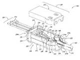
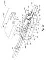
- FIGS. 2 A/ 2 Bare partially exploded isometric views of a furcated cable in accordance with several embodiments of the invention.
- FIG. 3is a top view of the furcated cable of FIG. 2 illustrating features of the furcated cable in more detail.
- FIG. 4is a partial top view of a portion of a furcation unit in accordance with an embodiment of the invention.
- FIG. 5is a partial top view of a portion of a furcation unit in accordance with another embodiment of the invention.
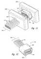
- FIG. 6is a partial isometric view of a furcation unit during a stage in an assembly process in accordance with another embodiment of the invention.
- FIG. 7is a partial isometric view of a furcation unit during a stage in an assembly process in accordance with another embodiment of the invention.
- FIG. 8is a partial isometric view of a furcation unit during a stage in an assembly process in accordance with another embodiment of the invention.
- FIG. 9is a partial isometric view of a furcation unit during a stage in an assembly process in accordance with another embodiment of the invention.
- FIG. 10is a partial isometric view of a furcation unit during a stage in an assembly process in accordance with another embodiment of the invention.
- FIG. 11is a partial isometric view of a furcation unit during a stage in an assembly process in accordance with another embodiment of the invention.
- FIG. 12is a partial isometric view of a furcation unit during a stage in an assembly process in accordance with another embodiment of the invention.
- FIG. 13is a partial isometric view of a furcation unit during a stage in an assembly process in accordance with another embodiment of the invention.
- FIG. 14is a partial isometric view of a furcation unit during a stage in an assembly process in accordance with another embodiment of the invention.
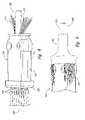
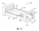
- FIG. 15is a partial isometric view of a furcation unit in accordance with a further embodiment of the invention.
- the present disclosuredescribes devices, assemblies, and methods for furcating a fiber optic cable.
- fiber opticmeans any strand capable of transmitting optic signals. Suitable fiber optic materials include optically transmissive glass or plastic threads. It will be appreciated that several of the details set forth below are provided to describe the following embodiments in a manner sufficient to enable a person skilled in the relevant art to make and use the disclosed embodiments. Several of the details and advantages described below, however, may not be necessary to practice certain embodiments of the invention. Additionally, the invention can include other embodiments that are within the scope of the claims but are not described in detail with respect to FIGS. 2-10 .
- a fiber optic cable assemblyincluding a housing having a first end, a second end, and an interior space between the two ends.
- the housinghas an opening at the first end and a plurality of channels at the second end.
- the fiber optic cable assemblyalso includes a plurality of furcation tubes aligned with corresponding channels and a bundled cable having cable filaments in a cable jacket.
- One end of the bundled cableextends into the interior space through the opening.
- the cable filamentsinclude a first portion extending beyond the end of the cable jacket in the interior space and a second portion extending through the opening to be external to the housing and/or the cable jacket.
- the fiber optic cable assemblyfurther includes a plurality of optic fibers movable to slide longitudinally relative to the bundled cable, the housing, and individual furcation tubes.
- a molding compoundis positioned around the furcation unit.
- a fiber optic cable assemblyincluding a furcation unit having a head with a plurality of channels, a base having an opening and an anchor, and a cover coupled to the base and the head to define an interior space.
- the fiber optic cable assemblyalso includes a bundled cable having cable filaments inside a cable jacket. A portion of the cable filaments extend beyond the cable jacket, around the anchor, and out of the interior space via the opening.
- the fiber optic cable assemblyfurther includes a plurality of furcation tubes corresponding to individual channels and a plurality of optic fibers slidably disposed in the bundled cable, the base, individual channels, and the furcation tubes.
- a fiber optic cable assemblyincluding a furcation unit having a first end, a second end, and an interior space.
- a bundled cable having a cable jacket and cable filamentsis disposed at the first end of the furcation unit.
- a molding compoundsecures the cable filaments to the furcation unit.
- the fiber optic cable assemblyalso includes a plurality of optic fibers extending through the bundled cable and the furcation unit to project from the second end of the furcation unit.
- the optic fibersare slidably movable in a longitudinal direction relative to the furcation unit and the bundled cable.
- a further aspectis directed toward a method of furcating a bundled cable into a plurality of furcation tubes.
- the bundled cablehas a cable jacket enclosing a plurality of optic fibers and cable filaments.
- the methodincludes removing the cable jacket to partially expose the optic fibers and cable filaments, disposing each of the optic fibers inside one of the furcation tubes by extending the optic fibers from the bundled cable through the furcation unit, and engaging the cable jacket to the furcation unit by disposing the cable filaments proximate to an anchor inside the furcation unit.
- FIG. 2Ais a partially exploded isometric view and FIG. 3 is a top view of a furcated cable 200 in accordance with an embodiment of the invention.
- the furcated cable 200can include a bundled cable 202 (e.g., a trunkline), furcation tubes 204 , and a furcation unit 206 in between the bundled cable 202 and the furcation tubes 204 .
- the furcated cable 200can further include a plurality of optic fibers 208 that are slidably disposed in the bundled cable 202 , the furcation unit 206 , and the furcation tubes 204 such that the optic fibers 208 can move in a longitudinal direction.
- the bundled cable 202can include a cable jacket 212 encasing cable filaments 210 and portions of the optic fibers 208 .
- the optic fibers 208 and the cable filaments 210can extend beyond one end of the cable jacket 212 proximate to the furcation unit 206 .
- the cable jacket 212can be constructed from plastic, metals, metal alloys, fiberglass, or other suitable materials.
- the cable filaments 210can include strength fibers constructed from Kevlar, Nylon, polyester, or other suitable materials.
- the optic fibers 208can include single-mode fibers, multi-mode fibers, index-graded fibers, or a combination of these types of optic fibers.
- the bundled cable 202can optionally include other components including, for example, insulating layers (e.g., a plastic sheath), strengthening devices to support the cable jacket 212 (e.g., metal rings or plastic strips), and signal transmission devices (e.g., waveguides, repeaters, etc.).
- insulating layerse.g., a plastic sheath
- strengthening devices to support the cable jacket 212e.g., metal rings or plastic strips
- signal transmission devicese.g., waveguides, repeaters, etc.
- Individual furcation tubes 204can include a tube jacket 214 , a buffer tube 218 slidably disposed inside the tube jacket 214 , and tube filaments 216 between the tube jacket 214 and the buffer tubes 218 .
- the tube filaments 216at least partially surround a corresponding buffer tube 218 .
- the buffer tube 218 and tube filaments 216can also extend beyond one end of the tube jacket 214 proximate to the furcation unit 206 .
- One optic fiber 208is inside one buffer tube 218 .
- the tube jackets 214 and buffer tubes 218can be constructed from plastic, metals, metal alloys, fiberglass, or other suitable materials.
- the tube filaments 216can include strength fibers constructed from Kevlar, nylon, polyester, or other suitable materials.
- the furcation unit 206can include a housing 207 or other enclosure having a head 220 , a base 222 , and a cover 224 that form an interior space 226 .
- the housing 207has a first end 209 a proximate to the bundled cable 202 and a second end 209 b proximate to the furcation tubes 204 .
- the head 220can be a generally rectangular structure having channels 228 configured to receive the buffer tubes 218 , a slot 221 configured to receive the base 222 and/or the cover 224 .
- the head 220can be constructed from plastic (e.g., polycarbonate, polyurethane, etc.), metal, wood, or other suitable materials. In other embodiments, the head 220 can be circular or another shape. Various embodiments of the head 220 are described in more detail below with reference to FIGS. 4 and 5 .
- the buffer tubes 218extend through the channels 228 and into the interior space 226 of the housing 207 .
- the buffer tubes 218can extend partially into the channels 228 but not into the interior space 226 .
- individual buffer tubes 218can encase one of the optic fibers 208 and be slidably disposed in the bundled cable 202 , the housing 207 , and one of the furcation tubes 204 .
- the buffer tubes 218can be omitted, and the optic fibers 208 extend through the channels 228 to be disposed inside the tube jackets 214 as shown in FIG. 2B .
- the cover 224can include features (e.g., channels, notches, holes, etc.) to correspond to the base 222 and the head 220 .
- the cover 224can be constructed from plastic, metal, wood, or other suitable materials.
- the cover 224cooperates with the base 222 to form an opening 238 for the cable jacket 212 at the first end 209 a of the housing 207 .
- the base 222 or the cover 224can include the opening 238 .
- the base 222can include a first end 230 proximate to the bundled cable 202 , a second end 232 proximate to the head 220 , a first side wall 234 , a second side wall 236 , and a bottom wall 237 extending between the first and second ends 230 , 232 .
- the first end 230can include the opening 238 for receiving the bundled cable 202 .
- the second end 232 of the base 222can be configured to correspond with the head 220 .
- the second end 232 of the base 222can include features including, channels, notches, holes, etc., for interfacing with the head 220 .
- the base 222can be constructed from plastic, metal, wood, or other suitable materials.
- the opening 238has a diameter larger than the outer diameter of the cable jacket 212 .
- the bundled cable 202can extend into the interior space 226 of the housing 207 through the opening 238 .
- the opening 238can have a diameter slightly smaller than the outer diameter of the cable jacket 212 such that the second end 232 stops the cable jacket 212 from extending into the interior space 226 of the furcation unit 206 .
- the base 222further includes a first anchor 240 and a second anchor 242 spaced apart from each other and near the first end 230 .
- the first and second anchors 240 , 242are formed integrally with the base 222 .
- the anchors 240 , 242are hollow columns with curved surfaces facing the second end 232 .
- the anchors 240 , 242can extend from the bottom wall 237 of the base 222 and have oval-shaped channels.
- the anchors 240 , 242can be solid structures fixedly attached to the bottom wall 237 of the base 222 .
- the first and second anchors 240 , 242can be generally cylindrical tubes fixedly attached to the bottom wall 237 of the base 222 using techniques including, for example, welding, friction fitting, mechanical fastening, etc.
- the first and second anchors 240 , 242can define a primary channel 244 between the inner facing walls of the anchors 240 , 242 .
- the first anchor 240 and the first side wall 234can define a first outer channel 246
- the second anchor 242 and the second side wall 236can define a second outer channel 248 .
- the optic fibers 208extend through the primary channel 244 to the buffer tubes 218 .
- the optic fibers 208are not fixed to the bundled cable 202 , the housing 207 , or the buffer tubes 218 , and thus the optic fibers 208 can slide longitudinally relative to these components.
- the cable filaments 210can include a first portion 210 a in the interior space and a second portion 210 b external to the housing 207 and/or the cable jacket 212 .
- the first portion 210 a of the cable filaments 210is positioned in the primary channel 244 and the first and second outer channels 246 , 248 to wrap around the faces of the first and second anchors 240 , 242 that face the second end 232 .
- the second portion 210 b of the cable filaments 210extends through the opening 238 to be external to the housing 207 and/or the cable jacket 212 .
- the cable filaments 210can be positioned in only one of the outer channels 246 , 248 .
- the furcated cable 200can further include at least one layer of molding (e.g., an epoxy 205 ) enclosing the furcation unit 206 .
- the epoxy 205can firmly attach the second portion 210 b of the cable filaments 210 to the furcation unit 206 and/or the cable jacket 212 .
- appropriate molding pressureis applied such that the epoxy 205 does not penetrate into the interior space 226 of the furcation unit 206 via the channels 228 and/or the opening 238 .
- the interior space 226 of the furcation unit 206is substantially free of the epoxy 205 or any other adhesives such that the optic fibers 208 can slide longitudinally relative to the cable bundle 202 and the furcation unit 206 .
- the epoxy 205can penetrate partially into the interior space 226 via the channels 218 and/or the opening 238 but not contact the optic fibers 208 .
- the optic fibers 208can slide longitudinally in the interior space 226 of the furcation unit 206 .
- One expected advantage of several embodiments of the furcated cable 200is the reduced risk of damaging the optic fibers 208 during handling processes because the furcation unit 206 can isolate tensile forces from the optic fibers 208 .
- the epoxy 205transmits the tension from the cable filaments 210 to the furcation unit 206 via the anchors 240 , 242 .
- the optic fibers 208are not fixed to the furcation unit 206 and can slide longitudinally inside the housing 207 relative to the cable jacket 212 , furcation tubes 204 , and the furcation unit 206 .
- the cable jacket 212 and the furcation unit 206bear substantially all of the tensile forces applied to the cable jacket 212 . Consequently, the risk of damaging the fragile optic fibers 208 can be reduced.
- Another expected advantage of several embodimentsis the ability to arrange a large number (e.g., 24) of furcation tubes in an organized fashion.
- the channels 228 at the head 220are organized into an array that has wiring designations (e.g., pin-out markings) to easily organize a large number of furcation tubes.
- the furcation unit 206can also reduce transmission loss through the furcated cable 200 .
- the optic fibers 208 of the furcated cable 200are continuous, i.e., not spliced in the furcation unit 206 .
- the furcation unit 206does not incur any appreciable insertion loss caused by splices.
- the furcated cable 200can have many additional embodiments with different and/or additional features without detracting from the operation of the furcated cable 200 .
- the head 220 , the base 222 , and/or the cover 224 of the furcation unit 206can be formed as a unitary structure before assembly.
- the furcated cable 200can include a heat-shrink tube covering the cable filaments 210 external to the cable jacket 212 before the epoxy 205 is applied.
- the furcated cable 200can also include an adhesive between the furcation tubes 204 and the head 220 for additional structural integrity.
- the furcated cable 200can include fasteners including, for example, mechanical fasteners, compression fittings, etc., to assemble the furcation unit 206 , the bundled cable 202 , and the furcation tubes 204 into a furcated cable.
- FIG. 4is a partial top view of the furcation unit 206 of FIGS. 2 and 3 illustrating the head 220 in more detail.
- the channels 228can extend from a first face 215 to a second face 217 of the head 220 .
- the channels 228can have a diameter larger than the outer diameter of the buffer tube 218 but smaller than the inner diameter of the tube jacket 214 .
- the buffer tubes 218extend through the channels 228 , but the tube jackets 214 and the tube filaments 216 butt up against the first face 215 .
- the tube jacket 214 and the tube filaments 216therefore, do not pass into the interior space 226 .
- the epoxy 205can firmly attach the tube filaments 216 to the tube jacket 214 and/or the furcation unit 206 .
- FIG. 5is an alternative example of the furcation unit 206 of FIG. 4 in accordance with one embodiment of the invention.
- This alternative example and other alternatives described hereinare substantially similar to previously described examples, and common acts and structures are identified by the same reference numbers. Only significant differences in operation and structure are described below.
- the furcation unit 206includes a head 300 having first channels 302 and second channels 304 .
- a first channel 302corresponds to and is in communication with a second channel 304 .
- the first channel 302can have a diameter larger than the outer diameter of the tube jacket 214 .
- the second channel 304can have a diameter smaller than the inner diameter of the tube jacket 214 but larger than the outer diameter of the buffer tube 218 .
- the tube jacket 214 and a portion of the tube filaments 216can at least partially extend into the first channel 302 but not pass through the second channel 304 . Instead, only the buffer tube 218 extends through the second channel 304 and into the interior space 226 .
- the head 300includes an adhesive disposed in the first channels 302 to firmly engage the tube jacket 214 to the head 300 .
- the furcation tube 204can engage the head 300 by friction, mechanical fastening, or other suitable means.
- FIGS. 6-9are partial isometric views of a furcation unit during stages in an assembly process in accordance with one embodiment of the invention.
- a portion of the tube jacket 214can be removed from each of the furcation tubes 204 to expose a desired length (e.g., two inches) of the buffer tube 218 and the tube filaments 216 .
- the exposed buffer tube 218can then be inserted through one of the channels 228 at the head 220 of the furcation unit 206 .
- each channel 228receives one buffer tube 218 and prevents the exposed tube filaments 216 and the tube jackets 214 from extending through the channels 228 .
- a portion of the cable jacket 212can be removed to expose a desired length of the optic fibers 208 and the cable filaments 210 .
- each of the optic fibers 208is inserted in one of the corresponding buffer tubes 218 extending from the head 220 via the primary channel 244 and the internal space 226 of the furcation unit 206 .
- a first portion 211 of the exposed cable filaments 210can be wrapped around the first anchor 240 and extended beyond the opening 238 to be external to the cable jacket 212 .
- a second portion 213 of the exposed cable filaments 210can be wrapped around the second anchor 242 and extended beyond the opening 238 to be external to the cable jacket 212 .
- the cable filaments 210 external to the cable jacket 212can be at least partially aligned with the bundled cable 202 . Then the base 222 can be inserted into the head 220 . The cover portion can then be combined with the head 220 and the base 222 to form the furcation unit 206 as illustrated in FIG. 8 .
- a heat-shrink tube 252can be disposed at least partially over the furcation unit 206 and the bundled cable 202 .
- the heat-shrink tube 252can at least partially fasten the cable filaments 210 to the cable jacket 212 before heat molding.
- a portion of the cable filaments 210extends from the heat-shrink tube 252 to cover a portion of the furcation unit 206 .
- the heat-shrink tube 252can substantially completely cover the cable filaments 210 external to the cable jacket 212 .
- the epoxy 205can then be disposed over the furcation unit 206 and at least a portion of the bundled cable 202 and the furcation tubes 204 .
- at least one layer of epoxy 205can be disposed.
- other means of assemblycan be used including, for example, mechanical fasteners, compression fittings, etc.
- FIGS. 10-14are partial isometric views of a furcation unit during stages in an alternative assembly process in accordance with another embodiment of the invention.
- a first template 223 acan be placed adjacent to the head 220 .
- the first template 223 ais a generally rectangular block having apertures (not shown) corresponding to the channels 228 to allow the buffer tubes 218 to extend through.
- the first template 223 acan be constructed from plastic, metal, wood, or any suitable material with sufficient rigidity.
- the buffer tubes 218can be partially exposed from the tube jackets 214 and inserted through the channels 228 at the head 220 of the furcation unit 206 .
- a second template 223 b similar to the first template 223 acan then be placed spaced apart from the head 220 .
- the second template 223 bincludes apertures 229 to allow the tube jackets 214 to extend through the second template 223 b .
- a molding compound 225e.g., an epoxy
- a molding compound 225can be disposed between the first and second templates 223 a - b to fasten the tube jackets 214 but not the buffer tubes 218 to the head 220 .
- a portion of the molding compound 225is removed for clarity.
- the buffer tubes 218are withdrawn from the tube jackets 214 , and the first and second templates 223 a - b are removed to form a subassembly 201 as illustrated in FIG. 12 .
- a portion of the cable jacket 212can be removed to expose a desired length of the optic fibers 208 and the cable filaments 210 .
- each of the optic fibers 208is inserted in one of the channels 228 via the primary channel 244 and the internal space 226 of the furcation unit 206 .
- a first portion 211 of the exposed cable filaments 210can be wrapped around the first anchor 240 and extended beyond the opening 238 to be external to the cable jacket 212 .
- a second portion 213 of the exposed cable filaments 210can be wrapped around the second anchor 242 and extended beyond the opening 238 to be external to the cable jacket 212 .
- the cable filaments 210 external to the cable jacket 212can be at least partially aligned with the bundled cable 202 .
- the base 222can be inserted into the subassembly 201 .
- the cover portioncan then be combined with the subassembly 201 and the base 222 to form the furcation unit 206 as illustrated in FIG. 14 .
- the heat-shrink tube 252can be disposed at least partially over the furcation unit 206 and the bundled cable 202 as described above with reference to FIG. 9 .
- the epoxy 205can then be disposed over the furcation unit 206 , the subassembly 201 , at least a portion of the bundled cable 202 and the furcation tubes 204 .
- FIG. 15is an alternative example of the furcation unit 206 of FIG. 4 in accordance with another embodiment of the invention.
- the cover 224has been removed for clarity.
- the base 222includes a cable seat 402 positioned proximate to the opening 238 and configured to support the bundled cable 202 ( FIG. 2 ).
- the base 222further includes an anchor 404 proximate to the opening 238 .
- the anchor 404can have a generally elongated shape and be spaced apart from the first side wall 234 to define a primary channel 406 .
- the second side wall 236 and the cable seat 402can define a secondary channel 408 .
- the cable filaments 210can pass through the channels 406 , 408 and extend beyond the opening 238 to be external to the furcation unit 206 .
- the furcation unit 206can further include an end portion 410 opposite the head 220 .
- the end portion 410can be either releasably or fixedly attached to the base 222 .
- the end portion 410can be constructed from plastic, metals, metal alloys, fiberglass, or other suitable materials.
- the end portion 410includes a generally rectangular structure having a hollow center for receiving the second end 232 of the base 222 .
- the end portion 410can include other shapes and/or configurations including, for example, a ring-shaped structure, a square-shaped structure, etc.
Landscapes
- Physics & Mathematics (AREA)
- General Physics & Mathematics (AREA)
- Optics & Photonics (AREA)
- Details Of Indoor Wiring (AREA)
Abstract
Description
Claims (39)
Priority Applications (3)
| Application Number | Priority Date | Filing Date | Title |
|---|---|---|---|
| US11/474,110US7270485B1 (en) | 2006-06-23 | 2006-06-23 | Device for furcating fiber optic cables |
| US11/838,683US7494284B2 (en) | 2006-06-23 | 2007-08-14 | Device for furcating fiber optic cables |
| US12/364,456US20090190889A1 (en) | 2006-06-23 | 2009-02-02 | Device for furcating fiber optic cables |
Applications Claiming Priority (1)
| Application Number | Priority Date | Filing Date | Title |
|---|---|---|---|
| US11/474,110US7270485B1 (en) | 2006-06-23 | 2006-06-23 | Device for furcating fiber optic cables |
Related Child Applications (1)
| Application Number | Title | Priority Date | Filing Date |
|---|---|---|---|
| US11/838,683ContinuationUS7494284B2 (en) | 2006-06-23 | 2007-08-14 | Device for furcating fiber optic cables |
Publications (1)
| Publication Number | Publication Date |
|---|---|
| US7270485B1true US7270485B1 (en) | 2007-09-18 |
Family
ID=38481715
Family Applications (3)
| Application Number | Title | Priority Date | Filing Date |
|---|---|---|---|
| US11/474,110ActiveUS7270485B1 (en) | 2006-06-23 | 2006-06-23 | Device for furcating fiber optic cables |
| US11/838,683ActiveUS7494284B2 (en) | 2006-06-23 | 2007-08-14 | Device for furcating fiber optic cables |
| US12/364,456AbandonedUS20090190889A1 (en) | 2006-06-23 | 2009-02-02 | Device for furcating fiber optic cables |
Family Applications After (2)
| Application Number | Title | Priority Date | Filing Date |
|---|---|---|---|
| US11/838,683ActiveUS7494284B2 (en) | 2006-06-23 | 2007-08-14 | Device for furcating fiber optic cables |
| US12/364,456AbandonedUS20090190889A1 (en) | 2006-06-23 | 2009-02-02 | Device for furcating fiber optic cables |
Country Status (1)
| Country | Link |
|---|---|
| US (3) | US7270485B1 (en) |
Cited By (92)
| Publication number | Priority date | Publication date | Assignee | Title |
|---|---|---|---|---|
| US20090058666A1 (en)* | 2007-09-05 | 2009-03-05 | Chris Clabaugh | Tank fluid level monitor and indicator |
| US20090196563A1 (en)* | 2008-02-01 | 2009-08-06 | Mullsteff David M | Multi-Fiber Optical Patch Cord Breakout Assembly |
| US20090264021A1 (en)* | 2008-04-18 | 2009-10-22 | Phoenix Contact Gmbh & Co. Kg | Connection device |
| WO2009150011A1 (en)* | 2008-06-10 | 2009-12-17 | Tyco Electronics Nederland Bv | Fiber optic furcation assembly |
| US20090310928A1 (en)* | 2008-06-12 | 2009-12-17 | Wolf Kluwe | Universal cable bracket |
| EP2148231A1 (en)* | 2008-07-25 | 2010-01-27 | CCS Technology, Inc. | Furcation adapter |
| US20100054688A1 (en)* | 2008-09-03 | 2010-03-04 | Julian Mullaney | Cable strain relief clamping devices and methods for using the same |
| US20100054689A1 (en)* | 2008-09-03 | 2010-03-04 | Julian Mullaney | Cable Clamping Devices and Methods for Using the Same |
| US20100067855A1 (en)* | 2008-09-12 | 2010-03-18 | Draka Comteq B.V. | Buffer Tubes for Mid-Span Storage |
| US20100092135A1 (en)* | 2008-09-12 | 2010-04-15 | Draka Comteq B.V. | Optical Fiber Cable Assembly |
| US20100092136A1 (en)* | 2008-10-06 | 2010-04-15 | Ponharith Nhep | Fanout cable assembly and method |
| US20100098386A1 (en)* | 2008-10-17 | 2010-04-22 | Kleeberger Terry M | Devices and associated methods for furcating fiber optic cables |
| US7703990B1 (en) | 2009-04-23 | 2010-04-27 | Corning Cable Systems Llc | Furcation bodies and fiber optic assemblies using the same |
| US20100129041A1 (en)* | 2008-11-25 | 2010-05-27 | Fujitsu Limited | Attachment part and electronic apparatus |
| GB2472014A (en)* | 2009-07-20 | 2011-01-26 | Fibrefab Ltd | Connector device and method for producing a furcated fibre optic cable |
| US20110038589A1 (en)* | 2009-08-13 | 2011-02-17 | Gil Ruiz | Fiber management component |
| US20110317975A1 (en)* | 2010-06-25 | 2011-12-29 | Adc Telecommunications, Inc. | Transition housing and cap for fiber breakout assembly |
| US20130022328A1 (en)* | 2007-03-23 | 2013-01-24 | Adc Telecommunications, Inc. | Drop Terminal with Anchor Block for Retaining a Stub Cable |
| US8410909B2 (en) | 2010-07-09 | 2013-04-02 | Corning Incorporated | Cables and connector assemblies employing a furcation tube(s) for radio-frequency identification (RFID)-equipped connectors, and related systems and methods |
| US8433171B2 (en) | 2009-06-19 | 2013-04-30 | Corning Cable Systems Llc | High fiber optic cable packing density apparatus |
| US8457461B2 (en) | 2010-04-16 | 2013-06-04 | Adc Telecommunications, Inc. | Fiber optic cable assembly and method of making the same |
| US20130233615A1 (en)* | 2010-11-29 | 2013-09-12 | 3M Innovative Properties Company | Strain relief device |
| US20130233612A1 (en)* | 2010-11-29 | 2013-09-12 | 3M Innovative Properties Company | Strain relief device |
| US8538226B2 (en) | 2009-05-21 | 2013-09-17 | Corning Cable Systems Llc | Fiber optic equipment guides and rails configured with stopping position(s), and related equipment and methods |
| US8542973B2 (en) | 2010-04-23 | 2013-09-24 | Ccs Technology, Inc. | Fiber optic distribution device |
| US8593828B2 (en) | 2010-02-04 | 2013-11-26 | Corning Cable Systems Llc | Communications equipment housings, assemblies, and related alignment features and methods |
| US8625944B1 (en) | 2009-05-13 | 2014-01-07 | Draka Comteq, B.V. | Low-shrink reduced-diameter buffer tubes |
| US8625950B2 (en) | 2009-12-18 | 2014-01-07 | Corning Cable Systems Llc | Rotary locking apparatus for fiber optic equipment trays and related methods |
| US8625945B1 (en) | 2009-05-13 | 2014-01-07 | Draka Comteq, B.V. | Low-shrink reduced-diameter dry buffer tubes |
| US8660397B2 (en) | 2010-04-30 | 2014-02-25 | Corning Cable Systems Llc | Multi-layer module |
| US8662760B2 (en) | 2010-10-29 | 2014-03-04 | Corning Cable Systems Llc | Fiber optic connector employing optical fiber guide member |
| US8699838B2 (en) | 2009-05-14 | 2014-04-15 | Ccs Technology, Inc. | Fiber optic furcation module |
| US8705926B2 (en) | 2010-04-30 | 2014-04-22 | Corning Optical Communications LLC | Fiber optic housings having a removable top, and related components and methods |
| US8712206B2 (en) | 2009-06-19 | 2014-04-29 | Corning Cable Systems Llc | High-density fiber optic modules and module housings and related equipment |
| US8718436B2 (en) | 2010-08-30 | 2014-05-06 | Corning Cable Systems Llc | Methods, apparatuses for providing secure fiber optic connections |
| US20140140664A1 (en)* | 2012-11-19 | 2014-05-22 | Andrew Llc | Optical fiber / electrical composite cable assembly with sealed breakout kit |
| US20140193130A1 (en)* | 2013-01-09 | 2014-07-10 | Tyco Electronics Corporation | Fan-out subassembly |
| US8818156B2 (en) | 2010-03-30 | 2014-08-26 | Corning Cable Systems Llc | Multiple channel optical fiber furcation tube and cable assembly using same |
| US8879881B2 (en) | 2010-04-30 | 2014-11-04 | Corning Cable Systems Llc | Rotatable routing guide and assembly |
| US8890050B2 (en) | 2011-11-21 | 2014-11-18 | Tyco Electronics Corporation | Photosensor circuits including a regulated power supply comprising a power circuit configured to provide a regulated power signal to a comparator of a pulse-width modulator |
| US8913866B2 (en) | 2010-03-26 | 2014-12-16 | Corning Cable Systems Llc | Movable adapter panel |
| WO2014200999A1 (en)* | 2013-06-10 | 2014-12-18 | Afl Telecommunications Llc | Optical fiber furcation assembly and method |
| US20150010282A1 (en)* | 2013-07-04 | 2015-01-08 | Sumitomo Electric Industries, Ltd. | Optical module |
| US8953924B2 (en) | 2011-09-02 | 2015-02-10 | Corning Cable Systems Llc | Removable strain relief brackets for securing fiber optic cables and/or optical fibers to fiber optic equipment, and related assemblies and methods |
| US8958673B2 (en) | 2011-05-27 | 2015-02-17 | Corning Cable Systems Llc | Molded fiber optic cable furcation assemblies, and related fiber optic components, assemblies, and methods |
| US8989547B2 (en) | 2011-06-30 | 2015-03-24 | Corning Cable Systems Llc | Fiber optic equipment assemblies employing non-U-width-sized housings and related methods |
| US8985862B2 (en) | 2013-02-28 | 2015-03-24 | Corning Cable Systems Llc | High-density multi-fiber adapter housings |
| US8995812B2 (en) | 2012-10-26 | 2015-03-31 | Ccs Technology, Inc. | Fiber optic management unit and fiber optic distribution device |
| US9008485B2 (en) | 2011-05-09 | 2015-04-14 | Corning Cable Systems Llc | Attachment mechanisms employed to attach a rear housing section to a fiber optic housing, and related assemblies and methods |
| US9020320B2 (en) | 2008-08-29 | 2015-04-28 | Corning Cable Systems Llc | High density and bandwidth fiber optic apparatuses and related equipment and methods |
| US9022814B2 (en) | 2010-04-16 | 2015-05-05 | Ccs Technology, Inc. | Sealing and strain relief device for data cables |
| US9042702B2 (en) | 2012-09-18 | 2015-05-26 | Corning Cable Systems Llc | Platforms and systems for fiber optic cable attachment |
| US9038832B2 (en) | 2011-11-30 | 2015-05-26 | Corning Cable Systems Llc | Adapter panel support assembly |
| US9059578B2 (en) | 2009-02-24 | 2015-06-16 | Ccs Technology, Inc. | Holding device for a cable or an assembly for use with a cable |
| US9075217B2 (en) | 2010-04-30 | 2015-07-07 | Corning Cable Systems Llc | Apparatuses and related components and methods for expanding capacity of fiber optic housings |
| US9075216B2 (en) | 2009-05-21 | 2015-07-07 | Corning Cable Systems Llc | Fiber optic housings configured to accommodate fiber optic modules/cassettes and fiber optic panels, and related components and methods |
| US9116324B2 (en) | 2010-10-29 | 2015-08-25 | Corning Cable Systems Llc | Stacked fiber optic modules and fiber optic equipment configured to support stacked fiber optic modules |
| US9140872B2 (en) | 2013-09-17 | 2015-09-22 | Panduit Corp. | Hydra cable assembly and components thereof |
| US20150349453A1 (en)* | 2014-04-15 | 2015-12-03 | Nexans | Device for dividing a bundle of insulated electrical conductors |
| US9213161B2 (en) | 2010-11-05 | 2015-12-15 | Corning Cable Systems Llc | Fiber body holder and strain relief device |
| US9250409B2 (en) | 2012-07-02 | 2016-02-02 | Corning Cable Systems Llc | Fiber-optic-module trays and drawers for fiber-optic equipment |
| US9279951B2 (en) | 2010-10-27 | 2016-03-08 | Corning Cable Systems Llc | Fiber optic module for limited space applications having a partially sealed module sub-assembly |
| EP3001231A1 (en)* | 2014-09-26 | 2016-03-30 | CCS Technology, Inc. | Apparatus and method for inserting optical fibers into tubes |
| US9500830B2 (en) | 2012-09-28 | 2016-11-22 | Commscope Technologies Llc | Splice-on cable breakout assembly |
| US9519118B2 (en) | 2010-04-30 | 2016-12-13 | Corning Optical Communications LLC | Removable fiber management sections for fiber optic housings, and related components and methods |
| US20170045550A1 (en)* | 2015-08-11 | 2017-02-16 | Tektronix, Inc. | Cable Assembly With Spine For Instrument Probe |
| US9575277B2 (en)* | 2015-01-15 | 2017-02-21 | Raycap, S.A. | Fiber optic cable breakout assembly |
| US20170082818A1 (en)* | 2014-06-12 | 2017-03-23 | Commscope Technologies Llc | Environmental sealing arrangement for furcated optical fibers |
| US9632270B2 (en) | 2010-04-30 | 2017-04-25 | Corning Optical Communications LLC | Fiber optic housings configured for tool-less assembly, and related components and methods |
| US9640986B2 (en) | 2013-10-23 | 2017-05-02 | Raycap Intellectual Property Ltd. | Cable breakout assembly |
| US9645317B2 (en) | 2011-02-02 | 2017-05-09 | Corning Optical Communications LLC | Optical backplane extension modules, and related assemblies suitable for establishing optical connections to information processing modules disposed in equipment racks |
| US9720195B2 (en) | 2010-04-30 | 2017-08-01 | Corning Optical Communications LLC | Apparatuses and related components and methods for attachment and release of fiber optic housings to and from an equipment rack |
| US20180196211A1 (en)* | 2017-01-10 | 2018-07-12 | Fujikura Ltd. | Optical fiber cord and method of manufacturing optical fiber cord |
| US10094996B2 (en) | 2008-08-29 | 2018-10-09 | Corning Optical Communications, Llc | Independently translatable modules and fiber optic equipment trays in fiber optic equipment |
| US20190004273A1 (en)* | 2017-06-28 | 2019-01-03 | Corning Research & Development Corporation | High fiber count pre-terminated optical distribution assembly |
| US10175430B2 (en) | 2016-05-05 | 2019-01-08 | Belden Canada Inc. | Overmoulded furcation assembly with strain relief |
| US10181717B2 (en) | 2010-07-13 | 2019-01-15 | Raycap S.A. | Overvoltage protection system for wireless communication systems |
| USD847091S1 (en) | 2016-11-11 | 2019-04-30 | Afl Ig Llc | Housing for cable transition assembly |
| US10353164B2 (en) | 2017-06-27 | 2019-07-16 | Afl Telecommunications Llc | Fiber optic transition assemblies |
| US10444461B1 (en) | 2015-08-31 | 2019-10-15 | Afl Ig Llc | Methods, systems and apparatus for manufacturing a cable assembly with breakout and molded cable assembly |
| US20190384016A1 (en)* | 2017-02-28 | 2019-12-19 | Huawei Technologies Co., Ltd. | Fiber access terminal |
| US10514520B2 (en) | 2014-10-27 | 2019-12-24 | Commscope Technologies Llc | Fiber optic cable with flexible conduit |
| US10606019B2 (en) | 2015-07-31 | 2020-03-31 | Commscope Technologies Australia Pty Ltd | Cable breakout assembly |
| US10890730B2 (en) | 2016-08-31 | 2021-01-12 | Commscope Technologies Llc | Fiber optic cable clamp and clamp assembly |
| US10914909B2 (en) | 2016-10-13 | 2021-02-09 | Commscope Technologies Llc | Fiber optic breakout transition assembly incorporating epoxy plug and cable strain relief |
| US11131821B2 (en) | 2016-03-18 | 2021-09-28 | Commscope Technologies Llc | Optic fiber cable fanout conduit arrangements; components, and methods |
| US11131822B2 (en) | 2017-05-08 | 2021-09-28 | Commscope Technologies Llc | Fiber-optic breakout transition assembly |
| US11226464B2 (en)* | 2019-03-07 | 2022-01-18 | Commscope Technologies Llc | Telecommunications fan-out arrangement |
| DE102020123878A1 (en) | 2020-09-14 | 2022-03-17 | Berthold Sichert Gmbh | Feeder for optical fiber microcables, cable distribution cabinet with such a feeder, method of feeding optical fiber microcables |
| US11294135B2 (en) | 2008-08-29 | 2022-04-05 | Corning Optical Communications LLC | High density and bandwidth fiber optic apparatuses and related equipment and methods |
| US11340409B1 (en)* | 2020-12-31 | 2022-05-24 | Huizhou Fibercan Industrial Co., Ltd. | GH splitter |
| US20220229253A1 (en)* | 2019-04-17 | 2022-07-21 | Commscope Technologies Llc | Telecommunications cable guide |
Families Citing this family (11)
| Publication number | Priority date | Publication date | Assignee | Title |
|---|---|---|---|---|
| US7955004B2 (en)* | 2008-09-04 | 2011-06-07 | Fibersource, Inc. | Fiber optic furcation method |
| US8371015B2 (en)* | 2009-09-24 | 2013-02-12 | Bright Technologies, Llc | Method of terminating a stranded synthetic filament cable |
| WO2012038104A1 (en)* | 2010-09-21 | 2012-03-29 | Huber+Suhner Ag | Environmentally sealed cable breakout assemblies |
| US20130183012A1 (en)* | 2012-01-13 | 2013-07-18 | Alma Delia Cabanne Lopez | Fan-out kit for a furcation system |
| WO2014071021A1 (en)* | 2012-10-31 | 2014-05-08 | Adc Telecommunications, Inc. | Anchoring cables to rack with cable clamp arrangements |
| US10156692B2 (en)* | 2014-06-17 | 2018-12-18 | Afl Telecommunications Llc | Optical fiber furcation transition assembly with integrated retention feature |
| WO2016069514A1 (en)* | 2014-10-27 | 2016-05-06 | Netig, Llc | Apparatus and methods for furcating fiber optic cables |
| CN105676380B (en)* | 2014-11-21 | 2019-07-12 | 泰科电子(上海)有限公司 | Cable runs system and multifibre joint |
| US10247899B2 (en)* | 2015-09-04 | 2019-04-02 | Commscope Technologies Llc | Device for distributing hybrid trunk cable |
| US10330881B1 (en) | 2017-12-21 | 2019-06-25 | Afl Telecommunications Llc | Optical fiber furcation assemblies |
| EP3830622A4 (en)* | 2018-08-01 | 2022-05-04 | CommScope Technologies LLC | OUTPUT BRANCH DISTRIBUTION BOX WITH ISOLATED FIBER CHAMBER |
Citations (16)
| Publication number | Priority date | Publication date | Assignee | Title |
|---|---|---|---|---|
| US4826277A (en) | 1987-10-30 | 1989-05-02 | Amp Incorporated | Transition of a multiple fiber cable to single fiber cable |
| US4884862A (en) | 1988-10-17 | 1989-12-05 | Minnesota Mining And Manufacturing Company | Fiber optic fan-out module |
| US4989945A (en) | 1989-04-14 | 1991-02-05 | Sumitomo Electric Industries, Ltd. | Branch device for multi-core optical fiber |
| US5048918A (en) | 1990-02-07 | 1991-09-17 | Raychem Corporation | Optical fiber cable termination |
| US5231688A (en)* | 1991-10-07 | 1993-07-27 | Siecor Corporation | Furcation kit |
| US5239609A (en) | 1992-03-03 | 1993-08-24 | Porta Systems Corp. | Means for routing buffer tube type fiber optical cable |
| US5335304A (en) | 1993-04-30 | 1994-08-02 | The United States Of America As Represented By The Secretary Of The Army | Connector distribution assembly for a fiber optic detector system |
| US5473718A (en)* | 1994-09-20 | 1995-12-05 | The United States Of America As Represented By The Secretary Of The Navy | Fiber optic loose tube buffer to fan-out tube adapter system |
| US5838861A (en) | 1997-03-06 | 1998-11-17 | Newport News Shipbuilding And Dry Dock Company | Transition assembly for optical fiber |
| US5903693A (en) | 1997-09-30 | 1999-05-11 | The United States Of America As Represented By The Secretary Of The Navy | Fiber optic cable furcation unit |
| US5915055A (en)* | 1997-06-30 | 1999-06-22 | Siecor Corporation | Method and apparatus for connectorizing fiber optic cable |
| US6278831B1 (en)* | 1999-01-08 | 2001-08-21 | Priority Electronics Inc. | Fiber optic cable assembly |
| US6389214B1 (en)* | 2001-05-17 | 2002-05-14 | 3M Innovative Properties Company | Furcation apparatus for optical fibers |
| US20030147604A1 (en) | 2002-02-01 | 2003-08-07 | Tapia Alejandro L. | Housing assembly for providing combined electrical grounding and fiber distribution of a fiber optic cable |
| US20050053341A1 (en)* | 2003-09-08 | 2005-03-10 | Zimmel Steven C. | Fiber optic cable and furcation module |
| US7054536B2 (en) | 2004-05-12 | 2006-05-30 | Molex Incorporated | Breakout assembly for flexible circuitry |
Family Cites Families (1)
| Publication number | Priority date | Publication date | Assignee | Title |
|---|---|---|---|---|
| US7093984B2 (en)* | 2003-11-06 | 2006-08-22 | 3M Innovative Properties Company | Anchor for fiber optic cable |
- 2006
- 2006-06-23USUS11/474,110patent/US7270485B1/enactiveActive
- 2007
- 2007-08-14USUS11/838,683patent/US7494284B2/enactiveActive
- 2009
- 2009-02-02USUS12/364,456patent/US20090190889A1/ennot_activeAbandoned
Patent Citations (16)
| Publication number | Priority date | Publication date | Assignee | Title |
|---|---|---|---|---|
| US4826277A (en) | 1987-10-30 | 1989-05-02 | Amp Incorporated | Transition of a multiple fiber cable to single fiber cable |
| US4884862A (en) | 1988-10-17 | 1989-12-05 | Minnesota Mining And Manufacturing Company | Fiber optic fan-out module |
| US4989945A (en) | 1989-04-14 | 1991-02-05 | Sumitomo Electric Industries, Ltd. | Branch device for multi-core optical fiber |
| US5048918A (en) | 1990-02-07 | 1991-09-17 | Raychem Corporation | Optical fiber cable termination |
| US5231688A (en)* | 1991-10-07 | 1993-07-27 | Siecor Corporation | Furcation kit |
| US5239609A (en) | 1992-03-03 | 1993-08-24 | Porta Systems Corp. | Means for routing buffer tube type fiber optical cable |
| US5335304A (en) | 1993-04-30 | 1994-08-02 | The United States Of America As Represented By The Secretary Of The Army | Connector distribution assembly for a fiber optic detector system |
| US5473718A (en)* | 1994-09-20 | 1995-12-05 | The United States Of America As Represented By The Secretary Of The Navy | Fiber optic loose tube buffer to fan-out tube adapter system |
| US5838861A (en) | 1997-03-06 | 1998-11-17 | Newport News Shipbuilding And Dry Dock Company | Transition assembly for optical fiber |
| US5915055A (en)* | 1997-06-30 | 1999-06-22 | Siecor Corporation | Method and apparatus for connectorizing fiber optic cable |
| US5903693A (en) | 1997-09-30 | 1999-05-11 | The United States Of America As Represented By The Secretary Of The Navy | Fiber optic cable furcation unit |
| US6278831B1 (en)* | 1999-01-08 | 2001-08-21 | Priority Electronics Inc. | Fiber optic cable assembly |
| US6389214B1 (en)* | 2001-05-17 | 2002-05-14 | 3M Innovative Properties Company | Furcation apparatus for optical fibers |
| US20030147604A1 (en) | 2002-02-01 | 2003-08-07 | Tapia Alejandro L. | Housing assembly for providing combined electrical grounding and fiber distribution of a fiber optic cable |
| US20050053341A1 (en)* | 2003-09-08 | 2005-03-10 | Zimmel Steven C. | Fiber optic cable and furcation module |
| US7054536B2 (en) | 2004-05-12 | 2006-05-30 | Molex Incorporated | Breakout assembly for flexible circuitry |
Non-Patent Citations (1)
| Title |
|---|
| "Pre-Terminated Multi-Fiber Cables," Berk-Tek product brochure, accessed Feb. 7, 2006. |
Cited By (162)
| Publication number | Priority date | Publication date | Assignee | Title |
|---|---|---|---|---|
| US20130022328A1 (en)* | 2007-03-23 | 2013-01-24 | Adc Telecommunications, Inc. | Drop Terminal with Anchor Block for Retaining a Stub Cable |
| US8179272B2 (en)* | 2007-09-05 | 2012-05-15 | Chris Clabaugh | Tank fluid level monitor and refill indicator |
| US20090058666A1 (en)* | 2007-09-05 | 2009-03-05 | Chris Clabaugh | Tank fluid level monitor and indicator |
| US20090196563A1 (en)* | 2008-02-01 | 2009-08-06 | Mullsteff David M | Multi-Fiber Optical Patch Cord Breakout Assembly |
| DE102008019758B3 (en)* | 2008-04-18 | 2010-01-28 | Phoenix Contact Gmbh & Co. Kg | connection device |
| US20090264021A1 (en)* | 2008-04-18 | 2009-10-22 | Phoenix Contact Gmbh & Co. Kg | Connection device |
| US7824108B2 (en) | 2008-04-18 | 2010-11-02 | Phoenix Contact Gmbh & Co. Kg | Connection device with conductor length compensation |
| US8571367B2 (en) | 2008-06-10 | 2013-10-29 | Tyco Electronics Nederland Bv | Fiber optic furcation assembly |
| WO2009150011A1 (en)* | 2008-06-10 | 2009-12-17 | Tyco Electronics Nederland Bv | Fiber optic furcation assembly |
| CN102057310B (en)* | 2008-06-10 | 2014-11-19 | 泰科电子荷兰公司 | Fiber Fusion Components |
| JP2011523101A (en)* | 2008-06-10 | 2011-08-04 | タイコ エレクトロニクス ネーデルランド ビーヴイ | Optical fiber branch assembly |
| US20110091169A1 (en)* | 2008-06-10 | 2011-04-21 | Tyco Electronics Nederland Bv | Fiber optic furcation assembly |
| US7787740B2 (en)* | 2008-06-12 | 2010-08-31 | Corning Cable Systems Llc | Universal cable bracket |
| US20090310928A1 (en)* | 2008-06-12 | 2009-12-17 | Wolf Kluwe | Universal cable bracket |
| EP2148231A1 (en)* | 2008-07-25 | 2010-01-27 | CCS Technology, Inc. | Furcation adapter |
| US9910236B2 (en) | 2008-08-29 | 2018-03-06 | Corning Optical Communications LLC | High density and bandwidth fiber optic apparatuses and related equipment and methods |
| US10126514B2 (en) | 2008-08-29 | 2018-11-13 | Corning Optical Communications, Llc | Independently translatable modules and fiber optic equipment trays in fiber optic equipment |
| US10422971B2 (en) | 2008-08-29 | 2019-09-24 | Corning Optical Communicatinos LLC | High density and bandwidth fiber optic apparatuses and related equipment and methods |
| US10416405B2 (en) | 2008-08-29 | 2019-09-17 | Corning Optical Communications LLC | Independently translatable modules and fiber optic equipment trays in fiber optic equipment |
| US10444456B2 (en) | 2008-08-29 | 2019-10-15 | Corning Optical Communications LLC | High density and bandwidth fiber optic apparatuses and related equipment and methods |
| US10459184B2 (en) | 2008-08-29 | 2019-10-29 | Corning Optical Communications LLC | High density and bandwidth fiber optic apparatuses and related equipment and methods |
| US9020320B2 (en) | 2008-08-29 | 2015-04-28 | Corning Cable Systems Llc | High density and bandwidth fiber optic apparatuses and related equipment and methods |
| US10222570B2 (en) | 2008-08-29 | 2019-03-05 | Corning Optical Communications LLC | Independently translatable modules and fiber optic equipment trays in fiber optic equipment |
| US10564378B2 (en) | 2008-08-29 | 2020-02-18 | Corning Optical Communications LLC | High density and bandwidth fiber optic apparatuses and related equipment and methods |
| US11609396B2 (en) | 2008-08-29 | 2023-03-21 | Corning Optical Communications LLC | High density and bandwidth fiber optic apparatuses and related equipment and methods |
| US10606014B2 (en) | 2008-08-29 | 2020-03-31 | Corning Optical Communications LLC | Independently translatable modules and fiber optic equipment trays in fiber optic equipment |
| US12072545B2 (en) | 2008-08-29 | 2024-08-27 | Corning Optical Communications LLC | High density and bandwidth fiber optic apparatuses and related equipment and methods |
| US10852499B2 (en) | 2008-08-29 | 2020-12-01 | Corning Optical Communications LLC | High density and bandwidth fiber optic apparatuses and related equipment and methods |
| US11086089B2 (en) | 2008-08-29 | 2021-08-10 | Corning Optical Communications LLC | High density and bandwidth fiber optic apparatuses and related equipment and methods |
| US11092767B2 (en) | 2008-08-29 | 2021-08-17 | Corning Optical Communications LLC | High density and bandwidth fiber optic apparatuses and related equipment and methods |
| US10120153B2 (en) | 2008-08-29 | 2018-11-06 | Corning Optical Communications, Llc | Independently translatable modules and fiber optic equipment trays in fiber optic equipment |
| US10094996B2 (en) | 2008-08-29 | 2018-10-09 | Corning Optical Communications, Llc | Independently translatable modules and fiber optic equipment trays in fiber optic equipment |
| US11754796B2 (en) | 2008-08-29 | 2023-09-12 | Corning Optical Communications LLC | Independently translatable modules and fiber optic equipment trays in fiber optic equipment |
| US11294135B2 (en) | 2008-08-29 | 2022-04-05 | Corning Optical Communications LLC | High density and bandwidth fiber optic apparatuses and related equipment and methods |
| US11294136B2 (en) | 2008-08-29 | 2022-04-05 | Corning Optical Communications LLC | High density and bandwidth fiber optic apparatuses and related equipment and methods |
| US7925135B2 (en) | 2008-09-03 | 2011-04-12 | Tyco Electronics Corporation | Cable clamping devices and methods for using the same |
| US20100054689A1 (en)* | 2008-09-03 | 2010-03-04 | Julian Mullaney | Cable Clamping Devices and Methods for Using the Same |
| US20100054688A1 (en)* | 2008-09-03 | 2010-03-04 | Julian Mullaney | Cable strain relief clamping devices and methods for using the same |
| US8032001B2 (en) | 2008-09-03 | 2011-10-04 | Tyco Electronics Corporation | Cable strain relief clamping devices and methods for using the same |
| US7970247B2 (en) | 2008-09-12 | 2011-06-28 | Draka Comteq B.V. | Buffer tubes for mid-span storage |
| US20100067855A1 (en)* | 2008-09-12 | 2010-03-18 | Draka Comteq B.V. | Buffer Tubes for Mid-Span Storage |
| US8401353B2 (en) | 2008-09-12 | 2013-03-19 | Draka Comteq B.V. | Optical fiber cable assembly |
| US20100092135A1 (en)* | 2008-09-12 | 2010-04-15 | Draka Comteq B.V. | Optical Fiber Cable Assembly |
| US20100092136A1 (en)* | 2008-10-06 | 2010-04-15 | Ponharith Nhep | Fanout cable assembly and method |
| CN102171598A (en)* | 2008-10-06 | 2011-08-31 | Adc电信公司 | Fanout cable assembly and method |
| US8573855B2 (en) | 2008-10-06 | 2013-11-05 | Adc Telecommunications, Inc. | Fanout cable assembly and method |
| WO2010042507A1 (en)* | 2008-10-06 | 2010-04-15 | Adc Telecommunications, Inc. | Fanout cable assembly and method |
| CN102171598B (en)* | 2008-10-06 | 2016-05-18 | Adc电信公司 | Fan-out line cable assembly and method |
| US8172465B2 (en) | 2008-10-17 | 2012-05-08 | Netig Llc | Devices and associated methods for furcating fiber optic cables |
| US20100098386A1 (en)* | 2008-10-17 | 2010-04-22 | Kleeberger Terry M | Devices and associated methods for furcating fiber optic cables |
| US8401358B2 (en)* | 2008-11-25 | 2013-03-19 | Fujitsu Limited | Attachment part and electronic apparatus |
| US20100129041A1 (en)* | 2008-11-25 | 2010-05-27 | Fujitsu Limited | Attachment part and electronic apparatus |
| CN102317829B (en)* | 2008-12-12 | 2013-08-21 | 泰科电子有限公司 | Cable clamping devices and methods for using the same |
| WO2010068584A1 (en)* | 2008-12-12 | 2010-06-17 | Tyco Electronics Corporation | Cable clamping devices and methods for using the same |
| CN102317829A (en)* | 2008-12-12 | 2012-01-11 | 泰科电子有限公司 | Cable Clamping Devices and Methods for Using the Same |
| US9059578B2 (en) | 2009-02-24 | 2015-06-16 | Ccs Technology, Inc. | Holding device for a cable or an assembly for use with a cable |
| US7703990B1 (en) | 2009-04-23 | 2010-04-27 | Corning Cable Systems Llc | Furcation bodies and fiber optic assemblies using the same |
| US9195019B1 (en) | 2009-05-13 | 2015-11-24 | Draka Comteq, B.V. | Low-shrink reduced-diameter buffer tubes |
| US9223102B1 (en) | 2009-05-13 | 2015-12-29 | Draka Comteq, B.V. | Low-shrink reduced-diameter dry buffer tubes |
| US8625945B1 (en) | 2009-05-13 | 2014-01-07 | Draka Comteq, B.V. | Low-shrink reduced-diameter dry buffer tubes |
| US8625944B1 (en) | 2009-05-13 | 2014-01-07 | Draka Comteq, B.V. | Low-shrink reduced-diameter buffer tubes |
| US8699838B2 (en) | 2009-05-14 | 2014-04-15 | Ccs Technology, Inc. | Fiber optic furcation module |
| US9075216B2 (en) | 2009-05-21 | 2015-07-07 | Corning Cable Systems Llc | Fiber optic housings configured to accommodate fiber optic modules/cassettes and fiber optic panels, and related components and methods |
| US8538226B2 (en) | 2009-05-21 | 2013-09-17 | Corning Cable Systems Llc | Fiber optic equipment guides and rails configured with stopping position(s), and related equipment and methods |
| US8712206B2 (en) | 2009-06-19 | 2014-04-29 | Corning Cable Systems Llc | High-density fiber optic modules and module housings and related equipment |
| US8433171B2 (en) | 2009-06-19 | 2013-04-30 | Corning Cable Systems Llc | High fiber optic cable packing density apparatus |
| GB2472014B (en)* | 2009-07-20 | 2011-10-05 | Fibrefab Ltd | Connector device and method for producing a furcated fibre optic cable |
| US9075219B2 (en) | 2009-07-20 | 2015-07-07 | Fibrefab Limited | Connector device and method for producing a furcated fibre optic cable |
| GB2472014A (en)* | 2009-07-20 | 2011-01-26 | Fibrefab Ltd | Connector device and method for producing a furcated fibre optic cable |
| US20110038589A1 (en)* | 2009-08-13 | 2011-02-17 | Gil Ruiz | Fiber management component |
| US8422846B2 (en) | 2009-08-13 | 2013-04-16 | Commscope, Inc. Of North Carolina | Fiber management component |
| US8625950B2 (en) | 2009-12-18 | 2014-01-07 | Corning Cable Systems Llc | Rotary locking apparatus for fiber optic equipment trays and related methods |
| US8992099B2 (en) | 2010-02-04 | 2015-03-31 | Corning Cable Systems Llc | Optical interface cards, assemblies, and related methods, suited for installation and use in antenna system equipment |
| US8593828B2 (en) | 2010-02-04 | 2013-11-26 | Corning Cable Systems Llc | Communications equipment housings, assemblies, and related alignment features and methods |
| US8913866B2 (en) | 2010-03-26 | 2014-12-16 | Corning Cable Systems Llc | Movable adapter panel |
| US8818156B2 (en) | 2010-03-30 | 2014-08-26 | Corning Cable Systems Llc | Multiple channel optical fiber furcation tube and cable assembly using same |
| US8457461B2 (en) | 2010-04-16 | 2013-06-04 | Adc Telecommunications, Inc. | Fiber optic cable assembly and method of making the same |
| US9022814B2 (en) | 2010-04-16 | 2015-05-05 | Ccs Technology, Inc. | Sealing and strain relief device for data cables |
| US8542973B2 (en) | 2010-04-23 | 2013-09-24 | Ccs Technology, Inc. | Fiber optic distribution device |
| US8660397B2 (en) | 2010-04-30 | 2014-02-25 | Corning Cable Systems Llc | Multi-layer module |
| US8879881B2 (en) | 2010-04-30 | 2014-11-04 | Corning Cable Systems Llc | Rotatable routing guide and assembly |
| US9632270B2 (en) | 2010-04-30 | 2017-04-25 | Corning Optical Communications LLC | Fiber optic housings configured for tool-less assembly, and related components and methods |
| US9720195B2 (en) | 2010-04-30 | 2017-08-01 | Corning Optical Communications LLC | Apparatuses and related components and methods for attachment and release of fiber optic housings to and from an equipment rack |
| US8705926B2 (en) | 2010-04-30 | 2014-04-22 | Corning Optical Communications LLC | Fiber optic housings having a removable top, and related components and methods |
| US9075217B2 (en) | 2010-04-30 | 2015-07-07 | Corning Cable Systems Llc | Apparatuses and related components and methods for expanding capacity of fiber optic housings |
| US9519118B2 (en) | 2010-04-30 | 2016-12-13 | Corning Optical Communications LLC | Removable fiber management sections for fiber optic housings, and related components and methods |
| US8705930B2 (en)* | 2010-06-25 | 2014-04-22 | Adc Telecommunications, Inc. | Transition housing and cap for fiber breakout assembly |
| US20110317975A1 (en)* | 2010-06-25 | 2011-12-29 | Adc Telecommunications, Inc. | Transition housing and cap for fiber breakout assembly |
| USRE48902E1 (en)* | 2010-06-25 | 2022-01-25 | Commscope Technologies Llc | Transition housing and cap for fiber breakout assembly |
| US8410909B2 (en) | 2010-07-09 | 2013-04-02 | Corning Incorporated | Cables and connector assemblies employing a furcation tube(s) for radio-frequency identification (RFID)-equipped connectors, and related systems and methods |
| US10181717B2 (en) | 2010-07-13 | 2019-01-15 | Raycap S.A. | Overvoltage protection system for wireless communication systems |
| US8718436B2 (en) | 2010-08-30 | 2014-05-06 | Corning Cable Systems Llc | Methods, apparatuses for providing secure fiber optic connections |
| US9279951B2 (en) | 2010-10-27 | 2016-03-08 | Corning Cable Systems Llc | Fiber optic module for limited space applications having a partially sealed module sub-assembly |
| US8662760B2 (en) | 2010-10-29 | 2014-03-04 | Corning Cable Systems Llc | Fiber optic connector employing optical fiber guide member |
| US9116324B2 (en) | 2010-10-29 | 2015-08-25 | Corning Cable Systems Llc | Stacked fiber optic modules and fiber optic equipment configured to support stacked fiber optic modules |
| US9213161B2 (en) | 2010-11-05 | 2015-12-15 | Corning Cable Systems Llc | Fiber body holder and strain relief device |
| US20130233615A1 (en)* | 2010-11-29 | 2013-09-12 | 3M Innovative Properties Company | Strain relief device |
| US20130233612A1 (en)* | 2010-11-29 | 2013-09-12 | 3M Innovative Properties Company | Strain relief device |
| US8816222B2 (en)* | 2010-11-29 | 2014-08-26 | 3M Innovative Properties Company | Strain relief device |
| US9645317B2 (en) | 2011-02-02 | 2017-05-09 | Corning Optical Communications LLC | Optical backplane extension modules, and related assemblies suitable for establishing optical connections to information processing modules disposed in equipment racks |
| US10481335B2 (en) | 2011-02-02 | 2019-11-19 | Corning Optical Communications, Llc | Dense shuttered fiber optic connectors and assemblies suitable for establishing optical connections for optical backplanes in equipment racks |
| US9008485B2 (en) | 2011-05-09 | 2015-04-14 | Corning Cable Systems Llc | Attachment mechanisms employed to attach a rear housing section to a fiber optic housing, and related assemblies and methods |
| US8958673B2 (en) | 2011-05-27 | 2015-02-17 | Corning Cable Systems Llc | Molded fiber optic cable furcation assemblies, and related fiber optic components, assemblies, and methods |
| US8989547B2 (en) | 2011-06-30 | 2015-03-24 | Corning Cable Systems Llc | Fiber optic equipment assemblies employing non-U-width-sized housings and related methods |
| US8953924B2 (en) | 2011-09-02 | 2015-02-10 | Corning Cable Systems Llc | Removable strain relief brackets for securing fiber optic cables and/or optical fibers to fiber optic equipment, and related assemblies and methods |
| US8890050B2 (en) | 2011-11-21 | 2014-11-18 | Tyco Electronics Corporation | Photosensor circuits including a regulated power supply comprising a power circuit configured to provide a regulated power signal to a comparator of a pulse-width modulator |
| US9038832B2 (en) | 2011-11-30 | 2015-05-26 | Corning Cable Systems Llc | Adapter panel support assembly |
| US9250409B2 (en) | 2012-07-02 | 2016-02-02 | Corning Cable Systems Llc | Fiber-optic-module trays and drawers for fiber-optic equipment |
| US9042702B2 (en) | 2012-09-18 | 2015-05-26 | Corning Cable Systems Llc | Platforms and systems for fiber optic cable attachment |
| US9500830B2 (en) | 2012-09-28 | 2016-11-22 | Commscope Technologies Llc | Splice-on cable breakout assembly |
| US10761287B2 (en) | 2012-09-28 | 2020-09-01 | Commscope Technologies Llc | Splice-on cable breakout assembly |
| US11630279B2 (en) | 2012-09-28 | 2023-04-18 | Commscope Technologies Llc | Splice-on cable breakout assembly |
| US10254500B2 (en) | 2012-09-28 | 2019-04-09 | Commscope Technologies Llc | Splice-on cable breakout assembly |
| US8995812B2 (en) | 2012-10-26 | 2015-03-31 | Ccs Technology, Inc. | Fiber optic management unit and fiber optic distribution device |
| US9235021B2 (en)* | 2012-11-19 | 2016-01-12 | Commscope Technologies Llc | Optical fiber / electrical composite cable assembly with sealed breakout kit |
| US20140140664A1 (en)* | 2012-11-19 | 2014-05-22 | Andrew Llc | Optical fiber / electrical composite cable assembly with sealed breakout kit |
| US9341806B2 (en)* | 2013-01-09 | 2016-05-17 | Commscope Technologies Llc | Fan-out subassembly |
| US20140193130A1 (en)* | 2013-01-09 | 2014-07-10 | Tyco Electronics Corporation | Fan-out subassembly |
| US8985862B2 (en) | 2013-02-28 | 2015-03-24 | Corning Cable Systems Llc | High-density multi-fiber adapter housings |
| WO2014200999A1 (en)* | 2013-06-10 | 2014-12-18 | Afl Telecommunications Llc | Optical fiber furcation assembly and method |
| US9529173B2 (en) | 2013-06-10 | 2016-12-27 | Afl Telecommunications Llc | Optical fiber furcation assembly and method |
| US9383532B2 (en)* | 2013-07-04 | 2016-07-05 | Sumitomo Electric Industries, Ltd. | Optical module |
| US20150010282A1 (en)* | 2013-07-04 | 2015-01-08 | Sumitomo Electric Industries, Ltd. | Optical module |
| US9140872B2 (en) | 2013-09-17 | 2015-09-22 | Panduit Corp. | Hydra cable assembly and components thereof |
| US9640986B2 (en) | 2013-10-23 | 2017-05-02 | Raycap Intellectual Property Ltd. | Cable breakout assembly |
| US20150349453A1 (en)* | 2014-04-15 | 2015-12-03 | Nexans | Device for dividing a bundle of insulated electrical conductors |
| US9484663B2 (en)* | 2014-04-15 | 2016-11-01 | Nexans | Device for dividing a bundle of insulated electrical conductors |
| US9798100B2 (en)* | 2014-06-12 | 2017-10-24 | Commscope Technologies Llc | Environmental sealing arrangement for furcated optical fibers |
| US20170082818A1 (en)* | 2014-06-12 | 2017-03-23 | Commscope Technologies Llc | Environmental sealing arrangement for furcated optical fibers |
| EP3001231A1 (en)* | 2014-09-26 | 2016-03-30 | CCS Technology, Inc. | Apparatus and method for inserting optical fibers into tubes |
| US9791656B2 (en) | 2014-09-26 | 2017-10-17 | Ccs Technology, Inc. | Apparatus and method for inserting optical fibers into tubes |
| US11543613B2 (en) | 2014-10-27 | 2023-01-03 | Commscope Technologies Llc | Fiber optic cable with flexible conduit |
| US10514520B2 (en) | 2014-10-27 | 2019-12-24 | Commscope Technologies Llc | Fiber optic cable with flexible conduit |
| US12066676B2 (en) | 2014-10-27 | 2024-08-20 | Commscope Technologies Llc | Fiber optic cable with flexible conduit |
| US9575277B2 (en)* | 2015-01-15 | 2017-02-21 | Raycap, S.A. | Fiber optic cable breakout assembly |
| US10606019B2 (en) | 2015-07-31 | 2020-03-31 | Commscope Technologies Australia Pty Ltd | Cable breakout assembly |
| US10228390B2 (en)* | 2015-08-11 | 2019-03-12 | Tektronix, Inc. | Cable assembly with spine for instrument probe |
| US20170045550A1 (en)* | 2015-08-11 | 2017-02-16 | Tektronix, Inc. | Cable Assembly With Spine For Instrument Probe |
| US10444461B1 (en) | 2015-08-31 | 2019-10-15 | Afl Ig Llc | Methods, systems and apparatus for manufacturing a cable assembly with breakout and molded cable assembly |
| US11131821B2 (en) | 2016-03-18 | 2021-09-28 | Commscope Technologies Llc | Optic fiber cable fanout conduit arrangements; components, and methods |
| US10175430B2 (en) | 2016-05-05 | 2019-01-08 | Belden Canada Inc. | Overmoulded furcation assembly with strain relief |
| US10890730B2 (en) | 2016-08-31 | 2021-01-12 | Commscope Technologies Llc | Fiber optic cable clamp and clamp assembly |
| US11372188B2 (en) | 2016-08-31 | 2022-06-28 | Commscope Technologies Llc | Fiber optic cable clamp and clamp assembly |
| US11579394B2 (en) | 2016-10-13 | 2023-02-14 | Commscope Technologies Llc | Fiber optic breakout transition assembly incorporating epoxy plug and cable strain relief |
| US10914909B2 (en) | 2016-10-13 | 2021-02-09 | Commscope Technologies Llc | Fiber optic breakout transition assembly incorporating epoxy plug and cable strain relief |
| US11994733B2 (en) | 2016-10-13 | 2024-05-28 | Commscope Technologies Llc | Fiber optic breakout transition assembly incorporating epoxy plug and cable strain relief |
| USD847091S1 (en) | 2016-11-11 | 2019-04-30 | Afl Ig Llc | Housing for cable transition assembly |
| US20180196211A1 (en)* | 2017-01-10 | 2018-07-12 | Fujikura Ltd. | Optical fiber cord and method of manufacturing optical fiber cord |
| US10371911B2 (en)* | 2017-01-10 | 2019-08-06 | Fujikura Ltd. | Optical fiber cord and method of manufacturing optical fiber cord |
| US11029474B2 (en)* | 2017-02-28 | 2021-06-08 | Huawei Technologies Co., Ltd. | Fiber access terminal |
| US20190384016A1 (en)* | 2017-02-28 | 2019-12-19 | Huawei Technologies Co., Ltd. | Fiber access terminal |
| US11131822B2 (en) | 2017-05-08 | 2021-09-28 | Commscope Technologies Llc | Fiber-optic breakout transition assembly |
| US10353164B2 (en) | 2017-06-27 | 2019-07-16 | Afl Telecommunications Llc | Fiber optic transition assemblies |
| US20190004273A1 (en)* | 2017-06-28 | 2019-01-03 | Corning Research & Development Corporation | High fiber count pre-terminated optical distribution assembly |
| US10712519B2 (en)* | 2017-06-28 | 2020-07-14 | Corning Research & Development Corporation | High fiber count pre-terminated optical distribution assembly |
| US11150432B2 (en) | 2017-06-28 | 2021-10-19 | Corning Research & Development Corporation | High fiber count pre-terminated optical distribution assembly |
| US11719902B2 (en) | 2017-06-28 | 2023-08-08 | Corning Research & Development Corporation | High fiber count pre-terminated optical distribution assembly |
| US11226464B2 (en)* | 2019-03-07 | 2022-01-18 | Commscope Technologies Llc | Telecommunications fan-out arrangement |
| US20220229253A1 (en)* | 2019-04-17 | 2022-07-21 | Commscope Technologies Llc | Telecommunications cable guide |
| DE102020123878B4 (en) | 2020-09-14 | 2023-03-09 | Berthold Sichert Gmbh | Feeder for optical fiber microcables, cable distribution cabinet with such a feeder, method of feeding optical fiber microcables |
| DE102020123878A1 (en) | 2020-09-14 | 2022-03-17 | Berthold Sichert Gmbh | Feeder for optical fiber microcables, cable distribution cabinet with such a feeder, method of feeding optical fiber microcables |
| US11340409B1 (en)* | 2020-12-31 | 2022-05-24 | Huizhou Fibercan Industrial Co., Ltd. | GH splitter |
Also Published As
| Publication number | Publication date |
|---|---|
| US20090190889A1 (en) | 2009-07-30 |
| US20080138020A1 (en) | 2008-06-12 |
| US7494284B2 (en) | 2009-02-24 |
Similar Documents
| Publication | Publication Date | Title |
|---|---|---|
| US7270485B1 (en) | Device for furcating fiber optic cables | |
| US8172465B2 (en) | Devices and associated methods for furcating fiber optic cables | |
| US9494764B2 (en) | Fiber optic distribution cables and structures therefor | |
| US8059929B2 (en) | Tools and methods for manufacturing fiber optic distribution cables | |
| EP1831746B1 (en) | Distribution cable having overmolded mid-span access location with preferential bending | |
| US7346243B2 (en) | Methods for manufacturing fiber optic distribution cables | |
| US8620128B2 (en) | System and method for anchoring fiber optic cables to provide strain relief | |
| EP2402807B1 (en) | Fiber optic cable furcation methods and assemblies | |
| CN102289045A (en) | Fiber optic cable and furcation module | |
| KR20030097865A (en) | Furcation apparatus for optical fibers | |
| US20060188210A1 (en) | Fiber optic furcation device including expansion chamber | |
| US20050100286A1 (en) | Anchor for fiber optic cable | |
| EP2016453B1 (en) | Fiber optic distribution cables and structures therefor | |
| US6953287B2 (en) | Anchor for fiber optic cable | |
| US6939056B2 (en) | Anchor for fiber optic cable | |
| US11953745B2 (en) | Fiber optic cable transition tube |
Legal Events
| Date | Code | Title | Description |
|---|---|---|---|
| AS | Assignment | Owner name:CARLYLE, INC., WASHINGTON Free format text:ASSIGNMENT OF ASSIGNORS INTEREST;ASSIGNORS:ROBINSON, PAUL;BAGBY, DANIEL;KLEEBERGER, TERRY;AND OTHERS;REEL/FRAME:018369/0053 Effective date:20060824 | |
| STCF | Information on status: patent grant | Free format text:PATENTED CASE | |
| AS | Assignment | Owner name:NETIG ASSETS, LLC, WASHINGTON Free format text:ASSIGNMENT OF ASSIGNORS INTEREST;ASSIGNOR:CARLYLE, INC.;REEL/FRAME:021912/0370 Effective date:20081202 | |
| AS | Assignment | Owner name:NETIG LLC, WASHINGTON Free format text:MERGER;ASSIGNOR:NETIG ASSETS, LLC;REEL/FRAME:022746/0265 Effective date:20090131 | |
| FEPP | Fee payment procedure | Free format text:PAT HOLDER CLAIMS SMALL ENTITY STATUS, ENTITY STATUS SET TO SMALL (ORIGINAL EVENT CODE: LTOS); ENTITY STATUS OF PATENT OWNER: LARGE ENTITY | |
| FPAY | Fee payment | Year of fee payment:4 | |
| FEPP | Fee payment procedure | Free format text:PAYER NUMBER DE-ASSIGNED (ORIGINAL EVENT CODE: RMPN); ENTITY STATUS OF PATENT OWNER: LARGE ENTITY Free format text:PAYOR NUMBER ASSIGNED (ORIGINAL EVENT CODE: ASPN); ENTITY STATUS OF PATENT OWNER: LARGE ENTITY | |
| FPAY | Fee payment | Year of fee payment:8 | |
| AS | Assignment | Owner name:AFL IG, LLC, WASHINGTON Free format text:ASSIGNMENT OF ASSIGNORS INTEREST;ASSIGNOR:PTH VENTURES LLC;REEL/FRAME:038865/0894 Effective date:20160518 Owner name:PTH VENTURES LLC, WASHINGTON Free format text:CHANGE OF NAME;ASSIGNOR:NETIG, LLC;REEL/FRAME:038948/0364 Effective date:20151202 | |
| FEPP | Fee payment procedure | Free format text:ENTITY STATUS SET TO UNDISCOUNTED (ORIGINAL EVENT CODE: BIG.); ENTITY STATUS OF PATENT OWNER: LARGE ENTITY | |
| MAFP | Maintenance fee payment | Free format text:PAYMENT OF MAINTENANCE FEE, 12TH YEAR, LARGE ENTITY (ORIGINAL EVENT CODE: M1553); ENTITY STATUS OF PATENT OWNER: LARGE ENTITY Year of fee payment:12 | |
| AS | Assignment | Owner name:AFL TELECOMMUNICATIONS LLC, SOUTH CAROLINA Free format text:MERGER;ASSIGNOR:AFL IG LLC;REEL/FRAME:070932/0190 Effective date:20221114 |