US7270001B2 - Ultrasonic measurement of the running time and quantity for detecting the concentration of particles in a flowing fluid - Google Patents
Ultrasonic measurement of the running time and quantity for detecting the concentration of particles in a flowing fluidDownload PDFInfo
- Publication number
- US7270001B2 US7270001B2US10/516,030US51603005AUS7270001B2US 7270001 B2US7270001 B2US 7270001B2US 51603005 AUS51603005 AUS 51603005AUS 7270001 B2US7270001 B2US 7270001B2
- Authority
- US
- United States
- Prior art keywords
- ultrasonic
- particles
- reflections
- signal
- ultrasonic transducers
- Prior art date
- Legal status (The legal status is an assumption and is not a legal conclusion. Google has not performed a legal analysis and makes no representation as to the accuracy of the status listed.)
- Expired - Fee Related
Links
- 238000005259measurementMethods0.000titleclaimsabstractdescription41
- 239000002245particleSubstances0.000titleclaimsabstractdescription30
- 239000012530fluidSubstances0.000titleclaimsabstractdescription26
- 238000000034methodMethods0.000claimsabstractdescription29
- 230000005540biological transmissionEffects0.000claimsabstractdescription20
- 238000010521absorption reactionMethods0.000claimsdescription5
- 230000010363phase shiftEffects0.000claimsdescription3
- 238000001514detection methodMethods0.000description5
- 230000006870functionEffects0.000description3
- 230000002123temporal effectEffects0.000description3
- 238000011109contaminationMethods0.000description2
- 230000008030eliminationEffects0.000description2
- 238000003379elimination reactionMethods0.000description2
- 238000009434installationMethods0.000description2
- 239000007788liquidSubstances0.000description2
- 230000003287optical effectEffects0.000description2
- 241000195493CryptophytaSpecies0.000description1
- 238000004364calculation methodMethods0.000description1
- 238000002485combustion reactionMethods0.000description1
- 230000001419dependent effectEffects0.000description1
- 238000009792diffusion processMethods0.000description1
- 230000000694effectsEffects0.000description1
- 230000007613environmental effectEffects0.000description1
- 239000007789gasSubstances0.000description1
- 230000010354integrationEffects0.000description1
- 238000000691measurement methodMethods0.000description1
- 238000012806monitoring deviceMethods0.000description1
- 230000005855radiationEffects0.000description1
- 230000000717retained effectEffects0.000description1
- 238000002604ultrasonographyMethods0.000description1
- 238000011144upstream manufacturingMethods0.000description1
- 238000004065wastewater treatmentMethods0.000description1
Images


Classifications
- G—PHYSICS
- G01—MEASURING; TESTING
- G01N—INVESTIGATING OR ANALYSING MATERIALS BY DETERMINING THEIR CHEMICAL OR PHYSICAL PROPERTIES
- G01N29/00—Investigating or analysing materials by the use of ultrasonic, sonic or infrasonic waves; Visualisation of the interior of objects by transmitting ultrasonic or sonic waves through the object
- G01N29/34—Generating the ultrasonic, sonic or infrasonic waves, e.g. electronic circuits specially adapted therefor
- G—PHYSICS
- G01—MEASURING; TESTING
- G01F—MEASURING VOLUME, VOLUME FLOW, MASS FLOW OR LIQUID LEVEL; METERING BY VOLUME
- G01F1/00—Measuring the volume flow or mass flow of fluid or fluent solid material wherein the fluid passes through a meter in a continuous flow
- G01F1/002—Measuring the volume flow or mass flow of fluid or fluent solid material wherein the fluid passes through a meter in a continuous flow wherein the flow is in an open channel
- G—PHYSICS
- G01—MEASURING; TESTING
- G01F—MEASURING VOLUME, VOLUME FLOW, MASS FLOW OR LIQUID LEVEL; METERING BY VOLUME
- G01F1/00—Measuring the volume flow or mass flow of fluid or fluent solid material wherein the fluid passes through a meter in a continuous flow
- G01F1/66—Measuring the volume flow or mass flow of fluid or fluent solid material wherein the fluid passes through a meter in a continuous flow by measuring frequency, phase shift or propagation time of electromagnetic or other waves, e.g. using ultrasonic flowmeters
- G01F1/662—Constructional details
- G—PHYSICS
- G01—MEASURING; TESTING
- G01F—MEASURING VOLUME, VOLUME FLOW, MASS FLOW OR LIQUID LEVEL; METERING BY VOLUME
- G01F1/00—Measuring the volume flow or mass flow of fluid or fluent solid material wherein the fluid passes through a meter in a continuous flow
- G01F1/66—Measuring the volume flow or mass flow of fluid or fluent solid material wherein the fluid passes through a meter in a continuous flow by measuring frequency, phase shift or propagation time of electromagnetic or other waves, e.g. using ultrasonic flowmeters
- G01F1/667—Arrangements of transducers for ultrasonic flowmeters; Circuits for operating ultrasonic flowmeters
- G—PHYSICS
- G01—MEASURING; TESTING
- G01F—MEASURING VOLUME, VOLUME FLOW, MASS FLOW OR LIQUID LEVEL; METERING BY VOLUME
- G01F1/00—Measuring the volume flow or mass flow of fluid or fluent solid material wherein the fluid passes through a meter in a continuous flow
- G01F1/74—Devices for measuring flow of a fluid or flow of a fluent solid material in suspension in another fluid
- G—PHYSICS
- G01—MEASURING; TESTING
- G01N—INVESTIGATING OR ANALYSING MATERIALS BY DETERMINING THEIR CHEMICAL OR PHYSICAL PROPERTIES
- G01N29/00—Investigating or analysing materials by the use of ultrasonic, sonic or infrasonic waves; Visualisation of the interior of objects by transmitting ultrasonic or sonic waves through the object
- G01N29/02—Analysing fluids
- G01N29/024—Analysing fluids by measuring propagation velocity or propagation time of acoustic waves
- G—PHYSICS
- G01—MEASURING; TESTING
- G01N—INVESTIGATING OR ANALYSING MATERIALS BY DETERMINING THEIR CHEMICAL OR PHYSICAL PROPERTIES
- G01N29/00—Investigating or analysing materials by the use of ultrasonic, sonic or infrasonic waves; Visualisation of the interior of objects by transmitting ultrasonic or sonic waves through the object
- G01N29/04—Analysing solids
- G01N29/11—Analysing solids by measuring attenuation of acoustic waves
- G—PHYSICS
- G01—MEASURING; TESTING
- G01N—INVESTIGATING OR ANALYSING MATERIALS BY DETERMINING THEIR CHEMICAL OR PHYSICAL PROPERTIES
- G01N29/00—Investigating or analysing materials by the use of ultrasonic, sonic or infrasonic waves; Visualisation of the interior of objects by transmitting ultrasonic or sonic waves through the object
- G01N29/22—Details, e.g. general constructional or apparatus details
- G01N29/222—Constructional or flow details for analysing fluids
- G—PHYSICS
- G01—MEASURING; TESTING
- G01N—INVESTIGATING OR ANALYSING MATERIALS BY DETERMINING THEIR CHEMICAL OR PHYSICAL PROPERTIES
- G01N2291/00—Indexing codes associated with group G01N29/00
- G01N2291/02—Indexing codes associated with the analysed material
- G01N2291/021—Gases
- G01N2291/0215—Mixtures of three or more gases, e.g. air
- G—PHYSICS
- G01—MEASURING; TESTING
- G01N—INVESTIGATING OR ANALYSING MATERIALS BY DETERMINING THEIR CHEMICAL OR PHYSICAL PROPERTIES
- G01N2291/00—Indexing codes associated with group G01N29/00
- G01N2291/02—Indexing codes associated with the analysed material
- G01N2291/021—Gases
- G01N2291/0217—Smoke, combustion gases
- G—PHYSICS
- G01—MEASURING; TESTING
- G01N—INVESTIGATING OR ANALYSING MATERIALS BY DETERMINING THEIR CHEMICAL OR PHYSICAL PROPERTIES
- G01N2291/00—Indexing codes associated with group G01N29/00
- G01N2291/02—Indexing codes associated with the analysed material
- G01N2291/028—Material parameters
- G01N2291/02809—Concentration of a compound, e.g. measured by a surface mass change
- G—PHYSICS
- G01—MEASURING; TESTING
- G01N—INVESTIGATING OR ANALYSING MATERIALS BY DETERMINING THEIR CHEMICAL OR PHYSICAL PROPERTIES
- G01N2291/00—Indexing codes associated with group G01N29/00
- G01N2291/02—Indexing codes associated with the analysed material
- G01N2291/028—Material parameters
- G01N2291/02836—Flow rate, liquid level
- G—PHYSICS
- G01—MEASURING; TESTING
- G01N—INVESTIGATING OR ANALYSING MATERIALS BY DETERMINING THEIR CHEMICAL OR PHYSICAL PROPERTIES
- G01N2291/00—Indexing codes associated with group G01N29/00
- G01N2291/04—Wave modes and trajectories
- G01N2291/044—Internal reflections (echoes), e.g. on walls or defects
Definitions
- the inventionis directed to a method for the ultrasonic measurement of the running time and quantity of a flowing fluid, in which the running time of an ultrasonic signal is measured counter to and in the direction of the flow, wherefrom the flow rate of the fluid is determined.
- the inventionconcerns a device for carrying out such a method.
- the ultrasonic running time methodis a known and proven method for the determination of the flow rate of fluids such as fluid or gaseous media in pipes or ducts.
- an ultrasonic running time methodaccording to the state of the art ( FIG. 1 )
- at least two ultrasonic transducers 12 a , 12 bare arranged staggered towards the direction of flow R in a flow-through measurement cross section 10 .
- the distance 1 between the two ultrasonic transducers 12 a , 12 bis greater than the width b of the flow-through measurement cross section.
- the ultrasonic transducers 12 a , 12 bcan be both wetted by a medium as well as attached from the outside to the wall of the measurement cross section 10 .
- FIG. 2shows one such flow-through measurement in a measurement cross-section 10 in the form of an open channel in which a fluid 20 with a liquid level h p flows.
- horizontal measurement paths 1 through nare arranged on top of each other between ultrasonic transducers 12 a , 12 b , 14 a , 14 b , 16 a , 16 b , 18 a , 18 b arranged in pairs such that the unequal speed distribution v 1 through v n over the height of the liquid levels h 1 through h n ( FIG. 3 ) can be determined.
- the average flow rate in the cross-sectioncan thus be calculated with high accuracy.
- Such measurement methodsare described in the ISO/DIS 6416, for example.
- the measurement of the particle density or diffusionwould be of great interest alongside the measurement of the amount of flow-through.
- the measurement of flue- and exhaust gasesthe measurement of air-flow streams for combustion control, the measurement behind filters and the measurement of inflows and outflows in waste water treatment plants.
- the measurement of particlesis partially specified in order to fulfill environmental requirements, for example, and/or it is an important parameter in order to optimally monitor or control the processes.
- the objective of the inventionis to create a method for the measurement of the amount of flow-through with ultrasound, which offers an inexpensive and reliable possibility for the measurement of the concentration of particles.
- the reflection of the ultrasonic signal by particles in the fluidis also detected by a method of the kind initially mentioned in order to thus determine the concentration of the particles.
- a method for the measurement of the amount of flow-throughno additional ultrasonic transducers are necessary to detect the reflections.
- the method according to the inventioncan thus be carried out inexpensively with a measurement device for the measurement of the amount of flow-through that is already available. Compared to known methods for the measurement of the concentration of particles, the method according to the invention is more reliable because the ultrasonic transducers are less susceptible to contamination than optical sensors.
- the object of the inventionis also solved by means of a device for the implementation of the method mentioned above with at least two ultrasonic transducers that are switchable from a transmission mode to a reception mode, whereby the ultrasonic transducers in the transmission mode can send ultrasonic signals that can be received by the ultrasonic transducers in the reception mode, after they have crossed the fluid flow to be analyzed, and whereby at least one of the ultrasonic transducers can be switched so quickly from transmission to reception that it can receive the reflection of its own sent signal. Therefore, no separate sensor is necessary for the receipt of reflections so that the device can be manufactured inexpensively; that is to say, a measurement device for the measurement of the amount of flow-through that is already available can be used without installation expense or can be converted.
- the problemis solved by means of a device for the implementation of the method mentioned above with at least two ultrasonic transducers which can be switched from the transmission mode to a reception mode, whereby the ultrasonic transducers in the transmission mode can send ultrasonic signals that can be received by ultrasonic transducers in the reception mode, after they have crossed the fluid flow to be analyzed, and whereby additional ultrasonic transducers are designed that are arranged such that the reflection of the signal sent from the ultrasonic transducer in the transmission mode can be received.
- specially-matched ultrasonic transducersare designed for the receipt of the reflections.
- FIG. 1a schematic view of a device for carrying out a running time method according to the state of the art
- FIG. 2a cross-section through the device from FIG. 1 along the line II-II in FIG. 1 ;
- FIG. 3a schematic illustration of a flow rate profile that can be determined with a device according to FIGS. 1 and 2 ;
- FIG. 4a schematic illustration of a device according to an embodiment of the invention.
- FIG. 5a schematic illustration of a mode of operation of the device from FIG. 4 ;
- FIG. 6a schematic illustration of the local distribution of the concentration of particles such as can be determined with the method according to the invention
- FIG. 7a schematic illustration of the temporal progression of an initial stimulus signal for an ultrasonic transducer and the wave reply of the transducer to this signal;
- FIG. 8a schematic illustration of the temporal progression of a second stimulus signal for an ultrasonic transducer and the wave reply of the transducer to this signal;
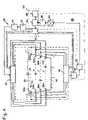
- FIG. 4A preferred embodiment of a device 28 according to the invention is illustrated in FIG. 4 .
- ultrasonic transducers 32 a , 32 b , 34 a , 34 b , 36 a , 36 b , 38 a , 38 bare installed in pairs in the cross section of an open channel 30 to be measured such that paths a, b, c, d in each case span between the members of one of the pairs of transducers 32 a and 32 b , 34 a and 34 b , 36 a and 36 b , 38 a and 38 b that the cross-section of the channel 30 crosses from one side wall to the other at different depths.
- the paths a, b, c, dinclude an angle ⁇ with the direction of flow R of the fluid 20 (see also FIG.
- the ultrasonic transducers 32 a , 32 b , 34 a , 34 b , 36 a , 36 b , 38 a , 38 bare connected over a transmission multiplexer 40 with a signal generator 42 with amplifier 44 and over a reception multiplexer 46 with a signal processing device 48 such that each of the ultrasonic transducers 32 a , 32 b , 34 a , 34 b , 36 a , 36 b , 38 a , 38 b can be switched to a transmitter or receiver.
- the signal processing device 48includes a filter 50 , an amplifier 52 , an analog/digital transducer 54 in which the filtered and amplified signals are digitized from the ultrasonic transducers, and a memory 56 , in which the digitized signals are saved for further analysis.
- a control and analysis device 60contains a fast sequence control system 62 that controls the signal generator 42 , the transmission multiplexer 40 and the reception multiplexer 46 , a calculating device with processor 64 for the analysis of the signals retained in the memory 56 , and an operating- and monitoring device 66 for the operation of the measurement device 28 and for information output.
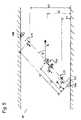
- one ultrasonic transducer of 32 a and 32 b , 34 a and 34 b , 36 a and 36 b , 38 a and 38 bis switched in the known ways to a transmitter, and the other as a receiver respectively.
- only one of the respective ultrasonic transducersis switched to a transmitter at the same time.
- the ultrasonic transducer 32 ais switched to a transmitter, it is stimulated by means of a short electrical signal from the signal generator 42 , such as is illustrated by way of example in FIG.
- the ultrasonic transducer 32 bis switched to a transmitter and an ultrasonic signal 70 is sent in the opposite direction of the path a, which requires a running time t 2 . From the difference of running times t 1 and t 2 , the flow rate can be calculated in known ways.
- the ultrasonic signal 70is also reflected by the particles 73 , 74 , 75 contained in the fluid 20 .
- the reflected ultrasonic signals E 1 , E 2 , E 3are shifted in their frequency (Doppler effect) by means of the proper motion of particles 73 , 74 , 75 .
- the ultrasonic transducers 32 a or 32 b that are switched to a transmitterare switched to a receiver immediately after transmitting the ultrasonic signal 70 . With this it can receive the reflections E 1 , E 2 , E 3 and transmit over the reception multiplexer 46 to the signal processing device 48 for analysis.
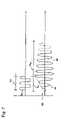
- the natural frequency of the ultrasonic transducermust be quickly absorbed. It is known that ultrasonic transducers possess a time of reverberation t N . In order that it can quickly be received again, a brief time of reverberation t N is desirable. If the ultrasonic transducer is stimulated by means of a simple pulse signal 80 for the length t e as illustrated in FIG. 7 , then the natural frequency of the ultrasonic transducer reacts similarly to the illustrated curve 82 . A reverberation phase 86 with a long time of reverberation t N follows upon a natural frequency phase 84 .
- a long time of reverberation t Ncan be avoided at one of the ultrasonic transducers by means of a constructive configuration.
- the time of reverberation t Ncan also be appreciably shortened, however, by means of a sensible configuration of the transmission signal from the signal generator 42 .
- a transmission signalis illustrated in FIG. 8 , by which a phase shift ⁇ is included after a stimulus part 92 of length t e , after which an absorption part 94 of length t d follows. If the phase shift ⁇ is selected such that the absorption part 94 counteracts the waves 96 of the ultrasonic transducer, then a clearly shortened time of reverberation t N 1 can be achieved. Consequently, the ultrasonic transducer can be used substantially more quickly as a receiver.
- the concentration of particlescan be determined by means of an amplitude analysis.
- the elimination of the reflection waves 73 , 74 , 75 from the transmitter—in FIG. 5 ultrasonic transducer 32 acan be determined.
- the sonic speed v S of the mediummust first be determined. According to FIG. 1 , this results from the path length 1 divided by the average running time 0.5 (t 1 +t 2 ). The elimination 1 (t) of the particles on which the reflection E(t) arose, is thus the result of
- the operatorhas a substantially higher resolution of the measurement cross-section and for this reason a higher accuracy of the measurement results than for the selective measurement of the particle density according to the state of the art.
- the detected reflectionsare filtered in a filter 50 .
- the filter 50is constructed such that only the double-shifted reflections remain unabsorbed.
- the filter parametersare preferably changeable by the sequence control system 62 .
- the range of bandwidth of the filter 50can be matched to the Doppler shift to be expected from the reflections in reliance on the measured flow rate of the fluid 20 .
- Reflections and base signalsin particular can be detected by means of the receivers arranged on the other paths and be pulled up for analysis. In this manner the waves of the reflections and base signals can be resolved locally in great detail and the concentration distribution of the particles accurately determined with it.
- ultrasonic transducers 32 a , 32 b , 34 a , 34 b , 36 a , 36 b , 38 a , 38 bdesigned for the measurement of the amount of ultrasonic running time
- additional, separate ultrasonic transducers 32 ccan be designed for the detection of the reflections E 1 , E 2 , E 3 . Either of the reflections E 1 , E 2 , E 3 can then be detected with these separate ultrasonic transducers 32 c such that a higher local resolution of the concentration of particles is possible.
- a spatial resolution of the concentration of particlesis also possible.
- the separate ultrasonic transducersare used for the detection of the reflections. This offers the opportunity to use specially-designed transducers that are particularly matched to their function, the reception.
- the ultrasonic transducers 32 a , 32 b , 34 a , 34 b , 36 a , 36 b , 38 a , 38 bthat should function as transmitters for the measurement of the amount of running time, as a rule posses a minor radiation angle at which the vectored signal is given off, and also for this reason a mostly small reception angle.
- it is advantageous for the detection of the radiated signalif the receiver possesses a large reception angle.
Landscapes
- Physics & Mathematics (AREA)
- General Physics & Mathematics (AREA)
- Biochemistry (AREA)
- Health & Medical Sciences (AREA)
- Life Sciences & Earth Sciences (AREA)
- Chemical & Material Sciences (AREA)
- Analytical Chemistry (AREA)
- Fluid Mechanics (AREA)
- General Health & Medical Sciences (AREA)
- Immunology (AREA)
- Pathology (AREA)
- Acoustics & Sound (AREA)
- Electromagnetism (AREA)
- Investigating Or Analyzing Materials By The Use Of Ultrasonic Waves (AREA)
Abstract
Description
Claims (8)
Applications Claiming Priority (3)
| Application Number | Priority Date | Filing Date | Title |
|---|---|---|---|
| DE10224294.1 | 2002-05-31 | ||
| DE10224294ADE10224294A1 (en) | 2002-05-31 | 2002-05-31 | Method for ultrasonic transit time quantity measurement |
| PCT/DE2003/001783WO2003102512A1 (en) | 2002-05-31 | 2003-05-31 | Ultrasonic measurement of the running time and quantity for detecting the concentration of particles in a flowing fluid |
Publications (2)
| Publication Number | Publication Date |
|---|---|
| US20060005611A1 US20060005611A1 (en) | 2006-01-12 |
| US7270001B2true US7270001B2 (en) | 2007-09-18 |
Family
ID=29594208
Family Applications (1)
| Application Number | Title | Priority Date | Filing Date |
|---|---|---|---|
| US10/516,030Expired - Fee RelatedUS7270001B2 (en) | 2002-05-31 | 2003-05-31 | Ultrasonic measurement of the running time and quantity for detecting the concentration of particles in a flowing fluid |
Country Status (5)
| Country | Link |
|---|---|
| US (1) | US7270001B2 (en) |
| EP (1) | EP1554548B1 (en) |
| AU (1) | AU2003250741A1 (en) |
| DE (2) | DE10224294A1 (en) |
| WO (1) | WO2003102512A1 (en) |
Cited By (4)
| Publication number | Priority date | Publication date | Assignee | Title |
|---|---|---|---|---|
| US20070084286A1 (en)* | 2003-05-14 | 2007-04-19 | Kemal Ajay | Sensing apparatus and method |
| US20070101809A1 (en)* | 2005-11-07 | 2007-05-10 | Roesner Bruce B | Fluid level detection using RF |
| US20070119239A1 (en)* | 2005-11-30 | 2007-05-31 | Aba Priev | Method and apparatus for determination of the concentration of particles in multi-component fluid systems |
| US20160207153A1 (en)* | 2013-05-15 | 2016-07-21 | Air Products And Chemicals, Inc. | Ultrasonic liquid level sensing systems |
Families Citing this family (14)
| Publication number | Priority date | Publication date | Assignee | Title |
|---|---|---|---|---|
| DE102006033611B4 (en)* | 2006-07-18 | 2010-04-08 | Hydrometer Gmbh | Gas phase correction for ultrasonic flowmeter |
| DE102007008505A1 (en)* | 2007-02-21 | 2008-08-28 | Siemens Ag | Method of operating a piezoelectric transducer and transducer device |
| DE102009019497B4 (en) | 2009-05-04 | 2014-07-17 | Wittenstein Ag | Method for the examination of a medium |
| DE102009046159A1 (en) | 2009-10-29 | 2011-05-05 | Endress + Hauser Flowtec Ag | Ultrasonic flow and particle measuring system |
| DE102010031128A1 (en) | 2010-07-08 | 2012-01-12 | Endress + Hauser Flowtec Ag | Ultrasonic particle measuring system |
| DE102010031129A1 (en) | 2010-07-08 | 2012-01-12 | Endress + Hauser Flowtec Ag | Ultrasonic particle measuring system |
| KR101810723B1 (en)* | 2010-09-03 | 2017-12-19 | 로스 알라모스 내셔널 씨큐어리티 엘엘씨 | Apparatus and method for noninvasive particle detection using doppler spectroscopy |
| DE102011012992A1 (en)* | 2011-03-03 | 2012-09-06 | Continental Automotive Gmbh | Arrangement and method for determining a concentration of a component of a fluid mixture |
| JP5867708B2 (en)* | 2012-01-10 | 2016-02-24 | 横河電機株式会社 | Ultrasonic flow meter |
| DE102013102810A1 (en) | 2012-04-12 | 2013-10-17 | Endress + Hauser Conducta Gesellschaft für Mess- und Regeltechnik mbH + Co. KG | Method for detecting and / or monitoring the solids content of raw water production from wells |
| IN2015DN03971A (en)* | 2012-10-11 | 2015-10-02 | Rubicon Res Pty Ltd | |
| JP6468790B2 (en)* | 2014-10-21 | 2019-02-13 | 日立Geニュークリア・エナジー株式会社 | Ultrasonic leak detection device and leak detection method using the same |
| DE102015106695A1 (en) | 2015-04-29 | 2016-11-03 | Manuel Haide | Method and device for flow measurement |
| GB201713895D0 (en) | 2017-08-30 | 2017-10-11 | Sentec Ltd | Transducer drive and damping technique |
Citations (10)
| Publication number | Priority date | Publication date | Assignee | Title |
|---|---|---|---|---|
| US3575050A (en) | 1968-12-04 | 1971-04-13 | Panametrics | Fluid flowmeter |
| US3731532A (en) | 1972-01-14 | 1973-05-08 | Thomson Csf | Ultrasonic flowmeter and method of metering |
| US3779070A (en)* | 1971-11-23 | 1973-12-18 | Autometrics Co | Particle size and percent solids monitor |
| GB2156075A (en) | 1984-03-15 | 1985-10-02 | Micro Pure Systems Inc | Ultrasonic flow discontinuity identification |
| JPS61288185A (en) | 1985-06-14 | 1986-12-18 | Omron Tateisi Electronics Co | Ultrasonic sensor |
| US4718269A (en) | 1985-04-17 | 1988-01-12 | Sticting "Stichting Waterbouwkundig Laboratorium" | System for measuring particle transport in a fluid |
| US5125514A (en) | 1988-10-11 | 1992-06-30 | Maschinenfabrik Rieter Ag | Recognizing unwanted material in textile fibers |
| US5533408A (en) | 1993-12-23 | 1996-07-09 | Endress + Hauser Flowtec Ag | Clamp-on ultrasonic volumetric flowmeter |
| JP2000321104A (en) | 1999-05-11 | 2000-11-24 | Matsushita Electric Ind Co Ltd | Ultrasonic flow meter |
| US6481268B1 (en)* | 1999-10-12 | 2002-11-19 | Baker Hughes, Inc. | Particle measurement by acoustic speckle |
Family Cites Families (8)
| Publication number | Priority date | Publication date | Assignee | Title |
|---|---|---|---|---|
| JPS54125061A (en)* | 1978-03-23 | 1979-09-28 | Toshiba Corp | Ultrasonic type instrument |
| DE3409595A1 (en)* | 1984-03-15 | 1985-09-19 | Micro Pure Systems, Inc., Smithfield, R.I. | Method and device for identifying discontinuities in a flow |
| DE4027030A1 (en)* | 1990-08-27 | 1992-03-05 | Honeywell Regelsysteme Gmbh | Measuring speed of flow by ultrasonic echo signals - using defined time window in reflex method for base and surface echoes for correlative evaluation |
| DE4232526C2 (en)* | 1992-09-29 | 1996-06-20 | Georg F Wagner | Device for measuring small liquid flows with high-frequency ultrasound and their use |
| DE19653001C2 (en)* | 1996-12-19 | 2002-06-20 | Schubert & Salzer Control Syst | Device for determining the flow rate and the reflector concentration of a liquid |
| DE19740549C2 (en)* | 1997-09-15 | 2002-09-26 | Frank Obergrieser | Method for measuring flow characteristics and other process parameters |
| DE19808701C2 (en)* | 1998-03-02 | 2000-01-20 | Georg F Wagner | Flow measuring device |
| US6550345B1 (en)* | 2000-09-11 | 2003-04-22 | Daniel Industries, Inc. | Technique for measurement of gas and liquid flow velocities, and liquid holdup in a pipe with stratified flow |
- 2002
- 2002-05-31DEDE10224294Apatent/DE10224294A1/ennot_activeWithdrawn
- 2003
- 2003-05-31EPEP03755916.8Apatent/EP1554548B1/ennot_activeExpired - Lifetime
- 2003-05-31AUAU2003250741Apatent/AU2003250741A1/ennot_activeAbandoned
- 2003-05-31DEDE10393301Tpatent/DE10393301D2/ennot_activeWithdrawn - After Issue
- 2003-05-31USUS10/516,030patent/US7270001B2/ennot_activeExpired - Fee Related
- 2003-05-31WOPCT/DE2003/001783patent/WO2003102512A1/ennot_activeApplication Discontinuation
Patent Citations (14)
| Publication number | Priority date | Publication date | Assignee | Title |
|---|---|---|---|---|
| US3575050A (en) | 1968-12-04 | 1971-04-13 | Panametrics | Fluid flowmeter |
| US3779070A (en)* | 1971-11-23 | 1973-12-18 | Autometrics Co | Particle size and percent solids monitor |
| US3731532A (en) | 1972-01-14 | 1973-05-08 | Thomson Csf | Ultrasonic flowmeter and method of metering |
| GB2156075A (en) | 1984-03-15 | 1985-10-02 | Micro Pure Systems Inc | Ultrasonic flow discontinuity identification |
| US4718269A (en) | 1985-04-17 | 1988-01-12 | Sticting "Stichting Waterbouwkundig Laboratorium" | System for measuring particle transport in a fluid |
| JPS61288185A (en) | 1985-06-14 | 1986-12-18 | Omron Tateisi Electronics Co | Ultrasonic sensor |
| US5125514A (en) | 1988-10-11 | 1992-06-30 | Maschinenfabrik Rieter Ag | Recognizing unwanted material in textile fibers |
| US5533408A (en) | 1993-12-23 | 1996-07-09 | Endress + Hauser Flowtec Ag | Clamp-on ultrasonic volumetric flowmeter |
| JP2000321104A (en) | 1999-05-11 | 2000-11-24 | Matsushita Electric Ind Co Ltd | Ultrasonic flow meter |
| US6481268B1 (en)* | 1999-10-12 | 2002-11-19 | Baker Hughes, Inc. | Particle measurement by acoustic speckle |
| US6698276B2 (en)* | 1999-10-12 | 2004-03-02 | Baker Hughes, Inc. | Method and apparatus for determining particle size distribution by acoustic speckle |
| US6698277B2 (en)* | 1999-10-12 | 2004-03-02 | Baker Hughes, Inc. | Method and apparatus for measuring concentration using acoustic speckle |
| US6748815B2 (en)* | 1999-10-12 | 2004-06-15 | Baker Hughes, Inc | Method for determining particle size |
| US6796195B2 (en)* | 1999-10-12 | 2004-09-28 | Baker Hughes, Inc. | Apparatus for determining particle size |
Cited By (10)
| Publication number | Priority date | Publication date | Assignee | Title |
|---|---|---|---|---|
| US20070084286A1 (en)* | 2003-05-14 | 2007-04-19 | Kemal Ajay | Sensing apparatus and method |
| US8224621B2 (en) | 2003-05-14 | 2012-07-17 | Vision Fire & Security Pty Ltd | Sensing apparatus and method |
| US8892399B2 (en) | 2003-05-14 | 2014-11-18 | Xtralis Technologies Ltd | Sensing apparatus and method |
| US9746363B2 (en) | 2003-05-14 | 2017-08-29 | Garrett Thermal Systems Limited | Sensing apparatus and method |
| US20070101809A1 (en)* | 2005-11-07 | 2007-05-10 | Roesner Bruce B | Fluid level detection using RF |
| US7458260B2 (en)* | 2005-11-07 | 2008-12-02 | Claridy Solutions, Inc. | Fluid level detection using RF |
| US20070119239A1 (en)* | 2005-11-30 | 2007-05-31 | Aba Priev | Method and apparatus for determination of the concentration of particles in multi-component fluid systems |
| US7484414B2 (en)* | 2005-11-30 | 2009-02-03 | Nanoalert Ltd. | Method and apparatus for determination of the concentration of particles in multi-component fluid systems |
| US20160207153A1 (en)* | 2013-05-15 | 2016-07-21 | Air Products And Chemicals, Inc. | Ultrasonic liquid level sensing systems |
| US9550260B2 (en)* | 2013-05-15 | 2017-01-24 | Air Products And Chemicals, Inc. | Ultrasonic liquid level sensing systems |
Also Published As
| Publication number | Publication date |
|---|---|
| US20060005611A1 (en) | 2006-01-12 |
| EP1554548A1 (en) | 2005-07-20 |
| AU2003250741A1 (en) | 2003-12-19 |
| DE10393301D2 (en) | 2005-05-25 |
| DE10224294A1 (en) | 2004-01-15 |
| EP1554548B1 (en) | 2019-05-22 |
| WO2003102512A1 (en) | 2003-12-11 |
Similar Documents
| Publication | Publication Date | Title |
|---|---|---|
| US7270001B2 (en) | Ultrasonic measurement of the running time and quantity for detecting the concentration of particles in a flowing fluid | |
| US11391699B2 (en) | Turbidity sensor based on ultrasound measurements | |
| KR100808729B1 (en) | Simultaneous determination of flow rate and concentration in multiphase flow | |
| US6983208B2 (en) | Method and apparatus for combined measurements of concentration, distribution and flow velocity of suspended solids | |
| US6487916B1 (en) | Ultrasonic flow metering system | |
| US9031797B2 (en) | Multiphase flow measurement | |
| CN102288235B (en) | Double-track mixed type ultrasonic flowmeter and measuring method | |
| WO2004063675A3 (en) | Apparatus and method using an array of ultrasonic sensors for determining the velocity of a fluid within a pipe | |
| JP5960721B2 (en) | Apparatus and method for measuring the flow rate of a fluid or fluid component in a pipeline | |
| NO333312B1 (en) | Apparatus and method for milling flow rates in a metal stirrer | |
| US4397191A (en) | Liquid velocity measurement system | |
| JP2002340644A (en) | Ultrasonic flow and flow velocity-measuring instrument and ultrasonic flow and flow velocity-measuring method | |
| US12270692B2 (en) | Optical fluid flow velocity measurement | |
| CN219178622U (en) | Water flow monitoring device and system | |
| RU2169350C2 (en) | Process measuring and controlling parameters of flow of liquid or gas in vessel with elastic walls | |
| RU2210764C1 (en) | Procedure determining density of liquids and device for its implementation | |
| JPH0735589A (en) | Flow rate concentration measuring device | |
| Dwinovantyo et al. | Estimation of Suspended Sediment Concentration by Using Mobile ADCP Instrument | |
| JP3021671B2 (en) | Vortex flow meter | |
| Carlson | Ultrasound measurements in moving multi-phase suspensions | |
| MXPA98008800A (en) | Device for detecting the concrete speed profile that flows in a tube | |
| HK1052549B (en) | Simultaneous determination of multiphase flowrates and concentrations |
Legal Events
| Date | Code | Title | Description |
|---|---|---|---|
| AS | Assignment | Owner name:SYSTEC CONROLS MESS UND REGELTECHNIK GMBH, GERMANY Free format text:ASSIGNMENT OF ASSIGNORS INTEREST;ASSIGNOR:BETZ, OLIVER;REEL/FRAME:016529/0439 Effective date:20041125 | |
| AS | Assignment | Owner name:SYSTEC CONTROLS MESS UND REGELTECHNIK GMBH, GERMAN Free format text:CORRECTIVE TO CORRECT REEL 016529, FRAME 0439 RE-RECORD TO CORRECT ASSIGNEE'S NAME AND ASSIGNEE'S ADDRESS;ASSIGNOR:BETZ, OLIVER;REEL/FRAME:016854/0838 Effective date:20041125 | |
| AS | Assignment | Owner name:SYSTEC CONTROLS MESS UND REGELTECHNIK GMBH, GERMAN Free format text:ASSIGNMENT OF ASSIGNORS INTEREST;ASSIGNOR:BETZ, OLIVER;REEL/FRAME:017109/0287 Effective date:20041125 | |
| STCF | Information on status: patent grant | Free format text:PATENTED CASE | |
| FPAY | Fee payment | Year of fee payment:4 | |
| FPAY | Fee payment | Year of fee payment:8 | |
| FEPP | Fee payment procedure | Free format text:MAINTENANCE FEE REMINDER MAILED (ORIGINAL EVENT CODE: REM.); ENTITY STATUS OF PATENT OWNER: LARGE ENTITY | |
| LAPS | Lapse for failure to pay maintenance fees | Free format text:PATENT EXPIRED FOR FAILURE TO PAY MAINTENANCE FEES (ORIGINAL EVENT CODE: EXP.); ENTITY STATUS OF PATENT OWNER: LARGE ENTITY | |
| STCH | Information on status: patent discontinuation | Free format text:PATENT EXPIRED DUE TO NONPAYMENT OF MAINTENANCE FEES UNDER 37 CFR 1.362 | |
| FP | Lapsed due to failure to pay maintenance fee | Effective date:20190918 |