US7269430B2 - Frame format for high data throughput wireless local area network transmissions - Google Patents
Frame format for high data throughput wireless local area network transmissionsDownload PDFInfo
- Publication number
- US7269430B2 US7269430B2US10/778,751US77875104AUS7269430B2US 7269430 B2US7269430 B2US 7269430B2US 77875104 AUS77875104 AUS 77875104AUS 7269430 B2US7269430 B2US 7269430B2
- Authority
- US
- United States
- Prior art keywords
- channel
- subcarriers
- training sequence
- transmitted via
- mhz
- Prior art date
- Legal status (The legal status is an assumption and is not a legal conclusion. Google has not performed a legal analysis and makes no representation as to the accuracy of the status listed.)
- Active, expires
Links
- 230000005540biological transmissionEffects0.000titleclaimsabstractdescription20
- 238000012549trainingMethods0.000claimsabstractdescription92
- 238000012545processingMethods0.000claimsdescription39
- 238000004891communicationMethods0.000description65
- 239000000969carrierSubstances0.000description24
- 238000010586diagramMethods0.000description22
- 230000001413cellular effectEffects0.000description8
- 230000003595spectral effectEffects0.000description8
- 238000006243chemical reactionMethods0.000description7
- 238000001914filtrationMethods0.000description7
- 230000006870functionEffects0.000description7
- 230000010355oscillationEffects0.000description7
- 230000008878couplingEffects0.000description5
- 238000010168coupling processMethods0.000description5
- 238000005859coupling reactionMethods0.000description5
- 230000001419dependent effectEffects0.000description2
- 230000009977dual effectEffects0.000description2
- 239000011159matrix materialSubstances0.000description2
- 238000000034methodMethods0.000description2
- 238000011084recoveryMethods0.000description2
- 238000000638solvent extractionMethods0.000description2
- 238000001514detection methodMethods0.000description1
- 230000002349favourable effectEffects0.000description1
- 238000013507mappingMethods0.000description1
- 238000010295mobile communicationMethods0.000description1
- 230000001105regulatory effectEffects0.000description1
- 238000001228spectrumMethods0.000description1
- 230000003068static effectEffects0.000description1
Images


Classifications
- H—ELECTRICITY
- H04—ELECTRIC COMMUNICATION TECHNIQUE
- H04W—WIRELESS COMMUNICATION NETWORKS
- H04W99/00—Subject matter not provided for in other groups of this subclass
- H—ELECTRICITY
- H04—ELECTRIC COMMUNICATION TECHNIQUE
- H04L—TRANSMISSION OF DIGITAL INFORMATION, e.g. TELEGRAPHIC COMMUNICATION
- H04L25/00—Baseband systems
- H04L25/02—Details ; arrangements for supplying electrical power along data transmission lines
- H04L25/0202—Channel estimation
- H04L25/0204—Channel estimation of multiple channels
- H—ELECTRICITY
- H04—ELECTRIC COMMUNICATION TECHNIQUE
- H04L—TRANSMISSION OF DIGITAL INFORMATION, e.g. TELEGRAPHIC COMMUNICATION
- H04L25/00—Baseband systems
- H04L25/02—Details ; arrangements for supplying electrical power along data transmission lines
- H04L25/0202—Channel estimation
- H04L25/0224—Channel estimation using sounding signals
- H04L25/0226—Channel estimation using sounding signals sounding signals per se
- H—ELECTRICITY
- H04—ELECTRIC COMMUNICATION TECHNIQUE
- H04L—TRANSMISSION OF DIGITAL INFORMATION, e.g. TELEGRAPHIC COMMUNICATION
- H04L27/00—Modulated-carrier systems
- H04L27/26—Systems using multi-frequency codes
- H04L27/2601—Multicarrier modulation systems
- H04L27/2602—Signal structure
- H—ELECTRICITY
- H04—ELECTRIC COMMUNICATION TECHNIQUE
- H04L—TRANSMISSION OF DIGITAL INFORMATION, e.g. TELEGRAPHIC COMMUNICATION
- H04L5/00—Arrangements affording multiple use of the transmission path
- H04L5/0001—Arrangements for dividing the transmission path
- H04L5/0014—Three-dimensional division
- H04L5/0023—Time-frequency-space
- H—ELECTRICITY
- H04—ELECTRIC COMMUNICATION TECHNIQUE
- H04L—TRANSMISSION OF DIGITAL INFORMATION, e.g. TELEGRAPHIC COMMUNICATION
- H04L5/00—Arrangements affording multiple use of the transmission path
- H04L5/003—Arrangements for allocating sub-channels of the transmission path
- H04L5/0048—Allocation of pilot signals, i.e. of signals known to the receiver
- H—ELECTRICITY
- H04—ELECTRIC COMMUNICATION TECHNIQUE
- H04L—TRANSMISSION OF DIGITAL INFORMATION, e.g. TELEGRAPHIC COMMUNICATION
- H04L5/00—Arrangements affording multiple use of the transmission path
- H04L5/0091—Signalling for the administration of the divided path, e.g. signalling of configuration information
- H—ELECTRICITY
- H04—ELECTRIC COMMUNICATION TECHNIQUE
- H04L—TRANSMISSION OF DIGITAL INFORMATION, e.g. TELEGRAPHIC COMMUNICATION
- H04L27/00—Modulated-carrier systems
- H04L27/26—Systems using multi-frequency codes
- H04L27/2601—Multicarrier modulation systems
- H04L27/2602—Signal structure
- H04L27/2603—Signal structure ensuring backward compatibility with legacy system
- H—ELECTRICITY
- H04—ELECTRIC COMMUNICATION TECHNIQUE
- H04W—WIRELESS COMMUNICATION NETWORKS
- H04W84/00—Network topologies
- H04W84/02—Hierarchically pre-organised networks, e.g. paging networks, cellular networks, WLAN [Wireless Local Area Network] or WLL [Wireless Local Loop]
- H04W84/10—Small scale networks; Flat hierarchical networks
- H04W84/12—WLAN [Wireless Local Area Networks]
- Y—GENERAL TAGGING OF NEW TECHNOLOGICAL DEVELOPMENTS; GENERAL TAGGING OF CROSS-SECTIONAL TECHNOLOGIES SPANNING OVER SEVERAL SECTIONS OF THE IPC; TECHNICAL SUBJECTS COVERED BY FORMER USPC CROSS-REFERENCE ART COLLECTIONS [XRACs] AND DIGESTS
- Y10—TECHNICAL SUBJECTS COVERED BY FORMER USPC
- Y10S—TECHNICAL SUBJECTS COVERED BY FORMER USPC CROSS-REFERENCE ART COLLECTIONS [XRACs] AND DIGESTS
- Y10S370/00—Multiplex communications
- Y10S370/901—Wide area network
- Y—GENERAL TAGGING OF NEW TECHNOLOGICAL DEVELOPMENTS; GENERAL TAGGING OF CROSS-SECTIONAL TECHNOLOGIES SPANNING OVER SEVERAL SECTIONS OF THE IPC; TECHNICAL SUBJECTS COVERED BY FORMER USPC CROSS-REFERENCE ART COLLECTIONS [XRACs] AND DIGESTS
- Y10—TECHNICAL SUBJECTS COVERED BY FORMER USPC
- Y10S—TECHNICAL SUBJECTS COVERED BY FORMER USPC CROSS-REFERENCE ART COLLECTIONS [XRACs] AND DIGESTS
- Y10S370/00—Multiplex communications
- Y10S370/908—Local area network
Definitions
- This inventionrelates generally to wireless communication systems and more particularly to high data throughput communications in such systems.
- Communication systemsare known to support wireless and wire lined communications between wireless and/or wire lined communication devices. Such communication systems range from national and/or international cellular telephone systems to the Internet to point-to-point in-home wireless networks. Each type of communication system is constructed, and hence operates, in accordance with one or more communication standards. For instance, wireless communication systems may operate in accordance with one or more standards including, but not limited to, IEEE 802.11, Bluetooth, advanced mobile phone services (AMPS), digital AMPS, global system for mobile communications (GSM), code division multiple access (CDMA), local multi-point distribution systems (LMDS), multi-channel-multi-point distribution systems (MMDS), and/or variations thereof.
- GSMglobal system for mobile communications
- CDMAcode division multiple access
- LMDSlocal multi-point distribution systems
- MMDSmulti-channel-multi-point distribution systems
- a wireless communication devicesuch as a cellular telephone, two-way radio, personal digital assistant (PDA), personal computer (PC), laptop computer, home entertainment equipment, et cetera communicates directly or indirectly with other wireless communication devices.
- the participating wireless communication devicestune their receivers and transmitters to the same channel or channels (e.g., one of the plurality of radio frequency (RF) carriers of the wireless communication system) and communicate over that channel(s).
- RFradio frequency
- each wireless communication devicecommunicates directly with an associated base station (e.g., for cellular services) and/or an associated access point (e.g., for an in-home or in-building wireless network) via an assigned channel.
- the associated base stations and/or associated access pointscommunicate with each other directly, via a system controller, via the public switch telephone network, via the Internet, and/or via some other wide area network.
- each wireless communication deviceFor each wireless communication device to participate in wireless communications, it includes a built-in radio transceiver (i.e., receiver and transmitter) or is coupled to an associated radio transceiver (e.g., a station for in-home and/or in-building wireless communication networks, RF modem, etc.).
- the transmitterincludes a data modulation stage, one or more intermediate frequency stages, and a power amplifier.
- the data modulation stageconverts raw data into baseband signals in accordance with a particular wireless communication standard.
- the one or more intermediate frequency stagesmix the baseband signals with one or more local oscillations to produce RF signals.
- the power amplifieramplifies the RF signals prior to transmission via an antenna.
- the receiveris coupled to the antenna and includes a low noise amplifier, one or more intermediate frequency stages, a filtering stage, and a data recovery stage.
- the low noise amplifierreceives inbound RF signals via the antenna and amplifies them.
- the one or more intermediate frequency stagesmix the amplified RF signals with one or more local oscillations to convert the amplified RF signal into baseband signals or intermediate frequency (IF) signals.
- the filtering stagefilters the baseband signals or the IF signals to attenuate unwanted out of band signals to produce filtered signals.
- the data recovery stagerecovers raw data from the filtered signals in accordance with the particular wireless communication standard.
- the assigned channel, or channels, over which the direct or indirect communication occursis defined by the standard, or standards, supported by the wireless communication devices.
- IEEE 802.11 (a) and (g)provide a channel spectral mask for 20 MHz orthogonal frequency division multiplexing (OFDM) channels.
- the standardsalso define the manner in which devices communicate over the channel.
- the IEEE 802.11 (a) and (g) standardsdefine a frame structure for communicating via a channel in a WLAN.
- the frameincludes a preamble and a variable length data segment.
- the preambleincludes a short training sequence, a long training sequence, and a signal field, which provides rate information of the data and length of the data segment.
- Each receiving wireless communication deviceuses the frame preamble for signal detection, automatic gain control adjustments, diversity determinations, frequency adjustments, timing synchronization, and channel and fine frequency offset estimation.
- Such a frame formatallows the wireless communication devices of a WLAN to communicate in a very specific manner. This frame format, however, does not accommodate higher data throughput rates, with backward compatibility to existing WLAN equipment, and various wireless channel configurations.
- a frame format for high data throughput wireless local area network transmissionsincludes a first preamble segment, a second preamble segment, and a variable length data segment.
- the first preamble segmentincludes a first training sequence, a second training sequence, and a high throughput channel indication, wherein the first training sequence is within a first set of subcarriers of a channel and the second training sequence is within a second set of subcarriers of the channel, wherein the first set of subcarriers is a subset of the second set of subcarriers.
- the second preamble segmentincludes a third training sequence within a third set of subcarriers of the channel, wherein the second set of subcarriers is a subset of the third set of subcarriers.
- the variable length data segmentutilizes the third set of subcarriers to convey data.
- an apparatus for transmitting a frame within a high throughput wireless local area networkincludes a processing module, memory, and a radio frequency transmission circuit.
- the memoryis operably coupled to the processing module, wherein the memory stores operational instructions that cause the processing module to prepare the frame by: generating a first preamble segment including a first training sequence, a second training sequence, and a high throughput channel indication, wherein the first training sequence is within a first set of subcarriers of a channel and the second training sequence is within a second set of subcarriers of the channel, wherein the first set of subcarriers is a subset of the second set of subcarriers; generating a second preamble segment including a third training sequence within a third set of subcarriers of the channel, wherein the second set of subcarriers is a subset of the third set of subcarriers; generating a variable length data segment utilizing the third set of subcarriers to convey data.
- the radio frequency transmission circuitis operably coupled to transmit the first pre
- FIG. 1is a schematic block diagram of a wireless communication system in accordance with the present invention
- FIG. 2is a schematic block diagram of a wireless communication device in accordance with the present invention.
- FIG. 3is a diagram depicting frequency bands that may be used in accordance with the present invention.
- FIG. 4is a diagram depicting channel partitioning of a frequency band in accordance with the present invention.
- FIG. 5is a diagram of transmitting frames via an RF channel in accordance with an embodiment of the present invention.
- FIG. 6is a diagram of a frame format in accordance with an embodiment of the present invention.
- FIG. 7is a diagram of channel configurations in accordance with an embodiment of the present invention.
- FIG. 8is a diagram of a first training sequence in accordance with the present invention.
- FIG. 9is a diagram of a second training sequence in accordance with the present invention.
- FIG. 10is a diagram of a third training sequence in accordance with the present invention.
- FIG. 11is a diagram of an alternative third training sequence in accordance with the present invention.
- FIG. 12is a diagram of another third training sequence in accordance with the present invention.
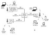
- FIG. 1is a schematic block diagram illustrating a communication system 10 that includes a plurality of base stations and/or access points 12 - 16 , a plurality of wireless communication devices 18 - 32 and a network hardware component 34 .
- the wireless communication devices 18 - 32may be laptop host computers 18 and 26 , personal digital assistant hosts 20 and 30 , personal computer hosts 24 and 32 and/or cellular telephone hosts 22 and 28 .
- the details of the wireless communication deviceswill be described in greater detail with reference to FIG. 2 .
- the base stations or access points 12 - 16are operably coupled to the network hardware 34 via local area network connections 36 , 38 and 40 .
- the network hardware 34which may be a router, switch, bridge, modem, system controller, et cetera provides a wide area network connection 42 for the communication system 10 .
- Each of the base stations or access points 12 - 16has an associated antenna or antenna array to communicate with the wireless communication devices in its area via one or more configurable channels within one or more frequency bands.
- the wireless communication devicesregister with a particular base station or access point 12 - 14 to receive services from the communication system 10 .
- For direct connectionsi.e., point-to-point communications
- wireless communication devicescommunicate directly via an allocated channel of the configurable channels.
- each wireless communication deviceincludes a built-in radio and/or is coupled to a radio.
- the radioincludes a highly linear amplifier and/or programmable multi-stage amplifier as disclosed herein to enhance performance, reduce costs, reduce size, and/or enhance broadband applications.
- FIG. 2is a schematic block diagram illustrating a wireless communication device that includes the host device 18 - 32 and an associated radio 60 .
- the radio 60is a built-in component.
- the radio 60may be built-in or an externally coupled component.
- the host device 18 - 32includes a processing module 50 , memory 52 , radio interface 54 , input interface 58 and output interface 56 .
- the processing module 50 and memory 52execute the corresponding instructions that are typically done by the host device. For example, for a cellular telephone host device, the processing module 50 performs the corresponding communication functions in accordance with a particular cellular telephone standard.
- the radio interface 54allows data to be received from and sent to the radio 60 .
- the radio interface 54For data received from the radio 60 (e.g., inbound data), the radio interface 54 provides the data to the processing module 50 for further processing and/or routing to the output interface 56 .
- the output interface 56provides connectivity to an output display device such as a display, monitor, speakers, et cetera such that the received data may be displayed.
- the radio interface 54also provides data from the processing module 50 to the radio 60 .
- the processing module 50may receive the outbound data from an input device such as a keyboard, keypad, microphone, et cetera via the input interface 58 or generate the data itself.
- the processing module 50may perform a corresponding host function on the data and/or route it to the radio 60 via the radio interface 54 .
- Radio 60includes a host interface 62 , digital receiver processing module 64 , an analog-to-digital converter 66 , a filtering/gain module 68 , an IF mixing down conversion stage 70 , a receiver filter 71 , a low noise amplifier 72 , a transmitter/receiver switch 73 , a local oscillation module 74 , memory 75 , a digital transmitter processing module 76 , a digital-to-analog converter 78 , a filtering/gain module 80 , an IF mixing up conversion stage 82 , a power amplifier 84 , a transmitter filter module 85 , and an antenna 86 .
- the antenna 86may be a single antenna that is shared by the transmit and receive paths as regulated by the Tx/Rx switch 73 , or may include separate antennas for the transmit path and receive path.
- the antenna implementationwill depend on the particular standard to which the wireless communication device is compliant.
- the digital receiver processing module 64 and the digital transmitter processing module 76in combination with operational instructions stored in memory 75 , execute digital receiver baseband functions and digital transmitter baseband functions, respectively.
- the digital receiver functionsinclude, but are not limited to, digital intermediate frequency to baseband conversion, demodulation, constellation demapping, decoding, and/or descrambling.
- the digital transmitter functionsinclude, but are not limited to, scrambling, encoding, constellation mapping, modulation, and/or digital baseband to IF conversion.
- the digital receiver and transmitter processing modules 64 and 76may be implemented using a shared processing device, individual processing devices, or a plurality of processing devices.
- Such a processing devicemay be a microprocessor, micro-controller, digital signal processor, microcomputer, central processing unit, field programmable gate array, programmable logic device, state machine, logic circuitry, analog circuitry, digital circuitry, and/or any device that manipulates signals (analog and/or digital) based on operational instructions.
- the memory 75may be a single memory device or a plurality of memory devices.
- Such a memory devicemay be a read-only memory, random access memory, volatile memory, non-volatile memory, static memory, dynamic memory, flash memory, and/or any device that stores digital information.
- the processing module 64 and/or 76implements one or more of its functions via a state machine, analog circuitry, digital circuitry, and/or logic circuitry
- the memory storing the corresponding operational instructionsis embedded with the circuitry comprising the state machine, analog circuitry, digital circuitry, and/or logic circuitry.
- the radio 60receives outbound data 94 from the host device via the host interface 62 .
- the host interface 62routes the outbound data 94 to the digital transmitter processing module 76 , which processes the outbound data 94 in accordance with a particular wireless communication standard (e.g., IEEE 802.11 Bluetooth, et cetera) to produce digital transmission formatted data 96 .
- the digital transmission formatted data 96will be a digital base-band signal or a digital low IF signal, where the low IF typically will be in the frequency range of one hundred kilohertz to a few megahertz. Further, the digital transmission formatted data 96 will be based on the channel width of the RF channel on which the data 96 will ultimately be transmitted.
- the channel widthmay be 10 MHz, 20 MHz, or 40 MHz.
- a 10 MHz wide channelmay include 32 subcarrier frequencies
- a 20 MHz wide channelmay include 64 subcarrier frequencies
- a 40 MHz wide channelmay include 128 subcarrier frequencies, where the number of subcarriers used per channel is at least partially based on the spectral masked configured for the channel. Configuring the spectral mask will be described in greater detail with reference to FIGS. 3-6 .
- the digital-to-analog converter 78converts the digital transmission formatted data 96 from the digital domain to the analog domain.
- the filtering/gain module 80filters and/or adjusts the gain of the analog signal prior to providing it to the IF mixing stage 82 .
- the IF mixing stage 82converts the analog baseband or low IF signal into an RF signal based on a transmitter local oscillation 83 provided by local oscillation module 74 .
- the power amplifier 84amplifies the RF signal to produce outbound RF signal 98 , which is filtered by the transmitter filter module 85 .
- the antenna 86transmits the outbound RF signal 98 to a targeted device such as a base station, an access point and/or another wireless communication device. Note that the bandpass regions of the filters 80 and 85 are dependent upon the configured spectral mask for the RF transmission, which may be determined by the digital transmitter processing module 76 .
- the radio 60also receives an inbound RF signal 88 via the antenna 86 , which was transmitted by a base station, an access point, or another wireless communication device.
- the antenna 86provides the inbound RF signal 88 to the receiver filter module 71 via the Tx/Rx switch 73 , where the Rx filter 71 bandpass filters the inbound RF signal 88 .
- the Rx filter 71provides the filtered RF signal to low noise amplifier 72 , which amplifies the signal 88 to produce an amplified inbound RF signal.
- the low noise amplifier 72provides the amplified inbound RF signal to the IF mixing module 70 , which directly converts the amplified inbound RF signal into an inbound low IF signal or baseband signal based on a receiver local oscillation 81 provided by local oscillation module 74 .
- the down conversion module 70provides the inbound low IF signal or baseband signal to the filtering/gain module 68 .
- the filtering/gain module 68filters and/or gains the inbound low IF signal or the inbound baseband signal to produce a filtered inbound signal. Note that the bandpass regions of the filters 71 and 68 are dependent upon the configured spectral mask for the RF transmission, which may be determined by the receiver processing module 64 .
- the analog-to-digital converter 66converts the filtered inbound signal from the analog domain to the digital domain to produce digital reception formatted data 90 .
- the digital receiver processing module 64decodes, descrambles, demaps, and/or demodulates the digital reception formatted data 90 to recapture inbound data 92 in accordance with the particular wireless communication standard being implemented by radio 60 and the particular channel width of the channel.
- the host interface 62provides the recaptured inbound data 92 to the host device 18 - 32 via the radio interface 54 .
- the wireless communication device of FIG. 2may be implemented using one or more integrated circuits.
- the host devicemay be implemented on one integrated circuit
- the digital receiver processing module 64the digital transmitter processing module 76 and memory 75 may be implemented on a second integrated circuit
- the remaining components of the radio 60less the antenna 86
- the radio 60may be implemented on a single integrated circuit.
- the processing module 50 of the host device and the digital receiver and transmitter processing modules 64 and 76may be a common processing device implemented on a single integrated circuit.
- the memory 52 and memory 75may be implemented on a single integrated circuit and/or on the same integrated circuit as the common processing modules of processing module 50 and the digital receiver and transmitter processing module 64 and 76 .
- FIG. 3is a diagram depicting a plurality of frequency bands (e.g., frequency band 1 through frequency band N), which are defined by a governmental agency for particular wireless applications.
- FCCFederal Communications Commission
- the Federal Communications Commissiondefines, for the United States, frequency bands for specific uses and for which an FCC license is required (e.g., radio transmissions, television transmissions, etc.) and also defines frequency bands that are unlicensed and, as such, can be used for a variety of applications.
- the FCChas defined several frequency bands in the radio frequency spectrum as being unlicensed.
- Such unlicensed frequency bandsinclude 902-928 MHz, 2.4-2.483 GHz and 5.75-5.85 GHz, which are collectively referred to as the ISM (Industrial Scientific Medical) band.
- ISMIntelligent Scientific Medical
- the ISM bandis used for in-building and system applications (e.g., bar code readers), industrial microwave ovens, wireless patient monitors, and wireless local area networks (WLAN).
- WLANwireless local area networks
- FIG. 4is a diagram depicting a particular frequency band that is divided into a plurality of channels.
- the channel width of each channelis selectable. As such, for a given frequency band, the number of channels will vary depending on the selected channel width. For instance, in one embodiment of the present invention, the channel width may be selected in accordance with IEEE 802.11 (a) or (g), where IEEE 802.11 (a) provides wireless LAN operation specifications in the 5.15 to 5.35 GHz band.
- the specified modulation schemesare based on Orthogonal Frequency Division Multiplexing (OFDM) which, for 802.11(a) divides the 5.15 to 5.35 GHz band into eight 20 MHz wide channels centered at 5.18, 5.20, 5.22, 5.24, 5.36, 5.28, and 5.30 GHz.
- OFDMOrthogonal Frequency Division Multiplexing
- the 5.15 to 5.35 GHz bandmay be divided into eighteen 10 MHz wide channels, with the first channel centered at 5.165 GHz and the remaining eleven centered at 10 MHz increments therefrom.
- the 5.15 to 5.35 GHz bandmay be dividing into three 40 MHz wide channels, with the channels centered at 5.21, 5.25, and 5.29 GHz.
- the same channel width selectivitymay be applied to the 2.4-2.482 GHz band covered by IEEE 802.11 (g), other frequency bands covered by an IEEE 802.11 standard, and/or any other wireless communication standard.
- the selectivity of the channel widthprovides for greater data throughput (e.g., at least twice the data rate of IEEE 802.11 (g)), for a diversity of applications, and/or for a single wireless communication device to support multiple wireless standards issued by various standard bodies, including governmental agencies.
- FIG. 5is a diagram illustrating a radio transmitter section 120 transmitting frames 126 A, 126 B via a radio frequency (RF) channel 124 to a radio receiver section 122 .
- the radio transmitter section 120is in one wireless communication device and corresponds to the digital transmitter processing module 76 , digital-to-analog converter 78 , filter/gain module 80 , up-conversion module 82 , power amplifier 84 and transmit filter module 85 of the wireless communication device of FIG. 2 .
- the radio receiver section 122which is in another wireless communication device, corresponds to the digital receiver processing module 64 , analog-to-digital converter 66 , filter/gain module 68 , down-conversion module 70 , the low noise amplifier 72 and receive filter module 71 of the wireless communication device of FIG.
- the channel 124may be any one of the channels illustrated in FIG. 3 and may have any spectral mass configuration as described in co-pending patent application having a Ser. No. 60/524,528, an attorney docket number of BP3400, entitled CONFIGURABLE SPECTRAL MASK FOR USE IN A HIGH DATA THROUGHPUT WIRELESS COMMUNICATION, with a filing date of Nov. 24, 2003.
- the format of frames 126 A, Bincludes a 1 st preamble section 128 , a 2 nd preamble section 130 , and a variable length data segment 132 .
- the 1 st preamble training segment 128includes a 1 st training sequence 134 , a 2 nd training sequence 136 and a high throughput channel indication 138 .
- the 2 nd preamble segment 130includes a 3 rd training sequence 140 .
- the 1 st training sequence 134 and 2 nd training sequence 136may correspond to the short and long training sequences of a preamble in accordance with IEEE802.11a or g.
- the high throughput channel indication 138is set when the transmitting radio desires to use a high throughput channel configuration. If the high throughput channel indication is not set, the 2 nd preamble segment 130 would be ignored and the frame would be formatted similarly to legacy wireless local area networks that operate in accordance with IEEE802.11a, b, g, et ceter
- the 3 rd training sequence 140 of the 2 nd preamble segmentis implemented to fine-tune the radio receiver according to the particular channel configuration.
- the variable length data segment 132includes a guard interval and associated data fields. The formatting of frame 126 is described in greater detail with reference to FIG. 6 .
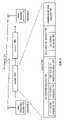
- FIG. 6illustrates the frame 126 in greater detail.
- the 1 st preamble segment 128includes the 1 st training sequence 134 , the 2 nd training sequence 136 and a signal field.
- the 1 st training sequence 134includes 10 short training sequences that utilize only a portion of the sub-carriers of the particular channel.
- the channel configurationmay be a 20 MHz channel bandwidth with 64 sub-carriers.
- the 1 st training sequence 134may only use 12 of the 52 data sub-carriers to convey the corresponding short training sequence.
- the 2 training sequence 136includes 2 long training sequences that may utilize 52 of the 52 data sub-carriers of a 20 MHz, 64 sub-carrier channel.
- the signal fieldincludes a guard interval (GI) and includes 24 bits of information.
- GIguard interval
- the 1 st 4 bitscorrespond to the rate of the data transmission, the next bit indicates the high through-put channel indication 138 , the next 12 bits correspond to the length of the variable length data segment 132 , bit 17 corresponds to the parity of the data and the remaining 6 bits correspond to a signal tail.
- the receiving radiowill configure itself based on a default or 1 st channel configuration which may be the 20 MHz bandwidth channel utilizing 64 sub-carriers as currently defined in IEEE802.11a and/or g. If, however, the high throughput channel indication 138 is set, and the receiver is capable of alternative channel configurations, it will begin interpreting the 2 nd preamble.
- the 2 nd preamble segment 130includes a channel format identification field and a plurality of training sequences 140 - 141 .
- the channel identification fieldmay include an additional 4-bits for rate information, 5-bits of channel configuration information, 12-bits to indicate a training matrix, and the remaining 3-bits may be reserved.
- the 24-bits of the channel format identification fieldmay be configured in a variety of ways to convey information to the receiving radio as to the bit rate of the high throughput data, the channel configuration on which the high throughput data will be conveyed, a diversity antenna arrangement, and a channel matrix to produce dual RF transmissions over a single channel.
- the receiving radioreconfigures itself based on the channel configuration and the data rate. Having reconfigured itself, the radio receives the 3 rd training sequence 140 through the nth training sequence 141 (where corresponds to the number of transmitting antennas) that utilizes a majority of the sub-carriers in accordance with the new channel configuration.
- the channel configurationswill be described in greater detail with reference to FIG. 7 .
- the rate bits in the 1 st preamble and 2 nd preamblemay be used in combination to provide 8-bits of rate information and/or may be used separately to provide, in the case of dual communications over a single path, to indicate the rates of the separate communications.
- the variable length data segment 132includes a plurality of data segments and associated guard intervals (GI).
- FIG. 7is a table illustrating the various channel configurations, which may be utilized to convey the high data throughput communications.
- the channel configuration tableincludes a column for the bits to index the particular channel configuration and configuration information, which includes channel bandwidth, number of sub-carriers per channel, rate interpretation (i.e., are the rate bits in each of the preamble sections to be combined or used separately) and space time coding (i.e., the number of channel paths that the particular RF channel is supporting).
- the channel bandwidth optionsthere are 3 channel bandwidth options, 10 MHz, 20 MHz, and 40 MHz, which may be used in any one of a number of frequency bands, including, but not limited to, 2.400-2.4835 GHz, 2.471-2.497 GHz, 5.15-5.25 GHz, 5.25-5.35 GHz, 5.47-5.725 GHz, 5.725 GHz-5.825 GHz, 4.9-5.3 GHz, and 5.85-5.925 GHz.
- the default operation of the wireless communication system in accordance with the present inventionwould operate as defined in IEEE 802.11a or g.
- the channel configuration for 802.11a and/or gincludes a 20 MHz channel bandwidth utilizing 64 sub-carriers where only 1 path is supported by the RF channel. Hence, the default channel configuration is not in the channel configuration information in the 2 nd preamble section.
- the rate on both channelsis the same corresponding to a rate interpretation of 0, which allows the eight bits (4 from the first preamble segment and 4 from the second preamble segment to be combined into one 8 bit code). If the rates for the 2 paths in space time coding are different, then the rate interpretation is 1. In this instance, the 4 bits of rate information in the 1 st preamble segment is used to indicate the rate of one of the channel paths and the 4 bits of rate information in the 2 nd preamble segment are used to indicate the rate of the other channel path.
- the 40 MHz channel bandwidthmay include 128 sub-carriers and support 1 or 2 paths per channel.
- the 10 MHz channel bandwidthhas 64 sub-carriers and may support 1 or 2 channel paths.
- FIG. 8is a diagram illustrating the 1 st training sequence 114 that is based on a 20 MHz channel and 64 sub-carriers per channel.
- the training sequenceis repeated twice and only uses 12 sub-carriers of the total 64 sub-carriers.
- each of the 12 sub-carrierscarries a symbol that is either 1+j or ⁇ 1 ⁇ j.
- the receiveris utilizing the 1 st training sequence 114 as a signal detect and once a possible signal is detected to adjust the gain settings within the receiver as well as to determine whether any diversity antenna selections have been made.
- the receiverduring the later portions of the 1 st training sequence 114 , may be performing coarse frequency adjustments, offset estimations, and/or timing synchronizations.
- FIG. 9is a diagram illustrating the 2 nd training sequence 116 that utilizes a 20 MHz channel bandwidth with 64 sub-carriers. Of the 64 sub-carriers, 53 are used in the 2 nd training sequence 116 . Each sub-carrier carries a symbol of +1 or ⁇ 1, except for the 0 th subcarrier, which carries a zero value. As the receiver is detecting the 2 nd training sequence 116 it may be performing channel and fine frequency adjustments and/or fine offset adjustments.
- FIG. 10is a diagram illustrating the 3 rd training sequence 120 of a 40 MHz channel utilizing single space time channel partitioning and including 128 subcarriers.
- the preambleuses 105-119 of the 128 sub-carriers wherein the symbols may be +1 or ⁇ 1 to convey the training sequence.
- the receiveris again performing channel and fine frequency adjustments corresponding to the 40 MHz channel 128 sub-carrier configuration of the channel.
- the receivermay be performing fine offset adjustments for the particular channel configuration.
- FIG. 11is a diagram of an alternate 3 rd training sequence 120 where the channel configuration is a 10 MHz channel having 64 sub-carriers.
- the 3 rd training sequence 120utilizes 53 sub-carriers of the 64 possible sub-carriers.
- the receiveris performing channel and fine frequency adjustments and/or fine offset adjustments for the 10 MHz bandwidth, 64 sub-carrier channel.
- the symbols utilized in the training sequencemay be +1 or ⁇ 1.
- FIG. 12is a diagram illustrating the 3 rd training sequence 120 where the channel selection is a 40 MHz channel, having 128 sub-carriers and utilizes space time encoding to produce 2 paths (path A and path B).
- each pathhas its own corresponding training sequence that utilizes 105 - 119 sub-carriers of the possible 128 sub-carriers.
- the symbols in each sub-carriermay be a +1 or ⁇ 1.
- the receiving radiomay be performing channel and fine frequency adjustments and/or fine offset adjustments for each path of the 40 MHz channel.
- the term “substantially” or “approximately”, as may be used herein,provides an industry-accepted tolerance to its corresponding term. Such an industry-accepted tolerance ranges from less than one percent to twenty percent and corresponds to, but is not limited to, component values, integrated circuit process variations, temperature variations, rise and fall times, and/or thermal noise.
- the term “operably coupled”, as may be used herein,includes direct coupling and indirect coupling via another component, element, circuit, or module where, for indirect coupling, the intervening component, element, circuit, or module does not modify the information of a signal but may adjust its current level, voltage level, and/or power level.
- inferred couplingincludes direct and indirect coupling between two elements in the same manner as “operably coupled”.
- the term “compares favorably”, as may be used herein,indicates that a comparison between two or more elements, items, signals, etc., provides a desired relationship. For example, when the desired relationship is that signal 1 has a greater magnitude than signal 2 , a favorable comparison may be achieved when the magnitude of signal 1 is greater than that of signal 2 or when the magnitude of signal 2 is less than that of signal 1 .
Landscapes
- Engineering & Computer Science (AREA)
- Signal Processing (AREA)
- Computer Networks & Wireless Communication (AREA)
- Power Engineering (AREA)
- Mobile Radio Communication Systems (AREA)
Abstract
Description
Claims (20)
Priority Applications (13)
| Application Number | Priority Date | Filing Date | Title |
|---|---|---|---|
| US10/778,751US7269430B2 (en) | 2003-11-24 | 2004-02-13 | Frame format for high data throughput wireless local area network transmissions |
| US10/973,611US7751429B2 (en) | 2004-02-13 | 2004-10-26 | Signaling format for WLANS |
| US10/973,612US7400643B2 (en) | 2004-02-13 | 2004-10-26 | Transmission of wide bandwidth signals in a network having legacy devices |
| EP04026610AEP1533963B1 (en) | 2003-11-24 | 2004-11-09 | Frame format for high data throughput wireless local area network transmissions |
| TW093136135ATWI303132B (en) | 2003-11-24 | 2004-11-24 | Frame format for high data throughput wireless local area |
| CN200410097703.7ACN1625180B (en) | 2003-11-24 | 2004-11-24 | Frame format for high data throughput wireless local area network transmissions |
| US11/056,155US7590189B2 (en) | 2004-02-13 | 2005-02-14 | Signaling format for wireless communications |
| US11/825,868US8406204B2 (en) | 2004-02-13 | 2007-07-10 | Transmission of wide bandwidth signals in a network having legacy devices |
| US11/833,429US7978729B2 (en) | 2003-11-24 | 2007-08-03 | High data throughput WLAN frame format |
| US12/559,824US8094749B2 (en) | 2004-02-13 | 2009-09-15 | Signaling format for wireless communications |
| US13/179,223US8897320B2 (en) | 2003-11-24 | 2011-07-08 | High data throughput WLAN frame format |
| US13/316,753US8630367B2 (en) | 2004-02-13 | 2011-12-12 | Signaling format for wireless communications |
| US13/622,718US8929317B2 (en) | 2004-02-13 | 2012-09-19 | Transmission of wide bandwidth signals in a network having legacy devices |
Applications Claiming Priority (2)
| Application Number | Priority Date | Filing Date | Title |
|---|---|---|---|
| US52452803P | 2003-11-24 | 2003-11-24 | |
| US10/778,751US7269430B2 (en) | 2003-11-24 | 2004-02-13 | Frame format for high data throughput wireless local area network transmissions |
Related Parent Applications (2)
| Application Number | Title | Priority Date | Filing Date |
|---|---|---|---|
| US10/778,754Continuation-In-PartUS7162204B2 (en) | 2003-07-18 | 2004-02-13 | Configurable spectral mask for use in a high data throughput wireless communication |
| US10/779,245Continuation-In-PartUS7539501B2 (en) | 2003-11-24 | 2004-02-13 | High data throughput wireless local area network receiver |
Related Child Applications (3)
| Application Number | Title | Priority Date | Filing Date |
|---|---|---|---|
| US10/778,754Continuation-In-PartUS7162204B2 (en) | 2003-07-18 | 2004-02-13 | Configurable spectral mask for use in a high data throughput wireless communication |
| US10/779,245Continuation-In-PartUS7539501B2 (en) | 2003-11-24 | 2004-02-13 | High data throughput wireless local area network receiver |
| US11/833,429ContinuationUS7978729B2 (en) | 2003-11-24 | 2007-08-03 | High data throughput WLAN frame format |
Publications (2)
| Publication Number | Publication Date |
|---|---|
| US20050113026A1 US20050113026A1 (en) | 2005-05-26 |
| US7269430B2true US7269430B2 (en) | 2007-09-11 |
Family
ID=34437383
Family Applications (3)
| Application Number | Title | Priority Date | Filing Date |
|---|---|---|---|
| US10/778,751Active2026-04-01US7269430B2 (en) | 2003-11-24 | 2004-02-13 | Frame format for high data throughput wireless local area network transmissions |
| US11/833,429Active2026-10-07US7978729B2 (en) | 2003-11-24 | 2007-08-03 | High data throughput WLAN frame format |
| US13/179,223Expired - LifetimeUS8897320B2 (en) | 2003-11-24 | 2011-07-08 | High data throughput WLAN frame format |
Family Applications After (2)
| Application Number | Title | Priority Date | Filing Date |
|---|---|---|---|
| US11/833,429Active2026-10-07US7978729B2 (en) | 2003-11-24 | 2007-08-03 | High data throughput WLAN frame format |
| US13/179,223Expired - LifetimeUS8897320B2 (en) | 2003-11-24 | 2011-07-08 | High data throughput WLAN frame format |
Country Status (4)
| Country | Link |
|---|---|
| US (3) | US7269430B2 (en) |
| EP (1) | EP1533963B1 (en) |
| CN (1) | CN1625180B (en) |
| TW (1) | TWI303132B (en) |
Cited By (30)
| Publication number | Priority date | Publication date | Assignee | Title |
|---|---|---|---|---|
| US20050170831A1 (en)* | 2004-02-04 | 2005-08-04 | Magee David P. | Frequency switched preamble design to minimize channel estimation time in MIMO communication systems |
| US20050276347A1 (en)* | 2004-06-10 | 2005-12-15 | Mujtaba Syed A | Method and apparatus for preamble training in a multiple antenna communication system |
| US20080310559A1 (en)* | 2007-06-15 | 2008-12-18 | Broadcom Corporation | Gain control for reduced interframe spacing (RIFS) |
| US20080310558A1 (en)* | 2007-06-15 | 2008-12-18 | Broadcom Corporation | Apparatus to reconfigure an 802.11a/n transceiver to support 802.11j/10 MHz mode of operation |
| US20080310487A1 (en)* | 2007-06-15 | 2008-12-18 | Broadcom Corporation | Single-chip wireless tranceiver |
| US20080309405A1 (en)* | 2007-06-15 | 2008-12-18 | Broadcom Corporation | Power Amplifier Pre-Distortion |
| US20090003308A1 (en)* | 2007-04-13 | 2009-01-01 | General Dynamics C4 Systems, Inc. | Methods and apparatus for generating synchronization/pilot sequences for embedding in wireless signals |
| US20090154427A1 (en)* | 2007-12-17 | 2009-06-18 | Electronics And Telecommunications Research Institute | Transmitter and receiver for high throughput wireless communication system using multiple antenna, method thereof, and digital intermediate frequency transmission signal processing method for the same |
| US20090225873A1 (en)* | 2008-03-05 | 2009-09-10 | Qualcomm Incorporated | Multiple Transmitter System and Method |
| US20100002672A1 (en)* | 2004-02-13 | 2010-01-07 | Broadcom Corporation | Signaling format for wireless communications |
| US20100040158A1 (en)* | 2008-08-15 | 2010-02-18 | Qualcomm Incorporated | Embedding information in an 802.11 signal field |
| US20100046656A1 (en)* | 2008-08-20 | 2010-02-25 | Qualcomm Incorporated | Preamble extensions |
| US20100172427A1 (en)* | 2008-03-19 | 2010-07-08 | General Dynamics C4 Systems, Inc. | Methods and apparatus for multiple-antenna communication of wireless signals with embedded synchronization/pilot sequences |
| US20100260246A1 (en)* | 2007-12-15 | 2010-10-14 | Electronics And Telecommunications Research Institute | Transmitter and receiver for giga-bps high-throughput wireless communication system with multiple antennas and multiple bands |
| US20100290449A1 (en)* | 2008-08-20 | 2010-11-18 | Qualcomm Incorporated | Preamble extensions |
| US20110075745A1 (en)* | 2009-09-25 | 2011-03-31 | General Dynamics C4 Systems, Inc. | Reducing transmitter-to-receiver non-linear distortion at a transmitter prior to estimating and cancelling known non-linear distortion at a receiver |
| US20110074506A1 (en)* | 2009-09-25 | 2011-03-31 | General Dynamics C4 Systems, Inc. | Cancelling non-linear power amplifier induced distortion from a received signal by moving incorrectly estimated constellation points |
| US20110110443A1 (en)* | 2009-11-06 | 2011-05-12 | Ui Kun Kwon | Data receiving apparatus for receiving data frame using constellation mapping scheme and data transmission apparatus for transmitting the data frame |
| US20110135023A1 (en)* | 2009-12-04 | 2011-06-09 | Samsung Electronics Co., Ltd. | Communication system and method using space division multi-user multiple input multiple output (sd-mimo) communication method |
| US20110149929A1 (en)* | 2008-04-14 | 2011-06-23 | General Dynamics C4 Systems, Inc. | Methods and apparatus for multiple-antenna communication of wireless signals with embedded pilot signals |
| US20110261803A1 (en)* | 2003-11-24 | 2011-10-27 | Broadcom Corporation | High data throughput wlan frame format |
| US8125965B1 (en)* | 2005-12-19 | 2012-02-28 | Kyocera Corporation | Wireless multi-mode system and method |
| US8306094B1 (en)* | 2004-05-19 | 2012-11-06 | Marvell International Ltd. | MIMO-OFDM receiver processing |
| US8472551B2 (en) | 2007-03-02 | 2013-06-25 | Qualcomm Incorporated | Three phase and polarity encoded serial interface |
| US20130343754A1 (en)* | 2012-06-21 | 2013-12-26 | Qualcomm Atheros, Inc. | Variable-length training fields in coaxial communications |
| US8996740B2 (en) | 2012-06-29 | 2015-03-31 | Qualcomm Incorporated | N-phase polarity output pin mode multiplexer |
| US20150195790A1 (en)* | 2014-01-06 | 2015-07-09 | Futurewei Technologies, Inc. | System and Method for Low Power Transmission |
| US9112815B2 (en) | 2012-06-15 | 2015-08-18 | Qualcomm Incorporated | Three-phase-polarity safe reverse link shutdown |
| US9231790B2 (en) | 2007-03-02 | 2016-01-05 | Qualcomm Incorporated | N-phase phase and polarity encoded serial interface |
| US9711041B2 (en) | 2012-03-16 | 2017-07-18 | Qualcomm Incorporated | N-phase polarity data transfer |
Families Citing this family (30)
| Publication number | Priority date | Publication date | Assignee | Title |
|---|---|---|---|---|
| US7440510B2 (en) | 2003-09-15 | 2008-10-21 | Intel Corporation | Multicarrier transmitter, multicarrier receiver, and methods for communicating multiple spatial signal streams |
| US7315577B2 (en) | 2003-09-15 | 2008-01-01 | Intel Corporation | Multiple antenna systems and method using high-throughput space-frequency block codes |
| US7324605B2 (en) | 2004-01-12 | 2008-01-29 | Intel Corporation | High-throughput multicarrier communication systems and methods for exchanging channel state information |
| US9203669B2 (en)* | 2005-02-02 | 2015-12-01 | Samsung Electronics Co., Ltd. | Apparatus and method using multiple modulation schemes in an OFDM/OFDMA wireless network |
| US7684779B2 (en)* | 2005-05-31 | 2010-03-23 | Broadcom Corporation | Wireless terminal baseband processor high speed turbo decoding module |
| KR100643299B1 (en)* | 2005-06-09 | 2006-11-10 | 삼성전자주식회사 | Method and apparatus for transmitting and receiving legacy data in high speed wireless network |
| CN102710373B (en)* | 2005-09-14 | 2015-04-22 | 美商内数位科技公司 | Access point, high-throughout station, and method of used in the same |
| US8155148B2 (en)* | 2005-09-27 | 2012-04-10 | Ciena Corporation | Telecommunications transport methods and systems for the transparent mapping/demapping of client data signals |
| CN1972269A (en)* | 2005-11-24 | 2007-05-30 | 松下电器产业株式会社 | Method for jointly producing and detecting multi-pilot frequency in multi-antenna communication system |
| KR100782844B1 (en)* | 2006-01-12 | 2007-12-06 | 삼성전자주식회사 | Method and apparatus for transmitting data frame using channel bonding in wireless LAN |
| US7440412B2 (en)* | 2006-03-13 | 2008-10-21 | Tzero Technologies, Inc. | Link quality prediction |
| JP4934723B2 (en)* | 2006-07-12 | 2012-05-16 | インテル・コーポレーション | System and method for determining predictable modulation and coding schemes |
| EP2168255B1 (en)* | 2007-06-11 | 2016-03-16 | Koninklijke Philips N.V. | A method, a transmitting station and a receiving station for analog beam forming |
| EP2019528A3 (en)* | 2007-07-12 | 2014-08-06 | Industrial Technology Research Institute | Method and module for constructing a frame structure in communication systems |
| KR101434176B1 (en)* | 2007-08-28 | 2014-09-30 | 삼성전자주식회사 | Access point and mobile station of wireless communication system and control method thereof |
| US9253742B1 (en)* | 2007-11-29 | 2016-02-02 | Qualcomm Incorporated | Fine timing for high throughput packets |
| US8072959B2 (en)* | 2008-03-06 | 2011-12-06 | Issc Technologies Corp. | Generating method for short training field in IEEE 802.11n communication systems |
| US20100067514A1 (en)* | 2008-09-15 | 2010-03-18 | Qualcomm Incorporated | Wireless communication systems with femto nodes |
| US8842604B2 (en)* | 2008-09-15 | 2014-09-23 | Qualcomm Incorporated | Wireless communication systems with femto nodes |
| US8542706B2 (en)* | 2008-12-08 | 2013-09-24 | Qualcomm Incorporated | Method and apparatus related to packet fragmentation and reconstruction |
| US9503931B2 (en)* | 2009-08-12 | 2016-11-22 | Qualcomm Incorporated | Enhancements to the MU-MIMO VHT preamble to enable mode detection |
| GB201016407D0 (en)* | 2010-09-29 | 2010-11-10 | Samsung Electronics Co Ltd | Frame structure and signalling for digital broadcasting system |
| EP2652944A4 (en) | 2010-12-13 | 2014-08-27 | Samsung Electronics Co Ltd | METHOD AND APPARATUS FOR TRANSMITTING / RECEIVING A DATA STREAM IN A BROADCASTING SYSTEM |
| US9191923B2 (en)* | 2011-04-15 | 2015-11-17 | Qualcomm Incorporated | Systems and methods for range extension of wireless communication in sub gigahertz bands |
| US9281928B2 (en) | 2011-04-18 | 2016-03-08 | Broadcom Corporation | Range extension within single user, multiple user, multiple access, and/or MIMO wireless communications |
| US9048994B2 (en)* | 2011-04-18 | 2015-06-02 | Broadcom Corporation | Downclocking and/or adaptive sub-carriers for single user, multiple user, multiple access, and/or MIMO wireless communications |
| EP3086521B1 (en) | 2014-01-28 | 2020-03-25 | Huawei Technologies Co., Ltd. | Data transmission method and communication device |
| CN106416107B (en)* | 2014-05-26 | 2019-08-02 | 夏普株式会社 | Wireless transmitter, wireless receiver, and communication method |
| US10499346B2 (en)* | 2018-04-03 | 2019-12-03 | Cypress Semiconductor Corporation | System and method extending range of a wireless network |
| GB2577741B (en)* | 2018-10-05 | 2022-07-27 | Airspan Ip Holdco Llc | An apparatus and method for configuring a communication link |
Family Cites Families (6)
| Publication number | Priority date | Publication date | Assignee | Title |
|---|---|---|---|---|
| US7035661B1 (en)* | 1996-10-11 | 2006-04-25 | Arraycomm, Llc. | Power control with signal quality estimation for smart antenna communication systems |
| US6563858B1 (en)* | 1998-01-16 | 2003-05-13 | Intersil Americas Inc. | Method of performing antenna diversity in spread spectrum in wireless local area network |
| CN1452343A (en)* | 2002-04-15 | 2003-10-29 | 威盛电子股份有限公司 | Radio local network signal transmission method and related apparatus |
| AU2003250416A1 (en)* | 2002-08-13 | 2004-02-25 | Koninklijke Philips Electronics N.V. | Joint channel and noise variance estimation in a wideband ofdm system |
| US7269430B2 (en)* | 2003-11-24 | 2007-09-11 | Broadcom Corporation | Frame format for high data throughput wireless local area network transmissions |
| US7324605B2 (en)* | 2004-01-12 | 2008-01-29 | Intel Corporation | High-throughput multicarrier communication systems and methods for exchanging channel state information |
- 2004
- 2004-02-13USUS10/778,751patent/US7269430B2/enactiveActive
- 2004-11-09EPEP04026610Apatent/EP1533963B1/ennot_activeExpired - Lifetime
- 2004-11-24TWTW093136135Apatent/TWI303132B/ennot_activeIP Right Cessation
- 2004-11-24CNCN200410097703.7Apatent/CN1625180B/ennot_activeExpired - Lifetime
- 2007
- 2007-08-03USUS11/833,429patent/US7978729B2/enactiveActive
- 2011
- 2011-07-08USUS13/179,223patent/US8897320B2/ennot_activeExpired - Lifetime
Non-Patent Citations (5)
| Title |
|---|
| Erik G. Larsson and Jia Li, "Preamble Design for Multiple-Antenna OFDM-Based WLANs With Null Subcarriers," IEEE Signal Processing Letters, vol. 8, No. 11, Nov. 2001, pp. 285-288. |
| Jianhua Liu, Jian Li and Petre Stoica, "A MIMO System With Backward Compatibility For OFDM Based WLANS," 2003 4th IEEE Workshop on Signal Processing Advances In Wireless Communications, 0-7803-7858-X/03, pp. 130-134. |
| Takeshi Onizawa, Masato Mizoguchi, Masahiro Morikura and Toshiaki Tanaka, "A Fast Synchronization Scheme of OFDM Signals for High-Rate Wireless LAN," IEICE Trans. Commun., vol. E82-B. No. 2, Feb. 199, pp. 455-463. |
| XP-002236904, Part 11: Wireless LAN Medium Access Control (MAC) and Physical Laer (PHY) specifications: High-speed Physical Layer in the 5 GHZ Band, Sponsor: LAN/MAN Standards Committee of the IEEE Computer Society, IEEE Std 802. 11a-1999, Sep. 1999, pp. 1-53. |
| XP-002298432, 802.11gTM, IEEE Standard for Information Technology, Part 11: Wireless LAN Medium Access Control (MAC) and Physical Layer (PHY) Specifications, Amendment 4: Further Data Rate Extension in the 2.4 GHz Band, IEEE Computer Society, Jun. 2003, pp. 1-78. |
Cited By (76)
| Publication number | Priority date | Publication date | Assignee | Title |
|---|---|---|---|---|
| US20110261803A1 (en)* | 2003-11-24 | 2011-10-27 | Broadcom Corporation | High data throughput wlan frame format |
| US8897320B2 (en)* | 2003-11-24 | 2014-11-25 | Broadcom Corporation | High data throughput WLAN frame format |
| US7457232B2 (en)* | 2004-02-04 | 2008-11-25 | Texas Instruments Incorporated | Frequency switched preamble design to minimize channel estimation time in MIMO communications systems |
| US20050170831A1 (en)* | 2004-02-04 | 2005-08-04 | Magee David P. | Frequency switched preamble design to minimize channel estimation time in MIMO communication systems |
| US8094749B2 (en) | 2004-02-13 | 2012-01-10 | Broadcom Corporation | Signaling format for wireless communications |
| US8630367B2 (en) | 2004-02-13 | 2014-01-14 | Broadcom Corporation | Signaling format for wireless communications |
| US20100002672A1 (en)* | 2004-02-13 | 2010-01-07 | Broadcom Corporation | Signaling format for wireless communications |
| US8634451B1 (en) | 2004-05-19 | 2014-01-21 | Marvell International Ltd. | MIMO-OFDM receiver processing |
| US9094116B1 (en) | 2004-05-19 | 2015-07-28 | Marvell International Ltd. | MIMO-OFDM receiver processing |
| US8306094B1 (en)* | 2004-05-19 | 2012-11-06 | Marvell International Ltd. | MIMO-OFDM receiver processing |
| US20050276347A1 (en)* | 2004-06-10 | 2005-12-15 | Mujtaba Syed A | Method and apparatus for preamble training in a multiple antenna communication system |
| US8619907B2 (en)* | 2004-06-10 | 2013-12-31 | Agere Systems, LLC | Method and apparatus for preamble training in a multiple antenna communication system |
| US8125965B1 (en)* | 2005-12-19 | 2012-02-28 | Kyocera Corporation | Wireless multi-mode system and method |
| US8472551B2 (en) | 2007-03-02 | 2013-06-25 | Qualcomm Incorporated | Three phase and polarity encoded serial interface |
| US9455850B2 (en) | 2007-03-02 | 2016-09-27 | Qualcomm Incorporated | Three phase and polarity encoded serial interface |
| US9231790B2 (en) | 2007-03-02 | 2016-01-05 | Qualcomm Incorporated | N-phase phase and polarity encoded serial interface |
| US10033560B2 (en) | 2007-03-02 | 2018-07-24 | Qualcomm Incorporated | Three phase and polarity encoded serial interface |
| US9083598B2 (en) | 2007-03-02 | 2015-07-14 | Qualcomm Incorporated | Three phase and polarity encoded serial interface |
| US9680666B2 (en) | 2007-03-02 | 2017-06-13 | Qualcomm Incorporated | N-phase phase and polarity encoded serial interface |
| US9948485B2 (en) | 2007-03-02 | 2018-04-17 | Qualcomm Incorporated | Three phase and polarity encoded serial interface |
| US9998300B2 (en) | 2007-03-02 | 2018-06-12 | Qualcomm Incorporated | N-phase phase and polarity encoded serial interface |
| US20090052561A1 (en)* | 2007-04-13 | 2009-02-26 | General Dynamics C4 Systems, Inc. | Methods and apparatus for generating and communicating wireless signals having pilot signals with variable pilot signal parameters |
| US8131218B2 (en) | 2007-04-13 | 2012-03-06 | General Dynamics C4 Systems, Inc. | Methods and apparatus for wirelessly communicating signals that include embedded synchronization/pilot sequences |
| US8358644B2 (en) | 2007-04-13 | 2013-01-22 | General Dynamics C4 Systems, Inc. | Methods and apparatus for generating synchronization/pilot sequences for embedding in wireless signals |
| US20090011722A1 (en)* | 2007-04-13 | 2009-01-08 | General Dynamics C4 Systems, Inc. | Methods and apparatus for wirelessly communicating signals that include embedded synchronization/pilot sequences |
| US20090003308A1 (en)* | 2007-04-13 | 2009-01-01 | General Dynamics C4 Systems, Inc. | Methods and apparatus for generating synchronization/pilot sequences for embedding in wireless signals |
| US8098713B2 (en) | 2007-04-13 | 2012-01-17 | General Dynamics C4 Systems | Methods and apparatus for generating and communicating wireless signals having pilot signals with variable pilot signal parameters |
| US8369388B2 (en) | 2007-06-15 | 2013-02-05 | Broadcom Corporation | Single-chip wireless tranceiver |
| US8634501B2 (en) | 2007-06-15 | 2014-01-21 | Broadcom Corporation | Carrier selection for multiple antennas |
| US20080310559A1 (en)* | 2007-06-15 | 2008-12-18 | Broadcom Corporation | Gain control for reduced interframe spacing (RIFS) |
| US8618880B2 (en) | 2007-06-15 | 2013-12-31 | Broadcom Corporation | Power amplifier pre-distortion |
| US8194808B2 (en) | 2007-06-15 | 2012-06-05 | Broadcom Corporation | Carrier selection for multiple antennas |
| US8199857B2 (en) | 2007-06-15 | 2012-06-12 | Broadcom Corporation | Apparatus to reconfigure an 802.11a/n transceiver to support 802.11j/10 MHz mode of operation |
| US8294516B2 (en) | 2007-06-15 | 2012-10-23 | Broadcom Corporation | Power amplifier pre-distortion |
| US8116408B2 (en) | 2007-06-15 | 2012-02-14 | Broadcom Corporation | Gain control for reduced interframe spacing (RIFS) |
| US20080310336A1 (en)* | 2007-06-15 | 2008-12-18 | Broadcom Corporation | Dynamic receiver filter adjustment across preamble and information payload |
| US20080310487A1 (en)* | 2007-06-15 | 2008-12-18 | Broadcom Corporation | Single-chip wireless tranceiver |
| US20080310558A1 (en)* | 2007-06-15 | 2008-12-18 | Broadcom Corporation | Apparatus to reconfigure an 802.11a/n transceiver to support 802.11j/10 MHz mode of operation |
| US20080309405A1 (en)* | 2007-06-15 | 2008-12-18 | Broadcom Corporation | Power Amplifier Pre-Distortion |
| US9112481B2 (en) | 2007-06-15 | 2015-08-18 | Broadcom Corporation | Carrier selection for multiple antennas |
| US20080310557A1 (en)* | 2007-06-15 | 2008-12-18 | Broadcom Corporation | Carrier selection for multiple antennas |
| US8396102B2 (en)* | 2007-12-15 | 2013-03-12 | Electronics And Telecommunications Research Institute | Transmitter and receiver for giga-bps high-throughput wireless communication system with multiple antennas and multiple bands |
| US20100260246A1 (en)* | 2007-12-15 | 2010-10-14 | Electronics And Telecommunications Research Institute | Transmitter and receiver for giga-bps high-throughput wireless communication system with multiple antennas and multiple bands |
| US8422465B2 (en)* | 2007-12-17 | 2013-04-16 | Electronics And Telecommunications Research Institute | Transmitter and receiver for high throughput wireless communication system using multiple antenna, method thereof, and digital intermediate frequency transmission signal processing method for the same |
| US20090154427A1 (en)* | 2007-12-17 | 2009-06-18 | Electronics And Telecommunications Research Institute | Transmitter and receiver for high throughput wireless communication system using multiple antenna, method thereof, and digital intermediate frequency transmission signal processing method for the same |
| US8848810B2 (en) | 2008-03-05 | 2014-09-30 | Qualcomm Incorporated | Multiple transmitter system and method |
| US20090225873A1 (en)* | 2008-03-05 | 2009-09-10 | Qualcomm Incorporated | Multiple Transmitter System and Method |
| US20100172427A1 (en)* | 2008-03-19 | 2010-07-08 | General Dynamics C4 Systems, Inc. | Methods and apparatus for multiple-antenna communication of wireless signals with embedded synchronization/pilot sequences |
| US8379752B2 (en) | 2008-03-19 | 2013-02-19 | General Dynamics C4 Systems, Inc. | Methods and apparatus for multiple-antenna communication of wireless signals with embedded synchronization/pilot sequences |
| US8331420B2 (en) | 2008-04-14 | 2012-12-11 | General Dynamics C4 Systems, Inc. | Methods and apparatus for multiple-antenna communication of wireless signals with embedded pilot signals |
| US20110149929A1 (en)* | 2008-04-14 | 2011-06-23 | General Dynamics C4 Systems, Inc. | Methods and apparatus for multiple-antenna communication of wireless signals with embedded pilot signals |
| US20100040158A1 (en)* | 2008-08-15 | 2010-02-18 | Qualcomm Incorporated | Embedding information in an 802.11 signal field |
| US8351519B2 (en) | 2008-08-15 | 2013-01-08 | Qualcomm Incorporated | Embedding information in an 802.11 signal field |
| US20100290449A1 (en)* | 2008-08-20 | 2010-11-18 | Qualcomm Incorporated | Preamble extensions |
| US9231806B2 (en) | 2008-08-20 | 2016-01-05 | Qualcomm Incorporated | Preamble extensions |
| US20100046656A1 (en)* | 2008-08-20 | 2010-02-25 | Qualcomm Incorporated | Preamble extensions |
| US8744009B2 (en) | 2009-09-25 | 2014-06-03 | General Dynamics C4 Systems, Inc. | Reducing transmitter-to-receiver non-linear distortion at a transmitter prior to estimating and cancelling known non-linear distortion at a receiver |
| US20110074506A1 (en)* | 2009-09-25 | 2011-03-31 | General Dynamics C4 Systems, Inc. | Cancelling non-linear power amplifier induced distortion from a received signal by moving incorrectly estimated constellation points |
| US8355466B2 (en) | 2009-09-25 | 2013-01-15 | General Dynamics C4 Systems, Inc. | Cancelling non-linear power amplifier induced distortion from a received signal by moving incorrectly estimated constellation points |
| US20110075745A1 (en)* | 2009-09-25 | 2011-03-31 | General Dynamics C4 Systems, Inc. | Reducing transmitter-to-receiver non-linear distortion at a transmitter prior to estimating and cancelling known non-linear distortion at a receiver |
| US8509329B2 (en) | 2009-11-06 | 2013-08-13 | Samsung Electronics Co., Ltd. | Data receiving apparatus for receiving data frame using constellation mapping scheme and data transmission apparatus for transmitting the date frame |
| US20110110443A1 (en)* | 2009-11-06 | 2011-05-12 | Ui Kun Kwon | Data receiving apparatus for receiving data frame using constellation mapping scheme and data transmission apparatus for transmitting the data frame |
| US9071296B2 (en) | 2009-12-04 | 2015-06-30 | Samsung Electronics Co., Ltd. | Communication system and method using space division multi-user multiple input multiple output (SD-MIMO) communication method |
| US8767858B2 (en) | 2009-12-04 | 2014-07-01 | Samsung Electronics Co., Ltd. | Communication system and method using space division multi-user multiple input multiple output (SD-MIMO) communication method |
| US8929482B2 (en) | 2009-12-04 | 2015-01-06 | Samsung Electronics Co., Ltd. | Communication system and method using space division multi-user multiple input multiple output (SD-MIMO) communication method |
| US20110135023A1 (en)* | 2009-12-04 | 2011-06-09 | Samsung Electronics Co., Ltd. | Communication system and method using space division multi-user multiple input multiple output (sd-mimo) communication method |
| US9806776B2 (en) | 2009-12-04 | 2017-10-31 | Samsung Electronics Co., Ltd. | Communication system and method using space division multi-user multiple input multiple output (SD-MIMO) communication method |
| US10134272B2 (en) | 2012-03-16 | 2018-11-20 | Qualcomm Incorporated | N-phase polarity data transfer |
| US9711041B2 (en) | 2012-03-16 | 2017-07-18 | Qualcomm Incorporated | N-phase polarity data transfer |
| US9112815B2 (en) | 2012-06-15 | 2015-08-18 | Qualcomm Incorporated | Three-phase-polarity safe reverse link shutdown |
| US20130343754A1 (en)* | 2012-06-21 | 2013-12-26 | Qualcomm Atheros, Inc. | Variable-length training fields in coaxial communications |
| US8750281B2 (en)* | 2012-06-21 | 2014-06-10 | Qualcomm Incorporated | Variable-length training fields in coaxial communications |
| US9143362B2 (en) | 2012-06-29 | 2015-09-22 | Qualcomm Incorporated | N-phase polarity output pin mode multiplexer |
| US8996740B2 (en) | 2012-06-29 | 2015-03-31 | Qualcomm Incorporated | N-phase polarity output pin mode multiplexer |
| US20150195790A1 (en)* | 2014-01-06 | 2015-07-09 | Futurewei Technologies, Inc. | System and Method for Low Power Transmission |
| US10142936B2 (en)* | 2014-01-06 | 2018-11-27 | Futurewei Technologies, Inc. | System and method for low power transmission |
Also Published As
| Publication number | Publication date |
|---|---|
| EP1533963A2 (en) | 2005-05-25 |
| US20050113026A1 (en) | 2005-05-26 |
| EP1533963B1 (en) | 2011-10-26 |
| US20070268881A1 (en) | 2007-11-22 |
| TW200529683A (en) | 2005-09-01 |
| CN1625180B (en) | 2010-08-11 |
| EP1533963A3 (en) | 2007-04-11 |
| US20110261803A1 (en) | 2011-10-27 |
| TWI303132B (en) | 2008-11-11 |
| US8897320B2 (en) | 2014-11-25 |
| US7978729B2 (en) | 2011-07-12 |
| CN1625180A (en) | 2005-06-08 |
Similar Documents
| Publication | Publication Date | Title |
|---|---|---|
| US7269430B2 (en) | Frame format for high data throughput wireless local area network transmissions | |
| US9247439B2 (en) | High data throughput wireless local area network receiver | |
| US9344535B2 (en) | Multiple protocol wireless communications in a WLAN | |
| EP1533910B1 (en) | Configurable spectral mask for use in a high data throughput wireless communication | |
| US8929317B2 (en) | Transmission of wide bandwidth signals in a network having legacy devices | |
| US8891642B2 (en) | Mixed mode preamble for MIMO wireless communications | |
| US8068550B2 (en) | Initiation of a MIMO communication | |
| US9516483B2 (en) | Wireless communication between stations of differing protocols | |
| US8107442B2 (en) | Master/slave oscillation production and distribution in a multiple RF transceiver system supporting MIMO operations |
Legal Events
| Date | Code | Title | Description |
|---|---|---|---|
| AS | Assignment | Owner name:BROADCOM CORPORATION, CALIFORNIA Free format text:ASSIGNMENT OF ASSIGNORS INTEREST;ASSIGNORS:MOORTI, R. TUSHAR;HANSEN, CHRISTOPHER J.;TRACHEWSKY, JASON A.;REEL/FRAME:014994/0252 Effective date:20040211 | |
| FEPP | Fee payment procedure | Free format text:PAYOR NUMBER ASSIGNED (ORIGINAL EVENT CODE: ASPN); ENTITY STATUS OF PATENT OWNER: LARGE ENTITY | |
| STCF | Information on status: patent grant | Free format text:PATENTED CASE | |
| FPAY | Fee payment | Year of fee payment:4 | |
| FPAY | Fee payment | Year of fee payment:8 | |
| AS | Assignment | Owner name:BANK OF AMERICA, N.A., AS COLLATERAL AGENT, NORTH CAROLINA Free format text:PATENT SECURITY AGREEMENT;ASSIGNOR:BROADCOM CORPORATION;REEL/FRAME:037806/0001 Effective date:20160201 Owner name:BANK OF AMERICA, N.A., AS COLLATERAL AGENT, NORTH Free format text:PATENT SECURITY AGREEMENT;ASSIGNOR:BROADCOM CORPORATION;REEL/FRAME:037806/0001 Effective date:20160201 | |
| AS | Assignment | Owner name:AVAGO TECHNOLOGIES GENERAL IP (SINGAPORE) PTE. LTD., SINGAPORE Free format text:ASSIGNMENT OF ASSIGNORS INTEREST;ASSIGNOR:BROADCOM CORPORATION;REEL/FRAME:041706/0001 Effective date:20170120 Owner name:AVAGO TECHNOLOGIES GENERAL IP (SINGAPORE) PTE. LTD Free format text:ASSIGNMENT OF ASSIGNORS INTEREST;ASSIGNOR:BROADCOM CORPORATION;REEL/FRAME:041706/0001 Effective date:20170120 | |
| AS | Assignment | Owner name:BROADCOM CORPORATION, CALIFORNIA Free format text:TERMINATION AND RELEASE OF SECURITY INTEREST IN PATENTS;ASSIGNOR:BANK OF AMERICA, N.A., AS COLLATERAL AGENT;REEL/FRAME:041712/0001 Effective date:20170119 | |
| AS | Assignment | Owner name:AVAGO TECHNOLOGIES INTERNATIONAL SALES PTE. LIMITE Free format text:MERGER;ASSIGNOR:AVAGO TECHNOLOGIES GENERAL IP (SINGAPORE) PTE. LTD.;REEL/FRAME:047196/0097 Effective date:20180509 | |
| AS | Assignment | Owner name:AVAGO TECHNOLOGIES INTERNATIONAL SALES PTE. LIMITE Free format text:CORRECTIVE ASSIGNMENT TO CORRECT THE EXECUTION DATE PREVIOUSLY RECORDED AT REEL: 047196 FRAME: 0097. ASSIGNOR(S) HEREBY CONFIRMS THE MERGER;ASSIGNOR:AVAGO TECHNOLOGIES GENERAL IP (SINGAPORE) PTE. LTD.;REEL/FRAME:048555/0510 Effective date:20180905 | |
| MAFP | Maintenance fee payment | Free format text:PAYMENT OF MAINTENANCE FEE, 12TH YEAR, LARGE ENTITY (ORIGINAL EVENT CODE: M1553); ENTITY STATUS OF PATENT OWNER: LARGE ENTITY Year of fee payment:12 |