US7269328B2 - Brightness enhancement film having a light-guiding structure - Google Patents
Brightness enhancement film having a light-guiding structureInfo
- Publication number
- US7269328B2 US7269328B2US11/162,703US16270305AUS7269328B2US 7269328 B2US7269328 B2US 7269328B2US 16270305 AUS16270305 AUS 16270305AUS 7269328 B2US7269328 B2US 7269328B2
- Authority
- US
- United States
- Prior art keywords
- light
- brightness enhancement
- enhancement film
- substrate
- guiding structure
- Prior art date
- Legal status (The legal status is an assumption and is not a legal conclusion. Google has not performed a legal analysis and makes no representation as to the accuracy of the status listed.)
- Active, expires
Links
- 239000000758substrateSubstances0.000claimsabstractdescription71
- 230000003014reinforcing effectEffects0.000claimsdescription62
- 239000012780transparent materialSubstances0.000claimsdescription34
- 239000002131composite materialSubstances0.000claimsdescription13
- 239000000853adhesiveSubstances0.000claimsdescription4
- 230000001070adhesive effectEffects0.000claimsdescription4
- 230000000149penetrating effectEffects0.000claimsdescription4
- 239000004925Acrylic resinSubstances0.000claimsdescription2
- 229920000178Acrylic resinPolymers0.000claimsdescription2
- 239000004593EpoxySubstances0.000claimsdescription2
- 239000011248coating agentSubstances0.000claimsdescription2
- 238000000576coating methodMethods0.000claimsdescription2
- 238000000151depositionMethods0.000claimsdescription2
- 230000008021depositionEffects0.000claimsdescription2
- 238000005240physical vapour depositionMethods0.000claimsdescription2
- 238000004544sputter depositionMethods0.000claimsdescription2
- XMQFTWRPUQYINF-UHFFFAOYSA-Nbensulfuron-methylChemical compoundCOC(=O)C1=CC=CC=C1CS(=O)(=O)NC(=O)NC1=NC(OC)=CC(OC)=N1XMQFTWRPUQYINF-UHFFFAOYSA-N0.000claims1
- 239000010410layerSubstances0.000description162
- 238000005299abrasionMethods0.000description16
- 230000002708enhancing effectEffects0.000description13
- 238000004519manufacturing processMethods0.000description6
- 239000002245particleSubstances0.000description3
- 239000000463materialSubstances0.000description2
- 238000010276constructionMethods0.000description1
- 230000007812deficiencyEffects0.000description1
- 239000004973liquid crystal related substanceSubstances0.000description1
- 238000000034methodMethods0.000description1
- 238000012986modificationMethods0.000description1
- 230000004048modificationEffects0.000description1
- 230000002265preventionEffects0.000description1
- 238000007790scrapingMethods0.000description1
- 239000002356single layerSubstances0.000description1
- 230000002269spontaneous effectEffects0.000description1
Images


Classifications
- G—PHYSICS
- G02—OPTICS
- G02B—OPTICAL ELEMENTS, SYSTEMS OR APPARATUS
- G02B6/00—Light guides; Structural details of arrangements comprising light guides and other optical elements, e.g. couplings
- G02B6/0001—Light guides; Structural details of arrangements comprising light guides and other optical elements, e.g. couplings specially adapted for lighting devices or systems
- G02B6/0011—Light guides; Structural details of arrangements comprising light guides and other optical elements, e.g. couplings specially adapted for lighting devices or systems the light guides being planar or of plate-like form
- G02B6/0033—Means for improving the coupling-out of light from the light guide
- G02B6/005—Means for improving the coupling-out of light from the light guide provided by one optical element, or plurality thereof, placed on the light output side of the light guide
- G02B6/0053—Prismatic sheet or layer; Brightness enhancement element, sheet or layer
- G—PHYSICS
- G02—OPTICS
- G02B—OPTICAL ELEMENTS, SYSTEMS OR APPARATUS
- G02B6/00—Light guides; Structural details of arrangements comprising light guides and other optical elements, e.g. couplings
- G02B6/0001—Light guides; Structural details of arrangements comprising light guides and other optical elements, e.g. couplings specially adapted for lighting devices or systems
- G02B6/0011—Light guides; Structural details of arrangements comprising light guides and other optical elements, e.g. couplings specially adapted for lighting devices or systems the light guides being planar or of plate-like form
- G02B6/0033—Means for improving the coupling-out of light from the light guide
- G02B6/0035—Means for improving the coupling-out of light from the light guide provided on the surface of the light guide or in the bulk of it
- G02B6/0036—2-D arrangement of prisms, protrusions, indentations or roughened surfaces
- G—PHYSICS
- G02—OPTICS
- G02B—OPTICAL ELEMENTS, SYSTEMS OR APPARATUS
- G02B6/00—Light guides; Structural details of arrangements comprising light guides and other optical elements, e.g. couplings
- G02B6/0001—Light guides; Structural details of arrangements comprising light guides and other optical elements, e.g. couplings specially adapted for lighting devices or systems
- G02B6/0011—Light guides; Structural details of arrangements comprising light guides and other optical elements, e.g. couplings specially adapted for lighting devices or systems the light guides being planar or of plate-like form
- G02B6/0033—Means for improving the coupling-out of light from the light guide
- G02B6/0035—Means for improving the coupling-out of light from the light guide provided on the surface of the light guide or in the bulk of it
- G02B6/0038—Linear indentations or grooves, e.g. arc-shaped grooves or meandering grooves, extending over the full length or width of the light guide
- Y—GENERAL TAGGING OF NEW TECHNOLOGICAL DEVELOPMENTS; GENERAL TAGGING OF CROSS-SECTIONAL TECHNOLOGIES SPANNING OVER SEVERAL SECTIONS OF THE IPC; TECHNICAL SUBJECTS COVERED BY FORMER USPC CROSS-REFERENCE ART COLLECTIONS [XRACs] AND DIGESTS
- Y10—TECHNICAL SUBJECTS COVERED BY FORMER USPC
- Y10S—TECHNICAL SUBJECTS COVERED BY FORMER USPC CROSS-REFERENCE ART COLLECTIONS [XRACs] AND DIGESTS
- Y10S385/00—Optical waveguides
- Y10S385/901—Illuminating or display apparatus
Definitions
- the present inventionintends to provide a brightness enhancement film having a plurality of light-refracting microstructures and a light-guiding layer, wherein the light-refracting microstructures are arranged on a light incident surface while the light-guiding layer is arranged on a light emission surface.
- the light-refracting microstructurecan refract light, and subsequently, the light-guiding layer can guide the refracted light for providing homogeneous light in such a way as to mitigate and overcome the above problem.
- the reinforcing layer 23covers the light emission surface 21 b of the light-guiding layer 21 to form a composite reinforced laminate.
- the micro-hemispheres 22 of the light-refracting microstructure layerare used to refract light, and arranged to form a plurality of hexagonal units in a hexagonal manner such that each of the micro-hemispheres 22 has six of the adjacent micro-hemispheres 22 .
- the micro-hemispheres 22serve to circularly refract light projecting from the light source in two dimensions for enhancing brightness of light.
- the reinforcing layer 23can perform a relatively high degree of hardness so that the brightness enhancement film 2 has a high degree of warpage resistance and abrasion resistance.
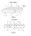
- the meandering surfaces 42 a , 42 bserve to refract light projecting from the light source in two dimensions for enhancing brightness of light and attenuating the morie phenomenon. Additionally, the reinforcing layer 43 can perform a relatively high degree of hardness so that the brightness enhancement film 4 has a high degree of warpage resistance and abrasion resistance.
- the brightness enhancement film 4having a light-guiding structure in accordance with a ninth embodiment of the present invention is illustrated.
- the brightness enhancement film 4includes a light-guiding layer 41 , curved prism units 42 and a reinforcing layer 43 which are stacked to constitute the brightness enhancement film 4 .
- the light-guiding layer 41has a light incident surface 41 a and a light emission surface 41 b opposite thereto.
- the light-refracting microstructure layerconsists of the curved prism units 42 which are raised on the light incident surface 41 a of the light-guiding layer 41 and parallel to each other.
- the reinforcing layer 43covers the light emission surface 41 b of the light-guiding layer 41 to form a composite reinforced laminate.
Landscapes
- Physics & Mathematics (AREA)
- General Physics & Mathematics (AREA)
- Optics & Photonics (AREA)
- Planar Illumination Modules (AREA)
- Optical Integrated Circuits (AREA)
- Optical Elements Other Than Lenses (AREA)
- Liquid Crystal (AREA)
Abstract
Description
Claims (32)
Applications Claiming Priority (2)
| Application Number | Priority Date | Filing Date | Title |
|---|---|---|---|
| TW094131444ATWI391711B (en) | 2005-09-13 | 2005-09-13 | Brightness enhancement film having a light-guiding layer |
| TW94131444 | 2005-09-13 |
Publications (2)
| Publication Number | Publication Date |
|---|---|
| US20070058920A1 US20070058920A1 (en) | 2007-03-15 |
| US7269328B2true US7269328B2 (en) | 2007-09-11 |
Family
ID=37855192
Family Applications (1)
| Application Number | Title | Priority Date | Filing Date |
|---|---|---|---|
| US11/162,703Active2025-11-18US7269328B2 (en) | 2005-09-13 | 2005-09-20 | Brightness enhancement film having a light-guiding structure |
Country Status (3)
| Country | Link |
|---|---|
| US (1) | US7269328B2 (en) |
| JP (1) | JP3117156U (en) |
| TW (1) | TWI391711B (en) |
Cited By (43)
| Publication number | Priority date | Publication date | Assignee | Title |
|---|---|---|---|---|
| US20070291369A1 (en)* | 2006-06-19 | 2007-12-20 | Takashi Shimura | Optical element, lighting device, and liquid crystal display device |
| US20100103351A1 (en)* | 2007-05-25 | 2010-04-29 | Cheil Indusstries | Prism sheet having wet-out property and lcd back light unit thereby |
| US7815326B2 (en) | 2002-06-06 | 2010-10-19 | Donnelly Corporation | Interior rearview mirror system |
| US7822543B2 (en) | 2000-03-02 | 2010-10-26 | Donnelly Corporation | Video display system for vehicle |
| US7821697B2 (en) | 1994-05-05 | 2010-10-26 | Donnelly Corporation | Exterior reflective mirror element for a vehicular rearview mirror assembly |
| US7826123B2 (en) | 2002-09-20 | 2010-11-02 | Donnelly Corporation | Vehicular interior electrochromic rearview mirror assembly |
| US7832882B2 (en) | 2002-06-06 | 2010-11-16 | Donnelly Corporation | Information mirror system |
| US7855755B2 (en) | 2005-11-01 | 2010-12-21 | Donnelly Corporation | Interior rearview mirror assembly with display |
| US7859737B2 (en) | 2002-09-20 | 2010-12-28 | Donnelly Corporation | Interior rearview mirror system for a vehicle |
| US7864399B2 (en) | 2002-09-20 | 2011-01-04 | Donnelly Corporation | Reflective mirror assembly |
| US7871169B2 (en) | 1994-05-05 | 2011-01-18 | Donnelly Corporation | Vehicular signal mirror |
| US7888629B2 (en) | 1998-01-07 | 2011-02-15 | Donnelly Corporation | Vehicular accessory mounting system with a forwardly-viewing camera |
| US7898398B2 (en) | 1997-08-25 | 2011-03-01 | Donnelly Corporation | Interior mirror system |
| US7898719B2 (en) | 2003-10-02 | 2011-03-01 | Donnelly Corporation | Rearview mirror assembly for vehicle |
| WO2011025963A1 (en) | 2009-08-28 | 2011-03-03 | 3M Innovative Properties Company | Optical device with antistatic coating |
| US7906756B2 (en) | 2002-05-03 | 2011-03-15 | Donnelly Corporation | Vehicle rearview mirror system |
| US7914188B2 (en) | 1997-08-25 | 2011-03-29 | Donnelly Corporation | Interior rearview mirror system for a vehicle |
| US7916009B2 (en) | 1998-01-07 | 2011-03-29 | Donnelly Corporation | Accessory mounting system suitable for use in a vehicle |
| WO2011038279A1 (en) | 2009-09-24 | 2011-03-31 | 3M Innovative Properties Company | Web conveyance method and apparatus using same |
| US7926960B2 (en) | 1999-11-24 | 2011-04-19 | Donnelly Corporation | Interior rearview mirror system for vehicle |
| WO2011053709A2 (en) | 2009-10-30 | 2011-05-05 | 3M Innovative Properties Company | Optical device with antistatic property |
| US8019505B2 (en) | 2003-10-14 | 2011-09-13 | Donnelly Corporation | Vehicle information display |
| US8044776B2 (en) | 2000-03-02 | 2011-10-25 | Donnelly Corporation | Rear vision system for vehicle |
| WO2011130951A1 (en) | 2010-04-23 | 2011-10-27 | 上海凯鑫森产业投资控股有限公司 | Optical compound sheet for backlight module |
| US8072318B2 (en) | 2001-01-23 | 2011-12-06 | Donnelly Corporation | Video mirror system for vehicle |
| US8083386B2 (en) | 2001-01-23 | 2011-12-27 | Donnelly Corporation | Interior rearview mirror assembly with display device |
| US8154418B2 (en) | 2008-03-31 | 2012-04-10 | Magna Mirrors Of America, Inc. | Interior rearview mirror system |
| US8194133B2 (en) | 2000-03-02 | 2012-06-05 | Donnelly Corporation | Vehicular video mirror system |
| US8288711B2 (en) | 1998-01-07 | 2012-10-16 | Donnelly Corporation | Interior rearview mirror system with forwardly-viewing camera and a control |
| US8294975B2 (en) | 1997-08-25 | 2012-10-23 | Donnelly Corporation | Automotive rearview mirror assembly |
| TWI382247B (en)* | 2008-12-31 | 2013-01-11 | Eternal Chemical Co Ltd | Backlight module |
| US8462204B2 (en) | 1995-05-22 | 2013-06-11 | Donnelly Corporation | Vehicular vision system |
| WO2013102022A1 (en) | 2011-12-30 | 2013-07-04 | 3M Innovative Properties Company | Vacuum effector and method of use |
| US8503062B2 (en) | 2005-05-16 | 2013-08-06 | Donnelly Corporation | Rearview mirror element assembly for vehicle |
| US8525703B2 (en) | 1998-04-08 | 2013-09-03 | Donnelly Corporation | Interior rearview mirror system |
| US8742047B2 (en) | 2009-08-28 | 2014-06-03 | 3M Innovative Properties Company | Polymerizable ionic liquid comprising multifunctional cation and antistatic coatings |
| US8816029B2 (en) | 2009-08-28 | 2014-08-26 | 3M Innovative Properties Company | Compositions and articles comprising polymerizable ionic liquid mixture, and methods of curing |
| US8853338B2 (en) | 2009-12-22 | 2014-10-07 | 3M Innovative Properties Company | Curable dental compositions and articles comprising polymerizable ionic liquids |
| US9019091B2 (en) | 1999-11-24 | 2015-04-28 | Donnelly Corporation | Interior rearview mirror system |
| US20150185400A1 (en)* | 2013-12-27 | 2015-07-02 | Lg Innotek Co., Ltd. | Optical member and lighting device using the same |
| US20150219827A1 (en)* | 2014-02-05 | 2015-08-06 | Lg Innotek Co., Ltd. | Optical member and lighting device using the same |
| US9487144B2 (en) | 2008-10-16 | 2016-11-08 | Magna Mirrors Of America, Inc. | Interior mirror assembly with display |
| US9915762B2 (en) | 2012-08-21 | 2018-03-13 | 3M Innovative Properties Company | Articles with binder-deficient slip coating and method for making same |
Families Citing this family (5)
| Publication number | Priority date | Publication date | Assignee | Title |
|---|---|---|---|---|
| TWI363195B (en)* | 2006-04-14 | 2012-05-01 | Sony Corp | Optical sheet, back-light device and liquid crystal display device |
| US20090214828A1 (en)* | 2008-02-26 | 2009-08-27 | Vicki Herzl Watkins | Blunt tip prism film and methods for making the same |
| EP2268717B1 (en)* | 2008-03-28 | 2017-09-06 | 3M Innovative Properties Company | Thick polyester films for optical articles and optical articles |
| KR100952327B1 (en) | 2009-12-18 | 2010-04-09 | 김성진 | Cover for led lamp and manufacturing method thereby |
| TWI641893B (en)* | 2017-06-02 | 2018-11-21 | 奇菱光電股份有限公司 | Liquid crystal display apparatus, and polarized light guide plate and the manufacturing method thereof |
Citations (19)
| Publication number | Priority date | Publication date | Assignee | Title |
|---|---|---|---|---|
| US5245454A (en)* | 1991-12-31 | 1993-09-14 | At&T Bell Laboratories | Lcd display with microtextured back reflector and method for making same |
| US5626800A (en) | 1995-02-03 | 1997-05-06 | Minnesota Mining And Manufacturing Company | Prevention of groove tip deformation in brightness enhancement film |
| US6277471B1 (en)* | 1999-06-18 | 2001-08-21 | Shih Chieh Tang | Brightness enhancement film |
| US6280063B1 (en) | 1997-05-09 | 2001-08-28 | 3M Innovative Properties Company | Brightness enhancement article |
| US6339458B1 (en) | 1999-09-10 | 2002-01-15 | Enplas Corporation | Light guide plate, surface light source device of side light type and liquid crystal display |
| US6356389B1 (en) | 1999-11-12 | 2002-03-12 | Reflexite Corporation | Subwavelength optical microstructure light collimating films |
| US6354709B1 (en) | 1998-02-18 | 2002-03-12 | 3M Innovative Properties Company | Optical film |
| US6581286B2 (en)* | 2000-04-05 | 2003-06-24 | 3M Innovative Properties Company | Method of making tool to produce optical film |
| US6669350B2 (en) | 2000-12-14 | 2003-12-30 | Mitsubish Rayon Co., Ltd. | Planar light source system and light deflecting device therefor |
| US6707611B2 (en) | 1999-10-08 | 2004-03-16 | 3M Innovative Properties Company | Optical film with variable angle prisms |
| US6759113B1 (en)* | 2003-03-24 | 2004-07-06 | Shih-Chieh Tang | Uniform curved surface structure of a brightness unit for a brightness enhancement film |
| US20050007513A1 (en)* | 2003-03-05 | 2005-01-13 | Lee Jeong-Hwan | Optical sheet and LCD apparatus using the same |
| US6845212B2 (en)* | 1999-10-08 | 2005-01-18 | 3M Innovative Properties Company | Optical element having programmed optical structures |
| US6862141B2 (en)* | 2002-05-20 | 2005-03-01 | General Electric Company | Optical substrate and method of making |
| US6951400B2 (en)* | 2002-12-04 | 2005-10-04 | General Electric Company | High index coated light management films |
| US20050237641A1 (en)* | 2004-04-22 | 2005-10-27 | Shih-Chieh Tang | Brightness enhancement film having curved prism units |
| US6981792B2 (en)* | 2002-12-06 | 2006-01-03 | Alps Electric Co., Ltd. | Backlight device and liquid crystal display device |
| US7090389B2 (en)* | 1999-02-23 | 2006-08-15 | Solid State Opto Limited | Method of selecting a light redirecting film |
| US20070002471A1 (en)* | 2005-06-30 | 2007-01-04 | Efun Technology Co., Ltd. | Brightness enhancement film having a reinforcing structure |
Family Cites Families (2)
| Publication number | Priority date | Publication date | Assignee | Title |
|---|---|---|---|---|
| TWI230834B (en)* | 2003-12-31 | 2005-04-11 | Ind Tech Res Inst | High-transmissivity polarizing module constituted with sub-wavelength structure |
| TWI231866B (en)* | 2003-12-31 | 2005-05-01 | Ritdisplay Corp | Reinforced polarization substrate |
- 2005
- 2005-09-13TWTW094131444Apatent/TWI391711B/enactive
- 2005-09-20USUS11/162,703patent/US7269328B2/enactiveActive
- 2005-09-29JPJP2005008001Upatent/JP3117156U/ennot_activeExpired - Fee Related
Patent Citations (19)
| Publication number | Priority date | Publication date | Assignee | Title |
|---|---|---|---|---|
| US5245454A (en)* | 1991-12-31 | 1993-09-14 | At&T Bell Laboratories | Lcd display with microtextured back reflector and method for making same |
| US5626800A (en) | 1995-02-03 | 1997-05-06 | Minnesota Mining And Manufacturing Company | Prevention of groove tip deformation in brightness enhancement film |
| US6280063B1 (en) | 1997-05-09 | 2001-08-28 | 3M Innovative Properties Company | Brightness enhancement article |
| US6354709B1 (en) | 1998-02-18 | 2002-03-12 | 3M Innovative Properties Company | Optical film |
| US7090389B2 (en)* | 1999-02-23 | 2006-08-15 | Solid State Opto Limited | Method of selecting a light redirecting film |
| US6277471B1 (en)* | 1999-06-18 | 2001-08-21 | Shih Chieh Tang | Brightness enhancement film |
| US6339458B1 (en) | 1999-09-10 | 2002-01-15 | Enplas Corporation | Light guide plate, surface light source device of side light type and liquid crystal display |
| US6845212B2 (en)* | 1999-10-08 | 2005-01-18 | 3M Innovative Properties Company | Optical element having programmed optical structures |
| US6707611B2 (en) | 1999-10-08 | 2004-03-16 | 3M Innovative Properties Company | Optical film with variable angle prisms |
| US6356389B1 (en) | 1999-11-12 | 2002-03-12 | Reflexite Corporation | Subwavelength optical microstructure light collimating films |
| US6581286B2 (en)* | 2000-04-05 | 2003-06-24 | 3M Innovative Properties Company | Method of making tool to produce optical film |
| US6669350B2 (en) | 2000-12-14 | 2003-12-30 | Mitsubish Rayon Co., Ltd. | Planar light source system and light deflecting device therefor |
| US6862141B2 (en)* | 2002-05-20 | 2005-03-01 | General Electric Company | Optical substrate and method of making |
| US6951400B2 (en)* | 2002-12-04 | 2005-10-04 | General Electric Company | High index coated light management films |
| US6981792B2 (en)* | 2002-12-06 | 2006-01-03 | Alps Electric Co., Ltd. | Backlight device and liquid crystal display device |
| US20050007513A1 (en)* | 2003-03-05 | 2005-01-13 | Lee Jeong-Hwan | Optical sheet and LCD apparatus using the same |
| US6759113B1 (en)* | 2003-03-24 | 2004-07-06 | Shih-Chieh Tang | Uniform curved surface structure of a brightness unit for a brightness enhancement film |
| US20050237641A1 (en)* | 2004-04-22 | 2005-10-27 | Shih-Chieh Tang | Brightness enhancement film having curved prism units |
| US20070002471A1 (en)* | 2005-06-30 | 2007-01-04 | Efun Technology Co., Ltd. | Brightness enhancement film having a reinforcing structure |
Cited By (154)
| Publication number | Priority date | Publication date | Assignee | Title |
|---|---|---|---|---|
| US8164817B2 (en) | 1994-05-05 | 2012-04-24 | Donnelly Corporation | Method of forming a mirrored bent cut glass shape for vehicular exterior rearview mirror assembly |
| US8511841B2 (en) | 1994-05-05 | 2013-08-20 | Donnelly Corporation | Vehicular blind spot indicator mirror |
| US7821697B2 (en) | 1994-05-05 | 2010-10-26 | Donnelly Corporation | Exterior reflective mirror element for a vehicular rearview mirror assembly |
| US7871169B2 (en) | 1994-05-05 | 2011-01-18 | Donnelly Corporation | Vehicular signal mirror |
| US8559093B2 (en) | 1995-04-27 | 2013-10-15 | Donnelly Corporation | Electrochromic mirror reflective element for vehicular rearview mirror assembly |
| US8462204B2 (en) | 1995-05-22 | 2013-06-11 | Donnelly Corporation | Vehicular vision system |
| US8842176B2 (en) | 1996-05-22 | 2014-09-23 | Donnelly Corporation | Automatic vehicle exterior light control |
| US8309907B2 (en) | 1997-08-25 | 2012-11-13 | Donnelly Corporation | Accessory system suitable for use in a vehicle and accommodating a rain sensor |
| US7914188B2 (en) | 1997-08-25 | 2011-03-29 | Donnelly Corporation | Interior rearview mirror system for a vehicle |
| US8100568B2 (en) | 1997-08-25 | 2012-01-24 | Donnelly Corporation | Interior rearview mirror system for a vehicle |
| US8063753B2 (en) | 1997-08-25 | 2011-11-22 | Donnelly Corporation | Interior rearview mirror system |
| US8267559B2 (en) | 1997-08-25 | 2012-09-18 | Donnelly Corporation | Interior rearview mirror assembly for a vehicle |
| US7898398B2 (en) | 1997-08-25 | 2011-03-01 | Donnelly Corporation | Interior mirror system |
| US8779910B2 (en) | 1997-08-25 | 2014-07-15 | Donnelly Corporation | Interior rearview mirror system |
| US8610992B2 (en) | 1997-08-25 | 2013-12-17 | Donnelly Corporation | Variable transmission window |
| US8294975B2 (en) | 1997-08-25 | 2012-10-23 | Donnelly Corporation | Automotive rearview mirror assembly |
| US8288711B2 (en) | 1998-01-07 | 2012-10-16 | Donnelly Corporation | Interior rearview mirror system with forwardly-viewing camera and a control |
| US7888629B2 (en) | 1998-01-07 | 2011-02-15 | Donnelly Corporation | Vehicular accessory mounting system with a forwardly-viewing camera |
| US8134117B2 (en) | 1998-01-07 | 2012-03-13 | Donnelly Corporation | Vehicular having a camera, a rain sensor and a single-ball interior electrochromic mirror assembly attached at an attachment element |
| US7916009B2 (en) | 1998-01-07 | 2011-03-29 | Donnelly Corporation | Accessory mounting system suitable for use in a vehicle |
| US8325028B2 (en) | 1998-01-07 | 2012-12-04 | Donnelly Corporation | Interior rearview mirror system |
| US7994471B2 (en) | 1998-01-07 | 2011-08-09 | Donnelly Corporation | Interior rearview mirror system with forwardly-viewing camera |
| US8094002B2 (en) | 1998-01-07 | 2012-01-10 | Donnelly Corporation | Interior rearview mirror system |
| US8525703B2 (en) | 1998-04-08 | 2013-09-03 | Donnelly Corporation | Interior rearview mirror system |
| US9481306B2 (en) | 1998-04-08 | 2016-11-01 | Donnelly Corporation | Automotive communication system |
| US9221399B2 (en) | 1998-04-08 | 2015-12-29 | Magna Mirrors Of America, Inc. | Automotive communication system |
| US8884788B2 (en) | 1998-04-08 | 2014-11-11 | Donnelly Corporation | Automotive communication system |
| US7926960B2 (en) | 1999-11-24 | 2011-04-19 | Donnelly Corporation | Interior rearview mirror system for vehicle |
| US10144355B2 (en) | 1999-11-24 | 2018-12-04 | Donnelly Corporation | Interior rearview mirror system for vehicle |
| US9278654B2 (en) | 1999-11-24 | 2016-03-08 | Donnelly Corporation | Interior rearview mirror system for vehicle |
| US8162493B2 (en) | 1999-11-24 | 2012-04-24 | Donnelly Corporation | Interior rearview mirror assembly for vehicle |
| US9376061B2 (en) | 1999-11-24 | 2016-06-28 | Donnelly Corporation | Accessory system of a vehicle |
| US9019091B2 (en) | 1999-11-24 | 2015-04-28 | Donnelly Corporation | Interior rearview mirror system |
| US8121787B2 (en) | 2000-03-02 | 2012-02-21 | Donnelly Corporation | Vehicular video mirror system |
| US9783114B2 (en) | 2000-03-02 | 2017-10-10 | Donnelly Corporation | Vehicular video mirror system |
| US8095310B2 (en) | 2000-03-02 | 2012-01-10 | Donnelly Corporation | Video mirror system for a vehicle |
| US8427288B2 (en) | 2000-03-02 | 2013-04-23 | Donnelly Corporation | Rear vision system for a vehicle |
| US8676491B2 (en) | 2000-03-02 | 2014-03-18 | Magna Electronics Inc. | Driver assist system for vehicle |
| US8908039B2 (en) | 2000-03-02 | 2014-12-09 | Donnelly Corporation | Vehicular video mirror system |
| US10239457B2 (en) | 2000-03-02 | 2019-03-26 | Magna Electronics Inc. | Vehicular vision system |
| US9014966B2 (en) | 2000-03-02 | 2015-04-21 | Magna Electronics Inc. | Driver assist system for vehicle |
| US10179545B2 (en) | 2000-03-02 | 2019-01-15 | Magna Electronics Inc. | Park-aid system for vehicle |
| US10131280B2 (en) | 2000-03-02 | 2018-11-20 | Donnelly Corporation | Vehicular video mirror system |
| US10053013B2 (en) | 2000-03-02 | 2018-08-21 | Magna Electronics Inc. | Vision system for vehicle |
| US9809168B2 (en) | 2000-03-02 | 2017-11-07 | Magna Electronics Inc. | Driver assist system for vehicle |
| US8179236B2 (en) | 2000-03-02 | 2012-05-15 | Donnelly Corporation | Video mirror system suitable for use in a vehicle |
| US8194133B2 (en) | 2000-03-02 | 2012-06-05 | Donnelly Corporation | Vehicular video mirror system |
| US9809171B2 (en) | 2000-03-02 | 2017-11-07 | Magna Electronics Inc. | Vision system for vehicle |
| US8543330B2 (en) | 2000-03-02 | 2013-09-24 | Donnelly Corporation | Driver assist system for vehicle |
| US8271187B2 (en) | 2000-03-02 | 2012-09-18 | Donnelly Corporation | Vehicular video mirror system |
| US9019090B2 (en) | 2000-03-02 | 2015-04-28 | Magna Electronics Inc. | Vision system for vehicle |
| US7822543B2 (en) | 2000-03-02 | 2010-10-26 | Donnelly Corporation | Video display system for vehicle |
| US8000894B2 (en) | 2000-03-02 | 2011-08-16 | Donnelly Corporation | Vehicular wireless communication system |
| US8044776B2 (en) | 2000-03-02 | 2011-10-25 | Donnelly Corporation | Rear vision system for vehicle |
| US9315151B2 (en) | 2000-03-02 | 2016-04-19 | Magna Electronics Inc. | Driver assist system for vehicle |
| US9352623B2 (en) | 2001-01-23 | 2016-05-31 | Magna Electronics Inc. | Trailer hitching aid system for vehicle |
| US9694749B2 (en) | 2001-01-23 | 2017-07-04 | Magna Electronics Inc. | Trailer hitching aid system for vehicle |
| US8072318B2 (en) | 2001-01-23 | 2011-12-06 | Donnelly Corporation | Video mirror system for vehicle |
| US8083386B2 (en) | 2001-01-23 | 2011-12-27 | Donnelly Corporation | Interior rearview mirror assembly with display device |
| US10272839B2 (en) | 2001-01-23 | 2019-04-30 | Magna Electronics Inc. | Rear seat occupant monitoring system for vehicle |
| US8653959B2 (en) | 2001-01-23 | 2014-02-18 | Donnelly Corporation | Video mirror system for a vehicle |
| US8654433B2 (en) | 2001-01-23 | 2014-02-18 | Magna Mirrors Of America, Inc. | Rearview mirror assembly for vehicle |
| US8304711B2 (en) | 2002-05-03 | 2012-11-06 | Donnelly Corporation | Vehicle rearview mirror system |
| US7906756B2 (en) | 2002-05-03 | 2011-03-15 | Donnelly Corporation | Vehicle rearview mirror system |
| US8106347B2 (en) | 2002-05-03 | 2012-01-31 | Donnelly Corporation | Vehicle rearview mirror system |
| US7918570B2 (en) | 2002-06-06 | 2011-04-05 | Donnelly Corporation | Vehicular interior rearview information mirror system |
| US8608327B2 (en) | 2002-06-06 | 2013-12-17 | Donnelly Corporation | Automatic compass system for vehicle |
| US8465163B2 (en) | 2002-06-06 | 2013-06-18 | Donnelly Corporation | Interior rearview mirror system |
| US8282226B2 (en) | 2002-06-06 | 2012-10-09 | Donnelly Corporation | Interior rearview mirror system |
| US7815326B2 (en) | 2002-06-06 | 2010-10-19 | Donnelly Corporation | Interior rearview mirror system |
| US8465162B2 (en) | 2002-06-06 | 2013-06-18 | Donnelly Corporation | Vehicular interior rearview mirror system |
| US8177376B2 (en) | 2002-06-06 | 2012-05-15 | Donnelly Corporation | Vehicular interior rearview mirror system |
| US7832882B2 (en) | 2002-06-06 | 2010-11-16 | Donnelly Corporation | Information mirror system |
| US8047667B2 (en) | 2002-06-06 | 2011-11-01 | Donnelly Corporation | Vehicular interior rearview mirror system |
| US10029616B2 (en) | 2002-09-20 | 2018-07-24 | Donnelly Corporation | Rearview mirror assembly for vehicle |
| US8727547B2 (en) | 2002-09-20 | 2014-05-20 | Donnelly Corporation | Variable reflectance mirror reflective element for exterior mirror assembly |
| US7826123B2 (en) | 2002-09-20 | 2010-11-02 | Donnelly Corporation | Vehicular interior electrochromic rearview mirror assembly |
| US9341914B2 (en) | 2002-09-20 | 2016-05-17 | Donnelly Corporation | Variable reflectance mirror reflective element for exterior mirror assembly |
| US9090211B2 (en) | 2002-09-20 | 2015-07-28 | Donnelly Corporation | Variable reflectance mirror reflective element for exterior mirror assembly |
| US9073491B2 (en) | 2002-09-20 | 2015-07-07 | Donnelly Corporation | Exterior rearview mirror assembly |
| US10661716B2 (en) | 2002-09-20 | 2020-05-26 | Donnelly Corporation | Vehicular exterior electrically variable reflectance mirror reflective element assembly |
| US9545883B2 (en) | 2002-09-20 | 2017-01-17 | Donnelly Corporation | Exterior rearview mirror assembly |
| US8400704B2 (en) | 2002-09-20 | 2013-03-19 | Donnelly Corporation | Interior rearview mirror system for a vehicle |
| US8277059B2 (en) | 2002-09-20 | 2012-10-02 | Donnelly Corporation | Vehicular electrochromic interior rearview mirror assembly |
| US10363875B2 (en) | 2002-09-20 | 2019-07-30 | Donnelly Corportion | Vehicular exterior electrically variable reflectance mirror reflective element assembly |
| US8335032B2 (en) | 2002-09-20 | 2012-12-18 | Donnelly Corporation | Reflective mirror assembly |
| US9878670B2 (en) | 2002-09-20 | 2018-01-30 | Donnelly Corporation | Variable reflectance mirror reflective element for exterior mirror assembly |
| US8797627B2 (en) | 2002-09-20 | 2014-08-05 | Donnelly Corporation | Exterior rearview mirror assembly |
| US10538202B2 (en) | 2002-09-20 | 2020-01-21 | Donnelly Corporation | Method of manufacturing variable reflectance mirror reflective element for exterior mirror assembly |
| US8506096B2 (en) | 2002-09-20 | 2013-08-13 | Donnelly Corporation | Variable reflectance mirror reflective element for exterior mirror assembly |
| US7864399B2 (en) | 2002-09-20 | 2011-01-04 | Donnelly Corporation | Reflective mirror assembly |
| US8228588B2 (en) | 2002-09-20 | 2012-07-24 | Donnelly Corporation | Interior rearview mirror information display system for a vehicle |
| US7859737B2 (en) | 2002-09-20 | 2010-12-28 | Donnelly Corporation | Interior rearview mirror system for a vehicle |
| US8705161B2 (en) | 2003-10-02 | 2014-04-22 | Donnelly Corporation | Method of manufacturing a reflective element for a vehicular rearview mirror assembly |
| US7898719B2 (en) | 2003-10-02 | 2011-03-01 | Donnelly Corporation | Rearview mirror assembly for vehicle |
| US8379289B2 (en) | 2003-10-02 | 2013-02-19 | Donnelly Corporation | Rearview mirror assembly for vehicle |
| US8179586B2 (en) | 2003-10-02 | 2012-05-15 | Donnelly Corporation | Rearview mirror assembly for vehicle |
| US8355839B2 (en) | 2003-10-14 | 2013-01-15 | Donnelly Corporation | Vehicle vision system with night vision function |
| US8095260B1 (en) | 2003-10-14 | 2012-01-10 | Donnelly Corporation | Vehicle information display |
| US8170748B1 (en) | 2003-10-14 | 2012-05-01 | Donnelly Corporation | Vehicle information display system |
| US8019505B2 (en) | 2003-10-14 | 2011-09-13 | Donnelly Corporation | Vehicle information display |
| US8577549B2 (en) | 2003-10-14 | 2013-11-05 | Donnelly Corporation | Information display system for a vehicle |
| US8282253B2 (en) | 2004-11-22 | 2012-10-09 | Donnelly Corporation | Mirror reflective element sub-assembly for exterior rearview mirror of a vehicle |
| US8503062B2 (en) | 2005-05-16 | 2013-08-06 | Donnelly Corporation | Rearview mirror element assembly for vehicle |
| US8833987B2 (en) | 2005-09-14 | 2014-09-16 | Donnelly Corporation | Mirror reflective element sub-assembly for exterior rearview mirror of a vehicle |
| US9694753B2 (en) | 2005-09-14 | 2017-07-04 | Magna Mirrors Of America, Inc. | Mirror reflective element sub-assembly for exterior rearview mirror of a vehicle |
| US11072288B2 (en) | 2005-09-14 | 2021-07-27 | Magna Mirrors Of America, Inc. | Vehicular exterior rearview mirror assembly with blind spot indicator element |
| US10150417B2 (en) | 2005-09-14 | 2018-12-11 | Magna Mirrors Of America, Inc. | Mirror reflective element sub-assembly for exterior rearview mirror of a vehicle |
| US10308186B2 (en) | 2005-09-14 | 2019-06-04 | Magna Mirrors Of America, Inc. | Vehicular exterior rearview mirror assembly with blind spot indicator |
| US9045091B2 (en) | 2005-09-14 | 2015-06-02 | Donnelly Corporation | Mirror reflective element sub-assembly for exterior rearview mirror of a vehicle |
| US9758102B1 (en) | 2005-09-14 | 2017-09-12 | Magna Mirrors Of America, Inc. | Mirror reflective element sub-assembly for exterior rearview mirror of a vehicle |
| US10829053B2 (en) | 2005-09-14 | 2020-11-10 | Magna Mirrors Of America, Inc. | Vehicular exterior rearview mirror assembly with blind spot indicator |
| US11285879B2 (en) | 2005-09-14 | 2022-03-29 | Magna Mirrors Of America, Inc. | Vehicular exterior rearview mirror assembly with blind spot indicator element |
| US11124121B2 (en) | 2005-11-01 | 2021-09-21 | Magna Electronics Inc. | Vehicular vision system |
| US11970113B2 (en) | 2005-11-01 | 2024-04-30 | Magna Electronics Inc. | Vehicular vision system |
| US7855755B2 (en) | 2005-11-01 | 2010-12-21 | Donnelly Corporation | Interior rearview mirror assembly with display |
| US20070291369A1 (en)* | 2006-06-19 | 2007-12-20 | Takashi Shimura | Optical element, lighting device, and liquid crystal display device |
| US8384847B2 (en)* | 2007-05-25 | 2013-02-26 | Cheil Industries, Inc. | Prism sheet having wet-out property and LCD back light unit thereby |
| US20100103351A1 (en)* | 2007-05-25 | 2010-04-29 | Cheil Indusstries | Prism sheet having wet-out property and lcd back light unit thereby |
| US8508383B2 (en) | 2008-03-31 | 2013-08-13 | Magna Mirrors of America, Inc | Interior rearview mirror system |
| US8154418B2 (en) | 2008-03-31 | 2012-04-10 | Magna Mirrors Of America, Inc. | Interior rearview mirror system |
| US10175477B2 (en) | 2008-03-31 | 2019-01-08 | Magna Mirrors Of America, Inc. | Display system for vehicle |
| US9487144B2 (en) | 2008-10-16 | 2016-11-08 | Magna Mirrors Of America, Inc. | Interior mirror assembly with display |
| US11021107B2 (en) | 2008-10-16 | 2021-06-01 | Magna Mirrors Of America, Inc. | Vehicular interior rearview mirror system with display |
| US10583782B2 (en) | 2008-10-16 | 2020-03-10 | Magna Mirrors Of America, Inc. | Interior mirror assembly with display |
| US11577652B2 (en) | 2008-10-16 | 2023-02-14 | Magna Mirrors Of America, Inc. | Vehicular video camera display system |
| US12054098B2 (en) | 2008-10-16 | 2024-08-06 | Magna Mirrors Of America, Inc. | Vehicular video camera display system |
| US11807164B2 (en) | 2008-10-16 | 2023-11-07 | Magna Mirrors Of America, Inc. | Vehicular video camera display system |
| US12391183B2 (en) | 2008-10-16 | 2025-08-19 | Magna Mirrors Of America, Inc. | Vehicular video camera display system |
| TWI382247B (en)* | 2008-12-31 | 2013-01-11 | Eternal Chemical Co Ltd | Backlight module |
| US8816029B2 (en) | 2009-08-28 | 2014-08-26 | 3M Innovative Properties Company | Compositions and articles comprising polymerizable ionic liquid mixture, and methods of curing |
| US8742047B2 (en) | 2009-08-28 | 2014-06-03 | 3M Innovative Properties Company | Polymerizable ionic liquid comprising multifunctional cation and antistatic coatings |
| US9127101B2 (en) | 2009-08-28 | 2015-09-08 | 3M Innovative Properties Company | Compositions and articles comprising polymerizable ionic liquid mixture, and methods of curing |
| US11807795B2 (en) | 2009-08-28 | 2023-11-07 | 3M Innovative Properties Company | Optical device with antistatic coating |
| US9458327B2 (en) | 2009-08-28 | 2016-10-04 | 3M Innovative Properties Company | Polymerizable ionic liquid comprising multifunctional cation and antistatic coatings |
| WO2011025963A1 (en) | 2009-08-28 | 2011-03-03 | 3M Innovative Properties Company | Optical device with antistatic coating |
| US10486932B2 (en) | 2009-09-24 | 2019-11-26 | 3M Innovative Properties Company | Web conveyance apparatus |
| WO2011038284A1 (en) | 2009-09-24 | 2011-03-31 | 3M Innovative Properties Company | Method for making engagement cover for rollers for web conveyance apparatus |
| US9845216B2 (en) | 2009-09-24 | 2017-12-19 | 3M Innovative Properties Company | Web conveyance method and apparatus using same |
| US8784940B2 (en) | 2009-09-24 | 2014-07-22 | 3M Innovative Properties Company | Method for making engagement cover for rollers for web conveyance apparatus |
| WO2011038279A1 (en) | 2009-09-24 | 2011-03-31 | 3M Innovative Properties Company | Web conveyance method and apparatus using same |
| WO2011053709A2 (en) | 2009-10-30 | 2011-05-05 | 3M Innovative Properties Company | Optical device with antistatic property |
| US11111392B2 (en) | 2009-10-30 | 2021-09-07 | 3M Innovative Properties Company | Optical device with antistatic property |
| US8853338B2 (en) | 2009-12-22 | 2014-10-07 | 3M Innovative Properties Company | Curable dental compositions and articles comprising polymerizable ionic liquids |
| US9168206B2 (en) | 2009-12-22 | 2015-10-27 | 3M Innovative Properties Company | Curable dental compositions and articles comprising polymerizable ionic liquids |
| WO2011130951A1 (en) | 2010-04-23 | 2011-10-27 | 上海凯鑫森产业投资控股有限公司 | Optical compound sheet for backlight module |
| US9115863B2 (en) | 2010-04-23 | 2015-08-25 | Ccs(Shanghai) Functional Films Industry Co., Ltd. | Optical compound sheet for backlight module |
| WO2013102022A1 (en) | 2011-12-30 | 2013-07-04 | 3M Innovative Properties Company | Vacuum effector and method of use |
| US9915762B2 (en) | 2012-08-21 | 2018-03-13 | 3M Innovative Properties Company | Articles with binder-deficient slip coating and method for making same |
| US10317607B2 (en) | 2013-12-27 | 2019-06-11 | Lg Innotek Co., Ltd. | Optical member having three-dimensional effect forming portion and multiple effect forming portion and lighting device using the same |
| US9766390B2 (en)* | 2013-12-27 | 2017-09-19 | Lg Innotek Co., Ltd. | Optical member having three-dimensional effect forming portion and multiple effect forming portion and lighting device using the same |
| US20150185400A1 (en)* | 2013-12-27 | 2015-07-02 | Lg Innotek Co., Ltd. | Optical member and lighting device using the same |
| US10151869B2 (en)* | 2014-02-05 | 2018-12-11 | Lg Innotek Co., Ltd. | Optical member and lighting device using the same |
| US20150219827A1 (en)* | 2014-02-05 | 2015-08-06 | Lg Innotek Co., Ltd. | Optical member and lighting device using the same |
Also Published As
| Publication number | Publication date |
|---|---|
| TWI391711B (en) | 2013-04-01 |
| JP3117156U (en) | 2006-01-05 |
| TW200712564A (en) | 2007-04-01 |
| US20070058920A1 (en) | 2007-03-15 |
Similar Documents
| Publication | Publication Date | Title |
|---|---|---|
| US7269328B2 (en) | Brightness enhancement film having a light-guiding structure | |
| US7269327B2 (en) | Brightness enhancement film having a reinforcing structure | |
| US7798679B2 (en) | Light emitting device and lighting device having the same | |
| US7085060B2 (en) | Optical component for liquid crystal display | |
| US20070115569A1 (en) | Brightness enhancement film having curved prism units and microstructure layer | |
| US7489373B2 (en) | Prism sheet and liquid crystal display having the same | |
| EP1445629A1 (en) | A light guide panel with slant light guiding parts | |
| US20110255835A1 (en) | Light Guide for Light Source Device and Method for Manufacturing the Same | |
| US20070047258A1 (en) | Light guide plate having two micro structures and back light unit having the light guide plate | |
| US7614773B2 (en) | Light guide plate and liquid crystal display device having the same | |
| US20070195224A1 (en) | Optical sheet and backlight module using the same | |
| US20080123364A1 (en) | Structure of light guide board | |
| US7637645B2 (en) | Prism sheet and backlight module using the same | |
| US10310162B2 (en) | Optical component and display device having the same | |
| US8382360B2 (en) | Symmetric serrated edge light guide film having elliptical base segments | |
| US20130063976A1 (en) | Asymmetric serrated edge light guide film having circular base segments | |
| TWI453507B (en) | Light source module | |
| US8491172B2 (en) | Symmetric serrated edge light guide film having elliptical base segments | |
| US20140375929A1 (en) | Light management film | |
| US11360257B1 (en) | Light guide substrate and a backlight module including ihe same | |
| CN103900033A (en) | Light guide plate and backlight module | |
| US7755860B2 (en) | Prism sheet | |
| US20130003411A1 (en) | Symmetric serrated edge light guide having circular base segments | |
| KR20110033052A (en) | Prism Sheet and Backlight Assembly Having Same | |
| US20220137285A1 (en) | Optical structure for light-emitting diode device and light-emitting diode device for lighting application including the same |
Legal Events
| Date | Code | Title | Description |
|---|---|---|---|
| AS | Assignment | Owner name:EFUN TECHNOLOGY CO., LTD., TAIWAN Free format text:ASSIGNMENT OF ASSIGNORS INTEREST;ASSIGNOR:TANG, SHIH-CHIEH;REEL/FRAME:016557/0868 Effective date:20050920 | |
| STCF | Information on status: patent grant | Free format text:PATENTED CASE | |
| FEPP | Fee payment procedure | Free format text:PAT HOLDER NO LONGER CLAIMS SMALL ENTITY STATUS, ENTITY STATUS SET TO UNDISCOUNTED (ORIGINAL EVENT CODE: STOL); ENTITY STATUS OF PATENT OWNER: SMALL ENTITY | |
| FPAY | Fee payment | Year of fee payment:4 | |
| SULP | Surcharge for late payment | ||
| REMI | Maintenance fee reminder mailed | ||
| FEPP | Fee payment procedure | Free format text:PAT HOLDER CLAIMS SMALL ENTITY STATUS, ENTITY STATUS SET TO SMALL (ORIGINAL EVENT CODE: LTOS); ENTITY STATUS OF PATENT OWNER: SMALL ENTITY | |
| FPAY | Fee payment | Year of fee payment:8 | |
| AS | Assignment | Owner name:MIGHTY ACE LIMITED, SAMOA Free format text:ASSIGNMENT OF ASSIGNORS INTEREST;ASSIGNOR:EFUN TECHNOLOGY CO., LTD.;REEL/FRAME:040289/0292 Effective date:20161024 | |
| AS | Assignment | Owner name:ZHEJIANG JINHUI OPTOELECTRONIC MATERIAL CO., LTD., Free format text:ASSIGNMENT OF ASSIGNORS INTEREST;ASSIGNOR:MIGHTY ACE LIMITED;REEL/FRAME:041764/0856 Effective date:20170301 | |
| MAFP | Maintenance fee payment | Free format text:PAYMENT OF MAINTENANCE FEE, 12TH YR, SMALL ENTITY (ORIGINAL EVENT CODE: M2553); ENTITY STATUS OF PATENT OWNER: SMALL ENTITY Year of fee payment:12 |