US7269327B2 - Brightness enhancement film having a reinforcing structure - Google Patents
Brightness enhancement film having a reinforcing structureDownload PDFInfo
- Publication number
- US7269327B2 US7269327B2US11/160,992US16099205AUS7269327B2US 7269327 B2US7269327 B2US 7269327B2US 16099205 AUS16099205 AUS 16099205AUS 7269327 B2US7269327 B2US 7269327B2
- Authority
- US
- United States
- Prior art keywords
- substrate
- light
- brightness enhancement
- enhancement film
- reinforcing structure
- Prior art date
- Legal status (The legal status is an assumption and is not a legal conclusion. Google has not performed a legal analysis and makes no representation as to the accuracy of the status listed.)
- Expired - Fee Related, expires
Links
- 230000003014reinforcing effectEffects0.000titleclaimsabstractdescription117
- 239000000758substrateSubstances0.000claimsabstractdescription111
- 239000012780transparent materialSubstances0.000claimsdescription26
- 239000002131composite materialSubstances0.000claimsdescription11
- 230000000149penetrating effectEffects0.000claimsdescription6
- 239000000853adhesiveSubstances0.000claimsdescription4
- 230000001070adhesive effectEffects0.000claimsdescription4
- 239000004925Acrylic resinSubstances0.000claimsdescription2
- 229920000178Acrylic resinPolymers0.000claimsdescription2
- 239000004593EpoxySubstances0.000claimsdescription2
- 239000011248coating agentSubstances0.000claimsdescription2
- 238000000576coating methodMethods0.000claimsdescription2
- 238000000151depositionMethods0.000claimsdescription2
- 230000008021depositionEffects0.000claimsdescription2
- 238000005240physical vapour depositionMethods0.000claimsdescription2
- 238000004544sputter depositionMethods0.000claimsdescription2
- 238000005299abrasionMethods0.000abstractdescription17
- 230000002708enhancing effectEffects0.000description9
- 238000004519manufacturing processMethods0.000description3
- 239000002245particleSubstances0.000description3
- 238000010276constructionMethods0.000description2
- 239000000463materialSubstances0.000description2
- 230000007812deficiencyEffects0.000description1
- 239000004973liquid crystal related substanceSubstances0.000description1
- 238000000034methodMethods0.000description1
- 238000012986modificationMethods0.000description1
- 230000004048modificationEffects0.000description1
- 230000002265preventionEffects0.000description1
- 238000007790scrapingMethods0.000description1
- 230000002269spontaneous effectEffects0.000description1
Images


Classifications
- G—PHYSICS
- G02—OPTICS
- G02B—OPTICAL ELEMENTS, SYSTEMS OR APPARATUS
- G02B5/00—Optical elements other than lenses
- G02B5/04—Prisms
- G02B5/045—Prism arrays
- G—PHYSICS
- G02—OPTICS
- G02B—OPTICAL ELEMENTS, SYSTEMS OR APPARATUS
- G02B6/00—Light guides; Structural details of arrangements comprising light guides and other optical elements, e.g. couplings
- G02B6/0001—Light guides; Structural details of arrangements comprising light guides and other optical elements, e.g. couplings specially adapted for lighting devices or systems
- G02B6/0011—Light guides; Structural details of arrangements comprising light guides and other optical elements, e.g. couplings specially adapted for lighting devices or systems the light guides being planar or of plate-like form
- G02B6/0033—Means for improving the coupling-out of light from the light guide
- G02B6/005—Means for improving the coupling-out of light from the light guide provided by one optical element, or plurality thereof, placed on the light output side of the light guide
- G02B6/0053—Prismatic sheet or layer; Brightness enhancement element, sheet or layer
- G—PHYSICS
- G02—OPTICS
- G02B—OPTICAL ELEMENTS, SYSTEMS OR APPARATUS
- G02B3/00—Simple or compound lenses
- G02B3/0006—Arrays
- Y—GENERAL TAGGING OF NEW TECHNOLOGICAL DEVELOPMENTS; GENERAL TAGGING OF CROSS-SECTIONAL TECHNOLOGIES SPANNING OVER SEVERAL SECTIONS OF THE IPC; TECHNICAL SUBJECTS COVERED BY FORMER USPC CROSS-REFERENCE ART COLLECTIONS [XRACs] AND DIGESTS
- Y10—TECHNICAL SUBJECTS COVERED BY FORMER USPC
- Y10S—TECHNICAL SUBJECTS COVERED BY FORMER USPC CROSS-REFERENCE ART COLLECTIONS [XRACs] AND DIGESTS
- Y10S385/00—Optical waveguides
- Y10S385/901—Illuminating or display apparatus
Definitions
- the present inventionrelates to a brightness enhancement film having a reinforcing structure for use in a liquid crystal display.
- the present inventionrelates to the brightness enhancement film including a light-refracting microstructure layer and a reinforcing layer at either side thereof.
- the present inventionrelates to the brightness enhancement film having the reinforcing structure which has a degree of hardness greater than that of a substrate.
- U.S. Pat. No. 5,626,800entitled “Prevention of Groove Tip Deformation in Brightness Enhancement Film,” discloses a brightness enhancement film 1 including a substrate (i.e. base) 11 and a plurality of prism units 12 provided thereon.
- the prism units 12are arranged and juxtaposed on a top surface of the substrate 11 in order.
- Each of the prism units 12consists of a first inclined surface 12 a and a second inclined surface 12 b connected thereto, and serves to refract light penetrated through the substrate 11 in use for enhancing brightness of light.
- the substrate 11 of the brightness enhancement film 1has a bottom surface which is an ordinary flat surface and opposite to the top surface.
- the top surface and the bottom surface disposed on the substrate 11 of the brightness enhancement film 1are unmatched in structure which may cause a specific degree of warpage of the brightness enhancement film 1 in nature.
- the brightness enhancement films 1are piled upon each other on a conveyer (not shown in FIG. 1 ) if the products are finally made. This practice unavoidably causes warpage and abrasion of the surfaces of the brightness enhancement films 1 , and disadvantageously affects quality and quantity of output of the brightness enhancement films 1 .
- U.S. Pat. No. 6,280,063, entitled “Brightness Enhancement Article,”also discloses another brightness enhancement film including a substrate, a prism unit layer and a light-diffusing surface.
- the prism unit layer and the light-diffusing surfaceserve as a top surface and a bottom surface of the substrate. This permits light to penetrate from the light-diffusing surface to the prism unit layer where light is emitted.
- the light-diffusing surfacecontains several light-diffusing particles which naturally diffuse light.
- the prism unit layeris used to refract light penetrating the brightness enhancement film. Even though the brightness enhancement film has the light-diffusing surface at its bottom side, the light-diffusing surface cannot prevent warpage of the brightness enhancement film in nature.
- the light-diffusing particles of the brightness enhancement filmprotrude like raised particles on the light-diffusing surface and, thus, scrape the surface of another brightness enhancement film while piling upon each other. Also, this practice unavoidably causes warpage and abrasion of the surfaces of the brightness enhancement films, and disadvantageously affects quality and quantity of output of the brightness enhancement films.
- the present inventionintends to provide a brightness enhancement film having a reinforcing structure including a light-refracting microstructure layer and a reinforcing layer at either side thereof.
- the light-refracting microstructure layeris used to vary curvatures of a top surface
- the reinforcing layeris used to provide a specific degree of hardness in such a way to mitigate and overcome the above problem. Accordingly, the reinforcing layer can prevent warpage and abrasion of the brightness enhancement film.
- the primary objective of this inventionis to provide a brightness enhancement film having a light-refracting microstructure layer and a reinforcing layer at either surface of a substrate.
- the reinforcing layercan enhance a specific degree of hardness of the brightness enhancement film. Accordingly, the reinforcing layer can prevent warpage and abrasion of the brightness enhancement film.
- the secondary objective of this inventionis to provide the brightness enhancement film having the reinforcing layer with, a rate of shrinkage of a transparent material of the reinforcing layer being controlled to perform a specific degree of hardness of the brightness enhancement film.
- Another objective of this inventionis to provide the brightness enhancement film having the light-refracting microstructure layer with the light-refracting microstructure selected from prism units, micro-hemispheres, micro cones, micro rippled ridges, meandering microstructure or curved prism units. Accordingly, the light-refracting microstructure can improve light refraction of the brightness enhancement film.
- the brightness enhancement film in accordance with the present inventionincludes a light-refracting microstructure layer, a substrate and a reinforcing layer.
- the substratehas a first surface and a second surface opposite thereto.
- the light-refracting microstructure layeris arranged on the first surface of the substrate and is so configured to vary in curvatures for refracting light.
- the reinforcing layeris arranged on the second surface of the substrate and is so configured to form a relatively high degree of hardness. Accordingly, the reinforcing layer can prevent warpage and abrasion of the brightness enhancement film.
- FIG. 1is a perspective view of a brightness enhancement film in accordance with the prior art
- FIG. 2is a perspective view of a brightness enhancement film having a reinforcing structure in accordance with a first embodiment of the present invention
- FIG. 3is a perspective view of the brightness enhancement film having the reinforcing structure in accordance with a second embodiment of the present invention.
- FIG. 4is a perspective view of the brightness enhancement film having the reinforcing structure in accordance with a third embodiment of the present invention.
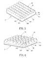
- FIG. 5is a perspective view of the brightness enhancement film having the reinforcing structure in accordance with a fourth embodiment of the present invention.
- FIG. 6is a perspective view of the brightness enhancement film having the reinforcing structure in accordance with a fifth embodiment of the present invention.
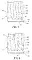
- FIG. 7is a partially enlarged perspective view of the brightness enhancement film having the reinforcing structure in accordance with a sixth embodiment of the present invention.
- FIG. 8is a partially enlarged perspective view of the brightness enhancement film having the reinforcing structure in accordance with a seventh embodiment of the present invention.
- FIG. 9is a partially enlarged perspective view of the brightness enhancement film having the reinforcing structure in accordance with an eighth embodiment of the present invention.
- a brightness enhancement film 1 having a reinforcing structure in accordance with a first embodiment of the present inventionincludes a light-refracting microstructure layer 10 , a substrate 11 and a reinforcing layer 13 .
- the substrate 11has a first surface 11 a and a second surface 11 b opposite thereto.
- the substrate 11is made from a transparent material to permit light to penetrate from the second surface 11 b to the first surface 11 a , and it further enhances brightness of light.
- the construction of the light-refracting microstructure layer 10 in accordance with the first embodiment of the present inventionshall be described in detail.
- the light-refracting microstructure layer 10is deployed on a light emission side of the substrate 11 with respect to a light source (not shown).
- the light-refracting microstructure layer 10consists of a plurality of prism units 12 .
- the prism units 12are arranged and juxtaposed on the first surface 11 a of the substrate 11 in order.
- Each of the prism units 12has a predetermined height raised from the first surface 11 a of the substrate 11 , and consists of a first flat inclined surface 12 a and a second flat inclined surface 12 b connected thereto.
- the first inclined surfaces 12 a and the second inclined surfaces 12 bserve to refract light penetrated through the substrate 11 in at least one dimension for enhancing brightness of light.
- the light-refracting microstructure layer 10 and the substrate 11are preferably made from all the same transparent material, such as an epoxy or UV (ultraviolet) curable adhesive having a specific degree of refractive index in nature.
- the light-refracting microstructure layer 10is integrally formed on the first surface 11 a of the substrate 11 .
- the light-refracting microstructure layer 10 and the substrate 11are separately made from different transparent materials and adhered to each other according to the design choice. Accordingly, the various materials and processes involved in the manufacture of the brightness enhancement film 1 can determine its performance and characteristics.
- the reinforcing layer 13covers the second surface 11 b of the substrate 11 to form a composite reinforced laminate by using one of coating, adhesive, physical vapor deposition or sputtering deposition.
- the reinforcing layer 13is deployed on a light incident side of the substrate 11 with respect to a light source (not shown).
- the reinforcing layer 13is made from a transparent material, such as an acrylic resin, having a lower degree of refractive index relative to that of the substrate 11 .
- the transparent material of the reinforcing layer 13has a hardness greater than that of the substrate 11 such that the reinforcing layer 13 can protect the second surface 11 b of the substrate 11 from abrasion.
- the transparent material of the reinforcing layer 13also has a rate of shrinkage substantially similar or approximately to that of the substrate 11 .
- the reinforcing layer 13is designed to possess a thickness ranging between 5 ⁇ m and 10 ⁇ m which may be achieved at a relatively reasonable cost in that the minimum of material is used in the intended manner.
- the quality of the reinforcing layer 13can be controlled by such a thickness.
- dimensions of the reinforcing layer 13bear adequate strength to withstand normal usage of the brightness enhancement film 1 .
- the manufacture of the brightness enhancement film 1 in accordance with the first embodiment of the present inventionshall be described in detail.
- the arrangement of the first inclined surfaces 12 a and the second inclined surfaces 12 b of the prism units 12can be varied according to the design need. Such practice may, however, cause spontaneous warpage of the substrate 11 .
- the reinforcing layer 13can perform a relatively high degree of hardness that may alleviate the possibility of occurring warpage of the brightness enhancement film 1 . Consequently, the brightness enhancement film 1 has a high degree of warpage resistance.
- the hardness of the reinforcing layer 13can protect the second surface 11 b of the substrate 11 against abrasion and scraping. Consequently, the brightness enhancement film 1 can carry out a high degree of abrasion resistance.
- the brightness enhancement film 2having a reinforcing structure in accordance with a second embodiment of the present invention is illustrated.
- the brightness enhancement film 2includes a light-refracting microstructure layer 20 , a substrate 21 and a reinforcing layer 23 which are stacked to constitute the brightness enhancement film 2 .
- the substrate 21has a first surface 21 a and a second surface 21 b opposite thereto.
- the light-refracting microstructure layer 20consists of a plurality of micro-hemispheres 22 which are raised on the first surface 21 a of the substrate 21 in order to form hexagonal units.
- the reinforcing layer 23covers the second surface 21 b of the substrate 21 to form a composite reinforced laminate.
- the micro-hemispheres 22 of the light-refracting microstructure layer 20are used to refract light and are arranged to form a plurality of hexagonal units in a hexagonal manner such that each of the micro-hemispheres 22 has six of the adjacent micro-hemispheres 22 .
- the micro-hemispheres 22serve to circularly refract light penetrated through the substrate 21 in two dimensions for enhancing brightness of light.
- the reinforcing layer 13can perform a relatively high degree of hardness so that the brightness enhancement film 1 has a high degree of warpage resistance and abrasion resistance.
- the brightness enhancement film 2having a reinforcing structure in accordance with a third embodiment of the present invention is illustrated.
- the brightness enhancement film 2includes a light-refracting microstructure layer 20 , a substrate 21 and a reinforcing layer 23 which are stacked to constitute the brightness enhancement film 2 .
- the substrate 21has a first surface 21 a and a second surface 21 b opposite thereto.
- the light-refracting microstructure layer 20consists of a plurality of micro cones 22 ′ which are raised on the first surface 21 a of the substrate 21 in order to form hexagonal units.
- the reinforcing layer 23covers the second surface 21 b of the substrate 21 to form a composite reinforced laminate.
- the micro cones 22 ′ of the light-refracting microstructure layer 20are used to refract light and are arranged to form a plurality of hexagonal units in a hexagonal manner such that each of the micro cones 22 ′ has six of the adjacent micro cones 22 ′.
- the micro cones 22 ′serve to circularly refract light penetrated through the substrate 21 in two dimensions for enhancing brightness of light.
- the micro cones 22 ′ of the third embodimentcan advantageously alleviate the deficiency of bright light spots generated from the micro-hemispheres 22 of the second embodiment.
- the reinforcing layer 23can perform a relatively high degree of hardness so that the brightness enhancement film 2 has a high degree of warpage resistance and abrasion resistance.
- the brightness enhancement film 3having a reinforcing structure in accordance with a fourth embodiment of the present invention is illustrated.
- the brightness enhancement film 3includes a light-refracting microstructure layer 30 , a substrate 31 and a reinforcing layer 33 which are stacked to constitute the brightness enhancement film 3 .
- the substrate 31has a first surface 31 a and a second surface 31 b opposite thereto.
- the light-refracting microstructure layer 30consists of a plurality of micro rippled ridges 32 which are raised and juxtaposed on the first surface 31 a of the substrate 31 in order.
- Each of the micro rippled ridges 32consists of a plurality of micro light-condensing units 320 substantially having a common height, and each of which has a pair of curved surfaces 321 , a pair of common trough lines 322 and a common ridgeline 323 .
- the curved surface 321 of the micro light-condensing units 320has an inclination from the common ridgeline 323 to the common trough line 322 .
- the common trough line 322is substantially constructed from a straight line while the common ridgeline 323 is substantially constructed from a curved line.
- the reinforcing layer 33covers the second surface 31 b of the substrate 31 to form a composite reinforced laminate.
- the micro light-condensing units 320serve to refract light penetrated through the substrate 31 in two dimensions for enhancing brightness of light.
- the reinforcing layer 33can perform a relatively high degree of hardness so that the brightness enhancement film 3 has a high degree of warpage resistance and abrasion resistance.
- the brightness enhancement film 3having a reinforcing structure in accordance with a fifth embodiment of the present invention is illustrated.
- the brightness enhancement film 3includes a light-refracting microstructure layer 30 , a substrate 31 and a reinforcing layer 33 which are stacked to constitute the brightness enhancement film 3 .
- the substrate 31has a first surface 31 a and a second surface 31 b opposite thereto.
- the light-refracting microstructure layer 30consists of a plurality of micro rippled ridges 32 which are raised and juxtaposed on the first surface 31 a of the substrate 31 in order.
- Each of the micro rippled ridges 32consists of a plurality of micro light-condensing units 320 ′ substantially having a common height, and each of which has a pair of curved surfaces 321 ′, a pair of trough bottom lines 322 ′ and a peak line 323 ′.
- the curved surface 321 ′ of the micro light-condensing units 320 ′has a uniform curvature from the peak line 323 ′ to the trough bottom line 322 ′.
- the trough bottom line 322 ′ of the fifth embodimentis substantially constructed from a curved line which permits a portion of the curved surface 321 ′ adjacent to the trough bottom line 322 ′ to have a uniform curvature.
- the reinforcing layer 33covers the second surface 31 b of the substrate 31 to form a composite reinforced laminate.
- the micro light-condensing units 320 ′serve to refract light penetrated through the substrate 31 in two dimensions for enhancing brightness of light.
- the reinforcing layer 33can perform a relatively high degree of hardness so that the brightness enhancement film 3 has a high degree of warpage resistance and abrasion resistance.
- the brightness enhancement film 4having a reinforcing structure in accordance with a sixth embodiment of the present invention is illustrated.
- the brightness enhancement film 4includes a light-refracting microstructure layer 40 , a substrate 41 and a reinforcing layer 43 which are stacked to constitute the brightness enhancement film 4 .
- the substrate 41has a first surface 41 a and a second surface 41 b opposite thereto.
- the light-refracting microstructure layer 40 of the sixth embodimentconsists of a plurality of curved prism units 42 which are raised on the first surface 41 a of the substrate 41 and parallel to each other.
- each of the curved prism units 42has a pair of meandering surfaces 42 a , 42 b , a pair of common trough lines 421 and a common ridge 422 .
- each of the curved prisms 42substantially has a common horizontal width and a common vertical height, and each of the meandering surfaces 42 a , 42 b of the curved prisms 42 substantially has the same changes in curvature. At least one of the meandering surfaces 42 a and 42 b forms a curved surface having changes in curvature.
- the meandering surfaces 42 a , 42 bserve to refract light penetrated through the substrate 41 in two dimensions for enhancing brightness of light and attenuating morie phenomenon. Additionally, the reinforcing layer 43 can perform a relatively high degree of hardness so that the brightness enhancement film 4 has a high degree of warpage resistance and abrasion resistance.
- the brightness enhancement film 4having a reinforcing structure in accordance with a seventh embodiment of the present invention is illustrated.
- the brightness enhancement film 4includes a light-refracting microstructure layer 40 , a substrate 41 and a reinforcing layer 43 which are stacked to constitute the brightness enhancement film 4 .
- the substrate 41has a first surface 41 a and a second surface 41 b opposite thereto.
- the light-refracting microstructure layer 40consists of a plurality of curved prism units 42 which are raised on the first surface 41 a of the substrate 41 and parallel to each other.
- the reinforcing layer 43covers the second surface 41 b of the substrate 41 to form a composite reinforced laminate.
- Each of the curved prism units 42has a pair of meandering surfaces 42 a , 42 b , a pair of common trough lines 421 and a common ridge 422 .
- each of the curved prisms 42 of the seventh embodimentsubstantially has a common vertical height but varies in horizontal widths such that each of the meandering surfaces 42 a , 42 b of the curved prisms 42 varies in curvature.
- At least one of the meandering surfaces 42 a and 42 bforms a curved surface having changes in curvature.
- the meandering surfaces 42 a , 42 bserve to refract light penetrated through the substrate 41 in two dimensions for enhancing brightness of light and attenuating morie phenomenon.
- the reinforcing layer 43can perform a relatively high degree of hardness so that the brightness enhancement film 4 has a high degree of warpage resistance and abrasion resistance.
- the brightness enhancement film 4having a reinforcing structure in accordance with an eighth embodiment of the present invention is illustrated.
- the brightness enhancement film 4includes a light-refracting microstructure layer 40 , a substrate 41 and a reinforcing layer 43 which are stacked to constitute the brightness enhancement film 4 .
- the substrate 41has a first surface 41 a and a second surface 41 b opposite thereto.
- the light-refracting microstructure layer 40consists of a plurality of curved prism units 42 which are raised on the first surface 41 a of the substrate 41 and parallel to each other.
- the reinforcing layer 43covers the second surface 41 b of the substrate 41 to form a composite reinforced laminate.
- Each of the curved prism units 42has a pair of meandering surfaces 42 a , 42 b , a pair of common trough lines 421 and a common ridge 422 .
- each of the curved prisms 42 of the eighth embodimentsubstantially has a common horizontal width but varies in vertical heights such that each of the meandering surfaces 42 a , 42 b of the curved prisms 42 varies in curvature.
- each of the first meandering surface 42 a and the second meandering surface 42 bconsists of a plurality of lateral ridges 423 arranged in staggered manner in a longitudinal direction to provide changes in curvature.
- the meandering surfaces 42 a , 42 bserve to refract light penetrated through the substrate 41 in two dimensions for enhancing brightness of light and attenuating morie phenomenon. Additionally, the reinforcing layer 43 can perform a relatively high degree of hardness so that the brightness enhancement film 4 has a high degree of warpage resistance and abrasion resistance.
- the top surface and the bottom surface disposed on the substrate 11are unmatched in structure which may cause a specific degree of warpage of the brightness enhancement film 1 in nature, as shown in FIG. 1 .
- the substrate 11 provided with the light-refracting microstructure layer 10 and the reinforcing layer 13 on the first surface 11 a and the second surface 11 bform the brightness enhancement film 1 .
- the reinforcing layer 13can perform a relatively high degree of hardness so that the brightness enhancement film 1 has a high degree of warpage resistance and abrasion resistance, as best shown in FIG. 2 .
Landscapes
- Physics & Mathematics (AREA)
- General Physics & Mathematics (AREA)
- Optics & Photonics (AREA)
- Laminated Bodies (AREA)
- Optical Elements Other Than Lenses (AREA)
- Planar Illumination Modules (AREA)
- Liquid Crystal (AREA)
- Optical Record Carriers And Manufacture Thereof (AREA)
- Surface Treatment Of Optical Elements (AREA)
Abstract
Description
Claims (28)
Applications Claiming Priority (2)
| Application Number | Priority Date | Filing Date | Title |
|---|---|---|---|
| TW94122042 | 2005-06-30 | ||
| TW094122042ATWI274896B (en) | 2005-06-30 | 2005-06-30 | Brightness enhancement film having reinforcing layer |
Publications (2)
| Publication Number | Publication Date |
|---|---|
| US20070002471A1 US20070002471A1 (en) | 2007-01-04 |
| US7269327B2true US7269327B2 (en) | 2007-09-11 |
Family
ID=37589185
Family Applications (1)
| Application Number | Title | Priority Date | Filing Date |
|---|---|---|---|
| US11/160,992Expired - Fee RelatedUS7269327B2 (en) | 2005-06-30 | 2005-07-19 | Brightness enhancement film having a reinforcing structure |
Country Status (3)
| Country | Link |
|---|---|
| US (1) | US7269327B2 (en) |
| JP (1) | JP3115145U (en) |
| TW (1) | TWI274896B (en) |
Cited By (41)
| Publication number | Priority date | Publication date | Assignee | Title |
|---|---|---|---|---|
| US20070291369A1 (en)* | 2006-06-19 | 2007-12-20 | Takashi Shimura | Optical element, lighting device, and liquid crystal display device |
| US20080049451A1 (en)* | 2005-12-06 | 2008-02-28 | Kong-Hua Wang | Luminance enhancement optical substrates with anti-chatter structures |
| US20100103351A1 (en)* | 2007-05-25 | 2010-04-29 | Cheil Indusstries | Prism sheet having wet-out property and lcd back light unit thereby |
| US7815326B2 (en) | 2002-06-06 | 2010-10-19 | Donnelly Corporation | Interior rearview mirror system |
| US7821697B2 (en) | 1994-05-05 | 2010-10-26 | Donnelly Corporation | Exterior reflective mirror element for a vehicular rearview mirror assembly |
| US7822543B2 (en) | 2000-03-02 | 2010-10-26 | Donnelly Corporation | Video display system for vehicle |
| US7826123B2 (en) | 2002-09-20 | 2010-11-02 | Donnelly Corporation | Vehicular interior electrochromic rearview mirror assembly |
| US7832882B2 (en) | 2002-06-06 | 2010-11-16 | Donnelly Corporation | Information mirror system |
| US7855755B2 (en) | 2005-11-01 | 2010-12-21 | Donnelly Corporation | Interior rearview mirror assembly with display |
| US7859737B2 (en) | 2002-09-20 | 2010-12-28 | Donnelly Corporation | Interior rearview mirror system for a vehicle |
| US7864399B2 (en) | 2002-09-20 | 2011-01-04 | Donnelly Corporation | Reflective mirror assembly |
| US7871169B2 (en) | 1994-05-05 | 2011-01-18 | Donnelly Corporation | Vehicular signal mirror |
| US7888629B2 (en) | 1998-01-07 | 2011-02-15 | Donnelly Corporation | Vehicular accessory mounting system with a forwardly-viewing camera |
| US7898398B2 (en) | 1997-08-25 | 2011-03-01 | Donnelly Corporation | Interior mirror system |
| US7898719B2 (en) | 2003-10-02 | 2011-03-01 | Donnelly Corporation | Rearview mirror assembly for vehicle |
| WO2011025963A1 (en) | 2009-08-28 | 2011-03-03 | 3M Innovative Properties Company | Optical device with antistatic coating |
| US7906756B2 (en) | 2002-05-03 | 2011-03-15 | Donnelly Corporation | Vehicle rearview mirror system |
| US7916009B2 (en) | 1998-01-07 | 2011-03-29 | Donnelly Corporation | Accessory mounting system suitable for use in a vehicle |
| US7914188B2 (en) | 1997-08-25 | 2011-03-29 | Donnelly Corporation | Interior rearview mirror system for a vehicle |
| WO2011038279A1 (en) | 2009-09-24 | 2011-03-31 | 3M Innovative Properties Company | Web conveyance method and apparatus using same |
| US7926960B2 (en) | 1999-11-24 | 2011-04-19 | Donnelly Corporation | Interior rearview mirror system for vehicle |
| WO2011053709A2 (en) | 2009-10-30 | 2011-05-05 | 3M Innovative Properties Company | Optical device with antistatic property |
| US8019505B2 (en) | 2003-10-14 | 2011-09-13 | Donnelly Corporation | Vehicle information display |
| US8044776B2 (en) | 2000-03-02 | 2011-10-25 | Donnelly Corporation | Rear vision system for vehicle |
| US8072318B2 (en) | 2001-01-23 | 2011-12-06 | Donnelly Corporation | Video mirror system for vehicle |
| US8083386B2 (en) | 2001-01-23 | 2011-12-27 | Donnelly Corporation | Interior rearview mirror assembly with display device |
| US8154418B2 (en) | 2008-03-31 | 2012-04-10 | Magna Mirrors Of America, Inc. | Interior rearview mirror system |
| US8194133B2 (en) | 2000-03-02 | 2012-06-05 | Donnelly Corporation | Vehicular video mirror system |
| US8288711B2 (en) | 1998-01-07 | 2012-10-16 | Donnelly Corporation | Interior rearview mirror system with forwardly-viewing camera and a control |
| US8294975B2 (en) | 1997-08-25 | 2012-10-23 | Donnelly Corporation | Automotive rearview mirror assembly |
| US8462204B2 (en) | 1995-05-22 | 2013-06-11 | Donnelly Corporation | Vehicular vision system |
| WO2013102022A1 (en) | 2011-12-30 | 2013-07-04 | 3M Innovative Properties Company | Vacuum effector and method of use |
| US8503062B2 (en) | 2005-05-16 | 2013-08-06 | Donnelly Corporation | Rearview mirror element assembly for vehicle |
| US8525703B2 (en) | 1998-04-08 | 2013-09-03 | Donnelly Corporation | Interior rearview mirror system |
| US8742047B2 (en) | 2009-08-28 | 2014-06-03 | 3M Innovative Properties Company | Polymerizable ionic liquid comprising multifunctional cation and antistatic coatings |
| US8816029B2 (en) | 2009-08-28 | 2014-08-26 | 3M Innovative Properties Company | Compositions and articles comprising polymerizable ionic liquid mixture, and methods of curing |
| US8853338B2 (en) | 2009-12-22 | 2014-10-07 | 3M Innovative Properties Company | Curable dental compositions and articles comprising polymerizable ionic liquids |
| US20150043220A1 (en)* | 2012-02-16 | 2015-02-12 | Koninklijke Philips N.V. | Using micro optical elements for depth perception in luminescent figurative structures illuminated by point sources |
| US9019091B2 (en) | 1999-11-24 | 2015-04-28 | Donnelly Corporation | Interior rearview mirror system |
| US9487144B2 (en) | 2008-10-16 | 2016-11-08 | Magna Mirrors Of America, Inc. | Interior mirror assembly with display |
| US9915762B2 (en) | 2012-08-21 | 2018-03-13 | 3M Innovative Properties Company | Articles with binder-deficient slip coating and method for making same |
Families Citing this family (8)
| Publication number | Priority date | Publication date | Assignee | Title |
|---|---|---|---|---|
| JP2595466B2 (en) | 1994-04-27 | 1997-04-02 | 渋谷 彰一 | Manhole cover frame removal equipment and removal method |
| TWI274896B (en)* | 2005-06-30 | 2007-03-01 | Efun Technology Co Ltd | Brightness enhancement film having reinforcing layer |
| TWI391711B (en)* | 2005-09-13 | 2013-04-01 | Efun Technology Co Ltd | Brightness enhancement film having a light-guiding layer |
| US20080225202A1 (en)* | 2007-03-15 | 2008-09-18 | Hanbitt Joo | Optical sheet and liquid crystal display device having the same |
| CN101393283B (en)* | 2007-09-21 | 2010-12-01 | 鸿富锦精密工业(深圳)有限公司 | Prism sheet and liquid crystal display using the prism sheet |
| TW201126208A (en) | 2010-01-21 | 2011-08-01 | Core Flex Optical Suzhou Co Ltd | Brightness enhancement sheet |
| CN102236122B (en) | 2010-04-30 | 2012-12-19 | 中强光电股份有限公司 | Optical film |
| CN103809230A (en)* | 2012-11-14 | 2014-05-21 | 友辉光电股份有限公司 | Brightness enhancement film, backlight module and liquid crystal display device |
Citations (16)
| Publication number | Priority date | Publication date | Assignee | Title |
|---|---|---|---|---|
| US5245454A (en)* | 1991-12-31 | 1993-09-14 | At&T Bell Laboratories | Lcd display with microtextured back reflector and method for making same |
| US5300263A (en) | 1992-10-28 | 1994-04-05 | Minnesota Mining And Manufacturing Company | Method of making a microlens array and mold |
| US5626800A (en) | 1995-02-03 | 1997-05-06 | Minnesota Mining And Manufacturing Company | Prevention of groove tip deformation in brightness enhancement film |
| US5919551A (en) | 1996-04-12 | 1999-07-06 | 3M Innovative Properties Company | Variable pitch structured optical film |
| US6277471B1 (en)* | 1999-06-18 | 2001-08-21 | Shih Chieh Tang | Brightness enhancement film |
| US6280063B1 (en) | 1997-05-09 | 2001-08-28 | 3M Innovative Properties Company | Brightness enhancement article |
| US6581286B2 (en)* | 2000-04-05 | 2003-06-24 | 3M Innovative Properties Company | Method of making tool to produce optical film |
| US6759113B1 (en)* | 2003-03-24 | 2004-07-06 | Shih-Chieh Tang | Uniform curved surface structure of a brightness unit for a brightness enhancement film |
| US20050007513A1 (en)* | 2003-03-05 | 2005-01-13 | Lee Jeong-Hwan | Optical sheet and LCD apparatus using the same |
| US6845212B2 (en)* | 1999-10-08 | 2005-01-18 | 3M Innovative Properties Company | Optical element having programmed optical structures |
| US6862141B2 (en)* | 2002-05-20 | 2005-03-01 | General Electric Company | Optical substrate and method of making |
| US6951400B2 (en)* | 2002-12-04 | 2005-10-04 | General Electric Company | High index coated light management films |
| US20050237641A1 (en)* | 2004-04-22 | 2005-10-27 | Shih-Chieh Tang | Brightness enhancement film having curved prism units |
| US6981792B2 (en)* | 2002-12-06 | 2006-01-03 | Alps Electric Co., Ltd. | Backlight device and liquid crystal display device |
| US7090389B2 (en)* | 1999-02-23 | 2006-08-15 | Solid State Opto Limited | Method of selecting a light redirecting film |
| US20070002471A1 (en)* | 2005-06-30 | 2007-01-04 | Efun Technology Co., Ltd. | Brightness enhancement film having a reinforcing structure |
- 2005
- 2005-06-30TWTW094122042Apatent/TWI274896B/ennot_activeIP Right Cessation
- 2005-07-19USUS11/160,992patent/US7269327B2/ennot_activeExpired - Fee Related
- 2005-07-27JPJP2005005986Upatent/JP3115145U/ennot_activeExpired - Lifetime
Patent Citations (16)
| Publication number | Priority date | Publication date | Assignee | Title |
|---|---|---|---|---|
| US5245454A (en)* | 1991-12-31 | 1993-09-14 | At&T Bell Laboratories | Lcd display with microtextured back reflector and method for making same |
| US5300263A (en) | 1992-10-28 | 1994-04-05 | Minnesota Mining And Manufacturing Company | Method of making a microlens array and mold |
| US5626800A (en) | 1995-02-03 | 1997-05-06 | Minnesota Mining And Manufacturing Company | Prevention of groove tip deformation in brightness enhancement film |
| US5919551A (en) | 1996-04-12 | 1999-07-06 | 3M Innovative Properties Company | Variable pitch structured optical film |
| US6280063B1 (en) | 1997-05-09 | 2001-08-28 | 3M Innovative Properties Company | Brightness enhancement article |
| US7090389B2 (en)* | 1999-02-23 | 2006-08-15 | Solid State Opto Limited | Method of selecting a light redirecting film |
| US6277471B1 (en)* | 1999-06-18 | 2001-08-21 | Shih Chieh Tang | Brightness enhancement film |
| US6845212B2 (en)* | 1999-10-08 | 2005-01-18 | 3M Innovative Properties Company | Optical element having programmed optical structures |
| US6581286B2 (en)* | 2000-04-05 | 2003-06-24 | 3M Innovative Properties Company | Method of making tool to produce optical film |
| US6862141B2 (en)* | 2002-05-20 | 2005-03-01 | General Electric Company | Optical substrate and method of making |
| US6951400B2 (en)* | 2002-12-04 | 2005-10-04 | General Electric Company | High index coated light management films |
| US6981792B2 (en)* | 2002-12-06 | 2006-01-03 | Alps Electric Co., Ltd. | Backlight device and liquid crystal display device |
| US20050007513A1 (en)* | 2003-03-05 | 2005-01-13 | Lee Jeong-Hwan | Optical sheet and LCD apparatus using the same |
| US6759113B1 (en)* | 2003-03-24 | 2004-07-06 | Shih-Chieh Tang | Uniform curved surface structure of a brightness unit for a brightness enhancement film |
| US20050237641A1 (en)* | 2004-04-22 | 2005-10-27 | Shih-Chieh Tang | Brightness enhancement film having curved prism units |
| US20070002471A1 (en)* | 2005-06-30 | 2007-01-04 | Efun Technology Co., Ltd. | Brightness enhancement film having a reinforcing structure |
Cited By (149)
| Publication number | Priority date | Publication date | Assignee | Title |
|---|---|---|---|---|
| US8164817B2 (en) | 1994-05-05 | 2012-04-24 | Donnelly Corporation | Method of forming a mirrored bent cut glass shape for vehicular exterior rearview mirror assembly |
| US8511841B2 (en) | 1994-05-05 | 2013-08-20 | Donnelly Corporation | Vehicular blind spot indicator mirror |
| US7871169B2 (en) | 1994-05-05 | 2011-01-18 | Donnelly Corporation | Vehicular signal mirror |
| US7821697B2 (en) | 1994-05-05 | 2010-10-26 | Donnelly Corporation | Exterior reflective mirror element for a vehicular rearview mirror assembly |
| US8559093B2 (en) | 1995-04-27 | 2013-10-15 | Donnelly Corporation | Electrochromic mirror reflective element for vehicular rearview mirror assembly |
| US8462204B2 (en) | 1995-05-22 | 2013-06-11 | Donnelly Corporation | Vehicular vision system |
| US8842176B2 (en) | 1996-05-22 | 2014-09-23 | Donnelly Corporation | Automatic vehicle exterior light control |
| US8100568B2 (en) | 1997-08-25 | 2012-01-24 | Donnelly Corporation | Interior rearview mirror system for a vehicle |
| US7898398B2 (en) | 1997-08-25 | 2011-03-01 | Donnelly Corporation | Interior mirror system |
| US8309907B2 (en) | 1997-08-25 | 2012-11-13 | Donnelly Corporation | Accessory system suitable for use in a vehicle and accommodating a rain sensor |
| US8779910B2 (en) | 1997-08-25 | 2014-07-15 | Donnelly Corporation | Interior rearview mirror system |
| US8610992B2 (en) | 1997-08-25 | 2013-12-17 | Donnelly Corporation | Variable transmission window |
| US8267559B2 (en) | 1997-08-25 | 2012-09-18 | Donnelly Corporation | Interior rearview mirror assembly for a vehicle |
| US7914188B2 (en) | 1997-08-25 | 2011-03-29 | Donnelly Corporation | Interior rearview mirror system for a vehicle |
| US8063753B2 (en) | 1997-08-25 | 2011-11-22 | Donnelly Corporation | Interior rearview mirror system |
| US8294975B2 (en) | 1997-08-25 | 2012-10-23 | Donnelly Corporation | Automotive rearview mirror assembly |
| US7994471B2 (en) | 1998-01-07 | 2011-08-09 | Donnelly Corporation | Interior rearview mirror system with forwardly-viewing camera |
| US8094002B2 (en) | 1998-01-07 | 2012-01-10 | Donnelly Corporation | Interior rearview mirror system |
| US7916009B2 (en) | 1998-01-07 | 2011-03-29 | Donnelly Corporation | Accessory mounting system suitable for use in a vehicle |
| US7888629B2 (en) | 1998-01-07 | 2011-02-15 | Donnelly Corporation | Vehicular accessory mounting system with a forwardly-viewing camera |
| US8134117B2 (en) | 1998-01-07 | 2012-03-13 | Donnelly Corporation | Vehicular having a camera, a rain sensor and a single-ball interior electrochromic mirror assembly attached at an attachment element |
| US8325028B2 (en) | 1998-01-07 | 2012-12-04 | Donnelly Corporation | Interior rearview mirror system |
| US8288711B2 (en) | 1998-01-07 | 2012-10-16 | Donnelly Corporation | Interior rearview mirror system with forwardly-viewing camera and a control |
| US8884788B2 (en) | 1998-04-08 | 2014-11-11 | Donnelly Corporation | Automotive communication system |
| US8525703B2 (en) | 1998-04-08 | 2013-09-03 | Donnelly Corporation | Interior rearview mirror system |
| US9221399B2 (en) | 1998-04-08 | 2015-12-29 | Magna Mirrors Of America, Inc. | Automotive communication system |
| US9481306B2 (en) | 1998-04-08 | 2016-11-01 | Donnelly Corporation | Automotive communication system |
| US7926960B2 (en) | 1999-11-24 | 2011-04-19 | Donnelly Corporation | Interior rearview mirror system for vehicle |
| US9019091B2 (en) | 1999-11-24 | 2015-04-28 | Donnelly Corporation | Interior rearview mirror system |
| US9278654B2 (en) | 1999-11-24 | 2016-03-08 | Donnelly Corporation | Interior rearview mirror system for vehicle |
| US8162493B2 (en) | 1999-11-24 | 2012-04-24 | Donnelly Corporation | Interior rearview mirror assembly for vehicle |
| US9376061B2 (en) | 1999-11-24 | 2016-06-28 | Donnelly Corporation | Accessory system of a vehicle |
| US10144355B2 (en) | 1999-11-24 | 2018-12-04 | Donnelly Corporation | Interior rearview mirror system for vehicle |
| US8121787B2 (en) | 2000-03-02 | 2012-02-21 | Donnelly Corporation | Vehicular video mirror system |
| US9809171B2 (en) | 2000-03-02 | 2017-11-07 | Magna Electronics Inc. | Vision system for vehicle |
| US9014966B2 (en) | 2000-03-02 | 2015-04-21 | Magna Electronics Inc. | Driver assist system for vehicle |
| US9019090B2 (en) | 2000-03-02 | 2015-04-28 | Magna Electronics Inc. | Vision system for vehicle |
| US7822543B2 (en) | 2000-03-02 | 2010-10-26 | Donnelly Corporation | Video display system for vehicle |
| US8676491B2 (en) | 2000-03-02 | 2014-03-18 | Magna Electronics Inc. | Driver assist system for vehicle |
| US9315151B2 (en) | 2000-03-02 | 2016-04-19 | Magna Electronics Inc. | Driver assist system for vehicle |
| US8543330B2 (en) | 2000-03-02 | 2013-09-24 | Donnelly Corporation | Driver assist system for vehicle |
| US9783114B2 (en) | 2000-03-02 | 2017-10-10 | Donnelly Corporation | Vehicular video mirror system |
| US8044776B2 (en) | 2000-03-02 | 2011-10-25 | Donnelly Corporation | Rear vision system for vehicle |
| US9809168B2 (en) | 2000-03-02 | 2017-11-07 | Magna Electronics Inc. | Driver assist system for vehicle |
| US8179236B2 (en) | 2000-03-02 | 2012-05-15 | Donnelly Corporation | Video mirror system suitable for use in a vehicle |
| US10239457B2 (en) | 2000-03-02 | 2019-03-26 | Magna Electronics Inc. | Vehicular vision system |
| US8427288B2 (en) | 2000-03-02 | 2013-04-23 | Donnelly Corporation | Rear vision system for a vehicle |
| US8194133B2 (en) | 2000-03-02 | 2012-06-05 | Donnelly Corporation | Vehicular video mirror system |
| US8908039B2 (en) | 2000-03-02 | 2014-12-09 | Donnelly Corporation | Vehicular video mirror system |
| US10179545B2 (en) | 2000-03-02 | 2019-01-15 | Magna Electronics Inc. | Park-aid system for vehicle |
| US8271187B2 (en) | 2000-03-02 | 2012-09-18 | Donnelly Corporation | Vehicular video mirror system |
| US8095310B2 (en) | 2000-03-02 | 2012-01-10 | Donnelly Corporation | Video mirror system for a vehicle |
| US10053013B2 (en) | 2000-03-02 | 2018-08-21 | Magna Electronics Inc. | Vision system for vehicle |
| US10131280B2 (en) | 2000-03-02 | 2018-11-20 | Donnelly Corporation | Vehicular video mirror system |
| US8000894B2 (en) | 2000-03-02 | 2011-08-16 | Donnelly Corporation | Vehicular wireless communication system |
| US10272839B2 (en) | 2001-01-23 | 2019-04-30 | Magna Electronics Inc. | Rear seat occupant monitoring system for vehicle |
| US8083386B2 (en) | 2001-01-23 | 2011-12-27 | Donnelly Corporation | Interior rearview mirror assembly with display device |
| US8654433B2 (en) | 2001-01-23 | 2014-02-18 | Magna Mirrors Of America, Inc. | Rearview mirror assembly for vehicle |
| US8653959B2 (en) | 2001-01-23 | 2014-02-18 | Donnelly Corporation | Video mirror system for a vehicle |
| US8072318B2 (en) | 2001-01-23 | 2011-12-06 | Donnelly Corporation | Video mirror system for vehicle |
| US9352623B2 (en) | 2001-01-23 | 2016-05-31 | Magna Electronics Inc. | Trailer hitching aid system for vehicle |
| US9694749B2 (en) | 2001-01-23 | 2017-07-04 | Magna Electronics Inc. | Trailer hitching aid system for vehicle |
| US8304711B2 (en) | 2002-05-03 | 2012-11-06 | Donnelly Corporation | Vehicle rearview mirror system |
| US8106347B2 (en) | 2002-05-03 | 2012-01-31 | Donnelly Corporation | Vehicle rearview mirror system |
| US7906756B2 (en) | 2002-05-03 | 2011-03-15 | Donnelly Corporation | Vehicle rearview mirror system |
| US8177376B2 (en) | 2002-06-06 | 2012-05-15 | Donnelly Corporation | Vehicular interior rearview mirror system |
| US8608327B2 (en) | 2002-06-06 | 2013-12-17 | Donnelly Corporation | Automatic compass system for vehicle |
| US8465163B2 (en) | 2002-06-06 | 2013-06-18 | Donnelly Corporation | Interior rearview mirror system |
| US8047667B2 (en) | 2002-06-06 | 2011-11-01 | Donnelly Corporation | Vehicular interior rearview mirror system |
| US8282226B2 (en) | 2002-06-06 | 2012-10-09 | Donnelly Corporation | Interior rearview mirror system |
| US7832882B2 (en) | 2002-06-06 | 2010-11-16 | Donnelly Corporation | Information mirror system |
| US7918570B2 (en) | 2002-06-06 | 2011-04-05 | Donnelly Corporation | Vehicular interior rearview information mirror system |
| US7815326B2 (en) | 2002-06-06 | 2010-10-19 | Donnelly Corporation | Interior rearview mirror system |
| US8465162B2 (en) | 2002-06-06 | 2013-06-18 | Donnelly Corporation | Vehicular interior rearview mirror system |
| US7864399B2 (en) | 2002-09-20 | 2011-01-04 | Donnelly Corporation | Reflective mirror assembly |
| US8727547B2 (en) | 2002-09-20 | 2014-05-20 | Donnelly Corporation | Variable reflectance mirror reflective element for exterior mirror assembly |
| US8277059B2 (en) | 2002-09-20 | 2012-10-02 | Donnelly Corporation | Vehicular electrochromic interior rearview mirror assembly |
| US10363875B2 (en) | 2002-09-20 | 2019-07-30 | Donnelly Corportion | Vehicular exterior electrically variable reflectance mirror reflective element assembly |
| US8228588B2 (en) | 2002-09-20 | 2012-07-24 | Donnelly Corporation | Interior rearview mirror information display system for a vehicle |
| US9878670B2 (en) | 2002-09-20 | 2018-01-30 | Donnelly Corporation | Variable reflectance mirror reflective element for exterior mirror assembly |
| US8335032B2 (en) | 2002-09-20 | 2012-12-18 | Donnelly Corporation | Reflective mirror assembly |
| US10538202B2 (en) | 2002-09-20 | 2020-01-21 | Donnelly Corporation | Method of manufacturing variable reflectance mirror reflective element for exterior mirror assembly |
| US8400704B2 (en) | 2002-09-20 | 2013-03-19 | Donnelly Corporation | Interior rearview mirror system for a vehicle |
| US9341914B2 (en) | 2002-09-20 | 2016-05-17 | Donnelly Corporation | Variable reflectance mirror reflective element for exterior mirror assembly |
| US10029616B2 (en) | 2002-09-20 | 2018-07-24 | Donnelly Corporation | Rearview mirror assembly for vehicle |
| US7859737B2 (en) | 2002-09-20 | 2010-12-28 | Donnelly Corporation | Interior rearview mirror system for a vehicle |
| US9090211B2 (en) | 2002-09-20 | 2015-07-28 | Donnelly Corporation | Variable reflectance mirror reflective element for exterior mirror assembly |
| US8797627B2 (en) | 2002-09-20 | 2014-08-05 | Donnelly Corporation | Exterior rearview mirror assembly |
| US9073491B2 (en) | 2002-09-20 | 2015-07-07 | Donnelly Corporation | Exterior rearview mirror assembly |
| US7826123B2 (en) | 2002-09-20 | 2010-11-02 | Donnelly Corporation | Vehicular interior electrochromic rearview mirror assembly |
| US8506096B2 (en) | 2002-09-20 | 2013-08-13 | Donnelly Corporation | Variable reflectance mirror reflective element for exterior mirror assembly |
| US10661716B2 (en) | 2002-09-20 | 2020-05-26 | Donnelly Corporation | Vehicular exterior electrically variable reflectance mirror reflective element assembly |
| US9545883B2 (en) | 2002-09-20 | 2017-01-17 | Donnelly Corporation | Exterior rearview mirror assembly |
| US8379289B2 (en) | 2003-10-02 | 2013-02-19 | Donnelly Corporation | Rearview mirror assembly for vehicle |
| US8179586B2 (en) | 2003-10-02 | 2012-05-15 | Donnelly Corporation | Rearview mirror assembly for vehicle |
| US7898719B2 (en) | 2003-10-02 | 2011-03-01 | Donnelly Corporation | Rearview mirror assembly for vehicle |
| US8705161B2 (en) | 2003-10-02 | 2014-04-22 | Donnelly Corporation | Method of manufacturing a reflective element for a vehicular rearview mirror assembly |
| US8577549B2 (en) | 2003-10-14 | 2013-11-05 | Donnelly Corporation | Information display system for a vehicle |
| US8355839B2 (en) | 2003-10-14 | 2013-01-15 | Donnelly Corporation | Vehicle vision system with night vision function |
| US8019505B2 (en) | 2003-10-14 | 2011-09-13 | Donnelly Corporation | Vehicle information display |
| US8170748B1 (en) | 2003-10-14 | 2012-05-01 | Donnelly Corporation | Vehicle information display system |
| US8095260B1 (en) | 2003-10-14 | 2012-01-10 | Donnelly Corporation | Vehicle information display |
| US8282253B2 (en) | 2004-11-22 | 2012-10-09 | Donnelly Corporation | Mirror reflective element sub-assembly for exterior rearview mirror of a vehicle |
| US8503062B2 (en) | 2005-05-16 | 2013-08-06 | Donnelly Corporation | Rearview mirror element assembly for vehicle |
| US10308186B2 (en) | 2005-09-14 | 2019-06-04 | Magna Mirrors Of America, Inc. | Vehicular exterior rearview mirror assembly with blind spot indicator |
| US10150417B2 (en) | 2005-09-14 | 2018-12-11 | Magna Mirrors Of America, Inc. | Mirror reflective element sub-assembly for exterior rearview mirror of a vehicle |
| US9045091B2 (en) | 2005-09-14 | 2015-06-02 | Donnelly Corporation | Mirror reflective element sub-assembly for exterior rearview mirror of a vehicle |
| US11285879B2 (en) | 2005-09-14 | 2022-03-29 | Magna Mirrors Of America, Inc. | Vehicular exterior rearview mirror assembly with blind spot indicator element |
| US9758102B1 (en) | 2005-09-14 | 2017-09-12 | Magna Mirrors Of America, Inc. | Mirror reflective element sub-assembly for exterior rearview mirror of a vehicle |
| US8833987B2 (en) | 2005-09-14 | 2014-09-16 | Donnelly Corporation | Mirror reflective element sub-assembly for exterior rearview mirror of a vehicle |
| US9694753B2 (en) | 2005-09-14 | 2017-07-04 | Magna Mirrors Of America, Inc. | Mirror reflective element sub-assembly for exterior rearview mirror of a vehicle |
| US10829053B2 (en) | 2005-09-14 | 2020-11-10 | Magna Mirrors Of America, Inc. | Vehicular exterior rearview mirror assembly with blind spot indicator |
| US11072288B2 (en) | 2005-09-14 | 2021-07-27 | Magna Mirrors Of America, Inc. | Vehicular exterior rearview mirror assembly with blind spot indicator element |
| US11124121B2 (en) | 2005-11-01 | 2021-09-21 | Magna Electronics Inc. | Vehicular vision system |
| US7855755B2 (en) | 2005-11-01 | 2010-12-21 | Donnelly Corporation | Interior rearview mirror assembly with display |
| US11970113B2 (en) | 2005-11-01 | 2024-04-30 | Magna Electronics Inc. | Vehicular vision system |
| US7712944B2 (en)* | 2005-12-06 | 2010-05-11 | Ubright Optronics Corporation | Luminance enhancement optical substrates with anti-chatter structures |
| US20080049451A1 (en)* | 2005-12-06 | 2008-02-28 | Kong-Hua Wang | Luminance enhancement optical substrates with anti-chatter structures |
| US20070291369A1 (en)* | 2006-06-19 | 2007-12-20 | Takashi Shimura | Optical element, lighting device, and liquid crystal display device |
| US20100103351A1 (en)* | 2007-05-25 | 2010-04-29 | Cheil Indusstries | Prism sheet having wet-out property and lcd back light unit thereby |
| US8384847B2 (en)* | 2007-05-25 | 2013-02-26 | Cheil Industries, Inc. | Prism sheet having wet-out property and LCD back light unit thereby |
| US8154418B2 (en) | 2008-03-31 | 2012-04-10 | Magna Mirrors Of America, Inc. | Interior rearview mirror system |
| US10175477B2 (en) | 2008-03-31 | 2019-01-08 | Magna Mirrors Of America, Inc. | Display system for vehicle |
| US8508383B2 (en) | 2008-03-31 | 2013-08-13 | Magna Mirrors of America, Inc | Interior rearview mirror system |
| US11577652B2 (en) | 2008-10-16 | 2023-02-14 | Magna Mirrors Of America, Inc. | Vehicular video camera display system |
| US10583782B2 (en) | 2008-10-16 | 2020-03-10 | Magna Mirrors Of America, Inc. | Interior mirror assembly with display |
| US11021107B2 (en) | 2008-10-16 | 2021-06-01 | Magna Mirrors Of America, Inc. | Vehicular interior rearview mirror system with display |
| US12054098B2 (en) | 2008-10-16 | 2024-08-06 | Magna Mirrors Of America, Inc. | Vehicular video camera display system |
| US11807164B2 (en) | 2008-10-16 | 2023-11-07 | Magna Mirrors Of America, Inc. | Vehicular video camera display system |
| US12391183B2 (en) | 2008-10-16 | 2025-08-19 | Magna Mirrors Of America, Inc. | Vehicular video camera display system |
| US9487144B2 (en) | 2008-10-16 | 2016-11-08 | Magna Mirrors Of America, Inc. | Interior mirror assembly with display |
| US8816029B2 (en) | 2009-08-28 | 2014-08-26 | 3M Innovative Properties Company | Compositions and articles comprising polymerizable ionic liquid mixture, and methods of curing |
| US11807795B2 (en) | 2009-08-28 | 2023-11-07 | 3M Innovative Properties Company | Optical device with antistatic coating |
| WO2011025963A1 (en) | 2009-08-28 | 2011-03-03 | 3M Innovative Properties Company | Optical device with antistatic coating |
| US9458327B2 (en) | 2009-08-28 | 2016-10-04 | 3M Innovative Properties Company | Polymerizable ionic liquid comprising multifunctional cation and antistatic coatings |
| US8742047B2 (en) | 2009-08-28 | 2014-06-03 | 3M Innovative Properties Company | Polymerizable ionic liquid comprising multifunctional cation and antistatic coatings |
| US9127101B2 (en) | 2009-08-28 | 2015-09-08 | 3M Innovative Properties Company | Compositions and articles comprising polymerizable ionic liquid mixture, and methods of curing |
| US10486932B2 (en) | 2009-09-24 | 2019-11-26 | 3M Innovative Properties Company | Web conveyance apparatus |
| US9845216B2 (en) | 2009-09-24 | 2017-12-19 | 3M Innovative Properties Company | Web conveyance method and apparatus using same |
| WO2011038279A1 (en) | 2009-09-24 | 2011-03-31 | 3M Innovative Properties Company | Web conveyance method and apparatus using same |
| WO2011038284A1 (en) | 2009-09-24 | 2011-03-31 | 3M Innovative Properties Company | Method for making engagement cover for rollers for web conveyance apparatus |
| US8784940B2 (en) | 2009-09-24 | 2014-07-22 | 3M Innovative Properties Company | Method for making engagement cover for rollers for web conveyance apparatus |
| US11111392B2 (en) | 2009-10-30 | 2021-09-07 | 3M Innovative Properties Company | Optical device with antistatic property |
| WO2011053709A2 (en) | 2009-10-30 | 2011-05-05 | 3M Innovative Properties Company | Optical device with antistatic property |
| US9168206B2 (en) | 2009-12-22 | 2015-10-27 | 3M Innovative Properties Company | Curable dental compositions and articles comprising polymerizable ionic liquids |
| US8853338B2 (en) | 2009-12-22 | 2014-10-07 | 3M Innovative Properties Company | Curable dental compositions and articles comprising polymerizable ionic liquids |
| WO2013102022A1 (en) | 2011-12-30 | 2013-07-04 | 3M Innovative Properties Company | Vacuum effector and method of use |
| US20150043220A1 (en)* | 2012-02-16 | 2015-02-12 | Koninklijke Philips N.V. | Using micro optical elements for depth perception in luminescent figurative structures illuminated by point sources |
| US9915762B2 (en) | 2012-08-21 | 2018-03-13 | 3M Innovative Properties Company | Articles with binder-deficient slip coating and method for making same |
Also Published As
| Publication number | Publication date |
|---|---|
| TW200700768A (en) | 2007-01-01 |
| TWI274896B (en) | 2007-03-01 |
| US20070002471A1 (en) | 2007-01-04 |
| JP3115145U (en) | 2005-11-04 |
Similar Documents
| Publication | Publication Date | Title |
|---|---|---|
| US7269327B2 (en) | Brightness enhancement film having a reinforcing structure | |
| US7269328B2 (en) | Brightness enhancement film having a light-guiding structure | |
| US7448776B2 (en) | Brightness enhancement film having curved prism units | |
| US20070115569A1 (en) | Brightness enhancement film having curved prism units and microstructure layer | |
| US8184235B2 (en) | Optical prism sheet, backlight unit, and liquid crystal display | |
| US8852470B2 (en) | Diffuser-integrated prism sheet for backlight units and method of manufacturing the same | |
| EP1445629A1 (en) | A light guide panel with slant light guiding parts | |
| US20070195224A1 (en) | Optical sheet and backlight module using the same | |
| US20070121227A1 (en) | Brightness enhancement film having curved prism units and light scattering particles | |
| KR20100103555A (en) | Backlight reflectors having a prismatic structure | |
| US8915604B2 (en) | Prism sheet, backlight unit including the same, and optical display apparatus including the same | |
| US7637645B2 (en) | Prism sheet and backlight module using the same | |
| KR20090096374A (en) | A single multi-layer optical sheet and a backlight assembly comprising the same for liquid crystal display | |
| US10310162B2 (en) | Optical component and display device having the same | |
| US7845811B2 (en) | Prism sheet and liquid crystal display device using the same | |
| US20090262528A1 (en) | Optical plate and backlight module using same | |
| US8177377B2 (en) | Optical plate and backlight module using the same | |
| TWI453507B (en) | Light source module | |
| US20090244715A1 (en) | Prism sheet | |
| US20090116219A1 (en) | Prism sheet and backlight module using the same | |
| KR20100033664A (en) | Optical sheet | |
| US20080062525A1 (en) | Diffusion plate having surface microstructure | |
| US20090109673A1 (en) | Prism sheet and backlight module using the same | |
| KR200398529Y1 (en) | Brightness enhancement film having a reinforcing structure | |
| US20100002462A1 (en) | Optical plate and backlight module using the same |
Legal Events
| Date | Code | Title | Description |
|---|---|---|---|
| AS | Assignment | Owner name:EFUN TECHNOLOGY CO., LTD., TAIWAN Free format text:ASSIGNMENT OF ASSIGNORS INTEREST;ASSIGNOR:TANG, SHIH-CHIEH;REEL/FRAME:016279/0597 Effective date:20050719 | |
| STCF | Information on status: patent grant | Free format text:PATENTED CASE | |
| FEPP | Fee payment procedure | Free format text:PAT HOLDER NO LONGER CLAIMS SMALL ENTITY STATUS, ENTITY STATUS SET TO UNDISCOUNTED (ORIGINAL EVENT CODE: STOL); ENTITY STATUS OF PATENT OWNER: SMALL ENTITY | |
| FPAY | Fee payment | Year of fee payment:4 | |
| SULP | Surcharge for late payment | ||
| REMI | Maintenance fee reminder mailed | ||
| FEPP | Fee payment procedure | Free format text:PAT HOLDER CLAIMS SMALL ENTITY STATUS, ENTITY STATUS SET TO SMALL (ORIGINAL EVENT CODE: LTOS); ENTITY STATUS OF PATENT OWNER: SMALL ENTITY | |
| FPAY | Fee payment | Year of fee payment:8 | |
| AS | Assignment | Owner name:MIGHTY ACE LIMITED, SAMOA Free format text:ASSIGNMENT OF ASSIGNORS INTEREST;ASSIGNOR:EFUN TECHNOLOGY CO., LTD.;REEL/FRAME:040289/0260 Effective date:20161024 | |
| AS | Assignment | Owner name:ZHEJIANG JINHUI OPTOELECTRONIC MATERIAL CO., LTD., Free format text:ASSIGNMENT OF ASSIGNORS INTEREST;ASSIGNOR:MIGHTY ACE LIMITED;REEL/FRAME:041764/0826 Effective date:20170301 | |
| FEPP | Fee payment procedure | Free format text:MAINTENANCE FEE REMINDER MAILED (ORIGINAL EVENT CODE: REM.); ENTITY STATUS OF PATENT OWNER: SMALL ENTITY | |
| LAPS | Lapse for failure to pay maintenance fees | Free format text:PATENT EXPIRED FOR FAILURE TO PAY MAINTENANCE FEES (ORIGINAL EVENT CODE: EXP.); ENTITY STATUS OF PATENT OWNER: SMALL ENTITY | |
| STCH | Information on status: patent discontinuation | Free format text:PATENT EXPIRED DUE TO NONPAYMENT OF MAINTENANCE FEES UNDER 37 CFR 1.362 | |
| FP | Lapsed due to failure to pay maintenance fee | Effective date:20190911 |