US7268722B2 - Angular resolution antenna system - Google Patents
Angular resolution antenna systemDownload PDFInfo
- Publication number
- US7268722B2 US7268722B2US10/527,150US52715005AUS7268722B2US 7268722 B2US7268722 B2US 7268722B2US 52715005 AUS52715005 AUS 52715005AUS 7268722 B2US7268722 B2US 7268722B2
- Authority
- US
- United States
- Prior art keywords
- antenna
- radar sensors
- receiving
- radar
- angle
- Prior art date
- Legal status (The legal status is an assumption and is not a legal conclusion. Google has not performed a legal analysis and makes no representation as to the accuracy of the status listed.)
- Expired - Fee Related, expires
Links
- 238000011156evaluationMethods0.000claimsdescription6
- 238000005516engineering processMethods0.000claimsdescription3
- 238000007493shaping processMethods0.000claimsdescription3
- 238000001514detection methodMethods0.000claimsdescription2
- 238000010586diagramMethods0.000description3
- 238000003491arrayMethods0.000description2
- 238000000034methodMethods0.000description1
- 230000005404monopoleEffects0.000description1
- 238000010187selection methodMethods0.000description1
- 238000000926separation methodMethods0.000description1
Images


Classifications
- G—PHYSICS
- G01—MEASURING; TESTING
- G01S—RADIO DIRECTION-FINDING; RADIO NAVIGATION; DETERMINING DISTANCE OR VELOCITY BY USE OF RADIO WAVES; LOCATING OR PRESENCE-DETECTING BY USE OF THE REFLECTION OR RERADIATION OF RADIO WAVES; ANALOGOUS ARRANGEMENTS USING OTHER WAVES
- G01S13/00—Systems using the reflection or reradiation of radio waves, e.g. radar systems; Analogous systems using reflection or reradiation of waves whose nature or wavelength is irrelevant or unspecified
- G01S13/87—Combinations of radar systems, e.g. primary radar and secondary radar
- G01S13/878—Combination of several spaced transmitters or receivers of known location for determining the position of a transponder or a reflector
- H—ELECTRICITY
- H01—ELECTRIC ELEMENTS
- H01Q—ANTENNAS, i.e. RADIO AERIALS
- H01Q25/00—Antennas or antenna systems providing at least two radiating patterns
- H—ELECTRICITY
- H01—ELECTRIC ELEMENTS
- H01Q—ANTENNAS, i.e. RADIO AERIALS
- H01Q3/00—Arrangements for changing or varying the orientation or the shape of the directional pattern of the waves radiated from an antenna or antenna system
- H01Q3/24—Arrangements for changing or varying the orientation or the shape of the directional pattern of the waves radiated from an antenna or antenna system varying the orientation by switching energy from one active radiating element to another, e.g. for beam switching
- H01Q3/247—Arrangements for changing or varying the orientation or the shape of the directional pattern of the waves radiated from an antenna or antenna system varying the orientation by switching energy from one active radiating element to another, e.g. for beam switching by switching different parts of a primary active element
- H—ELECTRICITY
- H01—ELECTRIC ELEMENTS
- H01Q—ANTENNAS, i.e. RADIO AERIALS
- H01Q3/00—Arrangements for changing or varying the orientation or the shape of the directional pattern of the waves radiated from an antenna or antenna system
- H01Q3/26—Arrangements for changing or varying the orientation or the shape of the directional pattern of the waves radiated from an antenna or antenna system varying the relative phase or relative amplitude of energisation between two or more active radiating elements; varying the distribution of energy across a radiating aperture
- H01Q3/2682—Time delay steered arrays
- H01Q3/2694—Time delay steered arrays using also variable phase-shifters
- G—PHYSICS
- G01—MEASURING; TESTING
- G01S—RADIO DIRECTION-FINDING; RADIO NAVIGATION; DETERMINING DISTANCE OR VELOCITY BY USE OF RADIO WAVES; LOCATING OR PRESENCE-DETECTING BY USE OF THE REFLECTION OR RERADIATION OF RADIO WAVES; ANALOGOUS ARRANGEMENTS USING OTHER WAVES
- G01S13/00—Systems using the reflection or reradiation of radio waves, e.g. radar systems; Analogous systems using reflection or reradiation of waves whose nature or wavelength is irrelevant or unspecified
- G01S13/02—Systems using reflection of radio waves, e.g. primary radar systems; Analogous systems
- G01S13/06—Systems determining position data of a target
- G01S13/42—Simultaneous measurement of distance and other co-ordinates
- G01S13/426—Scanning radar, e.g. 3D radar
- G—PHYSICS
- G01—MEASURING; TESTING
- G01S—RADIO DIRECTION-FINDING; RADIO NAVIGATION; DETERMINING DISTANCE OR VELOCITY BY USE OF RADIO WAVES; LOCATING OR PRESENCE-DETECTING BY USE OF THE REFLECTION OR RERADIATION OF RADIO WAVES; ANALOGOUS ARRANGEMENTS USING OTHER WAVES
- G01S13/00—Systems using the reflection or reradiation of radio waves, e.g. radar systems; Analogous systems using reflection or reradiation of waves whose nature or wavelength is irrelevant or unspecified
- G01S13/02—Systems using reflection of radio waves, e.g. primary radar systems; Analogous systems
- G01S13/06—Systems determining position data of a target
- G01S13/42—Simultaneous measurement of distance and other co-ordinates
- G01S13/44—Monopulse radar, i.e. simultaneous lobing
- G01S13/4445—Monopulse radar, i.e. simultaneous lobing amplitude comparisons monopulse, i.e. comparing the echo signals received by an antenna arrangement with overlapping squinted beams
- G—PHYSICS
- G01—MEASURING; TESTING
- G01S—RADIO DIRECTION-FINDING; RADIO NAVIGATION; DETERMINING DISTANCE OR VELOCITY BY USE OF RADIO WAVES; LOCATING OR PRESENCE-DETECTING BY USE OF THE REFLECTION OR RERADIATION OF RADIO WAVES; ANALOGOUS ARRANGEMENTS USING OTHER WAVES
- G01S13/00—Systems using the reflection or reradiation of radio waves, e.g. radar systems; Analogous systems using reflection or reradiation of waves whose nature or wavelength is irrelevant or unspecified
- G01S13/88—Radar or analogous systems specially adapted for specific applications
- G01S13/93—Radar or analogous systems specially adapted for specific applications for anti-collision purposes
- G01S13/931—Radar or analogous systems specially adapted for specific applications for anti-collision purposes of land vehicles
- G—PHYSICS
- G01—MEASURING; TESTING
- G01S—RADIO DIRECTION-FINDING; RADIO NAVIGATION; DETERMINING DISTANCE OR VELOCITY BY USE OF RADIO WAVES; LOCATING OR PRESENCE-DETECTING BY USE OF THE REFLECTION OR RERADIATION OF RADIO WAVES; ANALOGOUS ARRANGEMENTS USING OTHER WAVES
- G01S13/00—Systems using the reflection or reradiation of radio waves, e.g. radar systems; Analogous systems using reflection or reradiation of waves whose nature or wavelength is irrelevant or unspecified
- G01S13/02—Systems using reflection of radio waves, e.g. primary radar systems; Analogous systems
- G01S2013/0236—Special technical features
- G01S2013/0245—Radar with phased array antenna
- G01S2013/0254—Active array antenna
- G—PHYSICS
- G01—MEASURING; TESTING
- G01S—RADIO DIRECTION-FINDING; RADIO NAVIGATION; DETERMINING DISTANCE OR VELOCITY BY USE OF RADIO WAVES; LOCATING OR PRESENCE-DETECTING BY USE OF THE REFLECTION OR RERADIATION OF RADIO WAVES; ANALOGOUS ARRANGEMENTS USING OTHER WAVES
- G01S13/00—Systems using the reflection or reradiation of radio waves, e.g. radar systems; Analogous systems using reflection or reradiation of waves whose nature or wavelength is irrelevant or unspecified
- G01S13/88—Radar or analogous systems specially adapted for specific applications
- G01S13/93—Radar or analogous systems specially adapted for specific applications for anti-collision purposes
- G01S13/931—Radar or analogous systems specially adapted for specific applications for anti-collision purposes of land vehicles
- G01S2013/9321—Velocity regulation, e.g. cruise control
- G—PHYSICS
- G01—MEASURING; TESTING
- G01S—RADIO DIRECTION-FINDING; RADIO NAVIGATION; DETERMINING DISTANCE OR VELOCITY BY USE OF RADIO WAVES; LOCATING OR PRESENCE-DETECTING BY USE OF THE REFLECTION OR RERADIATION OF RADIO WAVES; ANALOGOUS ARRANGEMENTS USING OTHER WAVES
- G01S13/00—Systems using the reflection or reradiation of radio waves, e.g. radar systems; Analogous systems using reflection or reradiation of waves whose nature or wavelength is irrelevant or unspecified
- G01S13/88—Radar or analogous systems specially adapted for specific applications
- G01S13/93—Radar or analogous systems specially adapted for specific applications for anti-collision purposes
- G01S13/931—Radar or analogous systems specially adapted for specific applications for anti-collision purposes of land vehicles
- G01S2013/9327—Sensor installation details
- G01S2013/93271—Sensor installation details in the front of the vehicles
Definitions
- the present inventionrelates to an angle-resolving antenna system.
- Pulse radar systemsmay be used for the determination of the speed and distance of objects in street traffic, as in, for example, International Published Patent Application No. 99/42856.
- German Published Patent Application No. 44 12 770discusses that overlapping antenna lobes may be produced for a motor vehicle distance-warning radar in which the beam lobes may also be swiveled. Either an exciter system is used there as the transmitting and receiving antenna, or a separate transmitting and receiving antenna is provided.
- the present inventionprovides for two radar sensors for the determination of distance and angular deviation each including a separate transmitting and receiving antenna, receiving antennas for the two radar sensors switchable with reference to their main beam direction as well as to their beam width, and an evaluation arrangement for obtaining the angular deviation from the receiving signals of the two radar sensors in unlike switching states of their receiving antennas, may allow the number of radar sensors, in particular for the determination of angular deviation, to be reduced. Two different receiving antenna characteristics give information concerning the angular deviation of a target.
- FIG. 1shows a radar sensor including a transmitting and a receiving antenna array in each instance.
- FIG. 2shows an antenna characteristic in the azimuth direction for transmitting and receiving antenna.
- FIG. 3shows a variety of target scenarios with switchable antenna characteristic of a receiving antenna.
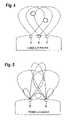
- FIG. 4shows a target situation with antenna characteristics of three radar sensors without switching of the antenna characteristics.
- FIG. 5shows the target situation of FIG. 4 using two radar sensors with switching of the antenna characteristics.
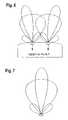
- FIG. 6shows antenna characteristics with two switchable radar sensors and antenna characteristics pointing outward with reference to the receiving antenna having a narrow beam width.
- FIG. 7shows a radar sensor with alignment of the antenna characteristics having a narrow beam width in the direction of the sensor axis.
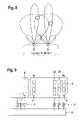
- FIG. 8shows antenna characteristics of two arrays of patch antennas.
- FIG. 9shows the configuration of a patch antenna array and the signal evaluation.
- FIG. 1shows an antenna arrangement of another system including a column 1 of four patch exciters for transmitting and a column 2 , separate therefrom, of four patch exciters for receiving.
- a single patch exciterhas a beam angle of about 90°.
- the vertical antenna beam angle(elevation) is reduced by the number of antenna elements.
- the four patch exciters of FIG. 1With the four patch exciters of FIG. 1 , a vertical beam angle of 30° is obtained. In the horizontal direction (the azimuth), nothing is altered with respect to a single exciter, i.e., the beam angle is 90°.
- the antenna characteristics associated with FIG. 1are shown in FIG. 2 . The antenna characteristics for transmitting and receiving in the azimuth are practically the same.
- beam shapingmay also be executed in the azimuth.
- the antenna diagrammay be swiveled when the individual columns are in addition controlled separately by signals displaceable in phase.
- phase shifters 3with unlike time lags may be provided for each column ( FIG. 9 , whose output signals are processed together in evaluation unit 4 , in order to determine the angular deviation from the receiving signals of the two radar sensors in unlike switching states).
- Switch-off or switch-on of antenna columnsmay be varied in the antenna diagram, i.e., the antenna characteristic. Two columns that are capable of being switched on and include four patch exciters each are shown in FIG. 9 .
- Switching the receiving antenna characteristicsmay allow the number of radar sensors to be reduced. Two different receiving antenna characteristics permit information concerning the angular deviation of a target to be obtained. Various target scenarios are shown in FIG. 3 . Thus, in addition to distance information, the angular deviation is obtained.
- the switchable antenna diagrams of the receiving antennas for separation of the two targetsare shown in FIG. 3 .
- FIG. 4shows the ACC-stop-and-go situation using three radar sensors without antenna switching. At least three radar sensors 5 , 6 , and 7 are required in order to be able to react specifically to two targets using triangulation.
- FIG. 5shows the same situation, controlled according to the present invention by two radar sensors 8 and 9 , specifically by configuring the receiving antennas of radar sensors 8 and 9 as switchable with reference to their main beam direction as well as to their beam width, in particular by switching antenna columns 2 , 21 , 22 on and off ( FIG. 9 ) and corresponding phase control.
- the two narrow lobesi.e., the antenna characteristics having a narrow beam width, are swiveled out of the sensor axis, i.e., toward the midperpendicular of the two radar sensors, in the direction of the center of the vehicle. An increase in range directly in front of the vehicle is thereby obtained.
- the arrangement in FIG. 5may provide for:
- the antenna columnsare switched on or off depending on the application. When additional columns are switched off, the radar sensors continue to be capable of delivering the same performance, as may be seen in FIG. 2 .
- FIG. 2There a variation of the known amplitude monopole method is shown with antenna lobes that are not swiveled.
- FIG. 6The case with lobes turned outward with reference to the narrow beam widths is shown in FIG. 6 .
- This arrangementpermits precise detection at the edges of the vehicle path in forward as well as in reverse direction. It is of course alternatively possible to align the narrow antenna lobes in the direction of the sensor axis ( FIG. 7 ).
- Two targetsmay be specifically allocated in combination with the second radar sensor ( FIG. 8 ).
- the increased gain of the antennaincreases the range of the radar sensor.
- switching of the antenna characteristics (lobes)permits optimal use of the radar sensor in the close range and in the far range.
- the antenna characteristicremains constant, so that the transmitting power need not be switched. This may be for approval reasons.
- the receiving antennaincludes an array of individual patches. Triggering of the antenna columns gives information concerning the mode of operation. Either the signal phases are switched and a swivelable antenna lobe is present, or the columns are switched on and a distinct change in the beam angle of the receiving antenna is present.
- the antenna system according to the present inventionmay be suitable for angular resolution in pulse radar applications of automotive technology, but alternatively may be used for other applications.
Landscapes
- Engineering & Computer Science (AREA)
- Radar, Positioning & Navigation (AREA)
- Remote Sensing (AREA)
- Computer Networks & Wireless Communication (AREA)
- Physics & Mathematics (AREA)
- General Physics & Mathematics (AREA)
- Variable-Direction Aerials And Aerial Arrays (AREA)
- Radar Systems Or Details Thereof (AREA)
Abstract
Description
The present invention relates to an angle-resolving antenna system.
Pulse radar systems may be used for the determination of the speed and distance of objects in street traffic, as in, for example, International Published Patent Application No. 99/42856.
German Published Patent Application No. 44 12 770 discusses that overlapping antenna lobes may be produced for a motor vehicle distance-warning radar in which the beam lobes may also be swiveled. Either an exciter system is used there as the transmitting and receiving antenna, or a separate transmitting and receiving antenna is provided.
International Published Patent Application No. 02/15334 discusses a multi-beam antenna array including a beam-shaping network and a beam-combining network. Measures are taken there to have the transmitting and receiving lobes point in exactly the same direction.
The present invention provides for two radar sensors for the determination of distance and angular deviation each including a separate transmitting and receiving antenna, receiving antennas for the two radar sensors switchable with reference to their main beam direction as well as to their beam width, and an evaluation arrangement for obtaining the angular deviation from the receiving signals of the two radar sensors in unlike switching states of their receiving antennas, may allow the number of radar sensors, in particular for the determination of angular deviation, to be reduced. Two different receiving antenna characteristics give information concerning the angular deviation of a target.
In addition to the evaluation of angular deviation using only two radar sensors, an increase in range is obtained. Switching, i.e., free selection of antenna characteristics with reference to their main beam direction and beam width, results in great flexibility for a variety of applications, e.g., ACC, TWD, PP, in the close and far range. When the additional antenna exciter arrays are switched off, the antenna system is still capable of delivering its usual performance.
If, as here, a plurality of patches, for example four patches, are located in a column, the vertical antenna beam angle (elevation) is reduced by the number of antenna elements. With the four patch exciters ofFIG. 1 , a vertical beam angle of 30° is obtained. In the horizontal direction (the azimuth), nothing is altered with respect to a single exciter, i.e., the beam angle is 90°. The antenna characteristics associated withFIG. 1 are shown inFIG. 2 . The antenna characteristics for transmitting and receiving in the azimuth are practically the same.
Now, if one or more columns are combined into one receiving-antenna array, beam shaping may also be executed in the azimuth. The antenna diagram may be swiveled when the individual columns are in addition controlled separately by signals displaceable in phase. For this purpose,phase shifters 3 with unlike time lags may be provided for each column (FIG. 9 , whose output signals are processed together in evaluation unit4, in order to determine the angular deviation from the receiving signals of the two radar sensors in unlike switching states). Switch-off or switch-on of antenna columns may be varied in the antenna diagram, i.e., the antenna characteristic. Two columns that are capable of being switched on and include four patch exciters each are shown inFIG. 9 .
Switching the receiving antenna characteristics may allow the number of radar sensors to be reduced. Two different receiving antenna characteristics permit information concerning the angular deviation of a target to be obtained. Various target scenarios are shown inFIG. 3 . Thus, in addition to distance information, the angular deviation is obtained. The switchable antenna diagrams of the receiving antennas for separation of the two targets are shown inFIG. 3 .
The arrangement inFIG. 5 may provide for:
- Rough angular resolution of a single sensor,
- Reduction in the number of radar sensors,
- Increase in range,
- Switching, i.e., free selection of the antenna characteristic, results in greater flexibility (ACC, TWD, PP).
The antenna columns are switched on or off depending on the application. When additional columns are switched off, the radar sensors continue to be capable of delivering the same performance, as may be seen inFIG. 2 . There a variation of the known amplitude monopole method is shown with antenna lobes that are not swiveled.
The case with lobes turned outward with reference to the narrow beam widths is shown inFIG. 6 . This arrangement permits precise detection at the edges of the vehicle path in forward as well as in reverse direction. It is of course alternatively possible to align the narrow antenna lobes in the direction of the sensor axis (FIG. 7 ). The same feature as described above is obtained by skillful selection methods. Two targets may be specifically allocated in combination with the second radar sensor (FIG. 8 ). The increased gain of the antenna increases the range of the radar sensor. In addition, switching of the antenna characteristics (lobes) permits optimal use of the radar sensor in the close range and in the far range. The antenna characteristic remains constant, so that the transmitting power need not be switched. This may be for approval reasons.
AsFIG. 9 shows, the receiving antenna includes an array of individual patches. Triggering of the antenna columns gives information concerning the mode of operation. Either the signal phases are switched and a swivelable antenna lobe is present, or the columns are switched on and a distinct change in the beam angle of the receiving antenna is present.
The antenna system according to the present invention may be suitable for angular resolution in pulse radar applications of automotive technology, but alternatively may be used for other applications.
Claims (5)
1. An angle-resolving antenna system for pulse radar applications in automotive technology, comprising:
two radar sensors for determination of distance information and angular deviation, each of the two radar sensors including a separate transmitting antenna and receiving antenna;
an evaluation unit for obtaining the angular deviation from receiving signals of the two radar sensors in unlike switching states; and
at least one column of antenna exciters that is capable of being switched on and off for switching the beam width;
wherein receiving antennas of the two radar sensors are configured to be switchable with regard to main beam direction and beam width.
2. The angle-resolving antenna system ofclaim 1 , wherein a phase control of at least two columns of antenna exciters for switching the main beam direction.
3. The angle-resolving antenna system ofclaim 1 , wherein the receiving antennas of the two radar sensors with a narrow beam width with reference to the main beam direction are directed outward away from a midperpendicular of the two radar sensors in order to obtain precise detection at edges of a vehicle path in at least one a forward direction and a reverse direction.
4. The angle-resolving antenna system ofclaim 1 , wherein the receiving antennas of the two radar sensors with a narrow beam width with reference to the main beam direction are inclined toward a midperpendicular of the two radar sensors in order to obtain an increased range in a driving direction.
5. An angle-resolving antenna system for pulse radar applications in automotive technology, comprising:
two radar sensors for determination of distance information and angular deviation, each of the two radar sensors including a separate transmitting antenna and receiving antenna;
an evaluation unit for obtaining the angular deviation from receiving signals of the two radar sensors in unlike switching states; and
plurality of receiving antenna exciters columns that are combined into one antenna array in order to achieve beam shaping in an azimuth direction;
wherein receiving antennas of the two radar sensors are configured to be switchable with regard to main beam direction and beam width.
Applications Claiming Priority (3)
| Application Number | Priority Date | Filing Date | Title |
|---|---|---|---|
| DE10261027.4 | 2002-12-24 | ||
| DE10261027ADE10261027A1 (en) | 2002-12-24 | 2002-12-24 | Angle-resolving antenna system |
| PCT/DE2003/003514WO2004061475A1 (en) | 2002-12-24 | 2003-10-22 | Angular resolution antenna system |
Publications (2)
| Publication Number | Publication Date |
|---|---|
| US20060164294A1 US20060164294A1 (en) | 2006-07-27 |
| US7268722B2true US7268722B2 (en) | 2007-09-11 |
Family
ID=32477996
Family Applications (1)
| Application Number | Title | Priority Date | Filing Date |
|---|---|---|---|
| US10/527,150Expired - Fee RelatedUS7268722B2 (en) | 2002-12-24 | 2003-10-22 | Angular resolution antenna system |
Country Status (5)
| Country | Link |
|---|---|
| US (1) | US7268722B2 (en) |
| EP (1) | EP1588190A1 (en) |
| JP (1) | JP2006512578A (en) |
| DE (1) | DE10261027A1 (en) |
| WO (1) | WO2004061475A1 (en) |
Cited By (48)
| Publication number | Priority date | Publication date | Assignee | Title |
|---|---|---|---|---|
| US20070080862A1 (en)* | 2003-11-08 | 2007-04-12 | Bernd Biehlman | Method for operating an antenna assembly |
| US20070222662A1 (en)* | 2004-01-29 | 2007-09-27 | Tore Toennesen | Radar System for Motor Vehicles |
| US20080258964A1 (en)* | 2004-12-13 | 2008-10-23 | Thomas Schoeberl | Radar System |
| US20100253568A1 (en)* | 2007-11-19 | 2010-10-07 | Robert Bosch Gmbh | Method for exchanging radar signals |
| US20110080313A1 (en)* | 2008-07-02 | 2011-04-07 | Adc Automotive Distance Control Systems Gmbh | Radar Sensor with Frontal and Lateral Emission |
| US20110199252A1 (en)* | 2007-06-19 | 2011-08-18 | Michael Klar | Sensor device having a variable azimuthal detection range for a motor vehicle |
| US20120038504A1 (en)* | 2010-08-11 | 2012-02-16 | Lockheed Martin Corporation | Enhanced-resolution phased array radar |
| US20120188117A1 (en)* | 2011-01-25 | 2012-07-26 | Mando Corporation | Detection sensor |
| US20120235857A1 (en)* | 2011-03-16 | 2012-09-20 | Electronics And Telecommunications Research Institute | Radar apparatus supporting short and long range radar operation |
| US20130187808A1 (en)* | 2012-01-19 | 2013-07-25 | Mando Corporation | Radar apparatus and antenna apparatus |
| US20130321196A1 (en)* | 2010-12-29 | 2013-12-05 | Robert Bosch Gmbh | Radar sensor for motor vehicles |
| US20140191895A1 (en)* | 2011-07-05 | 2014-07-10 | Thomas Binzer | Radar system for motor vehicles, and motor vehicle having a radar system |
| US9182476B2 (en) | 2009-04-06 | 2015-11-10 | Conti Temic Microelectronic Gmbh | Radar system having arrangements and methods for the decoupling of transmitting and receiving signals and for the suppression of interference radiation |
| US9838078B2 (en) | 2015-07-31 | 2017-12-05 | At&T Intellectual Property I, L.P. | Method and apparatus for exchanging communication signals |
| US9838896B1 (en) | 2016-12-09 | 2017-12-05 | At&T Intellectual Property I, L.P. | Method and apparatus for assessing network coverage |
| US9847850B2 (en) | 2014-10-14 | 2017-12-19 | At&T Intellectual Property I, L.P. | Method and apparatus for adjusting a mode of communication in a communication network |
| US9847566B2 (en) | 2015-07-14 | 2017-12-19 | At&T Intellectual Property I, L.P. | Method and apparatus for adjusting a field of a signal to mitigate interference |
| US9853342B2 (en) | 2015-07-14 | 2017-12-26 | At&T Intellectual Property I, L.P. | Dielectric transmission medium connector and methods for use therewith |
| US9860075B1 (en) | 2016-08-26 | 2018-01-02 | At&T Intellectual Property I, L.P. | Method and communication node for broadband distribution |
| US9865911B2 (en) | 2015-06-25 | 2018-01-09 | At&T Intellectual Property I, L.P. | Waveguide system for slot radiating first electromagnetic waves that are combined into a non-fundamental wave mode second electromagnetic wave on a transmission medium |
| US9871282B2 (en) | 2015-05-14 | 2018-01-16 | At&T Intellectual Property I, L.P. | At least one transmission medium having a dielectric surface that is covered at least in part by a second dielectric |
| US9871283B2 (en) | 2015-07-23 | 2018-01-16 | At&T Intellectual Property I, Lp | Transmission medium having a dielectric core comprised of plural members connected by a ball and socket configuration |
| US9876264B2 (en) | 2015-10-02 | 2018-01-23 | At&T Intellectual Property I, Lp | Communication system, guided wave switch and methods for use therewith |
| US9876587B2 (en) | 2014-10-21 | 2018-01-23 | At&T Intellectual Property I, L.P. | Transmission device with impairment compensation and methods for use therewith |
| US9887447B2 (en) | 2015-05-14 | 2018-02-06 | At&T Intellectual Property I, L.P. | Transmission medium having multiple cores and methods for use therewith |
| US9906269B2 (en)* | 2014-09-17 | 2018-02-27 | At&T Intellectual Property I, L.P. | Monitoring and mitigating conditions in a communication network |
| US9904535B2 (en) | 2015-09-14 | 2018-02-27 | At&T Intellectual Property I, L.P. | Method and apparatus for distributing software |
| US9913139B2 (en) | 2015-06-09 | 2018-03-06 | At&T Intellectual Property I, L.P. | Signal fingerprinting for authentication of communicating devices |
| US9912027B2 (en) | 2015-07-23 | 2018-03-06 | At&T Intellectual Property I, L.P. | Method and apparatus for exchanging communication signals |
| US9912382B2 (en) | 2015-06-03 | 2018-03-06 | At&T Intellectual Property I, Lp | Network termination and methods for use therewith |
| US9948333B2 (en) | 2015-07-23 | 2018-04-17 | At&T Intellectual Property I, L.P. | Method and apparatus for wireless communications to mitigate interference |
| US9967173B2 (en) | 2015-07-31 | 2018-05-08 | At&T Intellectual Property I, L.P. | Method and apparatus for authentication and identity management of communicating devices |
| US9997819B2 (en) | 2015-06-09 | 2018-06-12 | At&T Intellectual Property I, L.P. | Transmission medium and method for facilitating propagation of electromagnetic waves via a core |
| US10033098B2 (en)* | 2013-04-03 | 2018-07-24 | Robert Bosch Gmbh | Radar device and method having an antenna array with two switching states of different modulation |
| US10044409B2 (en) | 2015-07-14 | 2018-08-07 | At&T Intellectual Property I, L.P. | Transmission medium and methods for use therewith |
| US10069185B2 (en) | 2015-06-25 | 2018-09-04 | At&T Intellectual Property I, L.P. | Methods and apparatus for inducing a non-fundamental wave mode on a transmission medium |
| US10178445B2 (en) | 2016-11-23 | 2019-01-08 | At&T Intellectual Property I, L.P. | Methods, devices, and systems for load balancing between a plurality of waveguides |
| US10225025B2 (en) | 2016-11-03 | 2019-03-05 | At&T Intellectual Property I, L.P. | Method and apparatus for detecting a fault in a communication system |
| US10243784B2 (en) | 2014-11-20 | 2019-03-26 | At&T Intellectual Property I, L.P. | System for generating topology information and methods thereof |
| US10389037B2 (en) | 2016-12-08 | 2019-08-20 | At&T Intellectual Property I, L.P. | Apparatus and methods for selecting sections of an antenna array and use therewith |
| US10637149B2 (en) | 2016-12-06 | 2020-04-28 | At&T Intellectual Property I, L.P. | Injection molded dielectric antenna and methods for use therewith |
| US10650940B2 (en) | 2015-05-15 | 2020-05-12 | At&T Intellectual Property I, L.P. | Transmission medium having a conductive material and methods for use therewith |
| US10768288B2 (en)* | 2016-05-09 | 2020-09-08 | Robert Bosch Gmbh | Azimuth determination with the aid of a radar sensor |
| US10811767B2 (en) | 2016-10-21 | 2020-10-20 | At&T Intellectual Property I, L.P. | System and dielectric antenna with convex dielectric radome |
| US10823836B2 (en) | 2015-11-19 | 2020-11-03 | Conti Temic Microelectronic Gmbh | Radar system having interleaved serial transmitting and parallel receiving |
| US10840595B2 (en) | 2017-03-10 | 2020-11-17 | Flir Systems, Inc. | Conjoint beam shaping systems and methods |
| US20220003858A1 (en)* | 2018-09-27 | 2022-01-06 | Kyocera Corporation | Electronic apparatus, control method for electronic apparatus, and control program for electronic apparatus |
| US11435438B2 (en)* | 2019-12-30 | 2022-09-06 | Woven Planet North America, Inc. | Dynamic sparse radar array for scenarios |
Families Citing this family (26)
| Publication number | Priority date | Publication date | Assignee | Title |
|---|---|---|---|---|
| DE10348226A1 (en)* | 2003-10-10 | 2005-05-04 | Valeo Schalter & Sensoren Gmbh | Radar system with switchable angular resolution |
| DE10261027A1 (en)* | 2002-12-24 | 2004-07-08 | Robert Bosch Gmbh | Angle-resolving antenna system |
| JP2005156337A (en)* | 2003-11-26 | 2005-06-16 | Hitachi Ltd | Automotive radar equipment |
| EP1788408B1 (en)* | 2004-07-16 | 2014-03-05 | Fujitsu Ten, Ltd. | Mono pulse radar device and antenna selector switch |
| DE102004043358A1 (en)* | 2004-09-08 | 2006-03-09 | Robert Bosch Gmbh | Arrangement for regulating speed of vehicle has object detection sensing system with first long range detection region with increasing detection width with increasing distance, maximum width corresponding to vehicle lane |
| US7498970B2 (en)* | 2004-09-15 | 2009-03-03 | Panasonic Corporation | Monitor |
| DE102004054466A1 (en)* | 2004-11-11 | 2006-06-08 | Robert Bosch Gmbh | Radar system, in particular for distance and / or speed measurement |
| DE102005023432A1 (en)* | 2005-05-20 | 2006-11-30 | Valeo Schalter Und Sensoren Gmbh | Motor vehicle radar system and method for operating a motor vehicle radar system |
| US7474262B2 (en) | 2005-07-01 | 2009-01-06 | Delphi Technologies, Inc. | Digital beamforming for an electronically scanned radar system |
| CN101042435B (en) | 2006-03-23 | 2011-03-23 | 欧姆龙汽车电子株式会社 | Single pulse radar device |
| DE102006049879B4 (en)* | 2006-10-23 | 2021-02-18 | Robert Bosch Gmbh | Radar system for automobiles |
| US7755533B2 (en)* | 2006-11-01 | 2010-07-13 | Imsar Llc | Interferometric switched beam radar apparatus and method |
| JP4545174B2 (en)* | 2007-06-11 | 2010-09-15 | 三菱電機株式会社 | Radar equipment |
| DE102007056910A1 (en)* | 2007-11-26 | 2009-05-28 | Robert Bosch Gmbh | Method for operating an array-based beam-swiveling antenna and arrangement and use |
| DE102007061738A1 (en) | 2007-12-20 | 2009-06-25 | Robert Bosch Gmbh | Antenna, in particular for radar signals, and method and use |
| DE102007062566A1 (en)* | 2007-12-22 | 2009-07-02 | Audi Ag | motor vehicle |
| DE102012101303A1 (en)* | 2012-02-17 | 2013-08-22 | Hella Kgaa Hueck & Co. | sensor device |
| DE102012101363A1 (en)* | 2012-02-21 | 2013-08-22 | Hella Kgaa Hueck & Co. | Method for operating a circuit arrangement with a control and / or regulating means for a light-emitting diode array |
| KR20160081506A (en)* | 2014-12-31 | 2016-07-08 | 현대모비스 주식회사 | Alignment correction system and a control method of a radar and the side of the vehicle |
| KR102334415B1 (en)* | 2015-09-24 | 2021-12-03 | 엘지이노텍 주식회사 | Antenna apparatus and automotive radar apparatus having the same |
| DE102016005620A1 (en)* | 2016-05-06 | 2017-11-09 | Audi Ag | Motor vehicle with at least two radar sensors |
| EP3267220A1 (en)* | 2016-07-08 | 2018-01-10 | Autoliv Development AB | A vehicle radar system |
| EP3343244A1 (en)* | 2016-12-30 | 2018-07-04 | Nxp B.V. | Radar system |
| TWI691118B (en)* | 2019-02-11 | 2020-04-11 | 緯創資通股份有限公司 | Antenna system |
| DE102020119934A1 (en)* | 2020-07-29 | 2022-02-03 | Valeo Schalter Und Sensoren Gmbh | Method for operating a radar system, radar system and vehicle with at least one radar system |
| JP2024096619A (en)* | 2023-01-04 | 2024-07-17 | 株式会社東芝 | Radar Systems |
Citations (17)
| Publication number | Priority date | Publication date | Assignee | Title |
|---|---|---|---|---|
| GB2099256A (en)* | 1981-05-26 | 1982-12-01 | Ferranti Ltd | Bistatic radar |
| JPS6057281A (en)* | 1983-09-08 | 1985-04-03 | Mitsubishi Electric Corp | radar device |
| JPS62135785A (en)* | 1985-12-10 | 1987-06-18 | Mitsubishi Electric Corp | radar device |
| US5008678A (en)* | 1990-03-02 | 1991-04-16 | Hughes Aircraft Company | Electronically scanning vehicle radar sensor |
| JPH07167951A (en) | 1993-12-16 | 1995-07-04 | Honda Motor Co Ltd | Radar equipment |
| DE4412770A1 (en) | 1994-04-13 | 1995-10-19 | Siemens Ag | Microwave lens aerial for car distance warning radar |
| WO1999042856A2 (en) | 1998-02-19 | 1999-08-26 | Amerigon Inc. | High performance vehicle radar system |
| US6094160A (en)* | 1999-06-10 | 2000-07-25 | Delco Electronics Corp. | Interference rejection method for an automotive radar CW/ICC system |
| US6137434A (en) | 1996-05-02 | 2000-10-24 | Honda Giken Kogyo Kabushiki Kaisha | Multibeam radar system |
| WO2002015334A1 (en) | 2000-08-16 | 2002-02-21 | Raytheon Company | Switched beam antenna architecture |
| DE10056002A1 (en) | 2000-11-11 | 2002-05-23 | Bosch Gmbh Robert | Radar device has received echo pulses split between at least 2 reception paths controlled for providing different directional characteristics |
| US20020067314A1 (en)* | 2000-09-27 | 2002-06-06 | Murata Manufacturing Co., Ltd. | Antenna device, communication apparatus and radar module |
| US6433741B2 (en)* | 1998-07-07 | 2002-08-13 | Murata Manufacturing Co., Ltd. | Directional coupler, antenna device, and transmitting-receiving device |
| US20040036645A1 (en)* | 2002-08-22 | 2004-02-26 | Hitachi, Ltd. | Millimeter wave radar |
| US6750810B2 (en)* | 2001-12-18 | 2004-06-15 | Hitachi, Ltd. | Monopulse radar system |
| US20040119633A1 (en)* | 2000-02-08 | 2004-06-24 | Cambridge Consultants Limited | Methods and apparatus for obtaining positional information |
| US20060164294A1 (en)* | 2002-12-24 | 2006-07-27 | Frank Gottwald | Angular resolution antenna system |
Family Cites Families (2)
| Publication number | Priority date | Publication date | Assignee | Title |
|---|---|---|---|---|
| JP3602259B2 (en)* | 1996-05-02 | 2004-12-15 | 本田技研工業株式会社 | Multi-beam radar equipment |
| JP3602258B2 (en)* | 1996-05-02 | 2004-12-15 | 本田技研工業株式会社 | Multi-beam radar antenna |
- 2002
- 2002-12-24DEDE10261027Apatent/DE10261027A1/ennot_activeWithdrawn
- 2003
- 2003-10-22EPEP03773562Apatent/EP1588190A1/ennot_activeWithdrawn
- 2003-10-22WOPCT/DE2003/003514patent/WO2004061475A1/enactiveApplication Filing
- 2003-10-22USUS10/527,150patent/US7268722B2/ennot_activeExpired - Fee Related
- 2003-10-22JPJP2004564146Apatent/JP2006512578A/enactivePending
Patent Citations (17)
| Publication number | Priority date | Publication date | Assignee | Title |
|---|---|---|---|---|
| GB2099256A (en)* | 1981-05-26 | 1982-12-01 | Ferranti Ltd | Bistatic radar |
| JPS6057281A (en)* | 1983-09-08 | 1985-04-03 | Mitsubishi Electric Corp | radar device |
| JPS62135785A (en)* | 1985-12-10 | 1987-06-18 | Mitsubishi Electric Corp | radar device |
| US5008678A (en)* | 1990-03-02 | 1991-04-16 | Hughes Aircraft Company | Electronically scanning vehicle radar sensor |
| JPH07167951A (en) | 1993-12-16 | 1995-07-04 | Honda Motor Co Ltd | Radar equipment |
| DE4412770A1 (en) | 1994-04-13 | 1995-10-19 | Siemens Ag | Microwave lens aerial for car distance warning radar |
| US6137434A (en) | 1996-05-02 | 2000-10-24 | Honda Giken Kogyo Kabushiki Kaisha | Multibeam radar system |
| WO1999042856A2 (en) | 1998-02-19 | 1999-08-26 | Amerigon Inc. | High performance vehicle radar system |
| US6433741B2 (en)* | 1998-07-07 | 2002-08-13 | Murata Manufacturing Co., Ltd. | Directional coupler, antenna device, and transmitting-receiving device |
| US6094160A (en)* | 1999-06-10 | 2000-07-25 | Delco Electronics Corp. | Interference rejection method for an automotive radar CW/ICC system |
| US20040119633A1 (en)* | 2000-02-08 | 2004-06-24 | Cambridge Consultants Limited | Methods and apparatus for obtaining positional information |
| WO2002015334A1 (en) | 2000-08-16 | 2002-02-21 | Raytheon Company | Switched beam antenna architecture |
| US20020067314A1 (en)* | 2000-09-27 | 2002-06-06 | Murata Manufacturing Co., Ltd. | Antenna device, communication apparatus and radar module |
| DE10056002A1 (en) | 2000-11-11 | 2002-05-23 | Bosch Gmbh Robert | Radar device has received echo pulses split between at least 2 reception paths controlled for providing different directional characteristics |
| US6750810B2 (en)* | 2001-12-18 | 2004-06-15 | Hitachi, Ltd. | Monopulse radar system |
| US20040036645A1 (en)* | 2002-08-22 | 2004-02-26 | Hitachi, Ltd. | Millimeter wave radar |
| US20060164294A1 (en)* | 2002-12-24 | 2006-07-27 | Frank Gottwald | Angular resolution antenna system |
Non-Patent Citations (2)
| Title |
|---|
| "Multi-beam automotive radar front end using non-contact cylindrical NRD switch", Tanizaki, T.; Nishida, H.; Nishiyama, T.; Yamada, H.; Sakamoto, K.; Ishikawa, Y. Microwave Symposium Digest, 1998 IEEE MTT-S Int'l vol. 2, Jun. 7-12, 1998 Ps:521-524.* |
| Patent Abstracts of Japan, vol. 1995, No. 10, Nov. 30, 1995. |
Cited By (62)
| Publication number | Priority date | Publication date | Assignee | Title |
|---|---|---|---|---|
| US20070080862A1 (en)* | 2003-11-08 | 2007-04-12 | Bernd Biehlman | Method for operating an antenna assembly |
| US20070222662A1 (en)* | 2004-01-29 | 2007-09-27 | Tore Toennesen | Radar System for Motor Vehicles |
| US7663533B2 (en)* | 2004-01-29 | 2010-02-16 | Robert Bosch Gmbh | Radar system for motor vehicles |
| US20080258964A1 (en)* | 2004-12-13 | 2008-10-23 | Thomas Schoeberl | Radar System |
| US20110199252A1 (en)* | 2007-06-19 | 2011-08-18 | Michael Klar | Sensor device having a variable azimuthal detection range for a motor vehicle |
| US20100253568A1 (en)* | 2007-11-19 | 2010-10-07 | Robert Bosch Gmbh | Method for exchanging radar signals |
| US8436763B2 (en) | 2008-07-02 | 2013-05-07 | Adc Automotive Distance Control Systems Gmbh | Radar system comprising overlapping transmitter and receiver antennas |
| US8593333B2 (en)* | 2008-07-02 | 2013-11-26 | Adc Automotive Distance Control Systems Gmbh | Radar sensor with frontal and lateral emission |
| US20110080313A1 (en)* | 2008-07-02 | 2011-04-07 | Adc Automotive Distance Control Systems Gmbh | Radar Sensor with Frontal and Lateral Emission |
| US8665137B2 (en) | 2008-07-02 | 2014-03-04 | Adc Automotive Distance Control Systems Gmbh | Radar system with improved angle formation |
| US9182476B2 (en) | 2009-04-06 | 2015-11-10 | Conti Temic Microelectronic Gmbh | Radar system having arrangements and methods for the decoupling of transmitting and receiving signals and for the suppression of interference radiation |
| US8736484B2 (en)* | 2010-08-11 | 2014-05-27 | Lockheed Martin Corporation | Enhanced-resolution phased array radar |
| US20120038504A1 (en)* | 2010-08-11 | 2012-02-16 | Lockheed Martin Corporation | Enhanced-resolution phased array radar |
| US20130321196A1 (en)* | 2010-12-29 | 2013-12-05 | Robert Bosch Gmbh | Radar sensor for motor vehicles |
| US9638796B2 (en)* | 2010-12-29 | 2017-05-02 | Robert Bosch Gmbh | Radar sensor for motor vehicles |
| US9035818B2 (en)* | 2011-01-25 | 2015-05-19 | Mando Corporation | Detection sensor |
| US20120188117A1 (en)* | 2011-01-25 | 2012-07-26 | Mando Corporation | Detection sensor |
| US8902103B2 (en)* | 2011-03-16 | 2014-12-02 | Electronics And Telecommunications Research Institute | Radar apparatus supporting short and long range radar operation |
| US20120235857A1 (en)* | 2011-03-16 | 2012-09-20 | Electronics And Telecommunications Research Institute | Radar apparatus supporting short and long range radar operation |
| US10018713B2 (en)* | 2011-07-05 | 2018-07-10 | Robert Bosch Gmbh | Radar system for motor vehicles, and motor vehicle having a radar system |
| US20140191895A1 (en)* | 2011-07-05 | 2014-07-10 | Thomas Binzer | Radar system for motor vehicles, and motor vehicle having a radar system |
| US20130187808A1 (en)* | 2012-01-19 | 2013-07-25 | Mando Corporation | Radar apparatus and antenna apparatus |
| US10033098B2 (en)* | 2013-04-03 | 2018-07-24 | Robert Bosch Gmbh | Radar device and method having an antenna array with two switching states of different modulation |
| US10075212B2 (en) | 2014-09-17 | 2018-09-11 | At&T Intellectual Property I, L.P. | Monitoring and mitigating conditions in a communication network |
| US10361750B2 (en) | 2014-09-17 | 2019-07-23 | At&T Intellectual Property I, L.P. | Monitoring and mitigating conditions in a communication network |
| US10135491B2 (en) | 2014-09-17 | 2018-11-20 | At&T Intellectual Property I, L.P. | Monitoring and mitigating conditions in a communication network |
| US10063280B2 (en) | 2014-09-17 | 2018-08-28 | At&T Intellectual Property I, L.P. | Monitoring and mitigating conditions in a communication network |
| US9906269B2 (en)* | 2014-09-17 | 2018-02-27 | At&T Intellectual Property I, L.P. | Monitoring and mitigating conditions in a communication network |
| US9847850B2 (en) | 2014-10-14 | 2017-12-19 | At&T Intellectual Property I, L.P. | Method and apparatus for adjusting a mode of communication in a communication network |
| US9876587B2 (en) | 2014-10-21 | 2018-01-23 | At&T Intellectual Property I, L.P. | Transmission device with impairment compensation and methods for use therewith |
| US10243784B2 (en) | 2014-11-20 | 2019-03-26 | At&T Intellectual Property I, L.P. | System for generating topology information and methods thereof |
| US9887447B2 (en) | 2015-05-14 | 2018-02-06 | At&T Intellectual Property I, L.P. | Transmission medium having multiple cores and methods for use therewith |
| US9871282B2 (en) | 2015-05-14 | 2018-01-16 | At&T Intellectual Property I, L.P. | At least one transmission medium having a dielectric surface that is covered at least in part by a second dielectric |
| US10650940B2 (en) | 2015-05-15 | 2020-05-12 | At&T Intellectual Property I, L.P. | Transmission medium having a conductive material and methods for use therewith |
| US9912382B2 (en) | 2015-06-03 | 2018-03-06 | At&T Intellectual Property I, Lp | Network termination and methods for use therewith |
| US9997819B2 (en) | 2015-06-09 | 2018-06-12 | At&T Intellectual Property I, L.P. | Transmission medium and method for facilitating propagation of electromagnetic waves via a core |
| US9913139B2 (en) | 2015-06-09 | 2018-03-06 | At&T Intellectual Property I, L.P. | Signal fingerprinting for authentication of communicating devices |
| US9865911B2 (en) | 2015-06-25 | 2018-01-09 | At&T Intellectual Property I, L.P. | Waveguide system for slot radiating first electromagnetic waves that are combined into a non-fundamental wave mode second electromagnetic wave on a transmission medium |
| US10069185B2 (en) | 2015-06-25 | 2018-09-04 | At&T Intellectual Property I, L.P. | Methods and apparatus for inducing a non-fundamental wave mode on a transmission medium |
| US10044409B2 (en) | 2015-07-14 | 2018-08-07 | At&T Intellectual Property I, L.P. | Transmission medium and methods for use therewith |
| US9847566B2 (en) | 2015-07-14 | 2017-12-19 | At&T Intellectual Property I, L.P. | Method and apparatus for adjusting a field of a signal to mitigate interference |
| US9853342B2 (en) | 2015-07-14 | 2017-12-26 | At&T Intellectual Property I, L.P. | Dielectric transmission medium connector and methods for use therewith |
| US9948333B2 (en) | 2015-07-23 | 2018-04-17 | At&T Intellectual Property I, L.P. | Method and apparatus for wireless communications to mitigate interference |
| US9912027B2 (en) | 2015-07-23 | 2018-03-06 | At&T Intellectual Property I, L.P. | Method and apparatus for exchanging communication signals |
| US9871283B2 (en) | 2015-07-23 | 2018-01-16 | At&T Intellectual Property I, Lp | Transmission medium having a dielectric core comprised of plural members connected by a ball and socket configuration |
| US9967173B2 (en) | 2015-07-31 | 2018-05-08 | At&T Intellectual Property I, L.P. | Method and apparatus for authentication and identity management of communicating devices |
| US9838078B2 (en) | 2015-07-31 | 2017-12-05 | At&T Intellectual Property I, L.P. | Method and apparatus for exchanging communication signals |
| US9904535B2 (en) | 2015-09-14 | 2018-02-27 | At&T Intellectual Property I, L.P. | Method and apparatus for distributing software |
| US9876264B2 (en) | 2015-10-02 | 2018-01-23 | At&T Intellectual Property I, Lp | Communication system, guided wave switch and methods for use therewith |
| US10823836B2 (en) | 2015-11-19 | 2020-11-03 | Conti Temic Microelectronic Gmbh | Radar system having interleaved serial transmitting and parallel receiving |
| US10768288B2 (en)* | 2016-05-09 | 2020-09-08 | Robert Bosch Gmbh | Azimuth determination with the aid of a radar sensor |
| US9860075B1 (en) | 2016-08-26 | 2018-01-02 | At&T Intellectual Property I, L.P. | Method and communication node for broadband distribution |
| US10811767B2 (en) | 2016-10-21 | 2020-10-20 | At&T Intellectual Property I, L.P. | System and dielectric antenna with convex dielectric radome |
| US10225025B2 (en) | 2016-11-03 | 2019-03-05 | At&T Intellectual Property I, L.P. | Method and apparatus for detecting a fault in a communication system |
| US10178445B2 (en) | 2016-11-23 | 2019-01-08 | At&T Intellectual Property I, L.P. | Methods, devices, and systems for load balancing between a plurality of waveguides |
| US10637149B2 (en) | 2016-12-06 | 2020-04-28 | At&T Intellectual Property I, L.P. | Injection molded dielectric antenna and methods for use therewith |
| US10389037B2 (en) | 2016-12-08 | 2019-08-20 | At&T Intellectual Property I, L.P. | Apparatus and methods for selecting sections of an antenna array and use therewith |
| US9838896B1 (en) | 2016-12-09 | 2017-12-05 | At&T Intellectual Property I, L.P. | Method and apparatus for assessing network coverage |
| US10840595B2 (en) | 2017-03-10 | 2020-11-17 | Flir Systems, Inc. | Conjoint beam shaping systems and methods |
| US20220003858A1 (en)* | 2018-09-27 | 2022-01-06 | Kyocera Corporation | Electronic apparatus, control method for electronic apparatus, and control program for electronic apparatus |
| US11874364B2 (en)* | 2018-09-27 | 2024-01-16 | Kyocera Corporation | Electronic apparatus, control method for electronic apparatus, and control program for electronic apparatus |
| US11435438B2 (en)* | 2019-12-30 | 2022-09-06 | Woven Planet North America, Inc. | Dynamic sparse radar array for scenarios |
Also Published As
| Publication number | Publication date |
|---|---|
| WO2004061475A1 (en) | 2004-07-22 |
| US20060164294A1 (en) | 2006-07-27 |
| DE10261027A1 (en) | 2004-07-08 |
| EP1588190A1 (en) | 2005-10-26 |
| JP2006512578A (en) | 2006-04-13 |
Similar Documents
| Publication | Publication Date | Title |
|---|---|---|
| US7268722B2 (en) | Angular resolution antenna system | |
| KR101880322B1 (en) | Radar sensor for motor vehicles | |
| EP1742081B1 (en) | Digital beamforming for an electronically scanned radar system | |
| US10197671B2 (en) | Virtual radar configuration for 2D array | |
| US7737879B2 (en) | Split aperture array for increased short range target coverage | |
| US8405541B2 (en) | Multi-range radar system | |
| US5949365A (en) | Multiple-beam radar system | |
| US7486223B2 (en) | Radar apparatus | |
| US20130088393A1 (en) | Transmit and receive phased array for automotive radar improvement | |
| US7864099B2 (en) | Low cost short range radar | |
| JP2003248055A (en) | Monopulse radar system | |
| US7321332B2 (en) | Device for measuring angle positions | |
| US11349202B2 (en) | Antenna device and radar including the same | |
| US20190072659A1 (en) | Artificial-Intelligence Controlled Adaptive Multi-Purpose Beam Forming Automobile Radar | |
| US7119733B2 (en) | Angle-scanning radar system | |
| CA2507636A1 (en) | A method for controlling a radar antenna | |
| EP3968053A1 (en) | Time division multiplexed monopulse aesa comparator network | |
| US20100271278A1 (en) | Bistatic array antenna and method | |
| US8482454B2 (en) | Monostatic multi-beam radar sensor, as well as method | |
| CN101520507B (en) | Ow cost short range radar | |
| KR102317250B1 (en) | Multi mode radar module | |
| KR20220165353A (en) | Radar apparatus | |
| US20230140503A1 (en) | Radar device and radar method | |
| US12117554B2 (en) | Radar module using multiple polarizations | |
| CN115047410B (en) | Radar radio frequency signal transmission control method, control module and radar |
Legal Events
| Date | Code | Title | Description |
|---|---|---|---|
| AS | Assignment | Owner name:ROBERT BOSCH GMBH, GERMANY Free format text:ASSIGNMENT OF ASSIGNORS INTEREST;ASSIGNORS:GOTTWALD, FRANK;SCHLICK, MICHAEL;REEL/FRAME:016934/0163;SIGNING DATES FROM 20050202 TO 20050221 | |
| REMI | Maintenance fee reminder mailed | ||
| LAPS | Lapse for failure to pay maintenance fees | ||
| STCH | Information on status: patent discontinuation | Free format text:PATENT EXPIRED DUE TO NONPAYMENT OF MAINTENANCE FEES UNDER 37 CFR 1.362 | |
| FP | Lapsed due to failure to pay maintenance fee | Effective date:20110911 |