US7268014B2 - Fabrication method of light emitting diode package - Google Patents
Fabrication method of light emitting diode packageDownload PDFInfo
- Publication number
- US7268014B2 US7268014B2US11/314,003US31400305AUS7268014B2US 7268014 B2US7268014 B2US 7268014B2US 31400305 AUS31400305 AUS 31400305AUS 7268014 B2US7268014 B2US 7268014B2
- Authority
- US
- United States
- Prior art keywords
- package
- light emitting
- package substrate
- fabrication method
- substrate
- Prior art date
- Legal status (The legal status is an assumption and is not a legal conclusion. Google has not performed a legal analysis and makes no representation as to the accuracy of the status listed.)
- Active
Links
Images


Classifications
- H—ELECTRICITY
- H10—SEMICONDUCTOR DEVICES; ELECTRIC SOLID-STATE DEVICES NOT OTHERWISE PROVIDED FOR
- H10H—INORGANIC LIGHT-EMITTING SEMICONDUCTOR DEVICES HAVING POTENTIAL BARRIERS
- H10H20/00—Individual inorganic light-emitting semiconductor devices having potential barriers, e.g. light-emitting diodes [LED]
- H10H20/80—Constructional details
- H10H20/85—Packages
- H10H20/858—Means for heat extraction or cooling
- H10H20/8585—Means for heat extraction or cooling being an interconnection
- H—ELECTRICITY
- H01—ELECTRIC ELEMENTS
- H01L—SEMICONDUCTOR DEVICES NOT COVERED BY CLASS H10
- H01L24/00—Arrangements for connecting or disconnecting semiconductor or solid-state bodies; Methods or apparatus related thereto
- H01L24/93—Batch processes
- H01L24/95—Batch processes at chip-level, i.e. with connecting carried out on a plurality of singulated devices, i.e. on diced chips
- H01L24/97—Batch processes at chip-level, i.e. with connecting carried out on a plurality of singulated devices, i.e. on diced chips the devices being connected to a common substrate, e.g. interposer, said common substrate being separable into individual assemblies after connecting
- H—ELECTRICITY
- H10—SEMICONDUCTOR DEVICES; ELECTRIC SOLID-STATE DEVICES NOT OTHERWISE PROVIDED FOR
- H10H—INORGANIC LIGHT-EMITTING SEMICONDUCTOR DEVICES HAVING POTENTIAL BARRIERS
- H10H20/00—Individual inorganic light-emitting semiconductor devices having potential barriers, e.g. light-emitting diodes [LED]
- H10H20/80—Constructional details
- H10H20/85—Packages
- H10H20/8506—Containers
- H—ELECTRICITY
- H01—ELECTRIC ELEMENTS
- H01L—SEMICONDUCTOR DEVICES NOT COVERED BY CLASS H10
- H01L2224/00—Indexing scheme for arrangements for connecting or disconnecting semiconductor or solid-state bodies and methods related thereto as covered by H01L24/00
- H01L2224/01—Means for bonding being attached to, or being formed on, the surface to be connected, e.g. chip-to-package, die-attach, "first-level" interconnects; Manufacturing methods related thereto
- H01L2224/10—Bump connectors; Manufacturing methods related thereto
- H01L2224/15—Structure, shape, material or disposition of the bump connectors after the connecting process
- H01L2224/16—Structure, shape, material or disposition of the bump connectors after the connecting process of an individual bump connector
- H01L2224/161—Disposition
- H01L2224/16151—Disposition the bump connector connecting between a semiconductor or solid-state body and an item not being a semiconductor or solid-state body, e.g. chip-to-substrate, chip-to-passive
- H01L2224/16221—Disposition the bump connector connecting between a semiconductor or solid-state body and an item not being a semiconductor or solid-state body, e.g. chip-to-substrate, chip-to-passive the body and the item being stacked
- H01L2224/16245—Disposition the bump connector connecting between a semiconductor or solid-state body and an item not being a semiconductor or solid-state body, e.g. chip-to-substrate, chip-to-passive the body and the item being stacked the item being metallic
- H—ELECTRICITY
- H01—ELECTRIC ELEMENTS
- H01L—SEMICONDUCTOR DEVICES NOT COVERED BY CLASS H10
- H01L2224/00—Indexing scheme for arrangements for connecting or disconnecting semiconductor or solid-state bodies and methods related thereto as covered by H01L24/00
- H01L2224/01—Means for bonding being attached to, or being formed on, the surface to be connected, e.g. chip-to-package, die-attach, "first-level" interconnects; Manufacturing methods related thereto
- H01L2224/42—Wire connectors; Manufacturing methods related thereto
- H01L2224/47—Structure, shape, material or disposition of the wire connectors after the connecting process
- H01L2224/48—Structure, shape, material or disposition of the wire connectors after the connecting process of an individual wire connector
- H01L2224/481—Disposition
- H01L2224/48151—Connecting between a semiconductor or solid-state body and an item not being a semiconductor or solid-state body, e.g. chip-to-substrate, chip-to-passive
- H01L2224/48221—Connecting between a semiconductor or solid-state body and an item not being a semiconductor or solid-state body, e.g. chip-to-substrate, chip-to-passive the body and the item being stacked
- H01L2224/48245—Connecting between a semiconductor or solid-state body and an item not being a semiconductor or solid-state body, e.g. chip-to-substrate, chip-to-passive the body and the item being stacked the item being metallic
- H01L2224/48247—Connecting between a semiconductor or solid-state body and an item not being a semiconductor or solid-state body, e.g. chip-to-substrate, chip-to-passive the body and the item being stacked the item being metallic connecting the wire to a bond pad of the item
- H—ELECTRICITY
- H01—ELECTRIC ELEMENTS
- H01L—SEMICONDUCTOR DEVICES NOT COVERED BY CLASS H10
- H01L2924/00—Indexing scheme for arrangements or methods for connecting or disconnecting semiconductor or solid-state bodies as covered by H01L24/00
- H01L2924/013—Alloys
- H01L2924/0132—Binary Alloys
- H01L2924/01322—Eutectic Alloys, i.e. obtained by a liquid transforming into two solid phases
- H—ELECTRICITY
- H01—ELECTRIC ELEMENTS
- H01L—SEMICONDUCTOR DEVICES NOT COVERED BY CLASS H10
- H01L2924/00—Indexing scheme for arrangements or methods for connecting or disconnecting semiconductor or solid-state bodies as covered by H01L24/00
- H01L2924/10—Details of semiconductor or other solid state devices to be connected
- H01L2924/11—Device type
- H01L2924/12—Passive devices, e.g. 2 terminal devices
- H01L2924/1204—Optical Diode
- H01L2924/12041—LED
- H—ELECTRICITY
- H10—SEMICONDUCTOR DEVICES; ELECTRIC SOLID-STATE DEVICES NOT OTHERWISE PROVIDED FOR
- H10H—INORGANIC LIGHT-EMITTING SEMICONDUCTOR DEVICES HAVING POTENTIAL BARRIERS
- H10H20/00—Individual inorganic light-emitting semiconductor devices having potential barriers, e.g. light-emitting diodes [LED]
- H10H20/01—Manufacture or treatment
- H10H20/036—Manufacture or treatment of packages
- H10H20/0365—Manufacture or treatment of packages of means for heat extraction or cooling
- H—ELECTRICITY
- H10—SEMICONDUCTOR DEVICES; ELECTRIC SOLID-STATE DEVICES NOT OTHERWISE PROVIDED FOR
- H10H—INORGANIC LIGHT-EMITTING SEMICONDUCTOR DEVICES HAVING POTENTIAL BARRIERS
- H10H20/00—Individual inorganic light-emitting semiconductor devices having potential barriers, e.g. light-emitting diodes [LED]
- H10H20/80—Constructional details
- H10H20/85—Packages
- H10H20/857—Interconnections, e.g. lead-frames, bond wires or solder balls
Definitions
- the present inventionrelates to a fabrication method of a light emitting diode package, more particularly, which can achieve excellent heat radiation as well as facilitate mass production.
- LEDLight Emitting Diode
- compound semiconductor materialsuch as GaAs, GaN and AlGaInP
- Decisive factors of LED propertiesmay include color, brightness and optical conversion efficiency. While such LED properties are primarily determined by compound semiconductor material and its internal structure used for an LED device, a package structure for housing the LED device acts as a secondary factor, giving great influence on the LED properties. In order to realize light emitting efficiency to such a degree that can satisfy user demand, it is necessary to improve not only first factors such as the material and structure of an LED device but also secondary factors such as an LED package structure and its material.
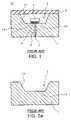
- FIG. 1is a cross-sectional view schematically illustrating the structure of a conventional LED package 10 .
- the LED package 10includes a package substrate 1 made of metal.
- the package substrate 1is divided into two package electrodes 1 a and 1 b by a slot 6 where insulator 2 of for example epoxy resin and so on is filled.
- the package substrate 1has a recess 3 , such that an LED device 7 is flip-chip bonded onto the package electrodes 1 a and 1 b at the bottom of the recess 3 .
- Underfill resin 4is filled between the LED device 7 and the bottom of the recess 3 .
- a cover panel 9 made of glassis bonded onto the top of the package substrate 1 .
- Sidewall of the recess 3forms a reflector surface 1 c , which reflects light propagating in lateral direction to redirect it in upward direction.
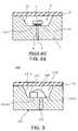
- FIGS. 2 a to 2 dare cross-sectional views illustrating a fabrication process of an LED package as shown in FIG. 1 .
- a package substrate 1 having a reflector surface 1 c in a recess 3is formed by molding or press molding of metal.
- a slot 6is formed in the package substrate 1 , dividing it into two package electrodes 1 a and 1 b .
- the slot 6is formed by machining such as press trimming or laser processing.
- Insulator 2 of for example epoxy resinis filled into the slot 6 , and through flip-chip bonding, an LED device 7 is mounted on the package electrodes 1 a and 1 b at the bottom of the recess 3 as shown in FIG.
- the package substrate 1is made of metal, it can effectively radiate heat from the LED device 7 .
- a metal substratei.e., package substrate
- insulator 2has to be filled into the narrow slot 6 .
- the present inventionhas been made to solve the foregoing problems of the prior art and it is therefore an object of the present invention to provide a fabrication method of an LED package, by which LED packages of excellent heat radiation characteristics can be fabricated more easily and precisely.
- the inventionprovides a fabrication method of a light emitting diode package, comprising steps of: preparing a metallic package substrate having a recess and a reflecting surface formed in the recess; selectively anodizing the package substrate into two package electrode parts divided from each other; and mounting an light emitting device on a bottom of the recess.
- the package substrateis made of Al or Al-based metal.
- the package substrate preparing stepmay comprise: providing a mask pattern on a metal substrate; selectively anodizing the metal substrate by using the mask pattern to form an anodic oxide region in the metal substrate; and etching the anodic oxide region to produce the recess in the metal substrate.
- the mask patternmay be formed to expose a predetermined top surface area of the metal substrate and cover an underside of the metal substrate, in which the predetermined top area of the metal substrate corresponds to an area where an anodic oxide region will be formed to provide the recess.
- said package substrate preparing stepmay comprise: producing the package substrate by injection molding or press molding of metal.
- said package substrate preparing stepmay comprise: forming an etching mask pattern on a metal substrate; and selectively etching the metal substrate by using the etching mask pattern to form the recess in the metal substrate.
- said package substrate anodizing stepmay comprise: forming a mask pattern on the package substrate; and selectively anodizing the package substrate by using the mask pattern to form an oxide membrane in the package substrate, the oxide membrane dividing the package substrate into the electrode parts.
- the mask patternmay be formed to expose a predetermined underside area of the package substrate and cover a top surface of the package substrate in which the predetermined top area of the metal substrate corresponds to an area where an anodic oxide region will be formed to provide the recess.
- said light emitting device mounting stepmay comprise: connecting the light emitting device to one of the package electrode parts by die bonding; and connecting the light emitting device to the other package electrode part at the bottom of the recess by wire bonding.
- said light emitting device mounting stepmay comprise: connecting the light emitting device to the package electrode parts by wire bonding of two wires.
- said light emitting device mounting stepmay comprise: flip-chip bonding the light emitting device on the package electrode parts at the bottom of the recess.
- a reflective metal filmmay be formed on a side surface of the recess before said light emitting device mounting step.
- the metal film formed on the side surfacemay be made of Au, Ag, Ti or Al to form a light-reflecting surface of high reflectivity on the side surface of the recess.
- the fabrication methodmay further comprise a step of: surface-treating the bottom of the recess with metal selected from a group consisting of Au, Ag and Al before said light emitting device mounting step in order to facilitate mounting of the light emitting device.
- the bottom of the recessmay be plated with for example Ag or printed with Ag containing ink by ink-jet printing. Such surface treatment on the recess bottom can provide a surface adequate for bonding of the light emitting device.
- the fabrication methodmay further comprise a step of: surface-treating the bottom of the package substrate by Au or Ag plating before said light emitting device mounting step.
- Such surface treatment on the recess bottomcan provide a surface adequate for bonding of the light emitting device.
- an optical elementsuch as a glass panel, convex lens or concave lens may be bonded to a top of the package substrate after said light emitting device mounting step.
- the optical elementmay act as a cover plate to seal the light emitting device.
- the fabrication method of the inventioncan be easily applied to bulk production of a number of LED packages in an LED package array. That is, the invention provides means for producing an LED package array in which a number of LED packages are arranged from a metal plate (or wafer level metal substrate). By severing the LED package array, a number of individual LED packages can be produced simultaneously.
- FIG. 1is a cross-sectional view illustrating a conventional LED package
- FIGS. 2 a to 2 dare cross-sectional views illustrating a fabrication process of a conventional LED package
- FIG. 3is a cross-sectional view illustrating an LED package fabricated according to an embodiment of the invention.
- FIG. 4is a plan view of the LED package shown in FIG. 4 ;
- FIG. 5is a cross-sectional view illustrating an LED package fabricated according to another embodiment of the invention.
- FIG. 6is a cross-sectional view illustrating an LED package fabricated according to further another embodiment of the invention.
- FIGS. 7 to 14are cross-sectional views illustrating a fabrication process of an LED package according to an embodiment of the invention.
- FIG. 15is a cross-sectional view illustrating an LED package array fabricated according to an embodiment of the invention.
- FIGS. 16 and 17are cross-sectional views illustrating a fabrication process of an LED package according to further another embodiment of the invention.
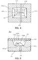
- FIG. 3is a cross-sectional view illustrating an LED package 100 fabricated according to an embodiment of the invention
- FIG. 4is a plan view of the LED package 100 shown in FIG. 4
- the LED package 100includes a vertical LED device 107 and a metallic package substrate 101 .
- the package substrate 101is an Al substrate or an Al-based metal substrate.
- the package substrate 101has a recess 103 that provides a mounting space for an LED device as well as a light-reflecting surface. Accordingly, in the LED package 100 , a light-reflecting part and a substrate part (submount part) are made integral.
- a reflective film made of for example Au, Ag or Alis coated on the side surface of the recess 103 , thereby forming a reflecting surface 101 c of high reflectivity.
- the package substrate 101is divided into two package electrodes 101 a and 101 b by an anodic oxide membrane 102 of Al 2 O 3 .
- the LED device 107is die bonded to one package electrode 101 a of the divided two package electrodes 101 a and 101 b and wire bonded to the other package electrode 101 b by a wire 108 .
- An optical elementsuch as a glass panel, a concave lens and a convex lens is bonded to the top of the package substrate 101 .
- the LED package 100exhibits excellent heat radiation characteristics since the package substrate 101 of the LED package 100 is made of metal and has the integrally formed reflector. Furthermore, since the package electrodes are divided from each other by the anodic oxide membrane 102 instead of the slot 6 (refer to FIG. 1 ), the package 100 can be fabricated easily as will be described hereunder.
- FIG. 5is a cross-sectional view illustrating an LED package 200 fabricated according to another embodiment of the invention.
- the LED package 200 shown in FIG. 5is substantially the same as the LED package 100 shown in FIG. 3 except that an LED device 107 ′ is connected to package electrodes 101 a and 101 b by two wires 108 a and 108 b .
- the LED device 107 ′ shown in FIG. 5is of a horizontal structure unlike the LED device 107 shown in FIG. 3 .
- Other componentsare the same as those illustrated in FIG. 3 , and their description will be omitted.
- FIG. 6is a cross-sectional view illustrating an LED package 300 fabricated according to further another embodiment of the invention.
- the LED package 300 shown in FIG. 6is substantially the same as the LED package 100 shown in FIG. 3 except that an LED device 107 ′′ is connected to package electrodes 101 a and 101 b by flip-chip bonding instead of die bonding or wire bonding.
- the LED device 107 ′′ shown in FIG. 6is of a horizontal structure unlike the LED device 107 shown in FIG. 3 .
- Other componentsare the same as those illustrated in FIG. 3 , and their description will be omitted.
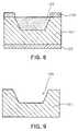
- FIGS. 7 to 14are cross-sectional views illustrating a fabrication process of an LED package according to an embodiment of the invention.
- a metal substrate 101 ′ made of Al or Al-based metalis prepared, and mask patterns 120 and 125 are provided on the metal substrate 101 ′.
- the mask patterns 120 and 125act as a mask in following selective anodization. Describing it in more detail, the mask pattern 120 provided on the top surface of the metal substrate 101 ′ exposes a predetermined area A of the metal substrate 101 ′, and the mask pattern 125 covers the underside of the metal substrate 101 ′.
- the area Acorresponds to a predetermined region of the metal substrate 101 ′ to be formed into a recess which will provide a mounting space for an LED device.
- the mask patterns 120 and 125may be made of for example photoresist or metal such as Ti and Au.
- the metal substrate 101 ′is selectively anodized by the mask patterns 120 and 125 , forming an anodic oxide region 103 ′ as shown in FIG. 8 .
- the anodic oxide region 103 ′is made of Al 2 O 3 that is produced by anodic oxidation of Al.
- the anodic oxide region 103 ′is etched by for example phosphoric acid solution to remove the anodic oxide region 103 ′, as shown in FIG. 9 , thereby producing a package substrate 101 having a recess 103 .
- mask patterns 130 and 135are provided on the package substrate 101 . Describing it in more detail, the mask pattern 135 provided on the underside of the package substrate 101 exposes a predetermined area B of the package substrate 101 , and the mask pattern 130 covers the top surface of the package substrate 101 .
- the mask patterns 130 and 135may be made of photoresist or metal such as Ti and Au like the mask patterns 120 and 125 .
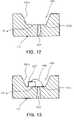
- the package substrate 101is selectively anodized with the mask patterns 130 and 135 , thereby forming an anodic oxide membrane 102 .
- the anodic oxide membrane 102is made of insulator such as Al 2 O 3 , and thus acts to divide the package substrate 101 into two electrodes 101 a and 101 b.
- the mask patterns 130 and 135are completely removed, as shown in FIG. 12 , by for example stripping.
- a reflective metal film of for example Au, Ag, Ti or Alis coated on the side surface of the recess 103 that forms a reflecting surface 101 c .
- the side surface of the recess 103may be Ag plated or Al deposited.
- the bottom of the recess 103may be surface-treated with for example Au, Ag or Al.
- the bottom of the recess 103may be surface-treated by Au or Ag plating or ink jet printing that uses Ag— or Al-containing ink.
- the underside of the package substrate 101is surface-treated by Au or Ag plating.
- the underside of the package substrate 101may be surface-treated simultaneously with the bottom of the recess 103 .
- an LED device 107 of a vertical structureis mounted on the bottom of the recess 103 .
- the LED device 107is die bonded onto the package electrode 101 a at the bottom of the recess 103 , thereby connecting a bottom electrode of the LED device 107 to the electrode 101 a .
- the die bondingmay be carried out by eutectic bonding or by using conductive paste.
- the LED device 107is wire bonded to the package electrode 101 b by a wire 108 . This as a result electrically connects the LED device 107 to the electrodes 101 a and 101 b.
- the LED devicecan be connected to the electrodes for example by wire bonding using a pair of wires or flip-chip bonding (using a pair of solder bumps). That is, as illustrated in FIG. 5 , two wires 108 a and 108 b may be used to connect the electrodes of the vertical structure LED device 107 ′ to the package electrodes 101 a and 101 b , respectively. Then, the LED device 107 ′ may be die bonded to the bottom of the recess 103 by using conductive paste.
- the LED device 107 ′′may be flip-chip bonded to the package electrodes 101 a and 101 b by bumps prepared beforehand.
- an optical element 109such as a glass panel, convex lens and concave lens may be bonded to the top of the package substrate 101 .
- the optical element 109functions as a cover plate sealing the LED device 107 .
- the optical element 109is not essentially required in the invention.
- the metal substrate 101provides a light-reflecting part and a base (i.e., submount).
- the LED packagehas excellent heat radiation characteristics.
- the slot of the prior artis not required any more.
- the package substrate 101is divided into two electrodes 101 a and 101 b by selective anodization using mask patterns instead. Accordingly, the LED package can be fabricated very easily compared to the prior art.
- the recess 103may be formed in an alternative process.
- a package substrate 101 with a recess 103may be formed by injection molding or press molding of metal.
- a recess 103may also be formed by selectively etching a metal substrate.
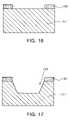
- FIGS. 16 and 17show a process for forming a recess in a metal substrate by selective etching.
- a mask pattern (or etching mask) 140is provided on a metal substrate 101 ′, exposing an area of the metal substrate 101 ′ to be formed into a recess.
- the metal substrate 101 ′is selectively etched by using the mask pattern 140 to form a recess 103 in the metal substrate 101 ′, as shown in FIG. 17 , thereby producing a package substrate 101 with the recess 103 .
- a process steps as illustrated in FIGS. 10 to 14are carried out to produce a desired LED package.
- a number of package substrates 101are produced from a metal plate (or wafer level metal substrate) by forming a number of recesses 103 each having a reflecting surface 101 c therein.
- selective anodizationis performed to form an anodic oxide membrane 102 in each package substrate 101 , thereby dividing the package substrate 101 into package electrodes.
- an LED device 107is mounted on the bottom of each recess 103 .
- This as a resultproduces an LED package array 400 in which a number of LED packages are arrayed and connected together.
- a cover plate or optical elementmay be bonded to the top surface of the package substrates 101 to cover the package array 400 .
- the LED package array 400can be used in for example an illumination system or LCD backlight unit.
- the LED package array 400can also be severed along cutting lines A and B into individual LED packages. This as a result simultaneously produces a number of individual LED packages.
- the LED fabrication process of the inventioncan be used to easily produce an LED package array, in a manner adequate for mass production of LED packages.
- the fabrication process of LED packages of the inventionis adequate for bulk production of a number of LED packages, thereby enabling mass production of high quality LED packages at low cost.
Landscapes
- Engineering & Computer Science (AREA)
- Computer Hardware Design (AREA)
- Microelectronics & Electronic Packaging (AREA)
- Power Engineering (AREA)
- Led Device Packages (AREA)
Abstract
Description
Claims (19)
Applications Claiming Priority (2)
| Application Number | Priority Date | Filing Date | Title |
|---|---|---|---|
| KR1020050036572AKR100593943B1 (en) | 2005-04-30 | 2005-04-30 | Manufacturing method of light emitting diode package |
| KR10-2005-0036572 | 2005-04-30 |
Publications (2)
| Publication Number | Publication Date |
|---|---|
| US20060246617A1 US20060246617A1 (en) | 2006-11-02 |
| US7268014B2true US7268014B2 (en) | 2007-09-11 |
Family
ID=37183318
Family Applications (1)
| Application Number | Title | Priority Date | Filing Date |
|---|---|---|---|
| US11/314,003ActiveUS7268014B2 (en) | 2005-04-30 | 2005-12-22 | Fabrication method of light emitting diode package |
Country Status (4)
| Country | Link |
|---|---|
| US (1) | US7268014B2 (en) |
| JP (1) | JP4331162B2 (en) |
| KR (1) | KR100593943B1 (en) |
| CN (1) | CN100423306C (en) |
Cited By (22)
| Publication number | Priority date | Publication date | Assignee | Title |
|---|---|---|---|---|
| US20070080360A1 (en)* | 2005-10-06 | 2007-04-12 | Url Mirsky | Microelectronic interconnect substrate and packaging techniques |
| US20070210317A1 (en)* | 2006-03-13 | 2007-09-13 | Industrial Technology Research Institute | High power light emitting device assembly with ESD protection ability and the method of manufacturing the same |
| US20070217221A1 (en)* | 2006-03-17 | 2007-09-20 | Samsung Electro-Mechanics Co., Ltd. | Anodized metal substrate module |
| US20070221928A1 (en)* | 2006-03-14 | 2007-09-27 | Samsung Electro-Mechanics Co., Ltd. | Light emitting diode package |
| US20070246715A1 (en)* | 2006-04-21 | 2007-10-25 | Samsung Electro-Mechanics Co., Ltd. | Light emitting diode package having multi-stepped reflecting surface structure and fabrication method thereof |
| US20080006911A1 (en)* | 2006-07-06 | 2008-01-10 | Matsushita Electric Works, Ltd. | Silver layer formed by electrosilvering substrate material |
| US20080020510A1 (en)* | 2006-07-21 | 2008-01-24 | Bunshi Kuratomi | Fabrication method of semiconductor device |
| US20090032832A1 (en)* | 2007-02-16 | 2009-02-05 | Hung-Yi Lin | Light emitting diode structure |
| US20090289272A1 (en)* | 2008-05-23 | 2009-11-26 | Kim Geun Ho | Light emitting device package |
| US20100133557A1 (en)* | 2007-06-22 | 2010-06-03 | Wavenics Inc. | Metal-based photonic device package module and manufacturing method thereof |
| US20100140639A1 (en)* | 2008-12-08 | 2010-06-10 | Kabushiki Kaisha Toshiba | Optical semiconductor device and method of manufacturing optical semiconductor device |
| US20100187546A1 (en)* | 2006-10-17 | 2010-07-29 | Hiroshi Fushimi | Vertical geometry light emitting diode package aggregate and production method of light emitting device using the same |
| US20110116271A1 (en)* | 2009-11-17 | 2011-05-19 | Shunya Ide | Light emitting device and method for manufacturing the same |
| US8044412B2 (en) | 2006-01-20 | 2011-10-25 | Taiwan Semiconductor Manufacturing Company, Ltd | Package for a light emitting element |
| US20120119370A1 (en)* | 2010-11-11 | 2012-05-17 | Jae-Wook Yoo | Semiconductor package and semiconductor system including the same |
| US20120233856A1 (en)* | 2011-03-15 | 2012-09-20 | Kwan Young Oh | Apparatus for manufacturing light emitting device package and method of manufacturing light emitting device package using the same |
| US20130200405A1 (en)* | 2010-08-20 | 2013-08-08 | Osram Opto Semiconductors Gmbh | Optoelectronic Semiconductor Component |
| US8889440B2 (en) | 2010-10-28 | 2014-11-18 | Tsmc Solid State Lighting Ltd. | Light emitting diode optical emitter with transparent electrical connectors |
| US20140367718A1 (en)* | 2012-03-05 | 2014-12-18 | Seoul Viosys Co., Ltd. | Light-emitting device and method of manufacturing the same |
| US9263658B2 (en) | 2012-03-05 | 2016-02-16 | Seoul Viosys Co., Ltd. | Light-emitting device and method of manufacturing the same |
| US9559276B2 (en) | 2012-12-12 | 2017-01-31 | Point Engineering Co., Ltd. | LED metal substrate package and method of manufacturing same |
| US20170338383A1 (en)* | 2016-05-17 | 2017-11-23 | Point Engineering Co., Ltd. | Method for manufacturing chip-mounting substrate, and chip-mounting substrate |
Families Citing this family (40)
| Publication number | Priority date | Publication date | Assignee | Title |
|---|---|---|---|---|
| KR100629521B1 (en) | 2005-07-29 | 2006-09-28 | 삼성전자주식회사 | LED package and manufacturing method thereof and LED array module using same |
| JP2008060204A (en)* | 2006-08-30 | 2008-03-13 | Nec Lcd Technologies Ltd | LED backlight unit and liquid crystal display device using the same |
| CN100438111C (en)* | 2007-01-11 | 2008-11-26 | 鹤山丽得电子实业有限公司 | Method for producing light-emitted diode package structure |
| JP2008227232A (en)* | 2007-03-14 | 2008-09-25 | Matsushita Electric Ind Co Ltd | Semiconductor device manufacturing method, semiconductor device, and optical pickup module |
| CN101060153A (en)* | 2007-05-15 | 2007-10-24 | 佛山市国星光电科技有限公司 | A side LED and its manufacture process |
| CN101060152A (en)* | 2007-05-15 | 2007-10-24 | 佛山市国星光电科技有限公司 | A sheet-type LED |
| US8546818B2 (en) | 2007-06-12 | 2013-10-01 | SemiLEDs Optoelectronics Co., Ltd. | Vertical LED with current-guiding structure |
| US7759670B2 (en)* | 2007-06-12 | 2010-07-20 | SemiLEDs Optoelectronics Co., Ltd. | Vertical LED with current guiding structure |
| US8148733B2 (en) | 2007-06-12 | 2012-04-03 | SemiLEDs Optoelectronics Co., Ltd. | Vertical LED with current guiding structure |
| KR101255280B1 (en)* | 2008-02-22 | 2013-04-15 | 엘지디스플레이 주식회사 | Backlight Unit |
| KR100998010B1 (en) | 2008-04-28 | 2010-12-03 | 삼성엘이디 주식회사 | Light emitting device package and its manufacturing method |
| CN101621101A (en)* | 2008-06-30 | 2010-01-06 | 展晶科技(深圳)有限公司 | LED and production method thereof |
| KR101007139B1 (en)* | 2009-09-10 | 2011-01-10 | 엘지이노텍 주식회사 | Light emitting device and manufacturing method |
| JP5506313B2 (en)* | 2009-09-30 | 2014-05-28 | スタンレー電気株式会社 | Light emitting diode light source for vehicle headlight |
| KR101093719B1 (en) | 2010-01-04 | 2011-12-19 | (주)웨이브닉스이에스피 | Package Module Structure of High Power Device Using Metal Substrate and Manufacturing Method Thereof |
| TW201214804A (en)* | 2010-03-09 | 2012-04-01 | Lg Innotek Co Ltd | Light emitting device package, and display apparatus and lighting system having the same |
| KR101192181B1 (en)* | 2010-03-31 | 2012-10-17 | (주)포인트엔지니어링 | Optical Element Device and Fabricating Method Thereof |
| KR101130688B1 (en) | 2010-05-12 | 2012-04-02 | 한국광기술원 | LED package with radiating structure and Its manufacturing method |
| KR101798232B1 (en)* | 2010-07-07 | 2017-11-15 | 엘지이노텍 주식회사 | Light emitting device, method for fabricating the light emitting device, light emitting device package and lighting system |
| KR101114197B1 (en)* | 2010-08-09 | 2012-02-22 | 엘지이노텍 주식회사 | Light emitting device and lighting system having same |
| CN102044620A (en)* | 2010-11-11 | 2011-05-04 | 深圳市瑞丰光电子股份有限公司 | LED substrate and manufacturing method thereof and LED |
| JP2012109332A (en)* | 2010-11-16 | 2012-06-07 | Showa Denko Kk | Method for manufacturing substrate |
| JP2012134471A (en)* | 2010-11-30 | 2012-07-12 | Fujifilm Corp | Insulating substrate and manufacturing method thereof |
| CN102487112B (en)* | 2010-12-06 | 2015-02-04 | 展晶科技(深圳)有限公司 | Light emitting diode (LED) packaging structure and manufacturing method thereof |
| US9583681B2 (en)* | 2011-02-07 | 2017-02-28 | Cree, Inc. | Light emitter device packages, modules and methods |
| KR101289566B1 (en) | 2011-08-08 | 2013-07-24 | 성균관대학교산학협력단 | Substrates for semiconductor devices, semiconductor devices having the substrates and methods of manufacturing the semiconductor devices |
| KR101284796B1 (en) | 2011-10-05 | 2013-07-10 | (주)포인트엔지니어링 | method for light emitting device with can package and the light emitting device |
| KR101812741B1 (en)* | 2012-03-09 | 2018-01-30 | 서울바이오시스 주식회사 | Light Emitting Diode Package and Method of manufacturing the same |
| KR101306247B1 (en)* | 2012-05-11 | 2013-09-17 | (주)포인트엔지니어링 | Method for light emitting device of back light unit and the light emitting device and array thereof |
| KR101342418B1 (en) | 2012-10-25 | 2013-12-17 | 한국광기술원 | Bidirectional led package |
| KR101403640B1 (en) | 2012-11-20 | 2014-06-05 | 주식회사 세미콘라이트 | Semiconductor light emitting device and method of encapsulating the same |
| CN103904208A (en)* | 2012-12-27 | 2014-07-02 | 宜兴市江旭节能技术有限公司 | Substrate structure |
| US9847462B2 (en) | 2013-10-29 | 2017-12-19 | Point Engineering Co., Ltd. | Array substrate for mounting chip and method for manufacturing the same |
| CN104701446A (en)* | 2013-12-04 | 2015-06-10 | 展晶科技(深圳)有限公司 | Light emitting diode packaging body manufacturing method |
| KR101698918B1 (en)* | 2015-06-19 | 2017-01-23 | (주)포인트엔지니어링 | Substrate comprising slit |
| US9666558B2 (en) | 2015-06-29 | 2017-05-30 | Point Engineering Co., Ltd. | Substrate for mounting a chip and chip package using the substrate |
| KR20170064673A (en)* | 2015-12-02 | 2017-06-12 | (주)포인트엔지니어링 | Chip substrate |
| KR102641336B1 (en) | 2017-09-05 | 2024-02-28 | 쑤저우 레킨 세미컨덕터 컴퍼니 리미티드 | Semiconductor device package |
| WO2021155174A1 (en) | 2020-01-31 | 2021-08-05 | Arizona Board Of Regents On Behalf Of Arizona State University | Urine collection, storage, and testing assembly |
| DE102022114582A1 (en)* | 2022-06-09 | 2023-12-14 | Ams-Osram International Gmbh | OPTOELECTRONIC COMPONENT AND METHOD FOR PRODUCING AN OPTOELECTRONIC COMPONENT |
Citations (5)
| Publication number | Priority date | Publication date | Assignee | Title |
|---|---|---|---|---|
| US6160270A (en)* | 1996-03-27 | 2000-12-12 | Hyundai Electronics America, Inc. | Performance matrix, method of making an active matrix displays incorporating an improved TFT |
| JP2003163378A (en) | 2001-11-26 | 2003-06-06 | Citizen Electronics Co Ltd | Surface mount type light emitting diode and method of manufacturing the same |
| JP2003218398A (en) | 2002-01-18 | 2003-07-31 | Citizen Electronics Co Ltd | Surface mount type light emitting diode and its manufacturing method |
| US20050151142A1 (en)* | 2004-01-08 | 2005-07-14 | Citizen Electronics Co., Ltd. | LED substrate |
| US20060001344A1 (en)* | 2004-01-07 | 2006-01-05 | Kazuaki Ohkubo | Incandescent bulb and incandescent bulb filament |
- 2005
- 2005-04-30KRKR1020050036572Apatent/KR100593943B1/ennot_activeExpired - Fee Related
- 2005-12-22USUS11/314,003patent/US7268014B2/enactiveActive
- 2005-12-27JPJP2005375748Apatent/JP4331162B2/enactiveActive
- 2005-12-30CNCNB2005100971143Apatent/CN100423306C/enactiveActive
Patent Citations (6)
| Publication number | Priority date | Publication date | Assignee | Title |
|---|---|---|---|---|
| US6160270A (en)* | 1996-03-27 | 2000-12-12 | Hyundai Electronics America, Inc. | Performance matrix, method of making an active matrix displays incorporating an improved TFT |
| JP2003163378A (en) | 2001-11-26 | 2003-06-06 | Citizen Electronics Co Ltd | Surface mount type light emitting diode and method of manufacturing the same |
| US6822269B2 (en)* | 2001-11-26 | 2004-11-23 | Citizen Electronics Co., Ltd. | Light emitting diode device |
| JP2003218398A (en) | 2002-01-18 | 2003-07-31 | Citizen Electronics Co Ltd | Surface mount type light emitting diode and its manufacturing method |
| US20060001344A1 (en)* | 2004-01-07 | 2006-01-05 | Kazuaki Ohkubo | Incandescent bulb and incandescent bulb filament |
| US20050151142A1 (en)* | 2004-01-08 | 2005-07-14 | Citizen Electronics Co., Ltd. | LED substrate |
Cited By (49)
| Publication number | Priority date | Publication date | Assignee | Title |
|---|---|---|---|---|
| US20070080360A1 (en)* | 2005-10-06 | 2007-04-12 | Url Mirsky | Microelectronic interconnect substrate and packaging techniques |
| US8044412B2 (en) | 2006-01-20 | 2011-10-25 | Taiwan Semiconductor Manufacturing Company, Ltd | Package for a light emitting element |
| US8552460B2 (en) | 2006-01-20 | 2013-10-08 | Tsmc Solid State Lighting Ltd. | Package for a light emitting element |
| US20070210317A1 (en)* | 2006-03-13 | 2007-09-13 | Industrial Technology Research Institute | High power light emitting device assembly with ESD protection ability and the method of manufacturing the same |
| US7683396B2 (en)* | 2006-03-13 | 2010-03-23 | Industrial Technology Research Institute | High power light emitting device assembly utilizing ESD protective means sandwiched between dual sub-mounts |
| US20090053840A1 (en)* | 2006-03-13 | 2009-02-26 | Ming-Chieh Chou | High power light emitting device assembly with esd protection ability and the method of manufacturing the same |
| US7566912B2 (en)* | 2006-03-14 | 2009-07-28 | Samsung Electro-Mechanics Co., Ltd. | Light emitting diode package |
| US20070221928A1 (en)* | 2006-03-14 | 2007-09-27 | Samsung Electro-Mechanics Co., Ltd. | Light emitting diode package |
| US20070217221A1 (en)* | 2006-03-17 | 2007-09-20 | Samsung Electro-Mechanics Co., Ltd. | Anodized metal substrate module |
| US8058781B2 (en)* | 2006-03-17 | 2011-11-15 | Samsung Electro-Mechanics Co., Ltd. | Anodized metal substrate module |
| US8586128B2 (en) | 2006-04-21 | 2013-11-19 | Samsung Electronics Co., Ltd. | Light emitting diode package having multi-stepped reflecting surface structure and fabrication method thereof |
| US20090227050A1 (en)* | 2006-04-21 | 2009-09-10 | Samsung Electro-Mechanics Co., Ltd. | Light emitting diode package having multi-stepped reflecting surface structure and fabrication method thereof |
| US7547923B2 (en)* | 2006-04-21 | 2009-06-16 | Samsung Electro-Mechanics Co., Ltd. | Light emitting diode package having multi-stepped reflecting surface structure and fabrication method thereof |
| US20070246715A1 (en)* | 2006-04-21 | 2007-10-25 | Samsung Electro-Mechanics Co., Ltd. | Light emitting diode package having multi-stepped reflecting surface structure and fabrication method thereof |
| US8062765B2 (en) | 2006-07-06 | 2011-11-22 | Panasonic Electric Works, Ltd. | Silver layer formed by electrosilvering substrate material |
| US20080006911A1 (en)* | 2006-07-06 | 2008-01-10 | Matsushita Electric Works, Ltd. | Silver layer formed by electrosilvering substrate material |
| US20080020510A1 (en)* | 2006-07-21 | 2008-01-24 | Bunshi Kuratomi | Fabrication method of semiconductor device |
| US20100187546A1 (en)* | 2006-10-17 | 2010-07-29 | Hiroshi Fushimi | Vertical geometry light emitting diode package aggregate and production method of light emitting device using the same |
| US8088635B2 (en)* | 2006-10-17 | 2012-01-03 | C.I. Kasei Company, Limited | Vertical geometry light emitting diode package aggregate and production method of light emitting device using the same |
| US20090032832A1 (en)* | 2007-02-16 | 2009-02-05 | Hung-Yi Lin | Light emitting diode structure |
| US7821094B2 (en)* | 2007-02-16 | 2010-10-26 | Touch Micro-System Technology Inc. | Light emitting diode structure |
| US20100133557A1 (en)* | 2007-06-22 | 2010-06-03 | Wavenics Inc. | Metal-based photonic device package module and manufacturing method thereof |
| US8120045B2 (en)* | 2007-06-22 | 2012-02-21 | Wavenics Inc. | Metal-based photonic device package module |
| US20090289272A1 (en)* | 2008-05-23 | 2009-11-26 | Kim Geun Ho | Light emitting device package |
| US8592855B2 (en) | 2008-05-23 | 2013-11-26 | Lg Innotek Co., Ltd. | Light emitting device package including a substrate having at least two recessed surfaces |
| US7982237B2 (en)* | 2008-05-23 | 2011-07-19 | Lg Innotek Co., Ltd. | Light emitting device package including a semiconductor substrate having at least one surface |
| US8125000B2 (en) | 2008-05-23 | 2012-02-28 | Lg Innotek Co., Ltd. | Light emitting device package having dual recessed substrate |
| US9455375B2 (en) | 2008-05-23 | 2016-09-27 | Lg Innotek Co., Ltd. | Light emitting device package including a substrate having at least two recessed surfaces |
| US8878229B2 (en) | 2008-05-23 | 2014-11-04 | Lg Innotek Co., Ltd. | Light emitting device package including a substrate having at least two recessed surfaces |
| US9190450B2 (en) | 2008-05-23 | 2015-11-17 | Lg Innotek Co., Ltd. | Light emitting device package including a substrate having at least two recessed surfaces |
| US8039857B2 (en) | 2008-12-08 | 2011-10-18 | Kabushiki Kaisha Toshiba | Optical semiconductor device and method of manufacturing optical semiconductor device |
| US20100140639A1 (en)* | 2008-12-08 | 2010-06-10 | Kabushiki Kaisha Toshiba | Optical semiconductor device and method of manufacturing optical semiconductor device |
| US8241937B2 (en) | 2008-12-08 | 2012-08-14 | Kabushiki Kaisha Toshiba | Optical semiconductor device and method of manufacturing optical semiconductor device |
| US20110116271A1 (en)* | 2009-11-17 | 2011-05-19 | Shunya Ide | Light emitting device and method for manufacturing the same |
| US8746932B2 (en)* | 2009-11-17 | 2014-06-10 | Stanley Electric Co., Ltd. | Light emitting device and method for manufacturing the same |
| US20130200405A1 (en)* | 2010-08-20 | 2013-08-08 | Osram Opto Semiconductors Gmbh | Optoelectronic Semiconductor Component |
| US8907369B2 (en)* | 2010-08-20 | 2014-12-09 | Osram Opto Semiconductors Gmbh | Optoelectronic semiconductor component |
| US8889440B2 (en) | 2010-10-28 | 2014-11-18 | Tsmc Solid State Lighting Ltd. | Light emitting diode optical emitter with transparent electrical connectors |
| US8466558B2 (en)* | 2010-11-11 | 2013-06-18 | Samsung Electronics Co., Ltd. | Semiconductor package and semiconductor system including the same |
| US20120119370A1 (en)* | 2010-11-11 | 2012-05-17 | Jae-Wook Yoo | Semiconductor package and semiconductor system including the same |
| US20120233856A1 (en)* | 2011-03-15 | 2012-09-20 | Kwan Young Oh | Apparatus for manufacturing light emitting device package and method of manufacturing light emitting device package using the same |
| US20140367718A1 (en)* | 2012-03-05 | 2014-12-18 | Seoul Viosys Co., Ltd. | Light-emitting device and method of manufacturing the same |
| US9240524B2 (en)* | 2012-03-05 | 2016-01-19 | Seoul Viosys Co., Ltd. | Light-emitting device and method of manufacturing the same |
| US9263658B2 (en) | 2012-03-05 | 2016-02-16 | Seoul Viosys Co., Ltd. | Light-emitting device and method of manufacturing the same |
| US9768362B2 (en) | 2012-03-05 | 2017-09-19 | Seoul Viosys Co., Ltd. | Light-emitting device and method of manufacturing the same |
| US10158050B2 (en) | 2012-03-05 | 2018-12-18 | Seoul Viosys Co., Ltd. | Light-emitting device and method of manufacturing the same |
| US9559276B2 (en) | 2012-12-12 | 2017-01-31 | Point Engineering Co., Ltd. | LED metal substrate package and method of manufacturing same |
| US9768369B2 (en) | 2012-12-12 | 2017-09-19 | Point Engineering Co., Ltd. | LED metal substrate package and method of manufacturing same |
| US20170338383A1 (en)* | 2016-05-17 | 2017-11-23 | Point Engineering Co., Ltd. | Method for manufacturing chip-mounting substrate, and chip-mounting substrate |
Also Published As
| Publication number | Publication date |
|---|---|
| CN1855561A (en) | 2006-11-01 |
| JP4331162B2 (en) | 2009-09-16 |
| JP2006310753A (en) | 2006-11-09 |
| KR100593943B1 (en) | 2006-06-30 |
| US20060246617A1 (en) | 2006-11-02 |
| CN100423306C (en) | 2008-10-01 |
Similar Documents
| Publication | Publication Date | Title |
|---|---|---|
| US7268014B2 (en) | Fabrication method of light emitting diode package | |
| US8394675B2 (en) | Manufacturing light emitting diode (LED) packages | |
| US8202745B2 (en) | Submounts for semiconductor light emitting devices and methods of forming packaged light emitting devices including dispensed encapsulants | |
| KR100637476B1 (en) | Side light emitting diode and method of manufacturing the same | |
| US6995510B2 (en) | Light-emitting unit and method for producing same as well as lead frame used for producing light-emitting unit | |
| US7655957B2 (en) | Submounts for semiconductor light emitting device packages and semiconductor light emitting device packages including the same | |
| US7566912B2 (en) | Light emitting diode package | |
| JP4174823B2 (en) | Semiconductor light emitting device | |
| TWI528508B (en) | High-power light-emitting diode ceramic package manufacturing method | |
| US8835952B2 (en) | Submounts for semiconductor light emitting devices and methods of forming packaged light emitting devices including dispensed encapsulants | |
| US20060001055A1 (en) | Led and fabrication method of same | |
| US20050199884A1 (en) | High power LED package | |
| US20080128724A1 (en) | Light Emitting Device and Process for Manufacturing the Same | |
| JP2011205147A (en) | Method of fabricating led package | |
| WO2013168802A1 (en) | Led module | |
| JP2008042158A (en) | SML type light emitting diode lamp element and manufacturing method thereof | |
| JP5097372B2 (en) | High-current, high-efficiency surface-mount light-emitting diode lamp and method for manufacturing the same | |
| US10312285B2 (en) | LED illuminator and method of making the same | |
| KR100667504B1 (en) | Package of light emitting device and manufacturing method thereof | |
| US11329205B2 (en) | Light emitting device package | |
| KR101911939B1 (en) | Light emitting device | |
| KR20130025455A (en) | Light emitting device package | |
| US20230197886A1 (en) | Semiconductor apparatus | |
| JP2006351611A (en) | Substrate for mounting light-emitting device and optical semiconductor device using same | |
| KR100737822B1 (en) | Light Emitting Diode Package with Lead Frame with High Gloss Plating Layer |
Legal Events
| Date | Code | Title | Description |
|---|---|---|---|
| AS | Assignment | Owner name:SAMSUNG ELECTRO-MECHANICS CO., LTD., KOREA, REPUBL Free format text:ASSIGNMENT OF ASSIGNORS INTEREST;ASSIGNORS:LEE, YOUNG KI;CHOI, SEOG MOON;KIM, YONG SIK;AND OTHERS;REEL/FRAME:017367/0079 Effective date:20051216 | |
| STCF | Information on status: patent grant | Free format text:PATENTED CASE | |
| FEPP | Fee payment procedure | Free format text:PAYOR NUMBER ASSIGNED (ORIGINAL EVENT CODE: ASPN); ENTITY STATUS OF PATENT OWNER: LARGE ENTITY | |
| FEPP | Fee payment procedure | Free format text:PAYER NUMBER DE-ASSIGNED (ORIGINAL EVENT CODE: RMPN); ENTITY STATUS OF PATENT OWNER: LARGE ENTITY | |
| FEPP | Fee payment procedure | Free format text:PAYOR NUMBER ASSIGNED (ORIGINAL EVENT CODE: ASPN); ENTITY STATUS OF PATENT OWNER: LARGE ENTITY | |
| AS | Assignment | Owner name:SAMSUNG LED CO., LTD., KOREA, REPUBLIC OF Free format text:ASSIGNMENT OF ASSIGNORS INTEREST;ASSIGNOR:SAMSUNG ELECTRO-MECHANICS CO., LTD.;REEL/FRAME:024723/0532 Effective date:20100712 | |
| FPAY | Fee payment | Year of fee payment:4 | |
| AS | Assignment | Owner name:SAMSUNG ELECTRONICS CO., LTD., KOREA, REPUBLIC OF Free format text:MERGER;ASSIGNOR:SAMSUNG LED CO., LTD.;REEL/FRAME:028744/0272 Effective date:20120403 | |
| FPAY | Fee payment | Year of fee payment:8 | |
| MAFP | Maintenance fee payment | Free format text:PAYMENT OF MAINTENANCE FEE, 12TH YEAR, LARGE ENTITY (ORIGINAL EVENT CODE: M1553); ENTITY STATUS OF PATENT OWNER: LARGE ENTITY Year of fee payment:12 |