US7267751B2 - Programmable multiplexed active biologic array - Google Patents
Programmable multiplexed active biologic arrayDownload PDFInfo
- Publication number
- US7267751B2 US7267751B2US10/224,750US22475002AUS7267751B2US 7267751 B2US7267751 B2US 7267751B2US 22475002 AUS22475002 AUS 22475002AUS 7267751 B2US7267751 B2US 7267751B2
- Authority
- US
- United States
- Prior art keywords
- voltage
- coupled
- electrode
- chip
- array
- Prior art date
- Legal status (The legal status is an assumption and is not a legal conclusion. Google has not performed a legal analysis and makes no representation as to the accuracy of the status listed.)
- Expired - Lifetime
Links
Images


Classifications
- G—PHYSICS
- G01—MEASURING; TESTING
- G01N—INVESTIGATING OR ANALYSING MATERIALS BY DETERMINING THEIR CHEMICAL OR PHYSICAL PROPERTIES
- G01N27/00—Investigating or analysing materials by the use of electric, electrochemical, or magnetic means
- G01N27/26—Investigating or analysing materials by the use of electric, electrochemical, or magnetic means by investigating electrochemical variables; by using electrolysis or electrophoresis
- G01N27/28—Electrolytic cell components
- G01N27/30—Electrodes, e.g. test electrodes; Half-cells
- G01N27/327—Biochemical electrodes, e.g. electrical or mechanical details for in vitro measurements
- G01N27/3275—Sensing specific biomolecules, e.g. nucleic acid strands, based on an electrode surface reaction
- G01N27/3276—Sensing specific biomolecules, e.g. nucleic acid strands, based on an electrode surface reaction being a hybridisation with immobilised receptors
- G—PHYSICS
- G01—MEASURING; TESTING
- G01N—INVESTIGATING OR ANALYSING MATERIALS BY DETERMINING THEIR CHEMICAL OR PHYSICAL PROPERTIES
- G01N33/00—Investigating or analysing materials by specific methods not covered by groups G01N1/00 - G01N31/00
- G01N33/48—Biological material, e.g. blood, urine; Haemocytometers
- G—PHYSICS
- G01—MEASURING; TESTING
- G01N—INVESTIGATING OR ANALYSING MATERIALS BY DETERMINING THEIR CHEMICAL OR PHYSICAL PROPERTIES
- G01N15/00—Investigating characteristics of particles; Investigating permeability, pore-volume or surface-area of porous materials
- G01N15/06—Investigating concentration of particle suspensions
- B—PERFORMING OPERATIONS; TRANSPORTING
- B01—PHYSICAL OR CHEMICAL PROCESSES OR APPARATUS IN GENERAL
- B01J—CHEMICAL OR PHYSICAL PROCESSES, e.g. CATALYSIS OR COLLOID CHEMISTRY; THEIR RELEVANT APPARATUS
- B01J2219/00—Chemical, physical or physico-chemical processes in general; Their relevant apparatus
- B01J2219/00274—Sequential or parallel reactions; Apparatus and devices for combinatorial chemistry or for making arrays; Chemical library technology
- B01J2219/00583—Features relative to the processes being carried out
- B01J2219/00603—Making arrays on substantially continuous surfaces
- B01J2219/00605—Making arrays on substantially continuous surfaces the compounds being directly bound or immobilised to solid supports
- B—PERFORMING OPERATIONS; TRANSPORTING
- B01—PHYSICAL OR CHEMICAL PROCESSES OR APPARATUS IN GENERAL
- B01J—CHEMICAL OR PHYSICAL PROCESSES, e.g. CATALYSIS OR COLLOID CHEMISTRY; THEIR RELEVANT APPARATUS
- B01J2219/00—Chemical, physical or physico-chemical processes in general; Their relevant apparatus
- B01J2219/00274—Sequential or parallel reactions; Apparatus and devices for combinatorial chemistry or for making arrays; Chemical library technology
- B01J2219/00583—Features relative to the processes being carried out
- B01J2219/00603—Making arrays on substantially continuous surfaces
- B01J2219/00653—Making arrays on substantially continuous surfaces the compounds being bound to electrodes embedded in or on the solid supports
- B—PERFORMING OPERATIONS; TRANSPORTING
- B01—PHYSICAL OR CHEMICAL PROCESSES OR APPARATUS IN GENERAL
- B01J—CHEMICAL OR PHYSICAL PROCESSES, e.g. CATALYSIS OR COLLOID CHEMISTRY; THEIR RELEVANT APPARATUS
- B01J2219/00—Chemical, physical or physico-chemical processes in general; Their relevant apparatus
- B01J2219/00274—Sequential or parallel reactions; Apparatus and devices for combinatorial chemistry or for making arrays; Chemical library technology
- B01J2219/0068—Means for controlling the apparatus of the process
- B01J2219/00698—Measurement and control of process parameters
- B—PERFORMING OPERATIONS; TRANSPORTING
- B01—PHYSICAL OR CHEMICAL PROCESSES OR APPARATUS IN GENERAL
- B01J—CHEMICAL OR PHYSICAL PROCESSES, e.g. CATALYSIS OR COLLOID CHEMISTRY; THEIR RELEVANT APPARATUS
- B01J2219/00—Chemical, physical or physico-chemical processes in general; Their relevant apparatus
- B01J2219/00274—Sequential or parallel reactions; Apparatus and devices for combinatorial chemistry or for making arrays; Chemical library technology
- B01J2219/0068—Means for controlling the apparatus of the process
- B01J2219/00702—Processes involving means for analysing and characterising the products
- B01J2219/00704—Processes involving means for analysing and characterising the products integrated with the reactor apparatus
- G—PHYSICS
- G01—MEASURING; TESTING
- G01N—INVESTIGATING OR ANALYSING MATERIALS BY DETERMINING THEIR CHEMICAL OR PHYSICAL PROPERTIES
- G01N27/00—Investigating or analysing materials by the use of electric, electrochemical, or magnetic means
- G01N27/02—Investigating or analysing materials by the use of electric, electrochemical, or magnetic means by investigating impedance
- G01N27/028—Circuits therefor
- Y—GENERAL TAGGING OF NEW TECHNOLOGICAL DEVELOPMENTS; GENERAL TAGGING OF CROSS-SECTIONAL TECHNOLOGIES SPANNING OVER SEVERAL SECTIONS OF THE IPC; TECHNICAL SUBJECTS COVERED BY FORMER USPC CROSS-REFERENCE ART COLLECTIONS [XRACs] AND DIGESTS
- Y10—TECHNICAL SUBJECTS COVERED BY FORMER USPC
- Y10T—TECHNICAL SUBJECTS COVERED BY FORMER US CLASSIFICATION
- Y10T436/00—Chemistry: analytical and immunological testing
- Y10T436/11—Automated chemical analysis
Definitions
- the field of the inventionrelates generally to devices and methods for carrying out and/or monitoring biologic reactions in the presence of electrical stimuli. More specifically, the present invention relates to the design, implementation, and use of an array-based electronic system for carrying out and/or monitoring biologic reactions in response to electrical stimuli.
- a typical prior art biosensor 1may include a biospecific immobilization surface 2 having an immobilized affinity ligand 3 bound thereto, a transducer 4 capable of sensing the occurrence of chemical reactions which may occur between the immobilized ligand 3 and a specific analyte, and an amplification and control unit 5 for filtering, amplifying and translating signals generated by the transducer 4 into various measurements useful for monitoring the progress or occurrence of a selected biologic reaction.
- Biosensors of the type described aboveare discussed in some detail in Protein Immobilization, Fundamentals & Applications, R. F. Taylor, ed. (1991) (chapter 8); and Immobilized Affinity Ligand Techniques, Hermanson et al. (1992) (chapter 5).
- the fabrication of an array of biosensorsis disclosed, for example, in U.S. patent application Ser. No. 07/872,582, entitled “Optical and Electrical Methods and Apparatus for Molecule Detection” (published Nov. 14, 1993 as International Publication No. W093/22678, and hereinafter referred to as “the Hollis et al. application”).
- the Hollis et al. applicationis directed primarily to biosensory devices comprising an array of test sites which may be electronically addressed using a plurality of conductive leads.
- Various types of biosensorsare described for use at the test sites, and it is suggested that the test sites may be formed in a semiconductor wafer using photolithographic processing techniques. It is further suggested that the test sites may be coupled to associated detection circuitry via transistor switches using row and column addressing techniques employed, for example, in addressing dynamic random access memory (DRAM) or active matrix liquid crystal display (AMLCD) devices.
- DRAMdynamic random access memory
- AMLCDactive matrix liquid crystal display
- these devicesIn addition to the biosensor devices described above, several devices capable of delivering an electrical stimulus (or signal) to a selected location (or test site) within a solution or elsewhere, have been developed. As shown in FIG. 2 , these devices often include a source 6 , such as a current, voltage or power source, an electrode 7 coupled to the current source 6 , a permeation layer 8 formed on one surface of the electrode 7 , and a biologic attachment layer 9 formed upon the permeation layer 8 .
- the permeation layer 8provides for free transport of small counter-ions between the electrode 7 and a solution (not shown), and the attachment layer 9 provides for coupling of specific binding entities.
- micro-locationsmay be fabricated using microlithographic or micromachining techniques, and preferably include a matrix of addressable micro-locations on a surface thereof. Further, individual micro-locations are configured to electronically control and direct the transport and attachment of specific binding entities (e.g., nucleic acids, antibodies, etc.) to itself.
- specific binding entitiese.g., nucleic acids, antibodies, etc.
- the disclosed deviceshave the ability to actively carry out controlled multi-step and multiplex reactions in microscopic formats. Applicable reactions include, for example, nucleic acid hybridizations, antibody/antigen reactions, clinical diagnostics, and multi-step combinational biopolymer synthesis reactions.
- a digitally programmable array-based electronic chipis employed for carrying out biological reactions in response to electrical stimuli.
- the chipincludes an array of electrode sites. Each electrode site includes a sample-and-hold circuit coupled to a working electrode.
- the chipfurther includes a plurality of switches for selectively coupling the working electrodes to the output of a digital-to-analog converter (DAC).
- DACdigital-to-analog converter
- a control logic moduleis coupled to the DAC and the plurality of switches.
- An external processordigitally interfaces with the control logic module, wherein the communication between the control logic module and the external processor includes a clock signal, a data in signal, and a data out signal.
- a methodfor carrying out biological reactions in response to electrical stimuli applied to a plurality of electrodes.
- the methodincludes the step of providing a chip having an array of electrode sites, each electrode site containing a sample-and-hold circuit coupled to a working electrode, a digital-to-analog converter (DAC), a plurality of switches for selectively coupling the DAC to the sample-and-hold circuits, and a control logic module coupled to the DAC and the plurality of switches.
- DACdigital-to-analog converter
- the methodfurther includes the steps of providing an external processor that digitally interfaces with the chip and driving the working electrodes in accordance with the instructions contained in the external processor.
- the chipincludes a digital interface that allows the chip to be controlled by an external processor such as, for example, a personal computer. Individual electrodes or groups of electrodes within the array can be precisely controlled using the external processor. The electrodes can be driven in a number of ways, including constant voltage, constant current, and voltage offset.
- the chipalso includes measurement circuitry to monitor certain aspects of the chip such as, for example, electrode voltages, electrode currents, and temperature conditions of the chip.
- FIG. 1is an illustration of a prior art passive biologic system.
- FIG. 2is an illustration of a prior art active biologic system.
- FIG. 3is an illustration of an array-based circuit in accordance with a preferred embodiment of the present invention.
- FIG. 4is an illustration of an array of electrode sites in accordance with a preferred embodiment of the present invention.
- FIG. 5( a )is an illustration of an electrode site configured to operate in normal mode in accordance with a preferred embodiment of the present invention.
- FIG. 5( b )is an illustration of an electrode site configured to operate in high-impedance mode in accordance with a preferred embodiment of the present invention.
- FIG. 5( c )is an illustration of an electrode site configured to operate in current measurement mode in accordance with an embodiment of the present invention.
- FIG. 5( d )is an illustration of an electrode site configured to operate in voltage measurement mode in accordance with an embodiment of the present invention.
- FIG. 5( e )is an illustration of an electrode site configured to operate in current measurement mode in accordance with a preferred embodiment of the present invention.
- FIG. 5( f )is an illustration of an electrode site configured to operate in voltage measurement mode in accordance with a preferred embodiment of the present invention.
- FIG. 6is an illustration of a die layout of an array-based circuit in accordance with a preferred embodiment of the present invention.
- FIG. 7( a )is an illustration of a frontal view of a cartridge in accordance with a preferred embodiment of the present invention.
- FIG. 7( b )is an illustration of a back view of a cartridge in accordance with a preferred embodiment of the present invention.
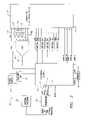
- an array-based electronic chip 10 for carrying out and/or monitoring biologic reactionsin accordance with one preferred form of the present invention comprises an array 20 of active biologic electrode sites 100 . Coupled to the array 20 are a digital-to-analog converter (DAC) 30 , an analog-to-digital converter (ADC) 40 , and a plurality of switch controls, A, B, C, D, E, G, M, L, N, and H.
- DACdigital-to-analog converter
- ADCanalog-to-digital converter
- the array-based chip 10further includes a counter 65 , e.g., a modulo 402 counter, a dual port random access memory module (RAM) 80 , and an electrically eraseable programmable read only memory module (EEPROM) 90 coupled to a control logic module 50 , which, in turn, is coupled to the DAC 30 , the ADC 40 , and switch controls (A-E, G, M, L, N, and H).
- a counter 65e.g., a modulo 402 counter, a dual port random access memory module (RAM) 80 , and an electrically eraseable programmable read only memory module (EEPROM) 90 coupled to a control logic module 50 , which, in turn, is coupled to the DAC 30 , the ADC 40 , and switch controls (A-E, G, M, L, N, and H).
- each of the above listed elementsmay be disposed on a single semiconductor chip, and the entire chip 10 may be fabricated using conventional CMOS semiconductor fabrication techniques. Further details on the fabrication techniques,
- an external processor 62such as a computer, may be used to interface with the chip 10 .
- the external processor 62may communicate with the chip 10 serially, using a transceiver 60 that enables synchronous communication with the control logic module 50 .
- the communication interface between the transceiver 60 and the control logic module 50includes three signals: data-in 52 , data-out 53 , and a clock signal 51 , which may come from the external processor 62 .
- the array 20includes an array of individual biologic electrode sites 100 .
- Each electrode site 100includes a working electrode W coupled with a sample-and-hold circuit 102 , which may include five switches, A(n), B(n), C(n), D(n), and E(n) (n identifies a particular electrode site 100 ) a capacitor 70 , and an operational amplifier 80 .
- the switch controls A, B, C, D, and E shown in FIG. 3may be respectively coupled with each of switches A(n), B(n), C(n), D(n), an E(n) via row and column signal lines coupled to row and column decoders (not shown) to enable the switches to be controlled individually.
- array 20is further coupled with a measurement circuit 137 comprising an external resistor 130 and two nodes coupled with two voltage sense amplifiers 135 for voltage measurements, V 1 and V 2 .
- the array 20may further include two dump circuits 95 , 115 , namely a short dump circuit 95 and a long dump circuit 115 .
- the short dump circuit 95preferably includes switches A(short), G, and M, a capacitor 90 , an operational amplifier 140 , and a short dump electrode D s .
- the long dump circuit 115may include switches A(long), L, and N, a capacitor 110 , an operational amplifier 150 , and a long dump electrode D 1 .
- the short 95 and/or long dump circuits 115may further be coupled with a reference electrode R, via a switch H (reference electrode R is shown in FIG. 3 only coupled to the long dump circuit 115 ).
- An external reference voltage source, V refis preferably applied to the reference electrode R, which may also be coupled to a voltage sense amplifier 135 that provides a voltage measurement node, V 3 .
- Switches G, M, L, N, and Hmay be controlled by the control logic module 50 shown in FIG. 3 .
- the array 20also preferably includes a temperature sensor 139 , which provides a temperature measurement T of the solution containing biologic material.
- each electrode site 100 and dump circuit 95 , 115operates in two states, a sample state and a hold state.
- switch A(n, short, or long)closes, and the voltage, V w , supplied by the DAC 30 is applied to the capacitor 70 , 90 , 110 until the capacitor 70 , 90 , 110 charges to a level that supplies a desired amount of voltage to the operational amplifier 80 , 140 , 150 .
- the electrode site (n) 100 or dump circuit 95 , 115changes to a hold state, where switch A(n, short, or long) opens, and the voltage applied to the noninverting input terminal(+)of the amplifier 80 , 140 , 150 is thus supplied by the capacitor 70 , 90 , 110 .
- the capacitor 70 , 90 , 110is preferably of a size, e.g., approximately 20 pF, that can quickly acquire the desired charge when switch A(n, short, or long) closes and hold the charge for a sufficient amount of time when switch A(n, short, or long) opens.
- the charge in each capacitor 70 , 90 , 110is refreshed, i.e., recharged, preferably once approximately every 40.2 ⁇ sec.
- the electrode sites 100preferably operate in a variety of modes, e.g., normal mode, high-impedance mode, current measurement mode, and voltage measurement mode.
- an electrode site 100is setup to operate in normal mode, wherein a desired voltage is applied to the working electrode W.
- This modeis commonly referred to as “wet” mode because a solution is applied to the surface of the chip 10 containing the working electrodes W.
- Switches B(n) and D(n)form a closed circuit with the working electrode W, i.e., positioned such that the output of the operational amplifier 80 is applied to the working electrode W (i.e., to drive the working electrode W) and then fed back to inverting input terminal ( ⁇ ) of the operational amplifier 80 .
- Switches C(n) and E(n)are open during normal mode.
- the electrode site 100is shown configured in high-impedance mode, which effectively isolates the working electrode W from the array 20 .
- switches B(n) and D(n)form open circuits with the working electrode W, i.e., positioned such that the output of the operational amplifier 80 bypasses the working electrode W.
- Switches C(n) and E(n)are open during high-impedance mode.
- the electrode site 100is configured in current measurement mode, wherein the current through the working electrode W may be measured.
- Switch B(n)forms an open circuit with the working electrode W.
- Switch D(n)forms a closed circuit with the working electrode W.
- Both switches C(n) and E(n)are closed, creating a circuit loop with the measurement circuit 137 , i.e., a circuit loop is created through the external resistor 130 , which is preferably a precision resistor, the working electrode W, and the operational amplifier 80 .
- the current through the working electrode Wmay be calculated by subtracting V 1 from V 2 , the outputs of the voltage sense amplifiers 135 , and dividing the difference by the external resistor 130 in accordance with Ohm's law, i.e., (V 1 -V 2 )/(Resistor 130 ).
- the resistor 130is preferably approximately 385 k ⁇ .
- the electrode site 100is set up in voltage measurement mode, wherein the voltage applied to the working electrode W may be measured and tested.
- the configurationis similar to normal mode shown in FIG. 5( a ), except that switch E(n) is closed.
- the voltage applied at the working electrode Wcan be measured at V 2 .
- this mode of operationalso allows dry test capability, i.e., the electrodes W, D and R may be tested before a solution is placed over the array 20 .
- the integrity of the chip 10can be tested at the manufacturing facility much earlier in the manufacturing process than prior devices.
- the electrode site 100is configured in current measurement mode coupled with an alternative measurement circuit 138 , which includes a transconductance amplifier 200 .
- the noninverting input terminal (+) of the amplifier 200is coupled with switch C(n), which is closed.
- the inverting input terminal ( ⁇ ) and the output of the amplifier 200are coupled with switch E(n), which is also closed.
- the amplifier 200outputs a current, I w , which represents the current through the working electrode W.
- I wmay include parasitic noise caused by the sample-and-hold circuits of the electrode sites 100 .
- the impedance of the amplifier 200is high, which, as can be appreciated by one of ordinary skill in the art, allows the output current to be accurately copied with reduced parasitic noise.
- the amplifier 200produces a copied version I out , I out is passed through a resistor 205 , which may be coupled with a ground or an external voltage source, e.g., a voltage source V ref of 2.5V.
- the current I wmay be calculated by subtracting V 1 by the voltage source, e.g., a V ref of 2.5V, and dividing the difference by the value of the resistor 205 .
- the resistor 205is preferably approximately 385 k ⁇ .
- an electrode site 100is shown coupled with measurement circuit 138 .
- the electrode site 100is configured in voltage measurement mode, wherein the voltage of the working electrode W may be measured.
- the configurationis similar to the configuration of the normal mode, as shown in FIG. 5( a ), except that switch E(n) is closed, thus closing the circuit with the node at V 2 .
- the voltage at V 2represents the voltage of the working electrode W.
- the array 20may include dump circuits 95 , 115 , such as the short dump circuit 95 and long dump circuit 115 shown in FIG. 4 .
- dump circuits 95 , 115such as the short dump circuit 95 and long dump circuit 115 shown in FIG. 4 .
- the sample-and-hold circuits of the electrode sites 100there are some situations where it may be desirable to have a reference node shorted to ground. In other situations, it may be desirable to maintain a reference node at a voltage level other than ground. In these other situations, one approach is to couple the reference node to a dump circuit having a potential other than ground.
- the voltage V 1may switch between a first and second value. If the resistor 205 was coupled to a reference node that was shorted to ground, then the measured current, i.e., V 1 divided by the resistor 205 , may oscillate between a higher current and a lower current. If the reference mode was set to a voltage approximately in between the first and second value, then the measured voltage V 1 of the electrode may switch between a negative value and a positive value, which in turn results in a current measurement that switches between a negative value and a positive value.
- a circuitmay be completed by coupling the working electrode W with another working electrode W having a current flowing in the opposite direction, e.g., a negative current.
- the operation of the dump circuits 95 , 115are similar to the electrode sites 100 . If, for example, the use of a short dump circuit 95 is desired, switch A(short) may close so that V w from the DAC 30 may charge capacitor 90 . When charged, the capacitor 90 supplies a voltage to the noninverting input terminal (+) of operational amplifier 140 . The output of the operational amplifier 140 is fed back into the inverting input terminal ( ⁇ ) of the operation amplifier 140 . Additionally, switches G and M may be closed so the voltage output of the operational amplifier 140 may be applied to the dump electrode D s , which may be coupled with the desired electrode site(s) 100 .
- switch A(long)may close so that V w from the DAC 30 may charge capacitor 110 .
- the capacitor 110supplies a voltage to the noninverting input terminal (+) of operational amplifier 150 .
- the output of the operational amplifier 150is fed back into the inverting input terminal ( ⁇ ) of the operational amplifier 150 .
- switches L and Nmay be closed so the voltage output of the operational amplifier 150 may be applied to the dump electrode D 1 , which also may be coupled with the desired electrode site(s) 100 .
- control logic module 50may control the state and the modes of operation of the electrode sites 100 individually. Further, the control logic module 50 may also control the dump circuits 95 , 115 by controlling switches G, M, L, N, and H.
- the constant voltage methodinvolves applying a desired constant voltage to the working electrode W.
- the constant current methodinvolves applying a desired constant current to the working electrode W.
- the voltage reference methodinvolves maintaining a user programmable offset between a working electrode W and a reference voltage source V ref .
- the voltage source V refmay be coupled with the array 20 via a reference electrode R.
- FIG. 4shows V ref coupled with a reference electrode R that is coupled with the long dump circuit 115 via switch H, however V ref may be coupled with the array at other locations, for example, with the short dump circuit 95 .
- the voltage of the reference electrode Rmay be monitored using a sensor amplifier 135 (represented as V 3 in FIG. 4 ).
- the reference electrode Ris located in the flow cell (discussed in more detail below) that is formed in connection with the chip 10 .
- the array-based electronic chip 10may also control the delivery method of the electrical stimuli to each working electrode W and the dump circuits 95 , 115 , individually or in selected groups.
- the chip 10using the DAC 30 , sets voltage V w , which is coupled to the electrode sites 100 and the dump circuits.
- the DAC 30retrieves the desired V w value from the dual port RAM 80 and the control logic module 50 .
- the RAM 80may have 402 bytes of data. Each byte corresponds to an electrode site 100 or a dump circuit 95 , 115 and represents a specific voltage for V w .
- the chip 10charges each electrode site 100 and dump circuit 95 , 115 sequentially, controlled by the counter 65 .
- the counter 65specifies the byte (n) within the RAM 80 that the DAC retrieves to set V w .
- the control logic 50reads the module counter 65 and sets the corresponding electrode site 100 or dump circuit 95 , 115 into the sample state, i.e., the control logic module 50 closes switch A(n) for the corresponding electrode site (n) 100 or dump circuit 95 , 115 .
- the control logic module 50changes the electrode site (n) 100 or dump circuit 95 , 115 to a hold state, i.e., opens switch A(n).
- the module counter 65increments to the next byte within the RAM 80 , i.e., (n+1), and the DAC 30 reads the voltage value in the next byte (n+1) to set V w . While the DAC 30 is retrieving the voltage value of byte (n+1) and setting V w , the control logic 50 reads the counter 65 and sets the next electrode site (n+1) 100 or dump circuit 95 , 115 into the sample state, i.e., the control logic module 50 closes switch A(n+1). When capacitor 70 , 90 , 110 charges, then the control logic module 50 opens switch A(n+1).
- This processis known as “refreshing” the electrodes, and the process cycles through the sample-and-hold circuits 102 and dump circuits 95 , 115 sequentially during operation.
- Timingis critical because the refreshing process must be fast enough to maintain the desired charges on the capacitors, 70 , 90 , 110 , before they deplete to undesirable levels, but each circuit must maintain a sample state long enough for the respective capacitor, 70 , 90 , 110 , to charge to the desired level.
- Using a dual port RAM 80allows the counter 65 and the DAC 30 to access the RAM 80 simultaneously, which improves the timing of the chip 10 .
- the DAC 30 and the counter 65are driven by a clock signal of approximately 10 MHz.
- the desired voltageis applied via V w , as described above.
- the desired voltagemay be either a single voltage value or a programmed series of different voltage values, such as positive and negative voltages values.
- the control logic module 50may set the electrode site 100 of the particular working electrode W to voltage measurement mode. Thus, the voltage of the working electrode V 2 may be monitored. The measurement at V 2 may be fed into the ADC 40 to convert the measurement into a digital value. The control logic module 50 may then retrieve the working electrode W voltage V 2 from the ADC 40 to compare with the desired constant voltage. If V 2 is too high or too low, then the control logic module 50 may accordingly adjust the value for V w set in the RAM 80 for the corresponding electrode site 100 .
- the desired voltage Vwis applied to produce the desired constant current through the working electrode W, as described above.
- the desired constant currentmay be either a single value or a programmed series of different current values, such as positive and negative current values.
- the control logic module 50sets the corresponding electrode site 100 to current measurement mode and then monitors the current by retrieving data, such as V 1 and/or V 2 , from the ADC 40 and calculating the current, as described above. If the current is too high or too low, the control logic 50 may accordingly adjust the V w .
- the desired V wis applied such that the voltage at the working electrode W is offset from V ref by a user programmable amount.
- the programmed offsetmay be either a single value or a series of different values, such as positive and negative values.
- the control logic module 50sets the particular electrode site 100 to dry voltage test mode and then compares V 2 with V 3 , the voltage of the reference electrode R that is coupled with V ref . If the offset is too much or too little, the control logic module 50 may accordingly adjust V w , as described above.
- the control logic module 50also includes a reset signal, which, when invoked, refreshes the electrodes sites 100 and the dump circuits 95 , 115 starting from the first electrode site 100 , i.e., the counter 65 is reset to 0.
- control logic module 50may monitor the temperature of the array 20 via the temperature sensor module 139 .
- the chip 10further includes an EEPROM 90 coupled with the control logic module 50 .
- the EEPROM 90is read/write, but the data may be changed by “powering up” the EEPROM 90 only. This may be achieved by applying approximately 20V to V pp and performing a write.
- the interfaceis a three wire serial interface which includes data-in 52 , data-out 53 , and clock 51 , as shown in FIG. 3 .
- data-in 52 and data-out 53are separate, the interface is half duplex, i.e., a response coming from the chip 10 occurs only after a command from the external processor 62 has been fully received.
- the interfaceis synchronously driven by the clock 51 , preferably at 10 MHz. Preferably, there is a two clock cycle delay between data-in 52 and data-out 53 .
- the data-in 52 signalis a 24-bit message which includes: a start bit, a 12-bit address, a 1-bit command, an 8 bit data field, and two stop bits.
- the 12-bit addressmay represent, for example, the individual switches controls, A, B, C, D, E, G, M, L, N, H, the DAC 30 controls, the data to be written to either the EEPROM 90 or the RAM 80 , e.g., voltage values for V w when the DAC 30 refreshes the electrode sites 100 , the ADC 40 controls, temperature sensor 139 controls.
- the 1-bit commandmay indicate whether the external processor 62 intends to read data from the chip 10 or write data to the chip 10 , e.g., write to the RAM 80 or EEPROM 90 or control the switches.
- the data-out signalis an 11-bit message produced by the control logic module 50 if the 1-bit command in data-in is a read command.
- the data-out signalincludes: a start bit, an 8-bit data field, and two stop bits.
- the 8-bit data fieldmay include, for example, the status of the switches, i.e., whether the switch is open or closed and/or data from the RAM 80 , EEPROM 90 , and/or ADC 40 , which may include data from V 1 , V 2 , V 3 , V ref , and/or T.
- FIG. 6a preferred die 300 layout of an embodiment of the present invention is shown.
- the die 300is preferably approximately 8 mm by 5 mm.
- 400 working electrodes W of the array 20are shown in a matrix of 16 rows and 25 columns.
- an embodiment of the present inventionmay include any number of working electrodes W.
- the electrodes Ware preferably approximately 50 microns in diameter on 150 micron centers.
- the working electrodes Ware preferably comprised of platinum or platinum silicide and are preferably planar.
- the long dump electrodes D 1 and the short dump electrodes D sare also shown along the perimeter of the working electrodes W.
- bond pads 305for chip related functions.
- the reference electrode Ris not shown.
- the reference electrodeis comprised of silver, and thus resides off the die 300 , preferably in the flow cell 230 .
- the reference electrode Rmay be coupled to the array 20 via the bond pads.
- the remaining elements of the chip 10reside within the die 300 .
- the chip 10may be designed such that there is less than 10% electrode current variation from 630 nm light incident at 10 mw/mm 2 .
- An optical block(not shown) may be placed in the top of the metallization layer of the electrodes W to help resolve this issue.
- the die 300is shown installed in a cartridge 225 used to apply a solution to the working electrodes W and more readily couple the chip 10 with an external processor 62 .
- the cartridge 225includes a flow cell 230 that acts as a chamber over the die 300 that contains the solution containing charged biological material.
- Injection ports 220are placed on both sides of the die 300 . The solution enters one port 220 , flows over the working electrodes W, and exits the other port 220 .
- the cartridge 225further includes pins within the die 300 to electrically connect certain elements within the array-based chip 10 to external components.
- the V pp pinis for coupling a power supply of approximately 20V with the EEPROM 90 .
- the D Vdd pinis for coupling the array-based chip 10 with a digital power supply of approximately 5V
- the A Vdd pinis for coupling the chip 10 with an analog power supply of approximately 5V.
- the Reset pinis for coupling a reset signal to the control logic module 50 .
- the data-out 53 , data-in 52 , and clock 51 pinsare for interfacing with the external processor 62 , which may be via a transceiver 60 .
- the R 1 and R 2 pinsare for coupling each end of an external resistor, e.g., resistor 130 , to the array 20 .
- the A Vss pinis for coupling the array 20 with an analog ground, and the D Vss is for coupling the array 20 with a digital ground.
- a chip-is-in-use pinprovides a signal that indicates whether the chip 10 is in operation.
Landscapes
- Health & Medical Sciences (AREA)
- Life Sciences & Earth Sciences (AREA)
- Chemical & Material Sciences (AREA)
- Physics & Mathematics (AREA)
- Molecular Biology (AREA)
- Immunology (AREA)
- Pathology (AREA)
- Analytical Chemistry (AREA)
- Biochemistry (AREA)
- General Health & Medical Sciences (AREA)
- General Physics & Mathematics (AREA)
- Electrochemistry (AREA)
- Chemical Kinetics & Catalysis (AREA)
- Spectroscopy & Molecular Physics (AREA)
- Engineering & Computer Science (AREA)
- Medicinal Chemistry (AREA)
- Hematology (AREA)
- Dispersion Chemistry (AREA)
- Food Science & Technology (AREA)
- Biomedical Technology (AREA)
- Urology & Nephrology (AREA)
- Investigating Or Analyzing Materials By The Use Of Electric Means (AREA)
Abstract
Description
Claims (22)
Priority Applications (8)
| Application Number | Priority Date | Filing Date | Title |
|---|---|---|---|
| US10/224,750US7267751B2 (en) | 2002-08-20 | 2002-08-20 | Programmable multiplexed active biologic array |
| AU2003263885AAU2003263885A1 (en) | 2002-08-20 | 2003-08-07 | Programmable multiplexed active biologic array |
| CA002495426ACA2495426A1 (en) | 2002-08-20 | 2003-08-07 | Programmable multiplexed active biologic array |
| PCT/US2003/025807WO2004018991A2 (en) | 2002-08-20 | 2003-08-07 | Programmable multiplexed active biologic array |
| EP03793099AEP1540307A2 (en) | 2002-08-20 | 2003-08-07 | Programmable multiplexed active biologic array |
| JP2004531048AJP2005536746A (en) | 2002-08-20 | 2003-08-07 | Programmable multiple active biological arrays |
| KR1020057002759AKR20050042481A (en) | 2002-08-20 | 2003-08-07 | Programmable multiplexed active biologic array |
| US11/852,826US7943023B2 (en) | 2002-08-20 | 2007-09-10 | Programmable multiplexed active biologic array |
Applications Claiming Priority (1)
| Application Number | Priority Date | Filing Date | Title |
|---|---|---|---|
| US10/224,750US7267751B2 (en) | 2002-08-20 | 2002-08-20 | Programmable multiplexed active biologic array |
Related Child Applications (1)
| Application Number | Title | Priority Date | Filing Date |
|---|---|---|---|
| US11/852,826ContinuationUS7943023B2 (en) | 2002-08-20 | 2007-09-10 | Programmable multiplexed active biologic array |
Publications (2)
| Publication Number | Publication Date |
|---|---|
| US20040038420A1 US20040038420A1 (en) | 2004-02-26 |
| US7267751B2true US7267751B2 (en) | 2007-09-11 |
Family
ID=31886863
Family Applications (2)
| Application Number | Title | Priority Date | Filing Date |
|---|---|---|---|
| US10/224,750Expired - LifetimeUS7267751B2 (en) | 2002-08-20 | 2002-08-20 | Programmable multiplexed active biologic array |
| US11/852,826Expired - Fee RelatedUS7943023B2 (en) | 2002-08-20 | 2007-09-10 | Programmable multiplexed active biologic array |
Family Applications After (1)
| Application Number | Title | Priority Date | Filing Date |
|---|---|---|---|
| US11/852,826Expired - Fee RelatedUS7943023B2 (en) | 2002-08-20 | 2007-09-10 | Programmable multiplexed active biologic array |
Country Status (7)
| Country | Link |
|---|---|
| US (2) | US7267751B2 (en) |
| EP (1) | EP1540307A2 (en) |
| JP (1) | JP2005536746A (en) |
| KR (1) | KR20050042481A (en) |
| AU (1) | AU2003263885A1 (en) |
| CA (1) | CA2495426A1 (en) |
| WO (1) | WO2004018991A2 (en) |
Cited By (41)
| Publication number | Priority date | Publication date | Assignee | Title |
|---|---|---|---|---|
| US7598768B1 (en)* | 2005-08-05 | 2009-10-06 | Xilinx, Inc. | Method and apparatus for dynamic port provisioning within a programmable logic device |
| US20090255801A1 (en)* | 2008-04-11 | 2009-10-15 | Haas Alfred M | Programmable Electrode Arrays and Methods for Manipulating and Sensing Cells and Substances Using Same |
| US7858034B2 (en) | 1993-11-01 | 2010-12-28 | Gamida For Life B.V. | Circuits for the control of output current in an electronic device for performing active biological operations |
| US7857957B2 (en) | 1994-07-07 | 2010-12-28 | Gamida For Life B.V. | Integrated portable biological detection system |
| US8115635B2 (en) | 2005-02-08 | 2012-02-14 | Abbott Diabetes Care Inc. | RF tag on test strips, test strip vials and boxes |
| US8552771B1 (en) | 2012-05-29 | 2013-10-08 | Life Technologies Corporation | System for reducing noise in a chemical sensor array |
| US8692298B2 (en) | 2006-12-14 | 2014-04-08 | Life Technologies Corporation | Chemical sensor array having multiple sensors per well |
| US8731847B2 (en) | 2010-06-30 | 2014-05-20 | Life Technologies Corporation | Array configuration and readout scheme |
| US8742472B2 (en) | 2006-12-14 | 2014-06-03 | Life Technologies Corporation | Chemically sensitive sensors with sample and hold capacitors |
| US8841217B1 (en) | 2013-03-13 | 2014-09-23 | Life Technologies Corporation | Chemical sensor with protruded sensor surface |
| US8912005B1 (en) | 2010-09-24 | 2014-12-16 | Life Technologies Corporation | Method and system for delta double sampling |
| US8912580B2 (en) | 2009-05-29 | 2014-12-16 | Life Technologies Corporation | Active chemically-sensitive sensors with in-sensor current sources |
| US8963216B2 (en) | 2013-03-13 | 2015-02-24 | Life Technologies Corporation | Chemical sensor with sidewall spacer sensor surface |
| US8962366B2 (en) | 2013-01-28 | 2015-02-24 | Life Technologies Corporation | Self-aligned well structures for low-noise chemical sensors |
| US9116117B2 (en) | 2013-03-15 | 2015-08-25 | Life Technologies Corporation | Chemical sensor with sidewall sensor surface |
| US9128044B2 (en) | 2013-03-15 | 2015-09-08 | Life Technologies Corporation | Chemical sensors with consistent sensor surface areas |
| US9194000B2 (en) | 2008-06-25 | 2015-11-24 | Life Technologies Corporation | Methods and apparatus for measuring analytes using large scale FET arrays |
| US9239313B2 (en) | 2010-06-30 | 2016-01-19 | Life Technologies Corporation | Ion-sensing charge-accumulation circuits and methods |
| US9279801B2 (en) | 2013-07-26 | 2016-03-08 | Axion Biosystems, Inc. | Devices, systems and methods for high-throughput electrophysiology |
| US9290756B2 (en) | 2008-11-10 | 2016-03-22 | The Board Of Trustees Of The University Of Illinois | Apparatus and methods for high throughput network electrophysiology and cellular analysis |
| US9404920B2 (en) | 2006-12-14 | 2016-08-02 | Life Technologies Corporation | Methods and apparatus for detecting molecular interactions using FET arrays |
| US9618475B2 (en) | 2010-09-15 | 2017-04-11 | Life Technologies Corporation | Methods and apparatus for measuring analytes |
| US9671363B2 (en) | 2013-03-15 | 2017-06-06 | Life Technologies Corporation | Chemical sensor with consistent sensor surface areas |
| US9823217B2 (en) | 2013-03-15 | 2017-11-21 | Life Technologies Corporation | Chemical device with thin conductive element |
| US9835585B2 (en) | 2013-03-15 | 2017-12-05 | Life Technologies Corporation | Chemical sensor with protruded sensor surface |
| US9841398B2 (en) | 2013-01-08 | 2017-12-12 | Life Technologies Corporation | Methods for manufacturing well structures for low-noise chemical sensors |
| US9852919B2 (en) | 2013-01-04 | 2017-12-26 | Life Technologies Corporation | Methods and systems for point of use removal of sacrificial material |
| US9927393B2 (en) | 2009-05-29 | 2018-03-27 | Life Technologies Corporation | Methods and apparatus for measuring analytes |
| US9944981B2 (en) | 2008-10-22 | 2018-04-17 | Life Technologies Corporation | Methods and apparatus for measuring analytes |
| US9960253B2 (en) | 2010-07-03 | 2018-05-01 | Life Technologies Corporation | Chemically sensitive sensor with lightly doped drains |
| US9970984B2 (en) | 2011-12-01 | 2018-05-15 | Life Technologies Corporation | Method and apparatus for identifying defects in a chemical sensor array |
| US10067117B2 (en) | 2014-08-12 | 2018-09-04 | Axion Biosystems, Inc. | Cell-based biosensor array and associated methods for manufacturing the same |
| US10077472B2 (en) | 2014-12-18 | 2018-09-18 | Life Technologies Corporation | High data rate integrated circuit with power management |
| US10100357B2 (en) | 2013-05-09 | 2018-10-16 | Life Technologies Corporation | Windowed sequencing |
| US10379079B2 (en) | 2014-12-18 | 2019-08-13 | Life Technologies Corporation | Methods and apparatus for measuring analytes using large scale FET arrays |
| US10451585B2 (en) | 2009-05-29 | 2019-10-22 | Life Technologies Corporation | Methods and apparatus for measuring analytes |
| US10458942B2 (en) | 2013-06-10 | 2019-10-29 | Life Technologies Corporation | Chemical sensor array having multiple sensors per well |
| US10605767B2 (en) | 2014-12-18 | 2020-03-31 | Life Technologies Corporation | High data rate integrated circuit with transmitter configuration |
| US11231451B2 (en) | 2010-06-30 | 2022-01-25 | Life Technologies Corporation | Methods and apparatus for testing ISFET arrays |
| US11307166B2 (en) | 2010-07-01 | 2022-04-19 | Life Technologies Corporation | Column ADC |
| US11339430B2 (en) | 2007-07-10 | 2022-05-24 | Life Technologies Corporation | Methods and apparatus for measuring analytes using large scale FET arrays |
Families Citing this family (23)
| Publication number | Priority date | Publication date | Assignee | Title |
|---|---|---|---|---|
| EP1735668A2 (en)* | 2004-04-13 | 2006-12-27 | President And Fellows Of Harvard College | Methods and apparatus for manipulation and/or detection of biological samples and other objects |
| DE102004020829B4 (en)* | 2004-04-28 | 2006-05-18 | Fraunhofer-Gesellschaft zur Förderung der angewandten Forschung e.V. | Sensor for the detection of ingredients of liquids, in particular biological materials, and detection device containing this sensor |
| US8536661B1 (en) | 2004-06-25 | 2013-09-17 | University Of Hawaii | Biosensor chip sensor protection methods |
| WO2007008246A2 (en) | 2004-11-12 | 2007-01-18 | The Board Of Trustees Of The Leland Stanford Junior University | Charge perturbation detection system for dna and other molecules |
| JP4797498B2 (en)* | 2005-08-03 | 2011-10-19 | 凸版印刷株式会社 | Hybridization detection method |
| US11001881B2 (en) | 2006-08-24 | 2021-05-11 | California Institute Of Technology | Methods for detecting analytes |
| US11525156B2 (en) | 2006-07-28 | 2022-12-13 | California Institute Of Technology | Multiplex Q-PCR arrays |
| US8048626B2 (en) | 2006-07-28 | 2011-11-01 | California Institute Of Technology | Multiplex Q-PCR arrays |
| US20100276734A1 (en)* | 2006-08-14 | 2010-11-04 | Georgia Tech Research Corporation | Electrochemical biosensor arrays and systems and methods of making same |
| US11560588B2 (en) | 2006-08-24 | 2023-01-24 | California Institute Of Technology | Multiplex Q-PCR arrays |
| US20080248900A1 (en)* | 2007-04-05 | 2008-10-09 | Gus Hernandez | Practice baseball swing machine |
| WO2009031088A1 (en)* | 2007-09-06 | 2009-03-12 | Koninklijke Philips Electronics N.V. | Method and apparatus for chemical analysis of fluids |
| US8673627B2 (en) | 2009-05-29 | 2014-03-18 | Life Technologies Corporation | Apparatus and methods for performing electrochemical reactions |
| US20110022331A1 (en)* | 2009-07-27 | 2011-01-27 | Meso Scale Technologies, Llc | Assay Information Management Methods and Devices |
| US8821798B2 (en) | 2012-01-19 | 2014-09-02 | Life Technologies Corporation | Titanium nitride as sensing layer for microwell structure |
| US8747748B2 (en) | 2012-01-19 | 2014-06-10 | Life Technologies Corporation | Chemical sensor with conductive cup-shaped sensor surface |
| US9983163B2 (en)* | 2013-04-30 | 2018-05-29 | Board Of Regents, The University Of Texas System | Integrated electro-analytical biosensor array |
| KR101508158B1 (en)* | 2013-07-08 | 2015-04-07 | 한국과학기술연구원 | Control of electrical offset volage in Functional Electrical Stimulation system |
| US9708647B2 (en) | 2015-03-23 | 2017-07-18 | Insilixa, Inc. | Multiplexed analysis of nucleic acid hybridization thermodynamics using integrated arrays |
| US9499861B1 (en) | 2015-09-10 | 2016-11-22 | Insilixa, Inc. | Methods and systems for multiplex quantitative nucleic acid amplification |
| WO2017155858A1 (en) | 2016-03-07 | 2017-09-14 | Insilixa, Inc. | Nucleic acid sequence identification using solid-phase cyclic single base extension |
| JP7687957B2 (en) | 2019-03-14 | 2025-06-03 | インシリクサ, インコーポレイテッド | Methods and systems for time-gated fluorescence-based detection |
| WO2021216955A1 (en) | 2020-04-24 | 2021-10-28 | The Trustees Of The University Of Pennsylvania | Digital fluid teleportation, advanced biological virtualization, and large scale integration of organ-on-chips and microphysiological models |
Citations (41)
| Publication number | Priority date | Publication date | Assignee | Title |
|---|---|---|---|---|
| US3430072A (en) | 1966-01-11 | 1969-02-25 | Us Navy | Sample and hold circuit |
| US3957592A (en) | 1974-07-29 | 1976-05-18 | Owens-Illinois, Inc. | Measurement of polarographic current |
| US4594135A (en) | 1985-02-20 | 1986-06-10 | Ionics Incorporated | Process and apparatus for electrically desorbing components selectively sorbed on granules |
| US4661224A (en) | 1984-11-26 | 1987-04-28 | Ionics, Incorporated | Process and apparatus for electrically desorbing components selectively sorbed on an electrolytically conducting barrier |
| US4772851A (en) | 1986-01-28 | 1988-09-20 | Her Majesty The Queen In Right Of Canada, As Represented By The Minister Of National Defence | General purpose potentiostatic test system using a multiplexer for test electrode selection |
| US4787963A (en) | 1987-05-04 | 1988-11-29 | Syntro Corporation | Method and means for annealing complementary nucleic acid molecules at an accelerated rate |
| US4924224A (en) | 1987-10-09 | 1990-05-08 | Hitachi, Ltd. | High-accuracy A/D converter |
| EP0376611A2 (en) | 1988-12-30 | 1990-07-04 | The Board Of Trustees Of The Leland Stanford Junior University | Electrophoretic system |
| US5074977A (en) | 1987-05-05 | 1991-12-24 | The Washington Technology Center | Digital biosensors and method of using same |
| US5164319A (en) | 1985-08-22 | 1992-11-17 | Molecular Devices Corporation | Multiple chemically modulated capacitance determination |
| US5178161A (en) | 1988-09-02 | 1993-01-12 | The Board Of Trustees Of The Leland Stanford Junior University | Microelectronic interface |
| US5187096A (en) | 1991-08-08 | 1993-02-16 | Rensselaer Polytechnic Institute | Cell substrate electrical impedance sensor with multiple electrode array |
| US5234566A (en) | 1988-08-18 | 1993-08-10 | Australian Membrane And Biotechnology Research Institute Ltd. | Sensitivity and selectivity of ion channel biosensor membranes |
| WO1993022678A2 (en) | 1992-04-23 | 1993-11-11 | Massachusetts Institute Of Technology | Optical and electrical methods and apparatus for molecule detection |
| US5378343A (en) | 1993-01-11 | 1995-01-03 | Tufts University | Electrode assembly including iridium based mercury ultramicroelectrode array |
| WO1995012808A1 (en) | 1993-11-01 | 1995-05-11 | Nanogen, Inc. | Self-addressable self-assembling microelectronic systems and devices for molecular biological analysis and diagnostics |
| US5434049A (en) | 1992-02-28 | 1995-07-18 | Hitachi, Ltd. | Separation of polynucleotides using supports having a plurality of electrode-containing cells |
| US5445934A (en) | 1989-06-07 | 1995-08-29 | Affymax Technologies N.V. | Array of oligonucleotides on a solid substrate |
| US5491097A (en) | 1989-06-15 | 1996-02-13 | Biocircuits Corporation | Analyte detection with multilayered bioelectronic conductivity sensors |
| US5527670A (en) | 1990-09-12 | 1996-06-18 | Scientific Generics Limited | Electrochemical denaturation of double-stranded nucleic acid |
| US5632957A (en) | 1993-11-01 | 1997-05-27 | Nanogen | Molecular biological diagnostic systems including electrodes |
| US5632876A (en) | 1995-06-06 | 1997-05-27 | David Sarnoff Research Center, Inc. | Apparatus and methods for controlling fluid flow in microchannels |
| US5770721A (en) | 1993-08-11 | 1998-06-23 | University Of Chicago | Method of manufacturing a matrix for the detection of mismatches |
| US5849486A (en) | 1993-11-01 | 1998-12-15 | Nanogen, Inc. | Methods for hybridization analysis utilizing electrically controlled hybridization |
| US5851772A (en) | 1996-01-29 | 1998-12-22 | University Of Chicago | Microchip method for the enrichment of specific DNA sequences |
| US5861247A (en) | 1996-01-26 | 1999-01-19 | University Of Chicago | Rapid method to detect duplex formation in sequencing by hybridization methods |
| US5891630A (en) | 1991-11-19 | 1999-04-06 | Houston Advanced Res Center | Multi-site detection apparatus |
| US5905024A (en) | 1996-12-17 | 1999-05-18 | University Of Chicago | Method for performing site-specific affinity fractionation for use in DNA sequencing |
| US5965452A (en) | 1996-07-09 | 1999-10-12 | Nanogen, Inc. | Multiplexed active biologic array |
| US5981268A (en)* | 1997-05-30 | 1999-11-09 | Board Of Trustees, Leland Stanford, Jr. University | Hybrid biosensors |
| WO1999067019A1 (en) | 1998-06-24 | 1999-12-29 | Therasense, Inc. | Combinatorial electrochemical syntheses |
| US6017696A (en) | 1993-11-01 | 2000-01-25 | Nanogen, Inc. | Methods for electronic stringency control for molecular biological analysis and diagnostics |
| US6048690A (en) | 1991-11-07 | 2000-04-11 | Nanogen, Inc. | Methods for electronic fluorescent perturbation for analysis and electronic perturbation catalysis for synthesis |
| US6051380A (en) | 1993-11-01 | 2000-04-18 | Nanogen, Inc. | Methods and procedures for molecular biological analysis and diagnostics |
| US6054270A (en) | 1988-05-03 | 2000-04-25 | Oxford Gene Technology Limited | Analying polynucleotide sequences |
| US6068818A (en) | 1993-11-01 | 2000-05-30 | Nanogen, Inc. | Multicomponent devices for molecular biological analysis and diagnostics |
| US6093302A (en) | 1998-01-05 | 2000-07-25 | Combimatrix Corporation | Electrochemical solid phase synthesis |
| US6099803A (en) | 1994-07-07 | 2000-08-08 | Nanogen, Inc. | Advanced active electronic devices for molecular biological analysis and diagnostics |
| US20010036641A1 (en) | 1998-06-18 | 2001-11-01 | Gordon Gary B. | Methods and devices for carrying out chemical reactions |
| US6602400B1 (en)* | 2000-06-15 | 2003-08-05 | Motorola, Inc. | Method for enhanced bio-conjugation events |
| US6726820B1 (en)* | 2001-09-19 | 2004-04-27 | Applera Corporation | Method of separating biomolecule-containing samples with a microdevice with integrated memory |
- 2002
- 2002-08-20USUS10/224,750patent/US7267751B2/ennot_activeExpired - Lifetime
- 2003
- 2003-08-07KRKR1020057002759Apatent/KR20050042481A/ennot_activeWithdrawn
- 2003-08-07CACA002495426Apatent/CA2495426A1/ennot_activeAbandoned
- 2003-08-07EPEP03793099Apatent/EP1540307A2/ennot_activeWithdrawn
- 2003-08-07WOPCT/US2003/025807patent/WO2004018991A2/enactiveApplication Filing
- 2003-08-07AUAU2003263885Apatent/AU2003263885A1/ennot_activeAbandoned
- 2003-08-07JPJP2004531048Apatent/JP2005536746A/enactivePending
- 2007
- 2007-09-10USUS11/852,826patent/US7943023B2/ennot_activeExpired - Fee Related
Patent Citations (47)
| Publication number | Priority date | Publication date | Assignee | Title |
|---|---|---|---|---|
| US3430072A (en) | 1966-01-11 | 1969-02-25 | Us Navy | Sample and hold circuit |
| US3957592A (en) | 1974-07-29 | 1976-05-18 | Owens-Illinois, Inc. | Measurement of polarographic current |
| US4661224A (en) | 1984-11-26 | 1987-04-28 | Ionics, Incorporated | Process and apparatus for electrically desorbing components selectively sorbed on an electrolytically conducting barrier |
| US4594135A (en) | 1985-02-20 | 1986-06-10 | Ionics Incorporated | Process and apparatus for electrically desorbing components selectively sorbed on granules |
| US5164319A (en) | 1985-08-22 | 1992-11-17 | Molecular Devices Corporation | Multiple chemically modulated capacitance determination |
| US4772851A (en) | 1986-01-28 | 1988-09-20 | Her Majesty The Queen In Right Of Canada, As Represented By The Minister Of National Defence | General purpose potentiostatic test system using a multiplexer for test electrode selection |
| US4787963A (en) | 1987-05-04 | 1988-11-29 | Syntro Corporation | Method and means for annealing complementary nucleic acid molecules at an accelerated rate |
| US5074977A (en) | 1987-05-05 | 1991-12-24 | The Washington Technology Center | Digital biosensors and method of using same |
| US4924224A (en) | 1987-10-09 | 1990-05-08 | Hitachi, Ltd. | High-accuracy A/D converter |
| US6054270A (en) | 1988-05-03 | 2000-04-25 | Oxford Gene Technology Limited | Analying polynucleotide sequences |
| US5234566A (en) | 1988-08-18 | 1993-08-10 | Australian Membrane And Biotechnology Research Institute Ltd. | Sensitivity and selectivity of ion channel biosensor membranes |
| US5178161A (en) | 1988-09-02 | 1993-01-12 | The Board Of Trustees Of The Leland Stanford Junior University | Microelectronic interface |
| US5314495A (en) | 1988-09-02 | 1994-05-24 | The Board Of Trustees Of The Leland Stanford Junior University | Microelectronic interface |
| EP0376611A2 (en) | 1988-12-30 | 1990-07-04 | The Board Of Trustees Of The Leland Stanford Junior University | Electrophoretic system |
| US5445934A (en) | 1989-06-07 | 1995-08-29 | Affymax Technologies N.V. | Array of oligonucleotides on a solid substrate |
| US5491097A (en) | 1989-06-15 | 1996-02-13 | Biocircuits Corporation | Analyte detection with multilayered bioelectronic conductivity sensors |
| US5527670A (en) | 1990-09-12 | 1996-06-18 | Scientific Generics Limited | Electrochemical denaturation of double-stranded nucleic acid |
| US5187096A (en) | 1991-08-08 | 1993-02-16 | Rensselaer Polytechnic Institute | Cell substrate electrical impedance sensor with multiple electrode array |
| US6048690A (en) | 1991-11-07 | 2000-04-11 | Nanogen, Inc. | Methods for electronic fluorescent perturbation for analysis and electronic perturbation catalysis for synthesis |
| US5891630A (en) | 1991-11-19 | 1999-04-06 | Houston Advanced Res Center | Multi-site detection apparatus |
| US5653939A (en) | 1991-11-19 | 1997-08-05 | Massachusetts Institute Of Technology | Optical and electrical methods and apparatus for molecule detection |
| US5434049A (en) | 1992-02-28 | 1995-07-18 | Hitachi, Ltd. | Separation of polynucleotides using supports having a plurality of electrode-containing cells |
| WO1993022678A2 (en) | 1992-04-23 | 1993-11-11 | Massachusetts Institute Of Technology | Optical and electrical methods and apparatus for molecule detection |
| US5378343A (en) | 1993-01-11 | 1995-01-03 | Tufts University | Electrode assembly including iridium based mercury ultramicroelectrode array |
| US5770721A (en) | 1993-08-11 | 1998-06-23 | University Of Chicago | Method of manufacturing a matrix for the detection of mismatches |
| US5632957A (en) | 1993-11-01 | 1997-05-27 | Nanogen | Molecular biological diagnostic systems including electrodes |
| US6051380A (en) | 1993-11-01 | 2000-04-18 | Nanogen, Inc. | Methods and procedures for molecular biological analysis and diagnostics |
| US5849486A (en) | 1993-11-01 | 1998-12-15 | Nanogen, Inc. | Methods for hybridization analysis utilizing electrically controlled hybridization |
| US6068818A (en) | 1993-11-01 | 2000-05-30 | Nanogen, Inc. | Multicomponent devices for molecular biological analysis and diagnostics |
| WO1995012808A1 (en) | 1993-11-01 | 1995-05-11 | Nanogen, Inc. | Self-addressable self-assembling microelectronic systems and devices for molecular biological analysis and diagnostics |
| US6017696A (en) | 1993-11-01 | 2000-01-25 | Nanogen, Inc. | Methods for electronic stringency control for molecular biological analysis and diagnostics |
| US5605662A (en) | 1993-11-01 | 1997-02-25 | Nanogen, Inc. | Active programmable electronic devices for molecular biological analysis and diagnostics |
| US6099803A (en) | 1994-07-07 | 2000-08-08 | Nanogen, Inc. | Advanced active electronic devices for molecular biological analysis and diagnostics |
| US5632876A (en) | 1995-06-06 | 1997-05-27 | David Sarnoff Research Center, Inc. | Apparatus and methods for controlling fluid flow in microchannels |
| US5861247A (en) | 1996-01-26 | 1999-01-19 | University Of Chicago | Rapid method to detect duplex formation in sequencing by hybridization methods |
| US5851772A (en) | 1996-01-29 | 1998-12-22 | University Of Chicago | Microchip method for the enrichment of specific DNA sequences |
| US5965452A (en) | 1996-07-09 | 1999-10-12 | Nanogen, Inc. | Multiplexed active biologic array |
| US6258606B1 (en)* | 1996-07-09 | 2001-07-10 | Nanogen, Inc. | Multiplexed active biologic array |
| US6682936B2 (en)* | 1996-07-09 | 2004-01-27 | Nanogen, Inc. | Addressable biologic electrode array |
| US5905024A (en) | 1996-12-17 | 1999-05-18 | University Of Chicago | Method for performing site-specific affinity fractionation for use in DNA sequencing |
| US5981268A (en)* | 1997-05-30 | 1999-11-09 | Board Of Trustees, Leland Stanford, Jr. University | Hybrid biosensors |
| US6093302A (en) | 1998-01-05 | 2000-07-25 | Combimatrix Corporation | Electrochemical solid phase synthesis |
| US20010036641A1 (en) | 1998-06-18 | 2001-11-01 | Gordon Gary B. | Methods and devices for carrying out chemical reactions |
| WO1999067019A1 (en) | 1998-06-24 | 1999-12-29 | Therasense, Inc. | Combinatorial electrochemical syntheses |
| US20020008038A1 (en) | 1998-06-24 | 2002-01-24 | Therasense, Inc. | Combinatorial Electrochemical Synthesis |
| US6602400B1 (en)* | 2000-06-15 | 2003-08-05 | Motorola, Inc. | Method for enhanced bio-conjugation events |
| US6726820B1 (en)* | 2001-09-19 | 2004-04-27 | Applera Corporation | Method of separating biomolecule-containing samples with a microdevice with integrated memory |
Non-Patent Citations (1)
| Title |
|---|
| Fiaccabrino et al, "Array Of Individually Addressable Microelectrodes", Sensors & Actuators B, 16-19, 1994, 675-677. |
Cited By (101)
| Publication number | Priority date | Publication date | Assignee | Title |
|---|---|---|---|---|
| US7858034B2 (en) | 1993-11-01 | 2010-12-28 | Gamida For Life B.V. | Circuits for the control of output current in an electronic device for performing active biological operations |
| US7857957B2 (en) | 1994-07-07 | 2010-12-28 | Gamida For Life B.V. | Integrated portable biological detection system |
| US8542122B2 (en) | 2005-02-08 | 2013-09-24 | Abbott Diabetes Care Inc. | Glucose measurement device and methods using RFID |
| US8115635B2 (en) | 2005-02-08 | 2012-02-14 | Abbott Diabetes Care Inc. | RF tag on test strips, test strip vials and boxes |
| US8223021B2 (en) | 2005-02-08 | 2012-07-17 | Abbott Diabetes Care Inc. | RF tag on test strips, test strip vials and boxes |
| US8358210B2 (en) | 2005-02-08 | 2013-01-22 | Abbott Diabetes Care Inc. | RF tag on test strips, test strip vials and boxes |
| US8390455B2 (en) | 2005-02-08 | 2013-03-05 | Abbott Diabetes Care Inc. | RF tag on test strips, test strip vials and boxes |
| US7598768B1 (en)* | 2005-08-05 | 2009-10-06 | Xilinx, Inc. | Method and apparatus for dynamic port provisioning within a programmable logic device |
| US9989489B2 (en) | 2006-12-14 | 2018-06-05 | Life Technnologies Corporation | Methods for calibrating an array of chemically-sensitive sensors |
| US10816506B2 (en) | 2006-12-14 | 2020-10-27 | Life Technologies Corporation | Method for measuring analytes using large scale chemfet arrays |
| US8692298B2 (en) | 2006-12-14 | 2014-04-08 | Life Technologies Corporation | Chemical sensor array having multiple sensors per well |
| US10203300B2 (en) | 2006-12-14 | 2019-02-12 | Life Technologies Corporation | Methods and apparatus for measuring analytes using large scale FET arrays |
| US8742472B2 (en) | 2006-12-14 | 2014-06-03 | Life Technologies Corporation | Chemically sensitive sensors with sample and hold capacitors |
| US10633699B2 (en) | 2006-12-14 | 2020-04-28 | Life Technologies Corporation | Methods and apparatus for measuring analytes using large scale FET arrays |
| US9269708B2 (en) | 2006-12-14 | 2016-02-23 | Life Technologies Corporation | Methods and apparatus for measuring analytes using large scale FET arrays |
| US8766328B2 (en) | 2006-12-14 | 2014-07-01 | Life Technologies Corporation | Chemically-sensitive sample and hold sensors |
| US12140560B2 (en) | 2006-12-14 | 2024-11-12 | Life Technologies Corporation | Methods and apparatus for measuring analytes using large scale FET arrays |
| US12066399B2 (en) | 2006-12-14 | 2024-08-20 | Life Technologies Corporation | Methods and apparatus for measuring analytes using large scale FET arrays |
| US8890216B2 (en) | 2006-12-14 | 2014-11-18 | Life Technologies Corporation | Methods and apparatus for measuring analytes using large scale FET arrays |
| US10502708B2 (en) | 2006-12-14 | 2019-12-10 | Life Technologies Corporation | Chemically-sensitive sensor array calibration circuitry |
| US9951382B2 (en) | 2006-12-14 | 2018-04-24 | Life Technologies Corporation | Methods and apparatus for measuring analytes using large scale FET arrays |
| US10415079B2 (en) | 2006-12-14 | 2019-09-17 | Life Technologies Corporation | Methods and apparatus for detecting molecular interactions using FET arrays |
| US11732297B2 (en)* | 2006-12-14 | 2023-08-22 | Life Technologies Corporation | Methods and apparatus for measuring analytes using large scale FET arrays |
| US11435314B2 (en) | 2006-12-14 | 2022-09-06 | Life Technologies Corporation | Chemically-sensitive sensor array device |
| US9023189B2 (en) | 2006-12-14 | 2015-05-05 | Life Technologies Corporation | High density sensor array without wells |
| US9134269B2 (en) | 2006-12-14 | 2015-09-15 | Life Technologies Corporation | Methods and apparatus for measuring analytes using large scale FET arrays |
| US9404920B2 (en) | 2006-12-14 | 2016-08-02 | Life Technologies Corporation | Methods and apparatus for detecting molecular interactions using FET arrays |
| US20220340965A1 (en)* | 2006-12-14 | 2022-10-27 | Life Technologies Corporation | Methods and Apparatus for Measuring Analytes Using Large Scale FET Arrays |
| US11339430B2 (en) | 2007-07-10 | 2022-05-24 | Life Technologies Corporation | Methods and apparatus for measuring analytes using large scale FET arrays |
| US20090255801A1 (en)* | 2008-04-11 | 2009-10-15 | Haas Alfred M | Programmable Electrode Arrays and Methods for Manipulating and Sensing Cells and Substances Using Same |
| US9194000B2 (en) | 2008-06-25 | 2015-11-24 | Life Technologies Corporation | Methods and apparatus for measuring analytes using large scale FET arrays |
| US9944981B2 (en) | 2008-10-22 | 2018-04-17 | Life Technologies Corporation | Methods and apparatus for measuring analytes |
| US11448613B2 (en) | 2008-10-22 | 2022-09-20 | Life Technologies Corporation | ChemFET sensor array including overlying array of wells |
| US12146853B2 (en) | 2008-10-22 | 2024-11-19 | Life Technologies Corporation | Methods and apparatus including array of reaction chambers over array of chemFET sensors for measuring analytes |
| US11137369B2 (en) | 2008-10-22 | 2021-10-05 | Life Technologies Corporation | Integrated sensor arrays for biological and chemical analysis |
| US9964515B2 (en) | 2008-10-22 | 2018-05-08 | Life Technologies Corporation | Integrated sensor arrays for biological and chemical analysis |
| US11874250B2 (en) | 2008-10-22 | 2024-01-16 | Life Technologies Corporation | Integrated sensor arrays for biological and chemical analysis |
| US9290756B2 (en) | 2008-11-10 | 2016-03-22 | The Board Of Trustees Of The University Of Illinois | Apparatus and methods for high throughput network electrophysiology and cellular analysis |
| US8912580B2 (en) | 2009-05-29 | 2014-12-16 | Life Technologies Corporation | Active chemically-sensitive sensors with in-sensor current sources |
| US11768171B2 (en) | 2009-05-29 | 2023-09-26 | Life Technologies Corporation | Methods and apparatus for measuring analytes |
| US10451585B2 (en) | 2009-05-29 | 2019-10-22 | Life Technologies Corporation | Methods and apparatus for measuring analytes |
| US12038405B2 (en) | 2009-05-29 | 2024-07-16 | Life Technologies Corporation | Methods and apparatus for measuring analytes |
| US10718733B2 (en) | 2009-05-29 | 2020-07-21 | Life Technologies Corporation | Methods and apparatus for measuring analytes |
| US10809226B2 (en) | 2009-05-29 | 2020-10-20 | Life Technologies Corporation | Methods and apparatus for measuring analytes |
| US9927393B2 (en) | 2009-05-29 | 2018-03-27 | Life Technologies Corporation | Methods and apparatus for measuring analytes |
| US11692964B2 (en) | 2009-05-29 | 2023-07-04 | Life Technologies Corporation | Methods and apparatus for measuring analytes |
| US10641729B2 (en) | 2010-06-30 | 2020-05-05 | Life Technologies Corporation | Column ADC |
| US8741680B2 (en) | 2010-06-30 | 2014-06-03 | Life Technologies Corporation | Two-transistor pixel array |
| US8983783B2 (en) | 2010-06-30 | 2015-03-17 | Life Technologies Corporation | Chemical detection device having multiple flow channels |
| US10481123B2 (en) | 2010-06-30 | 2019-11-19 | Life Technologies Corporation | Ion-sensing charge-accumulation circuits and methods |
| US12038406B2 (en) | 2010-06-30 | 2024-07-16 | Life Technologies Corporation | Semiconductor-based chemical detection device |
| US9164070B2 (en) | 2010-06-30 | 2015-10-20 | Life Technologies Corporation | Column adc |
| US8731847B2 (en) | 2010-06-30 | 2014-05-20 | Life Technologies Corporation | Array configuration and readout scheme |
| US11231451B2 (en) | 2010-06-30 | 2022-01-25 | Life Technologies Corporation | Methods and apparatus for testing ISFET arrays |
| US8742471B2 (en) | 2010-06-30 | 2014-06-03 | Life Technologies Corporation | Chemical sensor array with leakage compensation circuit |
| US9239313B2 (en) | 2010-06-30 | 2016-01-19 | Life Technologies Corporation | Ion-sensing charge-accumulation circuits and methods |
| US11307166B2 (en) | 2010-07-01 | 2022-04-19 | Life Technologies Corporation | Column ADC |
| US9960253B2 (en) | 2010-07-03 | 2018-05-01 | Life Technologies Corporation | Chemically sensitive sensor with lightly doped drains |
| US12050195B2 (en) | 2010-09-15 | 2024-07-30 | Life Technologies Corporation | Methods and apparatus for measuring analytes using chemfet arrays |
| US9618475B2 (en) | 2010-09-15 | 2017-04-11 | Life Technologies Corporation | Methods and apparatus for measuring analytes |
| US9958414B2 (en) | 2010-09-15 | 2018-05-01 | Life Technologies Corporation | Apparatus for measuring analytes including chemical sensor array |
| US9110015B2 (en) | 2010-09-24 | 2015-08-18 | Life Technologies Corporation | Method and system for delta double sampling |
| US8912005B1 (en) | 2010-09-24 | 2014-12-16 | Life Technologies Corporation | Method and system for delta double sampling |
| US10365321B2 (en) | 2011-12-01 | 2019-07-30 | Life Technologies Corporation | Method and apparatus for identifying defects in a chemical sensor array |
| US9970984B2 (en) | 2011-12-01 | 2018-05-15 | Life Technologies Corporation | Method and apparatus for identifying defects in a chemical sensor array |
| US10598723B2 (en) | 2011-12-01 | 2020-03-24 | Life Technologies Corporation | Method and apparatus for identifying defects in a chemical sensor array |
| US9985624B2 (en) | 2012-05-29 | 2018-05-29 | Life Technologies Corporation | System for reducing noise in a chemical sensor array |
| US9270264B2 (en) | 2012-05-29 | 2016-02-23 | Life Technologies Corporation | System for reducing noise in a chemical sensor array |
| US8786331B2 (en) | 2012-05-29 | 2014-07-22 | Life Technologies Corporation | System for reducing noise in a chemical sensor array |
| US8552771B1 (en) | 2012-05-29 | 2013-10-08 | Life Technologies Corporation | System for reducing noise in a chemical sensor array |
| US10404249B2 (en) | 2012-05-29 | 2019-09-03 | Life Technologies Corporation | System for reducing noise in a chemical sensor array |
| US9852919B2 (en) | 2013-01-04 | 2017-12-26 | Life Technologies Corporation | Methods and systems for point of use removal of sacrificial material |
| US9841398B2 (en) | 2013-01-08 | 2017-12-12 | Life Technologies Corporation | Methods for manufacturing well structures for low-noise chemical sensors |
| US10436742B2 (en) | 2013-01-08 | 2019-10-08 | Life Technologies Corporation | Methods for manufacturing well structures for low-noise chemical sensors |
| US8962366B2 (en) | 2013-01-28 | 2015-02-24 | Life Technologies Corporation | Self-aligned well structures for low-noise chemical sensors |
| US8841217B1 (en) | 2013-03-13 | 2014-09-23 | Life Technologies Corporation | Chemical sensor with protruded sensor surface |
| US8963216B2 (en) | 2013-03-13 | 2015-02-24 | Life Technologies Corporation | Chemical sensor with sidewall spacer sensor surface |
| US9995708B2 (en) | 2013-03-13 | 2018-06-12 | Life Technologies Corporation | Chemical sensor with sidewall spacer sensor surface |
| US10422767B2 (en) | 2013-03-15 | 2019-09-24 | Life Technologies Corporation | Chemical sensor with consistent sensor surface areas |
| US9128044B2 (en) | 2013-03-15 | 2015-09-08 | Life Technologies Corporation | Chemical sensors with consistent sensor surface areas |
| US9671363B2 (en) | 2013-03-15 | 2017-06-06 | Life Technologies Corporation | Chemical sensor with consistent sensor surface areas |
| US9116117B2 (en) | 2013-03-15 | 2015-08-25 | Life Technologies Corporation | Chemical sensor with sidewall sensor surface |
| US10481124B2 (en) | 2013-03-15 | 2019-11-19 | Life Technologies Corporation | Chemical device with thin conductive element |
| US9835585B2 (en) | 2013-03-15 | 2017-12-05 | Life Technologies Corporation | Chemical sensor with protruded sensor surface |
| US9823217B2 (en) | 2013-03-15 | 2017-11-21 | Life Technologies Corporation | Chemical device with thin conductive element |
| US10100357B2 (en) | 2013-05-09 | 2018-10-16 | Life Technologies Corporation | Windowed sequencing |
| US11028438B2 (en) | 2013-05-09 | 2021-06-08 | Life Technologies Corporation | Windowed sequencing |
| US10655175B2 (en) | 2013-05-09 | 2020-05-19 | Life Technologies Corporation | Windowed sequencing |
| US11774401B2 (en) | 2013-06-10 | 2023-10-03 | Life Technologies Corporation | Chemical sensor array having multiple sensors per well |
| US10816504B2 (en) | 2013-06-10 | 2020-10-27 | Life Technologies Corporation | Chemical sensor array having multiple sensors per well |
| US11499938B2 (en) | 2013-06-10 | 2022-11-15 | Life Technologies Corporation | Chemical sensor array having multiple sensors per well |
| US10458942B2 (en) | 2013-06-10 | 2019-10-29 | Life Technologies Corporation | Chemical sensor array having multiple sensors per well |
| US9279801B2 (en) | 2013-07-26 | 2016-03-08 | Axion Biosystems, Inc. | Devices, systems and methods for high-throughput electrophysiology |
| US9329168B2 (en) | 2013-07-26 | 2016-05-03 | Axion Biosystems, Inc. | Devices, systems and methods for high-throughput electrophysiology |
| US10067117B2 (en) | 2014-08-12 | 2018-09-04 | Axion Biosystems, Inc. | Cell-based biosensor array and associated methods for manufacturing the same |
| US11536688B2 (en) | 2014-12-18 | 2022-12-27 | Life Technologies Corporation | High data rate integrated circuit with transmitter configuration |
| US10767224B2 (en) | 2014-12-18 | 2020-09-08 | Life Technologies Corporation | High data rate integrated circuit with power management |
| US10077472B2 (en) | 2014-12-18 | 2018-09-18 | Life Technologies Corporation | High data rate integrated circuit with power management |
| US10605767B2 (en) | 2014-12-18 | 2020-03-31 | Life Technologies Corporation | High data rate integrated circuit with transmitter configuration |
| US10379079B2 (en) | 2014-12-18 | 2019-08-13 | Life Technologies Corporation | Methods and apparatus for measuring analytes using large scale FET arrays |
| US12196704B2 (en) | 2014-12-18 | 2025-01-14 | Life Technologies Corporation | High data rate integrated circuit with transmitter configuration |
Also Published As
| Publication number | Publication date |
|---|---|
| WO2004018991A2 (en) | 2004-03-04 |
| US20040038420A1 (en) | 2004-02-26 |
| EP1540307A2 (en) | 2005-06-15 |
| AU2003263885A1 (en) | 2004-03-11 |
| US7943023B2 (en) | 2011-05-17 |
| WO2004018991A3 (en) | 2004-07-22 |
| US20080110755A1 (en) | 2008-05-15 |
| JP2005536746A (en) | 2005-12-02 |
| KR20050042481A (en) | 2005-05-09 |
| CA2495426A1 (en) | 2004-03-04 |
Similar Documents
| Publication | Publication Date | Title |
|---|---|---|
| US7267751B2 (en) | Programmable multiplexed active biologic array | |
| US5965452A (en) | Multiplexed active biologic array | |
| US8702921B2 (en) | Biosensors array and method for operating a biosensor array | |
| Schienle et al. | A fully electronic DNA sensor with 128 positions and in-pixel A/D conversion | |
| WO1998001758A9 (en) | Multiplexed active biologic array | |
| US6251685B1 (en) | Readout method for molecular biological electronically addressable arrays | |
| US6741490B2 (en) | Sensing method and apparatus for resistance memory device | |
| US7084641B2 (en) | Measuring cell and measuring field comprising measuring cells of this type, use of a measuring and use of a measuring field | |
| Ingebrandt et al. | Label‐free detection of DNA using field‐effect transistors | |
| US6926865B2 (en) | Method and apparatus for detecting DNA hybridization | |
| US8617382B2 (en) | Process and device for emulating a counter-electrode in a monolithically integrated electrochemical analysis system | |
| US20050024953A1 (en) | Double gate transistor arrangement for receiving electrical signals from living cells | |
| US20030152930A1 (en) | Method and apparatus for detecting DNA hybridization | |
| WO2025137204A1 (en) | Microled array with active control | |
| WO2024091986A1 (en) | Electrochemical systems with massively parallel array of controllable electrochemical cells and sensor system for sparse sensing |
Legal Events
| Date | Code | Title | Description |
|---|---|---|---|
| AS | Assignment | Owner name:NANOGEN, INC., CALIFORNIA Free format text:ASSIGNMENT OF ASSIGNORS INTEREST;ASSIGNORS:GELBART, RICHARD;POWRIE, DON L.;SWANSON, PAUL DAVID;REEL/FRAME:013223/0222 Effective date:20020806 | |
| AS | Assignment | Owner name:NANOGEN, INC., CALIFORNIA Free format text:ASSIGNMENT OF ASSIGNORS INTEREST;ASSIGNORS:GELBART, RICHARD;POWRIE, DON L.;SWANSON, PAUL DAVID;REEL/FRAME:013489/0249 Effective date:20021022 | |
| STCF | Information on status: patent grant | Free format text:PATENTED CASE | |
| AS | Assignment | Owner name:PORTSIDE GROWTH & OPPORTUNITY FUND, AS COLLATERAL Free format text:GRANT OF SECURITY INTEREST;ASSIGNOR:NANOGEN, INC.;REEL/FRAME:021291/0605 Effective date:20080327 | |
| FEPP | Fee payment procedure | Free format text:PAYOR NUMBER ASSIGNED (ORIGINAL EVENT CODE: ASPN); ENTITY STATUS OF PATENT OWNER: SMALL ENTITY | |
| AS | Assignment | Owner name:ELITECH HOLDING B.V., NETHERLANDS Free format text:ORDER RELEASING SECURITY AGREEMENTS AND AUTHORIZING ASSIGNMENT;ASSIGNOR:PORTSIDE GROWTH & OPPORTUNITY FUND;REEL/FRAME:025690/0537 Effective date:20090624 | |
| FPAY | Fee payment | Year of fee payment:4 | |
| AS | Assignment | Owner name:GAMIDA FOR LIFE, B.V., NETHERLANDS Free format text:ASSIGNMENT OF ASSIGNORS INTEREST;ASSIGNOR:ELITECH HOLDING B.V.;REEL/FRAME:028260/0154 Effective date:20091208 | |
| FPAY | Fee payment | Year of fee payment:8 | |
| MAFP | Maintenance fee payment | Free format text:PAYMENT OF MAINTENANCE FEE, 12TH YR, SMALL ENTITY (ORIGINAL EVENT CODE: M2553); ENTITY STATUS OF PATENT OWNER: SMALL ENTITY Year of fee payment:12 | |
| AS | Assignment | Owner name:ADOR DIAGNOSTICS S.R.L., ITALY Free format text:ASSIGNMENT OF ASSIGNORS INTEREST;ASSIGNOR:GAMIDA FOR LIFE, B.V.;REEL/FRAME:048749/0393 Effective date:20190331 |