US7267678B2 - Intramedullary implant for fracture fixation - Google Patents
Intramedullary implant for fracture fixationDownload PDFInfo
- Publication number
- US7267678B2 US7267678B2US10/675,864US67586403AUS7267678B2US 7267678 B2US7267678 B2US 7267678B2US 67586403 AUS67586403 AUS 67586403AUS 7267678 B2US7267678 B2US 7267678B2
- Authority
- US
- United States
- Prior art keywords
- bone
- bone fragment
- fragment
- fracture
- implant
- Prior art date
- Legal status (The legal status is an assumption and is not a legal conclusion. Google has not performed a legal analysis and makes no representation as to the accuracy of the status listed.)
- Expired - Fee Related, expires
Links
- 239000007943implantSubstances0.000titleclaimsabstractdescription95
- 210000000988bone and boneAnatomy0.000claimsabstractdescription133
- 239000012634fragmentSubstances0.000claimsabstractdescription120
- 208000010392Bone FracturesDiseases0.000claimsabstractdescription71
- 210000005065subchondral bone plateAnatomy0.000claimsdescription14
- 238000000034methodMethods0.000claimsdescription13
- 238000003780insertionMethods0.000claimsdescription10
- 230000037431insertionEffects0.000claimsdescription10
- 238000004904shorteningMethods0.000claimsdescription9
- 230000006835compressionEffects0.000claimsdescription7
- 238000007906compressionMethods0.000claimsdescription7
- 230000035515penetrationEffects0.000claimsdescription2
- 206010017076FractureDiseases0.000description31
- 210000002435tendonAnatomy0.000description5
- 210000000707wristAnatomy0.000description5
- 238000009434installationMethods0.000description4
- 230000008685targetingEffects0.000description3
- 238000013519translationMethods0.000description3
- 210000000623ulnaAnatomy0.000description3
- 206010037802Radius fractureDiseases0.000description2
- 210000003423ankleAnatomy0.000description2
- 238000006073displacement reactionMethods0.000description2
- 230000000694effectsEffects0.000description2
- 210000002082fibulaAnatomy0.000description2
- 230000035876healingEffects0.000description2
- 230000007794irritationEffects0.000description2
- 210000003041ligamentAnatomy0.000description2
- 238000012986modificationMethods0.000description2
- 230000004048modificationEffects0.000description2
- 210000000466volar plateAnatomy0.000description2
- 208000024779Comminuted FracturesDiseases0.000description1
- 229910001200FerrotitaniumInorganic materials0.000description1
- RTAQQCXQSZGOHL-UHFFFAOYSA-NTitaniumChemical compound[Ti]RTAQQCXQSZGOHL-UHFFFAOYSA-N0.000description1
- 230000002159abnormal effectEffects0.000description1
- 238000013459approachMethods0.000description1
- 230000036770blood supplyEffects0.000description1
- 238000013461designMethods0.000description1
- 230000001627detrimental effectEffects0.000description1
- 230000004064dysfunctionEffects0.000description1
- 210000003414extremityAnatomy0.000description1
- 229910052751metalInorganic materials0.000description1
- 239000002184metalSubstances0.000description1
- 230000000149penetrating effectEffects0.000description1
- 230000001737promoting effectEffects0.000description1
- 210000004872soft tissueAnatomy0.000description1
- 229910001220stainless steelInorganic materials0.000description1
- 239000010935stainless steelSubstances0.000description1
- 230000002739subcortical effectEffects0.000description1
- -1such asSubstances0.000description1
- 230000000153supplemental effectEffects0.000description1
- 239000010936titaniumSubstances0.000description1
Images


Classifications
- A—HUMAN NECESSITIES
- A61—MEDICAL OR VETERINARY SCIENCE; HYGIENE
- A61B—DIAGNOSIS; SURGERY; IDENTIFICATION
- A61B17/00—Surgical instruments, devices or methods
- A61B17/56—Surgical instruments or methods for treatment of bones or joints; Devices specially adapted therefor
- A61B17/58—Surgical instruments or methods for treatment of bones or joints; Devices specially adapted therefor for osteosynthesis, e.g. bone plates, screws or setting implements
- A61B17/68—Internal fixation devices, including fasteners and spinal fixators, even if a part thereof projects from the skin
- A61B17/80—Cortical plates, i.e. bone plates; Instruments for holding or positioning cortical plates, or for compressing bones attached to cortical plates
- A61B17/8061—Cortical plates, i.e. bone plates; Instruments for holding or positioning cortical plates, or for compressing bones attached to cortical plates specially adapted for particular bones
- A—HUMAN NECESSITIES
- A61—MEDICAL OR VETERINARY SCIENCE; HYGIENE
- A61B—DIAGNOSIS; SURGERY; IDENTIFICATION
- A61B17/00—Surgical instruments, devices or methods
- A61B17/16—Instruments for performing osteoclasis; Drills or chisels for bones; Trepans
- A61B17/17—Guides or aligning means for drills, mills, pins or wires
- A61B17/1721—Guides or aligning means for drills, mills, pins or wires for applying pins along or parallel to the axis of the femoral neck
- A—HUMAN NECESSITIES
- A61—MEDICAL OR VETERINARY SCIENCE; HYGIENE
- A61B—DIAGNOSIS; SURGERY; IDENTIFICATION
- A61B17/00—Surgical instruments, devices or methods
- A61B17/16—Instruments for performing osteoclasis; Drills or chisels for bones; Trepans
- A61B17/17—Guides or aligning means for drills, mills, pins or wires
- A61B17/1725—Guides or aligning means for drills, mills, pins or wires for applying transverse screws or pins through intramedullary nails or pins
- A—HUMAN NECESSITIES
- A61—MEDICAL OR VETERINARY SCIENCE; HYGIENE
- A61B—DIAGNOSIS; SURGERY; IDENTIFICATION
- A61B17/00—Surgical instruments, devices or methods
- A61B17/16—Instruments for performing osteoclasis; Drills or chisels for bones; Trepans
- A61B17/17—Guides or aligning means for drills, mills, pins or wires
- A61B17/1728—Guides or aligning means for drills, mills, pins or wires for holes for bone plates or plate screws
- A—HUMAN NECESSITIES
- A61—MEDICAL OR VETERINARY SCIENCE; HYGIENE
- A61B—DIAGNOSIS; SURGERY; IDENTIFICATION
- A61B17/00—Surgical instruments, devices or methods
- A61B17/16—Instruments for performing osteoclasis; Drills or chisels for bones; Trepans
- A61B17/17—Guides or aligning means for drills, mills, pins or wires
- A61B17/1739—Guides or aligning means for drills, mills, pins or wires specially adapted for particular parts of the body
- A61B17/1782—Guides or aligning means for drills, mills, pins or wires specially adapted for particular parts of the body for the hand or wrist
- A—HUMAN NECESSITIES
- A61—MEDICAL OR VETERINARY SCIENCE; HYGIENE
- A61B—DIAGNOSIS; SURGERY; IDENTIFICATION
- A61B17/00—Surgical instruments, devices or methods
- A61B17/56—Surgical instruments or methods for treatment of bones or joints; Devices specially adapted therefor
- A61B17/58—Surgical instruments or methods for treatment of bones or joints; Devices specially adapted therefor for osteosynthesis, e.g. bone plates, screws or setting implements
- A61B17/68—Internal fixation devices, including fasteners and spinal fixators, even if a part thereof projects from the skin
- A61B17/72—Intramedullary devices, e.g. pins or nails
- A—HUMAN NECESSITIES
- A61—MEDICAL OR VETERINARY SCIENCE; HYGIENE
- A61B—DIAGNOSIS; SURGERY; IDENTIFICATION
- A61B17/00—Surgical instruments, devices or methods
- A61B17/56—Surgical instruments or methods for treatment of bones or joints; Devices specially adapted therefor
- A61B17/58—Surgical instruments or methods for treatment of bones or joints; Devices specially adapted therefor for osteosynthesis, e.g. bone plates, screws or setting implements
- A61B17/68—Internal fixation devices, including fasteners and spinal fixators, even if a part thereof projects from the skin
- A61B17/84—Fasteners therefor or fasteners being internal fixation devices
- A61B17/86—Pins or screws or threaded wires; nuts therefor
- A61B17/8695—Washers
Definitions
- the inventionrelates to fracture fixation devices and particularly to devices for fixation of distal fractures of the radius.
- the inventionrelates to an intramedullary implant for such fracture fixation in which the implant includes a first portion adapted to be secured externally on stable bone and a second portion which enters into the intramedullary canal of the unstable bone fragment to be set and wherein the tip end of the second portion is shaped to fit in a space in an endosteal surface of the unstable bone fragment and suspend the unstable bone fragment by said tip end to prevent axial collapse or shortening of the unstable bone fragment.
- the inventionprovides that the tip end of the intramedullary implant engage the subchondral bone of the radial styloid to maintain its length and position.
- the inventionfurther relates to a method for fracture fixation with an intramedullary implant.
- Fractures of bones in the bodyoften require internal fixation to obtain satisfactory position of the fractured elements for healing.
- compression of the fractured endsis desirable for promoting fracture healing.
- Many internal fixation devicesare based on this philosophy to promote compression of the fractured elements.
- fixation of distal radius fracturesshould prevent collapse of the radial column.
- a conventional radial pin platerequires the implant to be placed entirely on the surface of both fracture fragments and requires a larger exposure to apply the implant to the surface of the radial styloid.
- the pins that cross the radial styloidare thin, the fragment can slide along the pins and lose length.
- Standard buttress fixation plates placed either dorsally or volarlyalso do not adequately address this problem. These also require exposure of the entire surface of the bone, which can be detrimental because of stripping of the blood supply and irritation of the soft tissues.
- This type of approachrequires a bulky plate to be placed on the superficial surface of the distal fragment in a region where many tendons and ligaments are in close apposition to the bone; this can result in tendon irritation and even rupture.
- the only means available for supporting the distal articular surfaceis limited to cylindrical posts or screws that are placed through holes in the plate.
- the screws or postsmay be locked into the plate to prevent angulation in relation to the hole in the plate, they can only cross transversely across the distal bone fragment to exit along the opposite cortex, either dorsally or volarly depending on the placement of the plate or tines that extend perpendicularly to the plate. As such they can only act to buttress the subchondral bone at the apex of concavity of the articular surface at a single point. In addition, this buttress effect occurs only along the side of the screw or post.
- Fixation screws or posts through volar, dorsal, or even a radial sided platecan only buttress a fragment by contact between the fragment and the side of the screw or post. If this occurs, the screw or post is placed under torque, increasing the forces in both the implant and bone/implant interface. This torque may lead to loosening and make the bone fragment more prone to slip off the fixation post. Increased stresses in the bone implant interface also increase the risk of failure.
- Standard hip platesalso provide a similar situation in which the plate is fixed distally with an external side plate and screws, and has a second part that is placed internally within the femoral head to secure this fragment.
- these implantsare intentionally designed to allow sliding and impaction of the femoral head to promote union; in this circumstance the loss of length is a minor problem compared to the possibility of non-union by maintaining length.
- no mechanismis present to buttress the subchondral bone of the femoral head with a smooth tip.
- An object of the present inventionis to provide an implant adapted to overcome the limitations noted above by placing a large surface area of contact at the tip of a buttressing element against an apical corner of a subarticular fragment, such as the radial styloid.
- the tip of the buttressing element of the implantis configured with a blunt shape to supports the surface geometry of the subchondral bone of a fracture element from inside the osseous structure of the bone fragment. This loads the implant axially, and eliminates torque between the bone and implant, reducing the risk of failure.
- the boneis suspended from the tip of the implant, like a tent being held by a tent post, fragment length is maintained.
- the end of the buttressing elementis in the form of a smooth rounded tip of bullet-like shape in order to fit inside the radial styloid and prevent loss of length.
- the tip of the buttressing elementis impacted against the endosteal side of the apical contour of the end of the radial styloid in order to hold it out to length; proximally, the buttressing element exits the bone and is fixed with screws to the radial shaft to secure it into position.
- the shape of the tipmay be symmetrical or asymmetrical depending on the configuration of the apical contour.
- Additional features of the inventionprovide improved insertion technique as well as the quality of fixation.
- One embodimentsimplifies insertion by adding a cannulated track through the length of the implant to allow the implant to be placed over a guide wire.
- straight or angled crossing holesare formed in the implant in order to allow screws, posts or pins to be placed as locking fasteners across the tip of the implant from outside the bone, penetrating the implant like the locking screws on an interlocking nail.
- the crossing holesare threaded so that a crossing post can be inserted from outside the bone using an insertion guide that is attached to the proximal end of the implant.
- the crossing postis threaded and has a head secured on a washer. As it is locked across the tip of the implant within the radial styloid, an additional buttress radially is provided, preventing displacement of the radial column radially and preventing widening of the articular surface.
- the crossing fastenerscan be angled from the tip of the radial styloid to further add fixation of this component by locking it to the implant therewithin.
- the crossing fastenerscan be directed transversely across the radius to support the dorsal rim, volar rim and/or subchondral bone of the articular surface of the lunate facet from the implant.
- the implantnot only secures the radial styloid out to length, but can be used as a base of support for other portions of the distal radius.
- the buttressing elementcan be fashioned as a single, elongated implant having a base that is adapted to sit on the surface of the proximal fragment externally and be fixed thereto with standard bone screws. It also can be made as an implant having two major parts comprising a proximal external plate slidably secured to an internal buttressing element. Alternatively, the two parts may be coupled by a connecting hole (like a post on a volar buttress plate or a screw in a hip compression plate) or the buttressing element can be simply secured to the external part by machine screws.
- the buttressing elementcan be connected to the external part by an adjustment mechanism to fix the buttressing element at a certain length from its attachment to the external part. This can be achieved, for example, either through an adjustment screw or simply providing a slotted bone screw hole in the external part to allow displacement of the buttressing element proximally or distally before it is secured proximally.
- the buttressing elementcan be coupled to a dorsal or volar plate, using an angled base that redirects the connection to the volar or dorsal side, yet still providing an implant that achieves a buttress effect at the tip of the buttressing element.
- the implantserves for fixation of a fracture of the radius and comprises an elongated implant having a proximal portion adapted for connection to stable bone and a distal portion adapted for buttressing the radial styloid of an unstable bone fragment of the fracture.
- the distal portionis shaped for insertion into an intramedullary canal of the unstable bone fragment to enter the radial styloid and provide a broad buttress support for a tip end of the radial styloid at the endosteal surface thereof.
- the end of the distal portionis of rounded bullet-like shape to fit within the apical corner at the tip end of the radial styloid.
- the implantis not limited to fixation of fractures of the radius, but is more generally adapted to fixation of a fracture of any bone having one fragment with an end in the form of a conical surface, such as the distal end of the fibula, the medial malleolus of the ankle and the distal end of the ulna.
- the buttressing part of the implantcan be placed proximally and the end secured to the stable bone can be the distal end of the implant.
- the implantcomprises a first part for fixation to a surface of a first bone fragment, and a second part for insertion within a second bone fragment, the second part having a tip end adapted to provide a broad abutment surface against an endosteal surface at a conical end of the second fragment to maintain length of the second bone fragment relative to the first for preventing axial collapse or shortening of the second bone fragment.
- the second or buttressing partcan be located distally or proximally depending on the location of the fragment with the conical end.
- a method for fixation of distal and proximal fragments of a bone fracturecomprising the steps of providing first and second integral parts of an implant for fracture fixation of the fragment, said first and second parts being adapted for engaging proximal and distal fragments of the bone, inserting one of said parts of the implant into an intramedullary canal of one of said bone fragments, such that an end of said one of the posts engages in an apical space at an endosteal surface of the one of said bone fragments, providing a blunt, rounded shape at said end of said one of the parts for broadly buttressing the one of said bone fragments at the apical space at the endosteal surface and fixing the other of said parts of the implant to the other of the bone fragments.
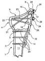
- FIG. 1is a diagrammatic, sectional view showing an intramedullary implant according to the invention installed at a fracture site in a bone.
- FIG. 2is similar to FIG. 1 and illustrates means for securing the implant to the bone fragments of the fracture.
- FIG. 3is an end view looking distally into the radial styloid of the bone fragment.
- FIG. 4is a top view of the implant.
- FIG. 5is a perspective view of the implant.
- FIG. 6is a side view showing a first embodiment of a connection between distal and proximal portions of the implant.
- FIG. 6Aillustrates, on enlarged scale, the first embodiment of the connection between the distal and proximal portions of the implant.
- FIGS. 7 , 7 A and 7 Bdiagrammatically illustrate another embodiment of the connection between the distal and proximal portions of the implant.
- FIG. 8illustrates another embodiment of the installation of the implant.
- FIG. 9is a sectional view, similar to FIG. 2 , and shows a modified installation of one of the crossing fasteners in the implant.
- FIGS. 10–17show successive stages in the installation of the fracture fixation device.
- the inventionwill be described hereafter with reference to fixation of a fracture of the radius of the wrist utilizing an intramedullary implant which is braced against the apex of the lower tip of the radial styloid to serve as a prop or buttressing means to hold an unstable fragment of the fracture at length to prevent shortening.
- the inventionis applicable to other fractures as well, in which the implant can be inserted into an intramedullary canal and braced in an inner apical surface of a bone fragment adjoining the fracture. Suitable examples are the distal end of the fibula, the medial malleolus of the ankle and the distal end of the ulna.
- a bone 1namely the radius of the wrist, in which a fracture 2 is present at its distal end and forms a stable proximal bone fragment 3 and an unstable distal bone fragment 4 .
- the distal bone fragment 4has a distal end 5 which includes the radial styloid 6 .
- the fracture 2is illustrated in proximity to the distal end 5 , the fracture can also be displaced proximally without altering the inventive concept.
- the inventionis based on utilizing an implant 10 which enters into the intramedullary canal 11 of the bone to engage an endosteal apical surface 12 at a corner at the tip of the radial styloid 6 to engage and brace the radial styloid and suspend it in a fixed position to prevent shortening or collapse of the radial styloid.
- the implant 10is axially loaded to prevent shortening of the unstable bone fragment 4 .
- the implantalso can oppose lateral drift and rotation of the radial styloid.
- the implant 10has a proximal portion 13 and a distal portion 14 .
- the proximal portionis disposed outside the bone and is engaged on and secured to the proximal, stable bone fragment 3 (as will be explained in more detail later).
- the distal portion 14is sized and shaped for entry into the intramedullary canal 11 and it has a distal end or tip 15 of particular shape to be fitted into the space defined by the endosteal apical surface 12 for bearing against the subchondral part of the radial styloid of the unstable bone fragment 4 from therewithin, to buttress the unstable bone fragment over a large surface area thereof.
- the tip 15 of the distal portion 14 of the implant 10is tapered and rounded in a bullet-like shape to provide substantial congruency with the shape of the endosteal apical surface 12 at the subchondral bone at the apical corner of the radial styloid.
- the distal portion 14widens and becomes thicker at it extends from the proximal portion 13 and it has a rounded cross-section which is oval as seen in FIG. 3 .
- the tip 15has an enlarged or blunt end as compared to conventional buttress plates or wires to provide a large bearing area against the bone to prevent penetration and perforation through the subchondral bone of the distal fragment.
- the tip endcan be symmetrical or asymmetrical for conforming to the shape of the apical corner of the subchondral bone.
- the implant 10has a slender, elongated shape; the proximal portion 13 has an approximate rectangular cross-section and it can be flat or slightly curved in order to be mounted on and secured to the outer surface of the proximal stable bone fragment, usually the shaft of the radius. This is the external part of the implant which extends at the outer surface of the bone.
- the proximal portion 13merges into the distal portion 14 which extends into the intramedullary canal 11 .
- the distal portion 14becomes wider and thicker than the proximal portion and its cross-section becomes rounded and can have an oval shape.
- the distal portion 14is offset from the proximal portion 13 and its oval shape enables it to pass through the intramedullary canal and lie against the inner surface of the cortex.
- the tip 15is shaped to enter the space defined by the apical space 12 and provide a broad support function over a large area.
- the tip 15has a rounded, tapered shape of bullet-like form.
- the tip 15has a parabolic, ogival contour adapted to provide congruency with the endosteal apical surface 12 to enable the implant to hold the distal fragment at length and prevent shortening or collapse thereof while also providing restraint against lateral and rotational movement of the distal fragment.
- FIG. 2shows an installed state of the implant 10 for fixation of fracture 2 .
- the proximal portion 13 of the implant 10is fixed to the stable, proximal fragment 3 by bone fixation screws 20 .
- the crossing fastenerscan be in the form of pins, wires, rods, pegs or screws.
- the crossing fastenerscan be smooth over their entire length or they can have threaded portions at their ends for threadably engaging the distal portion 14 and/or they can have threaded portions at or near their advancing ends for threadably engaging the bone.
- the choice of the particular crossing fastenersis made by the surgeon depending on the circumstances of the particular case, such as patient age, bone fragility, geometry of the radial styloid, etc.
- crossing fastenerswill be described as conventional pegs, which are widely used for fixation purposes, but this is in not limiting as to the particular fasteners as explained above.
- the crossing pegs 21 , 22 and 23are disposed in different planes at different angles to lock the distal portion 14 in place and prevent relative movement between the distal portion 14 and the distal fragment 4 .
- the peg 23may be inclined volarly and the peg 22 inclined dorsally.
- the pegsmay be provided with washers 24 , such as shown with pegs 21 and 23 in FIG. 2 which are seated under heads 26 , to prevent over compression of the bone by the heads 26 on the pegs while other pegs, such as peg 22 , may be inserted flush with the surface of the implant 14 .
- Two or more washersmay be integrated into a single common plate in order to engage the heads of more than one fastener with a single washer.
- the peg 22is engaged in the bone via a bearing 25 which is provided with longitudinal slits around its periphery so as to be expandable when the peg is inserted into a hole in the bearing.
- the bearinghas a generally spherical outer surface which matches with an inner spherical surface of a hole, in the bone in which the bearing is seated.
- the peg 22can be partially inserted into the bone and the angular position of the peg can be adjusted by rotation of the bearing in the bone to finalize the position of the radial styloid when setting the fracture.
- the peg 22has a tapered thread in proximity to the head 26 thereon so that when the peg 22 is fully inserted into the bearing, the bearing 25 is expanded and is locked in the hole in the bone.
- the bearingmay have a tab extending from its surface that engages a slot in the hole in the end of the implant to prevent rotation of the bearing as the peg is advanced, and/or limit a range of insertion angles of the peg to a predefined range.
- the implant 10can be made as a one-piece integral body of a light weight, strong metal, such as, titanium or stainless steel. It can also be made in two parts to enable longitudinal, translational, or rotational adjustment of the proximal and distal portions of the implant or it can be made as an independent modular assembly of different lengths of the proximal and distal portions in order to reduce inventory.
- the implantcan be made in two parts which are rotatably adjustable to enable the implant to be fixed to the dorsal or volar surface of the bone.
- FIGS. 6 and 6Ashow one embodiment of an adjustable connection 30 between the proximal portion 13 and the distal portion 14 .
- the connection 30is in the form of a Morse taper which includes a conical portion 31 on one of the portions (here the distal portion 14 ) and a conical recess 32 on the proximal portion 13 .
- the arrangementcan be reversed and the conical portion can be placed on the proximal portion and the recess on the distal portion.
- the angles of conicity of the portions 31 and 21differ by a small amount, for example, 2 to 3 degrees, whereby the distal and the proximal portions can be tightly engaged at adjusted axial or angular positions by axially forcing conical portion 31 into conical recess 32 .
- ridges and corresponding valleyscan be provided on the tapered surfaces to limit the torsional position of the proximal and distal portions to a set of predetermined rotational positions.
- a tongue in groove connection 40is provided between the opposed ends of the proximal and distal portions 13 and 14 .
- a groove 41is provided in one of the portions of the implant (in this case distal portion 14 ) and a tongue 42 is provided on the proximal portion 13 .
- the tongue 42is slidable in the groove 41 and is secured in an axially adjusted position by a machine screw 43 , which can be inserted in one of a plurality of holes 44 or in a slotted hole.
- FIG. 8therein is shown a two part connection in which the proximal portion 13 of the implant 10 is secured to the bone through a connecting plate 50 .
- the connecting plate 50is disposed on the volar surface of the bone and fixed to the bone, and the distal portion 14 enters the intramedullary canal from the lateral (or radial) side of the bone, where the bone flairs out wider at 51 .
- the connecting plate 50is of L-shape and wraps around the volar surface of the radius to join the two bone fragments 3 , 4 together.
- the plate 50is secured to the implant by connecting screws 52 and the plate has holes 53 for bone screws (not shown) for securing the plate to the bone fragments.
- the installation of the implantis carried out as shown in FIGS. 10–17 .
- a slot 60is produced along the mid-radial line of the radial shaft of the radius just proximal to the fracture 2 .
- the slotallows seating of the proximal portion 13 of the implant and avoids radial translation of the distal fragment.
- the slotis approximately 4 to 5 mm wide and 1 cm in length, and the slot deepens toward the fracture site.
- the slot 60may be prepared with either a high speed burr, or other suitable instrument.
- FIG. 11shows an awl 61 inserted along the subcortical bone of the radial styloid to the tip of the radial styloid.
- the position of the tipis confirmed on an image intensifier (not shown) and a determination is made of the proper length implant to be used.
- the awlmay be cannulated so as to be placed over a guide wire to ensure proper orientation.
- FIG. 12shows an alignment jig 62 attached to the implant and the implant is inserted into the prepared intramedullary canal in the radial styloid of the unstable fragment.
- the position of the proximal portion 13 of the implantis aligned so that a referencing arm of the alignment jig is dorsal to the tendons of the first dorsal compartment, and the pointer is aimed at the distal tip.
- a holeis then drilled in the proximal cortex and tapped and a bone screw is inserted into a slotted hole at the proximal portion of the implant.
- the screwis positioned in a central location of the slotted hole to allow fine adjustment of the position of the implant.
- a distal targeting device 64is firmly attached to the radial styloid as shown in FIG. 14 to allow placement of the interlocking transstyloid pegs.
- An outer targeting sleeve 65 and drill guide 66are assembled on the distal targeting device, as shown in FIG. 15 , and a hole is drilled for placement of a peg.
- An image intensifieris used to confirm the appropriate position prior to placement of the peg.
- an appropriate length peg and washeris inserted through the outer sleeve.
- the end of the pegis threaded to screw into the threaded hole in the implant. Care is taken to position the peg to avoid contact with the tendons.
- the proximal holes for the pegsmay be used with a washer to provide a buttress to the radial column, or the peg may be used without a washer and locked directly into the implant.
- Additional interlocking transstyloid pegs and bone screwsare applied as needed as shown in FIG. 17 .
- additional supplemental fixations with other elementsare used as necessary.
- the machine thread on the pegstops 1–2 mm short of the head of the peg. This allows insertion of the peg with a washer but prevents excessive compression from causing the washer to crack through the bone.
- Pegsmay be designed to have either a smooth or threaded surface along the leading shaft portion of the peg (not shown).
Landscapes
- Health & Medical Sciences (AREA)
- Surgery (AREA)
- Orthopedic Medicine & Surgery (AREA)
- Life Sciences & Earth Sciences (AREA)
- Biomedical Technology (AREA)
- Public Health (AREA)
- Veterinary Medicine (AREA)
- Engineering & Computer Science (AREA)
- Nuclear Medicine, Radiotherapy & Molecular Imaging (AREA)
- Heart & Thoracic Surgery (AREA)
- Medical Informatics (AREA)
- Molecular Biology (AREA)
- Animal Behavior & Ethology (AREA)
- General Health & Medical Sciences (AREA)
- Dentistry (AREA)
- Oral & Maxillofacial Surgery (AREA)
- Neurology (AREA)
- Prostheses (AREA)
- Surgical Instruments (AREA)
Abstract
Description
Claims (59)
Priority Applications (6)
| Application Number | Priority Date | Filing Date | Title |
|---|---|---|---|
| US10/675,864US7267678B2 (en) | 2003-09-30 | 2003-09-30 | Intramedullary implant for fracture fixation |
| CA002540578ACA2540578A1 (en) | 2003-09-30 | 2004-06-25 | An intramedullary implant for fracture fixation |
| AU2004279312AAU2004279312A1 (en) | 2003-09-30 | 2004-06-25 | An intramedullary implant for fracture fixation |
| JP2006533822AJP2007507285A (en) | 2003-09-30 | 2004-06-25 | Intramedullary implant for fracture fixation |
| EP04756244AEP1675515A4 (en) | 2003-09-30 | 2004-06-25 | An intramedullary implant for fracture fixation |
| PCT/US2004/020684WO2005034794A2 (en) | 2003-09-30 | 2004-06-25 | An intramedullary implant for fracture fixation |
Applications Claiming Priority (1)
| Application Number | Priority Date | Filing Date | Title |
|---|---|---|---|
| US10/675,864US7267678B2 (en) | 2003-09-30 | 2003-09-30 | Intramedullary implant for fracture fixation |
Publications (2)
| Publication Number | Publication Date |
|---|---|
| US20050070902A1 US20050070902A1 (en) | 2005-03-31 |
| US7267678B2true US7267678B2 (en) | 2007-09-11 |
Family
ID=34377291
Family Applications (1)
| Application Number | Title | Priority Date | Filing Date |
|---|---|---|---|
| US10/675,864Expired - Fee RelatedUS7267678B2 (en) | 2003-09-30 | 2003-09-30 | Intramedullary implant for fracture fixation |
Country Status (6)
| Country | Link |
|---|---|
| US (1) | US7267678B2 (en) |
| EP (1) | EP1675515A4 (en) |
| JP (1) | JP2007507285A (en) |
| AU (1) | AU2004279312A1 (en) |
| CA (1) | CA2540578A1 (en) |
| WO (1) | WO2005034794A2 (en) |
Cited By (27)
| Publication number | Priority date | Publication date | Assignee | Title |
|---|---|---|---|---|
| US20070233106A1 (en)* | 2006-02-24 | 2007-10-04 | Synthes (Usa) | Tibal plateau leveling osteotomy plate |
| US20090048600A1 (en)* | 2007-06-22 | 2009-02-19 | Anthem Orthopaedics Van, Llc | Intramedullary rod with pivotable fastener and method for using same |
| US8128627B2 (en) | 2007-03-22 | 2012-03-06 | Sonoma Orthopedic Products, Inc. | Segmented intramedullary system and apparatus |
| US8267972B1 (en)* | 2006-12-01 | 2012-09-18 | Gehlert Rick J | Bone plate |
| US8287538B2 (en) | 2008-01-14 | 2012-10-16 | Conventus Orthopaedics, Inc. | Apparatus and methods for fracture repair |
| US8303589B2 (en) | 2008-06-24 | 2012-11-06 | Extremity Medical Llc | Fixation system, an intramedullary fixation assembly and method of use |
| US8313487B2 (en) | 2008-06-24 | 2012-11-20 | Extremity Medical Llc | Fixation system, an intramedullary fixation assembly and method of use |
| US8328806B2 (en) | 2008-06-24 | 2012-12-11 | Extremity Medical, Llc | Fixation system, an intramedullary fixation assembly and method of use |
| US8343199B2 (en) | 2008-06-24 | 2013-01-01 | Extremity Medical, Llc | Intramedullary fixation screw, a fixation system, and method of fixation of the subtalar joint |
| US20130046349A1 (en)* | 2008-05-05 | 2013-02-21 | Trimed, Incorporated | Contoured bone plate for fracture fixation having hook members and holder/impactor for same |
| US8591554B2 (en) | 2010-05-07 | 2013-11-26 | Osteomed Llc | System for treating bone fractures |
| US8790343B2 (en) | 2008-10-11 | 2014-07-29 | Epix Orthopaedics, Inc. | Intramedullary rod with pivotable and fixed fasteners and method for using same |
| US8906022B2 (en) | 2010-03-08 | 2014-12-09 | Conventus Orthopaedics, Inc. | Apparatus and methods for securing a bone implant |
| US8961518B2 (en) | 2010-01-20 | 2015-02-24 | Conventus Orthopaedics, Inc. | Apparatus and methods for bone access and cavity preparation |
| US9017329B2 (en) | 2008-06-24 | 2015-04-28 | Extremity Medical, Llc | Intramedullary fixation assembly and method of use |
| US9044282B2 (en) | 2008-06-24 | 2015-06-02 | Extremity Medical Llc | Intraosseous intramedullary fixation assembly and method of use |
| US9289220B2 (en) | 2008-06-24 | 2016-03-22 | Extremity Medical Llc | Intramedullary fixation assembly and method of use |
| US9730739B2 (en) | 2010-01-15 | 2017-08-15 | Conventus Orthopaedics, Inc. | Rotary-rigid orthopaedic rod |
| US9833270B2 (en) | 2013-09-19 | 2017-12-05 | Mcginley Engineered Solutions, Llc | Variable angle blade plate system and method |
| US9861418B2 (en) | 2012-02-08 | 2018-01-09 | Epix Orthopaedics, Inc. | Implant insertion device with continuously adjustable targeting assembly |
| US10022132B2 (en) | 2013-12-12 | 2018-07-17 | Conventus Orthopaedics, Inc. | Tissue displacement tools and methods |
| US10123828B2 (en) | 2013-03-15 | 2018-11-13 | Epix Orthopaedics, Inc. | Implantable device with pivotable fastener and self-adjusting set screw |
| US10918426B2 (en) | 2017-07-04 | 2021-02-16 | Conventus Orthopaedics, Inc. | Apparatus and methods for treatment of a bone |
| US11490906B2 (en) | 2013-11-08 | 2022-11-08 | Trimed Incorporated | Drill guides and inserters for bone plates having hook members |
| US11596419B2 (en) | 2017-03-09 | 2023-03-07 | Flower Orthopedics Corporation | Plating depth gauge and countersink instrument |
| US11963847B2 (en) | 2021-11-03 | 2024-04-23 | DePuy Synthes Products, Inc. | TPLO plate compression system and method |
| US12402923B2 (en) | 2022-10-04 | 2025-09-02 | DePuy Synthes Products, Inc. | Offset hole for TPLO compression |
Families Citing this family (28)
| Publication number | Priority date | Publication date | Assignee | Title |
|---|---|---|---|---|
| US7635365B2 (en) | 2003-08-28 | 2009-12-22 | Ellis Thomas J | Bone plates |
| US20050055024A1 (en)* | 2003-09-08 | 2005-03-10 | James Anthony H. | Orthopaedic implant and screw assembly |
| US7799030B2 (en)* | 2003-09-08 | 2010-09-21 | Smith & Nephew, Inc. | Orthopaedic plate and screw assembly |
| US7780667B2 (en) | 2003-09-08 | 2010-08-24 | Smith & Nephew, Inc. | Orthopaedic plate and screw assembly |
| US20060036248A1 (en)* | 2004-07-01 | 2006-02-16 | Ferrante Joseph M | Fixation elements |
| US20080249580A1 (en)* | 2005-09-28 | 2008-10-09 | Smith & Nephew, Inc. | Methods and Instruments of Reducing a Fracture |
| US20070155271A1 (en)* | 2005-12-30 | 2007-07-05 | Touzov Igor V | Heat conductive textile and method producing thereof |
| US20070173835A1 (en)* | 2006-01-13 | 2007-07-26 | Medoff Robert J | Intramedullary implant for fracture fixation and method of using the same |
| US20100016983A1 (en)* | 2006-04-13 | 2010-01-21 | Arno Smit | Hip protector implant |
| US7918853B2 (en)* | 2007-03-20 | 2011-04-05 | Smith & Nephew, Inc. | Orthopaedic plate and screw assembly |
| US8652179B2 (en)* | 2008-05-02 | 2014-02-18 | The Cleveland Clinic Foundation | Bone plate extender and extension system for bone restoration and methods of use thereof |
| US8915918B2 (en)* | 2008-05-02 | 2014-12-23 | Thomas James Graham | Bone plate system for bone restoration and methods of use thereof |
| US8608783B2 (en)* | 2008-05-08 | 2013-12-17 | The Cleveland Clinic Foundation | Bone plate with flange member and methods of use thereof |
| US8628533B2 (en)* | 2008-05-08 | 2014-01-14 | The Cleveland Clinic Foundation | Bone plate with reduction aids and methods of use thereof |
| US8167952B2 (en)* | 2008-09-03 | 2012-05-01 | The Cleveland Clinic Foundation | Arthroplastic implant with shield for basilar joint and related methods |
| US8343228B2 (en)* | 2008-09-03 | 2013-01-01 | The Cleveland Clinic Foundation | Arthroplastic implant with anchor peg for basilar joint and related methods |
| US8231625B2 (en)* | 2008-09-03 | 2012-07-31 | The Cleveland Clinic Foundation | Modular bone fixation device for treatment of fractures and related methods |
| US8506641B2 (en)* | 2008-09-03 | 2013-08-13 | The Cleveland Clinic Foundation | Arthrodesis implant for finger joints and related methods |
| US9237910B2 (en) | 2012-01-26 | 2016-01-19 | Acute Innovations Llc | Clip for rib stabilization |
| US12285197B2 (en) | 2008-10-10 | 2025-04-29 | Acumed Llc | Bone fixation system with opposed mounting portions |
| US8449544B2 (en) | 2009-06-30 | 2013-05-28 | Smith & Nephew, Inc. | Orthopaedic implant and fastener assembly |
| US8834469B2 (en) | 2009-06-30 | 2014-09-16 | Smith & Nephew, Inc. | Orthopaedic implant and fastener assembly |
| US8568417B2 (en) | 2009-12-18 | 2013-10-29 | Charles River Engineering Solutions And Technologies, Llc | Articulating tool and methods of using |
| US8647391B2 (en) | 2010-07-07 | 2014-02-11 | Global Orthopaedic Solutions Llc | Malleolar replacement devices |
| WO2013049849A2 (en) | 2011-09-30 | 2013-04-04 | Acute Innovations, Llc, An Oregon Limited Liability Company | Bone fixation system with opposed mounting portions |
| US10226292B2 (en)* | 2015-06-08 | 2019-03-12 | Andrew Lundquist | Combined intramedullary-extramedullary bone stabilization and alignment system |
| US10517655B2 (en) | 2015-06-08 | 2019-12-31 | Andrew Lundquist | Combined intramedullary-extramedullary bone stabilization and alignment system |
| CN114145807A (en)* | 2021-12-07 | 2022-03-08 | 自贡市第一人民医院 | Temporal bone styloid process truncator |
Citations (4)
| Publication number | Priority date | Publication date | Assignee | Title |
|---|---|---|---|---|
| US3763855A (en)* | 1972-03-15 | 1973-10-09 | Atee R Mc | Device for fixation of bone fractures |
| US4438762A (en)* | 1981-12-30 | 1984-03-27 | Richard F. Kyle | Orthopedic hip fixation device |
| US6033407A (en)* | 1998-01-27 | 2000-03-07 | Behrens; Alfred F. | Apparatus and method for intramedullary nailing and intramedullary nail therefor |
| US6527775B1 (en)* | 2000-09-22 | 2003-03-04 | Piper Medical, Inc. | Intramedullary interlocking fixation device for the distal radius |
Family Cites Families (4)
| Publication number | Priority date | Publication date | Assignee | Title |
|---|---|---|---|---|
| SE460014B (en)* | 1986-01-31 | 1989-09-04 | John Stefan Nilsson | FIXATION DEVICE FOR LABOR FRACTURES |
| DE4209122A1 (en)* | 1992-03-20 | 1993-09-23 | Kessler Sigurd | MARKING NAIL |
| US6355041B1 (en)* | 2001-01-30 | 2002-03-12 | Board Of Supervisors Of Louisiana State University And Agricultural And Mechanical College | Bone pin-plate surgical device and method for promoting athrodesis of the equine fetlock joint |
| DE10201743C2 (en)* | 2002-01-18 | 2003-12-18 | Aesculap Ag & Co Kg | Intramedullary osteosynthesis implant |
- 2003
- 2003-09-30USUS10/675,864patent/US7267678B2/ennot_activeExpired - Fee Related
- 2004
- 2004-06-25EPEP04756244Apatent/EP1675515A4/ennot_activeWithdrawn
- 2004-06-25AUAU2004279312Apatent/AU2004279312A1/ennot_activeAbandoned
- 2004-06-25JPJP2006533822Apatent/JP2007507285A/enactivePending
- 2004-06-25WOPCT/US2004/020684patent/WO2005034794A2/enactiveApplication Filing
- 2004-06-25CACA002540578Apatent/CA2540578A1/ennot_activeAbandoned
Patent Citations (4)
| Publication number | Priority date | Publication date | Assignee | Title |
|---|---|---|---|---|
| US3763855A (en)* | 1972-03-15 | 1973-10-09 | Atee R Mc | Device for fixation of bone fractures |
| US4438762A (en)* | 1981-12-30 | 1984-03-27 | Richard F. Kyle | Orthopedic hip fixation device |
| US6033407A (en)* | 1998-01-27 | 2000-03-07 | Behrens; Alfred F. | Apparatus and method for intramedullary nailing and intramedullary nail therefor |
| US6527775B1 (en)* | 2000-09-22 | 2003-03-04 | Piper Medical, Inc. | Intramedullary interlocking fixation device for the distal radius |
Cited By (58)
| Publication number | Priority date | Publication date | Assignee | Title |
|---|---|---|---|---|
| US10905479B2 (en) | 2006-02-24 | 2021-02-02 | DePuy Synthes Products, Inc. | Tibial plateau leveling osteotomy plate |
| US11026728B2 (en) | 2006-02-24 | 2021-06-08 | DePuy Synthes Products, Inc. | Tibial plateau leveling osteotomy plate |
| US11992250B2 (en) | 2006-02-24 | 2024-05-28 | DePuy Synthes Products, Inc. | Tibial plateau leveling osteotomy plate |
| US20070233106A1 (en)* | 2006-02-24 | 2007-10-04 | Synthes (Usa) | Tibal plateau leveling osteotomy plate |
| US8523921B2 (en)* | 2006-02-24 | 2013-09-03 | DePuy Synthes Products, LLC | Tibial plateau leveling osteotomy plate |
| US10786290B2 (en) | 2006-02-24 | 2020-09-29 | DePuy Synthes Products, Inc. | Tibial plateau leveling osteotomy plate |
| US8267972B1 (en)* | 2006-12-01 | 2012-09-18 | Gehlert Rick J | Bone plate |
| US8430879B2 (en) | 2007-03-22 | 2013-04-30 | Sonoma Orthopedic Products, Inc. | Segmented intramedullary structure |
| US8128627B2 (en) | 2007-03-22 | 2012-03-06 | Sonoma Orthopedic Products, Inc. | Segmented intramedullary system and apparatus |
| US8496658B2 (en) | 2007-03-22 | 2013-07-30 | Sonoma Orthopedic Products, Inc. | Segmented intramedullary structure |
| US10687871B2 (en) | 2007-06-22 | 2020-06-23 | Epix Orthopaedics, Inc. | Intramedullary rod for pivoting a fastener |
| US9861403B2 (en) | 2007-06-22 | 2018-01-09 | Epix Orthopaedics, Inc. | Method for pivoting a fastener |
| US20090048600A1 (en)* | 2007-06-22 | 2009-02-19 | Anthem Orthopaedics Van, Llc | Intramedullary rod with pivotable fastener and method for using same |
| US8906023B2 (en) | 2007-06-22 | 2014-12-09 | Epix Orthopaedics, Inc. | Intramedullary rod for pivoting a fastener |
| US8287538B2 (en) | 2008-01-14 | 2012-10-16 | Conventus Orthopaedics, Inc. | Apparatus and methods for fracture repair |
| US9788870B2 (en) | 2008-01-14 | 2017-10-17 | Conventus Orthopaedics, Inc. | Apparatus and methods for fracture repair |
| US9517093B2 (en) | 2008-01-14 | 2016-12-13 | Conventus Orthopaedics, Inc. | Apparatus and methods for fracture repair |
| US10603087B2 (en) | 2008-01-14 | 2020-03-31 | Conventus Orthopaedics, Inc. | Apparatus and methods for fracture repair |
| US11399878B2 (en) | 2008-01-14 | 2022-08-02 | Conventus Orthopaedics, Inc. | Apparatus and methods for fracture repair |
| US9283010B2 (en)* | 2008-05-05 | 2016-03-15 | Trimed, Incorporated | Contoured bone plate for fracture fixation having hook members and holder/impactor for same |
| US20130046349A1 (en)* | 2008-05-05 | 2013-02-21 | Trimed, Incorporated | Contoured bone plate for fracture fixation having hook members and holder/impactor for same |
| US8821508B2 (en) | 2008-05-05 | 2014-09-02 | Trimed, Incorporated | Holder/impactor for contoured bone plate for fracture fixation |
| US8920453B2 (en) | 2008-06-24 | 2014-12-30 | Extremity Medical, Llc | Fixation system, an intramedullary fixation assembly and method of use |
| US8343199B2 (en) | 2008-06-24 | 2013-01-01 | Extremity Medical, Llc | Intramedullary fixation screw, a fixation system, and method of fixation of the subtalar joint |
| US9044282B2 (en) | 2008-06-24 | 2015-06-02 | Extremity Medical Llc | Intraosseous intramedullary fixation assembly and method of use |
| US11974786B2 (en) | 2008-06-24 | 2024-05-07 | Extremity Medical L.L.C. | Intraosseous intramedullary fixation assembly and method of use |
| US8303589B2 (en) | 2008-06-24 | 2012-11-06 | Extremity Medical Llc | Fixation system, an intramedullary fixation assembly and method of use |
| US9289220B2 (en) | 2008-06-24 | 2016-03-22 | Extremity Medical Llc | Intramedullary fixation assembly and method of use |
| US8920476B2 (en) | 2008-06-24 | 2014-12-30 | Extremity Medical, Llc | Fixation system, an intramedullary fixation assembly and method of use |
| US10751097B2 (en) | 2008-06-24 | 2020-08-25 | Extremity Medical Llc | Intraosseous intramedullary fixation assembly and method of use |
| US11298166B2 (en) | 2008-06-24 | 2022-04-12 | Extremity Medical Llc | Intraosseous intramedullary fixation assembly and method of use |
| US8313487B2 (en) | 2008-06-24 | 2012-11-20 | Extremity Medical Llc | Fixation system, an intramedullary fixation assembly and method of use |
| US8900274B2 (en) | 2008-06-24 | 2014-12-02 | Extremity Medical Llc | Fixation system, an intramedullary fixation assembly and method of use |
| US8328806B2 (en) | 2008-06-24 | 2012-12-11 | Extremity Medical, Llc | Fixation system, an intramedullary fixation assembly and method of use |
| US9017329B2 (en) | 2008-06-24 | 2015-04-28 | Extremity Medical, Llc | Intramedullary fixation assembly and method of use |
| US8790343B2 (en) | 2008-10-11 | 2014-07-29 | Epix Orthopaedics, Inc. | Intramedullary rod with pivotable and fixed fasteners and method for using same |
| US9730739B2 (en) | 2010-01-15 | 2017-08-15 | Conventus Orthopaedics, Inc. | Rotary-rigid orthopaedic rod |
| US9848889B2 (en) | 2010-01-20 | 2017-12-26 | Conventus Orthopaedics, Inc. | Apparatus and methods for bone access and cavity preparation |
| US8961518B2 (en) | 2010-01-20 | 2015-02-24 | Conventus Orthopaedics, Inc. | Apparatus and methods for bone access and cavity preparation |
| US9993277B2 (en) | 2010-03-08 | 2018-06-12 | Conventus Orthopaedics, Inc. | Apparatus and methods for securing a bone implant |
| US8906022B2 (en) | 2010-03-08 | 2014-12-09 | Conventus Orthopaedics, Inc. | Apparatus and methods for securing a bone implant |
| US8591554B2 (en) | 2010-05-07 | 2013-11-26 | Osteomed Llc | System for treating bone fractures |
| US10111688B2 (en) | 2010-05-07 | 2018-10-30 | Mcginley Engineered Solutions, Llc | System for treating bone fractures |
| US8603148B2 (en) | 2010-05-07 | 2013-12-10 | Raymond B. Raven, III | System for treating bone fractures |
| US9066766B2 (en) | 2010-05-07 | 2015-06-30 | Osteomed Llc | System for treating bone fractures |
| US9649141B2 (en) | 2010-05-07 | 2017-05-16 | Mcginley Engineered Solutions, Llc | System for treating bone fractures |
| US9295506B2 (en) | 2010-05-07 | 2016-03-29 | Osteomed Llc | System for treating bone fractures |
| US9861418B2 (en) | 2012-02-08 | 2018-01-09 | Epix Orthopaedics, Inc. | Implant insertion device with continuously adjustable targeting assembly |
| US10123828B2 (en) | 2013-03-15 | 2018-11-13 | Epix Orthopaedics, Inc. | Implantable device with pivotable fastener and self-adjusting set screw |
| US10117689B2 (en) | 2013-09-19 | 2018-11-06 | Mcginley Engineered Solutions, Llc | Variable angle blade plate system and method |
| US9833270B2 (en) | 2013-09-19 | 2017-12-05 | Mcginley Engineered Solutions, Llc | Variable angle blade plate system and method |
| US11490906B2 (en) | 2013-11-08 | 2022-11-08 | Trimed Incorporated | Drill guides and inserters for bone plates having hook members |
| US10022132B2 (en) | 2013-12-12 | 2018-07-17 | Conventus Orthopaedics, Inc. | Tissue displacement tools and methods |
| US10076342B2 (en) | 2013-12-12 | 2018-09-18 | Conventus Orthopaedics, Inc. | Tissue displacement tools and methods |
| US11596419B2 (en) | 2017-03-09 | 2023-03-07 | Flower Orthopedics Corporation | Plating depth gauge and countersink instrument |
| US10918426B2 (en) | 2017-07-04 | 2021-02-16 | Conventus Orthopaedics, Inc. | Apparatus and methods for treatment of a bone |
| US11963847B2 (en) | 2021-11-03 | 2024-04-23 | DePuy Synthes Products, Inc. | TPLO plate compression system and method |
| US12402923B2 (en) | 2022-10-04 | 2025-09-02 | DePuy Synthes Products, Inc. | Offset hole for TPLO compression |
Also Published As
| Publication number | Publication date |
|---|---|
| EP1675515A4 (en) | 2008-08-06 |
| WO2005034794A3 (en) | 2005-09-29 |
| CA2540578A1 (en) | 2005-04-21 |
| AU2004279312A1 (en) | 2005-04-21 |
| EP1675515A2 (en) | 2006-07-05 |
| JP2007507285A (en) | 2007-03-29 |
| US20050070902A1 (en) | 2005-03-31 |
| WO2005034794A2 (en) | 2005-04-21 |
Similar Documents
| Publication | Publication Date | Title |
|---|---|---|
| US7267678B2 (en) | Intramedullary implant for fracture fixation | |
| EP1507486B1 (en) | Intramedullary fixation device for metaphyseal long bone fractures | |
| US7909858B2 (en) | Bone plate systems using provisional fixation | |
| JP5215285B2 (en) | Modular fracture fixation plate system | |
| USRE43482E1 (en) | Intramedullary rod apparatus and methods of repairing proximal humerus fractures | |
| US6409730B1 (en) | Humeral spiral blade | |
| KR101524518B1 (en) | Bone plates and bone plate assemblies | |
| CA2587373C (en) | Endosteal nail | |
| EP1713410B1 (en) | Proximal humeral fracture fixation system comprising a plate including a post rotationally locked in a post hole, and a rigid cross support | |
| US8216238B2 (en) | Method of using an intramedullary implant for fracture fixation | |
| JP5231207B2 (en) | Modular fracture fixation plate system | |
| US20060161156A1 (en) | Fracture fixation device | |
| US20070225714A1 (en) | System for the Minimally Invasive Treatment of a Bone Fracture, Especially of a Proximal Humeral or Femoral Fracture | |
| US20040193155A1 (en) | Fracture fixation plate with particular plate hole and fastener engagement and methods of using the same | |
| EP4306067A1 (en) | Bone plate |
Legal Events
| Date | Code | Title | Description |
|---|---|---|---|
| AS | Assignment | Owner name:TRIMED, INC., CALIFORNIA Free format text:ASSIGNMENT OF ASSIGNORS INTEREST;ASSIGNOR:MEFOFF, ROBERT J.;REEL/FRAME:014924/0776 Effective date:20031104 | |
| AS | Assignment | Owner name:TELLMAN, LARS G., SWEDEN Free format text:ASSIGNMENT OF ASSIGNORS INTEREST;ASSIGNOR:TRIMED, INC.;REEL/FRAME:015117/0119 Effective date:20040803 Owner name:MEDOFF, ROBERT J., HAWAII Free format text:ASSIGNMENT OF ASSIGNORS INTEREST;ASSIGNOR:TRIMED, INC.;REEL/FRAME:015117/0119 Effective date:20040803 Owner name:MEDOFF, DAVID, CALIFORNIA Free format text:ASSIGNMENT OF ASSIGNORS INTEREST;ASSIGNOR:TRIMED, INC.;REEL/FRAME:015117/0119 Effective date:20040803 | |
| REMI | Maintenance fee reminder mailed | ||
| LAPS | Lapse for failure to pay maintenance fees | ||
| STCH | Information on status: patent discontinuation | Free format text:PATENT EXPIRED DUE TO NONPAYMENT OF MAINTENANCE FEES UNDER 37 CFR 1.362 | |
| FP | Lapsed due to failure to pay maintenance fee | Effective date:20110911 | |
| AS | Assignment | Owner name:TRIMED INC., CALIFORNIA Free format text:ASSIGNMENT OF ASSIGNORS INTEREST;ASSIGNORS:MEDOFF, ROBERT J.;TELLMAN, LARS G.;MEDOFF, DAVID;REEL/FRAME:065473/0468 Effective date:20231105 | |
| AS | Assignment | Owner name:TRIMED, INC., CALIFORNIA Free format text:CHANGE OF NAME;ASSIGNOR:TRIMED INC.;REEL/FRAME:068916/0799 Effective date:20240816 |