US7267647B2 - Endoscope - Google Patents
EndoscopeDownload PDFInfo
- Publication number
- US7267647B2 US7267647B2US10/774,540US77454004AUS7267647B2US 7267647 B2US7267647 B2US 7267647B2US 77454004 AUS77454004 AUS 77454004AUS 7267647 B2US7267647 B2US 7267647B2
- Authority
- US
- United States
- Prior art keywords
- optical system
- inserting tube
- tip
- endoscope according
- magnification
- Prior art date
- Legal status (The legal status is an assumption and is not a legal conclusion. Google has not performed a legal analysis and makes no representation as to the accuracy of the status listed.)
- Expired - Lifetime, expires
Links
Images


Classifications
- A—HUMAN NECESSITIES
- A61—MEDICAL OR VETERINARY SCIENCE; HYGIENE
- A61B—DIAGNOSIS; SURGERY; IDENTIFICATION
- A61B1/00—Instruments for performing medical examinations of the interior of cavities or tubes of the body by visual or photographical inspection, e.g. endoscopes; Illuminating arrangements therefor
- A61B1/00163—Optical arrangements
- A61B1/00174—Optical arrangements characterised by the viewing angles
- A61B1/00181—Optical arrangements characterised by the viewing angles for multiple fixed viewing angles
- A—HUMAN NECESSITIES
- A61—MEDICAL OR VETERINARY SCIENCE; HYGIENE
- A61B—DIAGNOSIS; SURGERY; IDENTIFICATION
- A61B1/00—Instruments for performing medical examinations of the interior of cavities or tubes of the body by visual or photographical inspection, e.g. endoscopes; Illuminating arrangements therefor
- A61B1/00064—Constructional details of the endoscope body
- A61B1/00071—Insertion part of the endoscope body
- A61B1/0008—Insertion part of the endoscope body characterised by distal tip features
- A61B1/00096—Optical elements
- A—HUMAN NECESSITIES
- A61—MEDICAL OR VETERINARY SCIENCE; HYGIENE
- A61B—DIAGNOSIS; SURGERY; IDENTIFICATION
- A61B1/00—Instruments for performing medical examinations of the interior of cavities or tubes of the body by visual or photographical inspection, e.g. endoscopes; Illuminating arrangements therefor
- A61B1/04—Instruments for performing medical examinations of the interior of cavities or tubes of the body by visual or photographical inspection, e.g. endoscopes; Illuminating arrangements therefor combined with photographic or television appliances
- A61B1/05—Instruments for performing medical examinations of the interior of cavities or tubes of the body by visual or photographical inspection, e.g. endoscopes; Illuminating arrangements therefor combined with photographic or television appliances characterised by the image sensor, e.g. camera, being in the distal end portion
Definitions
- the present inventionrelates to endoscopes having optical systems.
- An endoscopeis generally provided with an observing optical system, which is used for observing in vivo tissues inside a human cavity.
- an objective optical systemis provided as the observing optical system, and an image of a target portion (e.g., tissues in the human cavity) is formed on a solid state image capturing element such as a CCD (Charge Coupled Device).
- CCDCharge Coupled Device
- the confocal probeis typically inserted in an accessory channel of the endoscope, and is used to observe a minute object which cannot be observed using the normal observing optical system of the endoscope.
- the confocal probeis also used for obtaining an optical tomography of the in vivo tissues.
- An example of such a confocal probeis disclosed in Japanese Patent Provisional Publication No. P2000-121961A.
- the confocal probeis inserted through the accessory channel to obtain a high magnification image of the affected portion, which enables more precise inspection thereof.
- the present inventionis advantageous in that an endoscope is provided, which includes two optical systems that have different magnifications, and a positional relationship between the areas observed using the two optical systems can be recognized without difficulties.
- an endoscopewhich is provided with an inserting tube to be inserted into a human body, a first optical system secured in a tip end of the inserting tube for observing in vivo tissues within a human body at first magnification, and a second optical system secured in the tip end of the inserting tube for observing the in vivo tissues at second magnification that is higher than the first magnification.
- a portion of the second optical systemmay be located within the field of view of the first optical system.
- the endoscopemay include a tip body mounted on a distal end of the inserting tube to hold the first optical system and the second optical systems at fixed positions.
- first optical system and the second optical systemmay be provided on an end surface of the tip body, and at least a front end portion of the second optical system is protruded with respect to the first optical system.
- the first optical systemmay be arranged such that a front end portion is substantially flush with respect to the end surface of the tip body.
- an optical axis of the first optical system and an optical axis of the second optical systemmay be substantially parallel with each other.
- the second optical systemis arranged not to interfere with a central area of the field of view of the first optical system.
- At least a part of the cover membermay be observable in the field of view of the first optical system.
- the part of the cover memberdoes not interfere with a central area of the field of view of the first optical system.
- the cover member of the tip bodydoes not intersect a horizontal centerline and a vertical centerline of the field of view of the first optical system.
- the cover member of the tip bodymay surround at least a part of a circumferential surface of the end portion of the second optical system.
- the tip bodymay be made of hard resin.
- an outer surface of the cover member of the tip bodymay be tapered.
- the tip bodymay be formed with an outlet of a forceps channel for introducing a forceps into the human body.
- the cover member of the tip bodymay be formed not to interfere with the forceps protruded from the outlet.
- the second optical systemis a confocal optical system.
- the endoscopemay include an imaging device provided in the tip end of the inserting tube, and
- the endoscopemay include an optical fiber that transmits light returned from the in vivo tissues.
- the second optical systemmay be arranged such that only the light from a level of a focal plane of the second optical system is transmitted through the optical fiber.
- an endoscopewhich includes an inserting tube to be inserted into a human body, a first optical system secured in a tip end of the inserting tube for observing in vivo tissues within a human body at first magnification, and a second optical system secured in the tip end of the inserting tube for observing the in vivo tissues at second magnification that is higher than the first magnification.
- an endoscopewhich is provided with an inserting tube to be inserted into a human body, a first optical system secured in a tip end of the flexible inserting tube for observing in vivo tissues within a human body at first magnification, and a second optical system secured in the tip end of the flexible inserting tube for observing the in vivo tissues at second magnification that is higher than the first magnification.
- the first optical system and the second optical systemare arranged such that a front end portion of the second optical system is within a field of view of the first optical system.
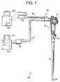
- FIG. 1schematically shows an electronic endoscope system according to an embodiment of the invention
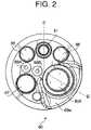
- FIG. 2is a front view of a tip end of a flexible inserting tube of an electronic endoscope shown in FIG. 1 ;
- FIG. 3is a sectional view of the tip end of the flexible inserting tube shown in FIG. 2 taken along line III-III;
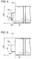
- FIG. 4shows a side view of a tip end of the flexible inserting tube shown in FIG. 2 ;
- FIG. 5shows a side view of a tip end according to a modification of the embodiment.
- FIGS. 6A and 6Bshow images displayed on a monitor of the electronic endoscope system shown in FIG. 1 .
- FIG. 1schematically shows an electronic endoscope system 500 according to the embodiment of the invention.
- the electronic endoscope system 500includes an electronic endoscope 100 , a first processor 210 , a second processor 220 , a first monitor 310 and a second monitor 320 .
- the electronic endoscope 100includes a first optical system for observing in vivo tissues inside the human body at a low magnification and a second optical system for observing the in vivo tissues at a high magnification.
- the first processor 210processes and displays the low magnification image on the first monitor 310 .
- the second processor 220processes and displays the high magnification image on the second monitor 320 .
- the electronic endoscope 100includes a flexible inserting tube 10 , which is to be inserted into a human body, and an operation portion 30 fixed on a proximal end of the flexible inserting tube 10 .
- the electronic endoscope 100further includes a universal cord 40 and a confocal system cord 60 , both extending from the operating portion 30 .
- the universal cord 40is connected with the first processor 210 through an endoscope connector 50 provided on the end of the universal cord 40 .
- the confocal system cord 60is connected with the second processor 220 through a confocal system connector 70 provided on the end of the confocal system cord 60 .
- the operating portion 30is provided with multiple knobs 31 , which are manipulated for controlling bending direction and angle of the flexible inserting tube 10 to observe a desired portion inside the human body with the electronic endoscope 100 or to treat them with the forceps.
- FIG. 2is a front view of the tip end 80 of the flexible inserting tube 10
- FIG. 3is a sectional view of the tip end 80 taken along a line III-III in FIG. 2 .
- a tip body 89made of hard resin, for example, is fixed on the tip end 80 of the flexible inserting tube 10 .
- the front face 81 a of the tip body 89is provided with two illumination windows 86 (see FIG. 2 ) through which light is emitted onto a target (e.g., tissues to be observed) 400 , a forceps channel opening 87 through which the forceps is protruded, and an air feeding opening 88 A and a water feeding opening 88 B for feeding air and water to the target 400 , respectively.
- the confocal unit 85includes an optical fiber 82 and an objective lens system (the second objective lens system) 850 for observing the target 400 at a high magnification.
- the second objective lens system 850has a glass cover 84 at the front end thereof for protecting other optical elements of the second objective lens system 850 .
- the confocal unit 85holds an optical fiber 82 so that a distal end face 82 a thereof is on a rear focal plane of the second objective lens system 850 .
- the optical fiber 82is a single mode optical fiber connected to the confocal system cord 60 that is connected to the second processor 220 with the confocal system connector 70 .
- the optical fiber 82extends from the tip end 80 , through the flexible inserting tube 10 and the operation portion 30 .
- the confocal unit 85further includes an actuator 802 , such as a piezoelectric actuator, for moving the distal end face 82 a of the optical fiber 82 .
- an actuator 802such as a piezoelectric actuator, for moving the distal end face 82 a of the optical fiber 82 .
- a laser beamis emitted from the distal end face 82 a of the optical fiber 82 and irradiated on the target 400 through the second optical system 850 .
- the actuator 802swings the distal end face 82 a of the optical fiber 82 so that the laser beam scans on the target 400 .
- the first processor 210is provided with a not shown light source.
- the light emitted from the light sourceis transmitted through two light guides (not shown) extending through the electronic endoscope 100 (i.e., the universal cord 40 , the operation portion 30 , and the flexible inserting tube 10 ) and emitted from the illumination windows 86 to illuminate the target 400 .
- the first optical system 810forms an image of the illuminated target 400 on the solid-state imaging device 811 .
- the solid-state imaging device 811converts the optical image into an image signal and sends it to the first processor 210 through a signal line 813 (see FIG. 3 ) extending through the electronic endoscope 100 (i.e., the flexible inserting tube 10 , the operation portion 30 , and the universal cord 40 ).
- the first processor 210receives the image signal and generates a video signal, which is sent to the first monitor 310 to display the low magnification image captured by the solid-state imaging device 811 .
- the second processor 220is provided with a not shown laser source.
- the laser beam emitted from the laser sourceis introduced into the optical fiber 82 of the electronic endoscope 100 through the confocal system connector 70 .
- the laser beamtransmits through the optical fiber 82 and emerges from the distal end face 82 a thereof to proceed toward the second optical system 850 .
- the second optical system 850focuses the light to a small spot on the target 400 , which is located on the front focal plane of the second optical system 850 .
- Light returned from the illuminated spot on the target 400is collected by the second objective optical system 850 and converged onto the distal end face 82 a of the optical fiber 82 .
- the light returned from the illuminated spot on the target 400can be either reflected light or fluorescence light emanating from the tissues.
- the distal end face 82 a of the optical fiber 82is located on the rear focal plane of the second optical system 850 .
- the distal end face 82 ais conjugate to the illuminated spot on the target 400 with respect to the second objective optical system 850 .
- the core of the optical fiber 82is quite small, the core serves as a confocal pin hole, which allows only the light from the spot on the target 400 to enter the optical fiber 82 and to block light that did not originate from the spot.
- the second objective lens system 850converges light from the target 400 at a level of the front focal plane thereof on a distal end face 82 a of the optical fiber 82 .
- the returned light introduced into the optical fiber 82transmits therethrough to the second processor 220 .
- the second processor 220includes a not shown photosensor, which detects the intensity of the light transmitted through the optical fiber 82 .
- the distal end of the optical fiber 82is moved by the actuator 802 so that the laser beam scans the target 400 .
- the optical characteristic of the target 400which is in vivo tissues in the present embodiment, varies with the location thereon, the intensity of the light reflected by the target 400 varies as the laser beam is scanned.
- the second processor 220can generate an optical tomography of the target 400 based on the intensity of the light received through the optical fiber 82 . The optical tomography is then displayed on the second monitor 310 .
- the tip body 89is mounted on the tip end 80 of the flexible inserting tube 10 .
- the endoscope unit 81is held by the tip body 89 such that the front face of the first optical system 810 is substantially flush with the front face 81 a of the tip body 89 .
- the confocal unit 85is disposed such that a front end portion 85 a thereof protrudes from the front face 81 a of the tip body 89 .
- the confocal unit 85is disposed such that the second optical system 850 is slightly protruded forward with respect to the first optical system 810 .
- FIG. 4is a side view of the tip end 80 of the flexible inserting tube 10 .
- the tip body 89has a diameter of ⁇ D B , in which the first objective lens system 810 and the second objective lens system 850 are held.
- the confocal unit 85includes a barrel member in which the optical elements of the second optical system 850 are secured.
- the front end portion 85 a of the second objective lens system 850i.e., the barrel member
- has a diameter of ⁇ D Awhich is smaller than ⁇ D B , as shown in FIG. 4 , and is protruded forward with respect to the front face 81 a of the tip body 89 .
- the front face 85 b of the front end portion 85 acontacts the target 400 .
- the front face 81 a of the tip body 89does not contact the target 400 due to the protruded structure of the confocal unit 85 . Since the positional relationship of the second objective lens unit 850 with respect to the electronic endoscope 100 is fixed, the user can have the confocal unit 85 (i.e., the front face of the second objective lens unit 850 , or the protruded portion 85 a ) contact the target 400 stably.
- the first lens unit 810is located on the operation portion side of the endoscope 100 with respect to the second lens unit 850 , an insertion length of the tip body having the diameter of ⁇ D B can be reduced.
- the reduced amountis compensated by the portion of the tip body 89 having a smaller diameter (i.e., the protruded portion 85 a ).
- the tip body 89is made of hard resin. Therefore, by forming the tip portion to have a smaller diameter than the rear portion (whose diameter is ⁇ D B ), load to a patient can be well reduced.
- the front face 81 a of the tip body 89is partially protruded to form a cover portion 89 a that surrounds the circumferential surface of the front end portion 85 a of the confocal unit 85 .
- the cover portion 89 aprotects the front end portion 85 a of the confocal unit 85 , which is thin and week, so that a large force will not be applied thereto directly.
- the cover portion 89 ais tapered toward the front end thereof.
- the cover portion 89 awhich protrudes from the front face 81 a of the tip end 80 , does not cause damage to a body even when the flexible inserting tube 10 is inserted into a narrow space of the body.
- FIG. 5shows a side view of the tip end 80 according to a modification of the embodiment.
- the cover portion 89 ais not provided, and only the front end portion 85 a of the second objective lens unit 850 is protruded with respect to the front face 81 a of the tip body 89 .
- the tip end portion 85 a of the tip body 89has a smaller diameter (i.e., ⁇ D A ) than the rear portion (whose diameter is ⁇ D B ), load to a patient can be reduced.
- FIGS. 6A and 6Bshow the first monitor 310 displaying the image captured through the first optical system 81 .
- the confocal unit 85 and the cover portion 89 a of the tip body 89are arranged such that they are partially located within the image displayed on the first monitor 310 , or within the view filed of the first optical system 81 .
- the confocal unit 85 and the cover portion 89 a of the tip body 89are also arranged such that they do not interfere with the central area of the image displayed on the first monitor 310 , which is the most suitable area for observation.
- the confocal unit 85 and the cover portion 89 a of the tip body 89are arranged such that they do not intersect a horizontal center line 310 a and a vertical center line 310 b defined on the screen of the first monitor 310 (or the view field of the first optical system 81 ).
- the arrangement described aboveallows the operator to observe the target 400 at the center of the screen of the first monitor 310 , while confirming the position of the confocal unit 85 at the peripheral of the screen.
- the confocal unit 85is also located apart enough from the forceps channel opening 87 to prevent it from interfering with the operation of the forceps protruding from forceps channel opening 87 .
- a low magnification image of the target 400which is obtained using the first optical system 810 , is displayed on the first monitor 310 .
- the operatorobserves the target 400 at the central area of the screen of the first monitor 310 while confirming the position of the confocal unit 85 at the peripheral of the screen, as shown in FIG. 6A . This allows the operator to easily determine the positional relationship between the target 400 and the area that can be observed through the confocal unit 85 .
- the operatormanipulates the electronic endoscope 100 so that the target 400 is located in front of the confocal unit 85 , as shown in FIG. 6B .
- a high magnification image of the target 400is obtained through the confocal unit 85 and displayed on the second monitor 320 .
- the high magnification imageallows the operator to inspect the target 400 in detail.
- the operatorcan locate the target 400 in front of the confocal unit 85 quickly and precisely, which reduces the time required for endoscopic inspection and operation.
Landscapes
- Health & Medical Sciences (AREA)
- Life Sciences & Earth Sciences (AREA)
- Surgery (AREA)
- Nuclear Medicine, Radiotherapy & Molecular Imaging (AREA)
- Biomedical Technology (AREA)
- Optics & Photonics (AREA)
- Pathology (AREA)
- Radiology & Medical Imaging (AREA)
- Biophysics (AREA)
- Engineering & Computer Science (AREA)
- Physics & Mathematics (AREA)
- Heart & Thoracic Surgery (AREA)
- Medical Informatics (AREA)
- Molecular Biology (AREA)
- Animal Behavior & Ethology (AREA)
- General Health & Medical Sciences (AREA)
- Public Health (AREA)
- Veterinary Medicine (AREA)
- Endoscopes (AREA)
Abstract
Description
- the first optical system may form an image of a target on the imaging device.
Claims (19)
Applications Claiming Priority (4)
| Application Number | Priority Date | Filing Date | Title |
|---|---|---|---|
| JP2003-031817 | 2003-02-10 | ||
| JP2003031817 | 2003-02-10 | ||
| JP2003138099 | 2003-05-16 | ||
| JP2003-138099 | 2003-05-16 |
Publications (2)
| Publication Number | Publication Date |
|---|---|
| US20040158129A1 US20040158129A1 (en) | 2004-08-12 |
| US7267647B2true US7267647B2 (en) | 2007-09-11 |
Family
ID=32737723
Family Applications (1)
| Application Number | Title | Priority Date | Filing Date |
|---|---|---|---|
| US10/774,540Expired - LifetimeUS7267647B2 (en) | 2003-02-10 | 2004-02-10 | Endoscope |
Country Status (2)
| Country | Link |
|---|---|
| US (1) | US7267647B2 (en) |
| DE (1) | DE102004006541B4 (en) |
Cited By (52)
| Publication number | Priority date | Publication date | Assignee | Title |
|---|---|---|---|---|
| US20050052753A1 (en)* | 2003-09-05 | 2005-03-10 | Pentax Corporation | Condensing optical system, confocal optical system, and scanning confocal endoscope |
| US20060235273A1 (en)* | 2003-12-15 | 2006-10-19 | Olympus Corporation | Endoscope system and endoscope |
| US20070055106A1 (en)* | 2004-04-27 | 2007-03-08 | Hiroki Moriyama | Endoscope and endoscope system |
| US20070260119A1 (en)* | 2005-01-07 | 2007-11-08 | Olympus Medical Systems Corp. | Endoscope insertion portion |
| US20080080051A1 (en)* | 2006-09-28 | 2008-04-03 | Pentax Corporation | Distal end optical unit for electronic endoscope |
| US20080200764A1 (en)* | 2007-02-15 | 2008-08-21 | Pentax Corporation | Endoscope system |
| US20080269563A1 (en)* | 2007-04-27 | 2008-10-30 | Susumu Takahashi | Illumination light application structure and endoscope provided with the same |
| US20090048490A1 (en)* | 2006-04-24 | 2009-02-19 | Olympus Medical Systems Corp. | Endoscope |
| US20090093681A1 (en)* | 2006-06-15 | 2009-04-09 | Hironobu Ichimura | Endoscope |
| US20090124856A1 (en)* | 2005-04-11 | 2009-05-14 | Takashi Otawara | Endoscope Insertion Portion |
| US20100292535A1 (en)* | 2009-05-18 | 2010-11-18 | Larry Paskar | Endoscope with multiple fields of view |
| US20110280810A1 (en)* | 2010-03-12 | 2011-11-17 | Carl Zeiss Meditec, Inc. | Surgical optical systems for detecting brain tumors |
| US20110282155A1 (en)* | 2009-11-06 | 2011-11-17 | Olympus Medical Systems Corp. | Endoscope |
| US20120157773A1 (en)* | 2010-07-08 | 2012-06-21 | Olympus Medical Systems Corp. | Endoscope |
| CN102707427A (en)* | 2011-03-28 | 2012-10-03 | 富士胶片株式会社 | Endoscope and lighting optical device thereof |
| US20140155694A1 (en)* | 2012-07-03 | 2014-06-05 | Olympus Medical Systems Corp. | Endoscope Objective Optical System |
| US8764632B2 (en) | 2010-04-08 | 2014-07-01 | Eric James Kezirian | Endoscopic device and system |
| US8926502B2 (en) | 2011-03-07 | 2015-01-06 | Endochoice, Inc. | Multi camera endoscope having a side service channel |
| US9101266B2 (en) | 2011-02-07 | 2015-08-11 | Endochoice Innovation Center Ltd. | Multi-element cover for a multi-camera endoscope |
| US9101287B2 (en) | 2011-03-07 | 2015-08-11 | Endochoice Innovation Center Ltd. | Multi camera endoscope assembly having multiple working channels |
| US9101268B2 (en) | 2009-06-18 | 2015-08-11 | Endochoice Innovation Center Ltd. | Multi-camera endoscope |
| US9314147B2 (en) | 2011-12-13 | 2016-04-19 | Endochoice Innovation Center Ltd. | Rotatable connector for an endoscope |
| US9320419B2 (en) | 2010-12-09 | 2016-04-26 | Endochoice Innovation Center Ltd. | Fluid channeling component of a multi-camera endoscope |
| US9402533B2 (en) | 2011-03-07 | 2016-08-02 | Endochoice Innovation Center Ltd. | Endoscope circuit board assembly |
| US9492063B2 (en) | 2009-06-18 | 2016-11-15 | Endochoice Innovation Center Ltd. | Multi-viewing element endoscope |
| US9554692B2 (en) | 2009-06-18 | 2017-01-31 | EndoChoice Innovation Ctr. Ltd. | Multi-camera endoscope |
| US9560954B2 (en) | 2012-07-24 | 2017-02-07 | Endochoice, Inc. | Connector for use with endoscope |
| US9560953B2 (en) | 2010-09-20 | 2017-02-07 | Endochoice, Inc. | Operational interface in a multi-viewing element endoscope |
| US9642513B2 (en) | 2009-06-18 | 2017-05-09 | Endochoice Inc. | Compact multi-viewing element endoscope system |
| US9655502B2 (en) | 2011-12-13 | 2017-05-23 | EndoChoice Innovation Center, Ltd. | Removable tip endoscope |
| US9706903B2 (en) | 2009-06-18 | 2017-07-18 | Endochoice, Inc. | Multiple viewing elements endoscope system with modular imaging units |
| US9713417B2 (en) | 2009-06-18 | 2017-07-25 | Endochoice, Inc. | Image capture assembly for use in a multi-viewing elements endoscope |
| US9814374B2 (en) | 2010-12-09 | 2017-11-14 | Endochoice Innovation Center Ltd. | Flexible electronic circuit board for a multi-camera endoscope |
| US9872609B2 (en) | 2009-06-18 | 2018-01-23 | Endochoice Innovation Center Ltd. | Multi-camera endoscope |
| US9901244B2 (en) | 2009-06-18 | 2018-02-27 | Endochoice, Inc. | Circuit board assembly of a multiple viewing elements endoscope |
| US9986899B2 (en) | 2013-03-28 | 2018-06-05 | Endochoice, Inc. | Manifold for a multiple viewing elements endoscope |
| US9993142B2 (en) | 2013-03-28 | 2018-06-12 | Endochoice, Inc. | Fluid distribution device for a multiple viewing elements endoscope |
| US10064545B2 (en) | 2012-10-18 | 2018-09-04 | The Arizona Board Of Regents On Behalf Of The University Of Arizona | Multi-resolution foveated endoscope/laparoscope |
| US10080486B2 (en) | 2010-09-20 | 2018-09-25 | Endochoice Innovation Center Ltd. | Multi-camera endoscope having fluid channels |
| US10165929B2 (en) | 2009-06-18 | 2019-01-01 | Endochoice, Inc. | Compact multi-viewing element endoscope system |
| US10203493B2 (en) | 2010-10-28 | 2019-02-12 | Endochoice Innovation Center Ltd. | Optical systems for multi-sensor endoscopes |
| US10499794B2 (en) | 2013-05-09 | 2019-12-10 | Endochoice, Inc. | Operational interface in a multi-viewing element endoscope |
| US11278190B2 (en) | 2009-06-18 | 2022-03-22 | Endochoice, Inc. | Multi-viewing element endoscope |
| US11547275B2 (en) | 2009-06-18 | 2023-01-10 | Endochoice, Inc. | Compact multi-viewing element endoscope system |
| US11864734B2 (en) | 2009-06-18 | 2024-01-09 | Endochoice, Inc. | Multi-camera endoscope |
| US11874452B2 (en) | 2013-06-26 | 2024-01-16 | Alentic Microscience Inc. | Sample processing improvements for microscopy |
| US11889986B2 (en) | 2010-12-09 | 2024-02-06 | Endochoice, Inc. | Flexible electronic circuit board for a multi-camera endoscope |
| US11947096B2 (en) | 2009-10-28 | 2024-04-02 | Alentic Microscience Inc. | Microscopy imaging |
| US12022236B2 (en) | 2009-10-28 | 2024-06-25 | Alentic Microscience Inc. | Detecting and using light representative of a sample |
| US12137873B2 (en) | 2009-06-18 | 2024-11-12 | Endochoice, Inc. | Compact multi-viewing element endoscope system |
| US12204087B2 (en) | 2010-10-28 | 2025-01-21 | Endochoice, Inc. | Optical systems for multi-sensor endoscopes |
| US12220105B2 (en) | 2010-06-16 | 2025-02-11 | Endochoice, Inc. | Circuit board assembly of a multiple viewing elements endoscope |
Families Citing this family (53)
| Publication number | Priority date | Publication date | Assignee | Title |
|---|---|---|---|---|
| JP3870911B2 (en)* | 2003-02-10 | 2007-01-24 | 日産自動車株式会社 | Lane departure prevention device |
| DE102004035269A1 (en)* | 2004-07-21 | 2006-02-16 | Rowiak Gmbh | Laryngoscope with OCT |
| WO2006056014A1 (en)* | 2004-11-25 | 2006-06-01 | Optiscan Pty Ltd | Endoscope |
| WO2006073186A1 (en) | 2005-01-07 | 2006-07-13 | Olympus Medical Systems Corp. | Endoscope-use insertion unit |
| JP4542438B2 (en)* | 2005-01-17 | 2010-09-15 | オリンパスメディカルシステムズ株式会社 | Endoscope insertion part and endoscope |
| JP4754871B2 (en)* | 2005-05-11 | 2011-08-24 | オリンパスメディカルシステムズ株式会社 | End of the endoscope |
| JP4875319B2 (en)* | 2005-06-20 | 2012-02-15 | オリンパスメディカルシステムズ株式会社 | Endoscope |
| JP4745808B2 (en)* | 2005-12-06 | 2011-08-10 | Hoya株式会社 | Magnifying endoscope |
| JP4999046B2 (en) | 2006-04-05 | 2012-08-15 | Hoya株式会社 | Confocal endoscope system |
| JP4823755B2 (en)* | 2006-04-27 | 2011-11-24 | 富士フイルム株式会社 | Lens system assembly method and interval setting jig |
| JP5030507B2 (en)* | 2006-08-30 | 2012-09-19 | オリンパスメディカルシステムズ株式会社 | Endoscope tip hood and endoscope with hood |
| EP2140292B1 (en)* | 2007-03-31 | 2017-03-01 | Koninklijke Philips N.V. | Optical biopsy device |
| US20100171820A1 (en)* | 2007-06-28 | 2010-07-08 | Koninklijke Philips Electronics N.V. | Lens system |
| EP2385406A4 (en)* | 2009-01-21 | 2017-03-22 | Olympus Corporation | Optical element and optical unit using the same |
| US10524645B2 (en) | 2009-06-18 | 2020-01-07 | Endochoice, Inc. | Method and system for eliminating image motion blur in a multiple viewing elements endoscope |
| US10130246B2 (en) | 2009-06-18 | 2018-11-20 | Endochoice, Inc. | Systems and methods for regulating temperature and illumination intensity at the distal tip of an endoscope |
| US9474440B2 (en) | 2009-06-18 | 2016-10-25 | Endochoice, Inc. | Endoscope tip position visual indicator and heat management system |
| JP5554153B2 (en) | 2010-06-11 | 2014-07-23 | 富士フイルム株式会社 | Endoscope |
| GB2484482B (en)* | 2010-10-11 | 2014-07-02 | Sensor Coating Systems Ltd | Detection System |
| US9706908B2 (en) | 2010-10-28 | 2017-07-18 | Endochoice, Inc. | Image capture and video processing systems and methods for multiple viewing element endoscopes |
| US10663714B2 (en) | 2010-10-28 | 2020-05-26 | Endochoice, Inc. | Optical system for an endoscope |
| US11304590B2 (en) | 2011-02-07 | 2022-04-19 | Endochoice, Inc. | Illuminator circuit board assembly for an endoscope |
| US10517464B2 (en) | 2011-02-07 | 2019-12-31 | Endochoice, Inc. | Multi-element cover for a multi-camera endoscope |
| US20170325665A1 (en)* | 2011-02-07 | 2017-11-16 | Endochoice, Inc. | Illuminator Circuit Board Assembly for An Endoscope |
| EP2929830B1 (en)* | 2012-12-05 | 2018-10-10 | Olympus Corporation | Endoscope apparatus |
| US12207796B2 (en) | 2013-03-28 | 2025-01-28 | Endochoice Inc. | Multi-jet controller for an endoscope |
| US9636003B2 (en) | 2013-06-28 | 2017-05-02 | Endochoice, Inc. | Multi-jet distributor for an endoscope |
| US10595714B2 (en) | 2013-03-28 | 2020-03-24 | Endochoice, Inc. | Multi-jet controller for an endoscope |
| WO2014182723A1 (en) | 2013-05-07 | 2014-11-13 | Endochoice, Inc. | White balance enclosed for use with a multi-viewing elements endoscope |
| US9949623B2 (en) | 2013-05-17 | 2018-04-24 | Endochoice, Inc. | Endoscope control unit with braking system |
| US10064541B2 (en) | 2013-08-12 | 2018-09-04 | Endochoice, Inc. | Endoscope connector cover detection and warning system |
| US9943218B2 (en) | 2013-10-01 | 2018-04-17 | Endochoice, Inc. | Endoscope having a supply cable attached thereto |
| US9968242B2 (en) | 2013-12-18 | 2018-05-15 | Endochoice, Inc. | Suction control unit for an endoscope having two working channels |
| WO2015112747A2 (en) | 2014-01-22 | 2015-07-30 | Endochoice, Inc. | Image capture and video processing systems and methods for multiple viewing element endoscopes |
| JP2015202241A (en)* | 2014-04-15 | 2015-11-16 | Hoya株式会社 | endoscope apparatus |
| US11234581B2 (en) | 2014-05-02 | 2022-02-01 | Endochoice, Inc. | Elevator for directing medical tool |
| EP3689219B1 (en) | 2014-07-21 | 2023-08-30 | EndoChoice, Inc. | Multi-focal, multi-camera endoscope systems |
| US10542877B2 (en) | 2014-08-29 | 2020-01-28 | Endochoice, Inc. | Systems and methods for varying stiffness of an endoscopic insertion tube |
| EP3235241B1 (en) | 2014-12-18 | 2023-09-06 | EndoChoice, Inc. | System for processing video images generated by a multiple viewing elements endoscope |
| WO2016112034A2 (en) | 2015-01-05 | 2016-07-14 | Endochoice, Inc. | Tubed manifold of a multiple viewing elements endoscope |
| JP6435349B2 (en)* | 2015-02-06 | 2018-12-05 | オリンパス株式会社 | Optical fiber scanner and scanning endoscope apparatus |
| US10376181B2 (en) | 2015-02-17 | 2019-08-13 | Endochoice, Inc. | System for detecting the location of an endoscopic device during a medical procedure |
| US10078207B2 (en) | 2015-03-18 | 2018-09-18 | Endochoice, Inc. | Systems and methods for image magnification using relative movement between an image sensor and a lens assembly |
| US10401611B2 (en) | 2015-04-27 | 2019-09-03 | Endochoice, Inc. | Endoscope with integrated measurement of distance to objects of interest |
| US10516865B2 (en) | 2015-05-17 | 2019-12-24 | Endochoice, Inc. | Endoscopic image enhancement using contrast limited adaptive histogram equalization (CLAHE) implemented in a processor |
| US20170119474A1 (en) | 2015-10-28 | 2017-05-04 | Endochoice, Inc. | Device and Method for Tracking the Position of an Endoscope within a Patient's Body |
| EP4579310A3 (en) | 2015-11-24 | 2025-09-10 | Endochoice, Inc. | Disposable air/water and suction valves for an endoscope |
| JP6211236B1 (en)* | 2015-12-25 | 2017-10-11 | オリンパス株式会社 | Endoscope and endoscope objective optical unit |
| JP2019507628A (en) | 2016-02-24 | 2019-03-22 | エンドチョイス インコーポレイテッドEndochoice, Inc. | Circuit board assembly for multiple view element endoscopes using CMOS sensors |
| US10292570B2 (en) | 2016-03-14 | 2019-05-21 | Endochoice, Inc. | System and method for guiding and tracking a region of interest using an endoscope |
| EP3429478B1 (en) | 2016-06-21 | 2021-04-21 | Endochoice, Inc. | Endoscope system with multiple connection interfaces to interface with different video data signal sources |
| WO2018122916A1 (en)* | 2016-12-26 | 2018-07-05 | オリンパス株式会社 | Optical fiber scanning device and endoscope |
| EP3613327A1 (en) | 2018-08-24 | 2020-02-26 | Ambu A/S | A tip part for a vision device |
Citations (15)
| Publication number | Priority date | Publication date | Assignee | Title |
|---|---|---|---|---|
| US3643653A (en)* | 1968-12-24 | 1972-02-22 | Olympus Optical Co | Endoscopic apparatus |
| US3889662A (en)* | 1973-05-31 | 1975-06-17 | Olympus Optical Co | Endoscope |
| US4279247A (en)* | 1978-07-27 | 1981-07-21 | Olympus Optical Co., Ltd. | Endoscope having a plurality of optical systems each provided with an identification mark element |
| US4593682A (en)* | 1983-09-28 | 1986-06-10 | Richard Wolf Gmbh | Endoscope |
| US4790295A (en)* | 1986-12-16 | 1988-12-13 | Olympus Optical Co., Ltd. | Endoscope having transparent resin sealing layer |
| US5120953A (en) | 1988-07-13 | 1992-06-09 | Harris Martin R | Scanning confocal microscope including a single fibre for transmitting light to and receiving light from an object |
| US5193525A (en)* | 1990-11-30 | 1993-03-16 | Vision Sciences | Antiglare tip in a sheath for an endoscope |
| US5323009A (en) | 1990-04-06 | 1994-06-21 | Harris Martin R | Conforcal microscope |
| US5846185A (en)* | 1996-09-17 | 1998-12-08 | Carollo; Jerome T. | High resolution, wide field of view endoscopic viewing system |
| US5989185A (en)* | 1994-11-25 | 1999-11-23 | Olympus Optical Co., Ltd. | Endoscope apparatus |
| JP2000121961A (en) | 1998-10-13 | 2000-04-28 | Olympus Optical Co Ltd | Confocal optical scanning probe system |
| US6066090A (en)* | 1997-06-19 | 2000-05-23 | Yoon; Inbae | Branched endoscope system |
| US20020099267A1 (en)* | 2001-01-25 | 2002-07-25 | Scimed Life Systems, Inc. | Endoscopic vision system |
| US6530882B1 (en)* | 2000-06-30 | 2003-03-11 | Inner Vision Imaging, L.L.C. | Endoscope having microscopic and macroscopic magnification |
| US20040122290A1 (en)* | 2001-03-30 | 2004-06-24 | Irion Klaus M. | Endoscopic visualization apparatus with different imaging systems |
Family Cites Families (2)
| Publication number | Priority date | Publication date | Assignee | Title |
|---|---|---|---|---|
| JPH0921963A (en)* | 1995-07-10 | 1997-01-21 | Hitachi Ltd | Endoscope device |
| JP2001311880A (en)* | 2000-04-28 | 2001-11-09 | Olympus Optical Co Ltd | Compact confocal optical system |
- 2004
- 2004-02-10USUS10/774,540patent/US7267647B2/ennot_activeExpired - Lifetime
- 2004-02-10DEDE102004006541.1Apatent/DE102004006541B4/ennot_activeExpired - Lifetime
Patent Citations (15)
| Publication number | Priority date | Publication date | Assignee | Title |
|---|---|---|---|---|
| US3643653A (en)* | 1968-12-24 | 1972-02-22 | Olympus Optical Co | Endoscopic apparatus |
| US3889662A (en)* | 1973-05-31 | 1975-06-17 | Olympus Optical Co | Endoscope |
| US4279247A (en)* | 1978-07-27 | 1981-07-21 | Olympus Optical Co., Ltd. | Endoscope having a plurality of optical systems each provided with an identification mark element |
| US4593682A (en)* | 1983-09-28 | 1986-06-10 | Richard Wolf Gmbh | Endoscope |
| US4790295A (en)* | 1986-12-16 | 1988-12-13 | Olympus Optical Co., Ltd. | Endoscope having transparent resin sealing layer |
| US5120953A (en) | 1988-07-13 | 1992-06-09 | Harris Martin R | Scanning confocal microscope including a single fibre for transmitting light to and receiving light from an object |
| US5323009A (en) | 1990-04-06 | 1994-06-21 | Harris Martin R | Conforcal microscope |
| US5193525A (en)* | 1990-11-30 | 1993-03-16 | Vision Sciences | Antiglare tip in a sheath for an endoscope |
| US5989185A (en)* | 1994-11-25 | 1999-11-23 | Olympus Optical Co., Ltd. | Endoscope apparatus |
| US5846185A (en)* | 1996-09-17 | 1998-12-08 | Carollo; Jerome T. | High resolution, wide field of view endoscopic viewing system |
| US6066090A (en)* | 1997-06-19 | 2000-05-23 | Yoon; Inbae | Branched endoscope system |
| JP2000121961A (en) | 1998-10-13 | 2000-04-28 | Olympus Optical Co Ltd | Confocal optical scanning probe system |
| US6530882B1 (en)* | 2000-06-30 | 2003-03-11 | Inner Vision Imaging, L.L.C. | Endoscope having microscopic and macroscopic magnification |
| US20020099267A1 (en)* | 2001-01-25 | 2002-07-25 | Scimed Life Systems, Inc. | Endoscopic vision system |
| US20040122290A1 (en)* | 2001-03-30 | 2004-06-24 | Irion Klaus M. | Endoscopic visualization apparatus with different imaging systems |
Cited By (100)
| Publication number | Priority date | Publication date | Assignee | Title |
|---|---|---|---|---|
| US7338439B2 (en)* | 2003-09-05 | 2008-03-04 | Pentax Corporation | Condensing optical system, confocal optical system, and scanning confocal endoscope |
| US20050052753A1 (en)* | 2003-09-05 | 2005-03-10 | Pentax Corporation | Condensing optical system, confocal optical system, and scanning confocal endoscope |
| US7914444B2 (en)* | 2003-12-15 | 2011-03-29 | Olympus Corporation | Endoscope system and endoscope |
| US20060235273A1 (en)* | 2003-12-15 | 2006-10-19 | Olympus Corporation | Endoscope system and endoscope |
| US8002697B2 (en)* | 2004-04-27 | 2011-08-23 | Olympus Corporation | Dual endoscope system with display unit |
| US20070055106A1 (en)* | 2004-04-27 | 2007-03-08 | Hiroki Moriyama | Endoscope and endoscope system |
| US20070260119A1 (en)* | 2005-01-07 | 2007-11-08 | Olympus Medical Systems Corp. | Endoscope insertion portion |
| US8092375B2 (en)* | 2005-01-07 | 2012-01-10 | Olympus Medical Systems Corp. | Endoscope insertion portion with plurality of observation windows |
| US20090124856A1 (en)* | 2005-04-11 | 2009-05-14 | Takashi Otawara | Endoscope Insertion Portion |
| US8545400B2 (en)* | 2006-04-24 | 2013-10-01 | Olympus Medical Systems Corp. | Endoscope |
| US20090048490A1 (en)* | 2006-04-24 | 2009-02-19 | Olympus Medical Systems Corp. | Endoscope |
| US20090093681A1 (en)* | 2006-06-15 | 2009-04-09 | Hironobu Ichimura | Endoscope |
| US8394013B2 (en)* | 2006-06-15 | 2013-03-12 | Olympus Medical Systems Corp. | Endoscope |
| US8360967B2 (en)* | 2006-09-28 | 2013-01-29 | Hoya Corporation | Distal end optical unit for electronic endoscope |
| US20080080051A1 (en)* | 2006-09-28 | 2008-04-03 | Pentax Corporation | Distal end optical unit for electronic endoscope |
| US20080200764A1 (en)* | 2007-02-15 | 2008-08-21 | Pentax Corporation | Endoscope system |
| US20080269563A1 (en)* | 2007-04-27 | 2008-10-30 | Susumu Takahashi | Illumination light application structure and endoscope provided with the same |
| US8409081B2 (en)* | 2007-04-27 | 2013-04-02 | Olympus Medical Systems Corp. | Illumination light application structure and endoscope provided with the same |
| US20100292535A1 (en)* | 2009-05-18 | 2010-11-18 | Larry Paskar | Endoscope with multiple fields of view |
| US12137873B2 (en) | 2009-06-18 | 2024-11-12 | Endochoice, Inc. | Compact multi-viewing element endoscope system |
| US9706903B2 (en) | 2009-06-18 | 2017-07-18 | Endochoice, Inc. | Multiple viewing elements endoscope system with modular imaging units |
| US12303106B2 (en) | 2009-06-18 | 2025-05-20 | Endochoice, Inc. | Multi-camera endoscope |
| US12336686B2 (en) | 2009-06-18 | 2025-06-24 | Endochoice, Inc. | Multi-viewing element endoscope |
| US10165929B2 (en) | 2009-06-18 | 2019-01-01 | Endochoice, Inc. | Compact multi-viewing element endoscope system |
| US10638922B2 (en) | 2009-06-18 | 2020-05-05 | Endochoice, Inc. | Multi-camera endoscope |
| US10092167B2 (en) | 2009-06-18 | 2018-10-09 | Endochoice, Inc. | Multiple viewing elements endoscope system with modular imaging units |
| US9901244B2 (en) | 2009-06-18 | 2018-02-27 | Endochoice, Inc. | Circuit board assembly of a multiple viewing elements endoscope |
| US9872609B2 (en) | 2009-06-18 | 2018-01-23 | Endochoice Innovation Center Ltd. | Multi-camera endoscope |
| US10765305B2 (en) | 2009-06-18 | 2020-09-08 | Endochoice, Inc. | Circuit board assembly of a multiple viewing elements endoscope |
| US11986155B2 (en) | 2009-06-18 | 2024-05-21 | Endochoice, Inc. | Multi-viewing element endoscope |
| US10791910B2 (en) | 2009-06-18 | 2020-10-06 | Endochoice, Inc. | Multiple viewing elements endoscope system with modular imaging units |
| US9101268B2 (en) | 2009-06-18 | 2015-08-11 | Endochoice Innovation Center Ltd. | Multi-camera endoscope |
| US9713417B2 (en) | 2009-06-18 | 2017-07-25 | Endochoice, Inc. | Image capture assembly for use in a multi-viewing elements endoscope |
| US11864734B2 (en) | 2009-06-18 | 2024-01-09 | Endochoice, Inc. | Multi-camera endoscope |
| US11547275B2 (en) | 2009-06-18 | 2023-01-10 | Endochoice, Inc. | Compact multi-viewing element endoscope system |
| US11534056B2 (en) | 2009-06-18 | 2022-12-27 | Endochoice, Inc. | Multi-camera endoscope |
| US11471028B2 (en) | 2009-06-18 | 2022-10-18 | Endochoice, Inc. | Circuit board assembly of a multiple viewing elements endoscope |
| US11278190B2 (en) | 2009-06-18 | 2022-03-22 | Endochoice, Inc. | Multi-viewing element endoscope |
| US9492063B2 (en) | 2009-06-18 | 2016-11-15 | Endochoice Innovation Center Ltd. | Multi-viewing element endoscope |
| US9554692B2 (en) | 2009-06-18 | 2017-01-31 | EndoChoice Innovation Ctr. Ltd. | Multi-camera endoscope |
| US10912445B2 (en) | 2009-06-18 | 2021-02-09 | Endochoice, Inc. | Compact multi-viewing element endoscope system |
| US10905320B2 (en) | 2009-06-18 | 2021-02-02 | Endochoice, Inc. | Multi-camera endoscope |
| US9642513B2 (en) | 2009-06-18 | 2017-05-09 | Endochoice Inc. | Compact multi-viewing element endoscope system |
| US10799095B2 (en) | 2009-06-18 | 2020-10-13 | Endochoice, Inc. | Multi-viewing element endoscope |
| US10791909B2 (en) | 2009-06-18 | 2020-10-06 | Endochoice, Inc. | Image capture assembly for use in a multi-viewing elements endoscope |
| US9706905B2 (en) | 2009-06-18 | 2017-07-18 | Endochoice Innovation Center Ltd. | Multi-camera endoscope |
| US11947096B2 (en) | 2009-10-28 | 2024-04-02 | Alentic Microscience Inc. | Microscopy imaging |
| US12022236B2 (en) | 2009-10-28 | 2024-06-25 | Alentic Microscience Inc. | Detecting and using light representative of a sample |
| US12388957B2 (en) | 2009-10-28 | 2025-08-12 | Alentic Microscience Inc. | Detecting and using light representative of a sample |
| US8343043B2 (en)* | 2009-11-06 | 2013-01-01 | Olympus Medical Systems Corp. | Endoscope |
| US9131834B2 (en) | 2009-11-06 | 2015-09-15 | Olympus Corporation | Endoscope |
| US20110282155A1 (en)* | 2009-11-06 | 2011-11-17 | Olympus Medical Systems Corp. | Endoscope |
| US9044142B2 (en)* | 2010-03-12 | 2015-06-02 | Carl Zeiss Meditec Ag | Surgical optical systems for detecting brain tumors |
| US20110280810A1 (en)* | 2010-03-12 | 2011-11-17 | Carl Zeiss Meditec, Inc. | Surgical optical systems for detecting brain tumors |
| US8764632B2 (en) | 2010-04-08 | 2014-07-01 | Eric James Kezirian | Endoscopic device and system |
| US10064683B2 (en) | 2010-04-08 | 2018-09-04 | Eric James Kezirian | Endoscopic device and system |
| US12220105B2 (en) | 2010-06-16 | 2025-02-11 | Endochoice, Inc. | Circuit board assembly of a multiple viewing elements endoscope |
| US20120157773A1 (en)* | 2010-07-08 | 2012-06-21 | Olympus Medical Systems Corp. | Endoscope |
| US9560953B2 (en) | 2010-09-20 | 2017-02-07 | Endochoice, Inc. | Operational interface in a multi-viewing element endoscope |
| US10080486B2 (en) | 2010-09-20 | 2018-09-25 | Endochoice Innovation Center Ltd. | Multi-camera endoscope having fluid channels |
| US9986892B2 (en) | 2010-09-20 | 2018-06-05 | Endochoice, Inc. | Operational interface in a multi-viewing element endoscope |
| US11543646B2 (en) | 2010-10-28 | 2023-01-03 | Endochoice, Inc. | Optical systems for multi-sensor endoscopes |
| US12204087B2 (en) | 2010-10-28 | 2025-01-21 | Endochoice, Inc. | Optical systems for multi-sensor endoscopes |
| US10203493B2 (en) | 2010-10-28 | 2019-02-12 | Endochoice Innovation Center Ltd. | Optical systems for multi-sensor endoscopes |
| US11497388B2 (en) | 2010-12-09 | 2022-11-15 | Endochoice, Inc. | Flexible electronic circuit board for a multi-camera endoscope |
| US11889986B2 (en) | 2010-12-09 | 2024-02-06 | Endochoice, Inc. | Flexible electronic circuit board for a multi-camera endoscope |
| US10182707B2 (en) | 2010-12-09 | 2019-01-22 | Endochoice Innovation Center Ltd. | Fluid channeling component of a multi-camera endoscope |
| US9814374B2 (en) | 2010-12-09 | 2017-11-14 | Endochoice Innovation Center Ltd. | Flexible electronic circuit board for a multi-camera endoscope |
| US9320419B2 (en) | 2010-12-09 | 2016-04-26 | Endochoice Innovation Center Ltd. | Fluid channeling component of a multi-camera endoscope |
| US10898063B2 (en) | 2010-12-09 | 2021-01-26 | Endochoice, Inc. | Flexible electronic circuit board for a multi camera endoscope |
| US9351629B2 (en) | 2011-02-07 | 2016-05-31 | Endochoice Innovation Center Ltd. | Multi-element cover for a multi-camera endoscope |
| US10070774B2 (en) | 2011-02-07 | 2018-09-11 | Endochoice Innovation Center Ltd. | Multi-element cover for a multi-camera endoscope |
| US9101266B2 (en) | 2011-02-07 | 2015-08-11 | Endochoice Innovation Center Ltd. | Multi-element cover for a multi-camera endoscope |
| US9854959B2 (en) | 2011-03-07 | 2018-01-02 | Endochoice Innovation Center Ltd. | Multi camera endoscope assembly having multiple working channels |
| US8926502B2 (en) | 2011-03-07 | 2015-01-06 | Endochoice, Inc. | Multi camera endoscope having a side service channel |
| US9713415B2 (en) | 2011-03-07 | 2017-07-25 | Endochoice Innovation Center Ltd. | Multi camera endoscope having a side service channel |
| US11026566B2 (en) | 2011-03-07 | 2021-06-08 | Endochoice, Inc. | Multi camera endoscope assembly having multiple working channels |
| US9402533B2 (en) | 2011-03-07 | 2016-08-02 | Endochoice Innovation Center Ltd. | Endoscope circuit board assembly |
| US9101287B2 (en) | 2011-03-07 | 2015-08-11 | Endochoice Innovation Center Ltd. | Multi camera endoscope assembly having multiple working channels |
| US10292578B2 (en) | 2011-03-07 | 2019-05-21 | Endochoice Innovation Center Ltd. | Multi camera endoscope assembly having multiple working channels |
| US20120253129A1 (en)* | 2011-03-28 | 2012-10-04 | Fujifilm Corporation | Endoscope and lighting optical device therefor |
| CN102707427A (en)* | 2011-03-28 | 2012-10-03 | 富士胶片株式会社 | Endoscope and lighting optical device thereof |
| US11291357B2 (en) | 2011-12-13 | 2022-04-05 | Endochoice, Inc. | Removable tip endoscope |
| US12290241B2 (en) | 2011-12-13 | 2025-05-06 | Endochoice, Inc. | Removable tip endoscope |
| US9314147B2 (en) | 2011-12-13 | 2016-04-19 | Endochoice Innovation Center Ltd. | Rotatable connector for an endoscope |
| US9655502B2 (en) | 2011-12-13 | 2017-05-23 | EndoChoice Innovation Center, Ltd. | Removable tip endoscope |
| US10470649B2 (en) | 2011-12-13 | 2019-11-12 | Endochoice, Inc. | Removable tip endoscope |
| US9372336B2 (en)* | 2012-07-03 | 2016-06-21 | Olympus Corporation | Endoscope objective optical system |
| US20140155694A1 (en)* | 2012-07-03 | 2014-06-05 | Olympus Medical Systems Corp. | Endoscope Objective Optical System |
| US9560954B2 (en) | 2012-07-24 | 2017-02-07 | Endochoice, Inc. | Connector for use with endoscope |
| US10064545B2 (en) | 2012-10-18 | 2018-09-04 | The Arizona Board Of Regents On Behalf Of The University Of Arizona | Multi-resolution foveated endoscope/laparoscope |
| US9986899B2 (en) | 2013-03-28 | 2018-06-05 | Endochoice, Inc. | Manifold for a multiple viewing elements endoscope |
| US11925323B2 (en) | 2013-03-28 | 2024-03-12 | Endochoice, Inc. | Fluid distribution device for a multiple viewing elements endoscope |
| US11793393B2 (en) | 2013-03-28 | 2023-10-24 | Endochoice, Inc. | Manifold for a multiple viewing elements endoscope |
| US12232699B2 (en) | 2013-03-28 | 2025-02-25 | Endochoice, Inc. | Manifold for a multiple viewing elements endoscope |
| US10925471B2 (en) | 2013-03-28 | 2021-02-23 | Endochoice, Inc. | Fluid distribution device for a multiple viewing elements endoscope |
| US10905315B2 (en) | 2013-03-28 | 2021-02-02 | Endochoice, Inc. | Manifold for a multiple viewing elements endoscope |
| US9993142B2 (en) | 2013-03-28 | 2018-06-12 | Endochoice, Inc. | Fluid distribution device for a multiple viewing elements endoscope |
| US10499794B2 (en) | 2013-05-09 | 2019-12-10 | Endochoice, Inc. | Operational interface in a multi-viewing element endoscope |
| US11874452B2 (en) | 2013-06-26 | 2024-01-16 | Alentic Microscience Inc. | Sample processing improvements for microscopy |
Also Published As
| Publication number | Publication date |
|---|---|
| US20040158129A1 (en) | 2004-08-12 |
| DE102004006541A1 (en) | 2004-08-19 |
| DE102004006541B4 (en) | 2016-11-10 |
Similar Documents
| Publication | Publication Date | Title |
|---|---|---|
| US7267647B2 (en) | Endoscope | |
| US7108657B2 (en) | Endoscopic visualization apparatus with different imaging systems | |
| US20050043584A1 (en) | Endoscope hood | |
| WO2011055613A1 (en) | Endoscope system | |
| EP2420178A1 (en) | Endoscope device and endoscope | |
| US20050038322A1 (en) | Imaging endoscope | |
| JP4648638B2 (en) | Endoscope | |
| JP5314841B2 (en) | Endoscope device and endoscope probe | |
| EP3437544B1 (en) | Needle-type endoscope | |
| JP5608580B2 (en) | Endoscope | |
| JP2017070555A (en) | Ultrasound endoscope | |
| JP5075658B2 (en) | Endoscope | |
| JP4996153B2 (en) | Endoscope device for magnification observation | |
| JP2007209450A (en) | Magnifying endoscope | |
| JP2008017938A (en) | Endoscope, tip mounting member, and endoscope apparatus having these | |
| JPH11155798A (en) | Hard endoscope | |
| JP4827546B2 (en) | Confocal endoscope device | |
| JP4981373B2 (en) | Magnifying endoscope | |
| JPH1176155A (en) | Endoscope | |
| JP4827636B2 (en) | Endoscope device for magnification observation | |
| JP2009219514A (en) | Contact magnified observation endoscope | |
| JP4436537B2 (en) | Endoscope | |
| JP2007289231A (en) | Endoscope system | |
| JP4745632B2 (en) | Endoscope insertion tube flexible tube and endoscope | |
| JP4895630B2 (en) | Endoscope device for magnification observation |
Legal Events
| Date | Code | Title | Description |
|---|---|---|---|
| AS | Assignment | Owner name:OPTISCAN PTY LTD., AUSTRALIA Free format text:ASSIGNMENT OF ASSIGNORS INTEREST;ASSIGNORS:OKADA, SHINSUKE;DELANEY, PETER MAXWELL;REEL/FRAME:014980/0646;SIGNING DATES FROM 20040127 TO 20040203 Owner name:PENTAX CORPORATION, JAPAN Free format text:ASSIGNMENT OF ASSIGNORS INTEREST;ASSIGNORS:OKADA, SHINSUKE;DELANEY, PETER MAXWELL;REEL/FRAME:014980/0646;SIGNING DATES FROM 20040127 TO 20040203 | |
| STCF | Information on status: patent grant | Free format text:PATENTED CASE | |
| FEPP | Fee payment procedure | Free format text:PAYOR NUMBER ASSIGNED (ORIGINAL EVENT CODE: ASPN); ENTITY STATUS OF PATENT OWNER: LARGE ENTITY | |
| AS | Assignment | Owner name:HOYA CORPORATION, JAPAN Free format text:MERGER;ASSIGNOR:PENTAX CORPORATION;REEL/FRAME:021118/0339 Effective date:20080331 | |
| FPAY | Fee payment | Year of fee payment:4 | |
| FPAY | Fee payment | Year of fee payment:8 | |
| MAFP | Maintenance fee payment | Free format text:PAYMENT OF MAINTENANCE FEE, 12TH YEAR, LARGE ENTITY (ORIGINAL EVENT CODE: M1553); ENTITY STATUS OF PATENT OWNER: LARGE ENTITY Year of fee payment:12 |