US7266275B2 - Nonlinear optical fibre method of its production and use thereof - Google Patents
Nonlinear optical fibre method of its production and use thereofDownload PDFInfo
- Publication number
- US7266275B2 US7266275B2US10/507,723US50772305AUS7266275B2US 7266275 B2US7266275 B2US 7266275B2US 50772305 AUS50772305 AUS 50772305AUS 7266275 B2US7266275 B2US 7266275B2
- Authority
- US
- United States
- Prior art keywords
- optical fibre
- index
- cladding features
- refractive index
- core
- Prior art date
- Legal status (The legal status is an assumption and is not a legal conclusion. Google has not performed a legal analysis and makes no representation as to the accuracy of the status listed.)
- Expired - Fee Related, expires
Links
- 239000013307optical fiberSubstances0.000titleclaimsabstractdescription84
- 238000000034methodMethods0.000titleclaimsabstractdescription18
- 238000004519manufacturing processMethods0.000titledescription6
- 238000005253claddingMethods0.000claimsabstractdescription120
- 239000000835fiberSubstances0.000claimsabstractdescription107
- 239000006185dispersionSubstances0.000claimsabstractdescription85
- 230000003287optical effectEffects0.000claimsabstractdescription20
- 238000001069Raman spectroscopyMethods0.000claimsabstractdescription14
- 238000004891communicationMethods0.000claimsabstractdescription12
- VYPSYNLAJGMNEJ-UHFFFAOYSA-NSilicium dioxideChemical compoundO=[Si]=OVYPSYNLAJGMNEJ-UHFFFAOYSA-N0.000claimsdescription36
- 239000000463materialSubstances0.000claimsdescription23
- 239000000377silicon dioxideSubstances0.000claimsdescription16
- 235000012239silicon dioxideNutrition0.000claimsdescription12
- 238000010438heat treatmentMethods0.000claimsdescription5
- 239000011162core materialSubstances0.000claims25
- 238000013461designMethods0.000description19
- 239000011521glassSubstances0.000description16
- 239000007787solidSubstances0.000description12
- 238000005516engineering processMethods0.000description9
- 238000005259measurementMethods0.000description9
- 230000003321amplificationEffects0.000description5
- 238000003199nucleic acid amplification methodMethods0.000description5
- 150000001875compoundsChemical class0.000description4
- 238000000253optical time-domain reflectometryMethods0.000description3
- 230000010287polarizationEffects0.000description3
- 230000005540biological transmissionEffects0.000description2
- 230000003247decreasing effectEffects0.000description2
- 238000009826distributionMethods0.000description2
- 230000009022nonlinear effectEffects0.000description2
- 230000000737periodic effectEffects0.000description2
- 230000003595spectral effectEffects0.000description2
- 229910008051Si-OHInorganic materials0.000description1
- 229910006358Si—OHInorganic materials0.000description1
- 238000010521absorption reactionMethods0.000description1
- 238000006243chemical reactionMethods0.000description1
- 239000011248coating agentSubstances0.000description1
- 238000000576coating methodMethods0.000description1
- 230000006835compressionEffects0.000description1
- 238000007906compressionMethods0.000description1
- 238000011161developmentMethods0.000description1
- 230000018109developmental processEffects0.000description1
- 238000005553drillingMethods0.000description1
- 230000000694effectsEffects0.000description1
- 238000001125extrusionMethods0.000description1
- 239000005350fused silica glassSubstances0.000description1
- 239000012535impuritySubstances0.000description1
- 238000012014optical coherence tomographyMethods0.000description1
- 239000004038photonic crystalSubstances0.000description1
- 229920000642polymerPolymers0.000description1
- 238000002360preparation methodMethods0.000description1
- 238000005086pumpingMethods0.000description1
- -1pureSubstances0.000description1
- 238000011084recoveryMethods0.000description1
- 230000008929regenerationEffects0.000description1
- 238000011069regeneration methodMethods0.000description1
- 238000007789sealingMethods0.000description1
- 238000000926separation methodMethods0.000description1
- 238000004611spectroscopical analysisMethods0.000description1
- 238000012360testing methodMethods0.000description1
Images


Classifications
- G—PHYSICS
- G02—OPTICS
- G02B—OPTICAL ELEMENTS, SYSTEMS OR APPARATUS
- G02B6/00—Light guides; Structural details of arrangements comprising light guides and other optical elements, e.g. couplings
- G02B6/02—Optical fibres with cladding with or without a coating
- G02B6/02295—Microstructured optical fibre
- G02B6/02314—Plurality of longitudinal structures extending along optical fibre axis, e.g. holes
- G02B6/02319—Plurality of longitudinal structures extending along optical fibre axis, e.g. holes characterised by core or core-cladding interface features
- G02B6/02338—Structured core, e.g. core contains more than one material, non-constant refractive index distribution in core, asymmetric or non-circular elements in core unit, multiple cores, insertions between core and clad
- C—CHEMISTRY; METALLURGY
- C03—GLASS; MINERAL OR SLAG WOOL
- C03B—MANUFACTURE, SHAPING, OR SUPPLEMENTARY PROCESSES
- C03B37/00—Manufacture or treatment of flakes, fibres, or filaments from softened glass, minerals, or slags
- C03B37/01—Manufacture of glass fibres or filaments
- C03B37/012—Manufacture of preforms for drawing fibres or filaments
- C03B37/01205—Manufacture of preforms for drawing fibres or filaments starting from tubes, rods, fibres or filaments
- C03B37/01211—Manufacture of preforms for drawing fibres or filaments starting from tubes, rods, fibres or filaments by inserting one or more rods or tubes into a tube
- C03B37/01217—Manufacture of preforms for drawing fibres or filaments starting from tubes, rods, fibres or filaments by inserting one or more rods or tubes into a tube for making preforms of polarisation-maintaining optical fibres
- C—CHEMISTRY; METALLURGY
- C03—GLASS; MINERAL OR SLAG WOOL
- C03B—MANUFACTURE, SHAPING, OR SUPPLEMENTARY PROCESSES
- C03B37/00—Manufacture or treatment of flakes, fibres, or filaments from softened glass, minerals, or slags
- C03B37/01—Manufacture of glass fibres or filaments
- C03B37/012—Manufacture of preforms for drawing fibres or filaments
- C03B37/01205—Manufacture of preforms for drawing fibres or filaments starting from tubes, rods, fibres or filaments
- C03B37/01211—Manufacture of preforms for drawing fibres or filaments starting from tubes, rods, fibres or filaments by inserting one or more rods or tubes into a tube
- C03B37/0122—Manufacture of preforms for drawing fibres or filaments starting from tubes, rods, fibres or filaments by inserting one or more rods or tubes into a tube for making preforms of photonic crystal, microstructured or holey optical fibres
- G—PHYSICS
- G02—OPTICS
- G02B—OPTICAL ELEMENTS, SYSTEMS OR APPARATUS
- G02B6/00—Light guides; Structural details of arrangements comprising light guides and other optical elements, e.g. couplings
- G02B6/02—Optical fibres with cladding with or without a coating
- G02B6/02214—Optical fibres with cladding with or without a coating tailored to obtain the desired dispersion, e.g. dispersion shifted, dispersion flattened
- G02B6/02219—Characterised by the wavelength dispersion properties in the silica low loss window around 1550 nm, i.e. S, C, L and U bands from 1460-1675 nm
- G02B6/02228—Dispersion flattened fibres, i.e. having a low dispersion variation over an extended wavelength range
- G02B6/02238—Low dispersion slope fibres
- G—PHYSICS
- G02—OPTICS
- G02B—OPTICAL ELEMENTS, SYSTEMS OR APPARATUS
- G02B6/00—Light guides; Structural details of arrangements comprising light guides and other optical elements, e.g. couplings
- G02B6/02—Optical fibres with cladding with or without a coating
- G02B6/02214—Optical fibres with cladding with or without a coating tailored to obtain the desired dispersion, e.g. dispersion shifted, dispersion flattened
- G02B6/02219—Characterised by the wavelength dispersion properties in the silica low loss window around 1550 nm, i.e. S, C, L and U bands from 1460-1675 nm
- G02B6/02276—Dispersion shifted fibres, i.e. zero dispersion at 1550 nm
- G—PHYSICS
- G02—OPTICS
- G02B—OPTICAL ELEMENTS, SYSTEMS OR APPARATUS
- G02B6/00—Light guides; Structural details of arrangements comprising light guides and other optical elements, e.g. couplings
- G02B6/02—Optical fibres with cladding with or without a coating
- G02B6/02214—Optical fibres with cladding with or without a coating tailored to obtain the desired dispersion, e.g. dispersion shifted, dispersion flattened
- G02B6/0228—Characterised by the wavelength dispersion slope properties around 1550 nm
- G—PHYSICS
- G02—OPTICS
- G02B—OPTICAL ELEMENTS, SYSTEMS OR APPARATUS
- G02B6/00—Light guides; Structural details of arrangements comprising light guides and other optical elements, e.g. couplings
- G02B6/02—Optical fibres with cladding with or without a coating
- G02B6/02295—Microstructured optical fibre
- G02B6/02314—Plurality of longitudinal structures extending along optical fibre axis, e.g. holes
- G02B6/02319—Plurality of longitudinal structures extending along optical fibre axis, e.g. holes characterised by core or core-cladding interface features
- G02B6/02333—Core having higher refractive index than cladding, e.g. solid core, effective index guiding
- G—PHYSICS
- G02—OPTICS
- G02B—OPTICAL ELEMENTS, SYSTEMS OR APPARATUS
- G02B6/00—Light guides; Structural details of arrangements comprising light guides and other optical elements, e.g. couplings
- G02B6/02—Optical fibres with cladding with or without a coating
- G02B6/02295—Microstructured optical fibre
- G02B6/02314—Plurality of longitudinal structures extending along optical fibre axis, e.g. holes
- G02B6/02342—Plurality of longitudinal structures extending along optical fibre axis, e.g. holes characterised by cladding features, i.e. light confining region
- G02B6/02347—Longitudinal structures arranged to form a regular periodic lattice, e.g. triangular, square, honeycomb unit cell repeated throughout cladding
- G—PHYSICS
- G02—OPTICS
- G02B—OPTICAL ELEMENTS, SYSTEMS OR APPARATUS
- G02B6/00—Light guides; Structural details of arrangements comprising light guides and other optical elements, e.g. couplings
- G02B6/02—Optical fibres with cladding with or without a coating
- G02B6/02295—Microstructured optical fibre
- G02B6/02314—Plurality of longitudinal structures extending along optical fibre axis, e.g. holes
- G02B6/02342—Plurality of longitudinal structures extending along optical fibre axis, e.g. holes characterised by cladding features, i.e. light confining region
- G02B6/02357—Property of longitudinal structures or background material varies radially and/or azimuthally in the cladding, e.g. size, spacing, periodicity, shape, refractive index, graded index, quasiperiodic, quasicrystals
- G—PHYSICS
- G02—OPTICS
- G02B—OPTICAL ELEMENTS, SYSTEMS OR APPARATUS
- G02B6/00—Light guides; Structural details of arrangements comprising light guides and other optical elements, e.g. couplings
- G02B6/02—Optical fibres with cladding with or without a coating
- G02B6/02295—Microstructured optical fibre
- G02B6/02314—Plurality of longitudinal structures extending along optical fibre axis, e.g. holes
- G02B6/02342—Plurality of longitudinal structures extending along optical fibre axis, e.g. holes characterised by cladding features, i.e. light confining region
- G02B6/0238—Longitudinal structures having higher refractive index than background material, e.g. high index solid rods
- G—PHYSICS
- G02—OPTICS
- G02F—OPTICAL DEVICES OR ARRANGEMENTS FOR THE CONTROL OF LIGHT BY MODIFICATION OF THE OPTICAL PROPERTIES OF THE MEDIA OF THE ELEMENTS INVOLVED THEREIN; NON-LINEAR OPTICS; FREQUENCY-CHANGING OF LIGHT; OPTICAL LOGIC ELEMENTS; OPTICAL ANALOGUE/DIGITAL CONVERTERS
- G02F1/00—Devices or arrangements for the control of the intensity, colour, phase, polarisation or direction of light arriving from an independent light source, e.g. switching, gating or modulating; Non-linear optics
- G02F1/35—Non-linear optics
- G02F1/365—Non-linear optics in an optical waveguide structure
- C—CHEMISTRY; METALLURGY
- C03—GLASS; MINERAL OR SLAG WOOL
- C03B—MANUFACTURE, SHAPING, OR SUPPLEMENTARY PROCESSES
- C03B2203/00—Fibre product details, e.g. structure, shape
- C03B2203/10—Internal structure or shape details
- C—CHEMISTRY; METALLURGY
- C03—GLASS; MINERAL OR SLAG WOOL
- C03B—MANUFACTURE, SHAPING, OR SUPPLEMENTARY PROCESSES
- C03B2203/00—Fibre product details, e.g. structure, shape
- C03B2203/10—Internal structure or shape details
- C03B2203/22—Radial profile of refractive index, composition or softening point
- C03B2203/26—Parabolic or graded index [GRIN] core profile
- C—CHEMISTRY; METALLURGY
- C03—GLASS; MINERAL OR SLAG WOOL
- C03B—MANUFACTURE, SHAPING, OR SUPPLEMENTARY PROCESSES
- C03B2203/00—Fibre product details, e.g. structure, shape
- C03B2203/30—Polarisation maintaining [PM], i.e. birefringent products, e.g. with elliptical core, by use of stress rods, "PANDA" type fibres
- C—CHEMISTRY; METALLURGY
- C03—GLASS; MINERAL OR SLAG WOOL
- C03B—MANUFACTURE, SHAPING, OR SUPPLEMENTARY PROCESSES
- C03B2203/00—Fibre product details, e.g. structure, shape
- C03B2203/42—Photonic crystal fibres, e.g. fibres using the photonic bandgap PBG effect, microstructured or holey optical fibres
- G—PHYSICS
- G02—OPTICS
- G02F—OPTICAL DEVICES OR ARRANGEMENTS FOR THE CONTROL OF LIGHT BY MODIFICATION OF THE OPTICAL PROPERTIES OF THE MEDIA OF THE ELEMENTS INVOLVED THEREIN; NON-LINEAR OPTICS; FREQUENCY-CHANGING OF LIGHT; OPTICAL LOGIC ELEMENTS; OPTICAL ANALOGUE/DIGITAL CONVERTERS
- G02F2201/00—Constructional arrangements not provided for in groups G02F1/00 - G02F7/00
- G02F2201/02—Constructional arrangements not provided for in groups G02F1/00 - G02F7/00 fibre
Definitions
- the present inventionrelates to a nonlinear optical fibre having a small core and special dispersion properties, a method of producing such a fibre, and use of such a fibre.
- Nonlinear optical fibres with zero-dispersion wavelength (ZDW) around 1.5 ⁇ mare attractive for a range of telecom applications such as 2R regeneration, multiple clock recovery, optical parametric amplifiers (OPAs), pulse compression, soliton generation, wavelength conversion, alloptical switching and supercontinuum-based wavelength demultiplexed (WDM) telecom sources
- ZDWzero-dispersion wavelength
- OPAsoptical parametric amplifiers
- WDMsupercontinuum-based wavelength demultiplexed
- nonlinear optical fibres with ZDW around 1.5 ⁇ mhave been based on standard optical fibre technology, where a solid high-index core is surrounded by a solid cladding having a lower refractive index than the core (see for example U.S. Pat. No. 6,347,174).
- prior art nonlinear fibres with ZDW around 1.5 ⁇ mhave a nonlinear coefficient of approximately 10 (Wkm) ⁇ 1 .
- Wkm10
- microstructured fibresemploys microstructured features running along the fibre axis, and is referred to by several names, e.g. microstructured fibres, photonic crystal fibres (PCF), holey fibres, or hole-assisted fibres.
- PCFphotonic crystal fibres
- holey fibresor hole-assisted fibres.
- the microstructured featuresare voids (such as for example air holes) and the voids may provide this fibre type several advantages compared to standard technology nonlinear fibres.
- the high index difference between the silica core and air-filled microstructure featuresenables tight mode confinement to the fibre core—thereby resulting in a small effective area and consequently a high nonlinear coefficient.
- the ability of the cladding structure to be tailoredenables high flexibility in the design of the dispersion profile (see for example Ferrando et al., Optics Express 9(13), pp. 687-697, 2001; Monro et al. Journal of Lightwave Technology , Vol. 17, No. 6, pp. 1093-1102, 1999; or WO 0212931). This flexibility facilitates generation of different nonlinear effects, especially by the choice of zero-dispersion wavelength (ZDW).
- ZDWzero-dispersion wavelength
- microstructured fibresmay be realized with very small cores (smaller than 3 ⁇ m in diameter) and ZDW at relatively short wavelengths (shorter than 1.3 ⁇ m).
- Such nonlinear microstructured fibreshave received a significant interest (see for example U.S. Pat. No. 6,097,870) and a much studied area of these fibres is super continuum generation with pumping wavelength around 600-800 nm (see for example Ranka et al., Optics Letters 25[1], pp. 25-27, 2000; Coen et al. Optics Letters 26(17), pp. 1356-1358, 2001., or Hansen et al., LEOS Conference 2001, 2001.
- a number of potential applications exist of super continualincluding optical coherence tomography, spectroscopy, and meteorology.
- Barkou et al., WO 02/12931disclose a nonlinear microstructured optical fibre having an inner cladding and an outer cladding wherein the inner cladding holes are smaller than the outer cladding holes. None is indicated nor suggested about providing an optical fibre with a non-partitioned cladding with substantially equal sized cladding features.
- the dispersion slopeis the derivative of the dispersion with respect to wavelength and, thereby, control of the dispersion slope provides control of the dispersion over a broad wavelength range.
- Thisfacilitates broadband applications, for example continuum generation over broad wavelength ranges and nonlinear processes, where a pump and signal light are broadly separated.
- the broadness in terms of wavelength rangemay be a few nanometres or it may be several hundreds and even more than a thousand nanometres.
- Nonlinear optical fibresAnother important area of applications of nonlinear optical fibres includes Raman amplification (see for example Agrawal, “Nonlinear fiber optics”, Third Ed., Academic Press; Yusoff et al. Optics Letters, Vol. 27, No. 6, 2002).
- Raman fibre amplifiersare use for both discrete amplification and distributed amplification.
- the nonlinear fibreis inserted as an component at one or more discrete site of an optical communication link
- the nonlinear fibreconstitute a part of the transmission link in an optical communication system.
- nonlinear coefficientIn order to control for the development of nonlinear fibres for optical communication systems, there are three important parameters: the nonlinear coefficient, the dispersion, and the dispersion slope.
- An important use of nonlinear optical fibre in optical communication systemsis as Raman amplifier that at the same time provides dispersion and/or dispersion slope compensation (see for example Gnauck et al. Optical Fiber Communication Conference, post deadline paper FC-2, 2002, where dispersion compensating modules are also used for Raman amplification).
- the present inventionrelates to an optical fibre having a longitudinal direction and a cross-section perpendicular thereto, said fibre in a cross-section comprising:
- the microstructured optical fibrecomprises a glass background material in the cladding and/or in the core, such as a silica-based glass or a compound glass. Glass materials are preferred in order to a provide low-loss background material of the fibres, as well as a material that may be handled using presently known techniques for fabricating microstructured optical fibres.
- the cladding featuresare voids, such as holes filled with air, another gas, or a vacuum. Such features are preferred in order to utilize a high refractive index contrast to the fibre background material, as this provides flexibility for tailoring dispersion characteristics of the fibre as well as provide small effective mode field diameters.
- the microstructured optical fibrecomprises a background material in the cladding with a refractive index in the range from 1.43 to 1.47, such as around 1.444.
- a refractive index rangesare feasible using silica based materials, including pure, fused silica and silica doped with various materials, such as for example Ge, F, Al, P, Sn, B, La or combinations of these.
- n cis in the range of around 1.444 to 1.49, such as around 1.47.
- the core regionsis preferred to have a higher refractive index than the background material of the cladding, and low-loss glass may be fabricated using silica technology with refractive indices of up to at least 1.49.
- Compound glassesmay be preferred due to higher intrinsic nonlinearindex coefficient than silica-based glasses.
- the refractive indexmay be varied more freely than for silica glasses and therefore in preferred embodiments, the nonlinear microstructured optical fibre comprises compound glasses.
- the microstructured optical fibrecomprises at least five rings or periods of cladding features surrounding the core, such as at least six rings or periods of cladding features surrounding the core, such as at least seven rings or periods of cladding features surrounding the core in order to reduce leakage losses and provide low loss transmission in the fibre.
- a majority of the cladding featuresbeing substantially equal in size.
- voids of similar holesand in order to provide ZDW around 1.5 mm, it is preferred that at least the three innermost rings of voids are substantially equal in size.
- more rings surrounding the corehave equally sized holes, such as at least four, five or more rings.
- minor differences in sizemay results from the fabrication process. Typically such variations are less than a few percent.
- the microstructured optical fibrecomprises cladding features with diameters of around 0.8 ⁇ m, such as in the range from 0.7 ⁇ m to 0.9 ⁇ m.
- the microstructured optical fibrecomprises cladding features with centre-to-centre spacing, ⁇ , of around 1.6 ⁇ m, such as in the range from 1.2 ⁇ m to 1.8 ⁇ m.
- the core regionhas a core diameter, d c , being defined as 2 ⁇ -d, and this core diameter is in the range of 1.5 ⁇ m to 3.0 ⁇ m. In particular it is preferred that the core diameter is in the range of 2.2 ⁇ m to 2.5 ⁇ m.
- the core regioncomprises a core feature having a diameter, d c,feat , being smaller than or equal to d c .
- the core featuretakes part in defining the refractive index profile of the core region, and the maximum refractive index of the core feature is identical to the maximum refractive index of the core region.
- the core featurehas a diameter, d c,feat , in the range of 0.2 d c to 0.9 d c , such as in the range of 0.4 d c to 0.7 d c , such as in the range of 0.45 d c to 0.55 d c , such as around 0.50 d c .
- FIG. 1shows a schematic example of a preferred embodiment of fibre according to the present invention
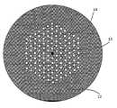
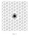
- FIG. 2shows microscope pictures of a preferred embodiment of a nonlinear microstructured optical fibre according to the present invention
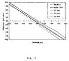
- FIG. 3shows dispersion properties of the fibre in FIG. 2 that has ZDW around 1.56 ⁇ m;
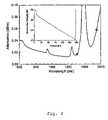
- FIG. 4shows the spectral attenuation of the fibre in FIG. 2 when spooled to a radius of 9 cm (solid line indicates white light measurements and the two points OTDR loss measurements. Inset shows OTDR trace at 1310 nm);
- FIG. 5shows a schematic example of another preferred embodiment of a fibre according to the present invention.
- FIG. 6shows a schematic example of a preferred embodiment of a polarization maintaining fibre according to the present invention
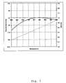
- FIG. 7shows dispersion and effective area properties of a fibre according to the present invention with flat, near-zero dispersion over about 100 nm around a wavelength of 1.55 ⁇ m;
- FIG. 8shows the mode field distribution of the fibre of FIG. 7 ;
- FIG. 9shows dispersion properties of a series of embodiments of fibres according to the present invention with variation of various design parameters
- FIG. 10shows effective area properties of a series of embodiments of fibres according to the present invention with variation of various design parameters
- FIG. 11shows dispersion properties of another series of embodiments of fibres according to the present invention with variation of various design parameters
- FIG. 12shows dispersion properties of a series of embodiments of fibres according to the present invention with variation of a single design parameter
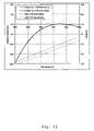
- FIG. 13shows dispersion and effective area properties of two different embodiments of fibres according to the present invention with flat, near-zero dispersion over about 100 nm around a wavelength of 1.55 ⁇ m;
- FIG. 14shows dispersion properties of two different embodiments of fibres with ZDW around 1064 nm
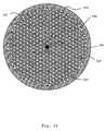
- FIG. 15shows a schematic example of a preform for producing a fibre according to the present invention.
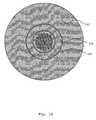
- FIG. 16shows a schematic example of a preform cane for producing a fibre according to the present invention.
- FIG. 1shows a schematic example of an embodiment of a fibre according to the present invention comprising a microstructured cladding with close-packed features 10 having a diameter, d, and a centre-to-centre spacing, ⁇ .
- the fibrecomprises further a core with a high index feature 11 having a higher refractive index than the background material of the cladding.
- the fibrefurther comprises a solid overcladding 12 .
- the solid overcladdingmainly serves to provide mechanical stability of the fibre and a given desired outer fibre diameter.
- another embodiment of a fibre according to the present inventionincludes further a coating—typically a polymer coating—for further mechanical stability of the fibre.
- the fibre in FIG. 1has d of around 0.8 ⁇ m and ⁇ of around 1.6 ⁇ m, and the number of periods or rings of cladding features surrounding the core is six, but higher numbers may be preferred in order to lower leakage or confinement losses.
- the fibre corecomprises a feature of maximum refractive index, n c , being around 2% higher than the refractive index of the cladding background material.
- FIG. 2shows microscope pictures of a fabricated fibre of an embodiment according to the present invention.
- the fibrehas a solid silica core region with a diameter of around 2.3 ⁇ m (the core diameter defined for the given design as 2 ⁇ -d).
- the core regioncomprises a high-index feature with a diameter of around 0.8 ⁇ m in diameter.
- the high-index featurenot visible in the pictures, has a parabolic index profile, but a broad range of other profiles are also covered by the present invention, and the maximum refractive index, n c , of the core feature is around 2% higher than the refractive index of pure silica.
- the microstructured claddingconsists of six periods of holes in a close-packed (also known as triangular) structure with an average hole-size of approximately 0.8 ⁇ m and an average or representative centre-to-centre spacing, ⁇ (or average pitch) of approximately 1.6 ⁇ m.
- Embodiments of optical fibre according to the present inventionmay be obtained using methods known in the art, such as described by DiGiovanni et al. in U.S. Pat. No. 5,802,236, or Broderick et al. in WO 02/14946.
- Embodiments of the present fibrewere produced in a step-wise process, where capillary tubes of approximately 2 mm in diameter were prepared and arranged in a periodic structure. A single, central capillary tube was replaced by a solid cane comprising a high-index region. The structure was placed in an overcladding tube to provide a preform and the preform was drawn to a cane with a diameter of around 3.6 mm using a conventional drawing tower operating at a temperature of around 1900° C.
- the canewas afterwards placed in a second overcladding tube and drawn into a second cane that again was overcladded and finally drawn to fibre using the same conventional drawing tower.
- the preformmay be prepared by controlled heat treatment, optionally under pressure and/or vacuum of the capillary tubes and the interstitial voids between the tubes.
- a skilled personwould know how to calibrate the parameters of the preparation, e.g. the temperature, pressure, vacuum, with respect to the glass of the capillaries applied, e.g. its thickness, viscosity, softness, etc., see e.g. the afore-mentioned references by DiGiovanni et al. or Broderick et al., the contents of which are incorporated herein by reference.
- the fabricated fibre shown in FIG. 2had a microstructured region being slightly elliptical (2.8%), resulting in an ellipticity of the core region.
- the ellipticitygives rise to a relatively strong birefringence that makes the fibre polarization maintaining.
- the birefringencehas been measured using a fixed analyzer technique yielding a birefringence, ⁇ n of approximately 1.1 ⁇ 10 ⁇ 4 at 1550 nm. This degree of birefringence is equivalent to a mean differential group delay of 0.37 ps/m or a beat length of 14 mm.
- embodiments of fibres according to the present inventionmay be spliced to standard optical fibres using commonly available splicing equipment.
- the fibre in FIG. 2was spliced with a loss of around 0.3 dB.
- the near fieldhas been measured at 1550 nm yielding an effective area of approximately 7 ⁇ m 2 . Consequently, the fibre is estimated to have a nonlinear coefficient of at least 20 (Wkm) ⁇ 1 , which is at least comparable to highly nonlinear fibres.
- Key data for the microstructured optical fibreis listed in table 1.
- the uniformity of the fibre structure in FIG. 2has been investigated by measuring pitch and core size along the three symmetry axis at four equally spaced positions in the fibre.
- the variation in pitch along the fibreis 2.4% and variation in core size is ⁇ 1.5%.
- the datais shown in table 2.
- FIG. 3shows four measurements of the dispersion of the fibre in FIG. 2 : a measurement on a 150 m master spool and three measurements on the rewinds in which the master spool has been divided for uniformity test.
- the measurementsshow good uniformity along the fibre as the ZDW is positioned within a 6 nm band for the three parts of the fibre, equivalent to a 0.4% variation. It is noted that the 2.4% structural non-uniformity only results in a 0.4% variation in ZDW indicating inherent robustness in the design.
- the dispersion slopeis in the range ⁇ 0.25 to ⁇ 0.27 ps/km/nm 2 at the ZDW.
- the negative slope of the fibreis especially interesting in combination with standard nonlinear fibres with positive dispersion slope, which enables creation of nonlinear devices with near-zero slope and low dispersion in a large wavelength range.
- FIG. 4shows measurements of the spectral attenuation in the fibre of FIG. 2 .
- the figureshows a low loss below 0.03 dB/m in the range from 700 nm to 1300 nm and a steep loss edge starting around 1500 nm. The position and slope of this loss edge is unaffected by spool radius and the present inventors have realized that the increase in loss around 1500 nm arises from increasing confinement losses. Loss measurements performed with OTDR at 1310 nm and 1550 nm yield losses of 0.017 dB/m and 0.058 dB/m respectively, which is consistent with the white-light measurements. To improve the fibre of FIG.
- more than five, such as more than six, such as more than seven periods of voids surrounding the coremay be preferred.
- the loss in the fibreis dominated by impurities and Si—OH absorption. Such losses may be lowered by improved quality of the material for the preform, by improved cleanness during preform assembling and handling, as well as during fibre drawing.
- FIG. 5Another embodiment of a fibre according to the present invention is shown in FIG. 5 .
- the fibrehas an improved design to allow for a reduce dispersion slope characteristics, i.e. the fibre may exhibit a zero or near zero dispersion over a broad range of wavelengths.
- the reduced slopeis obtained by raising the index around the core to a level higher than that for a fully periodic triangular structure with solid core.
- the reduced slopeis obtained by comprising—within a cross-section of the fibre—features or elements of a refractive index being lower than the core and preferably lower than the cladding background material, but higher than the material of the cladding holes.
- FIG. 5shows schematically a cross-section of an embodiment of a fibre 50 according to the present invention comprising a core 51 and a micro-structured cladding.
- the corecomprises a material with refractive index n c
- the claddingcomprises a number of low-index cladding features 52 with refractive index n 1 that are placed in a cladding background material 53 with refractive index n b .
- Immediately surrounding the core 51are placed one or more first inner cladding features 54 and one or more second inner cladding features 55 .
- the first inner cladding featureshave a refractive index similar to the low-index cladding features, namely n 1 .
- the second inner cladding secondary featureshave a refractive index n 2 .
- the fibreis characterized in that n 2 is lower than n c and n 2 is higher than n 1 .
- the fibre in FIG. 5may be seen as an improvement to the fibre in FIG. 1 , where a number of innermost holes around the core have been replaced by low-index glass features. In the example shown in FIG. 5 , three air holes have been replaced by low-index glass features around the core.
- the low-index cladding features 52 and the first inner cladding featureshave a substantially similar size.
- n 2is lower than n b .
- the first inner cladding featuresare made of silica or doped silica, such as F-doped silica.
- FIG. 6shows schematically an example of an embodiment of a fibre according to the present invention, where the number of second inner cladding features 61 is two.
- the fibrehas a substantially two-fold symmetry in the fibre cross-section in order to enhance birefringence.
- FIG. 7shows the results of calculating dispersion and effective area for a specific fibre with a design as shown schematically in FIG. 5 .
- the fibrehas a core 51 that is formed from a Ge-doped silica rod having n c of around 1.487, and a diameter of the doped part being equal to ⁇ , where ⁇ is the centre-to-centre distance between two low-index cladding features.
- the cladding background materialis pure silica with n b of around 1.444, and the second inner cladding features have n 2 of around 1.439.
- the first inner cladding features and the low-index cladding featuresare similar and comprise air or vacuum, and they have a diameter of around 0.5 ⁇ .
- the first inner cladding features and the low-index cladding featureshave a substantially similar size. This allows for example use of similar preform elements to be used for the realization of the inner and outer parts of the microstructured cladding. Also it is an advantage that holes of substantially similar size are used, since it may be more difficult to control hole sizes accurately during fibre fabrication if holes of different sizes are present. For example using pressure control during drawing of the fibre, it is an advantage that a similar pressure may be applied to all holes for embodiments of fibres according to the present invention.
- FIG. 8shows the field distribution of the fundamental mode of the fibre in FIG. 7 at a wavelength of 1.55 ⁇ m.
- the modeis confined to the core of the fibre and only has a limited amount of its energy distributed outside the core.
- FIG. 9shows the influence of core size and core doping level on the dispersion properties of a fibre with a design as shown schematically in FIG. 5 .
- the solid curveshows the dispersion for a fibre where a part of the core has been up-doped to provide a 2% refractive index increase compared to pure silica.
- the diameter of the doped part of the coreis 0.5 ⁇ .
- the fibrehas further n 2 equal to n b (no down-doping of the second inner cladding features; n 2 and n b being equal to the refractive index of pure silica that is around 1.444 at a wavelength of around 1.55 ⁇ m).
- the long-dashed curveshows the dispersion for a similar fibre as the fibre above, but with n 2 equal to 1.439, and the second inner cladding features having a diameter of ⁇ .
- the short-dashed curveshows dispersion for a fibre similar to the fibre of the long-dashed curve, but with a core being fully doped over its diameter, ⁇ .
- the dashed-dotted curveshows the dispersion of the same fibre as in FIG. 7 .
- This fibreis similar to the fibre of the short-dashed curve, but with a doped core having a refractive index being 3% higher than pure silica.
- the use of second inner cladding featuresprovides a reduced dispersion slope.
- FIG. 9the use of second inner cladding features provides a reduced dispersion slope.
- the dispersion characteristicsmay be tuned by tuning the refractive index profile of the core. Further means for tuning the dispersion characteristics include adjusting the number, size, separation, and position of the low-index cladding features, of the first inner cladding doping level, as well as of the second inner cladding features.
- FIG. 10shows the influence of core size and core doping level on the effective area of the same series of fibres as in FIG. 9 .
- the characteristics of the fibres for the four different curvesare described for FIG. 9 .
- FIG. 10shows that fibres according to the present invention provide relatively low effective areas—corresponding to relatively high nonlinear coefficients.
- FIGS. 9 and 10demonstrate that embodiments according to the present invention provides improved nonlinear optical fibres where it is possible to obtain a relatively high nonlinear coefficient and a high control over the dispersion and dispersion slope characteristics.
- the present inventionprovides an improved nonlinear fibre, having a small effective area (a high nonlinear coefficient) and a zero or near-zero dispersion wavelength around 1550 nm, as well as a flat dispersion (a reduced dispersion slope).
- Fibres according to the present inventionhave many degrees of freedom for tailoring their properties for a given application.
- FIG. 11shows the dispersion properties for a series of embodiments of fibres with a design a shown schematically in FIG. 5 and characteristics as for the fibre in FIG. 7 , but d/ ⁇ for the low-index cladding features varying from 0.44 to 0.56 and ⁇ varying from 1.24 ⁇ m to 1.61 ⁇ m.
- the dispersion slopemay be tailored from both negative, zero and positive values around 1550 nm by adjusting the above-mentioned parameters.
- FIG. 12shows the dispersion properties of the embodiment of a fibre shown in FIG. 7 , where ⁇ is varied from around 1.34 ⁇ m to around 1.40 ⁇ m.
- FIG. 13shows the effect on the dispersion and effective area of adjusting the refractive index of the second inner cladding features for the fibre of FIG. 7 .
- n 2is varied from 0.3% to 0.5% lower than pure silica.
- the dispersion propertiesare affected to a small degree, whereas the effective area is lowered for the decreased value of n 2 .
- Both fibreshave pure silica cladding background material.
- the use of second inner cladding featuresprovides means for reducing the dispersion slope. As previously discussed, such a property may be desired for a number of reasons, including, but not limited to, reduction of threshold power of non-linear effect and broader bandwidth of a nonlinear device.
- FIG. 15shows an exemplary preform for fabricating a fibre according to the present invention.
- the preformcomprises a rod 151 .
- This rodmay preferably be a silica rod doped with for example Ge having a diameter of a few millimeters (for example 3 mm).
- Such doped rodsmay be purchased from various commercial suppliers, e.g. FiberCore.
- Outside the core rodis placed a first ring of preform elements.
- These preform elementsinclude capillary tubes 152 and solid low-index rods 153 , that will provide the first and second inner cladding features in the final fibre.
- the capillary tubemay be purchased from various commercial suppliers, e.g.
- the low-index rodsare preferably F-doped silica that may also be purchased from various commercial suppliers, e.g. Hereaus or ShinEtsu.
- a number of capillary tubes 154that provides the outer part of the microstructured cladding. These capillary tubes are preferably identical to capillary tubes in the inner cladding.
- the preform elementsare placed in an overcladding tube 155 (available also from e.g. Hereaus) that provides mechanical support and holds together the preform.
- the preformmay further comprise various stuffing elements 156 to support the capillary tubes and aid in maintaining them in a desired position.
- the various elements of the preformmay be stacked in various arrangements to yield a desired structure—as would be known to a person skilled in the art. Also other manners of realizing the preform, for example using drilling of holes in glass rods, extrusion or sol-gel techniques may be preferred—as described in the prior art, see for example WO 00/06506 or EP 1 172 339. Further information on fabricating microstructured fibres may be found in U.S. Pat. No. 5,802,236 or WO 00/49436.
- the preform and the preform elementsmay optionally be fixed by inserting the preform into a lathe where the preform is heated to melt together all or part of the preform elements. Preferably, a pressure may be applied to the capillary tubes to maintain them open. Also, a less than atmospheric pressure may be applied between the preform elements in order to seal them together and collapse interstitial voids in the preform.
- the preform in FIG. 15may be drawn into a cane with a diameter of a few millimeters, for example 4 mm, using a conventional drawing tower that is operated at a temperature of around 1900 degrees Celsius.
- the pressure in the capillary tubeis controlled during drawing of the cane.
- the capillary tubesmay be closed at their top end to ensure that holes do not collapse.
- the capillary tubesare kept open and a less than atmospheric pressure is applied between the capillary tubes (inside the overcladding tube) to collapse to interstitial voids between the various preform elements.
- the size of the holes and the closure of interstitial voidsmay be controlled by adjusting the pulling and/or preform feeding speed, and temperature during drawing—as would be known to a person skilled in the art of producing microstructured fibres.
- the canemay be further overcladded as shown in FIG. 16 , where the preform cane 161 has been overcladding by two overcladding tubes 162 and 163 .
- This new preformmay be drawn into fibre using a similar conventional drawing tower.
- the pressure in the hole in the preform caneis controlled and/or adjusted during fibre drawing.
- a less than atmospheric pressureis applied between the preform cane and the overcladding tube as well as between the two overcladding tubes in order to seal together the preform cane and the two overcladding tubes.
- a single overcladding tube or more overclading tubesmay be used.
- the sealing of the preform cane and the overcladding tube(s)may be performed at a lathe prior to fibre drawing.
- the fibreis preferably drawn to an outer diameter of 125 ⁇ m and one or more layers of coating as known from standard optical fibre technology is applied.
Landscapes
- Physics & Mathematics (AREA)
- Chemical & Material Sciences (AREA)
- Optics & Photonics (AREA)
- General Physics & Mathematics (AREA)
- Dispersion Chemistry (AREA)
- Engineering & Computer Science (AREA)
- Nonlinear Science (AREA)
- Geochemistry & Mineralogy (AREA)
- Manufacturing & Machinery (AREA)
- Materials Engineering (AREA)
- Organic Chemistry (AREA)
- General Life Sciences & Earth Sciences (AREA)
- Life Sciences & Earth Sciences (AREA)
- Crystallography & Structural Chemistry (AREA)
- Optical Modulation, Optical Deflection, Nonlinear Optics, Optical Demodulation, Optical Logic Elements (AREA)
Abstract
Description
This is a nationalization of PCT/DK03/00178 filed Mar. 14, 2003 and published in English.
The present invention relates to a nonlinear optical fibre having a small core and special dispersion properties, a method of producing such a fibre, and use of such a fibre.
Nonlinear optical fibres with zero-dispersion wavelength (ZDW) around 1.5 μm are attractive for a range of telecom applications such as 2R regeneration, multiple clock recovery, optical parametric amplifiers (OPAs), pulse compression, soliton generation, wavelength conversion, alloptical switching and supercontinuum-based wavelength demultiplexed (WDM) telecom sources (see for example Petropoulos et al.,Optical Fiber Communication Conference,2001; Futami et al.,European Conference on Optical Communications,2000; Hansryd et al.,Photonics Technology Letters13(3), pp. 194-196, 2001; Sharping et al., IEEE Photonics Technology Letters, Vol. 14 Issue. 1, pp. 7-79, 2002; or Takushima et al.,Photonics Technology Letters11(3), pp. 322-324, 1999).
In the prior art, nonlinear optical fibres with ZDW around 1.5 μm have been based on standard optical fibre technology, where a solid high-index core is surrounded by a solid cladding having a lower refractive index than the core (see for example U.S. Pat. No. 6,347,174). Typically prior art nonlinear fibres with ZDW around 1.5 μm have a nonlinear coefficient of approximately 10 (Wkm)−1. For applications such as e.g. OPAs, nonlinear coefficients of this order demands fibre lengths on the order of hundreds of meters.
Within the past five years, a new type of optical fibre has emerged. This type of fibre employs microstructured features running along the fibre axis, and is referred to by several names, e.g. microstructured fibres, photonic crystal fibres (PCF), holey fibres, or hole-assisted fibres.
Typically the microstructured features are voids (such as for example air holes) and the voids may provide this fibre type several advantages compared to standard technology nonlinear fibres. The high index difference between the silica core and air-filled microstructure features enables tight mode confinement to the fibre core—thereby resulting in a small effective area and consequently a high nonlinear coefficient. In addition, the ability of the cladding structure to be tailored enables high flexibility in the design of the dispersion profile (see for example Ferrando et al.,Optics Express9(13), pp. 687-697, 2001; Monro et al.Journal of Lightwave Technology, Vol. 17, No. 6, pp. 1093-1102, 1999; or WO 0212931). This flexibility facilitates generation of different nonlinear effects, especially by the choice of zero-dispersion wavelength (ZDW).
In particular, microstructured fibres may be realized with very small cores (smaller than 3 μm in diameter) and ZDW at relatively short wavelengths (shorter than 1.3 μm). Such nonlinear microstructured fibres have received a significant interest (see for example U.S. Pat. No. 6,097,870) and a much studied area of these fibres is super continuum generation with pumping wavelength around 600-800 nm (see for example Ranka et al., Optics Letters 25[1], pp. 25-27, 2000; Coen et al.Optics Letters26(17), pp. 1356-1358, 2001., or Hansen et al.,LEOS Conference2001, 2001. A number of potential applications exist of super continual including optical coherence tomography, spectroscopy, and meteorology.
While nonlinear microstructured fibres with ZDW shorter than 1.3 μm have been extensively studied, prior art microstructured fibres with ZDW around 1.5 μm have only been addressed in theoretical works—see for example Ferrando et al.,Optics Express9(13), pp. 687-697, 2001; Monro et al.Journal of Lightwave Technology, Vol. 17, No. 6, pp. 1093-1102, 1999; or WO 02/12931. The fibres disclosed by Ferrando et al. and Monro et al. with ZDW around 1.5 μm have a microstructured cladding comprising close-packed air holes with a diameter, d, of around 0.3 times a centre-to-centre spacing, Λ. The fibres are further characterized by a solid, pure silica core with a diameter of around 3.9 μm or larger (the core diameter being approximately equal to 2Λ-d).
White et al. inOptics Letters26(21), pp. 1660-1662, 2001 disclose a microstructured fibres with large air holes in order to reduce confinement losses. Nothing is indicated nor suggested about tailoring of dispersion properties, in particular to provide ZDW around 1.5 μm. Further nothing is disclosed about a flat dispersion slope.
Barkou et al., WO 02/12931, disclose a nonlinear microstructured optical fibre having an inner cladding and an outer cladding wherein the inner cladding holes are smaller than the outer cladding holes. Nothing is indicated nor suggested about providing an optical fibre with a non-partitioned cladding with substantially equal sized cladding features.
Generally, it is desired to provide ZDW or near-zero dispersion over an extended wavelength range. Hence, it is generally desired to be able to control not only the dispersion at a given wavelength, but also the dispersion slope of nonlinear optical fibre. The dispersion slope is the derivative of the dispersion with respect to wavelength and, thereby, control of the dispersion slope provides control of the dispersion over a broad wavelength range. This facilitates broadband applications, for example continuum generation over broad wavelength ranges and nonlinear processes, where a pump and signal light are broadly separated. Depending on the specific application, the broadness in terms of wavelength range may be a few nanometres or it may be several hundreds and even more than a thousand nanometres.
Another important area of applications of nonlinear optical fibres includes Raman amplification (see for example Agrawal, “Nonlinear fiber optics”, Third Ed., Academic Press; Yusoff et al. Optics Letters, Vol. 27, No. 6, 2002). In optical communications, Raman fibre amplifiers are use for both discrete amplification and distributed amplification. In the former case the nonlinear fibre is inserted as an component at one or more discrete site of an optical communication link, whereas in the latter case the nonlinear fibre constitute a part of the transmission link in an optical communication system. Especially, for use of nonlinear optical fibre in optical communications, it is important to control the dispersion and often also the dispersion slope of the nonlinear optical fibre. Hence, in order to control for the development of nonlinear fibres for optical communication systems, there are three important parameters: the nonlinear coefficient, the dispersion, and the dispersion slope. An important use of nonlinear optical fibre in optical communication systems is as Raman amplifier that at the same time provides dispersion and/or dispersion slope compensation (see for example Gnauck et al. Optical Fiber Communication Conference, post deadline paper FC-2, 2002, where dispersion compensating modules are also used for Raman amplification). Hence, it is desired to provide nonlinear fibres with dispersion and/or dispersion slope compensating characteristics that at the same time has a high nonlinear coefficient in order to allow for Raman amplification.
Object of the Invention
It is an object of the present invention to provide new fibre designs of nonlinear fibres, where the nonlinear coefficient, the dispersion and the dispersion slope may be tailored more freely than for prior art nonlinear fibres.
It is a further object of the present invention to provide new designs of nonlinear optical fibres, where the dispersion and the dispersion slope may be tailored precisely, while a high nonlinear coefficient is simultaneously obtained.
It is, therefore, an object of the present invention to provide nonlinear microstructured optical fibres with ZDW around 1.5 μm for hole sizes larger than d/Λ=0.3.
Further objects appear from the description elsewhere.
Solution According to the Invention
In a first aspect, the present invention relates to an optical fibre having a longitudinal direction and a cross-section perpendicular thereto, said fibre in a cross-section comprising:
- (a) a core region having a refractive index profile with a highest refractive index nc, and
- (b) a cladding region comprising cladding features having a centre-to-centre spacing, Λ, and a diameter, d, of around 0.4Λ or larger,
- wherein nc, Λ and d are adapted such that the fibre exhibits zero dispersion wavelength of a fundamental mode in the wavelength range from 1530 nm to 1640 nm;
- whereby fibre designs with a relatively high nonlinear coefficient can be obtained.
In a preferred embodiment, the microstructured optical fibre comprises a glass background material in the cladding and/or in the core, such as a silica-based glass or a compound glass. Glass materials are preferred in order to a provide low-loss background material of the fibres, as well as a material that may be handled using presently known techniques for fabricating microstructured optical fibres.
In a further preferred embodiment, the cladding features are voids, such as holes filled with air, another gas, or a vacuum. Such features are preferred in order to utilize a high refractive index contrast to the fibre background material, as this provides flexibility for tailoring dispersion characteristics of the fibre as well as provide small effective mode field diameters.
In a further preferred embodiment, the microstructured optical fibre comprises a background material in the cladding with a refractive index in the range from 1.43 to 1.47, such as around 1.444. Such refractive index ranges are feasible using silica based materials, including pure, fused silica and silica doped with various materials, such as for example Ge, F, Al, P, Sn, B, La or combinations of these.
In a further preferred embodiment, ncis in the range of around 1.444 to 1.49, such as around 1.47. The core regions is preferred to have a higher refractive index than the background material of the cladding, and low-loss glass may be fabricated using silica technology with refractive indices of up to at least 1.49.
Compound glasses (such as for example chalcogonide glasses) may be preferred due to higher intrinsic nonlinearindex coefficient than silica-based glasses. Furthermore, for compound glasses the refractive index may be varied more freely than for silica glasses and therefore in preferred embodiments, the nonlinear microstructured optical fibre comprises compound glasses.
In a further preferred embodiment, the microstructured optical fibre comprises at least five rings or periods of cladding features surrounding the core, such as at least six rings or periods of cladding features surrounding the core, such as at least seven rings or periods of cladding features surrounding the core in order to reduce leakage losses and provide low loss transmission in the fibre.
In a further preferred embodiment, a majority of the cladding features being substantially equal in size. During fabrication it is often preferred to have voids of similar holes, and in order to provide ZDW around 1.5 mm, it is preferred that at least the three innermost rings of voids are substantially equal in size. Preferably, more rings surrounding the core have equally sized holes, such as at least four, five or more rings. A person skilled in the art will recognise that minor differences in size may results from the fabrication process. Typically such variations are less than a few percent.
In a further preferred embodiment, the microstructured optical fibre comprises cladding features with diameters of around 0.8 μm, such as in the range from 0.7 μm to 0.9 μm.
In a further preferred embodiment, the microstructured optical fibre comprises cladding features with centre-to-centre spacing, Λ, of around 1.6 μm, such as in the range from 1.2 μm to 1.8 μm.
In a further preferred embodiment, the core region has a core diameter, dc, being defined as 2Λ-d, and this core diameter is in the range of 1.5 μm to 3.0 μm. In particular it is preferred that the core diameter is in the range of 2.2 μm to 2.5 μm.
In a further preferred embodiment, the core region comprises a core feature having a diameter, dc,feat, being smaller than or equal to dc. The core feature takes part in defining the refractive index profile of the core region, and the maximum refractive index of the core feature is identical to the maximum refractive index of the core region.
In a further preferred embodiment, the core feature has a diameter, dc,feat, in the range of 0.2 dcto 0.9 dc, such as in the range of 0.4 dcto 0.7 dc, such as in the range of 0.45 dcto 0.55 dc, such as around 0.50 dc.
Other aspects and preferred embodiments appear elsewhere in the application.
It is to be understood that the following detailed description and accompanying drawings further describe principles and operation of exemplary embodiments of the invention, and that the invention is not intended to be limited thereto.
In the following, by way of examples only, the invention is further disclosed with detailed description of preferred embodiments. Reference is made to the drawings in which
The fibre inFIG. 1 has d of around 0.8 μm and Λ of around 1.6 μm, and the number of periods or rings of cladding features surrounding the core is six, but higher numbers may be preferred in order to lower leakage or confinement losses. The fibre core comprises a feature of maximum refractive index, nc, being around 2% higher than the refractive index of the cladding background material.
It turns out that the high-index feature in the core region provides increased nonlinear refractive index of the core, as well as it provides a smaller mode field diameter, and furthermore it aids to reduce confinement loss. The microstructured cladding consists of six periods of holes in a close-packed (also known as triangular) structure with an average hole-size of approximately 0.8 μm and an average or representative centre-to-centre spacing, Λ (or average pitch) of approximately 1.6 μm.
Embodiments of optical fibre according to the present invention may be obtained using methods known in the art, such as described by DiGiovanni et al. in U.S. Pat. No. 5,802,236, or Broderick et al. in WO 02/14946. Embodiments of the present fibre were produced in a step-wise process, where capillary tubes of approximately 2 mm in diameter were prepared and arranged in a periodic structure. A single, central capillary tube was replaced by a solid cane comprising a high-index region. The structure was placed in an overcladding tube to provide a preform and the preform was drawn to a cane with a diameter of around 3.6 mm using a conventional drawing tower operating at a temperature of around 1900° C. The cane was afterwards placed in a second overcladding tube and drawn into a second cane that again was overcladded and finally drawn to fibre using the same conventional drawing tower. The preform may be prepared by controlled heat treatment, optionally under pressure and/or vacuum of the capillary tubes and the interstitial voids between the tubes. A skilled person would know how to calibrate the parameters of the preparation, e.g. the temperature, pressure, vacuum, with respect to the glass of the capillaries applied, e.g. its thickness, viscosity, softness, etc., see e.g. the afore-mentioned references by DiGiovanni et al. or Broderick et al., the contents of which are incorporated herein by reference.
The fabricated fibre shown inFIG. 2 had a microstructured region being slightly elliptical (2.8%), resulting in an ellipticity of the core region. The ellipticity gives rise to a relatively strong birefringence that makes the fibre polarization maintaining. The birefringence has been measured using a fixed analyzer technique yielding a birefringence, Δn of approximately 1.1·10−4at 1550 nm. This degree of birefringence is equivalent to a mean differential group delay of 0.37 ps/m or a beat length of 14 mm.
Despite a small core size and an air-filled microstructured region, embodiments of fibres according to the present invention may be spliced to standard optical fibres using commonly available splicing equipment. Using a commercially available optical fibre with an ultra high NA, the fibre inFIG. 2 was spliced with a loss of around 0.3 dB.
In order to estimate the nonlinear coefficient of the fibre inFIG. 2 , the near field has been measured at 1550 nm yielding an effective area of approximately 7 μm2. Consequently, the fibre is estimated to have a nonlinear coefficient of at least 20 (Wkm)−1, which is at least comparable to highly nonlinear fibres. Key data for the microstructured optical fibre is listed in table 1.
| Average pitch: | 1.6 μm | ||
| Average hole diameter: | 0.8 μm | ||
| Core diameter: | 2.3 μm | ||
| Fibre diameter: | 126 μm | ||
| Splice loss: | 0.3 dB | ||
| Numerical aperture: | ~0.5 | ||
| Birefringence: | 1.1 · 10−4 | ||
| Nonlinear coefficient: | ~20 (Wkm)−1 | ||
The uniformity of the fibre structure inFIG. 2 has been investigated by measuring pitch and core size along the three symmetry axis at four equally spaced positions in the fibre. The variation in pitch along the fibre is 2.4% and variation in core size is <1.5%. The data is shown in table 2.
| Position | Average pitch | Average core size |
| [m] | [μm] | [μm] |
| 0 | 1.62 | 2.3 |
| 50 | 1.59 | 2.3 |
| 100 | 1.62 | 2.3 |
| 150 | 1.63 | 2.4 |
Another embodiment of a fibre according to the present invention is shown inFIG. 5 . The fibre has an improved design to allow for a reduce dispersion slope characteristics, i.e. the fibre may exhibit a zero or near zero dispersion over a broad range of wavelengths. The reduced slope is obtained by raising the index around the core to a level higher than that for a fully periodic triangular structure with solid core. In contrast to the designs disclosed by Barkou et al. in WO 02/12931, the reduced slope is obtained by comprising—within a cross-section of the fibre—features or elements of a refractive index being lower than the core and preferably lower than the cladding background material, but higher than the material of the cladding holes. Alternatively, the design may be seen as being realized by a number of air holes around the core being replaced with down-doped glass features or elements, areas. Hence,FIG. 5 shows schematically a cross-section of an embodiment of afibre 50 according to the present invention comprising acore 51 and a micro-structured cladding. The core comprises a material with refractive index nc, and the cladding comprises a number of low-index cladding features52 with refractive index n1that are placed in acladding background material 53 with refractive index nb. Immediately surrounding the core51 are placed one or more first inner cladding features54 and one or more second inner cladding features55. The first inner cladding features have a refractive index similar to the low-index cladding features, namely n1. The second inner cladding secondary features have a refractive index n2. The fibre is characterized in that n2is lower than ncand n2is higher than n1.
Alternatively, the fibre inFIG. 5 may be seen as an improvement to the fibre inFIG. 1 , where a number of innermost holes around the core have been replaced by low-index glass features. In the example shown inFIG. 5 , three air holes have been replaced by low-index glass features around the core.
In a preferred embodiment, the low-index cladding features52 and the first inner cladding features have a substantially similar size.
In another preferred embodiment n2is lower than nb.
In a further preferred embodiment, the first inner cladding features are made of silica or doped silica, such as F-doped silica.
The here-disclosed design ideas may also be used to provide polarization maintaining nonlinear optical fibre.FIG. 6 shows schematically an example of an embodiment of a fibre according to the present invention, where the number of second inner cladding features61 is two. The fibre has a substantially two-fold symmetry in the fibre cross-section in order to enhance birefringence.
From a fabrication point of view, it is an advantage that the first inner cladding features and the low-index cladding features have a substantially similar size. This allows for example use of similar preform elements to be used for the realization of the inner and outer parts of the microstructured cladding. Also it is an advantage that holes of substantially similar size are used, since it may be more difficult to control hole sizes accurately during fibre fabrication if holes of different sizes are present. For example using pressure control during drawing of the fibre, it is an advantage that a similar pressure may be applied to all holes for embodiments of fibres according to the present invention.
Fibres according to the present invention have many degrees of freedom for tailoring their properties for a given application. As an example of the flexibility in tailoring the dispersion slope of a fibre with ZDW around 1550 nm,FIG. 11 shows the dispersion properties for a series of embodiments of fibres with a design a shown schematically inFIG. 5 and characteristics as for the fibre inFIG. 7 , but d/Λ for the low-index cladding features varying from 0.44 to 0.56 and Λ varying from 1.24 μm to 1.61 μm. As seen from the figure, the dispersion slope may be tailored from both negative, zero and positive values around 1550 nm by adjusting the above-mentioned parameters.
To further demonstrate the flexibility for fibres according to the present invention,FIG. 12 shows the dispersion properties of the embodiment of a fibre shown inFIG. 7 , where Λ is varied from around 1.34 μm to around 1.40 μm.FIG. 13 shows the effect on the dispersion and effective area of adjusting the refractive index of the second inner cladding features for the fibre ofFIG. 7 . InFIG. 13 , n2is varied from 0.3% to 0.5% lower than pure silica. As seen fromFIG. 13 , the dispersion properties are affected to a small degree, whereas the effective area is lowered for the decreased value of n2.
Optical fibres according to the present invention are also of interest for applications at other wavelengths than around 1.3 μm to 1.7 μm, such as for applications at visible wavelengths and short near-infrared wavelengths—such as wavelengths from 400 nm to 1.3 μm, in particular for application at wavelengths around 800 nm and around 1064 nm. As an example,FIG. 14 demonstrates how the dispersion slope may be decreased for a nonlinear fibre with ZDW around 1.06 μm using a design as schematically shown inFIG. 5 (solid curve) as compared to a fibre with a design as schematically shown inFIG. 1 (dashed curve). The dashed curve is for a fibre comprising a doped core with nc=1.472, and cladding holes having d=0.53Λ and Λ=2.05 μm, whereas the solid curve shows the dispersion for a fibre comprising a doped core with nc=1.472, second inner cladding features with n2=1.440, and low-index cladding features having diameter 0.5Λ and Λ=1.2 μm, and first inner cladding features of similar size as the low-index cladding features. Both fibres have pure silica cladding background material. As seen fromFIG. 14 , the use of second inner cladding features provides means for reducing the dispersion slope. As previously discussed, such a property may be desired for a number of reasons, including, but not limited to, reduction of threshold power of non-linear effect and broader bandwidth of a nonlinear device.
The preform inFIG. 15 may be drawn into a cane with a diameter of a few millimeters, for example 4 mm, using a conventional drawing tower that is operated at a temperature of around 1900 degrees Celsius. Preferably the pressure in the capillary tube is controlled during drawing of the cane. Alternatively, the capillary tubes may be closed at their top end to ensure that holes do not collapse. Alternatively, the capillary tubes are kept open and a less than atmospheric pressure is applied between the capillary tubes (inside the overcladding tube) to collapse to interstitial voids between the various preform elements. The size of the holes and the closure of interstitial voids may be controlled by adjusting the pulling and/or preform feeding speed, and temperature during drawing—as would be known to a person skilled in the art of producing microstructured fibres. After fabrication of the preform cane, the cane may be further overcladded as shown inFIG. 16 , where thepreform cane 161 has been overcladding by twoovercladding tubes
Claims (36)
1. An optical fibre for transmitting light of at least one predetermined wavelength λ, the optical fibre having a longitudinal direction and a cross-section perpendicular thereto, the optical fibre comprising:
(a) a core region comprising a core material of refractive index nc; and
(b) a cladding region, said cladding region surrounding said core region and comprising low-index cladding features of refractive index n1arranged in a background cladding material of refractive index nb;
said cladding region further comprising first inner cladding features of refractive index n1and second inner cladding features of refractive index n2, where n2is lower than nc, and n2is higher than n1, and
said first inner cladding features and said second inner cladding features are arranged proximal to said core region, and
n2is lower than nb.
2. The optical fibre according toclaim 1 , wherein a number or all of said low-index cladding features have a diameter d1,outerand a centre-to-centre spacing Λ1,outer, and d1,outeris around 0.4Λ1,outeror larger.
3. The optical fibre according toclaim 1 , wherein a number or all of said first inner cladding features have a diameter d1,innerand a centre-to-centre spacing Λ1,innerand d1,inneris around 0.4Λ1,inneror larger.
4. The optical fibre according toclaim 2 , wherein a number or all of said first inner cladding features have a diameter d1,inner, and d1,inneris around 0.4Λ1,outeror larger.
5. The optical fibre according to theclaim 2 , wherein d1,outeris in the range of 0.4Λ1,outerto 0.60Λ1,outer.
6. The optical fibre according toclaim 4 , wherein d1,inneris in the range of 0.4Λ1,outerto 0.60Λ1,outer.
7. The optical fibre according toclaim 2 , wherein a plurality or all of said first inner cladding features have a diameter d1,innerand wherein d1,outer, and d1,innerare substantially similar.
8. The optical fibre according toclaim 2 , wherein a plurality or all of said first inner cladding features have a centre-to-centre spacing Λ1,innerand wherein Λ1,outerand/or Λ1,inneris in the range of 1.0 μm to 2.0 μm.
9. The optical fibre according toclaim 2 , wherein a plurality or all of said first inner cladding features have a diameter d1,innerand wherein d1,outerand/or d1,inneris in the range of 0.4 μm to 1.2 μm.
10. The optical fibre according toclaim 1 , wherein said core region comprises silica and/or silica doped with a material to provide an increase of refractive index compared to pure silica.
11. The optical fibre according toclaim 2 , wherein ncis about or more than 1% higher than the refractive index of pure silica.
12. The optical fibre according toclaim 1 , wherein ncis larger than 1.444.
13. The optical fibre according toclaim 1 , wherein said first inner cladding features comprise silica or silica doped with a material to provide a decrease of refractive index compared to pure silica.
14. The optical fibre according toclaim 2 , wherein n2is about or more than 0.1% lower than the refractive index of pure silica.
15. The optical fibre according toclaim 1 , wherein n2is lower than 1.444.
16. The optical fibre according toclaim 1 , wherein said low-index cladding features and said first inner cladding features are voids.
17. The optical fibre according toclaim 1 , wherein said optical fibre comprises at least five rings or periods of low-index cladding features surrounding the core.
18. The optical fibre according toclaim 1 , wherein a majority of said low-index cladding features are substantially equal in size.
19. The optical fibre according toclaim 1 , wherein said low-index cladding features within a distance of at least three periods from the core are sub-stantially equal in size.
20. The optical fibre according toclaim 1 , wherein said core region comprises a core feature having a diameter, dc,feat, said core feature having a refractive index profile with a maximum refractive index being equal to nc.
21. The optical fibre according toclaim 2 , wherein said core region comprises a core feature having a diameter, dc,feat, and wherein dc,featis in the range of 0.2Λ1,outerto 1.0Λ1,outer.
22. The optical fibre according toclaim 1 , wherein said optical fibre comprises a limited number of second inner cladding features, said limited number being equal to two or three.
23. The optical fibre according toclaim 1 , wherein said predetermined wavelength λ is in the range of 1.3 μm to 1.7 μm.
24. The optical fibre according toclaim 1 , wherein said predetermined wavelength λ is in the range of 0.6 μm to 1.0 μm.
25. The optical fibre according toclaim 1 , wherein said predetermined wavelength λ is in the range of 1.0 μm to 1.3 μm.
26. A method of producing a microstructured optical fibre, the method comprising:
(a) providing a preform by providing and arranging preform elements in a predetermined structure:
at least one high-index rod to form a core region of the preform,
and surrounding said high-index rod by first elements of capillary tubes and low-index rods to form an inner cladding region proximal to said at least one high-index rod, said capillary tubes and low-index rods providing first and second inner cladding features in a final fibre, and
surrounding said at least one high-index rod, said first elements of capillary tubes and said low-index rods by outer elements of capillary tubes providing an outer part of the micro-structured cladding; and
(b) consolidating said structure; and
(c) drawing said preform to an optical fibre with pre-determined dimension under a controlled heat treatment.
27. A method of guiding electromagnetic waves comprising providing an optical fibre with a core region comprising a core material of refractive index ncand a cladding region, said cladding region surrounding said core region and comprising low-index cladding features of refractive index n1arranged in a background cladding material of refractive index nb, said cladding region further comprising first inner cladding features of refractive index n1and second inner cladding features of refractive index n2, where n2is lower than nc, and n2is higher than n1, and said first inner cladding features and said second inner cladding features being arranged proximal to said core region, and with n2being lower than nb; and feeding said optical fibre with electromagnetic waves having wavelength from 400 nm to 1.7 μm.
28. An article comprising an optical fibre for transmitting light of at least one predetermined wavelength λ, the optical fibre having a longitudinal direction and a cross-section perpendicular thereto, the optical fibre comprising:
(a) a core region comprising a core material of refractive index nc; and
(b) a cladding region surrounding said core region and comprising low-index cladding features of refractive index n1arranged in a background cladding material of refractive index nb,
said cladding region further comprising first inner cladding features of refractive index n1and second inner cladding features of refractive index n2, wherein n2is lower than nc, and n2is higher than n1,
said first inner cladding features and said second inner cladding features being arranged proximal to said core region, and
n2being lower than nb.
29. The article according toclaim 28 , wherein said article is a coated optical fibre or a cabled optical fibre.
30. The article according toclaim 28 , wherein said article is a nonlinear device.
31. The article according toclaim 28 , wherein said article is an optical communication system, an optical fibre laser, an optical fibre amplifier, an optical fibre Raman amplifier, a dispersion compensator, a dispersion and/or dispersion slope compensator, a combined dispersion compensator and Raman amplifier, a combined dispersion slope compensator and Raman amplifier, a combined dispersion and dispersion slope compensator and Raman amplifier, or a super-continuum generator.
32. The method as defined inclaim 26 , further comprising using said optical fibre to guide electromagnetic waves by incorporating said optical fibre into an article selected from the group consisting of an optical communication system, an optical fibre laser, an optical fibre amplifier, an optical fibre Raman amplifier, a dispersion compensator, a dispersion and/or dispersion slope compensator, a combined dispersion compensator and Raman amplifier, a combined dispersion slope compensator and Raman amplifier, a combined dispersion and dispersion slope compensator and Raman amplifier, and a super-continuum generator; and feeding said optical fibre with electromagnetic waves having wavelength from 400 nm to 1.7 μm.
33. A method of producing a microstructured optical fibre, the method comprising:
providing a preform by providing and arranging preform elements in a predetermined structure:
at least one high-index rod to form a core region of the preform,
and surrounding said high-index rod by first elements of capillary tubes and low-index rods to form an inner cladding region proximal to said at least one high-index rod, said capillary tubes and low-index rods providing first and second inner cladding features in a final fibre, and
surrounding said at least one high-index rod, said first elements of capillary tubes and said low-index rods by outer elements of capillary tubes providing an outer part of the micro-structured cladding; and
drawing said preform to a preform cane with predetermined dimension under a controlled heat treatment, followed by drawing said preform cane to an optical fibre with predetermined dimension under a controlled heat treatment.
34. A method of producing a microstructured optical fibre, the method comprising:
providing a preform by providing and arranging preform elements in a predetermined structure:
at least one high-index rod to form a core region of the preform,
and surrounding said high-index rod by first elements of capillary tubes and low-index rods to form an inner cladding region proximal to said at least one high-index rod, said capillary tubes and low-index rods providing first and second inner cladding features in a final fibre, and
surrounding said at least one high-index rod, said first elements of capillary tubes and said low-index rods by outer elements of capillary tubes providing an outer part of the micro-structured cladding; and
drawing said preform to an optical fibre with predetermined dimension under a controlled heat treatment.
35. The optical fibre according toclaim 1 , wherein said optical fibre comprises at least seven rings or periods of low-index cladding features surrounding the core.
36. The optical fibre according toclaim 1 , wherein said low-index cladding features within a distance of at least five periods from the core are substantially equal in size.
Priority Applications (1)
| Application Number | Priority Date | Filing Date | Title |
|---|---|---|---|
| US10/507,723US7266275B2 (en) | 2002-03-15 | 2003-03-14 | Nonlinear optical fibre method of its production and use thereof |
Applications Claiming Priority (5)
| Application Number | Priority Date | Filing Date | Title |
|---|---|---|---|
| US36411902P | 2002-03-15 | 2002-03-15 | |
| DKPA200201412 | 2002-09-24 | ||
| DKPA200201412 | 2002-09-24 | ||
| US10/507,723US7266275B2 (en) | 2002-03-15 | 2003-03-14 | Nonlinear optical fibre method of its production and use thereof |
| PCT/DK2003/000178WO2003079074A1 (en) | 2002-03-15 | 2003-03-14 | Improved nonlinear optical fibre method of its production and use thereof |
Publications (2)
| Publication Number | Publication Date |
|---|---|
| US20050238307A1 US20050238307A1 (en) | 2005-10-27 |
| US7266275B2true US7266275B2 (en) | 2007-09-04 |
Family
ID=28043200
Family Applications (1)
| Application Number | Title | Priority Date | Filing Date |
|---|---|---|---|
| US10/507,723Expired - Fee RelatedUS7266275B2 (en) | 2002-03-15 | 2003-03-14 | Nonlinear optical fibre method of its production and use thereof |
Country Status (3)
| Country | Link |
|---|---|
| US (1) | US7266275B2 (en) |
| AU (1) | AU2003226890A1 (en) |
| WO (1) | WO2003079074A1 (en) |
Cited By (170)
| Publication number | Priority date | Publication date | Assignee | Title |
|---|---|---|---|---|
| US20060263024A1 (en)* | 2005-05-20 | 2006-11-23 | Liang Dong | Single mode propagation in fibers and rods with large leakage channels |
| US20080056656A1 (en)* | 2004-01-16 | 2008-03-06 | Liang Dong | Large core holey fibers |
| US20080226242A1 (en)* | 2004-01-23 | 2008-09-18 | Koheras A/S | Method of Generating Supercontinuum Optical Radiation, Supercontinuum Optical Radiation Source, and Use Thereof |
| US20090122308A1 (en)* | 2004-12-30 | 2009-05-14 | Liang Dong | Photonic bandgap fibers |
| US20090245729A1 (en)* | 2008-03-26 | 2009-10-01 | Imra America, Inc. | Ultra small core fiber with dispersion tailoring |
| US20100157418A1 (en)* | 2007-09-26 | 2010-06-24 | Imra America, Inc. | Glass large-core optical fibers |
| US20110194812A1 (en)* | 2009-08-14 | 2011-08-11 | Gilles Melin | Microstructured optical fiber and a device for generating broadband white light |
| US20120257270A1 (en)* | 2011-04-11 | 2012-10-11 | The Regents Of The University Of California | Systems and methods for fiber optic parametric amplification and nonlinear optical fiber for use therein |
| US20140036527A1 (en)* | 2011-04-04 | 2014-02-06 | Danmarks Tekniske Universitet-Dtu | Light distribution system comprising spectral conversion means |
| US9119127B1 (en) | 2012-12-05 | 2015-08-25 | At&T Intellectual Property I, Lp | Backhaul link for distributed antenna system |
| US9154966B2 (en) | 2013-11-06 | 2015-10-06 | At&T Intellectual Property I, Lp | Surface-wave communications and methods thereof |
| US9209902B2 (en) | 2013-12-10 | 2015-12-08 | At&T Intellectual Property I, L.P. | Quasi-optical coupler |
| US9312919B1 (en) | 2014-10-21 | 2016-04-12 | At&T Intellectual Property I, Lp | Transmission device with impairment compensation and methods for use therewith |
| US9461706B1 (en) | 2015-07-31 | 2016-10-04 | At&T Intellectual Property I, Lp | Method and apparatus for exchanging communication signals |
| US9490869B1 (en) | 2015-05-14 | 2016-11-08 | At&T Intellectual Property I, L.P. | Transmission medium having multiple cores and methods for use therewith |
| US9503189B2 (en) | 2014-10-10 | 2016-11-22 | At&T Intellectual Property I, L.P. | Method and apparatus for arranging communication sessions in a communication system |
| US9509415B1 (en) | 2015-06-25 | 2016-11-29 | At&T Intellectual Property I, L.P. | Methods and apparatus for inducing a fundamental wave mode on a transmission medium |
| US9520945B2 (en) | 2014-10-21 | 2016-12-13 | At&T Intellectual Property I, L.P. | Apparatus for providing communication services and methods thereof |
| US9525210B2 (en) | 2014-10-21 | 2016-12-20 | At&T Intellectual Property I, L.P. | Guided-wave transmission device with non-fundamental mode propagation and methods for use therewith |
| US9525524B2 (en) | 2013-05-31 | 2016-12-20 | At&T Intellectual Property I, L.P. | Remote distributed antenna system |
| US9531427B2 (en) | 2014-11-20 | 2016-12-27 | At&T Intellectual Property I, L.P. | Transmission device with mode division multiplexing and methods for use therewith |
| US9564947B2 (en) | 2014-10-21 | 2017-02-07 | At&T Intellectual Property I, L.P. | Guided-wave transmission device with diversity and methods for use therewith |
| US9577306B2 (en) | 2014-10-21 | 2017-02-21 | At&T Intellectual Property I, L.P. | Guided-wave transmission device and methods for use therewith |
| US9608740B2 (en) | 2015-07-15 | 2017-03-28 | At&T Intellectual Property I, L.P. | Method and apparatus for launching a wave mode that mitigates interference |
| US9608692B2 (en) | 2015-06-11 | 2017-03-28 | At&T Intellectual Property I, L.P. | Repeater and methods for use therewith |
| US9615269B2 (en) | 2014-10-02 | 2017-04-04 | At&T Intellectual Property I, L.P. | Method and apparatus that provides fault tolerance in a communication network |
| US9628854B2 (en) | 2014-09-29 | 2017-04-18 | At&T Intellectual Property I, L.P. | Method and apparatus for distributing content in a communication network |
| US9628116B2 (en) | 2015-07-14 | 2017-04-18 | At&T Intellectual Property I, L.P. | Apparatus and methods for transmitting wireless signals |
| US9640850B2 (en) | 2015-06-25 | 2017-05-02 | At&T Intellectual Property I, L.P. | Methods and apparatus for inducing a non-fundamental wave mode on a transmission medium |
| US9654173B2 (en) | 2014-11-20 | 2017-05-16 | At&T Intellectual Property I, L.P. | Apparatus for powering a communication device and methods thereof |
| US9653770B2 (en) | 2014-10-21 | 2017-05-16 | At&T Intellectual Property I, L.P. | Guided wave coupler, coupling module and methods for use therewith |
| US9667317B2 (en) | 2015-06-15 | 2017-05-30 | At&T Intellectual Property I, L.P. | Method and apparatus for providing security using network traffic adjustments |
| US9680670B2 (en) | 2014-11-20 | 2017-06-13 | At&T Intellectual Property I, L.P. | Transmission device with channel equalization and control and methods for use therewith |
| US9685992B2 (en) | 2014-10-03 | 2017-06-20 | At&T Intellectual Property I, L.P. | Circuit panel network and methods thereof |
| US9692101B2 (en) | 2014-08-26 | 2017-06-27 | At&T Intellectual Property I, L.P. | Guided wave couplers for coupling electromagnetic waves between a waveguide surface and a surface of a wire |
| US9705561B2 (en) | 2015-04-24 | 2017-07-11 | At&T Intellectual Property I, L.P. | Directional coupling device and methods for use therewith |
| US9705571B2 (en) | 2015-09-16 | 2017-07-11 | At&T Intellectual Property I, L.P. | Method and apparatus for use with a radio distributed antenna system |
| US9722318B2 (en) | 2015-07-14 | 2017-08-01 | At&T Intellectual Property I, L.P. | Method and apparatus for coupling an antenna to a device |
| US9729197B2 (en) | 2015-10-01 | 2017-08-08 | At&T Intellectual Property I, L.P. | Method and apparatus for communicating network management traffic over a network |
| US9735833B2 (en) | 2015-07-31 | 2017-08-15 | At&T Intellectual Property I, L.P. | Method and apparatus for communications management in a neighborhood network |
| US9742462B2 (en) | 2014-12-04 | 2017-08-22 | At&T Intellectual Property I, L.P. | Transmission medium and communication interfaces and methods for use therewith |
| US9748626B2 (en) | 2015-05-14 | 2017-08-29 | At&T Intellectual Property I, L.P. | Plurality of cables having different cross-sectional shapes which are bundled together to form a transmission medium |
| US9749053B2 (en) | 2015-07-23 | 2017-08-29 | At&T Intellectual Property I, L.P. | Node device, repeater and methods for use therewith |
| US9749013B2 (en) | 2015-03-17 | 2017-08-29 | At&T Intellectual Property I, L.P. | Method and apparatus for reducing attenuation of electromagnetic waves guided by a transmission medium |
| US9755697B2 (en) | 2014-09-15 | 2017-09-05 | At&T Intellectual Property I, L.P. | Method and apparatus for sensing a condition in a transmission medium of electromagnetic waves |
| US9762289B2 (en) | 2014-10-14 | 2017-09-12 | At&T Intellectual Property I, L.P. | Method and apparatus for transmitting or receiving signals in a transportation system |
| US9769020B2 (en) | 2014-10-21 | 2017-09-19 | At&T Intellectual Property I, L.P. | Method and apparatus for responding to events affecting communications in a communication network |
| US9769128B2 (en) | 2015-09-28 | 2017-09-19 | At&T Intellectual Property I, L.P. | Method and apparatus for encryption of communications over a network |
| US9780834B2 (en) | 2014-10-21 | 2017-10-03 | At&T Intellectual Property I, L.P. | Method and apparatus for transmitting electromagnetic waves |
| US9793954B2 (en) | 2015-04-28 | 2017-10-17 | At&T Intellectual Property I, L.P. | Magnetic coupling device and methods for use therewith |
| US9793955B2 (en) | 2015-04-24 | 2017-10-17 | At&T Intellectual Property I, Lp | Passive electrical coupling device and methods for use therewith |
| US9793951B2 (en) | 2015-07-15 | 2017-10-17 | At&T Intellectual Property I, L.P. | Method and apparatus for launching a wave mode that mitigates interference |
| US9800327B2 (en) | 2014-11-20 | 2017-10-24 | At&T Intellectual Property I, L.P. | Apparatus for controlling operations of a communication device and methods thereof |
| US9820146B2 (en) | 2015-06-12 | 2017-11-14 | At&T Intellectual Property I, L.P. | Method and apparatus for authentication and identity management of communicating devices |
| US9838896B1 (en) | 2016-12-09 | 2017-12-05 | At&T Intellectual Property I, L.P. | Method and apparatus for assessing network coverage |
| US9836957B2 (en) | 2015-07-14 | 2017-12-05 | At&T Intellectual Property I, L.P. | Method and apparatus for communicating with premises equipment |
| US9847566B2 (en) | 2015-07-14 | 2017-12-19 | At&T Intellectual Property I, L.P. | Method and apparatus for adjusting a field of a signal to mitigate interference |
| US9847850B2 (en) | 2014-10-14 | 2017-12-19 | At&T Intellectual Property I, L.P. | Method and apparatus for adjusting a mode of communication in a communication network |
| US9853342B2 (en) | 2015-07-14 | 2017-12-26 | At&T Intellectual Property I, L.P. | Dielectric transmission medium connector and methods for use therewith |
| US9860075B1 (en) | 2016-08-26 | 2018-01-02 | At&T Intellectual Property I, L.P. | Method and communication node for broadband distribution |
| US9866309B2 (en) | 2015-06-03 | 2018-01-09 | At&T Intellectual Property I, Lp | Host node device and methods for use therewith |
| US9865911B2 (en) | 2015-06-25 | 2018-01-09 | At&T Intellectual Property I, L.P. | Waveguide system for slot radiating first electromagnetic waves that are combined into a non-fundamental wave mode second electromagnetic wave on a transmission medium |
| US9871282B2 (en) | 2015-05-14 | 2018-01-16 | At&T Intellectual Property I, L.P. | At least one transmission medium having a dielectric surface that is covered at least in part by a second dielectric |
| US9871283B2 (en) | 2015-07-23 | 2018-01-16 | At&T Intellectual Property I, Lp | Transmission medium having a dielectric core comprised of plural members connected by a ball and socket configuration |
| US9876571B2 (en) | 2015-02-20 | 2018-01-23 | At&T Intellectual Property I, Lp | Guided-wave transmission device with non-fundamental mode propagation and methods for use therewith |
| US9876605B1 (en) | 2016-10-21 | 2018-01-23 | At&T Intellectual Property I, L.P. | Launcher and coupling system to support desired guided wave mode |
| US9876264B2 (en) | 2015-10-02 | 2018-01-23 | At&T Intellectual Property I, Lp | Communication system, guided wave switch and methods for use therewith |
| US9882277B2 (en) | 2015-10-02 | 2018-01-30 | At&T Intellectual Property I, Lp | Communication device and antenna assembly with actuated gimbal mount |
| US9882257B2 (en) | 2015-07-14 | 2018-01-30 | At&T Intellectual Property I, L.P. | Method and apparatus for launching a wave mode that mitigates interference |
| US9893795B1 (en) | 2016-12-07 | 2018-02-13 | At&T Intellectual Property I, Lp | Method and repeater for broadband distribution |
| US9906269B2 (en) | 2014-09-17 | 2018-02-27 | At&T Intellectual Property I, L.P. | Monitoring and mitigating conditions in a communication network |
| US9904535B2 (en) | 2015-09-14 | 2018-02-27 | At&T Intellectual Property I, L.P. | Method and apparatus for distributing software |
| US9912382B2 (en) | 2015-06-03 | 2018-03-06 | At&T Intellectual Property I, Lp | Network termination and methods for use therewith |
| US9911020B1 (en) | 2016-12-08 | 2018-03-06 | At&T Intellectual Property I, L.P. | Method and apparatus for tracking via a radio frequency identification device |
| US9913139B2 (en) | 2015-06-09 | 2018-03-06 | At&T Intellectual Property I, L.P. | Signal fingerprinting for authentication of communicating devices |
| US9912419B1 (en) | 2016-08-24 | 2018-03-06 | At&T Intellectual Property I, L.P. | Method and apparatus for managing a fault in a distributed antenna system |
| US9912027B2 (en) | 2015-07-23 | 2018-03-06 | At&T Intellectual Property I, L.P. | Method and apparatus for exchanging communication signals |
| US9917341B2 (en) | 2015-05-27 | 2018-03-13 | At&T Intellectual Property I, L.P. | Apparatus and method for launching electromagnetic waves and for modifying radial dimensions of the propagating electromagnetic waves |
| US9927517B1 (en) | 2016-12-06 | 2018-03-27 | At&T Intellectual Property I, L.P. | Apparatus and methods for sensing rainfall |
| US9948354B2 (en) | 2015-04-28 | 2018-04-17 | At&T Intellectual Property I, L.P. | Magnetic coupling device with reflective plate and methods for use therewith |
| US9948333B2 (en) | 2015-07-23 | 2018-04-17 | At&T Intellectual Property I, L.P. | Method and apparatus for wireless communications to mitigate interference |
| US9954287B2 (en) | 2014-11-20 | 2018-04-24 | At&T Intellectual Property I, L.P. | Apparatus for converting wireless signals and electromagnetic waves and methods thereof |
| US9967173B2 (en) | 2015-07-31 | 2018-05-08 | At&T Intellectual Property I, L.P. | Method and apparatus for authentication and identity management of communicating devices |
| US9973940B1 (en) | 2017-02-27 | 2018-05-15 | At&T Intellectual Property I, L.P. | Apparatus and methods for dynamic impedance matching of a guided wave launcher |
| US9991580B2 (en) | 2016-10-21 | 2018-06-05 | At&T Intellectual Property I, L.P. | Launcher and coupling system for guided wave mode cancellation |
| US9997819B2 (en) | 2015-06-09 | 2018-06-12 | At&T Intellectual Property I, L.P. | Transmission medium and method for facilitating propagation of electromagnetic waves via a core |
| US9999038B2 (en) | 2013-05-31 | 2018-06-12 | At&T Intellectual Property I, L.P. | Remote distributed antenna system |
| US9998870B1 (en) | 2016-12-08 | 2018-06-12 | At&T Intellectual Property I, L.P. | Method and apparatus for proximity sensing |
| US10009901B2 (en) | 2015-09-16 | 2018-06-26 | At&T Intellectual Property I, L.P. | Method, apparatus, and computer-readable storage medium for managing utilization of wireless resources between base stations |
| US10009065B2 (en) | 2012-12-05 | 2018-06-26 | At&T Intellectual Property I, L.P. | Backhaul link for distributed antenna system |
| US10009067B2 (en) | 2014-12-04 | 2018-06-26 | At&T Intellectual Property I, L.P. | Method and apparatus for configuring a communication interface |
| US10009063B2 (en) | 2015-09-16 | 2018-06-26 | At&T Intellectual Property I, L.P. | Method and apparatus for use with a radio distributed antenna system having an out-of-band reference signal |
| US10020587B2 (en) | 2015-07-31 | 2018-07-10 | At&T Intellectual Property I, L.P. | Radial antenna and methods for use therewith |
| US10020844B2 (en) | 2016-12-06 | 2018-07-10 | T&T Intellectual Property I, L.P. | Method and apparatus for broadcast communication via guided waves |
| US10027397B2 (en) | 2016-12-07 | 2018-07-17 | At&T Intellectual Property I, L.P. | Distributed antenna system and methods for use therewith |
| US10033108B2 (en) | 2015-07-14 | 2018-07-24 | At&T Intellectual Property I, L.P. | Apparatus and methods for generating an electromagnetic wave having a wave mode that mitigates interference |
| US10033107B2 (en) | 2015-07-14 | 2018-07-24 | At&T Intellectual Property I, L.P. | Method and apparatus for coupling an antenna to a device |
| US10044409B2 (en) | 2015-07-14 | 2018-08-07 | At&T Intellectual Property I, L.P. | Transmission medium and methods for use therewith |
| US10051629B2 (en) | 2015-09-16 | 2018-08-14 | At&T Intellectual Property I, L.P. | Method and apparatus for use with a radio distributed antenna system having an in-band reference signal |
| US10051483B2 (en) | 2015-10-16 | 2018-08-14 | At&T Intellectual Property I, L.P. | Method and apparatus for directing wireless signals |
| US10069535B2 (en) | 2016-12-08 | 2018-09-04 | At&T Intellectual Property I, L.P. | Apparatus and methods for launching electromagnetic waves having a certain electric field structure |
| US10074890B2 (en) | 2015-10-02 | 2018-09-11 | At&T Intellectual Property I, L.P. | Communication device and antenna with integrated light assembly |
| US10079661B2 (en) | 2015-09-16 | 2018-09-18 | At&T Intellectual Property I, L.P. | Method and apparatus for use with a radio distributed antenna system having a clock reference |
| US10090594B2 (en) | 2016-11-23 | 2018-10-02 | At&T Intellectual Property I, L.P. | Antenna system having structural configurations for assembly |
| US10090606B2 (en) | 2015-07-15 | 2018-10-02 | At&T Intellectual Property I, L.P. | Antenna system with dielectric array and methods for use therewith |
| US10103422B2 (en) | 2016-12-08 | 2018-10-16 | At&T Intellectual Property I, L.P. | Method and apparatus for mounting network devices |
| US10103801B2 (en) | 2015-06-03 | 2018-10-16 | At&T Intellectual Property I, L.P. | Host node device and methods for use therewith |
| US10135145B2 (en) | 2016-12-06 | 2018-11-20 | At&T Intellectual Property I, L.P. | Apparatus and methods for generating an electromagnetic wave along a transmission medium |
| US10136434B2 (en) | 2015-09-16 | 2018-11-20 | At&T Intellectual Property I, L.P. | Method and apparatus for use with a radio distributed antenna system having an ultra-wideband control channel |
| US10135147B2 (en) | 2016-10-18 | 2018-11-20 | At&T Intellectual Property I, L.P. | Apparatus and methods for launching guided waves via an antenna |
| US10135146B2 (en) | 2016-10-18 | 2018-11-20 | At&T Intellectual Property I, L.P. | Apparatus and methods for launching guided waves via circuits |
| US10142086B2 (en) | 2015-06-11 | 2018-11-27 | At&T Intellectual Property I, L.P. | Repeater and methods for use therewith |
| US10139820B2 (en) | 2016-12-07 | 2018-11-27 | At&T Intellectual Property I, L.P. | Method and apparatus for deploying equipment of a communication system |
| US10144036B2 (en) | 2015-01-30 | 2018-12-04 | At&T Intellectual Property I, L.P. | Method and apparatus for mitigating interference affecting a propagation of electromagnetic waves guided by a transmission medium |
| US10148016B2 (en) | 2015-07-14 | 2018-12-04 | At&T Intellectual Property I, L.P. | Apparatus and methods for communicating utilizing an antenna array |
| US10154493B2 (en) | 2015-06-03 | 2018-12-11 | At&T Intellectual Property I, L.P. | Network termination and methods for use therewith |
| US10170840B2 (en) | 2015-07-14 | 2019-01-01 | At&T Intellectual Property I, L.P. | Apparatus and methods for sending or receiving electromagnetic signals |
| US10168695B2 (en) | 2016-12-07 | 2019-01-01 | At&T Intellectual Property I, L.P. | Method and apparatus for controlling an unmanned aircraft |
| US10178445B2 (en) | 2016-11-23 | 2019-01-08 | At&T Intellectual Property I, L.P. | Methods, devices, and systems for load balancing between a plurality of waveguides |
| US10205655B2 (en) | 2015-07-14 | 2019-02-12 | At&T Intellectual Property I, L.P. | Apparatus and methods for communicating utilizing an antenna array and multiple communication paths |
| US10224634B2 (en) | 2016-11-03 | 2019-03-05 | At&T Intellectual Property I, L.P. | Methods and apparatus for adjusting an operational characteristic of an antenna |
| US10225025B2 (en) | 2016-11-03 | 2019-03-05 | At&T Intellectual Property I, L.P. | Method and apparatus for detecting a fault in a communication system |
| US10243784B2 (en) | 2014-11-20 | 2019-03-26 | At&T Intellectual Property I, L.P. | System for generating topology information and methods thereof |
| US10243270B2 (en) | 2016-12-07 | 2019-03-26 | At&T Intellectual Property I, L.P. | Beam adaptive multi-feed dielectric antenna system and methods for use therewith |
| US10264586B2 (en) | 2016-12-09 | 2019-04-16 | At&T Mobility Ii Llc | Cloud-based packet controller and methods for use therewith |
| US10291311B2 (en) | 2016-09-09 | 2019-05-14 | At&T Intellectual Property I, L.P. | Method and apparatus for mitigating a fault in a distributed antenna system |
| US10291334B2 (en) | 2016-11-03 | 2019-05-14 | At&T Intellectual Property I, L.P. | System for detecting a fault in a communication system |
| US10298293B2 (en) | 2017-03-13 | 2019-05-21 | At&T Intellectual Property I, L.P. | Apparatus of communication utilizing wireless network devices |
| US10305190B2 (en) | 2016-12-01 | 2019-05-28 | At&T Intellectual Property I, L.P. | Reflecting dielectric antenna system and methods for use therewith |
| US10312567B2 (en) | 2016-10-26 | 2019-06-04 | At&T Intellectual Property I, L.P. | Launcher with planar strip antenna and methods for use therewith |
| US10320586B2 (en) | 2015-07-14 | 2019-06-11 | At&T Intellectual Property I, L.P. | Apparatus and methods for generating non-interfering electromagnetic waves on an insulated transmission medium |
| US10326494B2 (en) | 2016-12-06 | 2019-06-18 | At&T Intellectual Property I, L.P. | Apparatus for measurement de-embedding and methods for use therewith |
| US10326689B2 (en) | 2016-12-08 | 2019-06-18 | At&T Intellectual Property I, L.P. | Method and system for providing alternative communication paths |
| US10340603B2 (en) | 2016-11-23 | 2019-07-02 | At&T Intellectual Property I, L.P. | Antenna system having shielded structural configurations for assembly |
| US10340600B2 (en) | 2016-10-18 | 2019-07-02 | At&T Intellectual Property I, L.P. | Apparatus and methods for launching guided waves via plural waveguide systems |
| US10341142B2 (en) | 2015-07-14 | 2019-07-02 | At&T Intellectual Property I, L.P. | Apparatus and methods for generating non-interfering electromagnetic waves on an uninsulated conductor |
| US10340983B2 (en) | 2016-12-09 | 2019-07-02 | At&T Intellectual Property I, L.P. | Method and apparatus for surveying remote sites via guided wave communications |
| US10340601B2 (en) | 2016-11-23 | 2019-07-02 | At&T Intellectual Property I, L.P. | Multi-antenna system and methods for use therewith |
| US10340573B2 (en) | 2016-10-26 | 2019-07-02 | At&T Intellectual Property I, L.P. | Launcher with cylindrical coupling device and methods for use therewith |
| US10348391B2 (en) | 2015-06-03 | 2019-07-09 | At&T Intellectual Property I, L.P. | Client node device with frequency conversion and methods for use therewith |
| US10355367B2 (en) | 2015-10-16 | 2019-07-16 | At&T Intellectual Property I, L.P. | Antenna structure for exchanging wireless signals |
| US10361489B2 (en) | 2016-12-01 | 2019-07-23 | At&T Intellectual Property I, L.P. | Dielectric dish antenna system and methods for use therewith |
| US10359749B2 (en) | 2016-12-07 | 2019-07-23 | At&T Intellectual Property I, L.P. | Method and apparatus for utilities management via guided wave communication |
| US10374316B2 (en) | 2016-10-21 | 2019-08-06 | At&T Intellectual Property I, L.P. | System and dielectric antenna with non-uniform dielectric |
| US10382976B2 (en) | 2016-12-06 | 2019-08-13 | At&T Intellectual Property I, L.P. | Method and apparatus for managing wireless communications based on communication paths and network device positions |
| US10389029B2 (en) | 2016-12-07 | 2019-08-20 | At&T Intellectual Property I, L.P. | Multi-feed dielectric antenna system with core selection and methods for use therewith |
| US10389037B2 (en) | 2016-12-08 | 2019-08-20 | At&T Intellectual Property I, L.P. | Apparatus and methods for selecting sections of an antenna array and use therewith |
| US10396887B2 (en) | 2015-06-03 | 2019-08-27 | At&T Intellectual Property I, L.P. | Client node device and methods for use therewith |
| US10411356B2 (en) | 2016-12-08 | 2019-09-10 | At&T Intellectual Property I, L.P. | Apparatus and methods for selectively targeting communication devices with an antenna array |
| US10439675B2 (en) | 2016-12-06 | 2019-10-08 | At&T Intellectual Property I, L.P. | Method and apparatus for repeating guided wave communication signals |
| US10446936B2 (en) | 2016-12-07 | 2019-10-15 | At&T Intellectual Property I, L.P. | Multi-feed dielectric antenna system and methods for use therewith |
| US10498044B2 (en) | 2016-11-03 | 2019-12-03 | At&T Intellectual Property I, L.P. | Apparatus for configuring a surface of an antenna |
| US10530505B2 (en) | 2016-12-08 | 2020-01-07 | At&T Intellectual Property I, L.P. | Apparatus and methods for launching electromagnetic waves along a transmission medium |
| US10535928B2 (en) | 2016-11-23 | 2020-01-14 | At&T Intellectual Property I, L.P. | Antenna system and methods for use therewith |
| US10547348B2 (en) | 2016-12-07 | 2020-01-28 | At&T Intellectual Property I, L.P. | Method and apparatus for switching transmission mediums in a communication system |
| US10601494B2 (en) | 2016-12-08 | 2020-03-24 | At&T Intellectual Property I, L.P. | Dual-band communication device and method for use therewith |
| US10637149B2 (en) | 2016-12-06 | 2020-04-28 | At&T Intellectual Property I, L.P. | Injection molded dielectric antenna and methods for use therewith |
| US10650940B2 (en) | 2015-05-15 | 2020-05-12 | At&T Intellectual Property I, L.P. | Transmission medium having a conductive material and methods for use therewith |
| US10665942B2 (en) | 2015-10-16 | 2020-05-26 | At&T Intellectual Property I, L.P. | Method and apparatus for adjusting wireless communications |
| US10679767B2 (en) | 2015-05-15 | 2020-06-09 | At&T Intellectual Property I, L.P. | Transmission medium having a conductive material and methods for use therewith |
| US10694379B2 (en) | 2016-12-06 | 2020-06-23 | At&T Intellectual Property I, L.P. | Waveguide system with device-based authentication and methods for use therewith |
| US10727599B2 (en) | 2016-12-06 | 2020-07-28 | At&T Intellectual Property I, L.P. | Launcher with slot antenna and methods for use therewith |
| US10755542B2 (en) | 2016-12-06 | 2020-08-25 | At&T Intellectual Property I, L.P. | Method and apparatus for surveillance via guided wave communication |
| US10777873B2 (en) | 2016-12-08 | 2020-09-15 | At&T Intellectual Property I, L.P. | Method and apparatus for mounting network devices |
| US10784670B2 (en) | 2015-07-23 | 2020-09-22 | At&T Intellectual Property I, L.P. | Antenna support for aligning an antenna |
| US10811767B2 (en) | 2016-10-21 | 2020-10-20 | At&T Intellectual Property I, L.P. | System and dielectric antenna with convex dielectric radome |
| US10819035B2 (en) | 2016-12-06 | 2020-10-27 | At&T Intellectual Property I, L.P. | Launcher with helical antenna and methods for use therewith |
| US10916969B2 (en) | 2016-12-08 | 2021-02-09 | At&T Intellectual Property I, L.P. | Method and apparatus for providing power using an inductive coupling |
| US10938108B2 (en) | 2016-12-08 | 2021-03-02 | At&T Intellectual Property I, L.P. | Frequency selective multi-feed dielectric antenna system and methods for use therewith |
| US11032819B2 (en) | 2016-09-15 | 2021-06-08 | At&T Intellectual Property I, L.P. | Method and apparatus for use with a radio distributed antenna system having a control channel reference signal |
Families Citing this family (15)
| Publication number | Priority date | Publication date | Assignee | Title |
|---|---|---|---|---|
| WO2004086102A1 (en)* | 2003-03-26 | 2004-10-07 | Tdk Corporation | Two-dimensional photonic crystal, and waveguide and resonator using the same |
| JP3854627B2 (en)* | 2003-04-17 | 2006-12-06 | 日本電信電話株式会社 | Single-mode optical fiber with holes |
| JP2006126725A (en)* | 2004-11-01 | 2006-05-18 | Sumitomo Electric Ind Ltd | Optical fiber |
| US7800818B2 (en) | 2005-07-08 | 2010-09-21 | Nkt Photonics A/S | Blue extended super continuum light source |
| US20090012405A1 (en)* | 2006-01-20 | 2009-01-08 | Takemi Hasegawa | Imaging system |
| WO2008067823A1 (en) | 2006-12-08 | 2008-06-12 | Koheras A/S | Deep blue extended super continuum light source |
| JP5170863B2 (en)* | 2007-06-14 | 2013-03-27 | 古河電気工業株式会社 | Manufacturing method of holey fiber |
| WO2009034995A1 (en)* | 2007-09-10 | 2009-03-19 | The Furukawa Electric Co., Ltd. | Holey fiber |
| US7903919B2 (en)* | 2007-09-10 | 2011-03-08 | Furukawa Electric Co., Ltd. | Holey fiber |
| US7769263B1 (en)* | 2009-02-02 | 2010-08-03 | Corning Incorporated | Optical fiber and a method for making such |
| WO2013002787A1 (en)* | 2011-06-29 | 2013-01-03 | Ipg Photonics Corporation | High power raman-based fiber laser system and method of operating the same |
| PL227732B1 (en)* | 2013-12-04 | 2018-01-31 | Fund Polskie Centrum Fotoniki I Swiatlowodow | Microstructural optical fiber with selectively enlarged spaces with a reduced refractive index, especially for the generation of non-linear effects and stress measurement |
| EP3198313B1 (en)* | 2014-09-23 | 2022-03-09 | NKT Photonics A/S | Optical fiber with microstructured core |
| CN105403952B (en)* | 2016-01-11 | 2018-01-02 | 烽火通信科技股份有限公司 | A kind of double refraction photo crystal optical fiber of low-loss Flouride-resistani acid phesphatase |
| GB201711849D0 (en)* | 2017-07-24 | 2017-09-06 | Nkt Photonics As | Reducing light-induced loss in optical fibre |
Citations (12)
| Publication number | Priority date | Publication date | Assignee | Title |
|---|---|---|---|---|
| US5802236A (en) | 1997-02-14 | 1998-09-01 | Lucent Technologies Inc. | Article comprising a micro-structured optical fiber, and method of making such fiber |
| WO2000006506A1 (en) | 1998-07-30 | 2000-02-10 | Corning Incorporated | Method of fabricating photonic structures |
| US6097870A (en) | 1999-05-17 | 2000-08-01 | Lucent Technologies Inc. | Article utilizing optical waveguides with anomalous dispersion at vis-nir wavelenghts |
| WO2000049436A1 (en) | 1999-02-19 | 2000-08-24 | Blazephotonics Limited | Improvements in or relating to photonic crystal fibres |
| WO2001031376A1 (en) | 1999-10-26 | 2001-05-03 | Corning Incorporated | Ring photoni crystal fibers |
| EP1172339A1 (en) | 2000-07-11 | 2002-01-16 | Lucent Technologies Inc. | Method of making microstructured optical fiber by a sol-gel process |
| US6347174B1 (en) | 1997-08-27 | 2002-02-12 | Sumitomo Electric Industries, Ltd. | Non-linear optical fiber, optical fiber coil, and wavelength converter |
| WO2002012931A2 (en) | 2000-07-21 | 2002-02-14 | Crystal Fibre A/S | Dispersion manipulating fibre |
| WO2002014946A1 (en) | 2000-08-14 | 2002-02-21 | University Of Southampton | Holey optical fibres of non-silica based glass |
| US6636677B2 (en)* | 2000-02-28 | 2003-10-21 | Sumitomo Electric Industries, Ltd. | Optical fiber |
| US6788865B2 (en)* | 2000-03-03 | 2004-09-07 | Nippon Telegraph And Telephone Corporation | Polarization maintaining optical fiber with improved polarization maintaining property |
| US6845204B1 (en)* | 1998-06-09 | 2005-01-18 | Crystal Fibre A/S | Photonic band gap fiber |
- 2003
- 2003-03-14AUAU2003226890Apatent/AU2003226890A1/ennot_activeAbandoned
- 2003-03-14WOPCT/DK2003/000178patent/WO2003079074A1/ennot_activeApplication Discontinuation
- 2003-03-14USUS10/507,723patent/US7266275B2/ennot_activeExpired - Fee Related
Patent Citations (12)
| Publication number | Priority date | Publication date | Assignee | Title |
|---|---|---|---|---|
| US5802236A (en) | 1997-02-14 | 1998-09-01 | Lucent Technologies Inc. | Article comprising a micro-structured optical fiber, and method of making such fiber |
| US6347174B1 (en) | 1997-08-27 | 2002-02-12 | Sumitomo Electric Industries, Ltd. | Non-linear optical fiber, optical fiber coil, and wavelength converter |
| US6845204B1 (en)* | 1998-06-09 | 2005-01-18 | Crystal Fibre A/S | Photonic band gap fiber |
| WO2000006506A1 (en) | 1998-07-30 | 2000-02-10 | Corning Incorporated | Method of fabricating photonic structures |
| WO2000049436A1 (en) | 1999-02-19 | 2000-08-24 | Blazephotonics Limited | Improvements in or relating to photonic crystal fibres |
| US6097870A (en) | 1999-05-17 | 2000-08-01 | Lucent Technologies Inc. | Article utilizing optical waveguides with anomalous dispersion at vis-nir wavelenghts |
| WO2001031376A1 (en) | 1999-10-26 | 2001-05-03 | Corning Incorporated | Ring photoni crystal fibers |
| US6636677B2 (en)* | 2000-02-28 | 2003-10-21 | Sumitomo Electric Industries, Ltd. | Optical fiber |
| US6788865B2 (en)* | 2000-03-03 | 2004-09-07 | Nippon Telegraph And Telephone Corporation | Polarization maintaining optical fiber with improved polarization maintaining property |
| EP1172339A1 (en) | 2000-07-11 | 2002-01-16 | Lucent Technologies Inc. | Method of making microstructured optical fiber by a sol-gel process |
| WO2002012931A2 (en) | 2000-07-21 | 2002-02-14 | Crystal Fibre A/S | Dispersion manipulating fibre |
| WO2002014946A1 (en) | 2000-08-14 | 2002-02-21 | University Of Southampton | Holey optical fibres of non-silica based glass |
Non-Patent Citations (13)
| Title |
|---|
| Coen et al. "White-light Supercontinuum Generation with 60-ps Pump Pulses in a Photonic Crystal Fiber," Optics Letters, vol. 26, No. 17, pp. 1356-1358, Sep. 2001. |
| Ferrando, et al., "Designing the Properties of Dispersion-Flattened Photonic Crystal Fibers," Optics Express, vol. 9, No. 13, pp. 687-697, Nov. 2001. |
| Futami, et al., "All-Optical Data Addition to a Time Slot in 160-Gb/s OTDM Signal Using Supercontinuum in a Nonlinear Fiber," European Conference on Optical Communications, 2000. |
| Gnauck, et. al. "2.5 Tb/s (64x42.7 Gb/s) Transmission Over 40x100 km NZDSF Using RZ-DPSK Format and All-Raman-Amplified Spans," Optical Fiber Communication Conference, Postdeadline Papers, 2002. |
| Hansen, et al., "Super Continuum Generation at 800 nm in Highly Nonlinear Photonic Crystal Fibers with Normal Dispersion," IEEE Photonics Technology Letters, LEOS Conference, 2001. |
| Hansryd, et al., "Broad-Band Continuous-Wave-Pumped Fiber Optical Parametric Amplifier with 49-dB Gain and Wavelength-Conversion Efficiency," IEEE Photonics Technology Letters, vol. 13, No. 3, pp. 194-196, Mar. 2001. |
| Munro, et al., "Holey Optical Fibers: An Efficient Modal Model," Journal of Lightwave Technology, vol. 17, No. 6, pp. 1093-1102, Jun. 1999. |
| Petropoulos, et al., "A Highly Nonlinear Holey Fiber and its Application in a Regenerative Optical Switch," Optical Fibre Communication Conference, pp. 1-3, 2000. |
| Ranka, et al., "Visible Continuum Generation in Air-Silica Microstructure Optical Fibers with Anomalous Dispersion at 800 nm" Optics Letters, vol. 25, No. 1, pp. 25-27, Jan. 2000. |
| Sharping, et al., "All-Optical Switching Based on Cross-Phase Modulation in Microstructure Fiber," IEEE Photonics Technology Letters, vol. 14, No. 1, pp. 77-79, Jan. 2002. |
| Takushima, et al., "Photonics Technology Letters," IEEE Photonic Technology Letters, vol. 11, No. 3, pp. 322-324, Mar. 1999. |
| White, et al., "Confinement Losses in Microstructured Optical Fibers," Optics Letters, vol. 26, No. 21, pp. 1660-1662, Nov. 2001. |
| Yusoff, et al. "Raman Effects in a Highly Nonlinear Holey Fiber: Amplification and Modulation," Optics Letters, vol. 27, No. 6, pp. 424-426, Mar. 2002. |
Cited By (243)
| Publication number | Priority date | Publication date | Assignee | Title |
|---|---|---|---|---|
| US10197727B2 (en) | 2004-01-16 | 2019-02-05 | Imra America, Inc. | Large core holey fibers |
| US20080056656A1 (en)* | 2004-01-16 | 2008-03-06 | Liang Dong | Large core holey fibers |
| US8285099B2 (en) | 2004-01-16 | 2012-10-09 | Imra America, Inc. | Large core holey fibers |
| US20080226242A1 (en)* | 2004-01-23 | 2008-09-18 | Koheras A/S | Method of Generating Supercontinuum Optical Radiation, Supercontinuum Optical Radiation Source, and Use Thereof |
| US8000574B2 (en)* | 2004-01-23 | 2011-08-16 | Nkt Photonics A/S | Method of generating supercontinuum optical radiation, supercontinuum optical radiation source, and use thereof |
| US20090122308A1 (en)* | 2004-12-30 | 2009-05-14 | Liang Dong | Photonic bandgap fibers |
| US7792394B2 (en) | 2004-12-30 | 2010-09-07 | Imra America, Inc. | Photonic bandgap fibers |
| US7787729B2 (en) | 2005-05-20 | 2010-08-31 | Imra America, Inc. | Single mode propagation in fibers and rods with large leakage channels |
| US10067289B2 (en) | 2005-05-20 | 2018-09-04 | Imra America, Inc. | Single mode propagation in fibers and rods with large leakage channels |
| US20060263024A1 (en)* | 2005-05-20 | 2006-11-23 | Liang Dong | Single mode propagation in fibers and rods with large leakage channels |
| US20100157418A1 (en)* | 2007-09-26 | 2010-06-24 | Imra America, Inc. | Glass large-core optical fibers |
| US9632243B2 (en) | 2007-09-26 | 2017-04-25 | Imra America, Inc. | Glass large-core optical fibers |
| US8159742B2 (en) | 2007-09-26 | 2012-04-17 | Imra America, Inc. | Glass large-core optical fibers |
| US10353144B2 (en) | 2007-09-26 | 2019-07-16 | Imra America, Inc. | Glass large-core optical fibers |
| US8995051B2 (en) | 2007-09-26 | 2015-03-31 | Imra America, Inc. | Glass large-core optical fibers |
| US8824847B2 (en) | 2008-03-26 | 2014-09-02 | Imra America, Inc. | Ultra small core fiber with dispersion tailoring |
| US20090245729A1 (en)* | 2008-03-26 | 2009-10-01 | Imra America, Inc. | Ultra small core fiber with dispersion tailoring |
| US8165441B2 (en) | 2008-03-26 | 2012-04-24 | Imra America, Inc. | Ultra small core fiber with dispersion tailoring |
| US8467648B2 (en) | 2008-03-26 | 2013-06-18 | Imra America, Inc. | Ultra small core fiber with dispersion tailoring |
| US8699833B2 (en)* | 2009-08-14 | 2014-04-15 | Draka Comteq B.V. | Microstructured optical fiber and a device for generating broadband white light |
| US20110194812A1 (en)* | 2009-08-14 | 2011-08-11 | Gilles Melin | Microstructured optical fiber and a device for generating broadband white light |
| US20140036527A1 (en)* | 2011-04-04 | 2014-02-06 | Danmarks Tekniske Universitet-Dtu | Light distribution system comprising spectral conversion means |
| US8482847B2 (en)* | 2011-04-11 | 2013-07-09 | The Regents Of The University Of California | Systems and methods for fiber optic parametric amplification and nonlinear optical fiber for use therein |
| US9110352B2 (en) | 2011-04-11 | 2015-08-18 | The Regents Of The University Of California | Systems and methods for fiber optic parametric amplification and nonlinear optical fiber for use therein |
| US20120257270A1 (en)* | 2011-04-11 | 2012-10-11 | The Regents Of The University Of California | Systems and methods for fiber optic parametric amplification and nonlinear optical fiber for use therein |
| US9119127B1 (en) | 2012-12-05 | 2015-08-25 | At&T Intellectual Property I, Lp | Backhaul link for distributed antenna system |
| US10194437B2 (en) | 2012-12-05 | 2019-01-29 | At&T Intellectual Property I, L.P. | Backhaul link for distributed antenna system |
| US9699785B2 (en) | 2012-12-05 | 2017-07-04 | At&T Intellectual Property I, L.P. | Backhaul link for distributed antenna system |
| US10009065B2 (en) | 2012-12-05 | 2018-06-26 | At&T Intellectual Property I, L.P. | Backhaul link for distributed antenna system |
| US9788326B2 (en) | 2012-12-05 | 2017-10-10 | At&T Intellectual Property I, L.P. | Backhaul link for distributed antenna system |
| US10091787B2 (en) | 2013-05-31 | 2018-10-02 | At&T Intellectual Property I, L.P. | Remote distributed antenna system |
| US10051630B2 (en) | 2013-05-31 | 2018-08-14 | At&T Intellectual Property I, L.P. | Remote distributed antenna system |
| US9525524B2 (en) | 2013-05-31 | 2016-12-20 | At&T Intellectual Property I, L.P. | Remote distributed antenna system |
| US9999038B2 (en) | 2013-05-31 | 2018-06-12 | At&T Intellectual Property I, L.P. | Remote distributed antenna system |
| US9930668B2 (en) | 2013-05-31 | 2018-03-27 | At&T Intellectual Property I, L.P. | Remote distributed antenna system |
| US9467870B2 (en) | 2013-11-06 | 2016-10-11 | At&T Intellectual Property I, L.P. | Surface-wave communications and methods thereof |
| US9674711B2 (en) | 2013-11-06 | 2017-06-06 | At&T Intellectual Property I, L.P. | Surface-wave communications and methods thereof |
| US9661505B2 (en) | 2013-11-06 | 2017-05-23 | At&T Intellectual Property I, L.P. | Surface-wave communications and methods thereof |
| US9154966B2 (en) | 2013-11-06 | 2015-10-06 | At&T Intellectual Property I, Lp | Surface-wave communications and methods thereof |
| US9479266B2 (en) | 2013-12-10 | 2016-10-25 | At&T Intellectual Property I, L.P. | Quasi-optical coupler |
| US9876584B2 (en) | 2013-12-10 | 2018-01-23 | At&T Intellectual Property I, L.P. | Quasi-optical coupler |
| US9209902B2 (en) | 2013-12-10 | 2015-12-08 | At&T Intellectual Property I, L.P. | Quasi-optical coupler |
| US9794003B2 (en) | 2013-12-10 | 2017-10-17 | At&T Intellectual Property I, L.P. | Quasi-optical coupler |
| US9692101B2 (en) | 2014-08-26 | 2017-06-27 | At&T Intellectual Property I, L.P. | Guided wave couplers for coupling electromagnetic waves between a waveguide surface and a surface of a wire |
| US10096881B2 (en) | 2014-08-26 | 2018-10-09 | At&T Intellectual Property I, L.P. | Guided wave couplers for coupling electromagnetic waves to an outer surface of a transmission medium |
| US9755697B2 (en) | 2014-09-15 | 2017-09-05 | At&T Intellectual Property I, L.P. | Method and apparatus for sensing a condition in a transmission medium of electromagnetic waves |
| US9768833B2 (en) | 2014-09-15 | 2017-09-19 | At&T Intellectual Property I, L.P. | Method and apparatus for sensing a condition in a transmission medium of electromagnetic waves |
| US9906269B2 (en) | 2014-09-17 | 2018-02-27 | At&T Intellectual Property I, L.P. | Monitoring and mitigating conditions in a communication network |
| US10063280B2 (en) | 2014-09-17 | 2018-08-28 | At&T Intellectual Property I, L.P. | Monitoring and mitigating conditions in a communication network |
| US9628854B2 (en) | 2014-09-29 | 2017-04-18 | At&T Intellectual Property I, L.P. | Method and apparatus for distributing content in a communication network |
| US9615269B2 (en) | 2014-10-02 | 2017-04-04 | At&T Intellectual Property I, L.P. | Method and apparatus that provides fault tolerance in a communication network |
| US9998932B2 (en) | 2014-10-02 | 2018-06-12 | At&T Intellectual Property I, L.P. | Method and apparatus that provides fault tolerance in a communication network |
| US9973416B2 (en) | 2014-10-02 | 2018-05-15 | At&T Intellectual Property I, L.P. | Method and apparatus that provides fault tolerance in a communication network |
| US9685992B2 (en) | 2014-10-03 | 2017-06-20 | At&T Intellectual Property I, L.P. | Circuit panel network and methods thereof |
| US9866276B2 (en) | 2014-10-10 | 2018-01-09 | At&T Intellectual Property I, L.P. | Method and apparatus for arranging communication sessions in a communication system |
| US9503189B2 (en) | 2014-10-10 | 2016-11-22 | At&T Intellectual Property I, L.P. | Method and apparatus for arranging communication sessions in a communication system |
| US9762289B2 (en) | 2014-10-14 | 2017-09-12 | At&T Intellectual Property I, L.P. | Method and apparatus for transmitting or receiving signals in a transportation system |
| US9847850B2 (en) | 2014-10-14 | 2017-12-19 | At&T Intellectual Property I, L.P. | Method and apparatus for adjusting a mode of communication in a communication network |
| US9973299B2 (en) | 2014-10-14 | 2018-05-15 | At&T Intellectual Property I, L.P. | Method and apparatus for adjusting a mode of communication in a communication network |
| US9871558B2 (en) | 2014-10-21 | 2018-01-16 | At&T Intellectual Property I, L.P. | Guided-wave transmission device and methods for use therewith |
| US9948355B2 (en) | 2014-10-21 | 2018-04-17 | At&T Intellectual Property I, L.P. | Apparatus for providing communication services and methods thereof |
| US9876587B2 (en) | 2014-10-21 | 2018-01-23 | At&T Intellectual Property I, L.P. | Transmission device with impairment compensation and methods for use therewith |
| US9577307B2 (en) | 2014-10-21 | 2017-02-21 | At&T Intellectual Property I, L.P. | Guided-wave transmission device and methods for use therewith |
| US9520945B2 (en) | 2014-10-21 | 2016-12-13 | At&T Intellectual Property I, L.P. | Apparatus for providing communication services and methods thereof |
| US9312919B1 (en) | 2014-10-21 | 2016-04-12 | At&T Intellectual Property I, Lp | Transmission device with impairment compensation and methods for use therewith |
| US9564947B2 (en) | 2014-10-21 | 2017-02-07 | At&T Intellectual Property I, L.P. | Guided-wave transmission device with diversity and methods for use therewith |
| US9525210B2 (en) | 2014-10-21 | 2016-12-20 | At&T Intellectual Property I, L.P. | Guided-wave transmission device with non-fundamental mode propagation and methods for use therewith |
| US9627768B2 (en) | 2014-10-21 | 2017-04-18 | At&T Intellectual Property I, L.P. | Guided-wave transmission device with non-fundamental mode propagation and methods for use therewith |
| US9705610B2 (en) | 2014-10-21 | 2017-07-11 | At&T Intellectual Property I, L.P. | Transmission device with impairment compensation and methods for use therewith |
| US9954286B2 (en) | 2014-10-21 | 2018-04-24 | At&T Intellectual Property I, L.P. | Guided-wave transmission device with non-fundamental mode propagation and methods for use therewith |
| US9960808B2 (en) | 2014-10-21 | 2018-05-01 | At&T Intellectual Property I, L.P. | Guided-wave transmission device and methods for use therewith |
| US9653770B2 (en) | 2014-10-21 | 2017-05-16 | At&T Intellectual Property I, L.P. | Guided wave coupler, coupling module and methods for use therewith |
| US9571209B2 (en) | 2014-10-21 | 2017-02-14 | At&T Intellectual Property I, L.P. | Transmission device with impairment compensation and methods for use therewith |
| US9912033B2 (en) | 2014-10-21 | 2018-03-06 | At&T Intellectual Property I, Lp | Guided wave coupler, coupling module and methods for use therewith |
| US9769020B2 (en) | 2014-10-21 | 2017-09-19 | At&T Intellectual Property I, L.P. | Method and apparatus for responding to events affecting communications in a communication network |
| US9596001B2 (en) | 2014-10-21 | 2017-03-14 | At&T Intellectual Property I, L.P. | Apparatus for providing communication services and methods thereof |
| US9780834B2 (en) | 2014-10-21 | 2017-10-03 | At&T Intellectual Property I, L.P. | Method and apparatus for transmitting electromagnetic waves |
| US9577306B2 (en) | 2014-10-21 | 2017-02-21 | At&T Intellectual Property I, L.P. | Guided-wave transmission device and methods for use therewith |
| US9954287B2 (en) | 2014-11-20 | 2018-04-24 | At&T Intellectual Property I, L.P. | Apparatus for converting wireless signals and electromagnetic waves and methods thereof |
| US9749083B2 (en) | 2014-11-20 | 2017-08-29 | At&T Intellectual Property I, L.P. | Transmission device with mode division multiplexing and methods for use therewith |
| US9531427B2 (en) | 2014-11-20 | 2016-12-27 | At&T Intellectual Property I, L.P. | Transmission device with mode division multiplexing and methods for use therewith |
| US9800327B2 (en) | 2014-11-20 | 2017-10-24 | At&T Intellectual Property I, L.P. | Apparatus for controlling operations of a communication device and methods thereof |
| US10243784B2 (en) | 2014-11-20 | 2019-03-26 | At&T Intellectual Property I, L.P. | System for generating topology information and methods thereof |
| US9742521B2 (en) | 2014-11-20 | 2017-08-22 | At&T Intellectual Property I, L.P. | Transmission device with mode division multiplexing and methods for use therewith |
| US9680670B2 (en) | 2014-11-20 | 2017-06-13 | At&T Intellectual Property I, L.P. | Transmission device with channel equalization and control and methods for use therewith |
| US9712350B2 (en) | 2014-11-20 | 2017-07-18 | At&T Intellectual Property I, L.P. | Transmission device with channel equalization and control and methods for use therewith |
| US9654173B2 (en) | 2014-11-20 | 2017-05-16 | At&T Intellectual Property I, L.P. | Apparatus for powering a communication device and methods thereof |
| US9544006B2 (en) | 2014-11-20 | 2017-01-10 | At&T Intellectual Property I, L.P. | Transmission device with mode division multiplexing and methods for use therewith |
| US10009067B2 (en) | 2014-12-04 | 2018-06-26 | At&T Intellectual Property I, L.P. | Method and apparatus for configuring a communication interface |
| US9742462B2 (en) | 2014-12-04 | 2017-08-22 | At&T Intellectual Property I, L.P. | Transmission medium and communication interfaces and methods for use therewith |
| US10144036B2 (en) | 2015-01-30 | 2018-12-04 | At&T Intellectual Property I, L.P. | Method and apparatus for mitigating interference affecting a propagation of electromagnetic waves guided by a transmission medium |
| US9876571B2 (en) | 2015-02-20 | 2018-01-23 | At&T Intellectual Property I, Lp | Guided-wave transmission device with non-fundamental mode propagation and methods for use therewith |
| US9876570B2 (en) | 2015-02-20 | 2018-01-23 | At&T Intellectual Property I, Lp | Guided-wave transmission device with non-fundamental mode propagation and methods for use therewith |
| US9749013B2 (en) | 2015-03-17 | 2017-08-29 | At&T Intellectual Property I, L.P. | Method and apparatus for reducing attenuation of electromagnetic waves guided by a transmission medium |
| US9831912B2 (en) | 2015-04-24 | 2017-11-28 | At&T Intellectual Property I, Lp | Directional coupling device and methods for use therewith |
| US10224981B2 (en) | 2015-04-24 | 2019-03-05 | At&T Intellectual Property I, Lp | Passive electrical coupling device and methods for use therewith |
| US9705561B2 (en) | 2015-04-24 | 2017-07-11 | At&T Intellectual Property I, L.P. | Directional coupling device and methods for use therewith |
| US9793955B2 (en) | 2015-04-24 | 2017-10-17 | At&T Intellectual Property I, Lp | Passive electrical coupling device and methods for use therewith |
| US9948354B2 (en) | 2015-04-28 | 2018-04-17 | At&T Intellectual Property I, L.P. | Magnetic coupling device with reflective plate and methods for use therewith |
| US9793954B2 (en) | 2015-04-28 | 2017-10-17 | At&T Intellectual Property I, L.P. | Magnetic coupling device and methods for use therewith |
| US9748626B2 (en) | 2015-05-14 | 2017-08-29 | At&T Intellectual Property I, L.P. | Plurality of cables having different cross-sectional shapes which are bundled together to form a transmission medium |
| US9871282B2 (en) | 2015-05-14 | 2018-01-16 | At&T Intellectual Property I, L.P. | At least one transmission medium having a dielectric surface that is covered at least in part by a second dielectric |
| US9490869B1 (en) | 2015-05-14 | 2016-11-08 | At&T Intellectual Property I, L.P. | Transmission medium having multiple cores and methods for use therewith |
| US9887447B2 (en) | 2015-05-14 | 2018-02-06 | At&T Intellectual Property I, L.P. | Transmission medium having multiple cores and methods for use therewith |
| US10650940B2 (en) | 2015-05-15 | 2020-05-12 | At&T Intellectual Property I, L.P. | Transmission medium having a conductive material and methods for use therewith |
| US10679767B2 (en) | 2015-05-15 | 2020-06-09 | At&T Intellectual Property I, L.P. | Transmission medium having a conductive material and methods for use therewith |
| US9917341B2 (en) | 2015-05-27 | 2018-03-13 | At&T Intellectual Property I, L.P. | Apparatus and method for launching electromagnetic waves and for modifying radial dimensions of the propagating electromagnetic waves |
| US9912381B2 (en) | 2015-06-03 | 2018-03-06 | At&T Intellectual Property I, Lp | Network termination and methods for use therewith |
| US10812174B2 (en) | 2015-06-03 | 2020-10-20 | At&T Intellectual Property I, L.P. | Client node device and methods for use therewith |
| US9935703B2 (en) | 2015-06-03 | 2018-04-03 | At&T Intellectual Property I, L.P. | Host node device and methods for use therewith |
| US9967002B2 (en) | 2015-06-03 | 2018-05-08 | At&T Intellectual I, Lp | Network termination and methods for use therewith |
| US10396887B2 (en) | 2015-06-03 | 2019-08-27 | At&T Intellectual Property I, L.P. | Client node device and methods for use therewith |
| US10154493B2 (en) | 2015-06-03 | 2018-12-11 | At&T Intellectual Property I, L.P. | Network termination and methods for use therewith |
| US9912382B2 (en) | 2015-06-03 | 2018-03-06 | At&T Intellectual Property I, Lp | Network termination and methods for use therewith |
| US10050697B2 (en) | 2015-06-03 | 2018-08-14 | At&T Intellectual Property I, L.P. | Host node device and methods for use therewith |
| US10797781B2 (en) | 2015-06-03 | 2020-10-06 | At&T Intellectual Property I, L.P. | Client node device and methods for use therewith |
| US10103801B2 (en) | 2015-06-03 | 2018-10-16 | At&T Intellectual Property I, L.P. | Host node device and methods for use therewith |
| US10348391B2 (en) | 2015-06-03 | 2019-07-09 | At&T Intellectual Property I, L.P. | Client node device with frequency conversion and methods for use therewith |
| US9866309B2 (en) | 2015-06-03 | 2018-01-09 | At&T Intellectual Property I, Lp | Host node device and methods for use therewith |
| US9913139B2 (en) | 2015-06-09 | 2018-03-06 | At&T Intellectual Property I, L.P. | Signal fingerprinting for authentication of communicating devices |
| US9997819B2 (en) | 2015-06-09 | 2018-06-12 | At&T Intellectual Property I, L.P. | Transmission medium and method for facilitating propagation of electromagnetic waves via a core |
| US10142010B2 (en) | 2015-06-11 | 2018-11-27 | At&T Intellectual Property I, L.P. | Repeater and methods for use therewith |
| US10027398B2 (en) | 2015-06-11 | 2018-07-17 | At&T Intellectual Property I, Lp | Repeater and methods for use therewith |
| US10142086B2 (en) | 2015-06-11 | 2018-11-27 | At&T Intellectual Property I, L.P. | Repeater and methods for use therewith |
| US9608692B2 (en) | 2015-06-11 | 2017-03-28 | At&T Intellectual Property I, L.P. | Repeater and methods for use therewith |
| US9820146B2 (en) | 2015-06-12 | 2017-11-14 | At&T Intellectual Property I, L.P. | Method and apparatus for authentication and identity management of communicating devices |
| US9667317B2 (en) | 2015-06-15 | 2017-05-30 | At&T Intellectual Property I, L.P. | Method and apparatus for providing security using network traffic adjustments |
| US9865911B2 (en) | 2015-06-25 | 2018-01-09 | At&T Intellectual Property I, L.P. | Waveguide system for slot radiating first electromagnetic waves that are combined into a non-fundamental wave mode second electromagnetic wave on a transmission medium |
| US9509415B1 (en) | 2015-06-25 | 2016-11-29 | At&T Intellectual Property I, L.P. | Methods and apparatus for inducing a fundamental wave mode on a transmission medium |
| US10069185B2 (en) | 2015-06-25 | 2018-09-04 | At&T Intellectual Property I, L.P. | Methods and apparatus for inducing a non-fundamental wave mode on a transmission medium |
| US10090601B2 (en) | 2015-06-25 | 2018-10-02 | At&T Intellectual Property I, L.P. | Waveguide system and methods for inducing a non-fundamental wave mode on a transmission medium |
| US9787412B2 (en) | 2015-06-25 | 2017-10-10 | At&T Intellectual Property I, L.P. | Methods and apparatus for inducing a fundamental wave mode on a transmission medium |
| US9882657B2 (en) | 2015-06-25 | 2018-01-30 | At&T Intellectual Property I, L.P. | Methods and apparatus for inducing a fundamental wave mode on a transmission medium |
| US9640850B2 (en) | 2015-06-25 | 2017-05-02 | At&T Intellectual Property I, L.P. | Methods and apparatus for inducing a non-fundamental wave mode on a transmission medium |
| US10148016B2 (en) | 2015-07-14 | 2018-12-04 | At&T Intellectual Property I, L.P. | Apparatus and methods for communicating utilizing an antenna array |
| US10320586B2 (en) | 2015-07-14 | 2019-06-11 | At&T Intellectual Property I, L.P. | Apparatus and methods for generating non-interfering electromagnetic waves on an insulated transmission medium |
| US9722318B2 (en) | 2015-07-14 | 2017-08-01 | At&T Intellectual Property I, L.P. | Method and apparatus for coupling an antenna to a device |
| US10341142B2 (en) | 2015-07-14 | 2019-07-02 | At&T Intellectual Property I, L.P. | Apparatus and methods for generating non-interfering electromagnetic waves on an uninsulated conductor |
| US9628116B2 (en) | 2015-07-14 | 2017-04-18 | At&T Intellectual Property I, L.P. | Apparatus and methods for transmitting wireless signals |
| US9836957B2 (en) | 2015-07-14 | 2017-12-05 | At&T Intellectual Property I, L.P. | Method and apparatus for communicating with premises equipment |
| US9847566B2 (en) | 2015-07-14 | 2017-12-19 | At&T Intellectual Property I, L.P. | Method and apparatus for adjusting a field of a signal to mitigate interference |
| US10170840B2 (en) | 2015-07-14 | 2019-01-01 | At&T Intellectual Property I, L.P. | Apparatus and methods for sending or receiving electromagnetic signals |
| US9853342B2 (en) | 2015-07-14 | 2017-12-26 | At&T Intellectual Property I, L.P. | Dielectric transmission medium connector and methods for use therewith |
| US9882257B2 (en) | 2015-07-14 | 2018-01-30 | At&T Intellectual Property I, L.P. | Method and apparatus for launching a wave mode that mitigates interference |
| US10044409B2 (en) | 2015-07-14 | 2018-08-07 | At&T Intellectual Property I, L.P. | Transmission medium and methods for use therewith |
| US10205655B2 (en) | 2015-07-14 | 2019-02-12 | At&T Intellectual Property I, L.P. | Apparatus and methods for communicating utilizing an antenna array and multiple communication paths |
| US10033107B2 (en) | 2015-07-14 | 2018-07-24 | At&T Intellectual Property I, L.P. | Method and apparatus for coupling an antenna to a device |
| US9947982B2 (en) | 2015-07-14 | 2018-04-17 | At&T Intellectual Property I, Lp | Dielectric transmission medium connector and methods for use therewith |
| US9929755B2 (en) | 2015-07-14 | 2018-03-27 | At&T Intellectual Property I, L.P. | Method and apparatus for coupling an antenna to a device |
| US10033108B2 (en) | 2015-07-14 | 2018-07-24 | At&T Intellectual Property I, L.P. | Apparatus and methods for generating an electromagnetic wave having a wave mode that mitigates interference |
| US10090606B2 (en) | 2015-07-15 | 2018-10-02 | At&T Intellectual Property I, L.P. | Antenna system with dielectric array and methods for use therewith |
| US9793951B2 (en) | 2015-07-15 | 2017-10-17 | At&T Intellectual Property I, L.P. | Method and apparatus for launching a wave mode that mitigates interference |
| US9608740B2 (en) | 2015-07-15 | 2017-03-28 | At&T Intellectual Property I, L.P. | Method and apparatus for launching a wave mode that mitigates interference |
| US9806818B2 (en) | 2015-07-23 | 2017-10-31 | At&T Intellectual Property I, Lp | Node device, repeater and methods for use therewith |
| US9948333B2 (en) | 2015-07-23 | 2018-04-17 | At&T Intellectual Property I, L.P. | Method and apparatus for wireless communications to mitigate interference |
| US10784670B2 (en) | 2015-07-23 | 2020-09-22 | At&T Intellectual Property I, L.P. | Antenna support for aligning an antenna |
| US9871283B2 (en) | 2015-07-23 | 2018-01-16 | At&T Intellectual Property I, Lp | Transmission medium having a dielectric core comprised of plural members connected by a ball and socket configuration |
| US10074886B2 (en) | 2015-07-23 | 2018-09-11 | At&T Intellectual Property I, L.P. | Dielectric transmission medium comprising a plurality of rigid dielectric members coupled together in a ball and socket configuration |
| US9749053B2 (en) | 2015-07-23 | 2017-08-29 | At&T Intellectual Property I, L.P. | Node device, repeater and methods for use therewith |
| US9912027B2 (en) | 2015-07-23 | 2018-03-06 | At&T Intellectual Property I, L.P. | Method and apparatus for exchanging communication signals |
| US9735833B2 (en) | 2015-07-31 | 2017-08-15 | At&T Intellectual Property I, L.P. | Method and apparatus for communications management in a neighborhood network |
| US9838078B2 (en) | 2015-07-31 | 2017-12-05 | At&T Intellectual Property I, L.P. | Method and apparatus for exchanging communication signals |
| US9967173B2 (en) | 2015-07-31 | 2018-05-08 | At&T Intellectual Property I, L.P. | Method and apparatus for authentication and identity management of communicating devices |
| US9461706B1 (en) | 2015-07-31 | 2016-10-04 | At&T Intellectual Property I, Lp | Method and apparatus for exchanging communication signals |
| US10020587B2 (en) | 2015-07-31 | 2018-07-10 | At&T Intellectual Property I, L.P. | Radial antenna and methods for use therewith |
| US9904535B2 (en) | 2015-09-14 | 2018-02-27 | At&T Intellectual Property I, L.P. | Method and apparatus for distributing software |
| US10009063B2 (en) | 2015-09-16 | 2018-06-26 | At&T Intellectual Property I, L.P. | Method and apparatus for use with a radio distributed antenna system having an out-of-band reference signal |
| US10051629B2 (en) | 2015-09-16 | 2018-08-14 | At&T Intellectual Property I, L.P. | Method and apparatus for use with a radio distributed antenna system having an in-band reference signal |
| US10225842B2 (en) | 2015-09-16 | 2019-03-05 | At&T Intellectual Property I, L.P. | Method, device and storage medium for communications using a modulated signal and a reference signal |
| US10079661B2 (en) | 2015-09-16 | 2018-09-18 | At&T Intellectual Property I, L.P. | Method and apparatus for use with a radio distributed antenna system having a clock reference |
| US9705571B2 (en) | 2015-09-16 | 2017-07-11 | At&T Intellectual Property I, L.P. | Method and apparatus for use with a radio distributed antenna system |
| US10349418B2 (en) | 2015-09-16 | 2019-07-09 | At&T Intellectual Property I, L.P. | Method and apparatus for managing utilization of wireless resources via use of a reference signal to reduce distortion |
| US10136434B2 (en) | 2015-09-16 | 2018-11-20 | At&T Intellectual Property I, L.P. | Method and apparatus for use with a radio distributed antenna system having an ultra-wideband control channel |
| US10009901B2 (en) | 2015-09-16 | 2018-06-26 | At&T Intellectual Property I, L.P. | Method, apparatus, and computer-readable storage medium for managing utilization of wireless resources between base stations |
| US9769128B2 (en) | 2015-09-28 | 2017-09-19 | At&T Intellectual Property I, L.P. | Method and apparatus for encryption of communications over a network |
| US9729197B2 (en) | 2015-10-01 | 2017-08-08 | At&T Intellectual Property I, L.P. | Method and apparatus for communicating network management traffic over a network |
| US10074890B2 (en) | 2015-10-02 | 2018-09-11 | At&T Intellectual Property I, L.P. | Communication device and antenna with integrated light assembly |
| US9876264B2 (en) | 2015-10-02 | 2018-01-23 | At&T Intellectual Property I, Lp | Communication system, guided wave switch and methods for use therewith |
| US9882277B2 (en) | 2015-10-02 | 2018-01-30 | At&T Intellectual Property I, Lp | Communication device and antenna assembly with actuated gimbal mount |
| US10355367B2 (en) | 2015-10-16 | 2019-07-16 | At&T Intellectual Property I, L.P. | Antenna structure for exchanging wireless signals |
| US10051483B2 (en) | 2015-10-16 | 2018-08-14 | At&T Intellectual Property I, L.P. | Method and apparatus for directing wireless signals |
| US10665942B2 (en) | 2015-10-16 | 2020-05-26 | At&T Intellectual Property I, L.P. | Method and apparatus for adjusting wireless communications |
| US9912419B1 (en) | 2016-08-24 | 2018-03-06 | At&T Intellectual Property I, L.P. | Method and apparatus for managing a fault in a distributed antenna system |
| US9860075B1 (en) | 2016-08-26 | 2018-01-02 | At&T Intellectual Property I, L.P. | Method and communication node for broadband distribution |
| US10291311B2 (en) | 2016-09-09 | 2019-05-14 | At&T Intellectual Property I, L.P. | Method and apparatus for mitigating a fault in a distributed antenna system |
| US11032819B2 (en) | 2016-09-15 | 2021-06-08 | At&T Intellectual Property I, L.P. | Method and apparatus for use with a radio distributed antenna system having a control channel reference signal |
| US10135147B2 (en) | 2016-10-18 | 2018-11-20 | At&T Intellectual Property I, L.P. | Apparatus and methods for launching guided waves via an antenna |
| US10340600B2 (en) | 2016-10-18 | 2019-07-02 | At&T Intellectual Property I, L.P. | Apparatus and methods for launching guided waves via plural waveguide systems |
| US10135146B2 (en) | 2016-10-18 | 2018-11-20 | At&T Intellectual Property I, L.P. | Apparatus and methods for launching guided waves via circuits |
| US10811767B2 (en) | 2016-10-21 | 2020-10-20 | At&T Intellectual Property I, L.P. | System and dielectric antenna with convex dielectric radome |
| US9876605B1 (en) | 2016-10-21 | 2018-01-23 | At&T Intellectual Property I, L.P. | Launcher and coupling system to support desired guided wave mode |
| US9991580B2 (en) | 2016-10-21 | 2018-06-05 | At&T Intellectual Property I, L.P. | Launcher and coupling system for guided wave mode cancellation |
| US10374316B2 (en) | 2016-10-21 | 2019-08-06 | At&T Intellectual Property I, L.P. | System and dielectric antenna with non-uniform dielectric |
| US10312567B2 (en) | 2016-10-26 | 2019-06-04 | At&T Intellectual Property I, L.P. | Launcher with planar strip antenna and methods for use therewith |
| US10340573B2 (en) | 2016-10-26 | 2019-07-02 | At&T Intellectual Property I, L.P. | Launcher with cylindrical coupling device and methods for use therewith |
| US10291334B2 (en) | 2016-11-03 | 2019-05-14 | At&T Intellectual Property I, L.P. | System for detecting a fault in a communication system |
| US10498044B2 (en) | 2016-11-03 | 2019-12-03 | At&T Intellectual Property I, L.P. | Apparatus for configuring a surface of an antenna |
| US10225025B2 (en) | 2016-11-03 | 2019-03-05 | At&T Intellectual Property I, L.P. | Method and apparatus for detecting a fault in a communication system |
| US10224634B2 (en) | 2016-11-03 | 2019-03-05 | At&T Intellectual Property I, L.P. | Methods and apparatus for adjusting an operational characteristic of an antenna |
| US10340601B2 (en) | 2016-11-23 | 2019-07-02 | At&T Intellectual Property I, L.P. | Multi-antenna system and methods for use therewith |
| US10178445B2 (en) | 2016-11-23 | 2019-01-08 | At&T Intellectual Property I, L.P. | Methods, devices, and systems for load balancing between a plurality of waveguides |
| US10535928B2 (en) | 2016-11-23 | 2020-01-14 | At&T Intellectual Property I, L.P. | Antenna system and methods for use therewith |
| US10340603B2 (en) | 2016-11-23 | 2019-07-02 | At&T Intellectual Property I, L.P. | Antenna system having shielded structural configurations for assembly |
| US10090594B2 (en) | 2016-11-23 | 2018-10-02 | At&T Intellectual Property I, L.P. | Antenna system having structural configurations for assembly |
| US10305190B2 (en) | 2016-12-01 | 2019-05-28 | At&T Intellectual Property I, L.P. | Reflecting dielectric antenna system and methods for use therewith |
| US10361489B2 (en) | 2016-12-01 | 2019-07-23 | At&T Intellectual Property I, L.P. | Dielectric dish antenna system and methods for use therewith |
| US10382976B2 (en) | 2016-12-06 | 2019-08-13 | At&T Intellectual Property I, L.P. | Method and apparatus for managing wireless communications based on communication paths and network device positions |
| US10439675B2 (en) | 2016-12-06 | 2019-10-08 | At&T Intellectual Property I, L.P. | Method and apparatus for repeating guided wave communication signals |
| US10819035B2 (en) | 2016-12-06 | 2020-10-27 | At&T Intellectual Property I, L.P. | Launcher with helical antenna and methods for use therewith |
| US9927517B1 (en) | 2016-12-06 | 2018-03-27 | At&T Intellectual Property I, L.P. | Apparatus and methods for sensing rainfall |
| US10755542B2 (en) | 2016-12-06 | 2020-08-25 | At&T Intellectual Property I, L.P. | Method and apparatus for surveillance via guided wave communication |
| US10020844B2 (en) | 2016-12-06 | 2018-07-10 | T&T Intellectual Property I, L.P. | Method and apparatus for broadcast communication via guided waves |
| US10727599B2 (en) | 2016-12-06 | 2020-07-28 | At&T Intellectual Property I, L.P. | Launcher with slot antenna and methods for use therewith |
| US10694379B2 (en) | 2016-12-06 | 2020-06-23 | At&T Intellectual Property I, L.P. | Waveguide system with device-based authentication and methods for use therewith |
| US10326494B2 (en) | 2016-12-06 | 2019-06-18 | At&T Intellectual Property I, L.P. | Apparatus for measurement de-embedding and methods for use therewith |
| US10135145B2 (en) | 2016-12-06 | 2018-11-20 | At&T Intellectual Property I, L.P. | Apparatus and methods for generating an electromagnetic wave along a transmission medium |
| US10637149B2 (en) | 2016-12-06 | 2020-04-28 | At&T Intellectual Property I, L.P. | Injection molded dielectric antenna and methods for use therewith |
| US10547348B2 (en) | 2016-12-07 | 2020-01-28 | At&T Intellectual Property I, L.P. | Method and apparatus for switching transmission mediums in a communication system |
| US10027397B2 (en) | 2016-12-07 | 2018-07-17 | At&T Intellectual Property I, L.P. | Distributed antenna system and methods for use therewith |
| US10168695B2 (en) | 2016-12-07 | 2019-01-01 | At&T Intellectual Property I, L.P. | Method and apparatus for controlling an unmanned aircraft |
| US10139820B2 (en) | 2016-12-07 | 2018-11-27 | At&T Intellectual Property I, L.P. | Method and apparatus for deploying equipment of a communication system |
| US10446936B2 (en) | 2016-12-07 | 2019-10-15 | At&T Intellectual Property I, L.P. | Multi-feed dielectric antenna system and methods for use therewith |
| US9893795B1 (en) | 2016-12-07 | 2018-02-13 | At&T Intellectual Property I, Lp | Method and repeater for broadband distribution |
| US10359749B2 (en) | 2016-12-07 | 2019-07-23 | At&T Intellectual Property I, L.P. | Method and apparatus for utilities management via guided wave communication |
| US10243270B2 (en) | 2016-12-07 | 2019-03-26 | At&T Intellectual Property I, L.P. | Beam adaptive multi-feed dielectric antenna system and methods for use therewith |
| US10389029B2 (en) | 2016-12-07 | 2019-08-20 | At&T Intellectual Property I, L.P. | Multi-feed dielectric antenna system with core selection and methods for use therewith |
| US10601494B2 (en) | 2016-12-08 | 2020-03-24 | At&T Intellectual Property I, L.P. | Dual-band communication device and method for use therewith |
| US10938108B2 (en) | 2016-12-08 | 2021-03-02 | At&T Intellectual Property I, L.P. | Frequency selective multi-feed dielectric antenna system and methods for use therewith |
| US9998870B1 (en) | 2016-12-08 | 2018-06-12 | At&T Intellectual Property I, L.P. | Method and apparatus for proximity sensing |
| US10916969B2 (en) | 2016-12-08 | 2021-02-09 | At&T Intellectual Property I, L.P. | Method and apparatus for providing power using an inductive coupling |
| US10103422B2 (en) | 2016-12-08 | 2018-10-16 | At&T Intellectual Property I, L.P. | Method and apparatus for mounting network devices |
| US10530505B2 (en) | 2016-12-08 | 2020-01-07 | At&T Intellectual Property I, L.P. | Apparatus and methods for launching electromagnetic waves along a transmission medium |
| US10326689B2 (en) | 2016-12-08 | 2019-06-18 | At&T Intellectual Property I, L.P. | Method and system for providing alternative communication paths |
| US9911020B1 (en) | 2016-12-08 | 2018-03-06 | At&T Intellectual Property I, L.P. | Method and apparatus for tracking via a radio frequency identification device |
| US10777873B2 (en) | 2016-12-08 | 2020-09-15 | At&T Intellectual Property I, L.P. | Method and apparatus for mounting network devices |
| US10069535B2 (en) | 2016-12-08 | 2018-09-04 | At&T Intellectual Property I, L.P. | Apparatus and methods for launching electromagnetic waves having a certain electric field structure |
| US10389037B2 (en) | 2016-12-08 | 2019-08-20 | At&T Intellectual Property I, L.P. | Apparatus and methods for selecting sections of an antenna array and use therewith |
| US10411356B2 (en) | 2016-12-08 | 2019-09-10 | At&T Intellectual Property I, L.P. | Apparatus and methods for selectively targeting communication devices with an antenna array |
| US10264586B2 (en) | 2016-12-09 | 2019-04-16 | At&T Mobility Ii Llc | Cloud-based packet controller and methods for use therewith |
| US9838896B1 (en) | 2016-12-09 | 2017-12-05 | At&T Intellectual Property I, L.P. | Method and apparatus for assessing network coverage |
| US10340983B2 (en) | 2016-12-09 | 2019-07-02 | At&T Intellectual Property I, L.P. | Method and apparatus for surveying remote sites via guided wave communications |
| US9973940B1 (en) | 2017-02-27 | 2018-05-15 | At&T Intellectual Property I, L.P. | Apparatus and methods for dynamic impedance matching of a guided wave launcher |
| US10298293B2 (en) | 2017-03-13 | 2019-05-21 | At&T Intellectual Property I, L.P. | Apparatus of communication utilizing wireless network devices |
Also Published As
| Publication number | Publication date |
|---|---|
| AU2003226890A1 (en) | 2003-09-29 |
| US20050238307A1 (en) | 2005-10-27 |
| WO2003079074A1 (en) | 2003-09-25 |
Similar Documents
| Publication | Publication Date | Title |
|---|---|---|
| US7266275B2 (en) | Nonlinear optical fibre method of its production and use thereof | |
| US6792188B2 (en) | Dispersion manipulating fiber | |
| US7349611B2 (en) | Photonic bandgap fibre, and use thereof | |
| Li et al. | Ultra-low bending loss single-mode fiber for FTTH | |
| US6301420B1 (en) | Multicore optical fibre | |
| EP2638419B1 (en) | Multi-core optical fiber ribbons and methods for making the same | |
| US8600207B2 (en) | Splicing and connectorization of photonic crystal fibres | |
| US20080138022A1 (en) | Microstructured Optical Fiber | |
| Venkataraman et al. | Low loss (13 dB/km) air core photonic band-gap fibre | |
| WO2009133634A1 (en) | Optical fiber and optical device | |
| EP2071369A1 (en) | Holey fiber | |
| WO2002012931A2 (en) | Dispersion manipulating fibre | |
| Cho et al. | Study on the fabrication process of polarization maintaining photonic crystal fibers and their optical properties | |
| Inci et al. | Birefringence, dispersion and loss properties for PCFs with rectangular air-holes | |
| CN107490820B (en) | An all-solid-state large mode area near-zero dispersion flat microstructured fiber | |
| Xu et al. | Crossings in photonic crystal fiber with hybrid core and design of broadband dispersion compensating photonic crystal fiber | |
| WO2004053550A1 (en) | Improvements relating to photonic crystal fibres | |
| WO2004019092A1 (en) | Photonic crystal fibre | |
| CN101713843A (en) | Low-loss all-solid photonic bandgap fiber with polarization maintaining properties | |
| US7849713B2 (en) | Optical fibre having low splice loss and method for making it | |
| CN106646729A (en) | Long-term cycle fiber grating based on fiber core material crystallization and the manufacturing method thereof | |
| Chen et al. | Progress of photonic crystal fibers and their applications | |
| GB2386435A (en) | Microstructured optical fibre | |
| Broeng et al. | Crystal fibre technology | |
| Seraji et al. | A review on the designed low–loss single–mode optical fiber used in fiber–to–the–home networks |
Legal Events
| Date | Code | Title | Description |
|---|---|---|---|
| AS | Assignment | Owner name:CRYSTAL FIBRE A/S, DENMARK Free format text:ASSIGNMENT OF ASSIGNORS INTEREST;ASSIGNORS:HANSEN, KIM PER;FOLKENBERG, JACOB RIIS;REEL/FRAME:015382/0089;SIGNING DATES FROM 20040923 TO 20040924 | |
| REMI | Maintenance fee reminder mailed | ||
| LAPS | Lapse for failure to pay maintenance fees | ||
| STCH | Information on status: patent discontinuation | Free format text:PATENT EXPIRED DUE TO NONPAYMENT OF MAINTENANCE FEES UNDER 37 CFR 1.362 | |
| FP | Expired due to failure to pay maintenance fee | Effective date:20110904 |