US7264621B2 - Multi-axial bone attachment assembly - Google Patents
Multi-axial bone attachment assemblyDownload PDFInfo
- Publication number
- US7264621B2 US7264621B2US10/870,011US87001104AUS7264621B2US 7264621 B2US7264621 B2US 7264621B2US 87001104 AUS87001104 AUS 87001104AUS 7264621 B2US7264621 B2US 7264621B2
- Authority
- US
- United States
- Prior art keywords
- assembly
- threaded
- portions
- set screw
- saddle member
- Prior art date
- Legal status (The legal status is an assumption and is not a legal conclusion. Google has not performed a legal analysis and makes no representation as to the accuracy of the status listed.)
- Expired - Lifetime, expires
Links
Images


Classifications
- A—HUMAN NECESSITIES
- A61—MEDICAL OR VETERINARY SCIENCE; HYGIENE
- A61B—DIAGNOSIS; SURGERY; IDENTIFICATION
- A61B17/00—Surgical instruments, devices or methods
- A61B17/56—Surgical instruments or methods for treatment of bones or joints; Devices specially adapted therefor
- A61B17/58—Surgical instruments or methods for treatment of bones or joints; Devices specially adapted therefor for osteosynthesis, e.g. bone plates, screws or setting implements
- A61B17/68—Internal fixation devices, including fasteners and spinal fixators, even if a part thereof projects from the skin
- A61B17/70—Spinal positioners or stabilisers, e.g. stabilisers comprising fluid filler in an implant
- A61B17/7001—Screws or hooks combined with longitudinal elements which do not contact vertebrae
- A61B17/7035—Screws or hooks, wherein a rod-clamping part and a bone-anchoring part can pivot relative to each other
- A61B17/7037—Screws or hooks, wherein a rod-clamping part and a bone-anchoring part can pivot relative to each other wherein pivoting is blocked when the rod is clamped
- A—HUMAN NECESSITIES
- A61—MEDICAL OR VETERINARY SCIENCE; HYGIENE
- A61B—DIAGNOSIS; SURGERY; IDENTIFICATION
- A61B17/00—Surgical instruments, devices or methods
- A61B17/56—Surgical instruments or methods for treatment of bones or joints; Devices specially adapted therefor
- A61B17/58—Surgical instruments or methods for treatment of bones or joints; Devices specially adapted therefor for osteosynthesis, e.g. bone plates, screws or setting implements
- A61B17/68—Internal fixation devices, including fasteners and spinal fixators, even if a part thereof projects from the skin
- A61B17/70—Spinal positioners or stabilisers, e.g. stabilisers comprising fluid filler in an implant
- A61B17/7001—Screws or hooks combined with longitudinal elements which do not contact vertebrae
- A61B17/7035—Screws or hooks, wherein a rod-clamping part and a bone-anchoring part can pivot relative to each other
- A61B17/7038—Screws or hooks, wherein a rod-clamping part and a bone-anchoring part can pivot relative to each other to a different extent in different directions, e.g. within one plane only
- A—HUMAN NECESSITIES
- A61—MEDICAL OR VETERINARY SCIENCE; HYGIENE
- A61B—DIAGNOSIS; SURGERY; IDENTIFICATION
- A61B17/00—Surgical instruments, devices or methods
- A61B17/56—Surgical instruments or methods for treatment of bones or joints; Devices specially adapted therefor
- A61B17/58—Surgical instruments or methods for treatment of bones or joints; Devices specially adapted therefor for osteosynthesis, e.g. bone plates, screws or setting implements
- A61B17/68—Internal fixation devices, including fasteners and spinal fixators, even if a part thereof projects from the skin
- A61B17/70—Spinal positioners or stabilisers, e.g. stabilisers comprising fluid filler in an implant
- A61B17/7001—Screws or hooks combined with longitudinal elements which do not contact vertebrae
- A61B17/7032—Screws or hooks with U-shaped head or back through which longitudinal rods pass
- A—HUMAN NECESSITIES
- A61—MEDICAL OR VETERINARY SCIENCE; HYGIENE
- A61B—DIAGNOSIS; SURGERY; IDENTIFICATION
- A61B90/00—Instruments, implements or accessories specially adapted for surgery or diagnosis and not covered by any of the groups A61B1/00 - A61B50/00, e.g. for luxation treatment or for protecting wound edges
- A61B90/03—Automatic limiting or abutting means, e.g. for safety
- A61B2090/033—Abutting means, stops, e.g. abutting on tissue or skin
- A61B2090/034—Abutting means, stops, e.g. abutting on tissue or skin abutting on parts of the device itself
- A61B2090/035—Abutting means, stops, e.g. abutting on tissue or skin abutting on parts of the device itself preventing further rotation
Definitions
- the present inventiongenerally relates to orthopedic implants used for correction of spinal injuries or deformities, and more specifically, but not exclusively, concerns apparatuses for fixing a portion of the spine, such as the cervical spine, to allow correction or healing thereof.
- Typical implant systemsutilize a rod as the support and stabilizing member.
- a series of two or more screwsare inserted into two or more vertebrae to be instrumented.
- a rodis then placed within or coupled to the heads of the screws, or is placed within a connecting device that links the rod and a screw head, and the connections are secured. In this way, a supporting structure is fixed to the vertebrae.
- bone fixation screwsare mono-axial in construction. That is, such devices are connected to the rod or plate such that a longitudinal axis through the rod or plate and a longitudinal axis through the fixation device are capable of only a single position with respect to each other. While useful in certain circumstances, in many therapeutic situations the degree of precision required to use such an inflexible device is impractical.
- bone fixation deviceshaving multi-axial capability have been introduced. Examples of such constructs are shown in U.S. Pat. Nos. 5,797,911, 5,954,725, 5,810,818 and 6,485,491 which is hereby incorporated by reference. These devices help to reduce the required precision of placement of the fixation device, since the saddle portion of the fixation device is multi-axially positionable on the anchor member portion. The saddle portion can thus be positioned so as to easily receive the rod, limiting or removing much of the positioning difficulty inherent in prior devices.
- One embodiment of the present inventionis a unique multi-axial bone attachment assembly that includes a saddle member and a bone anchoring member.
- the saddle memberhas a plurality of upright portions that define a channel through the saddle member.
- the saddle memberfurther has a hole therethrough bounded by an inner wall, and the hole forms a lower opening in the saddle member.
- the lower opening in the saddle membermay contain angular cutouts placed symmetrically about the axis of the saddle to increase the allowable angulation of the bone screw in relationship to the axis of the saddle. The position, angle and number of cutouts may vary as required by the application of the multi-axial bone attachment assembly.
- the bone-anchoring memberextends through the opening.
- the bone-anchoring memberincludes a head portion and an anchoring portion.
- a further embodiment of the present inventionincludes a washer (crown member).
- the washermay have a recessed portion for accommodating an orthopedic rod and may include a radially extending projection. The washer is fitted within the hole of the saddle member and atop the bone-anchoring member.
- FIG. 1shows a partial cross-sectional view of a bone anchor assembly according to one embodiment of the present invention.
- FIG. 2shows a partial cross-sectional view of a bone anchor assembly according to another embodiment of the present invention.
- FIG. 3shows a side view of a saddle member according to one embodiment of the present invention.
- FIG. 4shows a side view of a saddle member according to one embodiment of the present invention.
- FIG. 5shows a cross-sectional view of the saddle member according to one embodiment of the present invention.
- FIG. 6shows a cross-sectional view of the saddle member according to another embodiment of the present invention.
- FIG. 7shows a top view of the saddle member of FIG. 2 .
- FIG. 8shows a side view of an anchor member according to one embodiment.
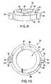
- FIG. 9shows a perspective view of a washer according to one embodiment of the present invention.
- FIG. 10shows a top view of the washer of FIG. 10 .
- FIG. 11shows a cross-sectional view of the washer of FIG. 9
- FIG. 12shows a top view of another embodiment of a washer according to the present invention.
- FIG. 13shows a side view of a set screw according to one embodiment of the present invention.
- FIG. 14shows a top view of the set screw of FIG. 13 .
- FIG. 15shows a cross-sectional view of an external set screw according to another embodiment of the present invention.
- FIG. 16shows a top view of the external set screw of FIG. 15 .
- FIG. 17shows a perspective view of a snap ring for use in the present invention.
- FIG. 17 ashows a side view of an alternative embodiment of a snap ring for use in the present invention.
- FIG. 18shows a top view of the snap ring of FIG. 17 .
- FIG. 19shows a partial cross-sectional view of a bone anchor assembly according to another embodiment of the present invention.
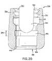
- FIG. 20shows a cross-sectional view of an embodiment of a saddle member shown in FIG. 19 .
- FIG. 21shows a top view of the saddle member of FIG. 20 .
- FIG. 22shows a cross-sectional view of a washer shown in FIG. 19 .
- FIG. 23shows a bottom view of the saddle member according to one embodiment of the present invention.
- FIG. 24shows an isometric view of a saddle member of FIG. 23 .
- FIG. 25shows a bottom view of the saddle member according to one embodiment of the present invention.
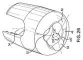
- FIG. 26shows an isometric view of a saddle member of FIG. 25 .
- FIG. 27shows a cross-sectional view of the saddle member according to one embodiment of the present invention.
- Bone anchor assembly 20includes a saddle member 22 , a bone anchoring member 24 , and set screw member 30 .
- Saddle member 22generally has a U-shape, with two upright portions 32 defining a channel 34 extending through saddle member 22 .
- Channel 34is then configured to accommodate an elongated member 36 , such as a spinal rod.
- rod 36may have one of a number of desired lengths and diameters. As seen in FIG.
- the width of channel 34is slightly larger than the diameter of rod 36 , which allows easier insertion of rod 36 into channel 34 , also allows for compensation for contouring of the rod, and allows use of a range of rod sizes with the same saddle member 22 .
- the curved bottoms 255shown in FIG. 3 , of channel 34 are arranged such that the top of the head portion 58 of the of bone anchor member 24 , when fully nested into the lower portion of hole 38 , extends above the edge of the curved bottoms 255 of channel 34 such that rod 36 positioned in channel 34 will pressingly engage the head portion 58 of bone anchor member 24 .
- Saddle member 22further includes a hole 38 therethrough, the axis of hole 38 being substantially perpendicular to the axis of channel 34 .
- upright portions 32each have an outer surface 40 and an inner surface 42 .
- Inner surfaces 42are substantially parallel to the axis of hole 38 , along a longitudinal axis of saddle member 22 .
- outer surfaces 40are angled with respect to inner surfaces 42 and the longitudinal axis of saddle member 22 with an inward taper, which taper allows for easier handling of the saddle member 22 and reduced bulk of saddle member 22 .
- hole 38is narrowed by a wall portion 44 .
- the wall portion 44contains a section 59 that is circular and the plane of which is substantially perpendicular to the longitudinal axis of hole 38 .
- wall portion 44 and section 59may be of any shape as long as the diameter of hole 38 at section 59 of wall portion 44 is greater than that of shank 72 and less than that of head portion 58 of the of bone anchor member 24 .
- Upright portions 32further include an internally threaded portion 52 , as shown in FIG. 1 .
- Internally threaded portion 52is configured to be threadedly coupled with set screw 30 , as described below.
- the internally threaded portions 52 a and 52 drespectively are configured so that they end above rod 36 when set screw 30 is secured in saddle member 22 .
- saddle member 22includes a relief groove 16 that extends around hole 38 . Relief groove 16 eliminates the helical thread run out typically found on internal threads. In other embodiments, saddle member 22 does not contain a relief groove.
- upright portions 32may include an externally threaded portions 164 , as shown in FIG. 4 instead of an internally threaded portions.
- Externally threaded portions 164are configured to be threadedly coupled with external set screw 30 a , as described hereafter.
- outer surfaces 40are parallel to one another.
- hole 38opens outward by virtue of a conical wall portion 46 .
- Conical wall portion 46allows bone anchor member 24 to be positioned in any of an infinite number of limited angular positions relative to the longitudinal axis of the saddle member 22 by reducing interference of the lower portion of saddle member 22 with a shank portion 72 of bone anchor member 24 .
- wall portion 44 conical wall portion 46contain angular cutouts 62 placed symmetrically about the longitudinal axis of hole 38 to increase the allowable angulation of the bone screw in relation to the longitudinal axis of hole 38 .
- Any number of cutouts, the shape of the cutouts, the position of the cutouts in relation to the axis of channel 34 , the angle of the cutouts in relation to a plane that is perpendicular to the axis of hole 38 , the size of the cutouts and the angular spacing between each cutoutmay vary for specific applications.
- Two of angular cutouts 62being offset 30 degrees from the axis of channel 34 and all three angular cutouts 62 are spaced 120 degrees apart from one another. As shown in the embodiment in FIGS. 25 and 26 , there are three angular cutouts that are generally cylindrical in shape. One of angular cutouts 62 being on the axis of channel 34 and all three angular cutouts 62 are spaced 120 degrees apart from one another.
- one embodiment of the bone anchor member 24 of the present inventionhas a threaded portion 56 containing threads 60 , a shank 72 and a head portion 58 .
- Head portion 58 of bone anchor member 24 in one embodimentis substantially spherical. However it should be understood that any external contour which is equidistant from the center point of the head portion 58 could be utilized.
- a tool-engaging recess 76is formed in the upper portion of head portion 58 . The specific shape of tool-engaging recess 76 may be chosen to cooperate with any suitable screw-driving tool.
- the diameter of the threaded portion 56should be less than the diameter of the head portion 58 , and the shank 72 should be narrower than the widest portion of threaded portion 56 .
- any head design, shaft design, thread pitch or tip taper suitable for insertion into a vertebral bodycan be utilized. Threaded portion 56 can even be larger than head portion 58 if the thread pitch allows threading through wall portion 44 .
- Multi-axial bone anchor assembly 20may further include a set screw 30 .
- set screw 30is generally cylindrical and has external threads 102 .
- External threads 102are buttress threads.
- threads 102could be reverse angle threads so as to minimize splaying between the two upright members 32 .
- An example of such reverse angle threadingis disclosed in U.S. Pat. No. 6,296,642, which is hereby incorporated by reference.
- this embodiment of set screw 30includes a substantially flat end surface 110 in order to minimize the profile of assembly 20 .
- Set screw 30further includes a tool-engaging bore 112 .
- Tool-engaging bore 112is used in conjunction with a tool for introducing set screw 30 into saddle member 22 .
- set screw 30 acomprises internal threading 202 which is intended to mate with external threading 164 on the upwardly extending members 32 of saddle member 22 .
- the set screwalso comprises an inner plug portion 300 having a bottom surface which is intended to seat against the top surface of rod 36 seated in saddle 22 , providing a means for driving the rod 36 downward against the head portion of bone anchor member 24 in one embodiment and against the washer 26 in another embodiment.
- the bottom surface 301 of inner plug 300comprises a plurality of raised metal projections to engage and press into rod 36 .
- Set screw 30 ahas at one end a tool-engaging bore 112 . As illustrated in FIG.
- set screw 30 amay also include a rounded end surface 206 to reduce internal trauma to a patient or a substantially flat end surface in order to minimize the profile of assembly 20 .
- Tool-engaging bore 112is used in conjunction with a tool for introducing set screw 30 a onto saddle member 22 .
- bone anchor assembly 20 aincludes a bone anchoring member 24 and a set screw member 30 .
- this embodimentalso comprises a washer (crown member) 26 .
- the internally threaded portions 52 aare configured so that they end above rod 36 when set screw 30 is secured in saddle member 22 .
- Saddle member 22further includes a relief groove 16 that extends around hole 38 .
- assembly 20 awill further include a C-shaped snap ring 28 , which are fitted with saddle member 22 as will be described hereafter.
- the illustrated embodiment of FIGS. 2 , 5 and 7also comprises a saddle member 22 that further includes an inner groove 48 that extends around hole 38 .
- Groove 48is configured to accommodate snap ring 28 in a compressed condition, i.e., the outer diameter of groove 48 is at least slightly smaller than the normal uncompressed outer diameter of snap ring 28 .
- the illustrated embodiment of saddle assembly 22further includes one or more troughs 50 extending longitudinally within each of upright portions 32 .
- the one or more troughs 50accommodates placement of washer 26 , as further described below, and may have a rounded (e.g. cylindrical), squared, or other appropriate shape to accommodate washer 26 .
- the curved bottoms 255 of channel 34are arranged such that when rod 36 is inserted therein, rod 36 will pressingly engage the washer 26 which will itself pressingly engage the head portion 58 of bone anchor member 24 .
- Washer 26includes an upper portion 80 , a lower portion 82 , and a hole 84 therethrough.
- Upper portion 80 and lower portion 82may be constructed integrally or may be separately constructed and attached together in any known manner.
- An upper surface 86 of upper portion 80may include recessed portions 88 in the illustrated embodiment, which recessed portions 88 form a part of a cylinder sized and configured to accommodate placement of an elongated member (such as rod 36 of FIG. 1 ) therein.
- Lower portion 82further includes an upper surface 83 that faces snap ring 28 .
- washer 26has a hole 84 provided through both upper portion 80 and lower portion 82 .
- Hole 84includes a lower concave surface 96 and a cylindrical surface 98 .
- Concave surface 96in one specific embodiment has a spherical shape so as to substantially coincide with a portion of head portion 58 of anchoring member 24 .
- Lower portion 82is generally in the shape of a circular disc, and may include one or more projections 90 extending radially therefrom. Projections 90 in conjunction with troughs 50 align recessed portions 88 of washer 26 with channel 34 a and prevent rotation of washer 26 so as to minimize misalignment between rod 36 and recessed portions 88 .
- projections 90each include two substantially planar side surfaces 92 , and an end surface 94 that is rounded and may form a portion of a cylinder. Projections 90 are sized and shaped so as to fit and slide easily within the troughs 50 upright portions 32 a of saddle member 22 . In another embodiment illustrated in FIG. 12 , projections 90 a each include a rounded end surface 100 .
- multi-axial bone anchor assembly 20 aincludes snap ring 28 in order to secure washer 26 against anchoring member 24 .
- Snap ring 28has a central opening 114 and a compression slot 116 defined therein. Snap ring 28 further has a first surface 118 , an opposite second surface 120 , an inner lateral surface 122 defining opening 114 , and an outer lateral surface 124 . Compression slot 116 allows snap ring 28 to compress and fit into inner groove 48 of saddle member 22 . The diameter of the entrance of groove 48 is at least slightly smaller than the outer diameter 126 of an uncompressed snap ring 28 .
- Opening 114 of snap ring 28has an inner diameter 128 , which allows snap ring 28 to fit around upper portion 80 of washer 26 .
- One of the surfaces 118 and 120engage the upper surface 83 of lower portion 82 in order to secure washer 26 .
- Snap ring 28can have a square cross-section, as shown in FIG. 2 , or a circular or other appropriate shape cross-section, and in one particular embodiment is made of a shape memory alloy such as nitinol.
- FIG. 17 aAnother embodiment of snap ring 28 ′ is illustrated in FIG. 17 a .
- Snap ring 28 ′is non-planar, and in one embodiment has a series of undulations forming relative crests 129 a and relative troughs 129 b therein.
- non-planar snap ring 28 ′could have other curved configurations, or could have extending finger-spring elements along it.
- non-planar snap ring 28 ′allows less play between saddle member 22 , anchoring member 24 and washer 26 because non-planar snap-ring 28 ′ fills a greater portion of groove 48 of saddle member 22 .
- bone anchor assembly 20 dincludes a bone anchoring member 24 and a set screw member 30 .
- this embodimentalso comprises a washer (crown member) 26 d .
- assembly 20 dwill further include a C-shaped snap ring 28 , which are fitted with saddle member 22 d as will be described hereafter.
- the particular illustrated embodiment of saddle member 22 dmay include an inner groove 48 d .
- groove 48 dextends around hole 38 d , and in this particular embodiment, groove 48 d is uniform between a top portion of groove 48 d and the bottom portion thereof.
- Groove 48 dis configured to accommodate snap ring 28 in a compressed condition.
- Groove 48 dhas a thickness 264 that is, in one form, larger than snap ring 28 .
- the illustrated embodiment of saddle assembly 22 d in FIGS. 20-21does not include a trough 50 that extends longitudinally within each of upright portions 32 d .
- Upright portions 32 dfurther include internally threaded portions 52 d , which are configured to be threadedly coupled with set screw 30 .
- Washer 26 dincludes an upper portion 80 d , a lower portion 82 d , a snap ring recess 266 , and a hole 84 d therethrough.
- Upper portion 80 d , lower portion 82 d , and snap ring recess 266may be constructed integrally or may be separately constructed and attached together in any known manner.
- Snap ring 28fits within recess 266 in order to secure washer 26 d within saddle member 22 d .
- assembly 20 dis assembled by inserting anchoring member 24 a through hole 38 d in saddle member 22 d .
- Washer 26 dwith snap ring 28 in at least a portion of recess 266 , is then inserted into hole 38 d .
- Snap ring 28contracts into recess 266 as washer 26 d goes through saddle member 22 d , and expands into groove 48 d to hold washer 26 d within saddle member 22 d .
- An elongated memberis then inserted in channel 34 d , and a set screw (such as those described above) is threaded into internally threaded portions 52 d , saddle member 22 d to lock the elongated member, washer 26 d and anchoring member 24 a together.
- Washer 26 dhas a hole 84 d provided through both upper portion 80 d and lower portion 82 d .
- Hole 84 dincludes a lower concave surface 96 d and a cylindrical surface 98 d .
- Lower concave surface 96 d opposite from upper surface 86 dis adapted to accommodate head portion 58 a of anchor member 24 a .
- lower portion 82 dis generally in the shape of a circular disc. In this particular embodiment, lower portion 82 d does not have projections 90 .
Landscapes
- Health & Medical Sciences (AREA)
- Orthopedic Medicine & Surgery (AREA)
- Life Sciences & Earth Sciences (AREA)
- Neurology (AREA)
- Surgery (AREA)
- Heart & Thoracic Surgery (AREA)
- Engineering & Computer Science (AREA)
- Biomedical Technology (AREA)
- Nuclear Medicine, Radiotherapy & Molecular Imaging (AREA)
- Medical Informatics (AREA)
- Molecular Biology (AREA)
- Animal Behavior & Ethology (AREA)
- General Health & Medical Sciences (AREA)
- Public Health (AREA)
- Veterinary Medicine (AREA)
- Surgical Instruments (AREA)
- Prostheses (AREA)
Abstract
Description
The present invention generally relates to orthopedic implants used for correction of spinal injuries or deformities, and more specifically, but not exclusively, concerns apparatuses for fixing a portion of the spine, such as the cervical spine, to allow correction or healing thereof.
In the field of spinal surgery, it is known to place implants into vertebrae for a number of reasons, including (a) correcting an abnormal curvature of the spine, including a scoliotic curvature, (b) to maintain appropriate spacing and provide support to broken or otherwise injured vertebrae, and (c) perform other therapies on the spinal column.
Typical implant systems utilize a rod as the support and stabilizing member. In such an implant, a series of two or more screws are inserted into two or more vertebrae to be instrumented. A rod is then placed within or coupled to the heads of the screws, or is placed within a connecting device that links the rod and a screw head, and the connections are secured. In this way, a supporting structure is fixed to the vertebrae.
Many varieties of bone fixation screws are mono-axial in construction. That is, such devices are connected to the rod or plate such that a longitudinal axis through the rod or plate and a longitudinal axis through the fixation device are capable of only a single position with respect to each other. While useful in certain circumstances, in many therapeutic situations the degree of precision required to use such an inflexible device is impractical.
More recently, bone fixation devices having multi-axial capability have been introduced. Examples of such constructs are shown in U.S. Pat. Nos. 5,797,911, 5,954,725, 5,810,818 and 6,485,491 which is hereby incorporated by reference. These devices help to reduce the required precision of placement of the fixation device, since the saddle portion of the fixation device is multi-axially positionable on the anchor member portion. The saddle portion can thus be positioned so as to easily receive the rod, limiting or removing much of the positioning difficulty inherent in prior devices.
Most such devices are designed for spinal fixation at the thoracic and lumbar levels and allow only a limited angulation of the anchor member in relation to the saddle member. There is a need in the art for a multi-axial bone attachment assembly, and particularly one that is useful in the cervical region of the spine with a greater degree of such angulation.
One embodiment of the present invention is a unique multi-axial bone attachment assembly that includes a saddle member and a bone anchoring member. The saddle member has a plurality of upright portions that define a channel through the saddle member. The saddle member further has a hole therethrough bounded by an inner wall, and the hole forms a lower opening in the saddle member. The lower opening in the saddle member may contain angular cutouts placed symmetrically about the axis of the saddle to increase the allowable angulation of the bone screw in relationship to the axis of the saddle. The position, angle and number of cutouts may vary as required by the application of the multi-axial bone attachment assembly. The bone-anchoring member extends through the opening. The bone-anchoring member includes a head portion and an anchoring portion. A further embodiment of the present invention includes a washer (crown member). The washer may have a recessed portion for accommodating an orthopedic rod and may include a radially extending projection. The washer is fitted within the hole of the saddle member and atop the bone-anchoring member.
Further features and practical advantages of different embodiments of the invention will emerge from the description of the exemplified embodiments with reference to the figures.
Reference will now be made to the embodiments illustrated in the drawings and specific language will be used to describe the same. It will nevertheless be understood that no limitation of the scope of the invention is thereby intended, such alterations and further modifications in the illustrated device, and such further applications of the principles of embodiments of the invention as illustrated therein, being contemplated as would normally occur to one skilled in the art to which the invention relates.
InFIG. 1 , there is shown an embodiment of a multi-axialbone anchor assembly 20.Bone anchor assembly 20 includes asaddle member 22, abone anchoring member 24, and setscrew member 30.Saddle member 22 generally has a U-shape, with twoupright portions 32 defining achannel 34 extending throughsaddle member 22. Channel34 is then configured to accommodate anelongated member 36, such as a spinal rod. For posterior cervical fixation,rod 36 may have one of a number of desired lengths and diameters. As seen inFIG. 1 , the width ofchannel 34 is slightly larger than the diameter ofrod 36, which allows easier insertion ofrod 36 intochannel 34, also allows for compensation for contouring of the rod, and allows use of a range of rod sizes with thesame saddle member 22. Thecurved bottoms 255, shown inFIG. 3 , ofchannel 34 are arranged such that the top of thehead portion 58 of the ofbone anchor member 24, when fully nested into the lower portion ofhole 38, extends above the edge of thecurved bottoms 255 ofchannel 34 such thatrod 36 positioned inchannel 34 will pressingly engage thehead portion 58 ofbone anchor member 24.Saddle member 22 further includes ahole 38 therethrough, the axis ofhole 38 being substantially perpendicular to the axis ofchannel 34.
In the particular embodiments ofsaddle member 22, illustrated inFIGS. 1 ,2 and19,upright portions 32 each have anouter surface 40 and aninner surface 42.Inner surfaces 42 are substantially parallel to the axis ofhole 38, along a longitudinal axis ofsaddle member 22. In the embodiment shown inFIG. 3 ,outer surfaces 40 are angled with respect toinner surfaces 42 and the longitudinal axis ofsaddle member 22 with an inward taper, which taper allows for easier handling of thesaddle member 22 and reduced bulk ofsaddle member 22. Near the bottom ofsaddle member 22,hole 38 is narrowed by awall portion 44. In one embodiment thewall portion 44 contains asection 59 that is circular and the plane of which is substantially perpendicular to the longitudinal axis ofhole 38. Howeverwall portion 44 andsection 59 may be of any shape as long as the diameter ofhole 38 atsection 59 ofwall portion 44 is greater than that ofshank 72 and less than that ofhead portion 58 of the ofbone anchor member 24.
Belowwall portion 44,hole 38 opens outward by virtue of aconical wall portion 46.Conical wall portion 46 allowsbone anchor member 24 to be positioned in any of an infinite number of limited angular positions relative to the longitudinal axis of thesaddle member 22 by reducing interference of the lower portion ofsaddle member 22 with ashank portion 72 ofbone anchor member 24.
As shown inFIGS. 23-27 ,wall portion 44conical wall portion 46 containangular cutouts 62 placed symmetrically about the longitudinal axis ofhole 38 to increase the allowable angulation of the bone screw in relation to the longitudinal axis ofhole 38. Any number of cutouts, the shape of the cutouts, the position of the cutouts in relation to the axis ofchannel 34, the angle of the cutouts in relation to a plane that is perpendicular to the axis ofhole 38, the size of the cutouts and the angular spacing between each cutout may vary for specific applications. As shown in the embodiment inFIGS. 23 and 24 , there are three angular cutouts that are generally cylindrical in shape. Two ofangular cutouts 62 being offset 30 degrees from the axis ofchannel 34 and all threeangular cutouts 62 are spaced 120 degrees apart from one another. As shown in the embodiment inFIGS. 25 and 26 , there are three angular cutouts that are generally cylindrical in shape. One ofangular cutouts 62 being on the axis ofchannel 34 and all threeangular cutouts 62 are spaced 120 degrees apart from one another.
As shown inFIG. 8 , one embodiment of thebone anchor member 24 of the present invention has a threadedportion 56 containingthreads 60, ashank 72 and ahead portion 58.Head portion 58 ofbone anchor member 24 in one embodiment is substantially spherical. However it should be understood that any external contour which is equidistant from the center point of thehead portion 58 could be utilized. In the illustrated embodiment, a tool-engagingrecess 76 is formed in the upper portion ofhead portion 58. The specific shape of tool-engagingrecess 76 may be chosen to cooperate with any suitable screw-driving tool. In relation to each other, the diameter of the threadedportion 56 should be less than the diameter of thehead portion 58, and theshank 72 should be narrower than the widest portion of threadedportion 56. As is apparent, any head design, shaft design, thread pitch or tip taper suitable for insertion into a vertebral body can be utilized. Threadedportion 56 can even be larger thanhead portion 58 if the thread pitch allows threading throughwall portion 44.
Multi-axialbone anchor assembly 20 may further include aset screw 30. In the embodiments, illustrated inFIGS. 13-14 , setscrew 30 is generally cylindrical and hasexternal threads 102.External threads 102, in one embodiment, are buttress threads. In another embodiment,threads 102 could be reverse angle threads so as to minimize splaying between the twoupright members 32. An example of such reverse angle threading is disclosed in U.S. Pat. No. 6,296,642, which is hereby incorporated by reference.
As illustrated inFIGS. 13-14 , this embodiment ofset screw 30 includes a substantiallyflat end surface 110 in order to minimize the profile ofassembly 20. Setscrew 30 further includes a tool-engagingbore 112. Tool-engagingbore 112 is used in conjunction with a tool for introducing setscrew 30 intosaddle member 22.
In another embodiment, as illustrated inFIGS. 15-16 , setscrew 30acomprisesinternal threading 202 which is intended to mate withexternal threading 164 on the upwardly extendingmembers 32 ofsaddle member 22. The set screw also comprises aninner plug portion 300 having a bottom surface which is intended to seat against the top surface ofrod 36 seated insaddle 22, providing a means for driving therod 36 downward against the head portion ofbone anchor member 24 in one embodiment and against thewasher 26 in another embodiment. In another embodiment, thebottom surface 301 ofinner plug 300 comprises a plurality of raised metal projections to engage and press intorod 36. Setscrew 30ahas at one end a tool-engagingbore 112. As illustrated inFIG. 15 , setscrew 30amay also include arounded end surface 206 to reduce internal trauma to a patient or a substantially flat end surface in order to minimize the profile ofassembly 20. Tool-engagingbore 112 is used in conjunction with a tool for introducing setscrew 30aontosaddle member 22.
InFIG. 2 , there is shown a multi-axialbone anchor assembly 20aaccording to another embodiment of the present invention. Similar to the embodiment inFIG. 1 and described above,bone anchor assembly 20aincludes abone anchoring member 24 and aset screw member 30. However, this embodiment also comprises a washer (crown member)26. Also in this embodiment, the internally threaded portions52aare configured so that they end aboverod 36 when setscrew 30 is secured insaddle member 22.Saddle member 22 further includes arelief groove 16 that extends aroundhole 38. In some embodiments,assembly 20awill further include a C-shapedsnap ring 28, which are fitted withsaddle member 22 as will be described hereafter.
The illustrated embodiment ofFIGS. 2 ,5 and7 also comprises asaddle member 22 that further includes aninner groove 48 that extends aroundhole 38.Groove 48 is configured to accommodatesnap ring 28 in a compressed condition, i.e., the outer diameter ofgroove 48 is at least slightly smaller than the normal uncompressed outer diameter ofsnap ring 28. The illustrated embodiment ofsaddle assembly 22 further includes one ormore troughs 50 extending longitudinally within each ofupright portions 32. The one ormore troughs 50 accommodates placement ofwasher 26, as further described below, and may have a rounded (e.g. cylindrical), squared, or other appropriate shape to accommodatewasher 26. In this embodiment, thecurved bottoms 255 ofchannel 34 are arranged such that whenrod 36 is inserted therein,rod 36 will pressingly engage thewasher 26 which will itself pressingly engage thehead portion 58 ofbone anchor member 24.
Referring now toFIGS. 9-12 , there is shown an embodiment ofwasher 26 of the present invention.Washer 26 includes anupper portion 80, alower portion 82, and ahole 84 therethrough.Upper portion 80 andlower portion 82 may be constructed integrally or may be separately constructed and attached together in any known manner. Anupper surface 86 ofupper portion 80 may include recessedportions 88 in the illustrated embodiment, which recessedportions 88 form a part of a cylinder sized and configured to accommodate placement of an elongated member (such asrod 36 ofFIG. 1 ) therein.Lower portion 82 further includes anupper surface 83 that facessnap ring 28.
Referring now toFIG. 11 ,washer 26 has ahole 84 provided through bothupper portion 80 andlower portion 82.Hole 84 includes a lowerconcave surface 96 and acylindrical surface 98.Concave surface 96 in one specific embodiment has a spherical shape so as to substantially coincide with a portion ofhead portion 58 of anchoringmember 24.Lower portion 82 is generally in the shape of a circular disc, and may include one ormore projections 90 extending radially therefrom.Projections 90 in conjunction withtroughs 50 align recessedportions 88 ofwasher 26 withchannel 34aand prevent rotation ofwasher 26 so as to minimize misalignment betweenrod 36 and recessedportions 88.
In one embodiment, shown inFIGS. 9-10 ,projections 90 each include two substantially planar side surfaces92, and anend surface 94 that is rounded and may form a portion of a cylinder.Projections 90 are sized and shaped so as to fit and slide easily within thetroughs 50upright portions 32aofsaddle member 22. In another embodiment illustrated inFIG. 12 ,projections 90aeach include arounded end surface 100.
In certain embodiments, multi-axialbone anchor assembly 20aincludessnap ring 28 in order to securewasher 26 against anchoringmember 24. One embodiment of such asnap ring 28 is shown inFIGS. 17-18 .Snap ring 28 has acentral opening 114 and acompression slot 116 defined therein.Snap ring 28 further has afirst surface 118, an oppositesecond surface 120, an innerlateral surface 122 definingopening 114, and an outerlateral surface 124.Compression slot 116 allowssnap ring 28 to compress and fit intoinner groove 48 ofsaddle member 22. The diameter of the entrance ofgroove 48 is at least slightly smaller than theouter diameter 126 of anuncompressed snap ring 28. Opening114 ofsnap ring 28 has aninner diameter 128, which allowssnap ring 28 to fit aroundupper portion 80 ofwasher 26. One of thesurfaces upper surface 83 oflower portion 82 in order to securewasher 26.Snap ring 28 can have a square cross-section, as shown inFIG. 2 , or a circular or other appropriate shape cross-section, and in one particular embodiment is made of a shape memory alloy such as nitinol.
Another embodiment ofsnap ring 28′ is illustrated inFIG. 17 a.Snap ring 28′ is non-planar, and in one embodiment has a series of undulations formingrelative crests 129aandrelative troughs 129btherein. Alternatively,non-planar snap ring 28′ could have other curved configurations, or could have extending finger-spring elements along it. Whenassembly 20ais assembled,non-planar snap ring 28′ allows less play betweensaddle member 22, anchoringmember 24 andwasher 26 because non-planar snap-ring 28′ fills a greater portion ofgroove 48 ofsaddle member 22.
InFIG. 19 , there is shown another embodiment of a multi-axialbone anchor assembly 20daccording to another embodiment of the present invention. Similar to the embodiment inFIG. 1 and described above,bone anchor assembly 20dincludes abone anchoring member 24 and aset screw member 30. However, this embodiment also comprises a washer (crown member)26d. In some embodiments,assembly 20dwill further include a C-shapedsnap ring 28, which are fitted withsaddle member 22das will be described hereafter.
The particular illustrated embodiment ofsaddle member 22dmay include aninner groove 48d. As illustrated, groove48dextends aroundhole 38d, and in this particular embodiment, groove48dis uniform between a top portion ofgroove 48dand the bottom portion thereof.Groove 48dis configured to accommodatesnap ring 28 in a compressed condition.Groove 48dhas athickness 264 that is, in one form, larger thansnap ring 28. Further, the illustrated embodiment ofsaddle assembly 22dinFIGS. 20-21 does not include atrough 50 that extends longitudinally within each ofupright portions 32d.Upright portions 32dfurther include internally threadedportions 52d, which are configured to be threadedly coupled withset screw 30.
Referring now toFIG. 22 , there is shown another embodiment ofwasher 26daccording to the present invention.Washer 26dincludes anupper portion 80d, alower portion 82d, asnap ring recess 266, and ahole 84dtherethrough.Upper portion 80d,lower portion 82d, andsnap ring recess 266 may be constructed integrally or may be separately constructed and attached together in any known manner.Snap ring 28 fits withinrecess 266 in order to securewasher 26dwithinsaddle member 22d. In one embodiment,assembly 20dis assembled by inserting anchoringmember 24athroughhole 38dinsaddle member 22d.Washer 26d, withsnap ring 28 in at least a portion ofrecess 266, is then inserted intohole 38d.Snap ring 28 contracts intorecess 266 aswasher 26dgoes throughsaddle member 22d, and expands intogroove 48dto holdwasher 26dwithinsaddle member 22d. An elongated member is then inserted inchannel 34d, and a set screw (such as those described above) is threaded into internally threadedportions 52d,saddle member 22dto lock the elongated member,washer 26dand anchoringmember 24atogether.
While embodiments of the invention have been illustrated and described in detail in the drawings and foregoing description, the same is to be considered as illustrative and not restrictive in character. It should be understood that only the preferred embodiments have been shown and described.
Claims (39)
1. A multi-axial bone attachment assembly, comprising:
a bone anchoring member comprising a head portion and an anchoring portion;
a saddle member having a plurality of upright portions that define a channel through said saddle member such that an elongated rod may be received therein, wherein said upright portions include threaded portions, said saddle member further having a hole therethrough bounded by an inner wall through which said bone anchoring member may be inserted, said hole forming a lower opening in said saddle member that engages the head of the bone anchoring member such that the head of the bone anchoring member is prevented from passing therethrough, wherein said lower opening contains a plurality of angular cutouts placed symmetrically about the longitudinal axis the saddle member, the plurality of angular cutouts sized to receive a portion of the bone anchoring member to increase an allowable angulation of the bone anchoring member in relation to a longitudinal axis of the hole; and
a set screw for threadedly engaging the threaded portions of the plurality of upright portions, said set screw further comprising an engaging portion for engaging the elongated rod.
2. The assembly ofclaim 1 , wherein said upright portions are internally threaded, and said set screw is externally threaded.
3. The assembly ofclaim 2 , wherein said threaded portions have reverse angle threads.
4. The assembly ofclaim 1 , wherein said upright portions are externally threaded, and said set screw is internally threaded.
5. The assembly ofclaim 4 , wherein said set screw includes an upper surface that is convexly rounded.
6. The assembly ofclaim 4 , wherein said threaded portions have reverse angle threads.
7. The assembly ofclaim 1 , wherein said anchoring member is a bone screw.
8. The assembly ofclaim 7 , wherein said bone screw includes a head portion having a convex underside.
9. The assembly ofclaim 8 , wherein said convex underside is spherical.
10. The assembly ofclaim 1 , wherein the threaded portions are located above the elongated rod when the set screw is fully threadedly engaged within the plurality of upright portions.
11. The assembly ofclaim 10 , wherein the inner wall includes a relief groove adjacent to the threaded portions.
12. The assembly ofclaim 1 , further comprising a washer for accommodating the elongated rod, said washer being fitted within said hole of said saddle member and atop said bone anchoring member.
13. The assembly ofclaim 12 , wherein the washer comprises a recessed portion for accommodating the elongated rod.
14. The assembly ofclaim 13 , wherein said inner wail includes a groove, said assembly further comprises a snap-ring fitted into said groove to hold said washer in said hole of said saddle member.
15. The assembly ofclaim 13 , wherein said upright portions each have one or more troughs defined therein, said washer includes one or more alignment members to mate therewith to minimize misalignment between the rod and said recessed portion.
16. The assembly ofclaim 15 , wherein said upright portions are internally threaded, and said set screw is externally threaded.
17. The assembly ofclaim 15 , wherein said upright portions are externally threaded, and said set screw is internally threaded.
18. The assembly ofclaim 12 , wherein the threaded portions are located above the elongated rod when the set screw is fully threadedly engaged within the plurality of upright portions.
19. The assembly ofclaim 18 , wherein the inner wall includes a relief groove adjacent to the threaded portions.
20. A multi-axial bone attachment assembly, comprising:
a bone anchoring member comprising a head portion and an anchoring portion;
a saddle member having a plurality of upright portions that define a channel through said saddle member such that an elongated rod may be received therein, wherein said upright portions include threaded portions, said saddle member further having a hole therethrough bounded by an inner wall through which said bone anchoring member may be inserted, said hole forming a lower circular opening in said saddle member that engages the head of the bone anchoring member such that the head of the bone anchoring member is prevented from passing therethrough, wherein said lower opening contains a plurality of angular cutouts placed symmetrically about the longitudinal axis the saddle member, the plurality of angular cutouts sized to receive a portion of the bone anchoring member to increase an allowable angulation of the bone anchoring member in relation to the longitudinal axis of the saddle member; and
a set screw for threadedly engaging the threaded portions of the plurality of upright portions, said set screw further comprising an engaging portion for engaging the elongated rod.
21. The assembly ofclaim 20 , wherein the circular opening is planar and substantially perpendicular to the longitudinal axis the saddle member.
22. The assembly ofclaim 20 , wherein said upright portions are internally threaded, and said set screw is externally threaded.
23. The assembly ofclaim 22 , wherein said threaded portions have reverse angle threads.
24. The assembly ofclaim 20 , wherein said upright portions are externally threaded, and said set screw is internally threaded.
25. The assembly ofclaim 24 , wherein said set screw includes an upper surface that is convexly rounded.
26. The assembly ofclaim 24 , wherein said threaded portions have reverse angle threads.
27. The assembly ofclaim 20 , wherein said anchoring member is a bone screw.
28. The assembly ofclaim 27 , wherein said bone screw includes a head portion having a convex underside.
29. The assembly ofclaim 28 , wherein said convex underside is spherical.
30. The assembly ofclaim 20 , wherein the threaded portions are located above the elongated rod when the set screw is fully threadedly engaged within the plurality of upright portions.
31. The assembly ofclaim 30 , wherein the inner wall includes a relief groove adjacent to the threaded portions.
32. The assembly ofclaim 20 , further comprising a washer for accommodating the elongated rod, said washer being fitted within said hole of said saddle member and atop said bone anchoring member.
33. The assembly ofclaim 32 , wherein the washer comprises a recessed portion for accommodating the elongated rod.
34. The assembly ofclaim 33 , wherein said inner wall includes a groove, said assembly further comprises a snap-ring fitted into said groove to hold said washer in said hole of said saddle member.
35. The assembly ofclaim 34 , wherein said upright portions each have one or more troughs defined therein, said washer includes one or more alignment members to mate therewith to minimize misalignment between the rod and said recessed portion.
36. The assembly ofclaim 35 , wherein said upright portions are internally threaded, and said set screw is externally threaded.
37. The assembly ofclaim 35 , wherein said upright portions are externally threaded, and said set screw is internally threaded.
38. The assembly ofclaim 32 , wherein the threaded portions are located above the elongated rod when the set screw is fully threadedly engaged within the plurality of upright portions.
39. The assembly ofclaim 38 , wherein the inner wall includes a relief groove adjacent to the threaded portions.
Priority Applications (8)
| Application Number | Priority Date | Filing Date | Title |
|---|---|---|---|
| US10/870,011US7264621B2 (en) | 2004-06-17 | 2004-06-17 | Multi-axial bone attachment assembly |
| JP2007516715AJP4814227B2 (en) | 2004-06-17 | 2005-06-16 | Multiaxial bone mounting assembly |
| AU2005265015AAU2005265015B2 (en) | 2004-06-17 | 2005-06-16 | Multi-axial bone attachment assembly |
| PCT/US2005/021227WO2006009753A1 (en) | 2004-06-17 | 2005-06-16 | Multi-axial bone attachment assembly |
| KR1020077001199AKR100816975B1 (en) | 2004-06-17 | 2005-06-16 | Multi-Axial Bone Attachment Assembly |
| EP05760664.2AEP1768587B1 (en) | 2004-06-17 | 2005-06-16 | Multi-axial bone attachment assembly |
| CA002572794ACA2572794A1 (en) | 2004-06-17 | 2005-06-16 | Multi-axial bone attachment assembly |
| CN200580024659XACN101389279B (en) | 2004-06-17 | 2005-06-16 | polyaxial bone attachment assembly |
Applications Claiming Priority (1)
| Application Number | Priority Date | Filing Date | Title |
|---|---|---|---|
| US10/870,011US7264621B2 (en) | 2004-06-17 | 2004-06-17 | Multi-axial bone attachment assembly |
Publications (2)
| Publication Number | Publication Date |
|---|---|
| US20050283157A1 US20050283157A1 (en) | 2005-12-22 |
| US7264621B2true US7264621B2 (en) | 2007-09-04 |
Family
ID=35106641
Family Applications (1)
| Application Number | Title | Priority Date | Filing Date |
|---|---|---|---|
| US10/870,011Expired - LifetimeUS7264621B2 (en) | 2004-06-17 | 2004-06-17 | Multi-axial bone attachment assembly |
Country Status (8)
| Country | Link |
|---|---|
| US (1) | US7264621B2 (en) |
| EP (1) | EP1768587B1 (en) |
| JP (1) | JP4814227B2 (en) |
| KR (1) | KR100816975B1 (en) |
| CN (1) | CN101389279B (en) |
| AU (1) | AU2005265015B2 (en) |
| CA (1) | CA2572794A1 (en) |
| WO (1) | WO2006009753A1 (en) |
Cited By (101)
| Publication number | Priority date | Publication date | Assignee | Title |
|---|---|---|---|---|
| US20050277919A1 (en)* | 2004-05-28 | 2005-12-15 | Depuy Spine, Inc. | Anchoring systems and methods for correcting spinal deformities |
| US20080015586A1 (en)* | 2006-06-07 | 2008-01-17 | Disc Motion Technologies, Inc. | Pedicle screw system |
| US20080269742A1 (en)* | 2007-04-25 | 2008-10-30 | Levy Mark M | Connector assembly for bone anchoring element |
| US20090169293A1 (en)* | 2006-03-30 | 2009-07-02 | Gunnar Christer Hansson | Mounting device for attaching an element to a tubular member |
| US20090182343A1 (en)* | 2006-08-10 | 2009-07-16 | Trudeau Jeffrey L | Intervertebral disc space sizing tools and methods |
| US20090270927A1 (en)* | 2008-04-25 | 2009-10-29 | Pioneer Surgical Technology, Inc. | Bone Plate System |
| US7875065B2 (en) | 2004-11-23 | 2011-01-25 | Jackson Roger P | Polyaxial bone screw with multi-part shank retainer and pressure insert |
| US7905907B2 (en) | 2003-10-21 | 2011-03-15 | Theken Spine, Llc | Internal structure stabilization system for spanning three or more structures |
| US7967850B2 (en) | 2003-06-18 | 2011-06-28 | Jackson Roger P | Polyaxial bone anchor with helical capture connection, insert and dual locking assembly |
| US8007522B2 (en) | 2008-02-04 | 2011-08-30 | Depuy Spine, Inc. | Methods for correction of spinal deformities |
| US8066739B2 (en) | 2004-02-27 | 2011-11-29 | Jackson Roger P | Tool system for dynamic spinal implants |
| US8100915B2 (en) | 2004-02-27 | 2012-01-24 | Jackson Roger P | Orthopedic implant rod reduction tool set and method |
| US8105368B2 (en) | 2005-09-30 | 2012-01-31 | Jackson Roger P | Dynamic stabilization connecting member with slitted core and outer sleeve |
| US8137386B2 (en) | 2003-08-28 | 2012-03-20 | Jackson Roger P | Polyaxial bone screw apparatus |
| US8152810B2 (en) | 2004-11-23 | 2012-04-10 | Jackson Roger P | Spinal fixation tool set and method |
| US8257398B2 (en) | 2003-06-18 | 2012-09-04 | Jackson Roger P | Polyaxial bone screw with cam capture |
| US8257396B2 (en) | 2003-06-18 | 2012-09-04 | Jackson Roger P | Polyaxial bone screw with shank-retainer inset capture |
| US8308782B2 (en) | 2004-11-23 | 2012-11-13 | Jackson Roger P | Bone anchors with longitudinal connecting member engaging inserts and closures for fixation and optional angulation |
| US8337530B2 (en) | 2011-03-09 | 2012-12-25 | Zimmer Spine, Inc. | Polyaxial pedicle screw with increased angulation |
| US8353932B2 (en)* | 2005-09-30 | 2013-01-15 | Jackson Roger P | Polyaxial bone anchor assembly with one-piece closure, pressure insert and plastic elongate member |
| US8366745B2 (en) | 2007-05-01 | 2013-02-05 | Jackson Roger P | Dynamic stabilization assembly having pre-compressed spacers with differential displacements |
| US8377102B2 (en) | 2003-06-18 | 2013-02-19 | Roger P. Jackson | Polyaxial bone anchor with spline capture connection and lower pressure insert |
| US8394133B2 (en) | 2004-02-27 | 2013-03-12 | Roger P. Jackson | Dynamic fixation assemblies with inner core and outer coil-like member |
| US8398682B2 (en) | 2003-06-18 | 2013-03-19 | Roger P. Jackson | Polyaxial bone screw assembly |
| US8444681B2 (en) | 2009-06-15 | 2013-05-21 | Roger P. Jackson | Polyaxial bone anchor with pop-on shank, friction fit retainer and winged insert |
| US8475498B2 (en) | 2007-01-18 | 2013-07-02 | Roger P. Jackson | Dynamic stabilization connecting member with cord connection |
| US8545538B2 (en) | 2005-12-19 | 2013-10-01 | M. Samy Abdou | Devices and methods for inter-vertebral orthopedic device placement |
| US8556938B2 (en) | 2009-06-15 | 2013-10-15 | Roger P. Jackson | Polyaxial bone anchor with non-pivotable retainer and pop-on shank, some with friction fit |
| US8591560B2 (en) | 2005-09-30 | 2013-11-26 | Roger P. Jackson | Dynamic stabilization connecting member with elastic core and outer sleeve |
| US8591515B2 (en) | 2004-11-23 | 2013-11-26 | Roger P. Jackson | Spinal fixation tool set and method |
| US8636783B2 (en) | 2006-12-29 | 2014-01-28 | Zimmer Spine, Inc. | Spinal stabilization systems and methods |
| US8814911B2 (en) | 2003-06-18 | 2014-08-26 | Roger P. Jackson | Polyaxial bone screw with cam connection and lock and release insert |
| US8814913B2 (en) | 2002-09-06 | 2014-08-26 | Roger P Jackson | Helical guide and advancement flange with break-off extensions |
| US8845649B2 (en) | 2004-09-24 | 2014-09-30 | Roger P. Jackson | Spinal fixation tool set and method for rod reduction and fastener insertion |
| US8911479B2 (en) | 2012-01-10 | 2014-12-16 | Roger P. Jackson | Multi-start closures for open implants |
| US8936623B2 (en) | 2003-06-18 | 2015-01-20 | Roger P. Jackson | Polyaxial bone screw assembly |
| US8979904B2 (en) | 2007-05-01 | 2015-03-17 | Roger P Jackson | Connecting member with tensioned cord, low profile rigid sleeve and spacer with torsion control |
| US8998959B2 (en) | 2009-06-15 | 2015-04-07 | Roger P Jackson | Polyaxial bone anchors with pop-on shank, fully constrained friction fit retainer and lock and release insert |
| US9050139B2 (en) | 2004-02-27 | 2015-06-09 | Roger P. Jackson | Orthopedic implant rod reduction tool set and method |
| US9060813B1 (en) | 2008-02-29 | 2015-06-23 | Nuvasive, Inc. | Surgical fixation system and related methods |
| US9084634B1 (en) | 2010-07-09 | 2015-07-21 | Theken Spine, Llc | Uniplanar screw |
| US9168069B2 (en) | 2009-06-15 | 2015-10-27 | Roger P. Jackson | Polyaxial bone anchor with pop-on shank and winged insert with lower skirt for engaging a friction fit retainer |
| US9198769B2 (en) | 2011-12-23 | 2015-12-01 | Pioneer Surgical Technology, Inc. | Bone anchor assembly, bone plate system, and method |
| US9216039B2 (en) | 2004-02-27 | 2015-12-22 | Roger P. Jackson | Dynamic spinal stabilization assemblies, tool set and method |
| US9216041B2 (en) | 2009-06-15 | 2015-12-22 | Roger P. Jackson | Spinal connecting members with tensioned cords and rigid sleeves for engaging compression inserts |
| US9271759B2 (en) | 2012-03-09 | 2016-03-01 | Institute Of Musculoskeletal Science And Education, Ltd. | Pedicle screw assembly with locking cap |
| US9387013B1 (en) | 2011-03-01 | 2016-07-12 | Nuvasive, Inc. | Posterior cervical fixation system |
| US9414863B2 (en) | 2005-02-22 | 2016-08-16 | Roger P. Jackson | Polyaxial bone screw with spherical capture, compression insert and alignment and retention structures |
| US9451989B2 (en) | 2007-01-18 | 2016-09-27 | Roger P Jackson | Dynamic stabilization members with elastic and inelastic sections |
| US9480517B2 (en) | 2009-06-15 | 2016-11-01 | Roger P. Jackson | Polyaxial bone anchor with pop-on shank, shank, friction fit retainer, winged insert and low profile edge lock |
| US9707100B2 (en) | 2015-06-25 | 2017-07-18 | Institute for Musculoskeletal Science and Education, Ltd. | Interbody fusion device and system for implantation |
| US9724130B2 (en) | 2013-03-14 | 2017-08-08 | Medos International Sarl | Locking compression members for use with bone anchor assemblies and methods |
| US9724145B2 (en) | 2013-03-14 | 2017-08-08 | Medos International Sarl | Bone anchor assemblies with multiple component bottom loading bone anchors |
| US9743957B2 (en) | 2004-11-10 | 2017-08-29 | Roger P. Jackson | Polyaxial bone screw with shank articulation pressure insert and method |
| US9775660B2 (en) | 2013-03-14 | 2017-10-03 | DePuy Synthes Products, Inc. | Bottom-loading bone anchor assemblies and methods |
| US9782204B2 (en) | 2012-09-28 | 2017-10-10 | Medos International Sarl | Bone anchor assemblies |
| USD799949S1 (en) | 2007-10-24 | 2017-10-17 | Nuvasive, Inc. | Favored angle screw |
| US9907574B2 (en) | 2008-08-01 | 2018-03-06 | Roger P. Jackson | Polyaxial bone anchors with pop-on shank, friction fit fully restrained retainer, insert and tool receiving features |
| US9918747B2 (en) | 2013-03-14 | 2018-03-20 | DePuy Synthes Products, Inc. | Bone anchor assemblies and methods with improved locking |
| US9980753B2 (en) | 2009-06-15 | 2018-05-29 | Roger P Jackson | pivotal anchor with snap-in-place insert having rotation blocking extensions |
| US10034691B1 (en) | 2015-12-03 | 2018-07-31 | Nuvasive, Inc. | Bone anchor |
| US10039578B2 (en) | 2003-12-16 | 2018-08-07 | DePuy Synthes Products, Inc. | Methods and devices for minimally invasive spinal fixation element placement |
| US10194951B2 (en) | 2005-05-10 | 2019-02-05 | Roger P. Jackson | Polyaxial bone anchor with compound articulation and pop-on shank |
| US10258382B2 (en) | 2007-01-18 | 2019-04-16 | Roger P. Jackson | Rod-cord dynamic connection assemblies with slidable bone anchor attachment members along the cord |
| US10299839B2 (en) | 2003-12-16 | 2019-05-28 | Medos International Sárl | Percutaneous access devices and bone anchor assemblies |
| US10342582B2 (en) | 2013-03-14 | 2019-07-09 | DePuy Synthes Products, Inc. | Bone anchor assemblies and methods with improved locking |
| US10363070B2 (en) | 2009-06-15 | 2019-07-30 | Roger P. Jackson | Pivotal bone anchor assemblies with pressure inserts and snap on articulating retainers |
| US10383660B2 (en) | 2007-05-01 | 2019-08-20 | Roger P. Jackson | Soft stabilization assemblies with pretensioned cords |
| US10507043B1 (en) | 2017-10-11 | 2019-12-17 | Seaspine Orthopedics Corporation | Collet for a polyaxial screw assembly |
| US10543107B2 (en) | 2009-12-07 | 2020-01-28 | Samy Abdou | Devices and methods for minimally invasive spinal stabilization and instrumentation |
| US10548740B1 (en) | 2016-10-25 | 2020-02-04 | Samy Abdou | Devices and methods for vertebral bone realignment |
| US10575961B1 (en) | 2011-09-23 | 2020-03-03 | Samy Abdou | Spinal fixation devices and methods of use |
| US10603083B1 (en) | 2010-07-09 | 2020-03-31 | Theken Spine, Llc | Apparatus and method for limiting a range of angular positions of a screw |
| US10610265B1 (en) | 2017-07-31 | 2020-04-07 | K2M, Inc. | Polyaxial bone screw with increased angulation |
| US10695105B2 (en) | 2012-08-28 | 2020-06-30 | Samy Abdou | Spinal fixation devices and methods of use |
| US10729469B2 (en) | 2006-01-09 | 2020-08-04 | Roger P. Jackson | Flexible spinal stabilization assembly with spacer having off-axis core member |
| US10857003B1 (en) | 2015-10-14 | 2020-12-08 | Samy Abdou | Devices and methods for vertebral stabilization |
| USD907771S1 (en) | 2017-10-09 | 2021-01-12 | Pioneer Surgical Technology, Inc. | Intervertebral implant |
| US10918498B2 (en) | 2004-11-24 | 2021-02-16 | Samy Abdou | Devices and methods for inter-vertebral orthopedic device placement |
| US10973648B1 (en) | 2016-10-25 | 2021-04-13 | Samy Abdou | Devices and methods for vertebral bone realignment |
| US11006982B2 (en) | 2012-02-22 | 2021-05-18 | Samy Abdou | Spinous process fixation devices and methods of use |
| US11147682B2 (en) | 2017-09-08 | 2021-10-19 | Pioneer Surgical Technology, Inc. | Intervertebral implants, instruments, and methods |
| US11173040B2 (en) | 2012-10-22 | 2021-11-16 | Cogent Spine, LLC | Devices and methods for spinal stabilization and instrumentation |
| US11179248B2 (en) | 2018-10-02 | 2021-11-23 | Samy Abdou | Devices and methods for spinal implantation |
| US11419642B2 (en) | 2003-12-16 | 2022-08-23 | Medos International Sarl | Percutaneous access devices and bone anchor assemblies |
| US11559335B2 (en) | 2009-06-15 | 2023-01-24 | Roger P Jackson | Pivotal bone anchor assembly with insert tool deployment |
| US11751915B2 (en) | 2021-07-09 | 2023-09-12 | Roger P. Jackson | Modular spinal fixation system with bottom-loaded universal shank heads |
| US11793553B2 (en) | 2014-10-21 | 2023-10-24 | Roger P. Jackson | Pivotal bone anchor assembly having first and second split rings and an insert with post-placement tool deployment |
| US11872143B2 (en) | 2016-10-25 | 2024-01-16 | Camber Spine Technologies, LLC | Spinal fusion implant |
| US11877935B2 (en) | 2016-10-18 | 2024-01-23 | Camber Spine Technologies, LLC | Implant with deployable blades |
| US12042185B2 (en) | 2010-05-14 | 2024-07-23 | Roger P. Jackson | Pivotal bone anchor assembly with resiliently biased friction fit insert |
| US12053217B2 (en) | 2019-12-17 | 2024-08-06 | Roger P. Jackson | Receiver assembly with rotation blocking side pockets for twist-in-place insert and method of assembly |
| US12070249B2 (en) | 2014-06-04 | 2024-08-27 | Jackson Roger P | Pivotal bone anchor assembly with bottom loaded shank head engaging retainer and closure engaging insert |
| US12082853B2 (en) | 2014-10-21 | 2024-09-10 | Roger P. Jackson | Pivotal bone anchor assembly with positioner-retainer containment and insert tool deployment |
| US12102357B2 (en) | 2005-02-22 | 2024-10-01 | Roger P. Jackson | Pivotal bone anchor assembly with cannulated shank having a planar top surface and method of assembly |
| US12127766B2 (en) | 2021-03-05 | 2024-10-29 | Medos International Sàrl | Selectively locking polyaxial screw |
| US12137944B2 (en) | 2018-11-16 | 2024-11-12 | Jackson Roger P | Bone anchor assembly having a tool deployable insert in compressive overlapping engagement with a retainer |
| US12137945B2 (en) | 2018-09-13 | 2024-11-12 | Roger P. Jackson | Pivotal bone anchor system with modular receiver sub-assemblies and universal bone anchors |
| US12357348B2 (en) | 2005-09-30 | 2025-07-15 | Roger P. Jackson | Method of assembling a pivotal bone anchor assembly with press-in-place insert |
| US12376894B2 (en) | 2005-07-14 | 2025-08-05 | Roger P. Jackson | Pivotal bone anchor assembly with ring retainer and twist-in-place pressure insert |
| US12440245B2 (en) | 2023-09-06 | 2025-10-14 | Pivotable bone anchor assembly with independent provisional locking by insert compressing member |
Families Citing this family (92)
| Publication number | Priority date | Publication date | Assignee | Title |
|---|---|---|---|---|
| US7833250B2 (en) | 2004-11-10 | 2010-11-16 | Jackson Roger P | Polyaxial bone screw with helically wound capture connection |
| DE10055888C1 (en)* | 2000-11-10 | 2002-04-25 | Biedermann Motech Gmbh | Bone screw, has connector rod receiving part with unsymmetrically arranged end bores |
| US6726689B2 (en) | 2002-09-06 | 2004-04-27 | Roger P. Jackson | Helical interlocking mating guide and advancement structure |
| US8377100B2 (en) | 2000-12-08 | 2013-02-19 | Roger P. Jackson | Closure for open-headed medical implant |
| US6969610B2 (en)* | 2001-01-12 | 2005-11-29 | University Of Rochester | Methods of modifying cell structure and remodeling tissue |
| US11224464B2 (en) | 2002-05-09 | 2022-01-18 | Roger P. Jackson | Threaded closure with inwardly-facing tool engaging concave radiused structures and axial through-aperture |
| US8282673B2 (en) | 2002-09-06 | 2012-10-09 | Jackson Roger P | Anti-splay medical implant closure with multi-surface removal aperture |
| US8876868B2 (en) | 2002-09-06 | 2014-11-04 | Roger P. Jackson | Helical guide and advancement flange with radially loaded lip |
| US8257402B2 (en) | 2002-09-06 | 2012-09-04 | Jackson Roger P | Closure for rod receiving orthopedic implant having left handed thread removal |
| US8540753B2 (en)* | 2003-04-09 | 2013-09-24 | Roger P. Jackson | Polyaxial bone screw with uploaded threaded shank and method of assembly and use |
| US7377923B2 (en) | 2003-05-22 | 2008-05-27 | Alphatec Spine, Inc. | Variable angle spinal screw assembly |
| US8092500B2 (en) | 2007-05-01 | 2012-01-10 | Jackson Roger P | Dynamic stabilization connecting member with floating core, compression spacer and over-mold |
| US7967826B2 (en) | 2003-10-21 | 2011-06-28 | Theken Spine, Llc | Connector transfer tool for internal structure stabilization systems |
| US11241261B2 (en) | 2005-09-30 | 2022-02-08 | Roger P Jackson | Apparatus and method for soft spinal stabilization using a tensionable cord and releasable end structure |
| US8475495B2 (en) | 2004-04-08 | 2013-07-02 | Globus Medical | Polyaxial screw |
| US7503924B2 (en) | 2004-04-08 | 2009-03-17 | Globus Medical, Inc. | Polyaxial screw |
| US8926672B2 (en) | 2004-11-10 | 2015-01-06 | Roger P. Jackson | Splay control closure for open bone anchor |
| WO2006057837A1 (en) | 2004-11-23 | 2006-06-01 | Jackson Roger P | Spinal fixation tool attachment structure |
| US7901437B2 (en) | 2007-01-26 | 2011-03-08 | Jackson Roger P | Dynamic stabilization member with molded connection |
| CA2614898C (en) | 2005-04-27 | 2014-04-22 | Trinity Orthopedics, Llc | Mono-planar pedilcle screw method, system, and kit |
| US20060264252A1 (en)* | 2005-05-23 | 2006-11-23 | White Gehrig H | System and method for providing a host console for use with an electronic card game |
| KR100741293B1 (en)* | 2005-08-30 | 2007-07-23 | 주식회사 솔고 바이오메디칼 | Spinal Pedicle Screw |
| US7955358B2 (en) | 2005-09-19 | 2011-06-07 | Albert Todd J | Bone screw apparatus, system and method |
| US8100946B2 (en)* | 2005-11-21 | 2012-01-24 | Synthes Usa, Llc | Polyaxial bone anchors with increased angulation |
| US7867257B2 (en)* | 2006-03-20 | 2011-01-11 | Synthes Usa, Llc | Poly-axial bone screw mating seat |
| US20070270831A1 (en)* | 2006-05-01 | 2007-11-22 | Sdgi Holdings, Inc. | Bone anchor system utilizing a molded coupling member for coupling a bone anchor to a stabilization member and method therefor |
| US20070270832A1 (en)* | 2006-05-01 | 2007-11-22 | Sdgi Holdings, Inc. | Locking device and method, for use in a bone stabilization system, employing a set screw member and deformable saddle member |
| US7914559B2 (en)* | 2006-05-30 | 2011-03-29 | Warsaw Orthopedic, Inc. | Locking device and method employing a posted member to control positioning of a stabilization member of a bone stabilization system |
| WO2008008511A2 (en) | 2006-07-14 | 2008-01-17 | Laszlo Garamszegi | Pedicle screw assembly with inclined surface seat |
| US8317830B2 (en) | 2006-08-29 | 2012-11-27 | Warsaw Orthopedic, Inc. | Orthopaedic screw system with linear motion |
| US8012177B2 (en) | 2007-02-12 | 2011-09-06 | Jackson Roger P | Dynamic stabilization assembly with frusto-conical connection |
| US7967849B2 (en)* | 2007-04-06 | 2011-06-28 | Warsaw Orthopedic, Inc. | Adjustable multi-axial spinal coupling assemblies |
| US8197517B1 (en) | 2007-05-08 | 2012-06-12 | Theken Spine, Llc | Frictional polyaxial screw assembly |
| US7947065B2 (en) | 2008-11-14 | 2011-05-24 | Ortho Innovations, Llc | Locking polyaxial ball and socket fastener |
| US7942909B2 (en) | 2009-08-13 | 2011-05-17 | Ortho Innovations, Llc | Thread-thru polyaxial pedicle screw system |
| US8197518B2 (en) | 2007-05-16 | 2012-06-12 | Ortho Innovations, Llc | Thread-thru polyaxial pedicle screw system |
| US7942911B2 (en) | 2007-05-16 | 2011-05-17 | Ortho Innovations, Llc | Polyaxial bone screw |
| US7942910B2 (en) | 2007-05-16 | 2011-05-17 | Ortho Innovations, Llc | Polyaxial bone screw |
| US7951173B2 (en) | 2007-05-16 | 2011-05-31 | Ortho Innovations, Llc | Pedicle screw implant system |
| US8221471B2 (en)* | 2007-05-24 | 2012-07-17 | Aesculap Implant Systems, Llc | Pedicle screw fixation system |
| CA2690038C (en) | 2007-05-31 | 2012-11-27 | Roger P. Jackson | Dynamic stabilization connecting member with pre-tensioned solid core |
| US20090005815A1 (en)* | 2007-06-28 | 2009-01-01 | Scott Ely | Dynamic stabilization system |
| US9439681B2 (en) | 2007-07-20 | 2016-09-13 | DePuy Synthes Products, Inc. | Polyaxial bone fixation element |
| US20090069852A1 (en)* | 2007-09-06 | 2009-03-12 | Warsaw Orthopedic, Inc. | Multi-Axial Bone Anchor Assembly |
| US8911477B2 (en) | 2007-10-23 | 2014-12-16 | Roger P. Jackson | Dynamic stabilization member with end plate support and cable core extension |
| US8257401B2 (en)* | 2008-02-12 | 2012-09-04 | Spinal U.S.A. | Bottom mounted pedical screw assembly |
| US7909857B2 (en)* | 2008-03-26 | 2011-03-22 | Warsaw Orthopedic, Inc. | Devices and methods for correcting spinal deformities |
| US8328806B2 (en)* | 2008-06-24 | 2012-12-11 | Extremity Medical, Llc | Fixation system, an intramedullary fixation assembly and method of use |
| US8118837B2 (en) | 2008-07-03 | 2012-02-21 | Zimmer Spine, Inc. | Tapered-lock spinal rod connectors and methods for use |
| US8167914B1 (en) | 2008-07-16 | 2012-05-01 | Zimmer Spine, Inc. | Locking insert for spine stabilization and method of use |
| US8197512B1 (en)* | 2008-07-16 | 2012-06-12 | Zimmer Spine, Inc. | System and method for spine stabilization using resilient inserts |
| US8491639B2 (en) | 2008-08-06 | 2013-07-23 | Spine Wave, Inc. | Multi-axial spinal fixation system |
| JP5815407B2 (en) | 2008-09-12 | 2015-11-17 | ジンテス ゲゼルシャフト ミット ベシュレンクテル ハフツング | Spinal stabilization and guided fixation system |
| KR20110081208A (en) | 2008-09-29 | 2011-07-13 | 신세스 게엠바하 | Multi-Axis Bottom-Loading Screw and Rod Assemblies |
| US20100087873A1 (en)* | 2008-10-06 | 2010-04-08 | Warsaw Orthopedics, Inc. | Surgical Connectors for Attaching an Elongated Member to a Bone |
| US8382809B2 (en)* | 2008-10-17 | 2013-02-26 | Omni Surgical | Poly-axial pedicle screw implements and lock screw therefor |
| CA2742399A1 (en)* | 2008-11-03 | 2010-06-03 | Dustin M. Harvey | Uni-planar bone fixation assembly |
| KR20120013312A (en) | 2009-04-15 | 2012-02-14 | 신세스 게엠바하 | Orthodontic Connectors for Spinal Structures |
| US9668771B2 (en) | 2009-06-15 | 2017-06-06 | Roger P Jackson | Soft stabilization assemblies with off-set connector |
| CA2764841A1 (en) | 2009-06-17 | 2010-12-23 | Synthes Usa, Llc | Revision connector for spinal constructs |
| EP2548525B1 (en)* | 2009-09-25 | 2014-04-02 | Biedermann Technologies GmbH & Co. KG | Bone anchoring device |
| US9044272B2 (en) | 2009-11-09 | 2015-06-02 | Ebi, Llc | Multiplanar bone anchor system |
| US8449578B2 (en) | 2009-11-09 | 2013-05-28 | Ebi, Llc | Multiplanar bone anchor system |
| US8801761B2 (en)* | 2009-12-18 | 2014-08-12 | X-Spine Systems, Inc. | Spinal implant locking member with improved guidance, tactile and visual feedback |
| CN102309362A (en)* | 2010-07-09 | 2012-01-11 | 顾俊 | Medical universal locking device and using method thereof |
| WO2012030712A1 (en) | 2010-08-30 | 2012-03-08 | Zimmer Spine, Inc. | Polyaxial pedicle screw |
| US20120065648A1 (en)* | 2010-09-10 | 2012-03-15 | Abbott Cardiovascular Systems, Inc. | Suture closure device |
| US9044274B2 (en)* | 2010-12-01 | 2015-06-02 | Amendia, Inc. | Bone screw system |
| CN102525635B (en)* | 2010-12-10 | 2014-12-31 | 上海微创骨科医疗科技有限公司 | Universal pedicle screw |
| US20120197313A1 (en)* | 2011-01-28 | 2012-08-02 | Warsaw Orthopedic, Inc. | Angled Receiver Wall for Provisionally Fixing a Crown in a Multi-Axial Screw Assembly |
| US9186187B2 (en) | 2011-07-15 | 2015-11-17 | Globus Medical, Inc. | Orthopedic fixation devices and methods of installation thereof |
| US8888827B2 (en) | 2011-07-15 | 2014-11-18 | Globus Medical, Inc. | Orthopedic fixation devices and methods of installation thereof |
| US9993269B2 (en) | 2011-07-15 | 2018-06-12 | Globus Medical, Inc. | Orthopedic fixation devices and methods of installation thereof |
| US9358047B2 (en) | 2011-07-15 | 2016-06-07 | Globus Medical, Inc. | Orthopedic fixation devices and methods of installation thereof |
| US9198694B2 (en) | 2011-07-15 | 2015-12-01 | Globus Medical, Inc. | Orthopedic fixation devices and methods of installation thereof |
| US11076887B2 (en)* | 2011-07-15 | 2021-08-03 | Globus Medical, Inc. | Orthopedic fixation devices and methods of installation thereof |
| US9060814B2 (en)* | 2011-10-28 | 2015-06-23 | Ortho Innovations, Llc | Spring clip bottom loading polyaxial ball and socket fastener |
| US8663290B2 (en)* | 2011-10-28 | 2014-03-04 | Ortho Innovations, Llc | Top loading polyaxial ball and socket fastener with saddle |
| US9700355B2 (en)* | 2011-11-23 | 2017-07-11 | Aaron M. Longtain | Pedicle screw assembly |
| US20140025120A1 (en)* | 2012-07-18 | 2014-01-23 | Warsaw Orthopedic, Inc. | Multi-axial bone fastener and system |
| US8911478B2 (en) | 2012-11-21 | 2014-12-16 | Roger P. Jackson | Splay control closure for open bone anchor |
| WO2014088522A2 (en)* | 2012-12-07 | 2014-06-12 | Spi̇namer Sağlik Ürünleri̇ Sanayi̇ Ve Teknoloji̇ Li̇mi̇ted Şi̇rketi̇ | Ortovia spinal system |
| US10058354B2 (en) | 2013-01-28 | 2018-08-28 | Roger P. Jackson | Pivotal bone anchor assembly with frictional shank head seating surfaces |
| US8852239B2 (en) | 2013-02-15 | 2014-10-07 | Roger P Jackson | Sagittal angle screw with integral shank and receiver |
| US9566092B2 (en) | 2013-10-29 | 2017-02-14 | Roger P. Jackson | Cervical bone anchor with collet retainer and outer locking sleeve |
| US9717533B2 (en) | 2013-12-12 | 2017-08-01 | Roger P. Jackson | Bone anchor closure pivot-splay control flange form guide and advancement structure |
| US9451993B2 (en) | 2014-01-09 | 2016-09-27 | Roger P. Jackson | Bi-radial pop-on cervical bone anchor |
| US9597119B2 (en) | 2014-06-04 | 2017-03-21 | Roger P. Jackson | Polyaxial bone anchor with polymer sleeve |
| EP3031415B1 (en) | 2014-12-10 | 2018-10-31 | Biedermann Technologies GmbH & Co. KG | Coupling assembly and polyaxial bone anchoring device comprising the same |
| US11241259B2 (en)* | 2018-08-30 | 2022-02-08 | Zimmer Biomet Spine, Inc. | Bone anchor |
| US11559333B2 (en) | 2019-01-21 | 2023-01-24 | Zimmer Biomet Spine, Inc. | Bone anchor |
| US20210045778A1 (en)* | 2019-08-15 | 2021-02-18 | Premia Spine Ltd. | Pedicle screw tulip head |
Citations (50)
| Publication number | Priority date | Publication date | Assignee | Title |
|---|---|---|---|---|
| US4763644A (en) | 1984-02-28 | 1988-08-16 | Webb Peter J | Spinal fixation |
| US4805602A (en) | 1986-11-03 | 1989-02-21 | Danninger Medical Technology | Transpedicular screw and rod system |
| US5207678A (en) | 1989-07-20 | 1993-05-04 | Prufer | Pedicle screw and receiver member therefore |
| US5217497A (en) | 1990-07-04 | 1993-06-08 | Mehdian Seyed M H | Apparatus for use in the treatment of spinal disorders |
| US5360431A (en) | 1990-04-26 | 1994-11-01 | Cross Medical Products | Transpedicular screw system and method of use |
| US5443467A (en) | 1993-03-10 | 1995-08-22 | Biedermann Motech Gmbh | Bone screw |
| US5466237A (en) | 1993-11-19 | 1995-11-14 | Cross Medical Products, Inc. | Variable locking stabilizer anchor seat and screw |
| US5476464A (en) | 1993-02-25 | 1995-12-19 | Howmedica Gmbh | Device for setting a spine |
| US5501684A (en) | 1992-06-25 | 1996-03-26 | Synthes (U.S.A.) | Osteosynthetic fixation device |
| US5549608A (en) | 1995-07-13 | 1996-08-27 | Fastenetix, L.L.C. | Advanced polyaxial locking screw and coupling element device for use with rod fixation apparatus |
| US5554194A (en)* | 1995-06-07 | 1996-09-10 | United States Surgical Corporation | Modular surgical implant |
| US5554157A (en) | 1995-07-13 | 1996-09-10 | Fastenetix, L.L.C. | Rod securing polyaxial locking screw and coupling element assembly |
| US5562661A (en) | 1995-03-16 | 1996-10-08 | Alphatec Manufacturing Incorporated | Top tightening bone fixation apparatus |
| US5575792A (en) | 1995-07-14 | 1996-11-19 | Fastenetix, L.L.C. | Extending hook and polyaxial coupling element device for use with top loading rod fixation devices |
| US5586984A (en) | 1995-07-13 | 1996-12-24 | Fastenetix, L.L.C. | Polyaxial locking screw and coupling element assembly for use with rod fixation apparatus |
| US5609593A (en)* | 1995-07-13 | 1997-03-11 | Fastenetix, Llc | Advanced polyaxial locking hook and coupling element device for use with top loading rod fixation devices |
| US5672176A (en) | 1995-03-15 | 1997-09-30 | Biedermann; Lutz | Anchoring member |
| US5690630A (en) | 1995-04-13 | 1997-11-25 | Fastenetix, Llc | Polyaxial pedicle screw |
| US5716356A (en) | 1994-07-18 | 1998-02-10 | Biedermann; Lutz | Anchoring member and adjustment tool therefor |
| US5728098A (en)* | 1996-11-07 | 1998-03-17 | Sdgi Holdings, Inc. | Multi-angle bone screw assembly using shape-memory technology |
| US5733286A (en) | 1997-02-12 | 1998-03-31 | Third Millennium Engineering, Llc | Rod securing polyaxial locking screw and coupling element assembly |
| US5885286A (en) | 1996-09-24 | 1999-03-23 | Sdgi Holdings, Inc. | Multi-axial bone screw assembly |
| US5891145A (en) | 1997-07-14 | 1999-04-06 | Sdgi Holdings, Inc. | Multi-axial screw |
| US5961517A (en)* | 1994-07-18 | 1999-10-05 | Biedermann; Lutz | Anchoring member and adjustment tool therefor |
| US6010503A (en)* | 1998-04-03 | 2000-01-04 | Spinal Innovations, Llc | Locking mechanism |
| US6074391A (en) | 1997-06-16 | 2000-06-13 | Howmedica Gmbh | Receiving part for a retaining component of a vertebral column implant |
| US6077262A (en) | 1993-06-04 | 2000-06-20 | Synthes (U.S.A.) | Posterior spinal implant |
| US6090111A (en)* | 1998-06-17 | 2000-07-18 | Surgical Dynamics, Inc. | Device for securing spinal rods |
| US6132432A (en) | 1996-10-18 | 2000-10-17 | Spinal Innovations Llc | Spinal implant fixation assembly |
| US6187005B1 (en) | 1998-09-11 | 2001-02-13 | Synthes (Usa) | Variable angle spinal fixation system |
| US6254602B1 (en)* | 1999-05-28 | 2001-07-03 | Sdgi Holdings, Inc. | Advanced coupling device using shape-memory technology |
| US6280442B1 (en)* | 1999-09-01 | 2001-08-28 | Sdgi Holdings, Inc. | Multi-axial bone screw assembly |
| US6296642B1 (en) | 1998-11-09 | 2001-10-02 | Sdgi Holdings, Inc. | Reverse angle thread for preventing splaying in medical devices |
| US20020010467A1 (en) | 2000-07-22 | 2002-01-24 | Corin Spinal Systems Limited | Pedicle attachment assembly |
| US20020058942A1 (en) | 2000-11-10 | 2002-05-16 | Biedermann Motech Gmbh | Bone screw |
| US6443953B1 (en) | 2000-02-08 | 2002-09-03 | Cross Medical Products, Inc. | Self-aligning cap nut for use with a spinal rod anchor |
| US20020151900A1 (en) | 2001-01-12 | 2002-10-17 | Craig Glascott | Polyaxial screw with improved locking |
| US6485491B1 (en) | 2000-09-15 | 2002-11-26 | Sdgi Holdings, Inc. | Posterior fixation system |
| US6485494B1 (en)* | 1996-12-20 | 2002-11-26 | Thomas T. Haider | Pedicle screw system for osteosynthesis |
| US20030032957A1 (en) | 2001-08-13 | 2003-02-13 | Mckinley Laurence M. | Vertebral alignment and fixation assembly |
| US6540748B2 (en) | 1999-09-27 | 2003-04-01 | Blackstone Medical, Inc. | Surgical screw system and method of use |
| US6565565B1 (en)* | 1998-06-17 | 2003-05-20 | Howmedica Osteonics Corp. | Device for securing spinal rods |
| US20030167058A1 (en) | 2002-03-01 | 2003-09-04 | Endius Incorporated | Apparatus for connecting a longitudinal member to a bone portion |
| US20030216735A1 (en) | 2002-05-15 | 2003-11-20 | Moti Altarac | Variable locking spinal screw having a knurled collar |
| US6652526B1 (en) | 2001-10-05 | 2003-11-25 | Ruben P. Arafiles | Spinal stabilization rod fastener |
| US6682532B2 (en) | 2002-03-22 | 2004-01-27 | Depuy Acromed, Inc. | Coupling system and method for extending spinal instrumentation |
| US20040181224A1 (en) | 2003-03-11 | 2004-09-16 | Biedermann Motech Gmbh | Anchoring element for use in spine or bone surgery, methods for use and production thereof |
| US20040186473A1 (en) | 2003-03-21 | 2004-09-23 | Cournoyer John R. | Spinal fixation devices of improved strength and rigidity |
| WO2005018471A1 (en) | 2003-08-20 | 2005-03-03 | Sdgi Holdings, Inc. | Multi-axial orthopedic device and system, e.g. for spinal surgery |
| US7022122B2 (en)* | 1997-01-22 | 2006-04-04 | Synthes (U.S.A.) | Device for connecting a longitudinal bar to a pedicle screw |
Family Cites Families (6)
| Publication number | Priority date | Publication date | Assignee | Title |
|---|---|---|---|---|
| US5810818A (en)* | 1995-10-23 | 1998-09-22 | Fastenetix, Llc | Spinal hook implant having a low blade and S swivel hook |
| US5797911A (en)* | 1996-09-24 | 1998-08-25 | Sdgi Holdings, Inc. | Multi-axial bone screw assembly |
| CN1241127A (en)* | 1996-12-20 | 2000-01-12 | 托马斯·T·海德尔 | Pedicle screw assembly for osteosynthesis |
| IL124529A (en)* | 1997-05-20 | 2001-08-08 | Akiva Raphael Katz | Pedicle screw assembly |
| DE20207851U1 (en)* | 2002-05-21 | 2002-10-10 | Metz-Stavenhagen, Peter, Dr.med., 34537 Bad Wildungen | Anchoring element for fastening a rod of a device for setting up a human or animal spine to a vertebral bone |
| CN2601635Y (en)* | 2003-03-10 | 2004-02-04 | 蒋谊康 | Screw-rod angle pedicle fixation device |
- 2004
- 2004-06-17USUS10/870,011patent/US7264621B2/ennot_activeExpired - Lifetime
- 2005
- 2005-06-16WOPCT/US2005/021227patent/WO2006009753A1/enactiveApplication Filing
- 2005-06-16KRKR1020077001199Apatent/KR100816975B1/ennot_activeExpired - Fee Related
- 2005-06-16JPJP2007516715Apatent/JP4814227B2/ennot_activeExpired - Fee Related
- 2005-06-16CACA002572794Apatent/CA2572794A1/ennot_activeAbandoned
- 2005-06-16EPEP05760664.2Apatent/EP1768587B1/ennot_activeExpired - Lifetime
- 2005-06-16CNCN200580024659XApatent/CN101389279B/ennot_activeExpired - Fee Related
- 2005-06-16AUAU2005265015Apatent/AU2005265015B2/ennot_activeCeased
Patent Citations (55)
| Publication number | Priority date | Publication date | Assignee | Title |
|---|---|---|---|---|
| US4763644A (en) | 1984-02-28 | 1988-08-16 | Webb Peter J | Spinal fixation |
| US4805602A (en) | 1986-11-03 | 1989-02-21 | Danninger Medical Technology | Transpedicular screw and rod system |
| US5207678A (en) | 1989-07-20 | 1993-05-04 | Prufer | Pedicle screw and receiver member therefore |
| US5474555A (en) | 1990-04-26 | 1995-12-12 | Cross Medical Products | Spinal implant system |
| US5360431A (en) | 1990-04-26 | 1994-11-01 | Cross Medical Products | Transpedicular screw system and method of use |
| US5217497A (en) | 1990-07-04 | 1993-06-08 | Mehdian Seyed M H | Apparatus for use in the treatment of spinal disorders |
| US5501684A (en) | 1992-06-25 | 1996-03-26 | Synthes (U.S.A.) | Osteosynthetic fixation device |
| US5476464A (en) | 1993-02-25 | 1995-12-19 | Howmedica Gmbh | Device for setting a spine |
| US5443467A (en) | 1993-03-10 | 1995-08-22 | Biedermann Motech Gmbh | Bone screw |
| US6077262A (en) | 1993-06-04 | 2000-06-20 | Synthes (U.S.A.) | Posterior spinal implant |
| US5466237A (en) | 1993-11-19 | 1995-11-14 | Cross Medical Products, Inc. | Variable locking stabilizer anchor seat and screw |
| US5961517A (en)* | 1994-07-18 | 1999-10-05 | Biedermann; Lutz | Anchoring member and adjustment tool therefor |
| US5716356A (en) | 1994-07-18 | 1998-02-10 | Biedermann; Lutz | Anchoring member and adjustment tool therefor |
| US5672176A (en) | 1995-03-15 | 1997-09-30 | Biedermann; Lutz | Anchoring member |
| US5562661A (en) | 1995-03-16 | 1996-10-08 | Alphatec Manufacturing Incorporated | Top tightening bone fixation apparatus |
| US5690630A (en) | 1995-04-13 | 1997-11-25 | Fastenetix, Llc | Polyaxial pedicle screw |
| US5817094A (en) | 1995-04-13 | 1998-10-06 | Fastenetix, Llc | Polyaxial locking screw and coupling element |
| US5554194A (en)* | 1995-06-07 | 1996-09-10 | United States Surgical Corporation | Modular surgical implant |
| US5609593A (en)* | 1995-07-13 | 1997-03-11 | Fastenetix, Llc | Advanced polyaxial locking hook and coupling element device for use with top loading rod fixation devices |
| US5586984A (en) | 1995-07-13 | 1996-12-24 | Fastenetix, L.L.C. | Polyaxial locking screw and coupling element assembly for use with rod fixation apparatus |
| US5554157A (en) | 1995-07-13 | 1996-09-10 | Fastenetix, L.L.C. | Rod securing polyaxial locking screw and coupling element assembly |
| US5549608A (en) | 1995-07-13 | 1996-08-27 | Fastenetix, L.L.C. | Advanced polyaxial locking screw and coupling element device for use with rod fixation apparatus |
| US5575792A (en) | 1995-07-14 | 1996-11-19 | Fastenetix, L.L.C. | Extending hook and polyaxial coupling element device for use with top loading rod fixation devices |
| US5885286A (en) | 1996-09-24 | 1999-03-23 | Sdgi Holdings, Inc. | Multi-axial bone screw assembly |
| US6132432A (en) | 1996-10-18 | 2000-10-17 | Spinal Innovations Llc | Spinal implant fixation assembly |
| US5954725A (en) | 1996-11-07 | 1999-09-21 | Sdgi Holdings, Inc. | Multi-angle bone screw assembly using shape memory technology |
| US6132434A (en)* | 1996-11-07 | 2000-10-17 | Sdgi Holdings, Inc. | Multi-angle bone screw assembly using shape-memory technology |
| US5728098A (en)* | 1996-11-07 | 1998-03-17 | Sdgi Holdings, Inc. | Multi-angle bone screw assembly using shape-memory technology |
| US6485494B1 (en)* | 1996-12-20 | 2002-11-26 | Thomas T. Haider | Pedicle screw system for osteosynthesis |
| US7022122B2 (en)* | 1997-01-22 | 2006-04-04 | Synthes (U.S.A.) | Device for connecting a longitudinal bar to a pedicle screw |
| US5733286A (en) | 1997-02-12 | 1998-03-31 | Third Millennium Engineering, Llc | Rod securing polyaxial locking screw and coupling element assembly |
| US6074391A (en) | 1997-06-16 | 2000-06-13 | Howmedica Gmbh | Receiving part for a retaining component of a vertebral column implant |
| US5891145A (en) | 1997-07-14 | 1999-04-06 | Sdgi Holdings, Inc. | Multi-axial screw |
| US6010503A (en)* | 1998-04-03 | 2000-01-04 | Spinal Innovations, Llc | Locking mechanism |
| US6090111A (en)* | 1998-06-17 | 2000-07-18 | Surgical Dynamics, Inc. | Device for securing spinal rods |
| US6565565B1 (en)* | 1998-06-17 | 2003-05-20 | Howmedica Osteonics Corp. | Device for securing spinal rods |
| US6187005B1 (en) | 1998-09-11 | 2001-02-13 | Synthes (Usa) | Variable angle spinal fixation system |
| US6296642B1 (en) | 1998-11-09 | 2001-10-02 | Sdgi Holdings, Inc. | Reverse angle thread for preventing splaying in medical devices |
| US6254602B1 (en)* | 1999-05-28 | 2001-07-03 | Sdgi Holdings, Inc. | Advanced coupling device using shape-memory technology |
| US6280442B1 (en)* | 1999-09-01 | 2001-08-28 | Sdgi Holdings, Inc. | Multi-axial bone screw assembly |
| US6540748B2 (en) | 1999-09-27 | 2003-04-01 | Blackstone Medical, Inc. | Surgical screw system and method of use |
| US6443953B1 (en) | 2000-02-08 | 2002-09-03 | Cross Medical Products, Inc. | Self-aligning cap nut for use with a spinal rod anchor |
| US20020010467A1 (en) | 2000-07-22 | 2002-01-24 | Corin Spinal Systems Limited | Pedicle attachment assembly |
| US6485491B1 (en) | 2000-09-15 | 2002-11-26 | Sdgi Holdings, Inc. | Posterior fixation system |
| US20020058942A1 (en) | 2000-11-10 | 2002-05-16 | Biedermann Motech Gmbh | Bone screw |
| US20020151900A1 (en) | 2001-01-12 | 2002-10-17 | Craig Glascott | Polyaxial screw with improved locking |
| US6520963B1 (en) | 2001-08-13 | 2003-02-18 | Mckinley Lawrence M. | Vertebral alignment and fixation assembly |
| US20030032957A1 (en) | 2001-08-13 | 2003-02-13 | Mckinley Laurence M. | Vertebral alignment and fixation assembly |
| US6652526B1 (en) | 2001-10-05 | 2003-11-25 | Ruben P. Arafiles | Spinal stabilization rod fastener |
| US20030167058A1 (en) | 2002-03-01 | 2003-09-04 | Endius Incorporated | Apparatus for connecting a longitudinal member to a bone portion |
| US6682532B2 (en) | 2002-03-22 | 2004-01-27 | Depuy Acromed, Inc. | Coupling system and method for extending spinal instrumentation |
| US20030216735A1 (en) | 2002-05-15 | 2003-11-20 | Moti Altarac | Variable locking spinal screw having a knurled collar |
| US20040181224A1 (en) | 2003-03-11 | 2004-09-16 | Biedermann Motech Gmbh | Anchoring element for use in spine or bone surgery, methods for use and production thereof |
| US20040186473A1 (en) | 2003-03-21 | 2004-09-23 | Cournoyer John R. | Spinal fixation devices of improved strength and rigidity |
| WO2005018471A1 (en) | 2003-08-20 | 2005-03-03 | Sdgi Holdings, Inc. | Multi-axial orthopedic device and system, e.g. for spinal surgery |
Cited By (207)
| Publication number | Priority date | Publication date | Assignee | Title |
|---|---|---|---|---|
| US8814913B2 (en) | 2002-09-06 | 2014-08-26 | Roger P Jackson | Helical guide and advancement flange with break-off extensions |
| US8636769B2 (en) | 2003-06-18 | 2014-01-28 | Roger P. Jackson | Polyaxial bone screw with shank-retainer insert capture |
| US7967850B2 (en) | 2003-06-18 | 2011-06-28 | Jackson Roger P | Polyaxial bone anchor with helical capture connection, insert and dual locking assembly |
| US8257396B2 (en) | 2003-06-18 | 2012-09-04 | Jackson Roger P | Polyaxial bone screw with shank-retainer inset capture |
| US8377102B2 (en) | 2003-06-18 | 2013-02-19 | Roger P. Jackson | Polyaxial bone anchor with spline capture connection and lower pressure insert |
| USRE46431E1 (en) | 2003-06-18 | 2017-06-13 | Roger P Jackson | Polyaxial bone anchor with helical capture connection, insert and dual locking assembly |
| US9144444B2 (en) | 2003-06-18 | 2015-09-29 | Roger P Jackson | Polyaxial bone anchor with helical capture connection, insert and dual locking assembly |
| US8398682B2 (en) | 2003-06-18 | 2013-03-19 | Roger P. Jackson | Polyaxial bone screw assembly |
| US8936623B2 (en) | 2003-06-18 | 2015-01-20 | Roger P. Jackson | Polyaxial bone screw assembly |
| US8257398B2 (en) | 2003-06-18 | 2012-09-04 | Jackson Roger P | Polyaxial bone screw with cam capture |
| US8814911B2 (en) | 2003-06-18 | 2014-08-26 | Roger P. Jackson | Polyaxial bone screw with cam connection and lock and release insert |
| US8137386B2 (en) | 2003-08-28 | 2012-03-20 | Jackson Roger P | Polyaxial bone screw apparatus |
| US7905907B2 (en) | 2003-10-21 | 2011-03-15 | Theken Spine, Llc | Internal structure stabilization system for spanning three or more structures |
| US11426216B2 (en) | 2003-12-16 | 2022-08-30 | DePuy Synthes Products, Inc. | Methods and devices for minimally invasive spinal fixation element placement |
| US11419642B2 (en) | 2003-12-16 | 2022-08-23 | Medos International Sarl | Percutaneous access devices and bone anchor assemblies |
| US10039578B2 (en) | 2003-12-16 | 2018-08-07 | DePuy Synthes Products, Inc. | Methods and devices for minimally invasive spinal fixation element placement |
| US10299839B2 (en) | 2003-12-16 | 2019-05-28 | Medos International Sárl | Percutaneous access devices and bone anchor assemblies |
| US8894657B2 (en) | 2004-02-27 | 2014-11-25 | Roger P. Jackson | Tool system for dynamic spinal implants |
| US8066739B2 (en) | 2004-02-27 | 2011-11-29 | Jackson Roger P | Tool system for dynamic spinal implants |
| US9216039B2 (en) | 2004-02-27 | 2015-12-22 | Roger P. Jackson | Dynamic spinal stabilization assemblies, tool set and method |
| US8162948B2 (en) | 2004-02-27 | 2012-04-24 | Jackson Roger P | Orthopedic implant rod reduction tool set and method |
| US9050139B2 (en) | 2004-02-27 | 2015-06-09 | Roger P. Jackson | Orthopedic implant rod reduction tool set and method |
| US8292892B2 (en) | 2004-02-27 | 2012-10-23 | Jackson Roger P | Orthopedic implant rod reduction tool set and method |
| US8100915B2 (en) | 2004-02-27 | 2012-01-24 | Jackson Roger P | Orthopedic implant rod reduction tool set and method |
| US8394133B2 (en) | 2004-02-27 | 2013-03-12 | Roger P. Jackson | Dynamic fixation assemblies with inner core and outer coil-like member |
| US9918751B2 (en) | 2004-02-27 | 2018-03-20 | Roger P. Jackson | Tool system for dynamic spinal implants |
| US8377067B2 (en) | 2004-02-27 | 2013-02-19 | Roger P. Jackson | Orthopedic implant rod reduction tool set and method |
| US9055978B2 (en) | 2004-02-27 | 2015-06-16 | Roger P. Jackson | Orthopedic implant rod reduction tool set and method |
| US8992578B2 (en) | 2004-05-28 | 2015-03-31 | Depuy Synthes Products Llc | Anchoring systems and methods for correcting spinal deformities |
| US20050277919A1 (en)* | 2004-05-28 | 2005-12-15 | Depuy Spine, Inc. | Anchoring systems and methods for correcting spinal deformities |
| US7901435B2 (en) | 2004-05-28 | 2011-03-08 | Depuy Spine, Inc. | Anchoring systems and methods for correcting spinal deformities |
| US8540754B2 (en) | 2004-05-28 | 2013-09-24 | DePuy Synthes Products, LLC | Anchoring systems and methods for correcting spinal deformities |
| US8845649B2 (en) | 2004-09-24 | 2014-09-30 | Roger P. Jackson | Spinal fixation tool set and method for rod reduction and fastener insertion |
| US9743957B2 (en) | 2004-11-10 | 2017-08-29 | Roger P. Jackson | Polyaxial bone screw with shank articulation pressure insert and method |
| US10039577B2 (en) | 2004-11-23 | 2018-08-07 | Roger P Jackson | Bone anchor receiver with horizontal radiused tool attachment structures and parallel planar outer surfaces |
| US9629669B2 (en) | 2004-11-23 | 2017-04-25 | Roger P. Jackson | Spinal fixation tool set and method |
| US8840652B2 (en) | 2004-11-23 | 2014-09-23 | Roger P. Jackson | Bone anchors with longitudinal connecting member engaging inserts and closures for fixation and optional angulation |
| US8308782B2 (en) | 2004-11-23 | 2012-11-13 | Jackson Roger P | Bone anchors with longitudinal connecting member engaging inserts and closures for fixation and optional angulation |
| US7875065B2 (en) | 2004-11-23 | 2011-01-25 | Jackson Roger P | Polyaxial bone screw with multi-part shank retainer and pressure insert |
| US9211150B2 (en) | 2004-11-23 | 2015-12-15 | Roger P. Jackson | Spinal fixation tool set and method |
| US8591515B2 (en) | 2004-11-23 | 2013-11-26 | Roger P. Jackson | Spinal fixation tool set and method |
| US9320545B2 (en) | 2004-11-23 | 2016-04-26 | Roger P. Jackson | Polyaxial bone screw with multi-part shank retainer and pressure insert |
| US12262920B2 (en) | 2004-11-23 | 2025-04-01 | Roger P. Jackson | Method of assembling a bottom-loaded pivotal bone anchor assembly with compression insert and two-part shank retainer |
| US8273089B2 (en) | 2004-11-23 | 2012-09-25 | Jackson Roger P | Spinal fixation tool set and method |
| US8152810B2 (en) | 2004-11-23 | 2012-04-10 | Jackson Roger P | Spinal fixation tool set and method |
| US11389214B2 (en) | 2004-11-23 | 2022-07-19 | Roger P. Jackson | Spinal fixation tool set and method |
| US11992423B2 (en) | 2004-11-24 | 2024-05-28 | Samy Abdou | Devices and methods for inter-vertebral orthopedic device placement |
| US10918498B2 (en) | 2004-11-24 | 2021-02-16 | Samy Abdou | Devices and methods for inter-vertebral orthopedic device placement |
| US11096799B2 (en) | 2004-11-24 | 2021-08-24 | Samy Abdou | Devices and methods for inter-vertebral orthopedic device placement |
| US10076361B2 (en) | 2005-02-22 | 2018-09-18 | Roger P. Jackson | Polyaxial bone screw with spherical capture, compression and alignment and retention structures |
| USRE47551E1 (en) | 2005-02-22 | 2019-08-06 | Roger P. Jackson | Polyaxial bone screw with spherical capture, compression insert and alignment and retention structures |
| US12102357B2 (en) | 2005-02-22 | 2024-10-01 | Roger P. Jackson | Pivotal bone anchor assembly with cannulated shank having a planar top surface and method of assembly |
| US9414863B2 (en) | 2005-02-22 | 2016-08-16 | Roger P. Jackson | Polyaxial bone screw with spherical capture, compression insert and alignment and retention structures |
| US10194951B2 (en) | 2005-05-10 | 2019-02-05 | Roger P. Jackson | Polyaxial bone anchor with compound articulation and pop-on shank |
| US12185984B2 (en) | 2005-05-27 | 2025-01-07 | Roger P. Jackson | Method of assembling a pivotal bone anchor screw with insert tool deployment |
| US12376894B2 (en) | 2005-07-14 | 2025-08-05 | Roger P. Jackson | Pivotal bone anchor assembly with ring retainer and twist-in-place pressure insert |
| US8591560B2 (en) | 2005-09-30 | 2013-11-26 | Roger P. Jackson | Dynamic stabilization connecting member with elastic core and outer sleeve |
| US8353932B2 (en)* | 2005-09-30 | 2013-01-15 | Jackson Roger P | Polyaxial bone anchor assembly with one-piece closure, pressure insert and plastic elongate member |
| US8105368B2 (en) | 2005-09-30 | 2012-01-31 | Jackson Roger P | Dynamic stabilization connecting member with slitted core and outer sleeve |
| US8613760B2 (en) | 2005-09-30 | 2013-12-24 | Roger P. Jackson | Dynamic stabilization connecting member with slitted core and outer sleeve |
| US11957386B2 (en) | 2005-09-30 | 2024-04-16 | Roger P. Jackson | Pivotal bone anchor assembly having a downwardly-displaceable snap-in-place insert and method of assembly |
| US12357348B2 (en) | 2005-09-30 | 2025-07-15 | Roger P. Jackson | Method of assembling a pivotal bone anchor assembly with press-in-place insert |
| US8696711B2 (en) | 2005-09-30 | 2014-04-15 | Roger P. Jackson | Polyaxial bone anchor assembly with one-piece closure, pressure insert and plastic elongate member |
| US8545538B2 (en) | 2005-12-19 | 2013-10-01 | M. Samy Abdou | Devices and methods for inter-vertebral orthopedic device placement |
| US10729469B2 (en) | 2006-01-09 | 2020-08-04 | Roger P. Jackson | Flexible spinal stabilization assembly with spacer having off-axis core member |
| US20090169293A1 (en)* | 2006-03-30 | 2009-07-02 | Gunnar Christer Hansson | Mounting device for attaching an element to a tubular member |
| US8277485B2 (en) | 2006-06-07 | 2012-10-02 | Spinadyne, Inc. | Pedicle screw system |
| US20080015586A1 (en)* | 2006-06-07 | 2008-01-17 | Disc Motion Technologies, Inc. | Pedicle screw system |
| US9216098B2 (en) | 2006-08-10 | 2015-12-22 | Pioneer Surgical Technology, Inc. | Intervertebral disc space sizing tools and methods |
| US20090182343A1 (en)* | 2006-08-10 | 2009-07-16 | Trudeau Jeffrey L | Intervertebral disc space sizing tools and methods |
| US8636783B2 (en) | 2006-12-29 | 2014-01-28 | Zimmer Spine, Inc. | Spinal stabilization systems and methods |
| US9451989B2 (en) | 2007-01-18 | 2016-09-27 | Roger P Jackson | Dynamic stabilization members with elastic and inelastic sections |
| US10258382B2 (en) | 2007-01-18 | 2019-04-16 | Roger P. Jackson | Rod-cord dynamic connection assemblies with slidable bone anchor attachment members along the cord |
| US8475498B2 (en) | 2007-01-18 | 2013-07-02 | Roger P. Jackson | Dynamic stabilization connecting member with cord connection |
| US10792074B2 (en) | 2007-01-22 | 2020-10-06 | Roger P. Jackson | Pivotal bone anchor assemly with twist-in-place friction fit insert |
| US20080269742A1 (en)* | 2007-04-25 | 2008-10-30 | Levy Mark M | Connector assembly for bone anchoring element |
| US10383660B2 (en) | 2007-05-01 | 2019-08-20 | Roger P. Jackson | Soft stabilization assemblies with pretensioned cords |
| US8979904B2 (en) | 2007-05-01 | 2015-03-17 | Roger P Jackson | Connecting member with tensioned cord, low profile rigid sleeve and spacer with torsion control |
| US8366745B2 (en) | 2007-05-01 | 2013-02-05 | Jackson Roger P | Dynamic stabilization assembly having pre-compressed spacers with differential displacements |
| US11925392B2 (en) | 2007-05-23 | 2024-03-12 | Roger P. Jackson | Pivotal bone anchor assembly with bottom loaded spherical shank head having a planar upper surface |
| US12251139B2 (en) | 2007-05-23 | 2025-03-18 | Roger P. Jackson | Pivotal bone anchor screw with nested two-piece closure and independent locking twist-in-place insert |
| US12082850B2 (en) | 2007-09-17 | 2024-09-10 | Roger P. Jackson | Pivotal bone anchor assembly having twist-in-place insert and receiver with pre-formed axial rotation insert stops |
| USD799949S1 (en) | 2007-10-24 | 2017-10-17 | Nuvasive, Inc. | Favored angle screw |
| US10987145B2 (en) | 2008-02-04 | 2021-04-27 | Medos International Sarl | Methods for correction of spinal deformities |
| US10201377B2 (en) | 2008-02-04 | 2019-02-12 | Medos International Sarl | Methods for correction of spinal deformities |
| US9713488B2 (en) | 2008-02-04 | 2017-07-25 | Medos International Sarl | Methods for correction of spinal deformities |
| US8556941B2 (en) | 2008-02-04 | 2013-10-15 | DePuy Synthes Products, LLC | Methods for correction of spinal deformities |
| US8007522B2 (en) | 2008-02-04 | 2011-08-30 | Depuy Spine, Inc. | Methods for correction of spinal deformities |
| US9060813B1 (en) | 2008-02-29 | 2015-06-23 | Nuvasive, Inc. | Surgical fixation system and related methods |
| US10206722B2 (en) | 2008-04-25 | 2019-02-19 | Pioneer Surgical Technology, Inc. | Bone plate system |
| US10888358B2 (en) | 2008-04-25 | 2021-01-12 | Pioneer Surgical Technology, Inc. | Bone plate system |
| US8480716B2 (en) | 2008-04-25 | 2013-07-09 | Pioneer Surgical Technology, Inc. | Bone plate system |
| US20090270927A1 (en)* | 2008-04-25 | 2009-10-29 | Pioneer Surgical Technology, Inc. | Bone Plate System |
| US9492211B2 (en) | 2008-04-25 | 2016-11-15 | Pioneer Surgical Technology, Inc. | Bone plate system |
| WO2009132302A1 (en)* | 2008-04-25 | 2009-10-29 | Pioneer Surgical Technology, Inc. | Bone plate system |
| US12376886B2 (en) | 2008-08-01 | 2025-08-05 | Roger P. Jackson | Pivotal bone anchor assembly with retainer pre-positioned in expansion chamber and tool-deployable insert |
| US9907574B2 (en) | 2008-08-01 | 2018-03-06 | Roger P. Jackson | Polyaxial bone anchors with pop-on shank, friction fit fully restrained retainer, insert and tool receiving features |
| US12185983B2 (en) | 2009-06-15 | 2025-01-07 | Roger P. Jackson | Receiver assembly having a vertical tool-engaging slot for independent lock via tooling |
| US8444681B2 (en) | 2009-06-15 | 2013-05-21 | Roger P. Jackson | Polyaxial bone anchor with pop-on shank, friction fit retainer and winged insert |
| US12402917B2 (en) | 2009-06-15 | 2025-09-02 | Roger P. Jackson | Pivotal bone anchor assembly with independent provisional locking |
| US11998247B2 (en) | 2009-06-15 | 2024-06-04 | Roger P. Jackson | Method of assembling a pivotal bone anchor assembly using insert tool deployment |
| US10363070B2 (en) | 2009-06-15 | 2019-07-30 | Roger P. Jackson | Pivotal bone anchor assemblies with pressure inserts and snap on articulating retainers |
| US11751916B2 (en) | 2009-06-15 | 2023-09-12 | Roger P. Jackson | Pivotal bone anchor assembly with polyaxial screw having frusto-conical upper surface |
| US12082854B2 (en) | 2009-06-15 | 2024-09-10 | Roger P. Jackson | Method of assembling a pivotable bone anchor assembly with a slidable retaining structure |
| US11559335B2 (en) | 2009-06-15 | 2023-01-24 | Roger P Jackson | Pivotal bone anchor assembly with insert tool deployment |
| US9504496B2 (en) | 2009-06-15 | 2016-11-29 | Roger P. Jackson | Polyaxial bone anchor with pop-on shank, friction fit retainer and winged insert |
| US9480517B2 (en) | 2009-06-15 | 2016-11-01 | Roger P. Jackson | Polyaxial bone anchor with pop-on shank, shank, friction fit retainer, winged insert and low profile edge lock |
| US9393047B2 (en) | 2009-06-15 | 2016-07-19 | Roger P. Jackson | Polyaxial bone anchor with pop-on shank and friction fit retainer with low profile edge lock |
| US9980753B2 (en) | 2009-06-15 | 2018-05-29 | Roger P Jackson | pivotal anchor with snap-in-place insert having rotation blocking extensions |
| US9918745B2 (en) | 2009-06-15 | 2018-03-20 | Roger P. Jackson | Polyaxial bone anchor with pop-on shank and winged insert with friction fit compressive collet |
| US12207847B2 (en) | 2009-06-15 | 2025-01-28 | Roger P. Jackson | Modular pivotal bone anchor assembly having pre-loaded insert engageable with restrained pre-loaded expandable retainer |
| US8556938B2 (en) | 2009-06-15 | 2013-10-15 | Roger P. Jackson | Polyaxial bone anchor with non-pivotable retainer and pop-on shank, some with friction fit |
| US9168069B2 (en) | 2009-06-15 | 2015-10-27 | Roger P. Jackson | Polyaxial bone anchor with pop-on shank and winged insert with lower skirt for engaging a friction fit retainer |
| US9216041B2 (en) | 2009-06-15 | 2015-12-22 | Roger P. Jackson | Spinal connecting members with tensioned cords and rigid sleeves for engaging compression inserts |
| US8998959B2 (en) | 2009-06-15 | 2015-04-07 | Roger P Jackson | Polyaxial bone anchors with pop-on shank, fully constrained friction fit retainer and lock and release insert |
| US10543107B2 (en) | 2009-12-07 | 2020-01-28 | Samy Abdou | Devices and methods for minimally invasive spinal stabilization and instrumentation |
| US10945861B2 (en) | 2009-12-07 | 2021-03-16 | Samy Abdou | Devices and methods for minimally invasive spinal stabilization and instrumentation |
| US10857004B2 (en) | 2009-12-07 | 2020-12-08 | Samy Abdou | Devices and methods for minimally invasive spinal stabilization and instrumentation |
| US11918486B2 (en) | 2009-12-07 | 2024-03-05 | Samy Abdou | Devices and methods for minimally invasive spinal stabilization and instrumentation |
| US10610380B2 (en) | 2009-12-07 | 2020-04-07 | Samy Abdou | Devices and methods for minimally invasive spinal stabilization and instrumentation |
| US12329422B2 (en) | 2010-05-14 | 2025-06-17 | Roger P. Jackson | Pivotal bone anchor assembly with resiliently axially compressible shank head and rod engaging insert |
| US12383311B2 (en) | 2010-05-14 | 2025-08-12 | Roger P. Jackson | Pivotal bone anchor assembly and method for use thereof |
| US12042185B2 (en) | 2010-05-14 | 2024-07-23 | Roger P. Jackson | Pivotal bone anchor assembly with resiliently biased friction fit insert |
| US9707014B1 (en) | 2010-07-09 | 2017-07-18 | Theken Spine, Llc | Apparatus and method for limiting a range of angular positions of a screw |
| US11147594B1 (en) | 2010-07-09 | 2021-10-19 | Theken Spine, Llc | Apparatus and method for limiting a range of angular positions of a screw |
| US11213324B2 (en) | 2010-07-09 | 2022-01-04 | Theken Spine, Llc | Apparatus and method for limiting a range of angular positions of a screw |
| US10206717B1 (en) | 2010-07-09 | 2019-02-19 | Theken Spine, Llc | Apparatus and method for limiting a range of angular positions of a screw |
| US12042186B1 (en) | 2010-07-09 | 2024-07-23 | Seaspine Orthopedics Corporation | Apparatus and method for limiting a range of angular positions of a screw |
| US9084634B1 (en) | 2010-07-09 | 2015-07-21 | Theken Spine, Llc | Uniplanar screw |
| US10603083B1 (en) | 2010-07-09 | 2020-03-31 | Theken Spine, Llc | Apparatus and method for limiting a range of angular positions of a screw |
| US9387013B1 (en) | 2011-03-01 | 2016-07-12 | Nuvasive, Inc. | Posterior cervical fixation system |
| US10368918B2 (en) | 2011-03-01 | 2019-08-06 | Nuvasive, Inc. | Posterior cervical fixation system |
| US11123110B2 (en) | 2011-03-01 | 2021-09-21 | Nuvasive, Inc. | Posterior cervical fixation system |
| US9956009B1 (en) | 2011-03-01 | 2018-05-01 | Nuvasive, Inc. | Posterior cervical fixation system |
| US9532810B2 (en)* | 2011-03-09 | 2017-01-03 | Zimmer Spine, Inc. | Polyaxial pedicle screw with increased angulation |
| US9289244B2 (en)* | 2011-03-09 | 2016-03-22 | Zimmer Spine, Inc. | Polyaxial pedicle screw with increased angulation |
| US8337530B2 (en) | 2011-03-09 | 2012-12-25 | Zimmer Spine, Inc. | Polyaxial pedicle screw with increased angulation |
| US8685064B2 (en) | 2011-03-09 | 2014-04-01 | Zimmer Spine, Inc. | Polyaxial pedicle screw with increased angulation |
| US20140142640A1 (en)* | 2011-03-09 | 2014-05-22 | Zimmer Spine, Inc. | Polyaxial pedicle screw with increased angulation |
| US12167973B2 (en) | 2011-09-23 | 2024-12-17 | Samy Abdou | Spinal fixation devices and methods of use |
| US11517449B2 (en) | 2011-09-23 | 2022-12-06 | Samy Abdou | Spinal fixation devices and methods of use |
| US10575961B1 (en) | 2011-09-23 | 2020-03-03 | Samy Abdou | Spinal fixation devices and methods of use |
| US11324608B2 (en) | 2011-09-23 | 2022-05-10 | Samy Abdou | Spinal fixation devices and methods of use |
| US10980575B2 (en) | 2011-12-23 | 2021-04-20 | Pioneer Surgical Technology, Inc. | Instrument for inserting a spinal device |
| US10159514B2 (en) | 2011-12-23 | 2018-12-25 | Pioneer Surgical Technology, Inc. | Method of implanting a bone plate |
| US11696786B2 (en) | 2011-12-23 | 2023-07-11 | Pioneer Surgical Technology, Inc. | Instrument for inserting a spinal device |
| US9198769B2 (en) | 2011-12-23 | 2015-12-01 | Pioneer Surgical Technology, Inc. | Bone anchor assembly, bone plate system, and method |
| US11911075B2 (en) | 2012-01-10 | 2024-02-27 | Roger P. Jackson | Pivotal bone anchor assembly with increased shank angulation |
| US8911479B2 (en) | 2012-01-10 | 2014-12-16 | Roger P. Jackson | Multi-start closures for open implants |
| US11839413B2 (en) | 2012-02-22 | 2023-12-12 | Samy Abdou | Spinous process fixation devices and methods of use |
| US11006982B2 (en) | 2012-02-22 | 2021-05-18 | Samy Abdou | Spinous process fixation devices and methods of use |
| US9271759B2 (en) | 2012-03-09 | 2016-03-01 | Institute Of Musculoskeletal Science And Education, Ltd. | Pedicle screw assembly with locking cap |
| US11559336B2 (en) | 2012-08-28 | 2023-01-24 | Samy Abdou | Spinal fixation devices and methods of use |
| US10695105B2 (en) | 2012-08-28 | 2020-06-30 | Samy Abdou | Spinal fixation devices and methods of use |
| US10786284B2 (en) | 2012-09-28 | 2020-09-29 | Medos International Sarl | Bone anchor assemblies |
| US9782204B2 (en) | 2012-09-28 | 2017-10-10 | Medos International Sarl | Bone anchor assemblies |
| US10226282B2 (en) | 2012-09-28 | 2019-03-12 | Medos International Sarl | Bone anchor assemblies |
| US11173040B2 (en) | 2012-10-22 | 2021-11-16 | Cogent Spine, LLC | Devices and methods for spinal stabilization and instrumentation |
| US11918483B2 (en) | 2012-10-22 | 2024-03-05 | Cogent Spine Llc | Devices and methods for spinal stabilization and instrumentation |
| US12082852B2 (en) | 2013-03-14 | 2024-09-10 | Medos International Sàrl | Locking compression members for use with bone anchor assemblies and methods |
| US10238441B2 (en) | 2013-03-14 | 2019-03-26 | Medos International Sàrl | Bottom-loading bone anchor assemblies and methods |
| US9918747B2 (en) | 2013-03-14 | 2018-03-20 | DePuy Synthes Products, Inc. | Bone anchor assemblies and methods with improved locking |
| US10342582B2 (en) | 2013-03-14 | 2019-07-09 | DePuy Synthes Products, Inc. | Bone anchor assemblies and methods with improved locking |
| US9724145B2 (en) | 2013-03-14 | 2017-08-08 | Medos International Sarl | Bone anchor assemblies with multiple component bottom loading bone anchors |
| US10321938B2 (en) | 2013-03-14 | 2019-06-18 | Medos International Sàrl | Locking compression members for use with bone anchor assemblies and methods |
| US9775660B2 (en) | 2013-03-14 | 2017-10-03 | DePuy Synthes Products, Inc. | Bottom-loading bone anchor assemblies and methods |
| US9724130B2 (en) | 2013-03-14 | 2017-08-08 | Medos International Sarl | Locking compression members for use with bone anchor assemblies and methods |
| US10987138B2 (en) | 2013-03-14 | 2021-04-27 | Medos International Sari | Locking compression members for use with bone anchor assemblies and methods |
| US11311318B2 (en) | 2013-03-14 | 2022-04-26 | DePuy Synthes Products, Inc. | Bone anchor assemblies and methods with improved locking |
| US10413342B2 (en) | 2013-03-14 | 2019-09-17 | Medos International Sárl | Bone anchor assemblies with multiple component bottom loading bone anchors |
| US12070249B2 (en) | 2014-06-04 | 2024-08-27 | Jackson Roger P | Pivotal bone anchor assembly with bottom loaded shank head engaging retainer and closure engaging insert |
| US12251138B2 (en) | 2014-10-21 | 2025-03-18 | Roger P. Jackson | Pivotal bone anchor assembly with biasing members for pre-lock friction fit |
| US12167872B2 (en) | 2014-10-21 | 2024-12-17 | Roger P. Jackson | Bottom loaded pivotal bone anchor assembly with locking and blocking rings and insert tool deployment |
| US11793553B2 (en) | 2014-10-21 | 2023-10-24 | Roger P. Jackson | Pivotal bone anchor assembly having first and second split rings and an insert with post-placement tool deployment |
| US12082853B2 (en) | 2014-10-21 | 2024-09-10 | Roger P. Jackson | Pivotal bone anchor assembly with positioner-retainer containment and insert tool deployment |
| US9707100B2 (en) | 2015-06-25 | 2017-07-18 | Institute for Musculoskeletal Science and Education, Ltd. | Interbody fusion device and system for implantation |
| US11246718B2 (en) | 2015-10-14 | 2022-02-15 | Samy Abdou | Devices and methods for vertebral stabilization |
| US10857003B1 (en) | 2015-10-14 | 2020-12-08 | Samy Abdou | Devices and methods for vertebral stabilization |
| US11653954B2 (en) | 2015-12-03 | 2023-05-23 | Nuvasive, Inc. | Bone anchor |
| US10034691B1 (en) | 2015-12-03 | 2018-07-31 | Nuvasive, Inc. | Bone anchor |
| US10603082B2 (en) | 2015-12-03 | 2020-03-31 | Nuvasive, Inc. | Bone anchor |
| US11877935B2 (en) | 2016-10-18 | 2024-01-23 | Camber Spine Technologies, LLC | Implant with deployable blades |
| US12329656B2 (en) | 2016-10-18 | 2025-06-17 | Camber Spine Technologies, LLC | Implant with deployable blades |
| US11872143B2 (en) | 2016-10-25 | 2024-01-16 | Camber Spine Technologies, LLC | Spinal fusion implant |
| US10744000B1 (en) | 2016-10-25 | 2020-08-18 | Samy Abdou | Devices and methods for vertebral bone realignment |
| US11752008B1 (en) | 2016-10-25 | 2023-09-12 | Samy Abdou | Devices and methods for vertebral bone realignment |
| US10548740B1 (en) | 2016-10-25 | 2020-02-04 | Samy Abdou | Devices and methods for vertebral bone realignment |
| US10973648B1 (en) | 2016-10-25 | 2021-04-13 | Samy Abdou | Devices and methods for vertebral bone realignment |
| US11058548B1 (en) | 2016-10-25 | 2021-07-13 | Samy Abdou | Devices and methods for vertebral bone realignment |
| US11259935B1 (en) | 2016-10-25 | 2022-03-01 | Samy Abdou | Devices and methods for vertebral bone realignment |
| US12262923B2 (en) | 2017-07-31 | 2025-04-01 | K2M, Inc. | Polyaxial bone screw with increased angulation |
| US10610265B1 (en) | 2017-07-31 | 2020-04-07 | K2M, Inc. | Polyaxial bone screw with increased angulation |
| US11229459B2 (en) | 2017-07-31 | 2022-01-25 | K2M, Inc. | Polyaxial bone screw with increased angulation |
| US11147682B2 (en) | 2017-09-08 | 2021-10-19 | Pioneer Surgical Technology, Inc. | Intervertebral implants, instruments, and methods |
| US12279965B2 (en) | 2017-09-08 | 2025-04-22 | Xtant Medical Holdings, Inc. | Intervertebral implants, instruments, and methods |
| USD968613S1 (en) | 2017-10-09 | 2022-11-01 | Pioneer Surgical Technology, Inc. | Intervertebral implant |
| USD907771S1 (en) | 2017-10-09 | 2021-01-12 | Pioneer Surgical Technology, Inc. | Intervertebral implant |
| US10507043B1 (en) | 2017-10-11 | 2019-12-17 | Seaspine Orthopedics Corporation | Collet for a polyaxial screw assembly |
| US11890034B1 (en) | 2017-10-11 | 2024-02-06 | Seaspine Orthopedics Corporation | Collet for a polyaxial screw assembly |
| US12137945B2 (en) | 2018-09-13 | 2024-11-12 | Roger P. Jackson | Pivotal bone anchor system with modular receiver sub-assemblies and universal bone anchors |
| US11179248B2 (en) | 2018-10-02 | 2021-11-23 | Samy Abdou | Devices and methods for spinal implantation |
| US12137944B2 (en) | 2018-11-16 | 2024-11-12 | Jackson Roger P | Bone anchor assembly having a tool deployable insert in compressive overlapping engagement with a retainer |
| US12053217B2 (en) | 2019-12-17 | 2024-08-06 | Roger P. Jackson | Receiver assembly with rotation blocking side pockets for twist-in-place insert and method of assembly |
| US12127766B2 (en) | 2021-03-05 | 2024-10-29 | Medos International Sàrl | Selectively locking polyaxial screw |
| US12096964B2 (en) | 2021-07-09 | 2024-09-24 | Roger P. Jackson | Modular bone anchor system with bottom loaded shank heads having a single shank head shape |
| US11751915B2 (en) | 2021-07-09 | 2023-09-12 | Roger P. Jackson | Modular spinal fixation system with bottom-loaded universal shank heads |
| US12440245B2 (en) | 2023-09-06 | 2025-10-14 | Pivotable bone anchor assembly with independent provisional locking by insert compressing member |
Also Published As
| Publication number | Publication date |
|---|---|
| JP2008503260A (en) | 2008-02-07 |
| KR20070041722A (en) | 2007-04-19 |
| CN101389279B (en) | 2011-05-25 |
| KR100816975B1 (en) | 2008-03-25 |
| WO2006009753A1 (en) | 2006-01-26 |
| AU2005265015B2 (en) | 2010-09-23 |
| CN101389279A (en) | 2009-03-18 |
| EP1768587A1 (en) | 2007-04-04 |
| US20050283157A1 (en) | 2005-12-22 |
| EP1768587B1 (en) | 2014-09-03 |
| JP4814227B2 (en) | 2011-11-16 |
| CA2572794A1 (en) | 2006-01-26 |
| AU2005265015A1 (en) | 2006-01-26 |
Similar Documents
| Publication | Publication Date | Title |
|---|---|---|
| US7264621B2 (en) | Multi-axial bone attachment assembly | |
| EP1317215B1 (en) | Posterior fixation system | |
| US11389207B2 (en) | Bottom loaded bone screw assembly with direct pivotal engagement between screw head and body member | |
| US8512380B2 (en) | Posterior fixation system | |
| US5534002A (en) | Spinal fixation system | |
| US8419773B2 (en) | Stabilization device for stabilizing bones of a vertebra and rod connector used therefor | |
| US20050080415A1 (en) | Polyaxial bone anchor and method of spinal fixation | |
| US20060036242A1 (en) | Screw and rod fixation system | |
| AU2001289108A1 (en) | Posterior fixation system | |
| EP3730078B1 (en) | Closure assembly for securing a stabilization element in a receiving part of a bone anchoring device | |
| AU2004202174B2 (en) | Posterior fixation system |
Legal Events
| Date | Code | Title | Description |
|---|---|---|---|
| AS | Assignment | Owner name:SDGI HOLDINGS, INC., DELAWARE Free format text:ASSIGNMENT OF ASSIGNORS INTEREST;ASSIGNORS:FARRIS, ROBERT A.;COATES, BRADLEY J.;TAYLOR, HAROLD SPARR;AND OTHERS;REEL/FRAME:015986/0222;SIGNING DATES FROM 20041101 TO 20041108 | |
| STCF | Information on status: patent grant | Free format text:PATENTED CASE | |
| AS | Assignment | Owner name:WARSAW ORTHOPEDIC, INC., INDIANA Free format text:MERGER;ASSIGNOR:SDGI HOLDINGS, INC.;REEL/FRAME:020487/0391 Effective date:20060428 Owner name:WARSAW ORTHOPEDIC, INC.,INDIANA Free format text:MERGER;ASSIGNOR:SDGI HOLDINGS, INC.;REEL/FRAME:020487/0391 Effective date:20060428 | |
| FPAY | Fee payment | Year of fee payment:4 | |
| FPAY | Fee payment | Year of fee payment:8 | |
| MAFP | Maintenance fee payment | Free format text:PAYMENT OF MAINTENANCE FEE, 12TH YEAR, LARGE ENTITY (ORIGINAL EVENT CODE: M1553); ENTITY STATUS OF PATENT OWNER: LARGE ENTITY Year of fee payment:12 |