US7264499B2 - Power entry assembly for an electrical distribution system - Google Patents
Power entry assembly for an electrical distribution systemDownload PDFInfo
- Publication number
- US7264499B2 US7264499B2US11/247,702US24770205AUS7264499B2US 7264499 B2US7264499 B2US 7264499B2US 24770205 AUS24770205 AUS 24770205AUS 7264499 B2US7264499 B2US 7264499B2
- Authority
- US
- United States
- Prior art keywords
- conductor carrier
- orientation
- connector
- power entry
- housing
- Prior art date
- Legal status (The legal status is an assumption and is not a legal conclusion. Google has not performed a legal analysis and makes no representation as to the accuracy of the status listed.)
- Expired - Fee Related, expires
Links
Images


Classifications
- H—ELECTRICITY
- H01—ELECTRIC ELEMENTS
- H01R—ELECTRICALLY-CONDUCTIVE CONNECTIONS; STRUCTURAL ASSOCIATIONS OF A PLURALITY OF MUTUALLY-INSULATED ELECTRICAL CONNECTING ELEMENTS; COUPLING DEVICES; CURRENT COLLECTORS
- H01R13/00—Details of coupling devices of the kinds covered by groups H01R12/70 or H01R24/00 - H01R33/00
- H01R13/72—Means for accommodating flexible lead within the holder
Definitions
- the present inventionrelates to an electrical distribution system, and, more particularly, to a power entry assembly for an electrical distribution system.
- Conventional electrical distribution systemsinclude a power service entry into a circuit breaker or fuse box, and then distribution of conductors from the circuit breaker or fuse box to electrical receptacles, lights, electrical machinery, and the like.
- the conductorsmay be routed through an exposed ceiling, or walls, to be connected to lighting, and/or dropped to a lower level to connect into power receptacles or electrical controls which are easily accessible by a user, for example.
- Such ceiling and other conductorsmay be required to be enclosed within conduit. The process then involves installing the conduit, pulling the conductor circuits through the conduit, and then connecting the conductors to appropriate circuit breaker or fuses within the electrical box.
- junction boxesmay be required where branch conductors, going to individual lights for example, are connected to the circuit.
- This processcan be time consuming and expensive, as it generally requires highly skilled installation personnel.
- add-on modifications to the systemtypically requires that additional conduit be installed, and conductors pulled therethrough to installed junction boxes, then the conductors finally connected to the add-on electrical appliance, outlet, etc. Additionally, such an installation can be somewhat dangerous in that it requires the installation personnel to stand on ladders in the case of overhead wiring, or the like, and perform a multitude of tedious operations.
- An electrical distribution systemcan be envisioned which includes one or more prefabricated distribution harnesses each with multiple connectors, and where branch circuits are connected into a distribution harness by simply connecting a mating connector to a respective harness connector.
- a power entry boxcan be connected to alternating current (AC) and direct current (DC) electrical conductors; however, electrical connection must be made between the power entry box and the distribution harness.
- ACalternating current
- DCdirect current
- the electrical distribution systemmay be an overhead system in which the connection is not easily made.
- the power entry harness connector of the distribution harnessmay be configured in such a way that it is below the power entry box.
- the power entry harness connector of the distribution harnessmay have its access at least partially obscured by structural components which hold the distribution harness, thereby requiring a “blind” connection to the distribution harness by the installation personnel.
- What is needed in the artis a power entry assembly which can easily and cost effectively provide both AC and DC interconnection between a power entry box and a distribution harness of an electrical distribution system.
- the present inventionprovides a power entry assembly which easily and cost effectively provides both AC and DC interconnection between a power entry box and a distribution harness of an electrical distribution system.
- the inventioncomprises, in one form thereof, an electrical distribution system, which includes an electrical distribution harness having an electrical distribution connector, and a power entry assembly connected to the electrical distribution connector.
- the power entry assemblyincludes at least one conductor carrier and a housing connected to the at least one conductor carrier.
- the housinghas a first orientation relative to the at least one conductor carrier.
- a connectoris connected to the housing at a second orientation. The first orientation is approximately 180° from the second orientation.
- the connectoris connected to the electrical distribution connector.
- the inventioncomprises, in another form thereof, a power entry assembly for an electrical distribution system, the power entry assembly includes at least one conductor carrier and a housing connected to the at least one conductor carrier.
- the housingincludes a first orientation relative to the at least one conductor carrier.
- a connectoris connected to the housing at a second orientation, where the first orientation is approximately 180° from the second orientation.
- the inventioncomprises, in yet another form thereof, a method of assembling a power entry assembly, including the steps of: connecting at least one conductor carrier to a housing at a first orientation; attaching a connector to the housing at a second orientation, the first orientation being approximately 180° from the second orientation.
- An advantage of the present inventionis that it provides a power entry assembly which easily and cost effectively provides both AC and DC interconnection between a power entry box and a distribution harness of an electrical distribution system.
- Another advantage of the present inventionis that it is configured for connection to the power entry harness connector of the distribution harness.
- Yet another advantage of the present inventionis that it is configured for a “blind” connection to the power entry harness connector of the distribution harness.
- Yet another advantage of the present inventionis that it has two different conductor carriers, one for AC conductors and one for DC conductors.
- Yet another advantage of the present inventionis that the two different conductor carriers have different outside textures which are tactile discernibly different, which allows an installer to correctly orient the power entry assembly relative to the distribution harness by feel alone (i.e., without visual contact).
- FIG. 1is a fragmentary perspective view of an embodiment of an electrical distribution system according to the present invention
- FIG. 2is a fragmentary perspective view of the electrical distribution system of FIG. 1 , shown in conjunction with a light fixture, power post and other end use systems;
- FIG. 3is a fragmentary perspective view of the electrical distribution system of FIG. 1 , shown with the distribution harness exploded from the structural element;
- FIG. 4is a fragmentary perspective view of an embodiment of a power entry assembly according to the present invention.
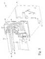
- FIG. 5is an exploded fragmentary perspective view of the power entry assembly of FIG. 1 .
- an electrical distribution system 10which generally includes an electrical distribution harness 12 , a power entry box 16 , a structural element 18 and a power entry assembly 20 .
- Structural element 18can be attached to, and supported by, a ceiling joist 22 via threaded rods 24 , fasteners 26 and hangers 28 ( FIGS. 2 and 3 ).
- Raceway 30can include AC and DC conductors (not shown), and other conductors or cables, which are passed through respective AC conduit 32 and DC conduit 34 to power entry box 16 .
- Power entry box 16is mounted to structural element 18 .
- Power entry box 16can have suitable internal elements such as bus bars, circuit boards, control elements, etc., to facilitate the routing and control of the AC and DC circuits from respective AC conduit 32 and DC conduit 34 .
- Electrical distribution harness 12can include harness conductors 36 which can comprise either AC and/or DC circuits, or other circuits such as data circuits.
- harness conductors 36can include three line conductors (12 gauge wire), one ground conductor (12 gauge wire) and one neutral conductor (10 gauge wire), and DC conductors as required which may typically include 14 or 12 gauge conductors.
- Electrical distribution harness 12includes at least one, and typically a plurality of, electrical distribution connectors 38 . Electrical terminals within electrical distribution connector 38 are connected to respective harness conductors 36 .
- Electrical distribution harness 12can include suitable barriers to separate AC terminals and AC harness conductors 36 , from DC terminals and DC harness conductors 36 , respectively.
- Electrical distribution harness 12can be mounted on either side of structural element 18 , but may typically be mounted one side. As shown in FIG. 2 , a variety of electrical elements such as a light 40 and a power post 42 can then easily be connected to electrical distribution harness 12 by connection to a respective electrical distribution connector 38 .
- Power entry assembly 20electrically interconnects electrical distribution connector 38 and power entry box 16 .
- Power entry assembly 20includes at least one conductor carrier 44 , 46 , and a housing 48 connected to at least one conductor carrier 44 , 46 .
- Housing 48includes a first orientation 50 relative to at least one conductor carrier 44 , 46 .
- a connector 52is connected to housing 48 at a second orientation 54 , where first orientation 50 is approximately 180° from second orientation 54 . That is, the terminals 56 ( FIG. 4 ) of connector 52 are faced in approximately the opposite direction as which at least one conductor carriers 44 , 46 enters housing 48 .
- Connector 52is connected to electrical distribution connector 38 .
- AC conductors 58 and DC conductors 60are connected to respective terminals 56 , which connect with respective terminals (not shown) in electrical distribution connector 38 , and the terminals of electrical distribution connector 38 are connected to respective harness conductors 36 .
- AC conductors 58 and DC conductors 60 , and corresponding conductor carriers 44 , 46can also connected to power entry box 16 .
- Conductor carrier 44can include a first outside texture 62 and conductor carrier 46 can include a second outside texture 64 , where first outside texture 62 is tactile discernibly different than second outside texture 64 .
- conductor carrier 44can be a relatively smooth oval cross-section and conductor carrier 46 can be a convoluted cross-section. Alternating current conductors 58 can be carried in conductor carrier 44 and direct current conductors 60 can be carried in conductor carrier 46 .
- Connector 52includes AC terminals 56 (lower as shown in FIGS. 4 and 5 ) connected to alternating current conductors 58 , and DC terminals 56 (upper as shown in FIGS. 4 and 5 ) connected to direct current conductors 60 , and connector 52 includes a connector barrier 66 separating the AC and DC terminals.
- Housing 48includes a housing barrier 68 separating alternating current conductors 58 and direct current conductors 60 . Housing 48 can also include a guide 70 adjacent connector 52 which helps facilitate the alignment of, and “blind” connection of, connector 52 relative to electrical distribution connector 38 , along with the texture of conductor carriers 44 , 46 and the orientation of connector 52 .
- the present inventiondiscloses a method of assembling power entry assembly 20 , comprising the steps of: connecting at least one conductor carrier 44 , 46 to housing 48 at first orientation 50 ; and attaching connector 52 to housing 48 at second orientation 54 , where first orientation 50 is approximately 180° from second orientation 54 .
Landscapes
- Distribution Board (AREA)
- Connection Or Junction Boxes (AREA)
Abstract
Description
Claims (12)
Priority Applications (2)
| Application Number | Priority Date | Filing Date | Title |
|---|---|---|---|
| US11/247,702US7264499B2 (en) | 2004-10-14 | 2005-10-11 | Power entry assembly for an electrical distribution system |
| US11/735,519US7518852B2 (en) | 2004-10-14 | 2007-04-16 | Power entry assembly for an electrical distribution system |
Applications Claiming Priority (2)
| Application Number | Priority Date | Filing Date | Title |
|---|---|---|---|
| US61873004P | 2004-10-14 | 2004-10-14 | |
| US11/247,702US7264499B2 (en) | 2004-10-14 | 2005-10-11 | Power entry assembly for an electrical distribution system |
Related Child Applications (1)
| Application Number | Title | Priority Date | Filing Date |
|---|---|---|---|
| US11/735,519ContinuationUS7518852B2 (en) | 2004-10-14 | 2007-04-16 | Power entry assembly for an electrical distribution system |
Publications (2)
| Publication Number | Publication Date |
|---|---|
| US20060084309A1 US20060084309A1 (en) | 2006-04-20 |
| US7264499B2true US7264499B2 (en) | 2007-09-04 |
Family
ID=36181352
Family Applications (2)
| Application Number | Title | Priority Date | Filing Date |
|---|---|---|---|
| US11/247,702Expired - Fee RelatedUS7264499B2 (en) | 2004-10-14 | 2005-10-11 | Power entry assembly for an electrical distribution system |
| US11/735,519Expired - Fee RelatedUS7518852B2 (en) | 2004-10-14 | 2007-04-16 | Power entry assembly for an electrical distribution system |
Family Applications After (1)
| Application Number | Title | Priority Date | Filing Date |
|---|---|---|---|
| US11/735,519Expired - Fee RelatedUS7518852B2 (en) | 2004-10-14 | 2007-04-16 | Power entry assembly for an electrical distribution system |
Country Status (1)
| Country | Link |
|---|---|
| US (2) | US7264499B2 (en) |
Cited By (7)
| Publication number | Priority date | Publication date | Assignee | Title |
|---|---|---|---|---|
| US20100184315A1 (en)* | 2006-06-12 | 2010-07-22 | Byrne Norman R | AC/DC raceway assembly |
| US20110088942A1 (en)* | 2006-06-12 | 2011-04-21 | Byrne Norman R | Dc receptacle |
| CN103794951A (en)* | 2012-10-30 | 2014-05-14 | 凡甲电子(苏州)有限公司 | Power connector and power connector combination |
| US9257823B2 (en) | 2013-05-31 | 2016-02-09 | Norman R. Byrne | Low voltage power receptacle for modular electrical systems |
| USD793343S1 (en) | 2014-05-30 | 2017-08-01 | Norman R. Byrne | Receptacle for modular wiring systems |
| US20180083383A1 (en)* | 2016-09-20 | 2018-03-22 | Yazaki Corporation | Connector, connector cover, and wire harness |
| US10644441B2 (en)* | 2017-05-31 | 2020-05-05 | Horizon Co., Ltd. | Cable |
Families Citing this family (9)
| Publication number | Priority date | Publication date | Assignee | Title |
|---|---|---|---|---|
| US7201593B2 (en)* | 2004-10-19 | 2007-04-10 | Pent Technologies, Inc. | Jumper assembly for an electrical distribution system |
| GB2441466B (en)* | 2005-05-24 | 2009-12-09 | Boston Retail Products Inc | System and method for distribution of electrical power |
| US20080280470A1 (en)* | 2007-05-11 | 2008-11-13 | Byrne Norman R | Modular electrical system including back-to-back receptacle configurations and capable of providing four wire circuitry |
| US7697268B2 (en)* | 2007-08-09 | 2010-04-13 | Haworth, Inc. | Modular electrical distribution system for a building |
| US8172588B2 (en)* | 2007-08-09 | 2012-05-08 | Haworth, Inc. | Modular electrical distribution system for a building |
| US8172589B2 (en)* | 2007-08-09 | 2012-05-08 | Haworth, Inc. | Modular electrical distribution system for a building |
| TWM379150U (en)* | 2009-11-16 | 2010-04-21 | Top 1 Green Dev Co Ltd | Transmission line structure that can eliminate negative magnetic field-induced electrical impedance |
| US20110309041A1 (en)* | 2010-05-27 | 2011-12-22 | Martin Amadio | Multi-view electronic displays in retail environments |
| US9071010B2 (en)* | 2012-09-30 | 2015-06-30 | Apple Inc. | Tight bend-radius cable structures and methods for making the same |
Citations (23)
| Publication number | Priority date | Publication date | Assignee | Title |
|---|---|---|---|---|
| US1967021A (en)* | 1931-07-07 | 1934-07-17 | Phillips Decker W | Safety electrical connecter |
| US3078433A (en)* | 1959-05-07 | 1963-02-19 | Res Engineering Co | Self-retaining electrical cable connector |
| US3551879A (en)* | 1968-12-20 | 1970-12-29 | Edmund M Waller Sr | Nonloosening electrical connector |
| US4583551A (en)* | 1984-11-19 | 1986-04-22 | Harold Pike | Multipolar medical electrode |
| US4784616A (en)* | 1985-07-23 | 1988-11-15 | Braun Aktiengesellschaft | Power supply device for an electrical appliance intended for personal use |
| US5080608A (en)* | 1990-06-05 | 1992-01-14 | Yarnton William W | Electrical plug connector |
| US5171159A (en)* | 1990-08-22 | 1992-12-15 | Byrne Norman R | Electrical interconnection assembly |
| US5199893A (en)* | 1991-07-22 | 1993-04-06 | Fussell Don L | Seismic connector with replaceable seal |
| US5605473A (en)* | 1995-09-05 | 1997-02-25 | Capetronic Computer Usa (Hk) Inc. | VGA loopback cable plug |
| US5957720A (en) | 1997-02-27 | 1999-09-28 | Pouyet S.A. | Female socket of modular-jack type with integrated connections |
| US6050840A (en)* | 1997-08-08 | 2000-04-18 | Coleman Cable Systems, Inc. | Electrical plug |
| US6179669B1 (en) | 1999-07-12 | 2001-01-30 | Thomas Shiaw-Cherng Chiang | Molded receptacle for a daisy chain power cord assembly |
| US6227886B1 (en)* | 1999-04-16 | 2001-05-08 | Avaya Technology Corp. | Snag-resistant patchcord plug latch and cover |
| US6305947B1 (en) | 1998-11-19 | 2001-10-23 | Berg Technology, Inc. | Angled coaxial connector module |
| US6336826B1 (en)* | 1998-12-17 | 2002-01-08 | Steelcase Development Corporation | Communications cabling system with twisted wire pairs |
| US6362418B1 (en) | 1999-08-25 | 2002-03-26 | Prestolite Wire Corporation | Self suppression wire for airbag ignitors and self suppression wire cable |
| US6457988B1 (en)* | 2000-12-21 | 2002-10-01 | Richard S. Eisen | Electrical connector |
| US6475032B1 (en)* | 2001-06-07 | 2002-11-05 | Houston Connector, Inc. | Geophysical connector |
| US6575761B1 (en) | 2000-08-30 | 2003-06-10 | Molex Incorporated | Coaxial connector module and method of fabricating same |
| US20030133259A1 (en) | 2002-01-16 | 2003-07-17 | Meyer Andreas A. | Compact vehicle drive module having improved thermal control |
| USD479508S1 (en) | 2002-12-20 | 2003-09-09 | Hon Hai Precision Ind. Co., Ltd. | Cable connector assembly |
| US20040009702A1 (en) | 1999-08-23 | 2004-01-15 | Patrick Potega | Interface apparatus for selectively connecting electrical devices |
| US6743042B2 (en) | 2002-04-15 | 2004-06-01 | Murr-Elektronik Gesellschaft mit beschränkter Haftung | Piercing contact clip |
Family Cites Families (24)
| Publication number | Priority date | Publication date | Assignee | Title |
|---|---|---|---|---|
| US3856981A (en)* | 1973-08-28 | 1974-12-24 | Westinghouse Electric Corp | Power panel arrangement |
| US4060294A (en)* | 1975-09-22 | 1977-11-29 | Haworth Mfg., Inc. | Wall panel with prewired power system |
| US4199206A (en)* | 1976-11-01 | 1980-04-22 | Haworth Mfg., Inc. | Wall panel with prewired power system |
| US4278834A (en)* | 1978-12-06 | 1981-07-14 | Westinghouse Electric Corp. | Versatile, electrified space dividing wall panel system |
| US4437716A (en)* | 1982-02-19 | 1984-03-20 | Westinghouse Electric Corp. | Electrified wall panel system |
| US4579403A (en)* | 1984-02-10 | 1986-04-01 | Byrne Norman R | Electrical junction assembly with adjustable connectors |
| US4593960A (en)* | 1985-03-27 | 1986-06-10 | Amp Incorporated | Power entry connector |
| US4688869A (en)* | 1985-12-12 | 1987-08-25 | Kelly Steven M | Modular electrical wiring track arrangement |
| US4959021A (en)* | 1988-04-12 | 1990-09-25 | Byrne Norman R | Pivotable power feed connector |
| US5214889A (en)* | 1990-01-18 | 1993-06-01 | Herman Miller, Inc. | Electrified wall panel system |
| US5041002A (en)* | 1990-04-17 | 1991-08-20 | Byrne Norman R | Extendable electrical junction assembly |
| US5096434A (en)* | 1990-08-22 | 1992-03-17 | Byrne Norman R | Electrical interconnection assembly |
| US5096433A (en)* | 1990-09-24 | 1992-03-17 | Westinghouse Electric Corp. | Electrified space dividing panel system |
| US5096431A (en)* | 1990-11-28 | 1992-03-17 | Byrne Norman R | Outlet receptable with rearrangeable terminals |
| US5087207A (en)* | 1990-12-11 | 1992-02-11 | Byrne Norman R | Circuit-selecting adapter for an electrical power receptacle |
| US5186640A (en)* | 1992-02-24 | 1993-02-16 | Group Dekko International | Wiring harness assembly |
| US5382179A (en)* | 1993-08-12 | 1995-01-17 | Burndy Corporation | Electrical connection system with mounting track |
| EP0806069B1 (en)* | 1995-01-25 | 2001-11-07 | Haworth, Inc. | Modular communication cabling arrangement |
| US5941720A (en)* | 1995-11-27 | 1999-08-24 | Byrne; Norman R. | Electrical interconnection assembly |
| US6027352A (en)* | 1996-12-11 | 2000-02-22 | Byrne; Norman R. | Electrical interconnection assembly with pivotal end connector |
| US5964610A (en)* | 1997-12-31 | 1999-10-12 | Dekko Engineering, Inc. | Reversible power entry |
| US6478602B1 (en)* | 2000-11-01 | 2002-11-12 | Pent Products, Inc. | Retainer clip for an electrical distribution assembly |
| US6910903B2 (en)* | 2002-09-05 | 2005-06-28 | Pent Technologies, Inc. | Receptacle mounting bracket attached to frame |
| US7144264B2 (en)* | 2003-11-10 | 2006-12-05 | Pent Technologies, Inc. | Add-on electrical distribution assembly |
- 2005
- 2005-10-11USUS11/247,702patent/US7264499B2/ennot_activeExpired - Fee Related
- 2007
- 2007-04-16USUS11/735,519patent/US7518852B2/ennot_activeExpired - Fee Related
Patent Citations (23)
| Publication number | Priority date | Publication date | Assignee | Title |
|---|---|---|---|---|
| US1967021A (en)* | 1931-07-07 | 1934-07-17 | Phillips Decker W | Safety electrical connecter |
| US3078433A (en)* | 1959-05-07 | 1963-02-19 | Res Engineering Co | Self-retaining electrical cable connector |
| US3551879A (en)* | 1968-12-20 | 1970-12-29 | Edmund M Waller Sr | Nonloosening electrical connector |
| US4583551A (en)* | 1984-11-19 | 1986-04-22 | Harold Pike | Multipolar medical electrode |
| US4784616A (en)* | 1985-07-23 | 1988-11-15 | Braun Aktiengesellschaft | Power supply device for an electrical appliance intended for personal use |
| US5080608A (en)* | 1990-06-05 | 1992-01-14 | Yarnton William W | Electrical plug connector |
| US5171159A (en)* | 1990-08-22 | 1992-12-15 | Byrne Norman R | Electrical interconnection assembly |
| US5199893A (en)* | 1991-07-22 | 1993-04-06 | Fussell Don L | Seismic connector with replaceable seal |
| US5605473A (en)* | 1995-09-05 | 1997-02-25 | Capetronic Computer Usa (Hk) Inc. | VGA loopback cable plug |
| US5957720A (en) | 1997-02-27 | 1999-09-28 | Pouyet S.A. | Female socket of modular-jack type with integrated connections |
| US6050840A (en)* | 1997-08-08 | 2000-04-18 | Coleman Cable Systems, Inc. | Electrical plug |
| US6305947B1 (en) | 1998-11-19 | 2001-10-23 | Berg Technology, Inc. | Angled coaxial connector module |
| US6336826B1 (en)* | 1998-12-17 | 2002-01-08 | Steelcase Development Corporation | Communications cabling system with twisted wire pairs |
| US6227886B1 (en)* | 1999-04-16 | 2001-05-08 | Avaya Technology Corp. | Snag-resistant patchcord plug latch and cover |
| US6179669B1 (en) | 1999-07-12 | 2001-01-30 | Thomas Shiaw-Cherng Chiang | Molded receptacle for a daisy chain power cord assembly |
| US20040009702A1 (en) | 1999-08-23 | 2004-01-15 | Patrick Potega | Interface apparatus for selectively connecting electrical devices |
| US6362418B1 (en) | 1999-08-25 | 2002-03-26 | Prestolite Wire Corporation | Self suppression wire for airbag ignitors and self suppression wire cable |
| US6575761B1 (en) | 2000-08-30 | 2003-06-10 | Molex Incorporated | Coaxial connector module and method of fabricating same |
| US6457988B1 (en)* | 2000-12-21 | 2002-10-01 | Richard S. Eisen | Electrical connector |
| US6475032B1 (en)* | 2001-06-07 | 2002-11-05 | Houston Connector, Inc. | Geophysical connector |
| US20030133259A1 (en) | 2002-01-16 | 2003-07-17 | Meyer Andreas A. | Compact vehicle drive module having improved thermal control |
| US6743042B2 (en) | 2002-04-15 | 2004-06-01 | Murr-Elektronik Gesellschaft mit beschränkter Haftung | Piercing contact clip |
| USD479508S1 (en) | 2002-12-20 | 2003-09-09 | Hon Hai Precision Ind. Co., Ltd. | Cable connector assembly |
Cited By (11)
| Publication number | Priority date | Publication date | Assignee | Title |
|---|---|---|---|---|
| US20100184315A1 (en)* | 2006-06-12 | 2010-07-22 | Byrne Norman R | AC/DC raceway assembly |
| US20110088942A1 (en)* | 2006-06-12 | 2011-04-21 | Byrne Norman R | Dc receptacle |
| US8585419B2 (en) | 2006-06-12 | 2013-11-19 | Norman R. Byrne | AC/DC raceway assembly |
| US8790126B2 (en)* | 2006-06-12 | 2014-07-29 | Norman R. Byrne | DC receptacle |
| CN103794951A (en)* | 2012-10-30 | 2014-05-14 | 凡甲电子(苏州)有限公司 | Power connector and power connector combination |
| US9257823B2 (en) | 2013-05-31 | 2016-02-09 | Norman R. Byrne | Low voltage power receptacle for modular electrical systems |
| USD793343S1 (en) | 2014-05-30 | 2017-08-01 | Norman R. Byrne | Receptacle for modular wiring systems |
| USD835587S1 (en) | 2014-05-30 | 2018-12-11 | Norman R. Byrne | Receptacle for modular wiring systems |
| US20180083383A1 (en)* | 2016-09-20 | 2018-03-22 | Yazaki Corporation | Connector, connector cover, and wire harness |
| US10249977B2 (en)* | 2016-09-20 | 2019-04-02 | Yazaki Corporation | Connector, connector cover, and wire harness |
| US10644441B2 (en)* | 2017-05-31 | 2020-05-05 | Horizon Co., Ltd. | Cable |
Also Published As
| Publication number | Publication date |
|---|---|
| US7518852B2 (en) | 2009-04-14 |
| US20070183122A1 (en) | 2007-08-09 |
| US20060084309A1 (en) | 2006-04-20 |
Similar Documents
| Publication | Publication Date | Title |
|---|---|---|
| US7518852B2 (en) | Power entry assembly for an electrical distribution system | |
| US6994585B2 (en) | Electrical wiring system | |
| US6575777B2 (en) | Partition wiring system | |
| US7654841B2 (en) | Pre-terminated outlet assembly for raceway systems | |
| US6774307B2 (en) | Through-wall electrical system | |
| CA1101114A (en) | Lighting and power system and connectors therefor | |
| US7557309B2 (en) | Data and power distribution system for an electrical busway | |
| US7470861B1 (en) | Power module for an electrical busway | |
| US5445539A (en) | Electrical wiring device for power control with low voltage input | |
| US8303330B2 (en) | Piercing connector for continuous flexible bus | |
| US6722918B2 (en) | Rail electrical connector system | |
| US20140216530A1 (en) | Photovoltaic mounting system with grounding bars and method of installing same | |
| US7201593B2 (en) | Jumper assembly for an electrical distribution system | |
| US7204696B1 (en) | Duplex receptacle | |
| US6948972B2 (en) | Overhead lighting splitter | |
| US6227903B1 (en) | Circuit connector block | |
| US20030194907A1 (en) | Modular receptacle coupler | |
| US20100084186A1 (en) | Fixture box enclosure | |
| KR100758922B1 (en) | Enhanced Electrical Junction Box | |
| JP4721162B2 (en) | Low-voltage branching device and method of accommodating fuse used in the same | |
| GB2337639A (en) | Electrical connector | |
| WO2010015830A1 (en) | An electrical fitting | |
| CA2424238C (en) | Self-locking junction box | |
| GB2374212A (en) | A consumer unit | |
| PL180868B1 (en) | Busbar system for electric cable distribution purpose and foer installation of the chan-l-wire lighting systems |
Legal Events
| Date | Code | Title | Description |
|---|---|---|---|
| AS | Assignment | Owner name:PENT TECHNOLOGIES, INC., INDIANA Free format text:ASSIGNMENT OF ASSIGNORS INTEREST;ASSIGNOR:KONDAS, SHAWN J.;REEL/FRAME:017095/0133 Effective date:20051006 | |
| AS | Assignment | Owner name:DYMAS FUNDING COMPANY, LLC, AS AGENT,ILLINOIS Free format text:SECURITY AGREEMENT;ASSIGNORS:PENT TECHNOLOGIES, INC.;DEKKO TECHNOLOGIES, LLC;REEL/FRAME:017971/0469 Effective date:20060720 Owner name:DYMAS FUNDING COMPANY, LLC, AS AGENT, ILLINOIS Free format text:SECURITY AGREEMENT;ASSIGNORS:PENT TECHNOLOGIES, INC.;DEKKO TECHNOLOGIES, LLC;REEL/FRAME:017971/0469 Effective date:20060720 | |
| STCF | Information on status: patent grant | Free format text:PATENTED CASE | |
| CC | Certificate of correction | ||
| AS | Assignment | Owner name:GROUP DEKKO, INC., INDIANA Free format text:MERGER;ASSIGNOR:PENT TECHNOLOGIES, INC.;REEL/FRAME:021936/0719 Effective date:20071227 Owner name:GROUP DEKKO, INC.,INDIANA Free format text:MERGER;ASSIGNOR:PENT TECHNOLOGIES, INC.;REEL/FRAME:021936/0719 Effective date:20071227 | |
| FPAY | Fee payment | Year of fee payment:4 | |
| AS | Assignment | Owner name:WELLS FARGO CAPITAL FINANCE, LLC, AS AGENT, ILLINO Free format text:SECURITY AGREEMENT;ASSIGNOR:GROUP DEKKO, INC.;REEL/FRAME:026503/0966 Effective date:20110624 | |
| FPAY | Fee payment | Year of fee payment:8 | |
| FEPP | Fee payment procedure | Free format text:MAINTENANCE FEE REMINDER MAILED (ORIGINAL EVENT CODE: REM.); ENTITY STATUS OF PATENT OWNER: LARGE ENTITY | |
| LAPS | Lapse for failure to pay maintenance fees | Free format text:PATENT EXPIRED FOR FAILURE TO PAY MAINTENANCE FEES (ORIGINAL EVENT CODE: EXP.); ENTITY STATUS OF PATENT OWNER: LARGE ENTITY | |
| STCH | Information on status: patent discontinuation | Free format text:PATENT EXPIRED DUE TO NONPAYMENT OF MAINTENANCE FEES UNDER 37 CFR 1.362 | |
| FP | Lapsed due to failure to pay maintenance fee | Effective date:20190904 |