US7264490B1 - Electronic equipment module with latching injector/ejector - Google Patents
Electronic equipment module with latching injector/ejectorDownload PDFInfo
- Publication number
- US7264490B1 US7264490B1US11/129,887US12988705AUS7264490B1US 7264490 B1US7264490 B1US 7264490B1US 12988705 AUS12988705 AUS 12988705AUS 7264490 B1US7264490 B1US 7264490B1
- Authority
- US
- United States
- Prior art keywords
- injector
- ejector
- panel
- latch member
- module
- Prior art date
- Legal status (The legal status is an assumption and is not a legal conclusion. Google has not performed a legal analysis and makes no representation as to the accuracy of the status listed.)
- Active, expires
Links
- 229910052751metalInorganic materials0.000claimsdescription7
- 239000002184metalSubstances0.000claimsdescription7
- 230000000717retained effectEffects0.000claimsdescription2
- 230000000712assemblyEffects0.000description8
- 238000000429assemblyMethods0.000description8
- 230000013011matingEffects0.000description6
- 230000007246mechanismEffects0.000description6
- 238000000034methodMethods0.000description6
- 230000015572biosynthetic processEffects0.000description5
- 238000005755formation reactionMethods0.000description5
- 238000003780insertionMethods0.000description4
- 230000037431insertionEffects0.000description4
- 238000009434installationMethods0.000description4
- 238000012986modificationMethods0.000description4
- 230000004048modificationEffects0.000description4
- 238000002347injectionMethods0.000description3
- 239000007924injectionSubstances0.000description3
- 238000007792additionMethods0.000description2
- 239000003990capacitorSubstances0.000description2
- 230000008878couplingEffects0.000description2
- 238000010168coupling processMethods0.000description2
- 238000005859coupling reactionMethods0.000description2
- 238000000605extractionMethods0.000description2
- 238000001746injection mouldingMethods0.000description2
- 230000001788irregularEffects0.000description2
- 238000003754machiningMethods0.000description2
- 239000000463materialSubstances0.000description2
- 238000003825pressingMethods0.000description2
- 239000004065semiconductorSubstances0.000description2
- 239000007787solidSubstances0.000description2
- 210000003813thumbAnatomy0.000description2
- 230000000007visual effectEffects0.000description2
- 241000237503PectinidaeSpecies0.000description1
- 229910000831SteelInorganic materials0.000description1
- 230000001154acute effectEffects0.000description1
- 239000000853adhesiveSubstances0.000description1
- 230000001070adhesive effectEffects0.000description1
- 229910052782aluminiumInorganic materials0.000description1
- XAGFODPZIPBFFR-UHFFFAOYSA-NaluminiumChemical compound[Al]XAGFODPZIPBFFR-UHFFFAOYSA-N0.000description1
- DMFGNRRURHSENX-UHFFFAOYSA-Nberyllium copperChemical compound[Be].[Cu]DMFGNRRURHSENX-UHFFFAOYSA-N0.000description1
- -1but not limited toSubstances0.000description1
- 238000005266castingMethods0.000description1
- 230000000295complement effectEffects0.000description1
- 239000004020conductorSubstances0.000description1
- 229920001971elastomerPolymers0.000description1
- 239000000806elastomerSubstances0.000description1
- 230000005670electromagnetic radiationEffects0.000description1
- 210000003811fingerAnatomy0.000description1
- 230000006870functionEffects0.000description1
- 239000011521glassSubstances0.000description1
- 230000010365information processingEffects0.000description1
- 230000000116mitigating effectEffects0.000description1
- 229920000642polymerPolymers0.000description1
- 229920000915polyvinyl chloridePolymers0.000description1
- 239000004800polyvinyl chlorideSubstances0.000description1
- 235000020637scallopNutrition0.000description1
- 230000007480spreadingEffects0.000description1
- 238000003892spreadingMethods0.000description1
- 229910001220stainless steelInorganic materials0.000description1
- 239000010935stainless steelSubstances0.000description1
- 239000010959steelSubstances0.000description1
Images


Classifications
- H—ELECTRICITY
- H01—ELECTRIC ELEMENTS
- H01R—ELECTRICALLY-CONDUCTIVE CONNECTIONS; STRUCTURAL ASSOCIATIONS OF A PLURALITY OF MUTUALLY-INSULATED ELECTRICAL CONNECTING ELEMENTS; COUPLING DEVICES; CURRENT COLLECTORS
- H01R13/00—Details of coupling devices of the kinds covered by groups H01R12/70 or H01R24/00 - H01R33/00
- H01R13/62—Means for facilitating engagement or disengagement of coupling parts or for holding them in engagement
- H01R13/629—Additional means for facilitating engagement or disengagement of coupling parts, e.g. aligning or guiding means, levers, gas pressure electrical locking indicators, manufacturing tolerances
- H01R13/62933—Comprising exclusively pivoting lever
Definitions
- This inventionrelates generally to electronic equipment, such as computers, and, more particularly, to apparatus used during insertion and extraction of circuit boards from electronic systems.
- a systemmay include number of circuit boards, each circuit board generally performing a specific function.
- Each circuit boardrequires multiple electrical connections, which are generally provided by two part multi-contact electrical connectors.
- One part of the connectoris mounted to the circuit board, while a mating part of the connector may be attached to another component of the system such as a rack, a chassis, a cable, or another circuit board (e.g., backplane circuit board).
- Successful mating of connector partsis needed for reliable electrical connections in the system.
- the systemmay include other modules, such as power supplies, disk drives, and fan tray assemblies.
- a number of mechanismsare known for injecting a module into a chassis or extracting a module from a chassis.
- Such mechanismsmay include levers pivotally coupled to the circuit board and arranged to engage projections formed on the chassis.
- Guide formationsmay be provided on the chassis to receive the module and to guide the module into position.
- the leversmay be arranged on the circuit board such that when the lever are actuated, the circuit board is provided with a biasing force that serves to move the circuit board toward the rear of the chassis. The biasing force is used to mate the parts of the electrical connector on the module with corresponding connector parts in the chassis.
- a large boardmay contain several multi-contact connectors, each connector containing several hundred individual contacts. Each contact requires the application of an insertion force to seat the contact. Thus, the total insertion force required to seat a large board may be 65 pounds or more.
- individual contactsare easily damaged if the mating connector parts are not properly aligned when they come into contact with each other. This problem is especially acute where large forces are required to mate the connector parts.
- Injection/extraction mechanismsconsume space near the front of a module.
- the size of some mechanismsmay require that the width and/or height of a slot for a given module be increased.
- Portions of a mechanisme.g., lever arms
- aperturesmust be provided in the module, chassis, and/or EMI seals to provide clearance for the levers and/or other hardware. Electromagnetic radiation may pass through the apertures, creating electromagnetic interference with the system.
- a moduleincludes a panel having a groove.
- An injector/ejectormay be coupled to the panel.
- the injector/ejectormay reside in the groove when the injector/ejector is in a closed position.
- a latch membermay be coupled to the panel. The latch member may selectively hold the injector/ejector in the closed position in the groove.
- a springe.g., a torsion spring
- a latch member for module injector/ejectorhas a body and a spring portion.
- the latch membermay be used to selectively latch and release the injector/ejector.
- the body of the latch membermay reside in a groove in a front panel of the module.
- the body of the latch membermay move within a limited range of motion in the groove.
- the walls of the groovemay guide the latch member.
- the spring portion of the latch memberresiliently urges the body of the latch member into engagement with the injector/ejector when the injector/ejector is placed in a closed position.
- the spring portionmay allow the body of the latch member to deflect to allow the injector/ejector to be released from the latch member. When the user lets go of the latch member, the spring portion may return the body of the latch member to a rest position.
- a latch member for a module injector/ejectoris attached to a panel of the module using a snap-on arrangement.
- the latch membermay include one or more protrusions that snap into apertures in the panel.
- one or more of the aperturesis slotted to allow movement of a portion of the latch member to release the latch member from the injector/ejector.
- a front panel for a modulemay be made of a flat sheet (e.g., sheet metal).
- the flat sheetmay have a fold that defines the groove.
- the groovemay receive an injector/ejector for the module.
- the panelmay have flanges along the outer edge of the panel that extend in the same direction as the fold.
- a module assemblyincludes a chassis that houses some or all of the components of the module assembly.
- An EMI gasketmay be provided between the chassis and a front panel of the module assembly.
- the chassis, front panel, and EMI gasketmay include slots that allow for passage of an injector/ejector for the module assembly.
- the chassis, front panel, and EMI gasket, and injector/ejectormay combine to form an EMI enclosure for components in the module.
- the module assemblyincludes a pair of injector/ejectors that each engages one side of a rack.
- FIG. 1depicts a fan tray assembly including an injector/ejector.
- FIG. 2is a front view of a front panel coupled to an injector/ejector in a closed position.
- FIG. 3is a cross sectional view of a front panel coupled to an injector/ejector in a closed position taken along lines 3 - 3 of FIG. 2 .
- FIG. 4is an exploded view of a fan tray assembly.
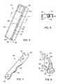
- FIG. 5depicts a front panel for a fan tray assembly.
- FIG. 6is a cross sectional view of a front panel taken substantially along lines 6 - 6 of FIG. 5 .
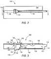
- FIG. 7depicts an injector/ejector.
- FIG. 8depicts a latch member for an injector/ejector system.
- FIG. 9depicts a fan tray assembly including a latching injector/ejector before installation of the circuit module in a rack.
- FIG. 10depicts a fan tray assembly during installation of the fan tray assembly in a rack.
- FIG. 11depicts a fan tray assembly when the fan tray assembly is in an installed position.
- FIG. 12depicts a fan tray assembly after release of a latching member.
- FIG. 13depicts a computer system including module assemblies with injector/ejector pairs in grooves.
- the following descriptiongenerally relates to apparatus and methods for installing and removing modules from computer systems. Such systems and methods may be used in a variety of applications.
- a non-exhaustive list of such applicationsincludes: telecommunications network server systems; e-commerce web server systems; LAN application and file server systems; personal computer systems; and remote vehicle control systems.
- moduleincludes any modular unit or subsystem. Examples of a module include, but are not limited to, a printed circuit board assembly, an information-processing cartridge, a fan tray assembly, a disk drive, a memory module, a power supply, or a combination thereof. In certain embodiments, a module may include multiple circuit boards (e.g., a mezzanine card mounted to a main circuit board). In certain embodiments, components of a module may be housed in an enclosure.
- circuit moduleincludes any module that includes or carries elements of an electrical circuit, electrical components (including, but not limited to, semiconductor devices, resistors, capacitors, relays, switches, and connectors), or conductors (e.g., wires, traces).
- circuit boardincludes any circuit module that carries one or more other circuit modules or components.
- circuit boardincludes, but is not limited to, a printed circuit board made of epoxy-glass and metal layers.
- componentincludes any element of system, including, but not limited to, a printed circuit board, a semiconductor device, a resistor, a capacitor, a power supply, or a disk drive.
- a computer systemmay include components installed in a chassis or rack assembly.
- rackincludes any structure that supports or houses one or more elements of a computer system (e.g., electronic modules).
- a componentmay be supported in a rack by various structures including, but not limited to, slides, rails, a shelf, or a bottom of a rack.
- insertsor “chassis” includes any structure that supports or houses one or more elements of a module or modules.
- a moduleis a fan tray assembly.
- FIG. 1depicts fan tray assembly 100 .
- Fan tray assembly 100may include chassis 102 , front panel 104 , and injector/ejector 106 .
- Injector/ejector 106may be pivotally connected to front panel 104 .
- Injector/ejector 106may be operated to couple and decouple fan tray assembly 100 to and from a rack.
- injector/ejectorsmay be provided on other sides of a module (e.g., rear, top, or bottom).
- injector/ejectorincludes any element that may be used to inject a component into a system, eject a component from a system, or both.
- to “inject”generally means to couple a component to a system or another component.
- “Injecting” a circuit boardmay include, but is not limited to, advancing a circuit board to couple a connector part on the circuit board with a mating connector part on another component (e.g., a backplane).
- to “eject”generally means to decouple a component from a system or another component.
- “Ejecting” a circuit boardmay include, but is not limited to, withdrawing a circuit board to decouple a connector part on the circuit board from a mating connector part on another component (e.g., a backplane).
- injector/ejector devicesinclude, but are not limited to, levers, screws, rods, cams, hooks, or pins.
- Injector/ejector 106may include handle 108 , inject portion 110 , and eject portion 112 . Inject portion 110 and eject portion 112 may move within chassis slot 114 in chassis 102 when injector/ejector 106 is actuated using handle 108 . As further described herein, injector/ejector 106 may be position to selectively engage inject portion 110 and eject portion 112 on a fixed structure on a rack (e.g., a side rail) to couple fan tray assembly 100 with the rack and decouple the fan tray assembly from the rack.
- a racke.g., a side rail
- an injector/ejectormay in some embodiments be provided on only one side (e.g., top, bottom, left side, or right side) of a module. In other embodiments, injector/ejectors may be provided on each of the opposing sides of a module (e.g., top and bottom). In still other embodiments, an injector/ejector may be provided in other locations of a module (e.g., the center of a module).
- Front panel 104may include groove 116 .
- Injector/ejector 106may reside in groove 116 when injector/ejector 106 is placed in a closed position (e.g., after injection of fan tray assembly 100 ).
- “groove”generally refers to any groove, channel, recess, hollow, or depression in a surface.
- groove 116may in some embodiments extend across front panel 104 . In other embodiments, a groove may extend over only a portion of a front panel.
- a groovemay have various regular or irregular cross sections.
- Fan tray assembly 100may include latch member 118 .
- Latch member 118may be movably coupled to front panel 104 .
- Latch member 118may engage notch 120 on injector/ejector 106 to hold injector/ejector 106 in a closed position in groove 116 of front panel 104 .
- membermay include a single member or multiple members. Portions of a member may be straight and/or curved, flexible and/or rigid, or a combination thereof.
- a latch membermay include various elements for selectively holding and releasing an injector/ejector. Suitable latch types include, but are not limited to, a slider, a push knob latch, coil spring latch, or touch latch.
- Fan tray assembly 100may include torsion spring 122 .
- Torsion spring 122may be coupled between injector/ejector and front panel 104 . Torsion spring 122 may bias handle 108 of injector/ejector 106 away from front panel 104 . Injector/ejector 106 may rotate to an open position (e.g., with handle 108 away from front panel 104 ) when latch member 118 is moved out of engagement with injector/ejector 106 .
- FIG. 2is a front view of fan tray assembly 100 .
- FIG. 3is a cross sectional view of fan tray assembly 100 showing front panel 104 , injector/ejector 106 , and latch member 118 .
- Injector/ejector 106may be coupled to front panel 104 .
- Rear wall 126 of front panel 104may include hole 128 and slot 130 for receiving latch member 118 .
- Hole 128 and slot 130may have various shapes and sizes, including, but not limited to, round, square, diamond-shaped, hexagonal, or hexalobular.
- Latch member 118may be attached to front panel 104 using a snap-on arrangement.
- Latch member 118may include mounting protrusions (e.g., tabs, legs, or pins) that couple in apertures (e.g., holes, slots) of front panel 104 .
- latch member 118may include latch body 132 , release portion 134 , engaging portion 136 , spring portion 138 , legs 140 , 142 , and projections 144 , 146 .
- Release portion 134may be operated by a user (e.g., by pressing with the user's thumb) to manually release latch member 118 from engagement with injector/ejector 106 .
- Projections 144 , 146may extend in a transverse direction relative to legs 140 , 142 .
- Leg 140may include lead-in taper 148 to facilitate engagement of leg 140 in hole 128 .
- leg 142may include a taper.
- latch memberis depicted in FIGS. 2-3 as a snap-on member, a latch member may in other embodiments be attached to a module using other suitable arrangements, such as a screw, a clip, a bolt, a rivet, or adhesive.
- spring portionincludes any resiliently deformable (e.g., bendable) member or combination of members, and includes, but is not limited to, a beam, bar, rod, coil, or combination of such elements.
- spring portion 138may in some embodiments be a relatively thin and flexible section of leg 140 that allows the distal end of leg 140 to deflect relative to latch body 132 .
- both legsmay include flexible portions.
- latch member 118is formed as a single member (e.g., by injection molding). Forming a latch member as a single part may reduce a cost of producing a latch system, as compared with a latch system produced from separate parts. In other embodiments, however, a latch member may be a combination of separate parts.
- a springsuch as a torsion spring, coil spring, or elastomeric member, may be provided as a separate component of the latch member.
- legs 140 , 142may be brought toward each other (e.g., by squeezing the sides of the latch member) such that projections 144 , 146 align with hole 128 and slot 130 .
- Legs 140 , 142may be inserted into hole 128 and slot 130 , respectively.
- spring portion 138may return latch member 118 to a free state, spreading legs 140 , 142 away from each other.
- Projections 144 , 146may overlap rear wall 126 of front panel 104 such that latch member 118 is retained in groove 116 . As shown in FIG.
- slot 130may allow release portion 134 to be moved laterally such that latch member 118 is disengaged from notch 120 of injector/ejector 106 .
- Projection 146may be of sufficient length to maintain latch member 118 in groove even when latch member 118 is positioned to release injector/ejector 106 .
- Latch body 132may reside in groove 116 behind forward edge 156 of front panel 104 when latch member 118 is installed on front panel 104 .
- handle 108 of injector/ejector 106may also be behind the forward edge 156 of front panel 104 .
- Including a groove on a front panel of a modulemay allow the module to have a low profile at the front of the module.
- release portion 134 of latch member 118may protrude beyond forward edge 156 of front panel 104 .
- a release portion for a latch membermay be recessed behind the forward edge of the module.
- FIG. 4is an exploded view of fan tray assembly 100 .
- Chassis 102may include chassis body 158 and cover 160 .
- Chassis body 158may include right panel 162 , top panel 164 , bottom panel 166 , and rear panel 168 .
- Cover 160may include left panel 170 .
- Fasteners 172may be used to attach cover 160 to chassis body 158 .
- Right panel 162 of chassis body 158 and left panel 170 of covermay include vents 174 . Vents 174 may allow for passage of air through fan tray assembly 100 .
- fansare not shown in FIG. 4 . It will be understood, however, that fans may be provided inside chassis 102 adjacent to each of vents 174 .
- Fan tray assembly 100may include fasteners 176 .
- Fasteners 176may be used to attach front panel 104 to chassis body 158 and cover 160 .
- Injector/ejector 106may be coupled to front panel 104 using pin 177 .
- Front panel 104may include indicator panel 178 .
- Indicator panel 178may include status visual indicators 180 (e.g., light emitting diodes) that provide visual status regarding the operation of the fan tray assembly 100 .
- EMI gasket 182may be provided between chassis 102 and front panel 104 .
- EMI gasketmay include gasket slot 183 .
- Gasket slot 183may allow for passage of injector/ejector 106 .
- Gasket slotmay be slightly larger than the thickness of the injector/ejector.
- EMI gasket 182may be formed of beryllium copper, conductive elastomer, or various other materials that provide electromagnetic shielding.
- EMI gasket 182may contain electromagnetic energy generated by fans in fan tray assembly 100 . It will be understood that EMI gasket may be used to contain electromagnetic energy produced by other components on a module such as processors or disk drive motors.
- a gasket for a modulemay shield components in the module from electromagnetic energy produced by components surrounding the module.
- FIG. 5depicts front panel 104 .
- Front panel 104may be formed from sheet metal stock. Producing a front panel from sheet metal stock may allow the front panel to be made as a single, low cost part. Nevertheless, a front panel may in other embodiments be produced by other methods, such machining the panel from stock or injection molding.
- Front panel 104may include front walls 184 and fold 186 .
- Fold 186may include rear wall 126 .
- Rear wall end slot 190may allow clearance for injector/ejector 106 .
- Pivot holes 192may be provided for pinning injector/ejector 106 to front panel 104 .
- FIG. 6depicts a cross sectional view of front panel 104 .
- the interior surfaces of fold 186may define groove 116 .
- Inside surfaces of fold 186may have various cross sections, such as U-shaped, square, V-shaped, or arcuate.
- fold 186may have a uniform cross section over the length of front panel 104 .
- the depth of groove 116may vary over the length of front panel 104 .
- Front panel 104may include flanges 194 around the edges of front wall 184 .
- flangegenerally refers to any projecting rim, lip, or wall.
- a flangemay have any of various regular or irregular cross sections.
- a flangemay be solid or not solid (e.g., perforated).
- flangesextend toward the rear of front panel 104 coextensively with rear wall 126 of fold 186 .
- flanges 194may be shorter or longer than fold 186 .
- flanges 194may in some embodiments be proximate to the ends of fold 186 .
- Flanges 194may partially fill apertures between front wall 184 of front panel 104 and chassis 102 , thereby containing radiated emissions from components within the module.
- FIG. 7depicts an injector/ejector 106 .
- Injector/ejector 106may be produced folding sheet metal into a flat, U-shaped member. Producing an injector/ejector from sheet metal stock may allow the injector/ejector to be made as a single, low cost part.
- a flat, relatively thin injector/ejectormay reduce the size of apertures needed in a front panel and/or chassis to operate the injector/ejector, thereby mitigating EMI.
- an injector/ejectormay be machined, molded, or made using other suitable methods.
- Handle 108may include scallops 196 to facilitate gripping by a user.
- chassis slot 114may combine to form an opening large enough to allow for rotation of injector/ejector to engage and apply forces to a rack structure, but without creating large apertures in the fan tray assembly enclosure (see FIG. 1 ).
- flanges 194may fill gaps between EMI gasket 182 near the ends of fold 186 .
- Chassis 102 , front panel 104 , EMI gasket 182 , and injector/ejector 106may combine to form an EMI enclosure for the module.
- FIG. 8depicts latch member 118 .
- Latch member 118may include connecting portion 198 .
- Connecting portion 198may be a necked down region that connects spring portion 138 and leg 140 to latch body 132 .
- Latch membermay be produced from various suitable materials, including, but not limited to, stainless steel, aluminum, or a polymer (e.g., polyvinyl chloride, ABS).
- latch member 118is a produced as a unitary piece (e.g., injection molded).
- latch member 118may include multiple elements.
- latch member 118may include a body and two or more rigid legs connected by a steel spring.
- Latch member 118may be produced by other methods, such as machining, stamping, or casting.
- latch members 118may engage injector/ejector 106 to selectively inhibit or allow movement of one or more elements.
- engageor “engaging” includes any condition in which one element engages (e.g., contacts) another element during operation or use of an apparatus.
- engaging portion 136 of latch member 118may engage in notch 120 in injector/ejector 106 , as shown in FIG. 3 . Engagement of latch member 118 of engaging portions 136 in notches 120 may inhibit injector/ejector 106 from being rotated away from front panel 104 .
- Latch member 118may be disengaged from injector/ejector 106 , allowing injector/ejector 106 to rotate with respect to front panel 104 . While release portion 134 in the embodiment shown are manually actuated, in other embodiments the releases may automatically actuated. Releases may be actuated by hand or using various devices, including, but not limited to, hand tools power tools, or solenoid devices.
- latch member 118translates in a lateral direction relative to front panel 104 . It will be understood, however, that in other embodiments, the motion of a latch member may take various other forms relative to a module. For example, a latch member may translate from front to back with respect to the module, rotate with respect to the module, or a combination of both.
- FIGS. 9-12depict injector/ejector 106 on fan tray assembly 100 during installation of fan tray assembly 100 , and removal of fan tray assembly 100 from, rack 204 . It will be understood that in some embodiments an injector/ejector and latch device on the other side of the module assembly may operate in a similar manner.
- injector/ejector 106may be biased into an open position by torsion springs 122 (shown in FIG. 3 ).
- torsion springs 122shown in FIG. 3 .
- a usermay advance fan tray assembly 100 into rack 204 until inject portions 110 of injector/ejector 106 are past rack formations 206 on rack 204 .
- the usermay then rotate injector/ejector 106 in the direction of arrow I such that inject portions 110 engage rack formations 206 .
- Engagement of inject portions 110 with rack formations 206may force fan tray assembly 100 forward to inject fan tray assembly 100 into rack 204 .
- taper 207 on injector/ejector 106may slide across complementary taper 208 on latch member 118 .
- Latch member 118may deflect in the direction of arrow D.
- injector/ejector 106may be rotated until fan tray assembly 100 is fully inserted into rack 204 . Injector/ejector 106 may reach a closed position. Spring portion 138 of latch member 118 may urge latch member 118 in the direction of arrow L such that engaging portion 136 of latch member 118 enters into notch 120 on injector/ejector 106 .
- a usermay actuate release portion 134 by applying pressure to the release portion with a thumb or finger.
- Latch member 118may move in the direction of arrow R.
- injector/ejector 106may rotate under the spring force of torsion spring 122 (shown in FIG. 3 ) in the direction of arrow E.
- Eject portion 112 of injector/ejector 106may engage rack formation 206 on rack 204 .
- a usermay grasp injector/ejector 106 and continue rotation in the direction of arrow E. Injector/ejector 106 may be actuated to force fan tray assembly 100 out of rack 204 .
- FIG. 13depicts computer system 210 including module assemblies 212 in rack enclosure 214 .
- Module assemblies 212may include left and right injector/ejectors 106 coupled to front panels 104 .
- Latch members 118may be provided to latch injector/ejectors 106 in a closed position in grooves 116 .
- connector parts on a rear side of module assemblies 212may couple with mating connector parts in rack enclosure 214 (e.g., backplane connectors) when injector/ejectors 106 are operated to inject module assembly 212 .
- a combination of rack enclosure 214 , front panels 104 , and injector/ejectors 106may form an enclosure for containing EMI.
- one or more EMI gasketsmay be provided to seal apertures between rack enclosure 214 and module assemblies 212 .
- injector/ejectors 106When injector/ejectors 106 are in a closed position in grooves 116 , injector/ejectors 106 may have a low profile on front side of module assemblies 106 .
- injector/ejectors 106may be flush with front edges of front panels 104 or recessed behind the front edges of front panels 104 .
- a covermay be attached (e.g., hinged) to rack enclosure 214 such that the cover contacts, or is in close proximity to, front panels 104 .
- a latch membermay be coupled to a front panel by directly attaching the latch member to the front panel, or by mounting the latch member to a bracket attached to the front panel.
Landscapes
- Shielding Devices Or Components To Electric Or Magnetic Fields (AREA)
Abstract
Description
1. Field of the Invention
This invention relates generally to electronic equipment, such as computers, and, more particularly, to apparatus used during insertion and extraction of circuit boards from electronic systems.
2. Background Information
Electronic systems such as computers are typically constructed in a modular fashion. For example, a system may include number of circuit boards, each circuit board generally performing a specific function. Each circuit board requires multiple electrical connections, which are generally provided by two part multi-contact electrical connectors. One part of the connector is mounted to the circuit board, while a mating part of the connector may be attached to another component of the system such as a rack, a chassis, a cable, or another circuit board (e.g., backplane circuit board). Successful mating of connector parts is needed for reliable electrical connections in the system. The system may include other modules, such as power supplies, disk drives, and fan tray assemblies.
A number of mechanisms are known for injecting a module into a chassis or extracting a module from a chassis. Such mechanisms may include levers pivotally coupled to the circuit board and arranged to engage projections formed on the chassis. Guide formations may be provided on the chassis to receive the module and to guide the module into position. The levers may be arranged on the circuit board such that when the lever are actuated, the circuit board is provided with a biasing force that serves to move the circuit board toward the rear of the chassis. The biasing force is used to mate the parts of the electrical connector on the module with corresponding connector parts in the chassis.
For circuit boards with connectors having a relatively large number of pins, large insertion forces may be required to mate the connector parts. For example, a large board may contain several multi-contact connectors, each connector containing several hundred individual contacts. Each contact requires the application of an insertion force to seat the contact. Thus, the total insertion force required to seat a large board may be 65 pounds or more. Moreover, individual contacts are easily damaged if the mating connector parts are not properly aligned when they come into contact with each other. This problem is especially acute where large forces are required to mate the connector parts.
Injection/extraction mechanisms, and the mounting hardware associated with the mechanisms, consume space near the front of a module. The size of some mechanisms may require that the width and/or height of a slot for a given module be increased. Portions of a mechanism (e.g., lever arms) may also take up space outside a front panel of a module. In addition, apertures must be provided in the module, chassis, and/or EMI seals to provide clearance for the levers and/or other hardware. Electromagnetic radiation may pass through the apertures, creating electromagnetic interference with the system.
Various embodiments of apparatus and methods for injecting and ejecting modules (e.g., circuit modules, fan tray assemblies) are disclosed. In an embodiment, a module includes a panel having a groove. An injector/ejector may be coupled to the panel. The injector/ejector may reside in the groove when the injector/ejector is in a closed position. A latch member may be coupled to the panel. The latch member may selectively hold the injector/ejector in the closed position in the groove. In some embodiments, a spring (e.g., a torsion spring) is provided to urge the injector/ejector into an open position when the latch member moved out of engagement with the injector/ejector.
In an embodiment, a latch member for module injector/ejector has a body and a spring portion. The latch member may be used to selectively latch and release the injector/ejector. The body of the latch member may reside in a groove in a front panel of the module. The body of the latch member may move within a limited range of motion in the groove. The walls of the groove may guide the latch member. In some embodiments, the spring portion of the latch member resiliently urges the body of the latch member into engagement with the injector/ejector when the injector/ejector is placed in a closed position. The spring portion may allow the body of the latch member to deflect to allow the injector/ejector to be released from the latch member. When the user lets go of the latch member, the spring portion may return the body of the latch member to a rest position.
In an embodiment, a latch member for a module injector/ejector is attached to a panel of the module using a snap-on arrangement. The latch member may include one or more protrusions that snap into apertures in the panel. In some embodiments, one or more of the apertures is slotted to allow movement of a portion of the latch member to release the latch member from the injector/ejector.
In an embodiment, a front panel for a module may be made of a flat sheet (e.g., sheet metal). The flat sheet may have a fold that defines the groove. The groove may receive an injector/ejector for the module. In some embodiments, the panel may have flanges along the outer edge of the panel that extend in the same direction as the fold.
In an embodiment, a module assembly includes a chassis that houses some or all of the components of the module assembly. An EMI gasket may be provided between the chassis and a front panel of the module assembly. The chassis, front panel, and EMI gasket may include slots that allow for passage of an injector/ejector for the module assembly. The chassis, front panel, and EMI gasket, and injector/ejector may combine to form an EMI enclosure for components in the module. In one embodiment, the module assembly includes a pair of injector/ejectors that each engages one side of a rack.
Other aspects of the invention will become apparent upon reading the following detailed description and upon reference to the accompanying drawings in which:
While the invention is susceptible to various modifications and alternative forms, specific embodiments thereof are shown by way of example in the drawings and will herein be described in detail. It should be understood, however, that the drawings and description thereto are not intended to limit the invention to the particular form disclosed, but, on the contrary, the invention is to cover all modifications, equivalents, and alternatives falling with the spirit and scope of the present invention as defined by the appended claims.
The following description generally relates to apparatus and methods for installing and removing modules from computer systems. Such systems and methods may be used in a variety of applications. A non-exhaustive list of such applications includes: telecommunications network server systems; e-commerce web server systems; LAN application and file server systems; personal computer systems; and remote vehicle control systems.
As used herein, “module” includes any modular unit or subsystem. Examples of a module include, but are not limited to, a printed circuit board assembly, an information-processing cartridge, a fan tray assembly, a disk drive, a memory module, a power supply, or a combination thereof. In certain embodiments, a module may include multiple circuit boards (e.g., a mezzanine card mounted to a main circuit board). In certain embodiments, components of a module may be housed in an enclosure.
As used herein, “circuit module” includes any module that includes or carries elements of an electrical circuit, electrical components (including, but not limited to, semiconductor devices, resistors, capacitors, relays, switches, and connectors), or conductors (e.g., wires, traces). As used herein, “circuit board” includes any circuit module that carries one or more other circuit modules or components. “Circuit board” includes, but is not limited to, a printed circuit board made of epoxy-glass and metal layers. As used herein, “component” includes any element of system, including, but not limited to, a printed circuit board, a semiconductor device, a resistor, a capacitor, a power supply, or a disk drive.
A computer system may include components installed in a chassis or rack assembly. As used herein, “rack” includes any structure that supports or houses one or more elements of a computer system (e.g., electronic modules). A component may be supported in a rack by various structures including, but not limited to, slides, rails, a shelf, or a bottom of a rack. As used herein, “enclosure” or “chassis” includes any structure that supports or houses one or more elements of a module or modules.
In an embodiment, a module is a fan tray assembly.FIG. 1 depictsfan tray assembly 100.Fan tray assembly 100 may includechassis 102,front panel 104, and injector/ejector 106. Injector/ejector 106 may be pivotally connected tofront panel 104. Injector/ejector 106 may be operated to couple and decouplefan tray assembly 100 to and from a rack. In other embodiments, injector/ejectors may be provided on other sides of a module (e.g., rear, top, or bottom).
As used herein, “injector/ejector” includes any element that may be used to inject a component into a system, eject a component from a system, or both. As used herein, to “inject” generally means to couple a component to a system or another component. “Injecting” a circuit board may include, but is not limited to, advancing a circuit board to couple a connector part on the circuit board with a mating connector part on another component (e.g., a backplane). As used herein, to “eject” generally means to decouple a component from a system or another component. “Ejecting” a circuit board may include, but is not limited to, withdrawing a circuit board to decouple a connector part on the circuit board from a mating connector part on another component (e.g., a backplane). Examples of injector/ejector devices include, but are not limited to, levers, screws, rods, cams, hooks, or pins.
Injector/ejector 106 may include handle108, injectportion 110, and ejectportion 112. Injectportion 110 and ejectportion 112 may move withinchassis slot 114 inchassis 102 when injector/ejector 106 is actuated usinghandle 108. As further described herein, injector/ejector 106 may be position to selectively engage injectportion 110 and ejectportion 112 on a fixed structure on a rack (e.g., a side rail) to couplefan tray assembly 100 with the rack and decouple the fan tray assembly from the rack.
As shown inFIG. 1 , an injector/ejector may in some embodiments be provided on only one side (e.g., top, bottom, left side, or right side) of a module. In other embodiments, injector/ejectors may be provided on each of the opposing sides of a module (e.g., top and bottom). In still other embodiments, an injector/ejector may be provided in other locations of a module (e.g., the center of a module).
As used herein, “spring portion” includes any resiliently deformable (e.g., bendable) member or combination of members, and includes, but is not limited to, a beam, bar, rod, coil, or combination of such elements. As shown inFIG. 3 ,spring portion 138 may in some embodiments be a relatively thin and flexible section ofleg 140 that allows the distal end ofleg 140 to deflect relative to latchbody 132. In other embodiments, both legs may include flexible portions. In an embodiment,latch member 118 is formed as a single member (e.g., by injection molding). Forming a latch member as a single part may reduce a cost of producing a latch system, as compared with a latch system produced from separate parts. In other embodiments, however, a latch member may be a combination of separate parts. For example, a spring, such as a torsion spring, coil spring, or elastomeric member, may be provided as a separate component of the latch member.
To installlatch member 118 onfront panel 104,legs projections hole 128 andslot 130.Legs hole 128 andslot 130, respectively. Afterprojections hole 128 andslot 130,spring portion 138 may returnlatch member 118 to a free state, spreadinglegs Projections rear wall 126 offront panel 104 such thatlatch member 118 is retained ingroove 116. As shown inFIG. 3 ,slot 130 may allowrelease portion 134 to be moved laterally such thatlatch member 118 is disengaged fromnotch 120 of injector/ejector 106.Projection 146 may be of sufficient length to maintainlatch member 118 in groove even whenlatch member 118 is positioned to release injector/ejector 106.
Referring again toFIGS. 4 and 5 ,chassis slot 114,gasket slot 183, and rearwall end slot 190 offront panel 104 may combine to form an opening large enough to allow for rotation of injector/ejector to engage and apply forces to a rack structure, but without creating large apertures in the fan tray assembly enclosure (seeFIG. 1 ). In addition,flanges 194 may fill gaps betweenEMI gasket 182 near the ends offold 186.Chassis 102,front panel 104,EMI gasket 182, and injector/ejector 106 may combine to form an EMI enclosure for the module.
As described above,latch members 118 may engage injector/ejector 106 to selectively inhibit or allow movement of one or more elements. As used herein, “engage” or “engaging” includes any condition in which one element engages (e.g., contacts) another element during operation or use of an apparatus.
When injector/ejector 106 is placed in a closed position, engagingportion 136 oflatch member 118 may engage innotch 120 in injector/ejector 106, as shown inFIG. 3 . Engagement oflatch member 118 of engagingportions 136 innotches 120 may inhibit injector/ejector 106 from being rotated away fromfront panel 104.
In the embodiment shown inFIGS. 2-3 ,latch member 118 translates in a lateral direction relative tofront panel 104. It will be understood, however, that in other embodiments, the motion of a latch member may take various other forms relative to a module. For example, a latch member may translate from front to back with respect to the module, rotate with respect to the module, or a combination of both.
As shown inFIG. 9 , prior to installation offan tray assembly 100, injector/ejector 106 may be biased into an open position by torsion springs122 (shown inFIG. 3 ). Referring toFIG. 10 , to injectfan tray assembly 100 intorack 204, a user may advancefan tray assembly 100 intorack 204 until injectportions 110 of injector/ejector 106 arepast rack formations 206 onrack 204. The user may then rotate injector/ejector 106 in the direction of arrow I such that injectportions 110 engagerack formations 206. Engagement of injectportions 110 withrack formations 206 may forcefan tray assembly 100 forward to injectfan tray assembly 100 intorack 204. As injector/ejector 106 are rotated in the direction of arrow I, taper207 on injector/ejector 106 may slide acrosscomplementary taper 208 onlatch member 118.Latch member 118 may deflect in the direction of arrow D.
Referring toFIG. 11 , injector/ejector 106 may be rotated untilfan tray assembly 100 is fully inserted intorack 204. Injector/ejector 106 may reach a closed position.Spring portion 138 oflatch member 118 may urgelatch member 118 in the direction of arrow L such that engagingportion 136 oflatch member 118 enters intonotch 120 on injector/ejector 106.
Referring toFIG. 12 , to removefan tray assembly 100 fromrack 204, a user may actuaterelease portion 134 by applying pressure to the release portion with a thumb or finger.Latch member 118 may move in the direction of arrow R. When engagingportion 136 oflatch member 118 clearsnotch 120, injector/ejector 106 may rotate under the spring force of torsion spring122 (shown inFIG. 3 ) in the direction of arrowE. Eject portion 112 of injector/ejector 106 may engagerack formation 206 onrack 204. A user may grasp injector/ejector 106 and continue rotation in the direction of arrow E. Injector/ejector 106 may be actuated to forcefan tray assembly 100 out ofrack 204.
As used herein, “coupled” includes a direct coupling or an indirect coupling (e.g., with one or more intervening elements) unless expressly stated otherwise. For example, a latch member may be coupled to a front panel by directly attaching the latch member to the front panel, or by mounting the latch member to a bracket attached to the front panel.
While the present invention has been described with reference to particular embodiments, it will be understood that the embodiments are illustrative and that the invention scope is not so limited. Any variations, modifications, additions, and improvements to the embodiments described are possible. These variations, modifications, additions, and improvements may fall within the scope of the inventions as detailed within the following claims. For example, when the terms “vertical,” “horizontal,” “front,” “rear,” “upward,” “downward,” “under,” “over,” “left,” or “right” are used in the claims, they are to be understood to relate to the Figures as illustrated. However, the device may be turned at an angle to the horizontal or inverted with the quoted terms referring to the altered orientation.
Claims (20)
1. A module, comprising
a panel comprising a groove;
an injector/ejector coupled to the panel, the injector/ejector being configured to reside substantially in the groove when the injector/ejector is in a closed position; and
a latch member coupled to the panel comprising a body and a release portion, the latch member being configured to latch the injector/ejector in a closed position, wherein the body of the latch member resides substantially in the groove;
wherein the latch member comprises a spring portion, wherein the spring portion is configured to bias the latch member against the injector/ejector to maintain the injector/ejector in a closed position.
2. The module ofclaim 1 , wherein the latch member is configured to snap into engagement with the panel.
3. The module ofclaim 1 , wherein the latch member comprises a plurality of mounting protrusions, wherein the panel comprises a rear wall comprising a plurality of apertures, wherein the protrusions are configured to snap into the apertures to couple the latch member with the panel.
4. The module ofclaim 1 , wherein at least one of the apertures is slotted to allow a portion of the latch member to move relative to the panel.
5. The module ofclaim 1 , wherein the panel comprises a fold, wherein the fold defines the groove.
6. The module ofclaim 1 , wherein the panel comprises a folded metal sheet.
7. The module ofclaim 1 , wherein the panel comprises a fold and at least one flange along an outer edge of the panel, wherein the flange extends in the same direction as the fold.
8. The module ofclaim 1 , further comprising a spring configured to urge the injector/ejector into an open position when the latch member is moved out of engagement with the injector/ejector.
9. The module ofclaim 1 , further comprising an enclosure coupled to the panel wherein the enclosure and the panel each comprises a slot configured to allow a portion of the injector/ejector to move through the slot during use of the injector/ejector.
10. The module ofclaim 1 , wherein the module comprises a pair of injector/ejectors, each of the injector/ejectors configured to engage one side of a chassis.
11. The module ofclaim 1 , further comprising an enclosure housing a portion of the module, the enclosure and the panel each comprise a slot that allows a portion of the injector/ejector to pass through, wherein the enclosure, the panel, and the injector/ejector form an enclosure for containing electromagnetic emissions.
12. The module ofclaim 11 , further comprising an EMI gasket between the enclosure and the panel, wherein the EMI gasket comprises a slot, the slot being configured to allow a portion of the injector/ejector to pass through, wherein the enclosure, the panel, the injector/ejector, and the EMI gasket form an enclosure for containing electromagnetic emissions.
13. A module, comprising
a panel comprising a groove;
an injector/ejector coupled to the panel, wherein the injector/ejector is configured to reside substantially in the groove when the injector/ejector is placed in a closed position; and
a latch member coupled to the panel the latch member configured to latch the injector/ejector in a closed position, wherein the latch member is configured to snap into at least one aperture in the panel;
wherein the latch member comprises a spring portion, wherein the spring portion is configured to bias the latch member against the injector/ejector to maintain the injector/ejector in a closed position.
14. The module ofclaim 13 , wherein the latch member comprises a body and a release portion, wherein body of the latch member resides substantially in the groove.
15. The module ofclaim 13 , wherein the latch member comprises a plurality of mounting protrusions, wherein the panel comprises a plurality of apertures, wherein the protrusions are configured to snap into the apertures to couple the latch member with the panel.
16. The module ofclaim 13 , wherein the latch member comprises a plurality of mounting protrusions, wherein the panel comprises a plurality of apertures and a spring portion, wherein the protrusions are configured to snap into the apertures to couple the latch member with the panel, wherein the spring portion is configured to bias the protrusions against sides of the apertures such that the latch member is retained on the panel.
17. A system, comprising:
a rack enclosure;
a module configured to couple with the rack enclosure, comprising:
a panel comprising a groove;
an injector/ejector coupled to the panel, wherein the injector/ejector is configured to reside substantially in the groove when the injector/ejector is in a closed position; and
a latch member coupled to the panel comprising a body and a handle portion, the latch member configured to latch the injector/ejector in a closed position, wherein the body of the latch member resides substantially in the groove;
wherein the module comprises a slot, wherein a portion of the injector/ejector is configured to move through the slot during use of the injector/ejector, wherein the rack enclosure, the module, and the injector/ejector form an enclosure to contain electromagnetic emissions produced by components of the module.
18. A module, comprising
a panel comprising a groove;
an injector/ejector coupled to the panel, the injector/ejector being configured to reside substantially in the groove when the injector/ejector is in a closed position; and
a latch member coupled to the panel comprising a body and a release portion, the latch member being configured to latch the injector/ejector in a closed position, wherein the body of the latch member resides substantially in the groove; and
wherein the panel comprises a fold, wherein the fold defines the groove.
19. A module, comprising
a panel comprising a groove;
an injector/ejector coupled to the panel, the injector/ejector being configured to reside substantially in the groove when the injector/ejector is in a closed position;
a latch member coupled to the panel comprising a body and a release portion, the latch member being configured to latch the injector/ejector in a closed position, wherein the body of the latch member resides substantially in the groove; and
an enclosure coupled to the panel, wherein the enclosure and the panel each comprises a slot configured to allow a portion of the injector/ejector to move through the slot during use of the injector/ejector.
20. A module, comprising
a panel comprising a groove;
an injector/ejector coupled to the panel, wherein the injector/ejector is configured to reside substantially in the groove when the injector/ejector is placed in a closed position; and
a latch member coupled to the panel the latch member configured to latch the injector/ejector in a closed position, wherein the latch member is configured to snap into at least one aperture in the panel;
wherein the latch member comprises a plurality of mounting protrusions, wherein the panel comprises a plurality of apertures, and wherein the protrusions are configured to snap into the apertures to couple the latch member with the panel.
Priority Applications (1)
| Application Number | Priority Date | Filing Date | Title |
|---|---|---|---|
| US11/129,887US7264490B1 (en) | 2005-05-16 | 2005-05-16 | Electronic equipment module with latching injector/ejector |
Applications Claiming Priority (1)
| Application Number | Priority Date | Filing Date | Title |
|---|---|---|---|
| US11/129,887US7264490B1 (en) | 2005-05-16 | 2005-05-16 | Electronic equipment module with latching injector/ejector |
Publications (1)
| Publication Number | Publication Date |
|---|---|
| US7264490B1true US7264490B1 (en) | 2007-09-04 |
Family
ID=38456834
Family Applications (1)
| Application Number | Title | Priority Date | Filing Date |
|---|---|---|---|
| US11/129,887Active2025-11-12US7264490B1 (en) | 2005-05-16 | 2005-05-16 | Electronic equipment module with latching injector/ejector |
Country Status (1)
| Country | Link |
|---|---|
| US (1) | US7264490B1 (en) |
Cited By (18)
| Publication number | Priority date | Publication date | Assignee | Title |
|---|---|---|---|---|
| US20070217143A1 (en)* | 2006-03-20 | 2007-09-20 | International Business Machines Corporation | Hard disk enclosure blade |
| US7575451B1 (en)* | 2008-10-06 | 2009-08-18 | Dell Products L.P. | Integrated guiding and camming system for board |
| US20090231803A1 (en)* | 2008-02-26 | 2009-09-17 | Ting-Yi Chang | Casing used for Electronic Device and Server for Computing |
| US20100001157A1 (en)* | 2008-07-03 | 2010-01-07 | Hong Fu Precision Industry (Shenzhen) Co., Ltd. | Mounting apparatus for storage device |
| US20110182006A1 (en)* | 2010-01-25 | 2011-07-28 | Hon Hai Precision Industry Co., Ltd. | Removable assembly and communication device employing same |
| US8130490B2 (en)* | 2007-08-06 | 2012-03-06 | Wistron Corporation | Detachable hard drive with an electromagnetic switch |
| US8320120B1 (en)* | 2008-12-19 | 2012-11-27 | Hewlett-Packard Development Company, L.P. | Reversible air flow fan system |
| US8611103B2 (en) | 2011-10-27 | 2013-12-17 | Cisco Technology, Inc. | Latching injector/ejector |
| US20140295686A1 (en)* | 2011-10-11 | 2014-10-02 | Souriau Japan K.K. | Connector |
| US8976536B2 (en) | 2013-04-10 | 2015-03-10 | Lenovo Enterprise Solutions (Singapore) Pte. Ltd. | Latching cam handle assembly for securing mated circuit boards |
| WO2016099455A1 (en)* | 2014-12-16 | 2016-06-23 | Hewlett Packard Enterprise Development Lp | Latching system |
| US9810422B2 (en)* | 2016-02-04 | 2017-11-07 | Dell Products L.P. | Floating apparatus for fixing membrane cable for fan module lighting |
| US20170329371A1 (en)* | 2016-05-11 | 2017-11-16 | Facebook, Inc. | Modular network switches, associated structures, and associated methods of manufacture and use |
| US20190206446A1 (en)* | 2016-11-15 | 2019-07-04 | Fujitsu Limited | Method for controlling information processing apparatus |
| US10383242B1 (en)* | 2018-11-21 | 2019-08-13 | Inventec (Pudong) Technology Corporation | Electronic device |
| US10396497B1 (en)* | 2018-04-23 | 2019-08-27 | Wavetherm Corporation | Plug-in module injector lever assembly, kit, and method |
| US20230099556A1 (en)* | 2021-09-21 | 2023-03-30 | Benjamin K. Sharfi | Rugged utility ultra slim self-locking ejector device |
| US11647614B2 (en)* | 2019-06-18 | 2023-05-09 | John Latuperissa | Portable data center and server rack system with integrated electromagnetic pulse protection |
Citations (45)
| Publication number | Priority date | Publication date | Assignee | Title |
|---|---|---|---|---|
| US3193342A (en) | 1963-05-27 | 1965-07-06 | Deutsch Fastener Corp | Latch handle |
| US3245546A (en)* | 1964-09-14 | 1966-04-12 | Collins Radio Co | Self-locking handle |
| US3899794A (en) | 1973-11-30 | 1975-08-12 | Wangco Inc | Front loading disc drive apparatus |
| US4365831A (en) | 1980-04-04 | 1982-12-28 | Hartwell Corporation | Channel latch |
| US4421372A (en) | 1979-06-13 | 1983-12-20 | The Babcock & Wilcox Company | Insertion-withdrawal mechanism for rack mounted circuit boards |
| US4435029A (en)* | 1981-07-06 | 1984-03-06 | Rockwell International Corporation | Slide lock handle |
| US4597173A (en) | 1984-06-20 | 1986-07-01 | The United States Of America As Represented By The Secretary Of The Navy | Electronic module insertion and retraction mechanism |
| US4778401A (en) | 1987-05-28 | 1988-10-18 | Digital Equipment Corporation | Extraction-insertion card guide mechanism |
| US4872853A (en) | 1988-12-08 | 1989-10-10 | Amp Incorporated | Circuit card retaining device |
| US4941841A (en) | 1988-06-09 | 1990-07-17 | Darden Julius C | Adapter and a removable slide-in cartridge for an information storage system |
| US5003431A (en) | 1989-12-18 | 1991-03-26 | Unisys Corporation | Insertion, extraction, and clamping apparatus for electrical modules |
| US5172520A (en) | 1991-09-16 | 1992-12-22 | Vinyl Tech | Window assembly having a horizontally slidable window unit latchable in a closed position |
| US5222897A (en) | 1992-04-01 | 1993-06-29 | Emc Corporation | Circuit board inserter/ejector system |
| US5229919A (en) | 1992-08-20 | 1993-07-20 | Chen Pao Chin | Hard disk drive case with electrical switch and dust guard for receiving a hard disk drive |
| US5255154A (en) | 1990-05-07 | 1993-10-19 | Kabushiki Kaisha Toshiba | Portable electronic apparatus with a latch mechanism including an interlock |
| US5332306A (en) | 1992-06-05 | 1994-07-26 | Compaq Computer Corporation | Computer disk drive mounting apparatus |
| US5442513A (en) | 1994-02-18 | 1995-08-15 | Lo; Hsin Y. | Hard disk drive and casing slidably received within frame having double-swinging door and lock |
| US5483419A (en) | 1991-09-24 | 1996-01-09 | Teac Corporation | Hot-swappable multi-cartridge docking module |
| US5504648A (en) | 1991-09-06 | 1996-04-02 | Kabushiki Kaisha Toshiba | Electronic apparatus and electronic system with expanding apparatus having interlock, ejector, grounding, and lock mechanisms, for expanding function of electronic apparatus |
| US5506758A (en) | 1994-09-30 | 1996-04-09 | Hewlett-Packard Company | Circuit board inserter and extractor |
| US5557499A (en) | 1994-06-28 | 1996-09-17 | Ast Research, Inc. | Hard-disk drive tray assembly with pivotally rotatable front bezel |
| US5563767A (en) | 1995-05-04 | 1996-10-08 | Chen; Teng-Chun | Drawer type hard diskdrive adapter |
| US5653518A (en) | 1993-09-10 | 1997-08-05 | Compaq Computer Corporation | Quick release drive unit rail members |
| US5654873A (en) | 1996-01-29 | 1997-08-05 | Silicon Graphics, Inc. | Single connector attachment drive sled assembly having light pipe coupled to a rail |
| US5673172A (en) | 1996-01-05 | 1997-09-30 | Compaq Computer Corporation | Apparatus for electromagnetic interference and electrostatic discharge shielding of hot plug-connected hard disk drives |
| US5691859A (en) | 1995-12-19 | 1997-11-25 | Exabyte Corporation | Drive with features which adjust and actuate cartridge transport and library with such drive |
| US5734557A (en) | 1996-09-13 | 1998-03-31 | Deli U.S.A., L.P. | Mounting assembly for electronic equipment |
| US5765933A (en) | 1997-02-13 | 1998-06-16 | Kingston Technology Company | Cam assisted ejection handle for a removable drive carrier |
| US5980281A (en) | 1998-02-11 | 1999-11-09 | International Business Machines Corporation | Mechanism to assist in insertion or removal of PCI cards |
| US6056567A (en) | 1998-09-22 | 2000-05-02 | Berg Technology, Inc. | Insertion and/or extraction device for electronic component |
| US6067225A (en) | 1997-08-04 | 2000-05-23 | Sun Microsystems, Inc. | Disk drive bracket |
| US6193339B1 (en) | 1999-04-12 | 2001-02-27 | Inclose Design, Inc. | Docking adapter for memory storage devices |
| US6252514B1 (en) | 1999-06-07 | 2001-06-26 | Convergent Technologies, Inc. | Hot-swap assembly for computers |
| US6288902B1 (en) | 1999-05-25 | 2001-09-11 | Hewlett-Packard Company | Modular data storage system for reducing mechanical shock and vibrations |
| US6315586B1 (en)* | 2000-12-27 | 2001-11-13 | Intel Corporation | Card actuator |
| US6371433B2 (en) | 1998-05-27 | 2002-04-16 | International Business Machines Corporation | Laminated damping device for a carrier and a method for making the same |
| US6373713B1 (en) | 2000-09-28 | 2002-04-16 | Oresis Communications | Single handle printed circuit board assembly insertion, extraction, sensing and locking mechanism |
| US6392892B1 (en) | 2001-04-10 | 2002-05-21 | Lefthand Networks, Inc. | Network attached data storage system |
| US6413122B2 (en) | 1999-12-22 | 2002-07-02 | Nec Corporation | Wrong insertion preventing mechanism |
| US6433825B1 (en) | 1997-12-18 | 2002-08-13 | Eastman Kodak Company | EMI-protected eject interface for an electronic device |
| US6618264B2 (en) | 2001-11-28 | 2003-09-09 | Hewlett-Packard-Company, L.P. | Tool-less coupling system for electronic modules |
| US6762934B2 (en) | 2001-08-10 | 2004-07-13 | Sun Microsystems, Inc. | Module ejection mechanism |
| US6795307B2 (en) | 2002-10-31 | 2004-09-21 | Hewlett-Packard Development Company, L.P. | Tool-less latch mechanism for an enclosure panel |
| US6802117B2 (en) | 2001-02-05 | 2004-10-12 | George Dalisay | Device for circuit board insertion and extraction |
| US7018227B2 (en)* | 2003-04-24 | 2006-03-28 | Yamaichi Electronics Co., Ltd. | Card connector device |
- 2005
- 2005-05-16USUS11/129,887patent/US7264490B1/enactiveActive
Patent Citations (47)
| Publication number | Priority date | Publication date | Assignee | Title |
|---|---|---|---|---|
| US3193342A (en) | 1963-05-27 | 1965-07-06 | Deutsch Fastener Corp | Latch handle |
| US3245546A (en)* | 1964-09-14 | 1966-04-12 | Collins Radio Co | Self-locking handle |
| US3899794A (en) | 1973-11-30 | 1975-08-12 | Wangco Inc | Front loading disc drive apparatus |
| US4421372A (en) | 1979-06-13 | 1983-12-20 | The Babcock & Wilcox Company | Insertion-withdrawal mechanism for rack mounted circuit boards |
| US4365831A (en) | 1980-04-04 | 1982-12-28 | Hartwell Corporation | Channel latch |
| US4435029A (en)* | 1981-07-06 | 1984-03-06 | Rockwell International Corporation | Slide lock handle |
| US4597173A (en) | 1984-06-20 | 1986-07-01 | The United States Of America As Represented By The Secretary Of The Navy | Electronic module insertion and retraction mechanism |
| US4778401A (en) | 1987-05-28 | 1988-10-18 | Digital Equipment Corporation | Extraction-insertion card guide mechanism |
| US4941841A (en) | 1988-06-09 | 1990-07-17 | Darden Julius C | Adapter and a removable slide-in cartridge for an information storage system |
| US4872853A (en) | 1988-12-08 | 1989-10-10 | Amp Incorporated | Circuit card retaining device |
| US5003431A (en) | 1989-12-18 | 1991-03-26 | Unisys Corporation | Insertion, extraction, and clamping apparatus for electrical modules |
| US5255154A (en) | 1990-05-07 | 1993-10-19 | Kabushiki Kaisha Toshiba | Portable electronic apparatus with a latch mechanism including an interlock |
| US5504648A (en) | 1991-09-06 | 1996-04-02 | Kabushiki Kaisha Toshiba | Electronic apparatus and electronic system with expanding apparatus having interlock, ejector, grounding, and lock mechanisms, for expanding function of electronic apparatus |
| US5172520A (en) | 1991-09-16 | 1992-12-22 | Vinyl Tech | Window assembly having a horizontally slidable window unit latchable in a closed position |
| US5483419A (en) | 1991-09-24 | 1996-01-09 | Teac Corporation | Hot-swappable multi-cartridge docking module |
| US5222897A (en) | 1992-04-01 | 1993-06-29 | Emc Corporation | Circuit board inserter/ejector system |
| US5332306A (en) | 1992-06-05 | 1994-07-26 | Compaq Computer Corporation | Computer disk drive mounting apparatus |
| US5229919A (en) | 1992-08-20 | 1993-07-20 | Chen Pao Chin | Hard disk drive case with electrical switch and dust guard for receiving a hard disk drive |
| US5653518A (en) | 1993-09-10 | 1997-08-05 | Compaq Computer Corporation | Quick release drive unit rail members |
| US5442513A (en) | 1994-02-18 | 1995-08-15 | Lo; Hsin Y. | Hard disk drive and casing slidably received within frame having double-swinging door and lock |
| US5557499A (en) | 1994-06-28 | 1996-09-17 | Ast Research, Inc. | Hard-disk drive tray assembly with pivotally rotatable front bezel |
| US5506758A (en) | 1994-09-30 | 1996-04-09 | Hewlett-Packard Company | Circuit board inserter and extractor |
| US5563767A (en) | 1995-05-04 | 1996-10-08 | Chen; Teng-Chun | Drawer type hard diskdrive adapter |
| US5691859A (en) | 1995-12-19 | 1997-11-25 | Exabyte Corporation | Drive with features which adjust and actuate cartridge transport and library with such drive |
| US5673172A (en) | 1996-01-05 | 1997-09-30 | Compaq Computer Corporation | Apparatus for electromagnetic interference and electrostatic discharge shielding of hot plug-connected hard disk drives |
| US5654873A (en) | 1996-01-29 | 1997-08-05 | Silicon Graphics, Inc. | Single connector attachment drive sled assembly having light pipe coupled to a rail |
| US5734557A (en) | 1996-09-13 | 1998-03-31 | Deli U.S.A., L.P. | Mounting assembly for electronic equipment |
| US5765933A (en) | 1997-02-13 | 1998-06-16 | Kingston Technology Company | Cam assisted ejection handle for a removable drive carrier |
| US6378965B1 (en) | 1997-08-04 | 2002-04-30 | Sun Microsystems, Inc. | Disk drive bracket |
| US6798650B2 (en) | 1997-08-04 | 2004-09-28 | Sun Microsystems, Inc. | Disk drive bracket |
| US6067225A (en) | 1997-08-04 | 2000-05-23 | Sun Microsystems, Inc. | Disk drive bracket |
| US6433825B1 (en) | 1997-12-18 | 2002-08-13 | Eastman Kodak Company | EMI-protected eject interface for an electronic device |
| US5980281A (en) | 1998-02-11 | 1999-11-09 | International Business Machines Corporation | Mechanism to assist in insertion or removal of PCI cards |
| US6371433B2 (en) | 1998-05-27 | 2002-04-16 | International Business Machines Corporation | Laminated damping device for a carrier and a method for making the same |
| US6056567A (en) | 1998-09-22 | 2000-05-02 | Berg Technology, Inc. | Insertion and/or extraction device for electronic component |
| US6193339B1 (en) | 1999-04-12 | 2001-02-27 | Inclose Design, Inc. | Docking adapter for memory storage devices |
| US6288902B1 (en) | 1999-05-25 | 2001-09-11 | Hewlett-Packard Company | Modular data storage system for reducing mechanical shock and vibrations |
| US6252514B1 (en) | 1999-06-07 | 2001-06-26 | Convergent Technologies, Inc. | Hot-swap assembly for computers |
| US6413122B2 (en) | 1999-12-22 | 2002-07-02 | Nec Corporation | Wrong insertion preventing mechanism |
| US6373713B1 (en) | 2000-09-28 | 2002-04-16 | Oresis Communications | Single handle printed circuit board assembly insertion, extraction, sensing and locking mechanism |
| US6315586B1 (en)* | 2000-12-27 | 2001-11-13 | Intel Corporation | Card actuator |
| US6802117B2 (en) | 2001-02-05 | 2004-10-12 | George Dalisay | Device for circuit board insertion and extraction |
| US6392892B1 (en) | 2001-04-10 | 2002-05-21 | Lefthand Networks, Inc. | Network attached data storage system |
| US6762934B2 (en) | 2001-08-10 | 2004-07-13 | Sun Microsystems, Inc. | Module ejection mechanism |
| US6618264B2 (en) | 2001-11-28 | 2003-09-09 | Hewlett-Packard-Company, L.P. | Tool-less coupling system for electronic modules |
| US6795307B2 (en) | 2002-10-31 | 2004-09-21 | Hewlett-Packard Development Company, L.P. | Tool-less latch mechanism for an enclosure panel |
| US7018227B2 (en)* | 2003-04-24 | 2006-03-28 | Yamaichi Electronics Co., Ltd. | Card connector device |
Cited By (30)
| Publication number | Priority date | Publication date | Assignee | Title |
|---|---|---|---|---|
| US20070217143A1 (en)* | 2006-03-20 | 2007-09-20 | International Business Machines Corporation | Hard disk enclosure blade |
| US20070217142A1 (en)* | 2006-03-20 | 2007-09-20 | Takeshi Wagatsuma | Hard disk enclosure blade |
| US7499271B2 (en)* | 2006-03-20 | 2009-03-03 | International Business Machines Corporation | Hard disk enclosure blade |
| US8130490B2 (en)* | 2007-08-06 | 2012-03-06 | Wistron Corporation | Detachable hard drive with an electromagnetic switch |
| US20090231803A1 (en)* | 2008-02-26 | 2009-09-17 | Ting-Yi Chang | Casing used for Electronic Device and Server for Computing |
| US20100001157A1 (en)* | 2008-07-03 | 2010-01-07 | Hong Fu Precision Industry (Shenzhen) Co., Ltd. | Mounting apparatus for storage device |
| US8054624B2 (en)* | 2008-07-03 | 2011-11-08 | Hong Fu Jin Precision Industry (Wuhan) Co., Ltd. | Mounting apparatus for storage device |
| US7575451B1 (en)* | 2008-10-06 | 2009-08-18 | Dell Products L.P. | Integrated guiding and camming system for board |
| US8320120B1 (en)* | 2008-12-19 | 2012-11-27 | Hewlett-Packard Development Company, L.P. | Reversible air flow fan system |
| US20110182006A1 (en)* | 2010-01-25 | 2011-07-28 | Hon Hai Precision Industry Co., Ltd. | Removable assembly and communication device employing same |
| US8289707B2 (en)* | 2010-01-25 | 2012-10-16 | Hon Hai Precision Industry Co., Ltd. | Removable assembly and communication device employing same |
| US9281616B2 (en)* | 2011-10-11 | 2016-03-08 | Souriau Japan K.K. | Connector |
| US20140295686A1 (en)* | 2011-10-11 | 2014-10-02 | Souriau Japan K.K. | Connector |
| US8611103B2 (en) | 2011-10-27 | 2013-12-17 | Cisco Technology, Inc. | Latching injector/ejector |
| US8976536B2 (en) | 2013-04-10 | 2015-03-10 | Lenovo Enterprise Solutions (Singapore) Pte. Ltd. | Latching cam handle assembly for securing mated circuit boards |
| WO2016099455A1 (en)* | 2014-12-16 | 2016-06-23 | Hewlett Packard Enterprise Development Lp | Latching system |
| US10188014B2 (en) | 2014-12-16 | 2019-01-22 | Hewlett Packard Enterprise Development Lp | Latching system |
| US9810422B2 (en)* | 2016-02-04 | 2017-11-07 | Dell Products L.P. | Floating apparatus for fixing membrane cable for fan module lighting |
| US20170329371A1 (en)* | 2016-05-11 | 2017-11-16 | Facebook, Inc. | Modular network switches, associated structures, and associated methods of manufacture and use |
| US10165709B2 (en)* | 2016-05-11 | 2018-12-25 | Facebook, Inc. | Modular network switches, associated structures, and associated methods of manufacture and use |
| US20190206446A1 (en)* | 2016-11-15 | 2019-07-04 | Fujitsu Limited | Method for controlling information processing apparatus |
| US10424344B2 (en)* | 2016-11-15 | 2019-09-24 | Fujitsu Limited | Method of controlling information processing apparatus |
| US10482926B2 (en) | 2016-11-15 | 2019-11-19 | Fujitsu Limited | Information processing apparatus |
| US10396497B1 (en)* | 2018-04-23 | 2019-08-27 | Wavetherm Corporation | Plug-in module injector lever assembly, kit, and method |
| US10383242B1 (en)* | 2018-11-21 | 2019-08-13 | Inventec (Pudong) Technology Corporation | Electronic device |
| US11647614B2 (en)* | 2019-06-18 | 2023-05-09 | John Latuperissa | Portable data center and server rack system with integrated electromagnetic pulse protection |
| US20230099556A1 (en)* | 2021-09-21 | 2023-03-30 | Benjamin K. Sharfi | Rugged utility ultra slim self-locking ejector device |
| WO2023049756A1 (en) | 2021-09-21 | 2023-03-30 | Sharfi Benjamin K | Rugged utility ultra slim self-locking ejector device |
| US11825624B2 (en)* | 2021-09-21 | 2023-11-21 | Benjamin K. Sharfi | Rugged utility ultra slim self-locking ejector device |
| EP4406070A4 (en)* | 2021-09-21 | 2025-04-09 | Sharfi, Benjamin K. | ROBUST ULTRA-THIN SELF-LOCKING EJECTOR DEVICE FOR USE |
Similar Documents
| Publication | Publication Date | Title |
|---|---|---|
| US7264490B1 (en) | Electronic equipment module with latching injector/ejector | |
| US11337320B1 (en) | Device sled extension limit latch | |
| US10372175B2 (en) | Latch handle with plunger lock | |
| US5967824A (en) | Mechanism for inserting or removing I/O cards with internal connectors | |
| US8611103B2 (en) | Latching injector/ejector | |
| EP1072178B1 (en) | Circuit card insertion and removal system | |
| US4702535A (en) | Electronic equipment drawer | |
| US20040008497A1 (en) | Cassette housing for printed circuit cards | |
| US8054638B2 (en) | Latching apparatus for facilitating docking of an electronic component | |
| US8045326B1 (en) | Hard disk drive bracket | |
| US8054635B2 (en) | Tool-less modular expansion card carrier | |
| US6272005B1 (en) | Apparatus for removably mounting a system component in a computer | |
| CN109156089B (en) | System for electrical connection of printed circuit boards and backplanes in a server housing | |
| US9949399B2 (en) | Positive pressure-applying latch mechanism | |
| US6975519B2 (en) | Insertion and extraction mechanism for circuit boards | |
| US20060134953A1 (en) | Electronic module latching mechanism | |
| CN1035601A (en) | Can insert intermediary and printed circuit board support | |
| US8717752B2 (en) | Drive enclosures for tool-less removable mounting of solid state drives onto printed circuit board devices | |
| US6195259B1 (en) | Hot plug cartridge assembly | |
| US6033254A (en) | Locating and guidance device for printed circuit boards | |
| CN107102696B (en) | Storage medium accommodating apparatus, industrial computer and method | |
| US6493235B1 (en) | Auto docking/locking rack hardware for easy serviceability of printed circuit cards in tight spaces | |
| US10362708B2 (en) | Fan cartridge | |
| US10222569B1 (en) | Cable management enclosure | |
| US7180753B2 (en) | Server packaging architecture utilizing a blind docking processor-to-midplane mechanism |
Legal Events
| Date | Code | Title | Description |
|---|---|---|---|
| AS | Assignment | Owner name:SUN MICROSYSTEMS, INC., CALIFORNIA Free format text:ASSIGNMENT OF ASSIGNORS INTEREST;ASSIGNOR:REZNIKOV, NAUM;REEL/FRAME:016576/0415 Effective date:20050516 | |
| STCF | Information on status: patent grant | Free format text:PATENTED CASE | |
| FPAY | Fee payment | Year of fee payment:4 | |
| FPAY | Fee payment | Year of fee payment:8 | |
| AS | Assignment | Owner name:ORACLE AMERICA, INC., CALIFORNIA Free format text:MERGER AND CHANGE OF NAME;ASSIGNORS:ORACLE USA, INC.;SUN MICROSYSTEMS, INC.;ORACLE AMERICA, INC.;REEL/FRAME:037302/0843 Effective date:20100212 | |
| MAFP | Maintenance fee payment | Free format text:PAYMENT OF MAINTENANCE FEE, 12TH YEAR, LARGE ENTITY (ORIGINAL EVENT CODE: M1553); ENTITY STATUS OF PATENT OWNER: LARGE ENTITY Year of fee payment:12 |