US7264479B1 - Coaxial cable magnetic connector - Google Patents
Coaxial cable magnetic connectorDownload PDFInfo
- Publication number
- US7264479B1 US7264479B1US11/445,271US44527106AUS7264479B1US 7264479 B1US7264479 B1US 7264479B1US 44527106 AUS44527106 AUS 44527106AUS 7264479 B1US7264479 B1US 7264479B1
- Authority
- US
- United States
- Prior art keywords
- elements
- mating
- connector assembly
- signal
- cable
- Prior art date
- Legal status (The legal status is an assumption and is not a legal conclusion. Google has not performed a legal analysis and makes no representation as to the accuracy of the status listed.)
- Expired - Fee Related
Links
Images


Classifications
- H—ELECTRICITY
- H01—ELECTRIC ELEMENTS
- H01R—ELECTRICALLY-CONDUCTIVE CONNECTIONS; STRUCTURAL ASSOCIATIONS OF A PLURALITY OF MUTUALLY-INSULATED ELECTRICAL CONNECTING ELEMENTS; COUPLING DEVICES; CURRENT COLLECTORS
- H01R9/00—Structural associations of a plurality of mutually-insulated electrical connecting elements, e.g. terminal strips or terminal blocks; Terminals or binding posts mounted upon a base or in a case; Bases therefor
- H01R9/03—Connectors arranged to contact a plurality of the conductors of a multiconductor cable, e.g. tapping connections
- H01R9/05—Connectors arranged to contact a plurality of the conductors of a multiconductor cable, e.g. tapping connections for coaxial cables
- H—ELECTRICITY
- H01—ELECTRIC ELEMENTS
- H01R—ELECTRICALLY-CONDUCTIVE CONNECTIONS; STRUCTURAL ASSOCIATIONS OF A PLURALITY OF MUTUALLY-INSULATED ELECTRICAL CONNECTING ELEMENTS; COUPLING DEVICES; CURRENT COLLECTORS
- H01R11/00—Individual connecting elements providing two or more spaced connecting locations for conductive members which are, or may be, thereby interconnected, e.g. end pieces for wires or cables supported by the wire or cable and having means for facilitating electrical connection to some other wire, terminal, or conductive member, blocks of binding posts
- H01R11/11—End pieces or tapping pieces for wires, supported by the wire and for facilitating electrical connection to some other wire, terminal or conductive member
- H01R11/30—End pieces held in contact by a magnet
- H—ELECTRICITY
- H01—ELECTRIC ELEMENTS
- H01R—ELECTRICALLY-CONDUCTIVE CONNECTIONS; STRUCTURAL ASSOCIATIONS OF A PLURALITY OF MUTUALLY-INSULATED ELECTRICAL CONNECTING ELEMENTS; COUPLING DEVICES; CURRENT COLLECTORS
- H01R13/00—Details of coupling devices of the kinds covered by groups H01R12/70 or H01R24/00 - H01R33/00
- H01R13/02—Contact members
- H01R13/22—Contacts for co-operating by abutting
- H01R13/24—Contacts for co-operating by abutting resilient; resiliently-mounted
- H01R13/2407—Contacts for co-operating by abutting resilient; resiliently-mounted characterized by the resilient means
- H01R13/2421—Contacts for co-operating by abutting resilient; resiliently-mounted characterized by the resilient means using coil springs
- H—ELECTRICITY
- H01—ELECTRIC ELEMENTS
- H01R—ELECTRICALLY-CONDUCTIVE CONNECTIONS; STRUCTURAL ASSOCIATIONS OF A PLURALITY OF MUTUALLY-INSULATED ELECTRICAL CONNECTING ELEMENTS; COUPLING DEVICES; CURRENT COLLECTORS
- H01R13/00—Details of coupling devices of the kinds covered by groups H01R12/70 or H01R24/00 - H01R33/00
- H01R13/62—Means for facilitating engagement or disengagement of coupling parts or for holding them in engagement
- H01R13/6205—Two-part coupling devices held in engagement by a magnet
- H—ELECTRICITY
- H01—ELECTRIC ELEMENTS
- H01R—ELECTRICALLY-CONDUCTIVE CONNECTIONS; STRUCTURAL ASSOCIATIONS OF A PLURALITY OF MUTUALLY-INSULATED ELECTRICAL CONNECTING ELEMENTS; COUPLING DEVICES; CURRENT COLLECTORS
- H01R24/00—Two-part coupling devices, or either of their cooperating parts, characterised by their overall structure
- H01R24/38—Two-part coupling devices, or either of their cooperating parts, characterised by their overall structure having concentrically or coaxially arranged contacts
- H01R24/40—Two-part coupling devices, or either of their cooperating parts, characterised by their overall structure having concentrically or coaxially arranged contacts specially adapted for high frequency
- H—ELECTRICITY
- H01—ELECTRIC ELEMENTS
- H01R—ELECTRICALLY-CONDUCTIVE CONNECTIONS; STRUCTURAL ASSOCIATIONS OF A PLURALITY OF MUTUALLY-INSULATED ELECTRICAL CONNECTING ELEMENTS; COUPLING DEVICES; CURRENT COLLECTORS
- H01R2103/00—Two poles
- H—ELECTRICITY
- H01—ELECTRIC ELEMENTS
- H01R—ELECTRICALLY-CONDUCTIVE CONNECTIONS; STRUCTURAL ASSOCIATIONS OF A PLURALITY OF MUTUALLY-INSULATED ELECTRICAL CONNECTING ELEMENTS; COUPLING DEVICES; CURRENT COLLECTORS
- H01R24/00—Two-part coupling devices, or either of their cooperating parts, characterised by their overall structure
- H01R24/38—Two-part coupling devices, or either of their cooperating parts, characterised by their overall structure having concentrically or coaxially arranged contacts
- H01R24/40—Two-part coupling devices, or either of their cooperating parts, characterised by their overall structure having concentrically or coaxially arranged contacts specially adapted for high frequency
- H01R24/42—Two-part coupling devices, or either of their cooperating parts, characterised by their overall structure having concentrically or coaxially arranged contacts specially adapted for high frequency comprising impedance matching means or electrical components, e.g. filters or switches
- H01R24/44—Two-part coupling devices, or either of their cooperating parts, characterised by their overall structure having concentrically or coaxially arranged contacts specially adapted for high frequency comprising impedance matching means or electrical components, e.g. filters or switches comprising impedance matching means
- H—ELECTRICITY
- H01—ELECTRIC ELEMENTS
- H01R—ELECTRICALLY-CONDUCTIVE CONNECTIONS; STRUCTURAL ASSOCIATIONS OF A PLURALITY OF MUTUALLY-INSULATED ELECTRICAL CONNECTING ELEMENTS; COUPLING DEVICES; CURRENT COLLECTORS
- H01R24/00—Two-part coupling devices, or either of their cooperating parts, characterised by their overall structure
- H01R24/58—Contacts spaced along longitudinal axis of engagement
Definitions
- the inventionrelates to electrical coaxial cables, and more particularly, to magnetic hold and release connector apparatus for a coaxial cable.
- a great variation of electrical connectorsis to be found in the marketplace, each generally optimized for a particular usage with a particular set of electrical characteristics. Design of an electrical connector for a particular usage will include the electrical parameters for the circuit in which the connector will be used, the sensitivity of the connector to the environment in which it will be used, the ease in which the connection/disconnection can be made, the desired reliability of the connection, and the expected cost of the connector,.
- Coaxial cablesgenerally include a center conductor surrounded by an insulation layer which in turn is surrounded by a flexible braid tube or sleeve.
- both male and female portionsinclude a central contact electrically connected to the center conductor and some form of sleeve construction connected to the braid and surrounding the interconnected male and female central contacts.
- An embodimentis included for a dual feed as may be used in a stereophonic system.
- a co-axial cable connectorwherein the connective means between the male and female elements includes permanent magnets, a magnet element of one polarity in the male element and one of opposite polarity in the female element.
- the male and female elementsare configured to allow a reliable electrical connection to be created via the magnetic attraction of the two elements while at the same time allowing for quick and easy disconnect without damage when the connector is subjected to inadvertent pull away forces. With mating of the male and female elements a continuous electrical shield is provided protecting the signal on the center conductor of the coaxial cable by minimizing stray interference.
- Insulators and other connector componentshave proper spacing and dielectric constants to ensure that electrical impedance is sufficiently matched, thereby minimizing electrical losses due to reflections or leakage.
- FIG. 1is a perspective view illustrating the coaxial cable and magnetic connector of the invention as used in connecting a musical instrument to a loud speaker;
- FIG. 2is a perspective view of the coaxial cable and magnetic connector as shown in FIG. 1 having been inadvertently disconnected from the connected condition as a result of force applied by an entangled foot;
- FIG. 3is a perspective view of the coaxial cable and magnetic connector as shown in FIG. 1 illustrating the male and female mating faces in accordance with the invention
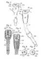
- FIG. 4is a cross-sectional view of the male mating element of the connector taken along lines 4 - 4 of FIG. 3 ;
- FIG. 5is a is a cross-sectional view of the female mating element of the connector taken along lines 5 - 5 of FIG. 3 ;
- FIG. 6is a top view indicative of the male mating surface of FIG. 4 ;
- FIG. 7is a top view indicative of the female mating surface of FIG. 5 .
- FIG. 8is a perspective view of the magnetic connector of the invention illustrating the male and female mating faces for an embodiment providing stereophonic signal capability
- FIG. 9is a cross-sectional view of the male mating element of the magnetic connector of FIG. 8 taken along lines 9 - 9 of FIG. 8 ;
- FIG. 10is a is a cross-sectional view of the female mating element of the connector of FIG. 8 taken along lines 10 - 10 of FIG. 8 ;
- FIG. 11is a top view indicative of the male mating surface of FIG. 9 ;
- FIG. 12is a top view indicative of the female mating surface of FIG. 10 .
- the basic coaxial cableincludes a central signal conductor surrounded by an inner insulation layer, which is encased in a flexible conductive braid tube or sleeve, the assembly then being enclosed in an outer insulating layer.
- the central conductoris ordinarily a multi-stranded or solid conductor.
- FIG. 1is a perspective view illustrating the magnetic connector of the invention, generally designated 10 , as used in connecting, by means of coaxial cable 11 , a musical instrument such as a guitar 12 to a loud speaker 13 .
- Cable 11is connected to speaker 13 in any manner as is conventional with co-axial cables.
- FIG. 2illustrates the break-away characteristic of the invention, connector 10 being inadvertently disconnected by an entangled foot, generally designated 20 .
- Shownis male connector element 10 a connected to guitar 12 by means of a conventional coaxial jack or plug, as will be discussed, and cable 11 having female connector element 10 b at one end for mating with connector element 10 a and at the other end connected to speaker 13 .
- the location of the male element 10 a and female element 10 bcould be reversed such that the female element 10 b is connected to the guitar 12 with he male element 10 a connected to the cable 11 .
- FIG. 3illustrates the male 10 a and female 10 b mating faces of connector 10 .
- Male element 10 aincludes the metallic, signal conductive pin contact 30 , cylindrical insulator member 31 a , permanent magnet 32 a , and tubular conductive metallic shielding/ground sleeve 33 a .
- rubber housing 34 for male element 10 a and conventional jack or plug 35 ais included.
- Female element 12 bincludes the metallic, signal conductive socket 36 for receiving pin contact 30 , cylindrical dielectric insulator member 31 b , permanent magnet 32 b of opposite polarity to permanent magnet 32 a , and conductive shielding/ground sleeve 33 b for abutting connective relationship with shielding/ground 33 a of male element 10 a .
- rubber housing 37 for female element 12 b , cable 11 and conventional jack or plug 35 bis included.
- FIG. 4illustrates male mating element 10 a taken along lines 4 - 4 of FIG. 3 .
- the signal pin 30is responsive to spring means 30 a providing that pin 30 protrudes sufficiently to mate with signal socket 36 thereby to establish and maintain signal integrity through connector 10 .
- Pin contact 30is connected to flexible signal strip 30 b that extends through spring means 30 a and connects to the signal conductor of cable 11 to maintain signal contact with the signal conductor of plug 35 a .
- Pin 30is generally T-shaped having a generally circular base for abutment with the top of spring means 30 a .
- Spring means 30 arests on shoulders provided by cylindrical dielectric member 31 a .
- spring means 30 aurges pin 30 to protrude from the mating surface of male element 10 a .
- Pin 30 , spring means 30 a and signal strip 30 bare enclosed by elongated cylindrical dielectric member 31 a and in turn surrounded by elongated cylindrical magnet 32 a , which in turn is surrounded by shielding/ground 33 a .
- Shielding/ground 33 ais configured in a circular manner to sufficiently cover the mating surface of male element 10 a such that when abuttingly mated with the corresponding shielding/ground 33 b ( FIG. 5 ) of female element 10 b appropriate signal shielding is achieved.
- the dielectric member 31 a and housing/ground 33 ahave openings configured with inner diameters permitting protrusion of pin contact 30 therethrough. Shielding/ground 33 a is shown connected by ground strip 33 c to the ground of coaxial plug 35 a . Although shown in a conventional manner, spring means 30 a may take any configuration as appropriate.
- FIG. 5illustrates female mating element 10 b of connector 10 taken along lines 5 - 5 of FIG. 3 .
- Signal socket 36is recessed for receiving pin contact 30 for mating of elements 10 a and 10 b .
- Socket 36is surrounded by dielectric insulator 31 b , and in turn by cylindrical permanent magnet 32 b which is of opposite polarity to magnet 32 a , and in turn surrounded by shielding/ground sleeve 33 b which is configured for mating with shielding/ground 33 a of male element 10 a .
- the open end of receiving socket 36is generally coplanar with adjacent insulation 31 b and magnet 32 b .
- Shielding/ground 33 bis shown connected by ground strip 33 d to the ground of cable 11 .
- rubber housing 37is also shown.
- the force of spring means 30 ainitially has pin 30 protruding from the shielding/ground 33 a mating surface.
- the force of the magnets 32 a and 32 bwill “grab” the elements and pull them together with any mismatch of pin 30 and socket 36 depressing pin 30 to compress spring means 30 a whereby pin 30 no longer protrudes from shielding/ground 33 a .
- pin 30will be forced into socket 36 by spring means 30 a .
- the attraction force of magnets 32 a , 32 bis such as to maintain connection of the mating elements 10 a , 10 b under normal conditions while disconnecting when subjected to inadvertent disconnect forces.
- Shielding/grounds 33 a and 33 bare configured in a circular manner to sufficiently cover the mating surfaces of elements 10 a and 10 b respectively and are in full abutment when pin 30 is connected to receiving socket 36 by means of magnets 32 a and 32 b , thus providing a continuous electrical shield protecting the signal on the center conductor of cable 11 by minimizing stray interference.
- Insulators 31 a and 31 b , and other connector components,have proper spacing and dielectric constants to ensure that electrical impedance is sufficiently matched, thereby minimizing electrical losses due to reflections or leakage.
- FIG. 6is a top view further indicating the configuration of the male connector element 10 a . Shown as previously described is pin 30 , insulator 3 l a , magnet 32 a , shield/ground 33 a and housing 34 .
- FIG. 7is a top plan view further indicating the configuration of the mating surface of female connector element 10 b . Shown as previously described is socket 36 , insulator 31 a , magnet 32 b , shield/ground 33 b and housing 37 .
- FIG. 8illustrates another embodiment of the magnetic connector of the invention for providing stereophonic signal capability.
- the male elementincludes first and second signal conductive pins 80 a and 80 b respectively, dielectric insulator member 81 encompassing both signal pins 80 a and 80 b and insulating one from the other, permanent magnet 82 , tubular conductive metallic shielding/ground sleeve 83 , rubber housing 84 , and jack 85 .
- the female elementincludes first signal socket 91 a for receiving pin 80 a insulated by first dielectric member 92 a , second signal socket 91 b for receiving pin 80 b insulated by dielectric member 92 b , magnet 93 of opposite polarity to magnet 82 surrounded by shielding/ground 94 which is configured for mating with shielding/ground 83 of the male element, and housing 95 . Also shown is cable 96 and plug 97 .
- FIG. 9illustrates in cross-section the male mating surface of the connector of FIG. 8 taken along lines 9 - 9 thereof. Shown are first and second signal pins 80 a and 80 b , insulator member 81 , permanent magnet 82 , conductive shielding/ground sleeve 83 , housing 84 , and jack 85 .
- Signal pins 80 a and 80 binclude spring means 80 c and 80 d , respectively, and flexible signal strips as previously described.
- Shielding/ground 83is connected to ground strip 86 which is wound around the signal leads and connected to the ground of jack 85 .
- this stereophonic signal embodimentincludes addition of a second signal configuration having pin 80 b that is substantially identical to, but insulated from, the first signal configuration having pin 80 a , the configurations having a common ground.
- Spring means 80 c , 80 d and associated signal stripsmay be of any suitable configuration in accordance with the invention.
- FIG. 10illustrates in cross-section the female mating surface of the connector of FIG. 8 taken along lines 10 - 10 thereof.
- Signal conductive sockets 91 a and 91 bare recessed for receiving pin contacts 80 a and 80 b respectively upon connection of the male and female elements.
- Socket 91 ais centrally placed surrounded by dielectric insulator 92 a , and in turn by circular formed socket 91 b which is then insulated by dielectric 92 b , which is then surrounded by cylindrical magnet 93 of opposite polarity to magnet 82 , and in turn by surrounded by shielding/ground sleeve 94 for mating with shielding/ground 83 of the male element.
- Shielding/ground 94is shown connected by ground lead 98 to the ground of cable 97 .
- rubber housing 95is also shown.
- FIG. 11is a top view further indicating the configuration of the male mating surface of FIG. 9 . Shown as previously described is first and second signal pins 80 a and 80 b , insulator member 81 , permanent magnet 82 , conductive shielding/ground sleeve 83 , and rubber housing 84 .
- FIG. 12is a top view further indicating the configuration of the female mating surface of FIG. 10 . Shown as previously described is signal conductive sockets 91 a and 91 b , dielectric insulators 92 a and 92 b , magnet 93 , shielding/ground sleeve 94 , and rubber housing 95 .
- the procedureis similar to that of the single signal configuration as previously explained. That is, the force of the spring means in each case initially has the contact pins protruding from the shielding/ground mating surface but when bringing the mating elements close proximity the magnets pull the mating elements together with mismatch depressing the pins against the spring means whereby the pins no longer protrude. Once the mismatch is corrected the pins will be forced into the sockets by expansion of the compressed spring means.
Landscapes
- Details Of Connecting Devices For Male And Female Coupling (AREA)
- Details Of Audible-Bandwidth Transducers (AREA)
- Coupling Device And Connection With Printed Circuit (AREA)
Abstract
Description
The background of the invention will be discussed in two parts.
1. Field of the Invention
The invention relates to electrical coaxial cables, and more particularly, to magnetic hold and release connector apparatus for a coaxial cable.
2. Description of the Prior Art
A great variation of electrical connectors is to be found in the marketplace, each generally optimized for a particular usage with a particular set of electrical characteristics. Design of an electrical connector for a particular usage will include the electrical parameters for the circuit in which the connector will be used, the sensitivity of the connector to the environment in which it will be used, the ease in which the connection/disconnection can be made, the desired reliability of the connection, and the expected cost of the connector,.
In considering the ease in which the connection/disconnection can be made, connectors having magnetic hold and release capabilities have been developed. One cable connector arrangement exemplary of the prior art is shown and described in U.S. Pat. No. 4,025,964, issued to Owens on 31 May 1977 wherein the plug is held in the socket by a magnet in the socket and magnetic material in the plug. Another such arrangement is shown and described in U.S. Pat. No. 4,211,456, issued to Sears on 08 Jul. 1980 wherein a male and female electrical connector are held together via a permanent magnet inside the female connector.
Such devices are illustrative of arrangements whereby attempts have been made to provide magnetic disconnects for electrical connectors. However, there is a need for a magnetic disconnect for coaxial connectors providing ease of connection/disconnection combined with desired reliability of the connection. For a coaxial cable system, the objective of the connector is to provide a coacting male and female arrangement with magnetic connective capability wherein the impedance of the system in use is not materially affected. Coaxial cables generally include a center conductor surrounded by an insulation layer which in turn is surrounded by a flexible braid tube or sleeve. In the connector both male and female portions include a central contact electrically connected to the center conductor and some form of sleeve construction connected to the braid and surrounding the interconnected male and female central contacts. An embodiment is included for a dual feed as may be used in a stereophonic system.
It is thus an aspect of the present invention to provide a new and improved configuration for a coaxial cable that is easily attached and detached whereby the force holding the male and female connector elements together is by a permanent magnet. It is a further objective of the invention to provide a coaxial cable that is suitable for use in an environment in which it is subject to frequent inadvertent disconnection during its useful life. It is another aspect of the invention to provide magnetic connector means for a coaxial cable that easily and reliably releases when subjected to pull away forces with the result that the cable is not thereby damaged.
In accordance with the present invention, there is disclosed a co-axial cable connector wherein the connective means between the male and female elements includes permanent magnets, a magnet element of one polarity in the male element and one of opposite polarity in the female element. The male and female elements are configured to allow a reliable electrical connection to be created via the magnetic attraction of the two elements while at the same time allowing for quick and easy disconnect without damage when the connector is subjected to inadvertent pull away forces. With mating of the male and female elements a continuous electrical shield is provided protecting the signal on the center conductor of the coaxial cable by minimizing stray interference. Insulators and other connector components, have proper spacing and dielectric constants to ensure that electrical impedance is sufficiently matched, thereby minimizing electrical losses due to reflections or leakage. When connecting a musical instrument to a speaker and subjecting the connector to quick inadvertent disconnect there is no resultant disruptive noise nor is there damage to the electrical system.
Referring now to the drawings, in which like reference numerals refer to like elements in the several views, there is illustrated a first embodiment of the magnetic connector of the invention wherein mated male and female elements of a co-axial contact system include a permanent magnet for the connective force between the male and female elements. The male and female elements are designed and configured to provide a reliable electrical connection via the magnetic attraction of the two elements while at the same time allowing for quick and easy disconnect of the elements without damage to the connector when subjected to inadvertent pull away forces. As is conventional, the basic coaxial cable includes a central signal conductor surrounded by an inner insulation layer, which is encased in a flexible conductive braid tube or sleeve, the assembly then being enclosed in an outer insulating layer. The central conductor is ordinarily a multi-stranded or solid conductor. When connecting a musical instrument to a speaker and subjecting the connector to abrupt disconnect there is no resultant disruptive noise nor is there damage to the electrical system.
In connection ofmale element 10aandfemale element 10bthe force of spring means30ainitially haspin 30 protruding from the shielding/ground 33amating surface. When bringing themating elements magnets pin 30 andsocket 36depressing pin 30 to compress spring means30awherebypin 30 no longer protrudes from shielding/ground 33a. Once the mismatch is correctedpin 30 will be forced intosocket 36 by spring means30a. The attraction force ofmagnets mating elements
Shielding/grounds elements pin 30 is connected to receivingsocket 36 by means ofmagnets cable 11 by minimizing stray interference.Insulators
In connection of male and female elements of the stereophonic embodiment the procedure is similar to that of the single signal configuration as previously explained. That is, the force of the spring means in each case initially has the contact pins protruding from the shielding/ground mating surface but when bringing the mating elements close proximity the magnets pull the mating elements together with mismatch depressing the pins against the spring means whereby the pins no longer protrude. Once the mismatch is corrected the pins will be forced into the sockets by expansion of the compressed spring means.
The invention has been shown and described with reference to specific illustrated embodiments. It is realized that those skilled in the art may make changes or modifications in the invention without departing from the true scope and spirit of it. Therefore, the scope and spirit of the invention should not be limited to the embodiments discussed, but only by the invention as claimed.
Claims (18)
1. A connector assembly for a coaxial cable comprising:
a first element having a conductive signal member and a second element having a complementary member for contacting said signal member;
said first element and said second element having mating faces for electrically mating said signal member and said complementary member;
magnetic means in said first and second elements for maintaining connection of said elements while disconnecting said elements upon subjection of disconnect forces to said cable; and
said mating faces are electrically connected to respective cable braids and extend beyond respective magnetic means of said first and second elements.
2. The connector assembly ofclaim 1 wherein said connector further includes spring means for urging contact of said signal member and said complementary member.
3. The connector assembly ofclaim 1 wherein mating of said mating faces provides a continuous electrical shield with matched electrical impedance between said male element and said female element thereby to provide an electrical circuit connection preventing acoustic noise or electrical circuit damage when subjected to abrupt disconnection.
4. The connector assembly ofclaim 2 wherein said signal member is connected to the central conductor of said coaxial cable by flexible signal conductive means for maintaining signal continuity independent of the compression state of said spring means.
5. The connector assembly ofclaim 4 wherein said first element includes a plurality of signal members and said second element includes complementary contact members.
6. A coaxial cable connector assembly for connecting a first cable to a second cable, each cable having a central conductor covered by an inner insulation layer with a conductive braid in turn covering said inner insulating layer, said assembly comprising:
a first conductive element including a signal member having a pin contact part and a pin attachment part conductively connected to a flexible conductor in turn connected to the central conductor of said first cable, a first dielectric member encircling said pin attachment part and said flexible conductor and extending over a portion of said pin contact part, a first magnet member encircling said first dielectric member, and a first conductive shielding means encircling said first magnet member and extending over said first magnet member to provide a generally planar mating face for said first element, said first shielding means electrically connected to the braid of said first cable;
a second conductive element including a first end for conductively connecting to the central conductor of said second cable and a second end for complementary contact with said pin contact part, a second dielectric member encircling said second end; a second magnet member encircling said second dielectric member, and a second conductive shielding means extending over said second magnet member to provide a generally planar face for mating with said mating face of said first element, said second shielding means electrically connected to said braid; and
wherein said first and second magnet members are of opposite polarity providing that said first and second elements when mated at their respective mating faces remain continuously connected in the absence of excessive break away forces.
7. The connector assembly ofclaim 6 wherein said pin attachment part includes spring means compressing in response to pressure applied to said pin contact part to allow depression of said pin contact part into said first element, and expanding at released pressure to establish contact with said second end of said second element.
8. The connector assembly ofclaim 6 wherein the mating of said first and second elements provide a continuous electrical shield with matched electrical impedance between said first and said second cables.
9. The connector assembly ofclaim 6 wherein the mating of said first and second elements in an acoustic system provides an electrical circuit connection preventing acoustic noise or electrical circuit damage when subjected to abrupt disconnection.
10. The connector assembly ofclaim 7 wherein said first element includes a plurality of pin members and said second element includes complementary contact members.
11. A connector assembly for a coaxial cable comprising:
first and second mating elements, said first element having a signal conductive member for mating with a complementary member in said second element;
said first and second elements having mating surfaces with respective magnetic means for maintaining connection of said first and second elements and disconnecting said first and second elements upon subjection of disruptive forces to said connector assembly; and
said first and second elements including respective conductive shielding means connected to respective grounded braids and extending over respective magnetic means.
12. The connector assembly ofclaim 11 wherein said magnetic means includes a permanent magnet in said first element and a permanent magnet of opposite polarity in said second element.
13. The connector assembly ofclaim 11 wherein the mating of said first and second elements provides a continuous electrical shield.
14. The connector assembly ofclaim 11 whereby the mating of said first and second elements provide matched electrical impedance between said first and second elements to thereby provide an electrical circuit connection preventing acoustic noise or electrical circuit damage when said first and second elements are subjected to abrupt disconnection.
15. The connector assembly ofclaim 11 including spring means for urging electrical connection of said first and second elements and wherein said connector includes flexible signal conductive means for maintaining signal continuity independent of the compression state of said spring means.
16. The connector assembly ofclaim 11 wherein said signal member includes a pin contact part and a pin attachment part conductively connected to a flexible conductor in turn connected to the central conductor of a first coaxial cable, a first dielectric member encircling said pin attachment part and said flexible conductor and extending over a portion of said pin contact part, a first magnet member encircling said first dielectric member, and a first conductive shielding means encircling said first magnet member and extending over said first magnet member to provide a generally planar mating face for said first element, said first shielding means electrically connected to the braid of said first cable; and
said second element includes a first end for conductively connecting to the central conductor of a second coaxial cable and a second end connected to said complementary member for conductively connecting to said pin contact part, a second dielectric member encircling said second end; a second magnet member encircling said second dielectric member, and a second conductive shielding means extending over said second magnet member to provide a generally planar face for mating with said mating face of said first element, said second shielding means electrically connected to the braid of said second cable.
17. The connector assembly ofclaim 16 wherein said first element includes a plurality of pin members and said second element includes complementary contact members.
18. The connector assembly ofclaim 16 wherein the mating of said first and second elements in an acoustic system provides an electrical circuit connection preventing acoustic noise or electrical circuit damage when subjected to abrupt disconnection.
Priority Applications (7)
| Application Number | Priority Date | Filing Date | Title |
|---|---|---|---|
| US11/445,271US7264479B1 (en) | 2006-06-02 | 2006-06-02 | Coaxial cable magnetic connector |
| PCT/US2006/030853WO2007142661A2 (en) | 2006-06-02 | 2006-08-08 | Coaxial cable magnetic connector |
| DE112006003908TDE112006003908T5 (en) | 2006-06-02 | 2006-08-08 | Magnetic coaxial cable connector |
| JP2009513123AJP2009539224A (en) | 2006-06-02 | 2006-08-08 | Magnetic connector for coaxial cable |
| GB0807087AGB2444693B (en) | 2006-06-02 | 2006-08-08 | Coaxial cable magnetic connector |
| CNU2006201321710UCN200997477Y (en) | 2006-06-02 | 2006-08-11 | Coaxial cable magnetic connecter |
| KR1020070048083AKR20070115619A (en) | 2006-06-02 | 2007-05-17 | Magnetic Connector for Coaxial Cable |
Applications Claiming Priority (1)
| Application Number | Priority Date | Filing Date | Title |
|---|---|---|---|
| US11/445,271US7264479B1 (en) | 2006-06-02 | 2006-06-02 | Coaxial cable magnetic connector |
Publications (1)
| Publication Number | Publication Date |
|---|---|
| US7264479B1true US7264479B1 (en) | 2007-09-04 |
Family
ID=38456833
Family Applications (1)
| Application Number | Title | Priority Date | Filing Date |
|---|---|---|---|
| US11/445,271Expired - Fee RelatedUS7264479B1 (en) | 2006-06-02 | 2006-06-02 | Coaxial cable magnetic connector |
Country Status (7)
| Country | Link |
|---|---|
| US (1) | US7264479B1 (en) |
| JP (1) | JP2009539224A (en) |
| KR (1) | KR20070115619A (en) |
| CN (1) | CN200997477Y (en) |
| DE (1) | DE112006003908T5 (en) |
| GB (1) | GB2444693B (en) |
| WO (1) | WO2007142661A2 (en) |
Cited By (96)
| Publication number | Priority date | Publication date | Assignee | Title |
|---|---|---|---|---|
| US20070254510A1 (en)* | 2006-04-27 | 2007-11-01 | Debey Henry C | Magnetically Retained Electrical Connector |
| US20080067044A1 (en)* | 2006-09-20 | 2008-03-20 | United Technologies Corporation | Electrical interconnection having magnetic conductive elements |
| US20080266762A1 (en)* | 2007-04-25 | 2008-10-30 | Cyber Power System Inc. | Electronic device casing with a plug housing |
| DE202008013600U1 (en) | 2008-08-12 | 2008-12-24 | Magcode Ag | Device for producing a compound |
| US20090176383A1 (en)* | 2008-01-07 | 2009-07-09 | Einam Yitzhak Amotz | Apparatus and method for transferring power from a stationary unit to a mobile unit |
| US20090242539A1 (en)* | 2008-04-01 | 2009-10-01 | Wassel Damian A | Heating System |
| US7607920B1 (en)* | 2008-06-19 | 2009-10-27 | Hon Hai Precision Industry Co., Ltd. | Connecting device for interconnecting electronic devices |
| US20090317985A1 (en)* | 2008-06-23 | 2009-12-24 | Raytheon Company | Magnetic Interconnection Device |
| US20100285674A1 (en)* | 2008-01-07 | 2010-11-11 | Arnon Haim David | Apparatus for transferring electrical power |
| US20110086519A1 (en)* | 2009-10-08 | 2011-04-14 | Jts Professional Co., Ltd. | Wireless transmitter with securely adjustable pivotal plug for connecting to musical instrument |
| US20110084474A1 (en)* | 2008-06-25 | 2011-04-14 | Paden David B | High retention magnetic coupling device for conduit attachment |
| US20110171837A1 (en)* | 2010-01-11 | 2011-07-14 | AUTOMOTIVE INDUSTRIAL MARKETING CORP., dba AIMCO | Magnetic cable connector systems |
| US8016599B1 (en) | 2010-03-30 | 2011-09-13 | Steve Melby | Magnetic jumper for bypassing electrical circuits |
| US20110260686A1 (en)* | 2010-04-23 | 2011-10-27 | Ford Timothy D F | Universal battery pack and powering system |
| EP2469662A1 (en)* | 2010-12-22 | 2012-06-27 | Research In Motion Limited | Self-Orienting Electrical Connector |
| US8272876B2 (en) | 2010-07-20 | 2012-09-25 | Magnetic Innovations, L.L.C. | Magnetically enhanced electrical signal conduction apparatus and methods |
| US20120244732A1 (en)* | 2011-03-24 | 2012-09-27 | Correlated Magnetics Research, Llc. | Electrical adapter system |
| WO2013003781A1 (en)* | 2011-06-30 | 2013-01-03 | Apple Inc. | Robust magnetic connector |
| US8382486B2 (en) | 2010-12-22 | 2013-02-26 | Research In Motion Limited | Self-orienting electrical connector |
| ITPI20110130A1 (en)* | 2011-11-21 | 2013-05-22 | Microtech S R L | CONNECTOR STRUCTURE FOR A MEDICAL LINE |
| US20130210244A1 (en)* | 2011-08-11 | 2013-08-15 | Apple Inc. | Magnetic arrangements and labels for connectors |
| WO2013184906A1 (en)* | 2012-06-08 | 2013-12-12 | Apple Inc. | Connector adapter |
| US8638016B2 (en) | 2010-09-17 | 2014-01-28 | Correlated Magnetics Research, Llc | Electromagnetic structure having a core element that extends magnetic coupling around opposing surfaces of a circular magnetic structure |
| US8643454B2 (en) | 2008-04-04 | 2014-02-04 | Correlated Magnetics Research, Llc | Field emission system and method |
| US20140077044A1 (en)* | 2012-05-08 | 2014-03-20 | Otter Products, Llc | Connection mechanism |
| US8692637B2 (en) | 2008-04-04 | 2014-04-08 | Correlated Magnetics Research LLC | Magnetic device using non polarized magnetic attraction elements |
| US8690582B2 (en) | 2005-09-26 | 2014-04-08 | Apple Inc. | Magnetic connector for electronic device |
| US8704626B2 (en) | 2010-05-10 | 2014-04-22 | Correlated Magnetics Research, Llc | System and method for moving an object |
| US8760251B2 (en) | 2010-09-27 | 2014-06-24 | Correlated Magnetics Research, Llc | System and method for producing stacked field emission structures |
| US8760252B2 (en) | 2008-04-04 | 2014-06-24 | Correlated Magnetics Research, Llc | Field emission system and method |
| US8760250B2 (en) | 2009-06-02 | 2014-06-24 | Correlated Magnetics Rsearch, LLC. | System and method for energy generation |
| US8779879B2 (en) | 2008-04-04 | 2014-07-15 | Correlated Magnetics Research LLC | System and method for positioning a multi-pole magnetic structure |
| US20140220793A1 (en)* | 2013-02-04 | 2014-08-07 | Kingston Digital, Inc. | Connecting device and electronic device assembly |
| US8816805B2 (en) | 2008-04-04 | 2014-08-26 | Correlated Magnetics Research, Llc. | Magnetic structure production |
| US8841981B2 (en) | 2011-03-24 | 2014-09-23 | Correlated Magnetics Research, Llc. | Detachable cover system |
| US8848973B2 (en) | 2011-09-22 | 2014-09-30 | Correlated Magnetics Research LLC | System and method for authenticating an optical pattern |
| US8917154B2 (en) | 2012-12-10 | 2014-12-23 | Correlated Magnetics Research, Llc. | System for concentrating magnetic flux |
| US8937521B2 (en) | 2012-12-10 | 2015-01-20 | Correlated Magnetics Research, Llc. | System for concentrating magnetic flux of a multi-pole magnetic structure |
| US8947185B2 (en) | 2010-07-12 | 2015-02-03 | Correlated Magnetics Research, Llc | Magnetic system |
| US8944826B1 (en) | 2013-07-16 | 2015-02-03 | Curbell Medical Products, Inc. | Magnetic connection for cable assembly of electronic device |
| US8957751B2 (en) | 2010-12-10 | 2015-02-17 | Correlated Magnetics Research LLC | System and method for affecting flux of multi-pole magnetic structures |
| US8963380B2 (en) | 2011-07-11 | 2015-02-24 | Correlated Magnetics Research LLC. | System and method for power generation system |
| US8970332B2 (en) | 2005-09-26 | 2015-03-03 | Apple Inc. | Electromagnetic connector for electronic device |
| US9065205B2 (en) | 2011-08-11 | 2015-06-23 | Apple Inc. | Connector insert having a cable crimp portion with protrusions and a receptacle having label in the front |
| US9083099B2 (en) | 2013-09-13 | 2015-07-14 | Young Chang T.I.W. Co., Ltd. | Magnetic alligator clip |
| US9080734B2 (en) | 2013-05-03 | 2015-07-14 | Cade Andersen | Modular flash light with magnetic connection |
| US9105380B2 (en) | 2008-04-04 | 2015-08-11 | Correlated Magnetics Research, Llc. | Magnetic attachment system |
| US9112303B2 (en) | 2012-06-04 | 2015-08-18 | Adonit Co., Ltd. | Magnetic connector |
| US20150333458A1 (en)* | 2014-05-16 | 2015-11-19 | Magzet, Llc | Releasable plug connector system |
| US9202616B2 (en) | 2009-06-02 | 2015-12-01 | Correlated Magnetics Research, Llc | Intelligent magnetic system |
| US9202615B2 (en) | 2012-02-28 | 2015-12-01 | Correlated Magnetics Research, Llc | System for detaching a magnetic structure from a ferromagnetic material |
| US9219403B2 (en) | 2011-09-06 | 2015-12-22 | Correlated Magnetics Research, Llc | Magnetic shear force transfer device |
| US20160013582A1 (en)* | 2014-07-10 | 2016-01-14 | Norman R. Byrne | Electrical power coupling with magnetic connections |
| US9245677B2 (en) | 2012-08-06 | 2016-01-26 | Correlated Magnetics Research, Llc. | System for concentrating and controlling magnetic flux of a multi-pole magnetic structure |
| US9257219B2 (en) | 2012-08-06 | 2016-02-09 | Correlated Magnetics Research, Llc. | System and method for magnetization |
| US9275783B2 (en) | 2012-10-15 | 2016-03-01 | Correlated Magnetics Research, Llc. | System and method for demagnetization of a magnetic structure region |
| US9298281B2 (en) | 2012-12-27 | 2016-03-29 | Correlated Magnetics Research, Llc. | Magnetic vector sensor positioning and communications system |
| US9300081B2 (en) | 2010-02-02 | 2016-03-29 | Charles Albert Rudisill | Interposer connectors with magnetic components |
| US9330825B2 (en) | 2011-04-12 | 2016-05-03 | Mohammad Sarai | Magnetic configurations |
| US9371923B2 (en) | 2008-04-04 | 2016-06-21 | Correlated Magnetics Research, Llc | Magnetic valve assembly |
| US9385490B2 (en) | 2011-06-02 | 2016-07-05 | Murata Manufacturing Co., Ltd. | Switch-equipped connector |
| US9392823B2 (en) | 2013-07-26 | 2016-07-19 | Lumativ Inc. | Illuminated garment and accessories |
| US9404776B2 (en) | 2009-06-02 | 2016-08-02 | Correlated Magnetics Research, Llc. | System and method for tailoring polarity transitions of magnetic structures |
| US20160226207A1 (en)* | 2011-03-24 | 2016-08-04 | Correlated Magnetics Research, Llc | Electrical adapter system |
| US20160344117A1 (en)* | 2015-05-22 | 2016-11-24 | Korea University Research And Business Foundation | Magnet terminal with solderless connection structure and jumper wire including the same |
| US20170085028A1 (en)* | 2015-09-22 | 2017-03-23 | Simple Socket Inc. | Magnetic electrical connector |
| US9614320B2 (en)* | 2014-08-26 | 2017-04-04 | Google Inc. | Dongle for quick release |
| US9631691B2 (en) | 2013-06-28 | 2017-04-25 | Magnetic Innovations Llc | Vibration dampening devices and methods |
| US9698524B1 (en) | 2012-12-31 | 2017-07-04 | EMC IP Holding Company LLC | Magnetic, self-retracting, auto-aligning electrical connector |
| US9711268B2 (en) | 2009-09-22 | 2017-07-18 | Correlated Magnetics Research, Llc | System and method for tailoring magnetic forces |
| US9733616B2 (en) | 2011-12-28 | 2017-08-15 | Exfo Inc. | Portable digital holographic probe for the inspection of optical fiber connectors, and inspection system and method for the same |
| US20170373420A1 (en)* | 2016-06-23 | 2017-12-28 | Jidai ZHOU | Electrical connector for christmas lamp trees |
| US9912109B2 (en) | 2011-10-28 | 2018-03-06 | Polygroup Macau Limited (Bvi) | Powered tree construction |
| EP3300178A1 (en)* | 2016-09-23 | 2018-03-28 | Apple Inc. | Magnetic rf connectors |
| US9966716B2 (en) | 2015-09-08 | 2018-05-08 | Apple Inc. | Adapter |
| US10177507B2 (en) | 2016-02-12 | 2019-01-08 | Norman R. Byrne | Electrical power load switch with connection sensor |
| US10211578B2 (en)* | 2017-01-18 | 2019-02-19 | Qi Ma | Audio output jack |
| EP3471213A1 (en)* | 2017-10-10 | 2019-04-17 | Shenzhen Prime Logic Technology Co., Ltd. | Apparatus and methods for vehicle battery charging or voltage monitoring |
| US10317015B2 (en)* | 2015-08-19 | 2019-06-11 | Auroralight, Inc. | Light module with self-aligning electrical and mechanical connection |
| US10440795B2 (en) | 2016-03-04 | 2019-10-08 | Polygroup Macau Limited (Bvi) | Variable multi-color LED light string and controller for an artificial tree |
| US10541557B2 (en) | 2016-10-07 | 2020-01-21 | Norman R. Byrne | Electrical power cord with intelligent switching |
| US10548380B2 (en) | 2013-02-01 | 2020-02-04 | Treefrog Developments, Inc. | Waterproof housing for an electronic device |
| US10680383B2 (en) | 2013-03-14 | 2020-06-09 | Apex Technologies, Inc. | Linear electrode systems for module attachment with non-uniform axial spacing |
| USD889416S1 (en)* | 2019-05-29 | 2020-07-07 | Jing Zhao | Data line |
| US10765245B2 (en) | 2009-07-14 | 2020-09-08 | Belgravia Wood Limited | Power pole for artificial tree apparatus with axial electrical connectors |
| US10819075B1 (en)* | 2018-07-19 | 2020-10-27 | Frank Dale Boxberger | Magnetic connector for transmitting power, sound, video and other signals |
| US10842306B2 (en) | 2015-03-27 | 2020-11-24 | Polygroup Macau Limited (Bvi) | Multi-wire quick assemble tree |
| US10973355B2 (en) | 2009-07-14 | 2021-04-13 | Belgravia Wood Limited | Power pole for artificial tree apparatus with axial electrical connectors |
| US10993572B2 (en) | 2009-07-14 | 2021-05-04 | Belgravia Wood Limited | Power pole for artificial tree apparatus with axial electrical connectors |
| US11121502B2 (en)* | 2016-09-23 | 2021-09-14 | Apple Inc. | Magnetic connectors |
| US11266198B2 (en)* | 2016-01-28 | 2022-03-08 | Bombardier Recreational Products Inc. | Connector assembly for a helmet |
| EP4012849A1 (en)* | 2020-12-09 | 2022-06-15 | Pragma GmbH Zittau | Button set for light paging systems |
| US11382380B2 (en) | 2018-02-19 | 2022-07-12 | Bombardier Recreational Products Inc. | Helmet |
| US11424573B2 (en) | 2020-09-24 | 2022-08-23 | Apple Inc. | Magnetic connectors with self-centering floating contacts |
| US11424561B2 (en) | 2019-07-03 | 2022-08-23 | Norman R. Byrne | Outlet-level electrical energy management system |
| US12369670B2 (en) | 2022-02-17 | 2025-07-29 | Kimpex Inc. | Connector for electrical visor and a visor assembly and a helmet having the same |
Families Citing this family (12)
| Publication number | Priority date | Publication date | Assignee | Title |
|---|---|---|---|---|
| CN102148432B (en)* | 2010-02-08 | 2014-07-30 | 富士康(昆山)电脑接插件有限公司 | Cable connector component |
| FR2961026B1 (en)* | 2010-06-07 | 2015-04-17 | Multi Holding Ag | ELECTRICAL CONNECTION ELEMENT, VEHICLE AND RECHARGEING STATION COMPRISING SUCH A MALE ELEMENT, AND ELECTRICAL CONNECTION ASSEMBLY |
| CN102157870B (en)* | 2010-12-31 | 2014-04-30 | 上海航天科工电器研究院有限公司 | Magnetic radio frequency (RF) coaxial connector |
| KR20160024299A (en) | 2014-08-25 | 2016-03-04 | 현대자동차주식회사 | Connetor locked by magnetic force |
| JP2016100106A (en)* | 2014-11-19 | 2016-05-30 | スタッフ株式会社 | Magnet type connector for dc power supply unit |
| DE102015206409A1 (en)* | 2015-04-10 | 2016-10-13 | Hipo Systems Gmbh | Kugelstrecker with recording |
| CN111224254B (en) | 2018-11-27 | 2022-04-05 | 上海莫仕连接器有限公司 | First connector, second connector and electric connector assembly |
| CN114665341A (en)* | 2020-12-22 | 2022-06-24 | 康普技术有限责任公司 | Coaxial connector and assembly thereof |
| KR102677934B1 (en)* | 2021-10-13 | 2024-06-24 | 주식회사 노바텍 | Rf connector |
| KR102592297B1 (en)* | 2021-10-13 | 2023-10-20 | 주식회사 노바텍 | Rf connector including the shieding structure |
| KR102634968B1 (en)* | 2021-10-26 | 2024-02-07 | 주식회사 경신 | Terminal for vehicle |
| KR102634967B1 (en)* | 2021-10-26 | 2024-02-07 | 주식회사 경신 | Terminal for vehicle |
Citations (5)
| Publication number | Priority date | Publication date | Assignee | Title |
|---|---|---|---|---|
| US3521216A (en)* | 1968-06-19 | 1970-07-21 | Manuel Jerair Tolegian | Magnetic plug and socket assembly |
| US3808577A (en)* | 1973-03-05 | 1974-04-30 | W Mathauser | Magnetic self-aligning quick-disconnect for a telephone or other communications equipment |
| US5401175A (en)* | 1993-06-25 | 1995-03-28 | M/A-Com, Inc. | Magnetic coaxial connector |
| US5921783A (en)* | 1995-04-01 | 1999-07-13 | Klaus-Dieter Fritsch | Electromechanical connection device |
| US6565363B2 (en)* | 2001-08-30 | 2003-05-20 | Eric Downing | Magnetic modular jack |
Family Cites Families (5)
| Publication number | Priority date | Publication date | Assignee | Title |
|---|---|---|---|---|
| US4025964A (en) | 1976-07-30 | 1977-05-31 | The United States Of America As Represented By The Administrator Of The National Aeronautics And Space Administration | Magnetic electrical connectors for biomedical percutaneous implants |
| US4211456A (en) | 1979-01-31 | 1980-07-08 | Schick Laboratories, Inc. | Magnetic electrical connectors |
| JPH03179682A (en)* | 1989-12-06 | 1991-08-05 | Mitsubishi Electric Corp | coaxial connector |
| US5401173A (en)* | 1994-02-28 | 1995-03-28 | General Signal Corporation | Coaxial connector accommodating differential expansion |
| JP2004082830A (en)* | 2002-08-26 | 2004-03-18 | Tokai Rika Co Ltd | Junction switch device for door |
- 2006
- 2006-06-02USUS11/445,271patent/US7264479B1/ennot_activeExpired - Fee Related
- 2006-08-08JPJP2009513123Apatent/JP2009539224A/ennot_activeCeased
- 2006-08-08GBGB0807087Apatent/GB2444693B/ennot_activeExpired - Fee Related
- 2006-08-08WOPCT/US2006/030853patent/WO2007142661A2/enactiveApplication Filing
- 2006-08-08DEDE112006003908Tpatent/DE112006003908T5/ennot_activeWithdrawn
- 2006-08-11CNCNU2006201321710Upatent/CN200997477Y/ennot_activeExpired - Fee Related
- 2007
- 2007-05-17KRKR1020070048083Apatent/KR20070115619A/ennot_activeCeased
Patent Citations (5)
| Publication number | Priority date | Publication date | Assignee | Title |
|---|---|---|---|---|
| US3521216A (en)* | 1968-06-19 | 1970-07-21 | Manuel Jerair Tolegian | Magnetic plug and socket assembly |
| US3808577A (en)* | 1973-03-05 | 1974-04-30 | W Mathauser | Magnetic self-aligning quick-disconnect for a telephone or other communications equipment |
| US5401175A (en)* | 1993-06-25 | 1995-03-28 | M/A-Com, Inc. | Magnetic coaxial connector |
| US5921783A (en)* | 1995-04-01 | 1999-07-13 | Klaus-Dieter Fritsch | Electromechanical connection device |
| US6565363B2 (en)* | 2001-08-30 | 2003-05-20 | Eric Downing | Magnetic modular jack |
Cited By (171)
| Publication number | Priority date | Publication date | Assignee | Title |
|---|---|---|---|---|
| US9112304B2 (en) | 2005-09-26 | 2015-08-18 | Apple Inc. | Magnetic connector for electronic device |
| US8970332B2 (en) | 2005-09-26 | 2015-03-03 | Apple Inc. | Electromagnetic connector for electronic device |
| US10090618B2 (en) | 2005-09-26 | 2018-10-02 | Apple Inc. | Magnetic connector for electronic device |
| US9634428B2 (en) | 2005-09-26 | 2017-04-25 | Apple Inc. | Electromagnetic connector for electronic device |
| US10490933B2 (en) | 2005-09-26 | 2019-11-26 | Apple Inc. | Magnetic connector for electronic device |
| US9711893B2 (en) | 2005-09-26 | 2017-07-18 | Apple Inc. | Magnetic connector for electronic device |
| US8690582B2 (en) | 2005-09-26 | 2014-04-08 | Apple Inc. | Magnetic connector for electronic device |
| US11233356B2 (en) | 2005-09-26 | 2022-01-25 | Apple Inc. | Magnetic connector for electronic device |
| US20070254510A1 (en)* | 2006-04-27 | 2007-11-01 | Debey Henry C | Magnetically Retained Electrical Connector |
| US7402045B2 (en)* | 2006-09-20 | 2008-07-22 | United Technologies Corporation | Electrical interconnection having magnetic conductive elements |
| US20080067044A1 (en)* | 2006-09-20 | 2008-03-20 | United Technologies Corporation | Electrical interconnection having magnetic conductive elements |
| US20080266762A1 (en)* | 2007-04-25 | 2008-10-30 | Cyber Power System Inc. | Electronic device casing with a plug housing |
| US20090176383A1 (en)* | 2008-01-07 | 2009-07-09 | Einam Yitzhak Amotz | Apparatus and method for transferring power from a stationary unit to a mobile unit |
| US7771202B2 (en) | 2008-01-07 | 2010-08-10 | Einam Yitzhak Amotz | Apparatus for transferring alternating current electrical power |
| US20100285674A1 (en)* | 2008-01-07 | 2010-11-11 | Arnon Haim David | Apparatus for transferring electrical power |
| US7931472B2 (en) | 2008-01-07 | 2011-04-26 | Arnon Haim David | Apparatus for transferring electric power from a mobile unit placed in various orientation on a stationary unit |
| US20090242539A1 (en)* | 2008-04-01 | 2009-10-01 | Wassel Damian A | Heating System |
| US8844121B2 (en) | 2008-04-04 | 2014-09-30 | Correlated Magnetics Research LLC | System and method for manufacturing a field emission structure |
| US9536650B2 (en) | 2008-04-04 | 2017-01-03 | Correlated Magnetics Research, Llc. | Magnetic structure |
| US8857044B2 (en) | 2008-04-04 | 2014-10-14 | Correlated Magnetics Research LLC | System for manufacturing a field emission structure |
| US9269482B2 (en) | 2008-04-04 | 2016-02-23 | Correlated Magnetics Research, Llc. | Magnetizing apparatus |
| US8643454B2 (en) | 2008-04-04 | 2014-02-04 | Correlated Magnetics Research, Llc | Field emission system and method |
| US8692637B2 (en) | 2008-04-04 | 2014-04-08 | Correlated Magnetics Research LLC | Magnetic device using non polarized magnetic attraction elements |
| US9371923B2 (en) | 2008-04-04 | 2016-06-21 | Correlated Magnetics Research, Llc | Magnetic valve assembly |
| US8872608B2 (en) | 2008-04-04 | 2014-10-28 | Correlated Magnetics Reserach LLC | Magnetic structures and methods for defining magnetic structures using one-dimensional codes |
| US8816805B2 (en) | 2008-04-04 | 2014-08-26 | Correlated Magnetics Research, Llc. | Magnetic structure production |
| US8779879B2 (en) | 2008-04-04 | 2014-07-15 | Correlated Magnetics Research LLC | System and method for positioning a multi-pole magnetic structure |
| US8760252B2 (en) | 2008-04-04 | 2014-06-24 | Correlated Magnetics Research, Llc | Field emission system and method |
| US9105380B2 (en) | 2008-04-04 | 2015-08-11 | Correlated Magnetics Research, Llc. | Magnetic attachment system |
| US9105384B2 (en) | 2008-04-04 | 2015-08-11 | Correlated Megnetics Research, Llc. | Apparatus and method for printing maxels |
| US7607920B1 (en)* | 2008-06-19 | 2009-10-27 | Hon Hai Precision Industry Co., Ltd. | Connecting device for interconnecting electronic devices |
| US20090317985A1 (en)* | 2008-06-23 | 2009-12-24 | Raytheon Company | Magnetic Interconnection Device |
| US8232928B2 (en) | 2008-06-23 | 2012-07-31 | Raytheon Company | Dual-polarized antenna array |
| US8058957B2 (en) | 2008-06-23 | 2011-11-15 | Raytheon Company | Magnetic interconnection device |
| US20090315802A1 (en)* | 2008-06-23 | 2009-12-24 | Raytheon Company | Dual-Polarized Antenna Array |
| US20110084474A1 (en)* | 2008-06-25 | 2011-04-14 | Paden David B | High retention magnetic coupling device for conduit attachment |
| DE202008013600U1 (en) | 2008-08-12 | 2008-12-24 | Magcode Ag | Device for producing a compound |
| DE102008038649A1 (en) | 2008-08-12 | 2010-02-18 | Rosenberger Hochfrequenztechnik Gmbh & Co. Kg | Device for producing a compound |
| WO2010017951A1 (en)* | 2008-08-12 | 2010-02-18 | Rosenberger Hochfrequenztechnik Gmbh & Co. Kg | Method for producing a connection |
| US8398409B2 (en) | 2008-08-12 | 2013-03-19 | Rosenberger Hochfrequenztechnik Gmbh & Co Kg | Apparatus for producing a connection |
| US8760250B2 (en) | 2009-06-02 | 2014-06-24 | Correlated Magnetics Rsearch, LLC. | System and method for energy generation |
| US9367783B2 (en) | 2009-06-02 | 2016-06-14 | Correlated Magnetics Research, Llc | Magnetizing printer and method for re-magnetizing at least a portion of a previously magnetized magnet |
| US9202616B2 (en) | 2009-06-02 | 2015-12-01 | Correlated Magnetics Research, Llc | Intelligent magnetic system |
| US9404776B2 (en) | 2009-06-02 | 2016-08-02 | Correlated Magnetics Research, Llc. | System and method for tailoring polarity transitions of magnetic structures |
| US10973355B2 (en) | 2009-07-14 | 2021-04-13 | Belgravia Wood Limited | Power pole for artificial tree apparatus with axial electrical connectors |
| US11096512B2 (en) | 2009-07-14 | 2021-08-24 | Belgravia Wood Limited | Power pole for artificial tree apparatus with axial electrical connectors |
| US11083319B2 (en) | 2009-07-14 | 2021-08-10 | Belgravia Wood Limited | Power pole for artificial tree apparatus with axial electrical connectors |
| US12226037B2 (en) | 2009-07-14 | 2025-02-18 | Belgravia Wood Limited | Power pole for artificial tree apparatus with axial electrical connectors |
| US11013356B2 (en) | 2009-07-14 | 2021-05-25 | Belgravia Wood Limited | Power pole for artificial tree apparatus with axial electrical connectors |
| US10939777B2 (en) | 2009-07-14 | 2021-03-09 | Belgravia Wood Limited | Power pole for artificial tree apparatus with axial electrical connectors |
| US10993572B2 (en) | 2009-07-14 | 2021-05-04 | Belgravia Wood Limited | Power pole for artificial tree apparatus with axial electrical connectors |
| US10893768B2 (en) | 2009-07-14 | 2021-01-19 | Belgravia Wood Limited | Power pole for artificial tree apparatus with axial electrical connectors |
| US10765244B2 (en) | 2009-07-14 | 2020-09-08 | Belgravia Wood Limited | Power pole for artificial tree apparatus with axial electrical connectors |
| US11712126B2 (en) | 2009-07-14 | 2023-08-01 | Belgravia Wood Limited | Power pole for artificial tree apparatus with axial electrical connectors |
| US11096511B2 (en) | 2009-07-14 | 2021-08-24 | Belgravia Wood Limited | Power pole for artificial tree apparatus with axial electrical connectors |
| US10993571B2 (en) | 2009-07-14 | 2021-05-04 | Belgravia Wood Limited | Architecture for routing multi-channel commands via a tree column |
| US10765245B2 (en) | 2009-07-14 | 2020-09-08 | Belgravia Wood Limited | Power pole for artificial tree apparatus with axial electrical connectors |
| US9711268B2 (en) | 2009-09-22 | 2017-07-18 | Correlated Magnetics Research, Llc | System and method for tailoring magnetic forces |
| US7955084B2 (en)* | 2009-10-08 | 2011-06-07 | Jts Professional Co., Ltd. | Wireless transmitter with securely adjustable pivotal plug for connecting to musical instrument |
| US20110086519A1 (en)* | 2009-10-08 | 2011-04-14 | Jts Professional Co., Ltd. | Wireless transmitter with securely adjustable pivotal plug for connecting to musical instrument |
| US20110171837A1 (en)* | 2010-01-11 | 2011-07-14 | AUTOMOTIVE INDUSTRIAL MARKETING CORP., dba AIMCO | Magnetic cable connector systems |
| US8348678B2 (en) | 2010-01-11 | 2013-01-08 | Automotive Industrial Marketing Corp. | Magnetic cable connector systems |
| US9300081B2 (en) | 2010-02-02 | 2016-03-29 | Charles Albert Rudisill | Interposer connectors with magnetic components |
| WO2011126536A1 (en)* | 2010-03-30 | 2011-10-13 | Steve Melby | Magnetic jumper for bypassing electrical circuits |
| US8016599B1 (en) | 2010-03-30 | 2011-09-13 | Steve Melby | Magnetic jumper for bypassing electrical circuits |
| US20110260686A1 (en)* | 2010-04-23 | 2011-10-27 | Ford Timothy D F | Universal battery pack and powering system |
| US9413181B2 (en)* | 2010-04-23 | 2016-08-09 | The Flewelling Ford Family Trust | Wearable power supply comprising a master cell and a slave cell |
| US9406424B2 (en) | 2010-05-10 | 2016-08-02 | Correlated Magnetics Research, Llc | System and method for moving an object |
| US8704626B2 (en) | 2010-05-10 | 2014-04-22 | Correlated Magnetics Research, Llc | System and method for moving an object |
| US9111673B2 (en) | 2010-05-10 | 2015-08-18 | Correlated Magnetics Research, Llc. | System and method for moving an object |
| US9583871B1 (en) | 2010-05-13 | 2017-02-28 | Apex Technologies, Inc. | Electrical connector system with ferromagnetic actuators |
| US9111672B2 (en) | 2010-07-12 | 2015-08-18 | Correlated Magnetics Research LLC. | Multilevel correlated magnetic system |
| US8947185B2 (en) | 2010-07-12 | 2015-02-03 | Correlated Magnetics Research, Llc | Magnetic system |
| US9992869B2 (en) | 2010-07-20 | 2018-06-05 | Magnetic Innovations Llc | Magnetically enhanced electrical signal conduction apparatus and methods |
| US8403680B2 (en) | 2010-07-20 | 2013-03-26 | Magnetic Innovations Llc | Magnetically enhanced electrical signal conduction apparatus and methods |
| US8272876B2 (en) | 2010-07-20 | 2012-09-25 | Magnetic Innovations, L.L.C. | Magnetically enhanced electrical signal conduction apparatus and methods |
| US10045440B1 (en) | 2010-07-20 | 2018-08-07 | Magnetic Innovations Llc | Magnetically enhanced electrical signal conduction apparatus and methods |
| US9326379B2 (en) | 2010-07-20 | 2016-04-26 | Magnetic Innovations Llc | Magnetically enhanced electrical signal conduction apparatus and methods |
| US8638016B2 (en) | 2010-09-17 | 2014-01-28 | Correlated Magnetics Research, Llc | Electromagnetic structure having a core element that extends magnetic coupling around opposing surfaces of a circular magnetic structure |
| US8760251B2 (en) | 2010-09-27 | 2014-06-24 | Correlated Magnetics Research, Llc | System and method for producing stacked field emission structures |
| US8957751B2 (en) | 2010-12-10 | 2015-02-17 | Correlated Magnetics Research LLC | System and method for affecting flux of multi-pole magnetic structures |
| US8382486B2 (en) | 2010-12-22 | 2013-02-26 | Research In Motion Limited | Self-orienting electrical connector |
| EP2469662A1 (en)* | 2010-12-22 | 2012-06-27 | Research In Motion Limited | Self-Orienting Electrical Connector |
| US10008817B2 (en)* | 2011-03-24 | 2018-06-26 | Correlated Magnetics Research, Llc | Electrical adapter system |
| US8841981B2 (en) | 2011-03-24 | 2014-09-23 | Correlated Magnetics Research, Llc. | Detachable cover system |
| US8702437B2 (en)* | 2011-03-24 | 2014-04-22 | Correlated Magnetics Research, Llc | Electrical adapter system |
| US20140227896A1 (en)* | 2011-03-24 | 2014-08-14 | Correlated Magnetics Research, Llc. | Electrical adapter system |
| US9312634B2 (en)* | 2011-03-24 | 2016-04-12 | Correlated Magnetics Research LLC | Electrical adapter system |
| US20160226207A1 (en)* | 2011-03-24 | 2016-08-04 | Correlated Magnetics Research, Llc | Electrical adapter system |
| US20120244732A1 (en)* | 2011-03-24 | 2012-09-27 | Correlated Magnetics Research, Llc. | Electrical adapter system |
| US9330825B2 (en) | 2011-04-12 | 2016-05-03 | Mohammad Sarai | Magnetic configurations |
| US9385490B2 (en) | 2011-06-02 | 2016-07-05 | Murata Manufacturing Co., Ltd. | Switch-equipped connector |
| US8888500B2 (en)* | 2011-06-30 | 2014-11-18 | Apple Inc. | Robust magnetic connector |
| US9923290B2 (en) | 2011-06-30 | 2018-03-20 | Apple Inc. | Robust magnetic connector |
| US20130005159A1 (en)* | 2011-06-30 | 2013-01-03 | Apple Inc. | Robust magnetic connector |
| WO2013003781A1 (en)* | 2011-06-30 | 2013-01-03 | Apple Inc. | Robust magnetic connector |
| US9461403B2 (en)* | 2011-06-30 | 2016-10-04 | Apple Inc. | Robust magnetic connector |
| US8963380B2 (en) | 2011-07-11 | 2015-02-24 | Correlated Magnetics Research LLC. | System and method for power generation system |
| US9065205B2 (en) | 2011-08-11 | 2015-06-23 | Apple Inc. | Connector insert having a cable crimp portion with protrusions and a receptacle having label in the front |
| US9780484B2 (en)* | 2011-08-11 | 2017-10-03 | Apple Inc. | Magnetic arrangements and labels for connectors |
| US20130210244A1 (en)* | 2011-08-11 | 2013-08-15 | Apple Inc. | Magnetic arrangements and labels for connectors |
| US9660376B2 (en) | 2011-08-11 | 2017-05-23 | Apple Inc. | Connector insert having a cable crimp portion with protrusions and a receptacle having a label in the front |
| US9219403B2 (en) | 2011-09-06 | 2015-12-22 | Correlated Magnetics Research, Llc | Magnetic shear force transfer device |
| US8848973B2 (en) | 2011-09-22 | 2014-09-30 | Correlated Magnetics Research LLC | System and method for authenticating an optical pattern |
| US11967790B2 (en)* | 2011-10-28 | 2024-04-23 | Polygroup Macau Limited (Bvi) | Powered tree construction with rotation limiting |
| US10985513B2 (en) | 2011-10-28 | 2021-04-20 | Polygroup Macau Limited (Bvi) | Powered tree construction with rotation limiting |
| US10777949B2 (en) | 2011-10-28 | 2020-09-15 | Polygroup Macau Limited (Bvi) | Powered tree construction |
| US9912109B2 (en) | 2011-10-28 | 2018-03-06 | Polygroup Macau Limited (Bvi) | Powered tree construction |
| US10522954B1 (en) | 2011-10-28 | 2019-12-31 | Polygroup Macau Limited (Bvi) | Powered tree construction |
| US11799251B2 (en) | 2011-10-28 | 2023-10-24 | Polygroup Macau Limited (Bvi) | Powered tree construction with rotation limiting |
| US10404019B2 (en) | 2011-10-28 | 2019-09-03 | Polygroup Macau Limited (Bvi) | Powered tree construction |
| ITPI20110130A1 (en)* | 2011-11-21 | 2013-05-22 | Microtech S R L | CONNECTOR STRUCTURE FOR A MEDICAL LINE |
| WO2013076667A1 (en)* | 2011-11-21 | 2013-05-30 | Ekymed S.P.A. | Structure of connector for medical lines |
| US9733616B2 (en) | 2011-12-28 | 2017-08-15 | Exfo Inc. | Portable digital holographic probe for the inspection of optical fiber connectors, and inspection system and method for the same |
| US9202615B2 (en) | 2012-02-28 | 2015-12-01 | Correlated Magnetics Research, Llc | System for detaching a magnetic structure from a ferromagnetic material |
| US20140077044A1 (en)* | 2012-05-08 | 2014-03-20 | Otter Products, Llc | Connection mechanism |
| US9437969B2 (en) | 2012-05-08 | 2016-09-06 | Otter Products, Llc | Connection mechanism |
| US9062695B2 (en)* | 2012-05-08 | 2015-06-23 | Otter Products, Llc | Connection mechanism |
| US9112303B2 (en) | 2012-06-04 | 2015-08-18 | Adonit Co., Ltd. | Magnetic connector |
| US9209547B2 (en) | 2012-06-08 | 2015-12-08 | Apple Inc. | Connector adapter |
| WO2013184906A1 (en)* | 2012-06-08 | 2013-12-12 | Apple Inc. | Connector adapter |
| US9257219B2 (en) | 2012-08-06 | 2016-02-09 | Correlated Magnetics Research, Llc. | System and method for magnetization |
| US9245677B2 (en) | 2012-08-06 | 2016-01-26 | Correlated Magnetics Research, Llc. | System for concentrating and controlling magnetic flux of a multi-pole magnetic structure |
| US9275783B2 (en) | 2012-10-15 | 2016-03-01 | Correlated Magnetics Research, Llc. | System and method for demagnetization of a magnetic structure region |
| US8937521B2 (en) | 2012-12-10 | 2015-01-20 | Correlated Magnetics Research, Llc. | System for concentrating magnetic flux of a multi-pole magnetic structure |
| US8917154B2 (en) | 2012-12-10 | 2014-12-23 | Correlated Magnetics Research, Llc. | System for concentrating magnetic flux |
| US9588599B2 (en) | 2012-12-27 | 2017-03-07 | Correlated Magnetics Research, Llc. | Magnetic vector sensor positioning and communication system |
| US9298281B2 (en) | 2012-12-27 | 2016-03-29 | Correlated Magnetics Research, Llc. | Magnetic vector sensor positioning and communications system |
| US9698524B1 (en) | 2012-12-31 | 2017-07-04 | EMC IP Holding Company LLC | Magnetic, self-retracting, auto-aligning electrical connector |
| US10548380B2 (en) | 2013-02-01 | 2020-02-04 | Treefrog Developments, Inc. | Waterproof housing for an electronic device |
| US20140220793A1 (en)* | 2013-02-04 | 2014-08-07 | Kingston Digital, Inc. | Connecting device and electronic device assembly |
| US9362664B2 (en)* | 2013-02-04 | 2016-06-07 | Kingston Digital, Inc. | Connecting device and electronic device assembly |
| US10680383B2 (en) | 2013-03-14 | 2020-06-09 | Apex Technologies, Inc. | Linear electrode systems for module attachment with non-uniform axial spacing |
| US9080734B2 (en) | 2013-05-03 | 2015-07-14 | Cade Andersen | Modular flash light with magnetic connection |
| US9228704B2 (en) | 2013-05-03 | 2016-01-05 | Cade Andersen | Modular flash light with magnetic connection |
| US9631691B2 (en) | 2013-06-28 | 2017-04-25 | Magnetic Innovations Llc | Vibration dampening devices and methods |
| US8944826B1 (en) | 2013-07-16 | 2015-02-03 | Curbell Medical Products, Inc. | Magnetic connection for cable assembly of electronic device |
| US10219562B2 (en) | 2013-07-26 | 2019-03-05 | Lumativ Inc. | Illuminated garment and accessories |
| US9392823B2 (en) | 2013-07-26 | 2016-07-19 | Lumativ Inc. | Illuminated garment and accessories |
| US9083099B2 (en) | 2013-09-13 | 2015-07-14 | Young Chang T.I.W. Co., Ltd. | Magnetic alligator clip |
| US20150333458A1 (en)* | 2014-05-16 | 2015-11-19 | Magzet, Llc | Releasable plug connector system |
| US9531118B2 (en)* | 2014-07-10 | 2016-12-27 | Norman R. Byrne | Electrical power coupling with magnetic connections |
| US20160013582A1 (en)* | 2014-07-10 | 2016-01-14 | Norman R. Byrne | Electrical power coupling with magnetic connections |
| US9614320B2 (en)* | 2014-08-26 | 2017-04-04 | Google Inc. | Dongle for quick release |
| US10842306B2 (en) | 2015-03-27 | 2020-11-24 | Polygroup Macau Limited (Bvi) | Multi-wire quick assemble tree |
| US20160344117A1 (en)* | 2015-05-22 | 2016-11-24 | Korea University Research And Business Foundation | Magnet terminal with solderless connection structure and jumper wire including the same |
| US10008790B2 (en)* | 2015-05-22 | 2018-06-26 | Korea University Research And Business Foundation | Magnet terminal with solderless connection structure and jumper wire including the same |
| US10317015B2 (en)* | 2015-08-19 | 2019-06-11 | Auroralight, Inc. | Light module with self-aligning electrical and mechanical connection |
| US9966716B2 (en) | 2015-09-08 | 2018-05-08 | Apple Inc. | Adapter |
| US20170085028A1 (en)* | 2015-09-22 | 2017-03-23 | Simple Socket Inc. | Magnetic electrical connector |
| US9660378B2 (en)* | 2015-09-22 | 2017-05-23 | Simple Socket Inc. | Magnetic electrical connector |
| US11266198B2 (en)* | 2016-01-28 | 2022-03-08 | Bombardier Recreational Products Inc. | Connector assembly for a helmet |
| US10177507B2 (en) | 2016-02-12 | 2019-01-08 | Norman R. Byrne | Electrical power load switch with connection sensor |
| US10728978B2 (en) | 2016-03-04 | 2020-07-28 | Polygroup Macau Limited (Bvi) | Variable multi-color LED light string and controller for an artificial tree |
| US11019692B2 (en) | 2016-03-04 | 2021-05-25 | Polygroup Macau Limited (Bvi) | Variable multi-color LED light string and controller for an artificial tree |
| US10440795B2 (en) | 2016-03-04 | 2019-10-08 | Polygroup Macau Limited (Bvi) | Variable multi-color LED light string and controller for an artificial tree |
| US9876301B2 (en)* | 2016-06-23 | 2018-01-23 | Jidai ZHOU | Electrical connector for Christmas lamp trees |
| US20170373420A1 (en)* | 2016-06-23 | 2017-12-28 | Jidai ZHOU | Electrical connector for christmas lamp trees |
| EP3300178A1 (en)* | 2016-09-23 | 2018-03-28 | Apple Inc. | Magnetic rf connectors |
| US20180090878A1 (en)* | 2016-09-23 | 2018-03-29 | Apple Inc. | Magnetic rf connectors |
| US11121502B2 (en)* | 2016-09-23 | 2021-09-14 | Apple Inc. | Magnetic connectors |
| US10541557B2 (en) | 2016-10-07 | 2020-01-21 | Norman R. Byrne | Electrical power cord with intelligent switching |
| US10211578B2 (en)* | 2017-01-18 | 2019-02-19 | Qi Ma | Audio output jack |
| EP3471213A1 (en)* | 2017-10-10 | 2019-04-17 | Shenzhen Prime Logic Technology Co., Ltd. | Apparatus and methods for vehicle battery charging or voltage monitoring |
| US11382380B2 (en) | 2018-02-19 | 2022-07-12 | Bombardier Recreational Products Inc. | Helmet |
| US10819075B1 (en)* | 2018-07-19 | 2020-10-27 | Frank Dale Boxberger | Magnetic connector for transmitting power, sound, video and other signals |
| USD889416S1 (en)* | 2019-05-29 | 2020-07-07 | Jing Zhao | Data line |
| US11424561B2 (en) | 2019-07-03 | 2022-08-23 | Norman R. Byrne | Outlet-level electrical energy management system |
| US11424573B2 (en) | 2020-09-24 | 2022-08-23 | Apple Inc. | Magnetic connectors with self-centering floating contacts |
| EP4012849A1 (en)* | 2020-12-09 | 2022-06-15 | Pragma GmbH Zittau | Button set for light paging systems |
| US12369670B2 (en) | 2022-02-17 | 2025-07-29 | Kimpex Inc. | Connector for electrical visor and a visor assembly and a helmet having the same |
Also Published As
| Publication number | Publication date |
|---|---|
| WO2007142661A2 (en) | 2007-12-13 |
| JP2009539224A (en) | 2009-11-12 |
| WO2007142661A3 (en) | 2008-03-06 |
| DE112006003908T5 (en) | 2009-04-02 |
| GB2444693B (en) | 2011-08-10 |
| GB2444693A (en) | 2008-06-11 |
| KR20070115619A (en) | 2007-12-06 |
| CN200997477Y (en) | 2007-12-26 |
| GB0807087D0 (en) | 2008-05-21 |
Similar Documents
| Publication | Publication Date | Title |
|---|---|---|
| US7264479B1 (en) | Coaxial cable magnetic connector | |
| CN106229725B (en) | Modular radio frequency connector system | |
| US7922529B1 (en) | High mating cycle low insertion force coaxial connector | |
| US8840434B2 (en) | Rotatable plug-type connector | |
| JP3848300B2 (en) | connector | |
| CN112086784B (en) | Coaxial cable male connector for transmitting ultrahigh frequency signals | |
| US20100279554A1 (en) | Connector arrangement | |
| US20110237110A1 (en) | Audio jack connector device and method of use thereof | |
| US6863565B1 (en) | Constant impedance bullet connector for a semi-rigid coaxial cable | |
| JP2016031931A (en) | Electrical connector | |
| JP2022547845A (en) | Hermetically sealed, controlled impedance feedthrough assembly | |
| TW201112534A (en) | Connector, cable assembly, and semiconductor testing device | |
| US20120041581A1 (en) | Magnetically connected multiple user earphone system | |
| CN1795590B (en) | electrical connection device | |
| US20130017712A1 (en) | Signal transmission cable with insulation piercing terminals | |
| CN101820110B (en) | cable connector | |
| US9559552B2 (en) | Coaxial cable and connector with capacitive coupling | |
| TW201524042A (en) | Coaxial electrical connector | |
| CN215771780U (en) | First connector and connector assembly | |
| CA2383889C (en) | Self-terminating electrical connector | |
| JP2010097823A (en) | Coaxial connector assembly | |
| US9680258B2 (en) | Plug comprising a pin pivoted out of a socket | |
| CZ20021883A3 (en) | Part of electronic coaxial connector and electronic coaxial connector comprising such part | |
| JP2010033996A (en) | Electric connector | |
| GB2329767A (en) | Connectors for electronic appliances |
Legal Events
| Date | Code | Title | Description |
|---|---|---|---|
| AS | Assignment | Owner name:ZZYZX SNAP JACK, INC., CALIFORNIA Free format text:ASSIGNMENT OF ASSIGNORS INTEREST;ASSIGNOR:LEE, VINCENT J.;REEL/FRAME:022380/0959 Effective date:20090220 | |
| FPAY | Fee payment | Year of fee payment:4 | |
| AS | Assignment | Owner name:HUMBLE FISH, INC., CALIFORNIA Free format text:ASSIGNMENT OF ASSIGNORS INTEREST;ASSIGNOR:ZZYZX SNAP JACK, INC.;REEL/FRAME:027739/0289 Effective date:20120216 | |
| REMI | Maintenance fee reminder mailed | ||
| LAPS | Lapse for failure to pay maintenance fees | ||
| STCH | Information on status: patent discontinuation | Free format text:PATENT EXPIRED DUE TO NONPAYMENT OF MAINTENANCE FEES UNDER 37 CFR 1.362 | |
| FP | Lapsed due to failure to pay maintenance fee | Effective date:20150904 |