US7264433B2 - Drive mechanism for a vehicle access system - Google Patents
Drive mechanism for a vehicle access systemDownload PDFInfo
- Publication number
- US7264433B2 US7264433B2US11/135,864US13586405AUS7264433B2US 7264433 B2US7264433 B2US 7264433B2US 13586405 AUS13586405 AUS 13586405AUS 7264433 B2US7264433 B2US 7264433B2
- Authority
- US
- United States
- Prior art keywords
- drive
- ramp
- chain
- frame
- drive assembly
- Prior art date
- Legal status (The legal status is an assumption and is not a legal conclusion. Google has not performed a legal analysis and makes no representation as to the accuracy of the status listed.)
- Expired - Fee Related, expires
Links
- 230000007246mechanismEffects0.000titledescription14
- 230000000712assemblyEffects0.000claimsdescription17
- 238000000429assemblyMethods0.000claimsdescription17
- 230000004888barrier functionEffects0.000description72
- 230000033001locomotionEffects0.000description20
- 230000002457bidirectional effectEffects0.000description3
- 230000008901benefitEffects0.000description2
- 230000004048modificationEffects0.000description2
- 238000012986modificationMethods0.000description2
- 239000011435rockSubstances0.000description2
- 125000006850spacer groupChemical group0.000description2
- 241000119744Allium motorSpecies0.000description1
- 230000004075alterationEffects0.000description1
- 230000005540biological transmissionEffects0.000description1
- 230000008878couplingEffects0.000description1
- 238000010168coupling processMethods0.000description1
- 238000005859coupling reactionMethods0.000description1
- 238000000034methodMethods0.000description1
- 230000003287optical effectEffects0.000description1
- 230000001737promoting effectEffects0.000description1
- 230000004044responseEffects0.000description1
- 230000000717retained effectEffects0.000description1
- 230000008054signal transmissionEffects0.000description1
- 230000007704transitionEffects0.000description1
Images


Classifications
- B—PERFORMING OPERATIONS; TRANSPORTING
- B60—VEHICLES IN GENERAL
- B60P—VEHICLES ADAPTED FOR LOAD TRANSPORTATION OR TO TRANSPORT, TO CARRY, OR TO COMPRISE SPECIAL LOADS OR OBJECTS
- B60P1/00—Vehicles predominantly for transporting loads and modified to facilitate loading, consolidating the load, or unloading
- B60P1/43—Vehicles predominantly for transporting loads and modified to facilitate loading, consolidating the load, or unloading using a loading ramp mounted on the vehicle
- B60P1/431—Vehicles predominantly for transporting loads and modified to facilitate loading, consolidating the load, or unloading using a loading ramp mounted on the vehicle the ramp being stored under the loading floor when not in use
- Y—GENERAL TAGGING OF NEW TECHNOLOGICAL DEVELOPMENTS; GENERAL TAGGING OF CROSS-SECTIONAL TECHNOLOGIES SPANNING OVER SEVERAL SECTIONS OF THE IPC; TECHNICAL SUBJECTS COVERED BY FORMER USPC CROSS-REFERENCE ART COLLECTIONS [XRACs] AND DIGESTS
- Y10—TECHNICAL SUBJECTS COVERED BY FORMER USPC
- Y10S—TECHNICAL SUBJECTS COVERED BY FORMER USPC CROSS-REFERENCE ART COLLECTIONS [XRACs] AND DIGESTS
- Y10S414/00—Material or article handling
- Y10S414/134—Handicapped person handling
Definitions
- the present inventionrelates generally to the field of vehicle access systems, and more particularly to drive mechanisms for deploying and stowing a transfer member of a vehicle access system.
- One aspect of the present inventionis directed to a vehicle access system which includes a transfer member that provides wheelchair access to a vehicle.
- the transfer memberis coupled to a pair of drive assemblies that are interconnected by a linking member and provide a concentric driving force to move the transfer member between its stowed and deployed positions.
- the interconnected drive assembliesare maintained simultaneously in either an automatic mode or a manual mode to deploy or stow the transfer member.
- a locking memberis provided that allows operator selection of the automatic mode or the manual mode. The locking member can be selectively engageable to one of the drive assemblies and the linking member in order to select the driving mode desired.
- a vehicle access systemin another aspect of the present invention, includes a frame having opposite first and second sides extending between an inboard end and an outboard end.
- a transfer memberhaving an inboard end and an outboard end is movably supported by the frame.
- the systemfurther includes a first drive assembly positioned adjacent the first side of the frame and a second drive assembly positioned adjacent the second side of the frame.
- a linking memberextends between and connects the first drive assembly with the second drive assembly.
- a control assemblyis selectively engageable to at least one of the linking member, the first drive assembly, and the second drive assembly.
- the first drive assembly and the second drive assemblyare operable to move the transfer member with respect to the frame between a stowed position whereby the transfer member is positioned substantially in the vehicle, and an deployed position whereby the transfer member extends outwardly from the vehicle.
- the first and second drive assemblieseach include a chain mounted to the frame and a motor coupled to the chain
- the chainsare fixed and the motors are movable along their respective chain when the locking member is engaged.
- the linking memberincludes a chain extending between and connecting the first drive assembly to the second drive assembly.
- a first double sprocketconnects the first chain of the first drive assembly to the chain of the linking member, and a second double sprocket connects the second chain of the second drive assembly to the chain of the linking member.
- the control assemblycan include a locking member that is selectively engageable to one the first and second double sprockets. The transfer member can be manually moved between the extended and retracted position when the control assembly is disengaged.
- the access systemincludes a carriage attached to the inboard end of the transfer member that is movable in the frame.
- the first drive assembly and the second drive assemblyinclude a first motor and a second motor, respectively, mounted in the carriage.
- the first drive assemblyincludes a first chain mounted to the frame with the first motor coupled thereto. The first chain is fixed and the first motor is movable along the first chain when the locking member is engaged.
- the second drive assemblyincludes a second chain mounted to the frame with the second motor coupled thereto. The second chain is fixed and the second motor is movable along the second chain when the locking member is engaged.
- the access systemincludes means for raising the inboard end of the transfer member.
- the access systemincludes a carriage movable in the frame that is attached to the inboard end of the transfer member.
- the means for raisingincludes a rocker assembly pivotally attached to and extending between an outboard end of the carriage and the inboard end of the transfer member.
- a vehicle access systemin another aspect of the present invention, includes a frame having opposite first and second sides extending between an inboard end and an outboard end.
- a transfer memberhaving an inboard end and an outboard end is movably mounted to the frame.
- a first drive assemblyis positioned towards the first side of the frame.
- the first drive assemblyincludes a first chain and a first motor coupled to the first chain.
- a second drive assemblyis positioned towards the second side of the frame.
- the second drive assemblyincludes a second chain and a second motor coupled to the second chain.
- a linking memberextends between and connects the first drive assembly with the second drive assembly.
- the first drive assembly and the second drive assemblyare operable to move the transfer member with respect to the frame between a retracted position whereby the transfer member is positioned substantially in the vehicle and an extended position whereby the transfer member extends outwardly from the vehicle.
- the vehicle access systemalso includes a control assembly selectively engageable to the linking assembly.
- the transfer memberWhen the control assembly is disengaged, the transfer member is manually movable between the extended and retracted positions.
- the first motoris movable along the first chain and the second motor is movable along the second chain to move the transfer member between the extended and retracted positions when the locking member is engaged to the linking assembly.
- the first chain and the second chainform first and second loops, respectively, that are oriented parallel to the frame.
- the linking memberis a chain extending along the inboard end of said frame connecting the first drive assembly and the second drive assembly.
- an access system for passenger boarding of a vehicleincludes a frame mounted to the vehicle.
- the frameincludes opposite first and second sides extending between an inboard end and an outboard end of the frame.
- a transfer member having an inboard end and outboard endis movably mounted to the frame.
- a first drive assemblyis positioned towards the first side of the frame and a second drive assembly is positioned towards the second side of the frame.
- a chainis provided along the inboard end of the frame extending between and connecting the first drive assembly with the second drive assembly.
- the transfer memberis movable with respect to the frame by the first and second drive assemblies between a retracted position whereby the transfer member is positioned substantially in the vehicle and an extended position whereby the transfer member extends outwardly from the vehicle.
- the transfer memberhas a central axis extending between its inboard end and its outboard end.
- the first drive assembly and the second drive assemblyare each spaced an equal distance from the central axis on opposite sides thereof.
- the first drive assemblyincludes a first chain mounted to the frame and a first motor coupled to the first chain. The first chain is fixed and the first motor is movable along the first chain when the locking member is engaged
- the second drive assemblyincludes a second chain mounted to the frame and a second motor coupled to the second chain. The second chain is fixed and the second motor is movable along the second chain when the locking member is engaged.
- the access systemcan include a first double sprocket that connects the first chain of the first drive assembly to the chain of the linking member, and a second double sprocket that connects the second chain of the second drive assembly to the chain of the linking member.
- an apparatus for deploying and stowing a transfer member of a vehicle access systemincludes a first drive assembly having a first chain forming a substantially horizontal loop about a first plurality of sprockets and a first motor engaged thereto.
- the apparatusfurther includes a second drive assembly having a second chain forming a substantially horizontal loop about a second plurality of sprockets and a second motor engaged thereto.
- a linking memberinterconnects the first and second drive assemblies.
- a control assemblyis selectively engageable to one of the first drive assembly, the second drive assembly, and the linking member.
- the first and second drive assembliesare operable to move the transfer member between a stowed position whereby the transfer member is positioned substantially in the frame and a deployed position whereby the transfer member extends outwardly from the frame.
- the first and second motorsmove along the first and second chains respectively.
- the control assemblyis disengaged, the first and second chains rotate about the first and second plurality of sprockets respectively.
- FIG. 1is a bottom plan view of a vehicle access system according to the present invention with a ramp in a stowed position along with a control schematic for operation of the same.
- FIG. 2is a bottom plan view of the vehicle access system of FIG. 1 with the ramp in a deployed position.
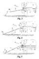
- FIG. 3is a side elevation view of the vehicle access system of FIG. 1 with the ramp partially extended from the vehicle.
- FIG. 4is a side elevation view of the vehicle access system of FIG. 1 with the ramp fully extended from the vehicle.
- FIG. 5is a side elevation view of the vehicle access system of FIG. 1 with the ramp fully extended from the vehicle and the inboard end of the ramp raised to the floor of the vehicle.
- FIG. 6is an enlarged top plan view of the vehicle access system of FIG. 1 with the ramp in the stowed position.
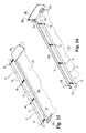
- FIG. 7is an enlarged bottom plan view of the vehicle access system of FIG. 1 with the ramp removed and the drive assemblies located in the deployed position.
- FIG. 8is a perspective view of the frame of the vehicle access system of FIG. 1 with the ramp, carriage and drive assemblies removed therefrom.
- FIG. 9is a sectional view taken through line 9 - 9 of FIG. 8 .
- FIG. 10is an enlarged detailed perspective view of a portion of a control assembly of the vehicle access system of FIG. 1 with a portion of the frame cutaway.
- FIG. 11is an enlarged top plan view of another vehicular access system having a ramp and side barriers depicted with the ramp and side barriers in a stowed low profile position in a frame.
- FIG. 12is a side elevation view of the vehicular access system of FIG. 11 with the ramp partially extended from the vehicle and side barriers in the low profile orientation.
- FIG. 13is a side elevation view of the vehicular access system of FIG. 11 with the ramp fully extended from the vehicle in a deployed position and the side barriers in the low profile orientation.
- FIG. 14is a side elevation view of the vehicular access system of FIG. 11 with the ramp in a vehicle floor level position and the side barriers in a raised safety barrier orientation.
- FIG. 15is a partial perspective view of the inboard end of the ramp of the vehicular access system of FIG. 11 with the ramp in the deployed position and one of the side barriers in the stowed orientation and the other side barrier removed.
- FIG. 16is a partial perspective view of the inboard end of the ramp of the vehicular access system of FIG. 11 with the ramp in the vehicle floor level position and one of the side barriers in the raised safety barrier orientation and the other side barrier removed.
- FIGS. 17 a - 17 dillustrate the orientation between the ramp, actuator, and the side barrier in, respectively, a stowed orientation, a first partially pivoted side barrier position, a second partially pivoted side barrier position, and a raised safety barrier orientation.
- Vehicle access system 10includes a frame 12 having an inboard end 12 a and an outboard end 12 b .
- Frame 12can be mounted to a vehicle V below the vehicle floor F ( FIGS. 3-5 ), below the frame, or in any other position that may occur to those skilled in the art.
- Outboard end 12 bpreferably faces a direction from which vehicle V is to be accessed.
- outboard end 12 bmay face the side of a vehicle V ( FIGS. 3-5 .)
- Outboard end 12 bmay also face any other position, such as, for example, the rear of a vehicle, such as would occur to one skilled in the art.
- a transfer memberis movably mounted to the frame 12 and is sized to provide wheelchair access to the vehicle V from the ground G ( FIGS. 3-5 .)
- the transfer memberis in the form of a ramp 20 that is moveably mounted within frame 12 . While the transfer member is illustrated and described herein with reference to ramp 20 , it should be understood that principles of the present invention also have application with other types of transfer members, such as, for example, a platform for a wheelchair lift. It should further be understood that the drawings of FIGS. 3-5 are not to scale and that both ramp 20 and carriage 18 are sized to fit within frame 12 in the stowed position.
- Access system 10includes a first drive assembly 14 and a second drive assembly 16 interconnected by a linking member 90 (see FIGS. 1 , 2 , 6 and 7 .)
- a control assembly 100is provided to allow selection of the automatic mode or the manual mode. Control assembly 100 is preferably engaged to a portion of the first drive assembly 14 to select the automatic mode of operation and disengaged from that portion to select the manual mode of operation.
- Linking member 90connects first drive assembly 14 to second drive assembly 16 , and control assembly 100 may alternatively engage and disengage a portion of the linking member 90 or drive assembly 16 to select the automatic and manual modes.
- linking member 90maintains drive assemblies 14 and 16 simultaneously in an automatic mode for deploying and stowing ramp 20 using drive motors 52 and 72 , respectively.
- linking member 90maintains drive assemblies 14 , 16 in a manual mode for deploying and stowing the ramp 20 using manual force as may be required, for example, if power to drive motors 52 and 72 is interrupted.
- Frame 12has a first side rail 24 and a second side rail 26 in which wheels 28 of ramp 20 and wheels 30 of carriage 18 are mounted and movable therealong.
- Ramp 20has an inboard end 20 a and an opposite outboard end 20 b .
- carriage 18has an inboard end 18 a and an outboard end 18 b .
- Inboard end 20 a of ramp 20is hingedly attached to outboard end 18 b of carriage 18 by a rocker assembly 32 .
- Ramp 20 and carriage 18are movable within frame 12 between the stowed position ( FIG. 1 ) and the deployed position, ( FIG. 2 ) by first drive assembly 14 and second drive assembly 16 .
- Drive motors 52 and 72 of drive assemblies 14 and 16are powered by a power source P ( FIG. 1 ) which can be the power unit of the vehicle or a separate power unit.
- a power source PFIG. 1
- An operatorcan automatically stow and/or deploy the ramp 20 by selecting deploy and stow switches S 1 and S 2 which are operatively connected to control module 48 .
- An emergency stop switch Eis also operatively connected to control module 48 in order to stop automatic deployment and/or stowing of ramp 20 .
- the operative connection from power unit P, deploy and stow switches S 1 and S 2 and control switch E to control module 48can be accomplished through hardwired connections, radio frequency transmission or any other signal transmission technique known in the art.
- Control module 48is connected to a power cable 46 which is electrically coupled to drive motor 52 of first drive assembly 14 , drive motor 72 of second drive assembly 16 and to lift motor 44 of lifting mechanism 37 .
- Power cable 46is preferably flexible so it travels along with ramp 20 and carriage 30 without kinking or binding as they move inboard and outboard relative to frame 12 .
- Sensorsare preferably provided at or near inboard end 12 a and outboard end 12 b of frame 12 in order to automatically stop movement of ramp 20 when it is fully deployed or stowed and to sequence operation of drive assemblies 14 and 16 with lifting mechanism 37 .
- the sensorsmay be contact sensors, optical sensors, magnetic sensors or any other sensors known in the art.
- rocker assembly 32extends between and is pivotally attached to inboard end 20 a of ramp 20 and outboard end 18 b of carriage 18 .
- Rocker assembly 32includes first rocker shaft 34 a rotatably connected to the outboard end 18 b of carriage 18 and second rocker shaft 34 b rotatably connected to the inboard end 20 a of ramp 20 .
- Rocker shafts 34 a and 34 bare interconnected by a number of struts 36 extending therebetween. The length of struts 36 is preferably adjustable to accommodate differing elevations between the floor F of vehicle V and frame 12 .
- lifting mechanism 37is operable to rotate rocker assembly 32 about first rocker shaft 34 a to thereby raise inboard end 20 a of ramp 20 to the level of floor F of vehicle V providing a smooth transition surface ( FIG. 5 .)
- Lifting mechanism 37includes a bidirectional lift motor 44 mounted in carriage 18 and operable to rotate a pinion 45 connected to the drive shaft (not shown) of motor 44 .
- Pinion 45is located below motor 44 and engages lift gear 42 .
- Lift gear 42is rotatably mounted adjacent to the lower surface of carriage 18 and is driven in a clockwise or counterclockwise direction by motor 44 via pinion 45 .
- Hub 43is mounted concentrically to lift gear 42 and rotates therewith.
- Lifting mechanism 37further includes a lift arm 38 that is pivotally connected at one end to hub 43 at a location spaced away from the center of hub 43 and pivotally connected at its opposite end to a yoke 40 at one end of yoke 40 .
- a spacer 39provides a connection between yoke 40 and carriage 18 while permitting the rocking motion of yoke 40 .
- Yoke 40extends from its connection with lift arm 38 and spacer 39 to a connector 35 that is attached to first rocker shaft 34 a.
- lift arm 38The pivotal connections of lift arm 38 permit lift arm 38 to translate the rotational motion of hub 43 in a plane of rotation substantially parallel to the bottom surface of carriage 18 to the rocking motion of yoke 40 in a substantially perpendicular plane of motion.
- Connector 35translates the rocking motion of yoke 40 into the rotational motion of rocker shaft 34 a about its longitudinal axis which, in turn, raises inboard end 20 a of ramp 20 to the level of floor F of vehicle V as previously described.
- Lift motor 44is reversed to cause pinion 45 to drive lift gear 42 and rotate hub 43 in a clockwise direction ( FIG. 7 .) This moves lift arm 38 away from inboard end 20 a of ramp 20 , rocks yoke 40 away from inboard end 20 a of ramp 20 , and returns inboard end 20 a of ramp 20 to its initial position ( FIG. 4 .)
- Side rails 24 , 26 of frame 12include inwardly facing C-shaped portions 24 a and 26 a sized to received wheels 28 of ramp 20 and wheels 30 of carriage 18 .
- Carriage 18 and ramp 20are connected to one another by rocker assembly 32 , and move together along frame 12 in response to driving forces applied by first drive assembly 14 and second drive assembly 16 .
- First drive assembly 14includes a first bidirectional drive motor 52 mounted in carriage 18 and moveable therewith between a stowed positioned ( FIG. 6 ) and a deployed position ( FIG. 7 .)
- First drive assembly 14also includes a first drive chain 50 .
- First drive motor 52includes a drive gear 64 that is operatively coupled to drive chain 50 to apply a force thereto when motor 52 is powered on.
- a tension sprocket 65is rotatably mounted to carriage 18 and maintains chain 50 in contact with drive gear 64 .
- First outboard sprocket 60is rotatably mounted to frame 12 adjacent outboard end 12 b .
- First inboard sprocket 54 and first double sprocket 56are each rotatably mounted to frame 12 adjacent inboard end 12 a .
- double sprocket 56is positioned between side rail 24 and first inboard sprocket 54 .
- Chain 50is looped around first outboard sprocket 60 , first inboard sprocket 54 , and lower cog 56 a of a first double wheeled sprocket 56 .
- a tension adjuster 58is secured to first inboard sprocket 54 to maintain chain 50 in a taut condition.
- Second drive assembly 16includes a second bidirectional drive motor 72 mounted in carriage 18 and moveable therewith between a stowed position ( FIG. 6 ) and a deployed positions ( FIG. 7 .) Second drive assembly 16 also includes a second drive chain 70 . Second drive motor 72 includes drive gear 84 that is operatively coupled to second drive chain 70 to apply a force thereto when motor 72 is powered on. Tension sprocket 85 is rotatably mounted to carriage 18 and maintains chain 70 in contact with drive gear 84 . Second outboard sprocket 82 is rotatably mounted to frame 12 adjacent outboard end 12 b .
- Second inboard sprocket 74 , second double sprocket 76 , and reversing sprocket 78are rotatably mounted to frame 12 adjacent inboard end 12 a .
- second double wheeled sprocket 76is positioned between second inboard sprocket 74 and reversing sprocket 78
- reversing sprocket 78is positioned between second double wheeled sprocket 76 and side rail 26 .
- a tension adjuster 80is secured to second inboard sprocket 74 to maintain chain 70 in a taut condition.
- Chain 70is looped around second outboard sprocket 82 , second inboard sprocket 74 , reversing sprocket 78 and second double wheeled sprocket 76 .
- chain 70extends around the outboard side of a lower cog 76 a of second double wheeled sprocket 76 thereby permitting both double wheeled sprockets 56 and 76 to rotate in the same direction along with linking member 90 during manual deployment and stowing.
- Linking member 90interconnects first drive assembly 14 with second drive assembly 16 .
- Linking member 90is in the form of a loop chain which is connected around upper cog 56 b of first double sprocket 56 and around upper cog 76 b of second double sprocket 76 .
- Drive chain 50is connected around lower cog 56 a of double sprocket 56 and also around first inboard sprocket 54 and first outboard sprocket 60 , which lie in generally the same horizontal plane as lower cog 56 a .
- Drive chain 70is connected around lower cog 76 a of second double sprocket 76 and also around second inboard sprocket 74 , reversing sprocket 78 , and second outboard sprocket 82 , which lie in generally the same horizontal plane as lower cog 76 a .
- drive chains 50 and 70 and linking member 90are oriented horizontally in the illustrated embodiment to allow the overall height of frame 12 to be reduced.
- control assembly 100is engageable to one of the first drive assembly 14 , the second drive assembly 16 , or linking member 90 to prevent movement of first drive chain 50 , second drive chain 70 , and linking member 90 .
- control assembly 100includes a locking member 102 secured to frame 12 at inboard end 12 a and movable with respect thereto.
- Locking member 102is spring-biased into locking engagement with a locking hub 62 provided on top of first double sprocket 56 by a spring 108 .
- Spring 108extends between and contacts abutment member 112 at one end and slotted wall 114 of locking member 102 at the opposite end.
- Locking member 102is further coupled to a control cable 104 .
- Control cable 104is retained at one end in a cavity 115 of locking member 102 adjacent slotted wall 114 .
- Control cable 104extends through slotted wall 114 , spring 108 , abutment member 112 and side rail 24 .
- cable 104is surrounded by an outer sleeve 110 and is coupled to a handle 106 at its opposite end.
- Handle 106is preferably positioned near outboard end 12 b of frame 12 for easy access by the operator of access system 10 .
- Locking member 102is released from locking hub 62 by pulling on handle 106 , thereby retracting cable 104 and locking member 102 in the direction of arrow R (see FIG. 10 ), and compressing spring 108 .
- Handle 106preferably includes a catch or the like that can be engaged by rotating handle 106 when locking member 102 is disengaged, allowing locking member 102 to be maintained in the disengaged position for manual deployment and stowing of ramp 20 .
- first drive chain 50prevented since first double sprocket 56 is locked. Movement of second drive chain 70 is also prevented because linking member 90 interconnects second double sprocket 76 with first double sprocket 56 . This permits first drive motor 52 and second drive motor 72 to travel along fixed drive chain 50 and 70 respectively when motors 52 and 72 are powered on.
- drive chains 50 and 70 and linking member 90are free to rotate about their respective sprocket wheels. The relative movement of drive chains 50 and 70 is coordinated by linking member 90 and allows manual movement of ramp 20 between the deployed and stowed positions.
- Reversing sprocket 78is provided to reverse the direction of movement of second double sprocket 76 relative to second drive chain 70 when control assembly 100 is disengaged so that double sprockets 56 and 76 rotate in the same direction while drive chains 50 and 70 rotate in opposite directions.
- Linking member 90is thus free to rotate about double sprockets 56 and 76 when control assembly 100 is disengaged allowing ramp 20 to be manually deployed and stowed within frame 12 .
- Access system 10has a central axis A centrally positioned between side rails 24 and 26 of frame 12 and extending between inboard end 12 a and outboard end 12 b ( FIGS. 6 and 7 .)
- linking member 90ensures that both drive chains 50 , 70 will not rotate so that each drive assembly 52 and 72 will move along a fixed chain.
- First drive assembly 14 and second drive assembly 16are on opposite sides of axis A. Motors 52 and 72 of first and second drive assemblies 14 and 16 respectively are spaced generally the same distance from axis A. This configuration provides a concentric driving force to ramp 20 in the automatic mode to prevent ramp 20 from becoming misaligned or otherwise twisted in frame 12 as it moves between the stowed and deployed positions.
- linking member 90rotates about double sprockets 56 and 76 , and thereby coordinates the movement of first drive chain 50 with that of second drive chain 70 .
- Linking member 90ensures that ramp 20 will thus move an equal distance via each drive chain 50 and 70 during manual stowing and deployment of ramp 12 .
- one of the drive motors 52 and 72were to become inoperable, its respective drive gear could be designed to freewheel along the fixed chain while the operable motor deploys and stows ramp 20 . This provides access system 10 with a redundant system for automatically driving the ramp between its stowed and deployed positions.
- FIGS. 11-17there will be described another aspect of the invention directed to a wheelchair ramp having side barriers. While the side barriers are described with reference to a vehicular access system like that of FIGS. 1-10 , it should be understood that the principles associated with the side barriers of the present invention have application with other types of vehicular access systems for wheelchairs, including ramps and lifts.
- FIGS. 11-17there is illustrated vehicular access system 210 that, except as described below, is identical to vehicle access system 10 described above. As such, elements in FIGS. 11-17 identical to a corresponding element in FIGS. 1-10 are designated with the same reference numeral.
- access system 210includes a ramp 220 extending between an inboard end 220 a and an outboard end 220 b .
- a first side barrier 280extends along a first lateral edge or side of ramp 220 and a second side barrier 290 extends along a second lateral edge or side of ramp 220 .
- Side barrier 280has an inboard end 280 a co-extensive with inboard end 220 a of ramp 220 and an opposite outboard end 280 b co-extensive with outboard end 220 b of ramp 220 .
- side barrier 290has an inboard end 290 a co-extensive with inboard end 220 a of ramp 220 and an opposite outboard end 290 b co-extensive with outboard end 220 b of ramp 220 .
- ramp 220is in its stowed position within side rails 24 , 26 of frame 12 and side barriers 280 , 290 are in their stowed orientation to form a low profile arrangement that allows the ramp and side barriers to fit in frame 12 beneath the floor of the vehicle. It is contemplated that side barriers 280 , 290 are pivotally coupled along their respective lateral edge of ramp 220 with a spring hinge that biases the side barriers to their stowed orientation.
- ramp 220is partially deployed from vehicle V, and first side barrier 280 and second side barrier (not shown) remain in their stowed orientation as ramp 220 is extended from frame 12 .
- ramp 220is in a deployed position extending from vehicle V and side barriers 280 , 290 remain in or substantially in their stowed orientations.
- inboard end 220 a of ramp 220is raised to floor level F of vehicle V by rocker assembly 32 as discussed above.
- actuators coupled to rocker assembly 32contact respective ones of the side barriers 280 , 290 as inboard end 220 a is raised to the floor level position, pivoting side barriers 280 , 290 to their raised safety barrier orientation with respect to ramp 220 as shown in FIG. 14 .
- side barriers 280 , 290are spring biased to return toward their stowed orientation shown in FIGS. 11 , 12 and 13 .
- FIGS. 15 and 16there is shown partial perspective views of rocker assembly 32 and a portion of ramp 220 connected therewith.
- Ramp 220is shown in outline form in hidden lines so as to not obstruct the view of rocker assembly 32 .
- rocker assembly 32 and ramp 220are oriented with respect to one another such that inboard end 220 a of ramp 220 is not raised to floor level F; i.e. ramp 220 is in the positions of FIG. 11 , 12 or 13 and rocker assembly 32 is generally horizontally oriented.
- Rocker assembly 32 and ramp 220are rotated in the direction of arrows R to arrive at the ramp/rocker assembly orientation of FIG. 16 , wherein inboard end 220 a is raised to floor level F and rocker assembly 32 is generally vertically oriented, as shown in FIG. 13 .
- Second rocker shaft 34 bhas a first actuator 250 fixedly coupled thereto and extending laterally from one end thereof, and a second actuator 260 fixedly coupled to and extending laterally the other end thereof.
- First actuator 250 and second actuator 260move along with second rocker shaft 34 b as it is raised from its position of FIG. 15 to its position of FIG. 16 by lifting mechanism 37 .
- actuators 250 , 260extend generally parallel to or in generally the same plane as rocker assembly 32 when ramp 220 is in its non-raised position of FIG. 15 .
- actuators 250 , 260follow the rotational movement of second rocker shaft 34 b about first rocker shaft 34 a and are thus oriented transversely to ramp 220 in a generally vertical orientation.
- first side barrier 280is in its stowed orientation and pivoted alongside the upper surface of platform 220 over first actuator 250 (not shown.)
- Second side barrier 290is removed so second actuator 260 can be shown in its stowed orientation.
- Ramp 220includes a recess or cutout 224 in a corner thereof extending partially or completely through ramp 220 .
- Cutout 224is sized to receive second actuator 260 therein so that second actuator 260 is recess below the upper surface of ramp 220 when in its stowed orientation.
- first actuator 250is positioned in cutout 222 of ramp 220 when in its stowed orientation.
- ramp 220 and side barriers 280 , 290can assume a lower profile for stowage in frame 12 than would be possible if actuators 250 , 260 were located between side barriers 280 , 290 and ramp 220 when side barriers 280 , 290 were in their stowed orientation.
- rocker assembly 32is rotatled by lift mechanism 37 to raise inboard end 220 a of ramp 220 to the vehicle floor level.
- Actuators 250 , 260are rotated along with second rocker shaft 34 b from their stowed orientation in cutouts 222 , 224 and into contact with the adjacent side barrier 280 , 290 .
- As actuators 250 , 260are rotated to their vertical orientation, side barriers 280 , 290 are pivoted about their hinged connection with the sides of ramp 220 from their stowed orientation to a raised safety barrier orientation in which side barriers 280 , 290 are generally vertically and transversely oriented with respect to ramp 220 , as shown by side barrier 280 .
- each actuator 250 , 260remains in contact with its adjacent side barrier 280 , 290 to maintain it in the raised safety barrier orientation and resist its normally spring-bias return toward its stowed orientation.
- a number of hinged connections 270 along each side barrierare contemplated.
- Other mechanisms for pivotally connecting the side barriers to the sides of ramp 220are also contemplated as would occur to those skilled in the art.
- Actuator 260includes a first contact portion 262 located towards the center of ramp 220 , and a second contact portion 264 .
- Second contact portion 264is located adjacent the pivotal connection between side barrier 290 and ramp 220 .
- Side barrier 290has a height L 1 above ramp 220 .
- second contact portion 264has a height above ramp 220 that is substantially the same as side barrier 290 .
- First contact portion 262has a height L 2 above ramp 220 that is greater than height L 1 . This allows first contact portion 262 to contact side barrier 290 before second contact portion 264 when actuator 260 is rotated with second rocker shaft 34 b . Further, by offsetting first contact portion 262 toward the center of ramp 220 , first contact portion 262 contacts side barrier 290 at a location spaced from its pivotal connection with ramp 220 , thus creating a greater moment about the pivotal connection between side barrier 290 and ramp 220 than does second contact portion 264 .
- actuator 260is recessed below the upper surface of ramp 220 .
- ramp 22has been moved to its deployed position and can extend downwardly to the ground at an angle relative to rocker assembly 32 .
- the pivoting of ramp 220 relative to rocker assembly 32brings first contact portion 262 into contact with side barrier 290 , but side barrier 290 is not pivoted sufficiently to interfere with movement of ramp 220 into and out of frame 12 .
- the length and positioning of first contact portion 262generates sufficient force to overcome the spring bias of side barrier 290 toward its stowed orientation and to initiate pivoting movement of side barrier 290 toward its raised safety barrier orientation.
- rocker assembly 32is being pivoted from, its horizontal orientation toward its vertical orientation to raise the inboard end of ramp 22 to the vehicle floor level.
- Side barrier 290has been further pivoted toward its raised safety barrier orientation by actuator 260 , and first contact portion 262 is no longer in contact therewith. Pivoting movement of side barrier 290 is further effected only by second contact portion 264 , which thereafter remains in contact with side barrier 290 to maintain it in its raised safety barrier orientation, as shown in FIG. 17 d .
- Actuators 250 , 260are preferably smooth and rounded to facilitate the sliding movement of the side barriers therealong.
- side barrier 290has an overlap portion 292 that extends alongside ramp 220 .
- This overlap 292has a length L 3 that corresponds to the thickness of ramp 220 , and it is contemplated that overlap 292 can be in abutting contact with ramp 220 when side barrier 290 is in its raised safety barrier orientation. If a force indicated by arrow F 1 were to contact side barrier 290 , contact between overlap 292 and ramp 220 would assist the hinges or other pivotal connectors coupling side barrier 290 to ramp 220 in resisting counterclockwise rotation of side barrier 290 . It should be understood that side barrier 280 can be similarly configured.
Landscapes
- Engineering & Computer Science (AREA)
- Transportation (AREA)
- Mechanical Engineering (AREA)
- Vehicle Step Arrangements And Article Storage (AREA)
- Power-Operated Mechanisms For Wings (AREA)
Abstract
Description
Claims (2)
Priority Applications (1)
| Application Number | Priority Date | Filing Date | Title |
|---|---|---|---|
| US11/135,864US7264433B2 (en) | 2001-01-26 | 2005-05-23 | Drive mechanism for a vehicle access system |
Applications Claiming Priority (3)
| Application Number | Priority Date | Filing Date | Title |
|---|---|---|---|
| US26427901P | 2001-01-26 | 2001-01-26 | |
| US10/056,745US7052227B2 (en) | 2001-01-26 | 2002-01-25 | Drive mechanism for a vehicle access system |
| US11/135,864US7264433B2 (en) | 2001-01-26 | 2005-05-23 | Drive mechanism for a vehicle access system |
Related Parent Applications (1)
| Application Number | Title | Priority Date | Filing Date |
|---|---|---|---|
| US10/056,745DivisionUS7052227B2 (en) | 2001-01-26 | 2002-01-25 | Drive mechanism for a vehicle access system |
Publications (2)
| Publication Number | Publication Date |
|---|---|
| US20050215371A1 US20050215371A1 (en) | 2005-09-29 |
| US7264433B2true US7264433B2 (en) | 2007-09-04 |
Family
ID=26735662
Family Applications (2)
| Application Number | Title | Priority Date | Filing Date |
|---|---|---|---|
| US10/056,745Expired - Fee RelatedUS7052227B2 (en) | 2001-01-26 | 2002-01-25 | Drive mechanism for a vehicle access system |
| US11/135,864Expired - Fee RelatedUS7264433B2 (en) | 2001-01-26 | 2005-05-23 | Drive mechanism for a vehicle access system |
Family Applications Before (1)
| Application Number | Title | Priority Date | Filing Date |
|---|---|---|---|
| US10/056,745Expired - Fee RelatedUS7052227B2 (en) | 2001-01-26 | 2002-01-25 | Drive mechanism for a vehicle access system |
Country Status (1)
| Country | Link |
|---|---|
| US (2) | US7052227B2 (en) |
Cited By (24)
| Publication number | Priority date | Publication date | Assignee | Title |
|---|---|---|---|---|
| US20040146385A1 (en)* | 2003-01-29 | 2004-07-29 | Edwards Paul H. | Retractable ramp system for a mobility vehicle |
| US20080187425A1 (en)* | 2007-02-01 | 2008-08-07 | Lift-U, Division Of Hogan Mfg., Inc. | Compact folding slide-out ramp assembly |
| US20080273956A1 (en)* | 2007-05-04 | 2008-11-06 | Lift-U, Division Of Hogan Mfg., Inc. | Counterbalance assembly for a fold out ramp |
| US20110008140A1 (en)* | 2008-02-19 | 2011-01-13 | Strattec Power Access Llc | Power access ramp |
| US20110027054A1 (en)* | 2009-07-28 | 2011-02-03 | Eric Hansen | Front entry power access ramp |
| US7913342B1 (en) | 2009-10-16 | 2011-03-29 | Lift-U, A Division Of Hogan Mfg., Inc. | Counterbalance mechanism for fold out ramp |
| US7913341B1 (en) | 2009-10-16 | 2011-03-29 | Lift-U, A Division Of Hogan Mfg., Inc. | Counterbalance mechanism for fold out ramp |
| US7913343B1 (en) | 2009-10-16 | 2011-03-29 | Lift-U, A Division Of Hogan Mfg., Inc. | Counterbalance mechanism for fold out ramp |
| US20110088177A1 (en)* | 2009-10-16 | 2011-04-21 | Lift- U, A Division Of Hogan Mfg., Inc. | Counterbalance mechanism for fold out ramp |
| US20110146008A1 (en)* | 2009-12-21 | 2011-06-23 | Eric Hansen | Manual access ramp |
| US8057152B1 (en) | 2008-04-11 | 2011-11-15 | White William D | Wheelchair lifting apparatus |
| US8122553B1 (en) | 2011-01-27 | 2012-02-28 | Lift-U, Division Of Hogan Mfg., Inc. | Fold out ramp |
| US8250693B1 (en) | 2011-01-27 | 2012-08-28 | Lift-U, Division Of Hogan Mfg., Inc. | Fold out ramp |
| US8375496B1 (en) | 2011-01-27 | 2013-02-19 | Lift-U, Division Of Hogan Mfg., Inc. | Fold out ramp |
| US8402660B1 (en) | 2009-10-07 | 2013-03-26 | Lift-U, Division Of Hogan Mfg., Inc. | Ramp assembly installation method |
| US8434181B1 (en) | 2009-10-07 | 2013-05-07 | Lift-U, Division Of Hogan Mfg., Inc. | Ramp assembly installation method |
| US8590159B1 (en) | 2009-10-07 | 2013-11-26 | Lift-U, Division Of Hogan Mfg., Inc. | Ramp assembly installation method |
| US8769823B1 (en) | 2009-10-07 | 2014-07-08 | Lift-U, A Division Of Hogan Mfg., Inc. | Ramp assembly installation method |
| US8938837B1 (en) | 2009-10-07 | 2015-01-27 | Lift-U, Division Of Hogan Mfg., Inc. | Ramp assembly installation method |
| USD910938S1 (en)* | 2019-03-26 | 2021-02-16 | Vermont Juvenile Furniture Mfg., Inc. | Pet ramp |
| US11034275B1 (en)* | 2019-10-23 | 2021-06-15 | Clarence Smith | System for a stowable vehicle ramp |
| USD987916S1 (en)* | 2021-07-14 | 2023-05-30 | Hefei Haimai Information Technology Co., Ltd. | Pet climbing platform |
| USD995955S1 (en)* | 2021-10-20 | 2023-08-15 | Ningbo Seedling Industry and Technology Pte. Ltd. | Animal saving escape ramp |
| US11834838B2 (en) | 2019-05-06 | 2023-12-05 | Richard Hoffberg | Wheelchair ramp |
Families Citing this family (21)
| Publication number | Priority date | Publication date | Assignee | Title |
|---|---|---|---|---|
| US7052227B2 (en)* | 2001-01-26 | 2006-05-30 | The Braun Corporation | Drive mechanism for a vehicle access system |
| US20080184500A1 (en)* | 2004-09-10 | 2008-08-07 | The Braun Corporation | Bi-Fold Wheelchair Ramp |
| US20060245883A1 (en)* | 2005-04-11 | 2006-11-02 | Yves Fontaine | Vehicle ramp assembly |
| US7802337B2 (en)* | 2007-10-30 | 2010-09-28 | Marshall Elevator Company | Retractable ramp |
| GB2455764A (en)* | 2007-12-20 | 2009-06-24 | Truck Align Company Ltd | Manually-deployable access ramp assembly |
| US8397329B2 (en)* | 2008-04-07 | 2013-03-19 | Magna Car Top Systems Gmbh | Articulated loading ramp |
| AT513813B1 (en)* | 2013-01-14 | 2014-10-15 | Knorr Bremse Ges Mit Beschränkter Haftung | Sliding step for a rail vehicle or a motor vehicle |
| US8745800B1 (en)* | 2013-07-16 | 2014-06-10 | Lift-U, Division Of Hogan Mfg., Inc. | Fold out ramp |
| FR3009525B1 (en)* | 2013-08-06 | 2015-09-04 | Metalic | MANUAL AND AUTOMATIC DOUBLE RAMP SYSTEM FOR USING A WHEELCHAIR IN A MEANS OF TRANSPORT |
| US9126522B1 (en)* | 2014-01-31 | 2015-09-08 | Vantage Mobility International, Llc | In-floor vehicle ramp |
| FR3020081B1 (en)* | 2014-04-22 | 2016-05-06 | Myd L | DEVICE FOR ASSISTING THE FRACTURE OF AN OBSTACLE BY A VEHICLE |
| JP6521046B1 (en)* | 2017-12-26 | 2019-05-29 | トヨタ自動車株式会社 | Electric vehicle |
| US11097603B1 (en)* | 2018-02-27 | 2021-08-24 | Michael A. Lillo | School bus emergency egress system |
| US11351821B1 (en)* | 2018-03-27 | 2022-06-07 | International Automated System, Inc. | Trailer configured for multiple hitches |
| JP7299070B2 (en)* | 2019-06-03 | 2023-06-27 | 株式会社アイシン | Vehicle slope device |
| WO2021003216A1 (en)* | 2019-07-03 | 2021-01-07 | The Braun Corporation | Ramp assembly with raised ramp position |
| US11548428B2 (en)* | 2019-12-09 | 2023-01-10 | The Braun Corporation | Geared ramp assembly with raised ramp position and side rails and method of use |
| JP7655073B2 (en)* | 2021-05-19 | 2025-04-02 | 株式会社アイシン | Vehicle ramp device |
| JP7615881B2 (en)* | 2021-05-19 | 2025-01-17 | 株式会社アイシン | Vehicle ramp device |
| DE202021106474U1 (en)* | 2021-11-26 | 2023-03-03 | Bode - Die Tür Gmbh | Pedal system for a vehicle |
| WO2024229418A1 (en)* | 2023-05-03 | 2024-11-07 | Node Systems Inc. | Transfer ramp systems for loading, unloading, or transferring cargo between one or more commercial vehicles and associated systems, devices, and methods |
Citations (53)
| Publication number | Priority date | Publication date | Assignee | Title |
|---|---|---|---|---|
| US1024580A (en) | 1911-03-30 | 1912-04-30 | Nat Acme Mfg Co | Roller-clutch. |
| US3983584A (en) | 1974-11-04 | 1976-10-05 | Holecek Otto C | Vehicle invalid lift device |
| US4058228A (en) | 1976-03-04 | 1977-11-15 | Hall Edward L | Passenger vehicle access stair and elevator apparatus |
| US4134504A (en) | 1976-09-21 | 1979-01-16 | Louis Salas | Lift for wheelchairs |
| US4685858A (en) | 1986-02-20 | 1987-08-11 | Transpec Inc. | Vehicle entrance ramp |
| US4759682A (en) | 1987-05-06 | 1988-07-26 | Transpec Inc. | Vehicle entrance ramp |
| US4778328A (en) | 1985-04-24 | 1988-10-18 | Apgar Industries Limited | Tray loader apparatus |
| US4827548A (en) | 1988-05-23 | 1989-05-09 | Transpec Inc. | Vehicle entrance ramp |
| US4850788A (en) | 1987-07-13 | 1989-07-25 | Dickson Industries, Inc. | Ramp assembly for trailers and the like |
| US4909700A (en) | 1989-02-03 | 1990-03-20 | Invercan, Inc. | Lift for wheelchairs |
| US4950123A (en) | 1987-10-19 | 1990-08-21 | Donald Volhard | Retractable bed for truck |
| US4958979A (en) | 1986-11-10 | 1990-09-25 | Ingemar Svensson | Arrangement for a lift adapted to a motor vehicle |
| US4966516A (en) | 1988-11-23 | 1990-10-30 | Vartanian Industries, Inc. | Vehicle access ramp having alternative pivots for stowing |
| US5110252A (en) | 1990-05-24 | 1992-05-05 | Hogan Mfg., Inc. | Wheelchair lift for transit vehicles having elevated passenger compartment floor |
| US5111912A (en) | 1990-12-17 | 1992-05-12 | Hogan Mfg., Inc. | Spring-loaded drive assembly for a wheelchair lift |
| US5133634A (en) | 1990-11-19 | 1992-07-28 | Kidron, Inc. | Ramp lifter device |
| US5160236A (en) | 1991-07-31 | 1992-11-03 | Redding Edward M | Retractable van side door ramp |
| US5186282A (en) | 1992-01-23 | 1993-02-16 | Aging Technologies, Inc. | Vertical transport apparatus |
| US5199150A (en) | 1991-04-08 | 1993-04-06 | Magline, Inc. | Method of constructing a retractable underbody truck ramp |
| GB2224992B (en) | 1988-11-05 | 1993-04-21 | Fretwell P & J Ltd | Vehicles and vehicle lifts |
| DE4134559A1 (en) | 1991-10-19 | 1993-04-29 | Daimler Benz Ag | Ramp for wheelchair access to doorway of vehicle - is raised by electric motor and threaded spindle into position ensuring stepless transition on to floor |
| US5257894A (en) | 1992-04-23 | 1993-11-02 | Grant Howard K | Small vehicle stowable ramp system |
| US5305486A (en) | 1993-06-24 | 1994-04-26 | Wheelers Manufacturing, Inc. | Vehicle passenger boarding system |
| US5331701A (en) | 1993-09-13 | 1994-07-26 | Chase Vearl J | Vehicle chair ramp apparatus |
| US5340267A (en) | 1991-12-17 | 1994-08-23 | Overhead Door Corporation | Retractable vehicle ramp with lift assist |
| US5357869A (en) | 1992-07-10 | 1994-10-25 | Gec Alsthom Transport Sa | Device for facilitating access to a rail vehicle having extendable ramp assembly |
| US5380144A (en) | 1993-09-10 | 1995-01-10 | Care Concepts, Inc. | Deployable vehicle access ramp |
| US5391041A (en) | 1993-01-06 | 1995-02-21 | New Flyer Industries Limited | Hydraulically operated bus ramp mechanism |
| US5393192A (en) | 1993-10-01 | 1995-02-28 | Reb Manufacturing Co., Inc. | Underfloor extendible ramp for vehicles |
| US5636399A (en) | 1995-02-27 | 1997-06-10 | Ricon Corporation | Movable ramp assembly |
| EP0703766B1 (en) | 1993-05-26 | 1997-06-18 | Ricon Corporation | Vehicle lifts |
| US5676515A (en) | 1996-06-03 | 1997-10-14 | Haustein; Norman E. | Low floor vehicle ramp |
| US5775232A (en) | 1997-02-14 | 1998-07-07 | Vapor Corporation | Bridge plate for a mass transit vehicle |
| US5795125A (en) | 1996-07-10 | 1998-08-18 | Walkden; Charles D. | Truck ramp assembly |
| US5815870A (en) | 1996-12-23 | 1998-10-06 | Rom Corporation | Reversible ramp and method for fabricating same |
| US5832555A (en) | 1995-02-27 | 1998-11-10 | Ricon Corporation | Compact moveable ramp assembly |
| US5871329A (en) | 1997-05-21 | 1999-02-16 | U.S. Vantage Company Llc | Powered wheelchair ramp for minivans |
| WO1999012506A1 (en) | 1997-09-05 | 1999-03-18 | Ricon Corporation | Driving mechanism for vehicle lifts |
| US5975830A (en) | 1997-06-11 | 1999-11-02 | Goodrich; Ronald W. | Under floor wheelchair lift |
| ES2137856A1 (en) | 1997-07-07 | 1999-12-16 | Navarro Sebastian Garcia | Improvements to the construction of ramps for the access of disabled (handicapped) people to low-floor vehicles |
| US6010298A (en) | 1998-04-15 | 2000-01-04 | Lift-U Division Of Hogan Mfg., Inc. | Low floor vehicle ramp assembly |
| US6039528A (en) | 1996-12-31 | 2000-03-21 | Lift-U, Division Of Hogan Manufacturing, Inc. | Wheelchair lift with improved outer, inner, and side barriers |
| US6186733B1 (en) | 1998-04-15 | 2001-02-13 | Lift-U, Division Of Hogan Mfg., Inc. | Low floor vehicle ramp assembly |
| US6238188B1 (en) | 1998-08-17 | 2001-05-29 | Carrier Corporation | Compressor control at voltage and frequency extremes of power supply |
| US6343908B1 (en) | 2000-04-21 | 2002-02-05 | New Flyer Industries Limited | Passenger entrance ramp for mass transit vehicle |
| US20020081184A1 (en) | 2000-12-23 | 2002-06-27 | Gerd Sternberg | Power ramp for personal mobility vehicles and method of use |
| US6435804B1 (en) | 1999-05-19 | 2002-08-20 | Mark Hutchins | Lifting apparatus |
| US6470523B1 (en) | 2000-06-21 | 2002-10-29 | Rollon S.P.A. | Foldaway ramp for disabled people in wheelchairs and children's pushchairs for low floor vehicles |
| US6602041B2 (en) | 1999-12-20 | 2003-08-05 | Lift-U, Division Of Hogan Mfg., Inc. | Vehicle flip-out ramp |
| US20040136820A1 (en) | 2003-01-09 | 2004-07-15 | Lift-U, Division Of Hogan Mfg, Inc. | Fld-out ramp having a load dampener |
| US6843635B2 (en) | 2001-04-17 | 2005-01-18 | Lift-U, Division Of Hogan Mfg., Inc. | Vehicle fold-out ramp |
| US6860701B2 (en)* | 2001-08-22 | 2005-03-01 | The Braun Corporation | Wheelchair ramp with side barriers |
| US7052227B2 (en)* | 2001-01-26 | 2006-05-30 | The Braun Corporation | Drive mechanism for a vehicle access system |
Family Cites Families (1)
| Publication number | Priority date | Publication date | Assignee | Title |
|---|---|---|---|---|
| US4658858A (en)* | 1985-10-28 | 1987-04-21 | The United States Of America As Represented By The Secretary Of The Air Force | Electromechanical oxygen regulator valve assembly |
- 2002
- 2002-01-25USUS10/056,745patent/US7052227B2/ennot_activeExpired - Fee Related
- 2005
- 2005-05-23USUS11/135,864patent/US7264433B2/ennot_activeExpired - Fee Related
Patent Citations (67)
| Publication number | Priority date | Publication date | Assignee | Title |
|---|---|---|---|---|
| US1024580A (en) | 1911-03-30 | 1912-04-30 | Nat Acme Mfg Co | Roller-clutch. |
| US3983584A (en) | 1974-11-04 | 1976-10-05 | Holecek Otto C | Vehicle invalid lift device |
| US4058228A (en) | 1976-03-04 | 1977-11-15 | Hall Edward L | Passenger vehicle access stair and elevator apparatus |
| US4134504A (en) | 1976-09-21 | 1979-01-16 | Louis Salas | Lift for wheelchairs |
| US4778328A (en) | 1985-04-24 | 1988-10-18 | Apgar Industries Limited | Tray loader apparatus |
| US4685858A (en) | 1986-02-20 | 1987-08-11 | Transpec Inc. | Vehicle entrance ramp |
| US4958979A (en) | 1986-11-10 | 1990-09-25 | Ingemar Svensson | Arrangement for a lift adapted to a motor vehicle |
| US4759682A (en) | 1987-05-06 | 1988-07-26 | Transpec Inc. | Vehicle entrance ramp |
| US4850788A (en) | 1987-07-13 | 1989-07-25 | Dickson Industries, Inc. | Ramp assembly for trailers and the like |
| US4950123A (en) | 1987-10-19 | 1990-08-21 | Donald Volhard | Retractable bed for truck |
| US4827548A (en) | 1988-05-23 | 1989-05-09 | Transpec Inc. | Vehicle entrance ramp |
| EP0629524A1 (en) | 1988-11-05 | 1994-12-21 | Ricon Uk Limited | Vehicles and vehicle lifts |
| US5556250A (en) | 1988-11-05 | 1996-09-17 | Ricon Corporation | Vehicle lifts |
| GB2224992B (en) | 1988-11-05 | 1993-04-21 | Fretwell P & J Ltd | Vehicles and vehicle lifts |
| EP0446224B1 (en) | 1988-11-05 | 1996-01-03 | Ricon Uk Limited | Vehicles and vehicle lifts |
| US5253973A (en) | 1988-11-05 | 1993-10-19 | Ricon Uk Limited | Vehicles and vehicle lifts |
| US4966516A (en) | 1988-11-23 | 1990-10-30 | Vartanian Industries, Inc. | Vehicle access ramp having alternative pivots for stowing |
| US4909700A (en) | 1989-02-03 | 1990-03-20 | Invercan, Inc. | Lift for wheelchairs |
| US5110252A (en) | 1990-05-24 | 1992-05-05 | Hogan Mfg., Inc. | Wheelchair lift for transit vehicles having elevated passenger compartment floor |
| US5133634A (en) | 1990-11-19 | 1992-07-28 | Kidron, Inc. | Ramp lifter device |
| US5111912A (en) | 1990-12-17 | 1992-05-12 | Hogan Mfg., Inc. | Spring-loaded drive assembly for a wheelchair lift |
| US5199150A (en) | 1991-04-08 | 1993-04-06 | Magline, Inc. | Method of constructing a retractable underbody truck ramp |
| US5160236A (en) | 1991-07-31 | 1992-11-03 | Redding Edward M | Retractable van side door ramp |
| DE4134559A1 (en) | 1991-10-19 | 1993-04-29 | Daimler Benz Ag | Ramp for wheelchair access to doorway of vehicle - is raised by electric motor and threaded spindle into position ensuring stepless transition on to floor |
| US5340267A (en) | 1991-12-17 | 1994-08-23 | Overhead Door Corporation | Retractable vehicle ramp with lift assist |
| US5186282A (en) | 1992-01-23 | 1993-02-16 | Aging Technologies, Inc. | Vertical transport apparatus |
| US5257894A (en) | 1992-04-23 | 1993-11-02 | Grant Howard K | Small vehicle stowable ramp system |
| US5357869A (en) | 1992-07-10 | 1994-10-25 | Gec Alsthom Transport Sa | Device for facilitating access to a rail vehicle having extendable ramp assembly |
| US5391041A (en) | 1993-01-06 | 1995-02-21 | New Flyer Industries Limited | Hydraulically operated bus ramp mechanism |
| EP0703766B1 (en) | 1993-05-26 | 1997-06-18 | Ricon Corporation | Vehicle lifts |
| US5305486A (en) | 1993-06-24 | 1994-04-26 | Wheelers Manufacturing, Inc. | Vehicle passenger boarding system |
| US5380144A (en) | 1993-09-10 | 1995-01-10 | Care Concepts, Inc. | Deployable vehicle access ramp |
| US5331701A (en) | 1993-09-13 | 1994-07-26 | Chase Vearl J | Vehicle chair ramp apparatus |
| US5393192A (en) | 1993-10-01 | 1995-02-28 | Reb Manufacturing Co., Inc. | Underfloor extendible ramp for vehicles |
| US5832555A (en) | 1995-02-27 | 1998-11-10 | Ricon Corporation | Compact moveable ramp assembly |
| US5636399A (en) | 1995-02-27 | 1997-06-10 | Ricon Corporation | Movable ramp assembly |
| US5676515A (en) | 1996-06-03 | 1997-10-14 | Haustein; Norman E. | Low floor vehicle ramp |
| US5795125A (en) | 1996-07-10 | 1998-08-18 | Walkden; Charles D. | Truck ramp assembly |
| US5815870A (en) | 1996-12-23 | 1998-10-06 | Rom Corporation | Reversible ramp and method for fabricating same |
| US6039528A (en) | 1996-12-31 | 2000-03-21 | Lift-U, Division Of Hogan Manufacturing, Inc. | Wheelchair lift with improved outer, inner, and side barriers |
| US6095747A (en) | 1996-12-31 | 2000-08-01 | Lift-U. Division Of Hogan Mfg., Inc. | Wheelchair lift with improved outer, inner, and side barriers |
| US5775232A (en) | 1997-02-14 | 1998-07-07 | Vapor Corporation | Bridge plate for a mass transit vehicle |
| US5871329A (en) | 1997-05-21 | 1999-02-16 | U.S. Vantage Company Llc | Powered wheelchair ramp for minivans |
| US5975830A (en) | 1997-06-11 | 1999-11-02 | Goodrich; Ronald W. | Under floor wheelchair lift |
| ES2137856A1 (en) | 1997-07-07 | 1999-12-16 | Navarro Sebastian Garcia | Improvements to the construction of ramps for the access of disabled (handicapped) people to low-floor vehicles |
| US6102648A (en) | 1997-09-05 | 2000-08-15 | Ricon Corporation | Driving mechanism for vehicle lifts |
| WO1999012506A1 (en) | 1997-09-05 | 1999-03-18 | Ricon Corporation | Driving mechanism for vehicle lifts |
| US6238168B1 (en) | 1998-04-15 | 2001-05-29 | Lift-U, Division Of Hogan Mfg. | Ramp assembly with locking mechanisms |
| US20030007853A1 (en) | 1998-04-15 | 2003-01-09 | Lift-U, Division Of Hogan Mfg. Inc. | Low floor vehicle ramp assembly |
| US6203265B1 (en) | 1998-04-15 | 2001-03-20 | Lift-U, Division Of Hogan Mfg., Inc. | Ramp assembly with lifting levers |
| US6210098B1 (en) | 1998-04-15 | 2001-04-03 | Lift-U, Division Of Hogan Mfg., Inc. | Low floor vehicle ramp assembly |
| US6010298A (en) | 1998-04-15 | 2000-01-04 | Lift-U Division Of Hogan Mfg., Inc. | Low floor vehicle ramp assembly |
| US20010005478A1 (en) | 1998-04-15 | 2001-06-28 | Lift-U, Division Of Hogan Mfg., Inc. | Low floor vehicle ramp assembly |
| US20010008606A1 (en) | 1998-04-15 | 2001-07-19 | Lift-U, Division Of Hogan Mfg., Inc | Low floor vehicle ramp assembly |
| US20010043853A1 (en) | 1998-04-15 | 2001-11-22 | Lift-U, Division Of Hogan Mfg., Inc. | Low floor vehicle ramp assembly |
| US6186733B1 (en) | 1998-04-15 | 2001-02-13 | Lift-U, Division Of Hogan Mfg., Inc. | Low floor vehicle ramp assembly |
| US6409458B1 (en) | 1998-04-15 | 2002-06-25 | Lift-U, Division Of Hogan Mfg., Inc. | Low floor vehicle ramp assembly |
| US6238188B1 (en) | 1998-08-17 | 2001-05-29 | Carrier Corporation | Compressor control at voltage and frequency extremes of power supply |
| US6435804B1 (en) | 1999-05-19 | 2002-08-20 | Mark Hutchins | Lifting apparatus |
| US6602041B2 (en) | 1999-12-20 | 2003-08-05 | Lift-U, Division Of Hogan Mfg., Inc. | Vehicle flip-out ramp |
| US6343908B1 (en) | 2000-04-21 | 2002-02-05 | New Flyer Industries Limited | Passenger entrance ramp for mass transit vehicle |
| US6470523B1 (en) | 2000-06-21 | 2002-10-29 | Rollon S.P.A. | Foldaway ramp for disabled people in wheelchairs and children's pushchairs for low floor vehicles |
| US20020081184A1 (en) | 2000-12-23 | 2002-06-27 | Gerd Sternberg | Power ramp for personal mobility vehicles and method of use |
| US7052227B2 (en)* | 2001-01-26 | 2006-05-30 | The Braun Corporation | Drive mechanism for a vehicle access system |
| US6843635B2 (en) | 2001-04-17 | 2005-01-18 | Lift-U, Division Of Hogan Mfg., Inc. | Vehicle fold-out ramp |
| US6860701B2 (en)* | 2001-08-22 | 2005-03-01 | The Braun Corporation | Wheelchair ramp with side barriers |
| US20040136820A1 (en) | 2003-01-09 | 2004-07-15 | Lift-U, Division Of Hogan Mfg, Inc. | Fld-out ramp having a load dampener |
Cited By (44)
| Publication number | Priority date | Publication date | Assignee | Title |
|---|---|---|---|---|
| US7527467B2 (en)* | 2003-01-29 | 2009-05-05 | The Braun Corporation | Retractable ramp system for a mobility vehicle |
| US20040146385A1 (en)* | 2003-01-29 | 2004-07-29 | Edwards Paul H. | Retractable ramp system for a mobility vehicle |
| US20080187425A1 (en)* | 2007-02-01 | 2008-08-07 | Lift-U, Division Of Hogan Mfg., Inc. | Compact folding slide-out ramp assembly |
| US8505141B1 (en) | 2007-02-01 | 2013-08-13 | Lift-U, Division Of Hogan Mfg., Inc. | Compact folding slide-out ramp assembly |
| US8359691B2 (en) | 2007-02-01 | 2013-01-29 | Lift-U, Division Of Hogan Mfg., Inc. | Compact folding slide-out ramp assembly |
| US20090035112A1 (en)* | 2007-05-04 | 2009-02-05 | Lift-U, Division Of Hogan Mfg., Inc. | Counterbalance assembly for a fold out ramp |
| US20090035111A1 (en)* | 2007-05-04 | 2009-02-05 | Lift-U, Division Of Hogan Mfg., Inc. | Counterbalance assembly for a fold out ramp |
| US7533433B2 (en)* | 2007-05-04 | 2009-05-19 | Lift-U, Division Of Hogan Mfg., Inc. | Counterbalance assembly for a fold out ramp |
| US7533432B2 (en)* | 2007-05-04 | 2009-05-19 | Lift-U, Division Of Hogan Mfg., Inc. | Counterbalance assembly for a fold out ramp |
| US7533434B2 (en)* | 2007-05-04 | 2009-05-19 | Lift-U, Division Of Hogan, Mfg., Inc. | Counterbalance assembly for a fold out ramp |
| US7681272B2 (en)* | 2007-05-04 | 2010-03-23 | Lift-U, Division Of Hogan Mfg. | Counterbalance assembly for a fold out ramp |
| US20090035113A1 (en)* | 2007-05-04 | 2009-02-05 | Lift-U, Division Of Hogan Mfg., Inc. | Counterbalance assembly for a fold out ramp |
| US20080273956A1 (en)* | 2007-05-04 | 2008-11-06 | Lift-U, Division Of Hogan Mfg., Inc. | Counterbalance assembly for a fold out ramp |
| US20110008140A1 (en)* | 2008-02-19 | 2011-01-13 | Strattec Power Access Llc | Power access ramp |
| US8057152B1 (en) | 2008-04-11 | 2011-11-15 | White William D | Wheelchair lifting apparatus |
| US20110027054A1 (en)* | 2009-07-28 | 2011-02-03 | Eric Hansen | Front entry power access ramp |
| US8534979B2 (en) | 2009-07-28 | 2013-09-17 | Strattec Power Access Llc | Front entry power access ramp |
| US8402660B1 (en) | 2009-10-07 | 2013-03-26 | Lift-U, Division Of Hogan Mfg., Inc. | Ramp assembly installation method |
| US8434181B1 (en) | 2009-10-07 | 2013-05-07 | Lift-U, Division Of Hogan Mfg., Inc. | Ramp assembly installation method |
| US8590159B1 (en) | 2009-10-07 | 2013-11-26 | Lift-U, Division Of Hogan Mfg., Inc. | Ramp assembly installation method |
| US8769823B1 (en) | 2009-10-07 | 2014-07-08 | Lift-U, A Division Of Hogan Mfg., Inc. | Ramp assembly installation method |
| US8938837B1 (en) | 2009-10-07 | 2015-01-27 | Lift-U, Division Of Hogan Mfg., Inc. | Ramp assembly installation method |
| US20110088174A1 (en)* | 2009-10-16 | 2011-04-21 | Lift- U, A Division Of Hogan Mfg., Inc. | Counterbalance mechanism for fold out ramp |
| US8020234B2 (en) | 2009-10-16 | 2011-09-20 | Lift-U, A Division Of Hogan Mfg., Inc. | Counterbalance mechanism for fold out ramp |
| US8122552B2 (en) | 2009-10-16 | 2012-02-28 | Lift-U, A Division Of Hogan Mfg., Inc. | Counterbalance mechanism for fold out ramp |
| US7913341B1 (en) | 2009-10-16 | 2011-03-29 | Lift-U, A Division Of Hogan Mfg., Inc. | Counterbalance mechanism for fold out ramp |
| US20110088179A1 (en)* | 2009-10-16 | 2011-04-21 | Lift-U, Division Of Hogan Mfg., Inc. | Counterbalance mechanism for fold out ramp |
| US20110088177A1 (en)* | 2009-10-16 | 2011-04-21 | Lift- U, A Division Of Hogan Mfg., Inc. | Counterbalance mechanism for fold out ramp |
| US20110088175A1 (en)* | 2009-10-16 | 2011-04-21 | Lift- U, A Division Of Hogan Mfg., Inc. | Counterbalance mechanism for fold out ramp |
| US7913342B1 (en) | 2009-10-16 | 2011-03-29 | Lift-U, A Division Of Hogan Mfg., Inc. | Counterbalance mechanism for fold out ramp |
| US20110088176A1 (en)* | 2009-10-16 | 2011-04-21 | Lift- U, A Division Of Hogan Mfg., Inc. | Counterbalance mechanism for fold out ramp |
| US7913343B1 (en) | 2009-10-16 | 2011-03-29 | Lift-U, A Division Of Hogan Mfg., Inc. | Counterbalance mechanism for fold out ramp |
| US20110146008A1 (en)* | 2009-12-21 | 2011-06-23 | Eric Hansen | Manual access ramp |
| US8375496B1 (en) | 2011-01-27 | 2013-02-19 | Lift-U, Division Of Hogan Mfg., Inc. | Fold out ramp |
| US8250693B1 (en) | 2011-01-27 | 2012-08-28 | Lift-U, Division Of Hogan Mfg., Inc. | Fold out ramp |
| US8181300B1 (en) | 2011-01-27 | 2012-05-22 | Lift-U, Division Of Hogan Mfg., Inc. | Fold out ramp |
| US8132281B1 (en) | 2011-01-27 | 2012-03-13 | Lift-U, Division Of Hogan Mfg., Inc. | Fold out ramp |
| US8122553B1 (en) | 2011-01-27 | 2012-02-28 | Lift-U, Division Of Hogan Mfg., Inc. | Fold out ramp |
| USD910938S1 (en)* | 2019-03-26 | 2021-02-16 | Vermont Juvenile Furniture Mfg., Inc. | Pet ramp |
| USD911637S1 (en)* | 2019-03-26 | 2021-02-23 | Vermont Juvenile Furniture Mfg., Inc. | Pet ramp |
| US11834838B2 (en) | 2019-05-06 | 2023-12-05 | Richard Hoffberg | Wheelchair ramp |
| US11034275B1 (en)* | 2019-10-23 | 2021-06-15 | Clarence Smith | System for a stowable vehicle ramp |
| USD987916S1 (en)* | 2021-07-14 | 2023-05-30 | Hefei Haimai Information Technology Co., Ltd. | Pet climbing platform |
| USD995955S1 (en)* | 2021-10-20 | 2023-08-15 | Ningbo Seedling Industry and Technology Pte. Ltd. | Animal saving escape ramp |
Also Published As
| Publication number | Publication date |
|---|---|
| US20020110444A1 (en) | 2002-08-15 |
| US7052227B2 (en) | 2006-05-30 |
| US20050215371A1 (en) | 2005-09-29 |
Similar Documents
| Publication | Publication Date | Title |
|---|---|---|
| US7264433B2 (en) | Drive mechanism for a vehicle access system | |
| US6860701B2 (en) | Wheelchair ramp with side barriers | |
| US5556250A (en) | Vehicle lifts | |
| EP0915778B1 (en) | Under floor wheelchair lift | |
| US6102648A (en) | Driving mechanism for vehicle lifts | |
| US8505141B1 (en) | Compact folding slide-out ramp assembly | |
| US5380144A (en) | Deployable vehicle access ramp | |
| US5110252A (en) | Wheelchair lift for transit vehicles having elevated passenger compartment floor | |
| US6086314A (en) | Foldable platform wheelchair lift | |
| US7326024B2 (en) | Wheelchair lift assembly having a compact stowed profile | |
| AU705929B2 (en) | Locking wheelchair lift | |
| US6837670B2 (en) | Wheelchair access system with stacking platform | |
| US4124099A (en) | Wheelchair lift device | |
| US5425615A (en) | Combination folding stair and platform wheelchair lift | |
| EP0703766B1 (en) | Vehicle lifts | |
| US20030071434A1 (en) | Dual function passenger access system for a vehicle | |
| CA1092553A (en) | Wheelchair lift device | |
| WO2005074406A2 (en) | Wheelchair access system with stacking platform |
Legal Events
| Date | Code | Title | Description |
|---|---|---|---|
| AS | Assignment | Owner name:HARRIS N.A., AS ADMINISTRATIVE AGENT, ILLINOIS Free format text:SECURITY AGREEMENT;ASSIGNOR:THE BRAUN CORPORATION;REEL/FRAME:016735/0295 Effective date:20050901 | |
| AS | Assignment | Owner name:THE BRAUN CORPORATION,INDIANA Free format text:RELEASE BY SECURED PARTY;ASSIGNOR:HARRIS N.A., AS SECURED PARTY;REEL/FRAME:024091/0026 Effective date:20100315 | |
| AS | Assignment | Owner name:JP MORGAN CHASE BANK, N.A.,INDIANA Free format text:SECURITY AGREEMENT;ASSIGNOR:THE BRAUN CORPORATION;REEL/FRAME:024140/0001 Effective date:20100312 | |
| FPAY | Fee payment | Year of fee payment:4 | |
| REMI | Maintenance fee reminder mailed | ||
| LAPS | Lapse for failure to pay maintenance fees | ||
| STCH | Information on status: patent discontinuation | Free format text:PATENT EXPIRED DUE TO NONPAYMENT OF MAINTENANCE FEES UNDER 37 CFR 1.362 | |
| FP | Lapsed due to failure to pay maintenance fee | Effective date:20150904 | |
| AS | Assignment | Owner name:THE BRAUN CORPORATION, INDIANA Free format text:RELEASE BY SECURED PARTY;ASSIGNOR:JPMORGAN CHASE BANK, N.A.;REEL/FRAME:036927/0686 Effective date:20151030 | |
| AS | Assignment | Owner name:JPMORGAN CHASE BANK, N.A. AS ADMINISTRATIVE AGENT, NEW YORK Free format text:SECURITY INTEREST;ASSIGNORS:THE BRAUN CORPORATION;B & D INDEPENDENCE, LLC;VALEDA COMPANY, LLC;AND OTHERS;REEL/FRAME:067310/0911 Effective date:20240503 |