US7264050B2 - Method and apparatus for controlling wellbore equipment - Google Patents
Method and apparatus for controlling wellbore equipmentDownload PDFInfo
- Publication number
- US7264050B2 US7264050B2US10/936,438US93643804AUS7264050B2US 7264050 B2US7264050 B2US 7264050B2US 93643804 AUS93643804 AUS 93643804AUS 7264050 B2US7264050 B2US 7264050B2
- Authority
- US
- United States
- Prior art keywords
- control
- parameter
- equipment
- monitoring unit
- monitoring
- Prior art date
- Legal status (The legal status is an assumption and is not a legal conclusion. Google has not performed a legal analysis and makes no representation as to the accuracy of the status listed.)
- Expired - Lifetime, expires
Links
- 238000000034methodMethods0.000titleclaimsabstractdescription29
- 238000012544monitoring processMethods0.000claimsabstractdescription139
- 238000004891communicationMethods0.000claimsabstractdescription59
- 230000005540biological transmissionEffects0.000claimsdescription19
- 238000011156evaluationMethods0.000claimsdescription17
- 230000008859changeEffects0.000claimsdescription7
- 239000000835fiberSubstances0.000claimsdescription7
- 241000239290AraneaeSpecies0.000claimsdescription3
- 230000008901benefitEffects0.000description5
- 238000006243chemical reactionMethods0.000description3
- 230000004044responseEffects0.000description3
- 230000000712assemblyEffects0.000description2
- 238000000429assemblyMethods0.000description2
- 238000001514detection methodMethods0.000description2
- 238000004880explosionMethods0.000description2
- 238000002789length controlMethods0.000description2
- 238000012423maintenanceMethods0.000description2
- 230000005055memory storageEffects0.000description2
- 239000003129oil wellSubstances0.000description2
- 239000003381stabilizerSubstances0.000description2
- 238000012935AveragingMethods0.000description1
- 238000004040coloringMethods0.000description1
- 238000013480data collectionMethods0.000description1
- 238000013461designMethods0.000description1
- 238000005553drillingMethods0.000description1
- 239000011152fibreglassSubstances0.000description1
- 239000012530fluidSubstances0.000description1
- 238000009434installationMethods0.000description1
- 230000010354integrationEffects0.000description1
- 238000005259measurementMethods0.000description1
- 238000012986modificationMethods0.000description1
- 230000004048modificationEffects0.000description1
- 230000036316preloadEffects0.000description1
- 230000008569processEffects0.000description1
- 238000012545processingMethods0.000description1
- 238000012552reviewMethods0.000description1
- 230000001360synchronised effectEffects0.000description1
Images


Classifications
- E—FIXED CONSTRUCTIONS
- E21—EARTH OR ROCK DRILLING; MINING
- E21B—EARTH OR ROCK DRILLING; OBTAINING OIL, GAS, WATER, SOLUBLE OR MELTABLE MATERIALS OR A SLURRY OF MINERALS FROM WELLS
- E21B44/00—Automatic control systems specially adapted for drilling operations, i.e. self-operating systems which function to carry out or modify a drilling operation without intervention of a human operator, e.g. computer-controlled drilling systems; Systems specially adapted for monitoring a plurality of drilling variables or conditions
- E—FIXED CONSTRUCTIONS
- E21—EARTH OR ROCK DRILLING; MINING
- E21B—EARTH OR ROCK DRILLING; OBTAINING OIL, GAS, WATER, SOLUBLE OR MELTABLE MATERIALS OR A SLURRY OF MINERALS FROM WELLS
- E21B19/00—Handling rods, casings, tubes or the like outside the borehole, e.g. in the derrick; Apparatus for feeding the rods or cables
- E21B19/16—Connecting or disconnecting pipe couplings or joints
- E21B19/165—Control or monitoring arrangements therefor
- H—ELECTRICITY
- H04—ELECTRIC COMMUNICATION TECHNIQUE
- H04N—PICTORIAL COMMUNICATION, e.g. TELEVISION
- H04N7/00—Television systems
- H04N7/18—Closed-circuit television [CCTV] systems, i.e. systems in which the video signal is not broadcast
- H04N7/183—Closed-circuit television [CCTV] systems, i.e. systems in which the video signal is not broadcast for receiving images from a single remote source
- H04N7/185—Closed-circuit television [CCTV] systems, i.e. systems in which the video signal is not broadcast for receiving images from a single remote source from a mobile camera, e.g. for remote control
Definitions
- This inventionrelates to a method and an apparatus for remotely controlling and/or monitoring well bore equipment arranged at oil or gas wells, and relate more particularly but not exclusively to a method for remotely controlling and/or monitoring at least one parameter of preferably mechanized well bore equipment arranged at oil or gas wells and to a rig control and monitoring system.
- An oil or gas wellincludes a well bore extending from the surface of the earth to some depth therebelow.
- different equipmentis sometimes necessary within the well bore and at the surface of the well.
- Such equipmentis used for drill pipe handling, pressure control, tubing work, casing handling, and well installation.
- drill pipe handling, pressure control, tubing work, casing handling, and well installationis used for drill pipe handling, pressure control, tubing work, casing handling, and well installation.
- Such equipmenthas been manually operated.
- the industry trendis toward mechanization and automation of such equipment where possible.
- mechanized rig systemsimprove rig flow operations by helping operators install tubing, casing, and control pipe more safely and efficiently during demanding drilling operations.
- Such a mechanized rig systemreduces the time needed for pipe handling, make-up and break out of pipe connections.
- Other mechanized equipment for well boresprovides efficient means of automatic tubular handling and running.
- Other mechanized well bore equipmentincludes tongs, like tubing tongs, basing tongs, fiberglass pipe tongs, and drill pipe tongs for making up tubular connections.
- Tongsused in systems for placing a predetermined torque on a connection as well as tongs having independent rotation devices disposed therein.
- some tongsinclude maneuvering devices that may be rail mounted are designed to suspend casing, tubing or drill type tongs from a frame.
- devicesare routinely further automated and mechanized through the use of sensors for controlling and monitoring equipment and also for monitoring parameters of such equipment, like temperature, pressure, fluid flow, and torque, for example.
- a corresponding sensoris generally connected to a measuring device which is part of or at least directly connected to some kind of computer terminal.
- the data from the sensoris transmitted to such measuring device and from this to the computer terminal.
- the measuring devicecomprises for example, a micro controller with customized software that may be used for collecting the data from the sensor and to transmitting it to the computer terminal.
- the datais processed and then displayed as a graphical display, like a bar graph, for example.
- the corresponding computer terminal used for evaluating the data collected from the sensorsis typically some distance from the mechanized well bore equipment or the other equipment of the well whose parameters are monitored. Consequently, the result of the evaluation of the data is not directly useable for controlling and adjusting the equipment, and a separate communication channel is necessary, like a phone call or even by voices raised above the level of background noise.
- One aspect of the present inventionis a method for remotely controlling and/or monitoring at least one parameter of well bore equipment comprising: collecting data corresponding to the at least one parameter by a sensor module monitoring the at least one parameter of the well bore equipment: transmitting the collected data to a remote control/monitoring unit via a communication link; analyzing the collected data to determine if the parameter is within predefined limits; if the parameter is not within predefined limits, then transmitting control data from the control/monitoring unit to the well bore equipment for modifying the operation of the well operation equipment so that the parameter will conform to the predefined limits or stopping operation of the wellbore equipment.
- a rig control and monitoring systemcomprises at least one piece of mechanized well bore equipment, comprising a sensor module; a remote control/monitoring unit connected with the well bore equipment by a communication link, wherein the control/monitoring unit comprises a display means and/or a storage means.
- FIG. 1is a view of a rig control and monitoring system.
- FIG. 2is a view of a communication structure with corresponding communication links used according to FIG. 1 .
- FIG. 3illustrates an alternative embodiment of a rig control and monitoring system according to the present invention.
- FIG. 4is a more detailed view of the communication structure used by the rig control and monitoring system according to FIG. 3 .
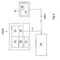
- FIG. 1is a view of one embodiment of a rig control and monitoring system 11 according to the invention.
- the rig control and monitoring system 11includes a piece of well bore equipment 1 , which in turn includes a rig control system 15 .
- a system 15is typically used for operating a tong 14 which holds a tube or casing 28 .
- One sensor module 6is assigned to this system 15 .
- the corresponding parameters monitored by the sensor module 6are typically torque and turns.
- a system used for data collection by the sensor module or modules 6is a torque—turn and torque—time monitoring means and in particular a joint analyzed make-up (JAM) system, available from Weatherford International of Houston, Tex., for monitoring torque, turns, elapsed time and numbers of rotation of a tong.
- JAMjoint analyzed make-up
- a load cell for torque measuring and a turn countermay transmit data to a universal data acquisition and control system 2 as a generalized measuring device.
- the sensor module 6may also be assigned to any kind of equipment used at a gas or oil well like tubing or casing tongs, drill pipe tongs, remotely operated tongs, tong positioning systems, make-up and break out tools, systems for automatic tubular handling and running, connection leak detection systems, slips, spiders, pressure control equipment, packers, etc.
- the parameter monitored by the corresponding sensor modulemay be for example, torque, number of turns, elapsed time, pressure, temperature, flow, etc.
- the sensor module 6may also be adapted to detect a leak of the tubing or casing or any other part of the equipment.
- the rig control system 15is normally used to improve the rig operations for installing tubing, casing, drill tools, and string make-up. Such rig control system 15 allows the running of tubulars without exposing personnel in the derrick to dangerous conditions.
- the rig control system 15may include mechanized components, such as a Power FrameTM available from Weatherford International, or a Torq WinderTM, also available from Weatherford International.
- the Power FrameTMis an automatic tubular handling and running, remotely controlled hydraulic rail-mounted system.
- the Torq WinderTMis a system which makes-up and breaks out drill pipe, drill collars, drill bits, stabilizers and bottom hole assemblies.
- the data corresponding to the measured parameteris submitted by the sensor module 6 to an individual control means 10 assigned to the corresponding well bore equipment 1 . It is also possible that the corresponding data is directly submitted by communication link 4 to the universal data acquisition and control system 2 .
- FIG. 1there is only one piece of well bore equipment 1 and one sensor module 6 assigned thereto.
- the different sensor modules 6 at the multiple locationsmay be the same sensor modules used for example, for measuring pressure.
- the communication link 4may be a wire transmission link or a field bus link. Examples for such a field bus are Profibus, Interbus, CANBus, LightBus or even other communication links as RS232 or RS485 or others.
- the data from the sensor moduleis advantageously transmitted to the universal data acquisition control system via a wireless transmission.
- it may be advantageous to use a wire transmissionfor example, when there would be a number of interferences in view of a wireless transmission caused by other wireless transmissions used at the well.
- the communication link 4 to the sensor module 6 from the universal data acquisition and control unit 2may also be any of the means described below for communication link 8 .
- One universal data acquisition and control system 2 suitable for use in this inventionis a HiPerTM control system available from Weatherford, which is an operating platform suitable for all mechanized rig systems in which the corresponding components can be operated remotely by utilizing this system.
- the applicantpreferably uses the HiPerTM control system for operating mechanized rig and well bore equipment.
- This control system of the applicantmay be used as the universal data acquisition and control system 2 .
- this applicant's control systemis already adapted for controlling and adjusting the operation of the corresponding equipment such that by the communication link to the control/monitoring unit, an immediate reaction and modifying or adjusting of the operation of the equipment is possible to maintain a corresponding parameter within defined limits.
- a bus transmission meanswith corresponding interfaces provided at the control system and at the unit.
- Examples for such bus transmission meansare Ethernet, field bus, RS232, RS485, etc.
- a corresponding field busmay be for example a profibus, interbus, CAN bus, etc.
- the communication linkis realized by Ethernet, such a connection may be a TCP/IP connection.
- a fiber optic transmission meansIn the North Sea, for example, a corresponding fiber optic backbone can be used as such a fiber optic transmission means.
- a further possibilityis a wireless transmission means as for example a radio transmission link which may also be realized by a satellite communication link.
- a common characteristic of such transmission means or communication linksshould be that they are high data rate communication links.
- any known type of modulation of the datamay be used, as frequency modulation, amplitude modulation, etc.
- the communication links 4 , 8are fully duplexed such that data may be easily transmitted in both directions not only between sensor module 6 and data acquisition and control system 2 , but also between control/monitoring unit 3 and the data acquisition and control system.
- the collected datais transmitted by the communication link 8 to the remote control/monitoring unit 3 , which may be a distance from sensor module 6 .
- the operatormay be located onshore when the well site is offshore.
- the remote control/monitoring unit 3may be, for example, a laptop computer. This laptop 3 serves as a display unit and may also serve as an evaluation unit for the data received from the universal data acquisition and control system 2 .
- the corresponding control/monitoring unit 3may display, for example different graphs of torque/time and torque/turns may be displayed.
- the corresponding sensor module 6is not directly connected to the computer terminal or corresponding control/monitoring unit 3 . Consequently, this terminal unit 3 can be arranged at any place relative to the corresponding sensor module 6 , which means the unit may be arranged onshore and used for example for offshore wells. Also, the corresponding personnel can be located remotely from the well and all the equipment such that safety is increased. Additionally, work for the personnel is simplified as there is no longer a need to work in a noisy environment with exposure to the weather elements. Also, it is also no longer necessary to meet the strict requirements for devices arranged quite near to the well, as fireproof, intrinsically safe, explosion proof, etc.
- the universal data acquisition control system 2may be connected to a plurality of sensor modules 6 for collecting corresponding data. Since the collected data is transmitted from the universal data acquisition control system 2 to the control/monitoring unit 3 , there is no particular measuring device assigned to the unit or computer terminal 3 , but there is a general and universal data acquisition and control system 2 used for collecting data from the corresponding sensor modules.
- corresponding sensor modules 6 of this system at different locationsbe served by only one control/monitoring unit 3 realized by a corresponding computer.
- the specific data collected from these sensor modules 6 from one locationcan be shared with the others in order to provide a complete make-up history at the well center.
- Thisenables the pre-assembly of pipe in stands at a mouse hole position and forwarding this stand to well center and also forwarding the corresponding JAM data as well to well center in order to track Tally numbering or Tally length control, wherein string length control is important for setting a packer.
- data from a plurality of sensor modulesis displayed and/or stored by the control/monitoring unit 3 wherein the data may be displayed on one screen in different windows or in different pull-down windows or may also be displayed on different screens that have to be selected.
- the communication links 4 , 8are fully duplex, and it is also possible to transmit control data from the remote control/monitoring unit 3 to the universal data acquisition and control system 2 .
- the control datamay then be used by the universal data acquisition and control system 2 to modify or adjust well bore equipment 1 such that the parameter measured by sensor module 6 is within predefined limits or such control data may be used to stop the operation of the corresponding well bore equipment 1 in case it is not possible that the equipment may be controlled to keep the parameter within the predefined limits.
- the corresponding control data received by the universal data acquisition and control system 2may be transmitted to a corresponding valve control block assigned to the corresponding well bore equipment 1 is operated via system 15 for control of tong speed and torque.
- the universal data acquisition and control system 2provides an on-site access to the collected data or the received control data. By this on-site access, it is possible to check the data directly at the universal data acquisition and control system 2 or to change the received control data to influence the adjustment or modification of the operation of the equipment 1 that would otherwise be initialized by these control data received from the control/monitoring unit 3 .
- Another universal data acquisition and control system 9may be connected to system 2 through a communication link 17 , and may also be used to remotely control the well bore equipment 1 from another computer or laptop 16 wherein the corresponding operator is arranged offshore, i.e. on rig site. This operator directly controls the well bore equipment 1 and may also receive the control data from the remote control/monitoring unit 3 for adjusting his operation in response to the received control data. Alternatively, It possible to connect at least one more control/monitoring unit 3 to the universal data acquisition and control system 2 , wherein this additional unit may be used as a back-up unit or to display the corresponding data to personnel at a different location.
- the rig control system 15may be a separate control system different from the universal data acquisition and control system 2 but also be used for receiving control data from the control/monitoring unit 3 . It is also possible that the rig control system 15 is used as a separate universal data acquisition and control system 2 . The good or bad make-up may then be immediately notified and forwarded to the rig control system 15 via the corresponding communication link such that no shouting, no phone calls are necessary as with a separate JAM-equipment not using universal data acquisition and control system 2 and corresponding communication links between same and the sensor module 6 and the control/monitoring unit 3 .
- a further advantage of the inventionis that the universal data acquisition and control system 2 or the separate control system 15 may be integrated on-site, i.e. rig's individual control means. By such an integration, the universal data acquisition and control system 2 or the separate control system 15 is arranged on a corresponding offshore rig.
- FIG. 2is a more detailed view of the communication structure used by the rig control and monitoring system 11 according to FIG. 1 .
- the universal data acquisition and control system 2comprises for example a memory storage means 5 which may be used for immediate storage of data collected from one or more sensor modules 6 .
- this memory storage means 5may also be used for storing other data of the well bore equipment 1 or for storing control data received from the remote control/monitoring unit 3 .
- the universal data acquisition and control system 2further comprises a programmable logic control device 21 and interfaces 24 and 25 for the corresponding communication links to the remote control/monitoring unit 3 and the sensor module 6 or well bore equipment 1 and further remote control means 16 .
- the communication link between laptop 16 or sensor module 6 /well bore equipment 1 and universal data acquisition and control system 2is realized by a field bus 17 which may be a Profibus, Interbus, RS232, RS485 or others.
- the other interface 24is used for realizing the communication link to the remote control/monitoring unit 3 by Ethernet 8 .
- this communicationis a radio transmission via satellite, a fiber optic transmission, etc.
- the remote control/monitoring unit 3also comprises another interface 20 and further a display means 12 and a storage means 13 .
- the display means 12is used for visualizing the evaluated data received from the universal data acquisition and control system 2 as a graph, a table, etc.
- a corresponding evaluation module 22is stored in the remote control/monitoring unit, wherein, the evaluation module 22 may be provided on any kind of at least readable storage means.
- the evaluation module 22may evaluate the received data and display it as a graph, a table, or some other illustration. It is also possible that the evaluation module 22 is usable for more than one software module and also for different parameters.
- a second evaluation modulemay be loaded into the control/monitoring unit 3 wherein such evaluation module may be realized by software on a memory means readable by the unit.
- FIG. 2there is not only an Ethernet communication link between universal data acquisition and control system 2 and the remote control/monitoring unit 3 , but also between control system 2 and at least one further supervising means 26 . This may be arranged at a different location and may be used for remote debugging, supervising, collecting data for maintenance, etc.
- the corresponding or general communication link 8such as Ethernet, between remote control/monitoring unit 3 and universal data acquisition and control system is also used for forwarding an interpretation of the data to the corresponding rig control system 15 or well bore equipment 1 such that it can be immediately decided if the parameters are in predefined limits.
- the inventionit is in particular possible to remove personnel from the well bore or well center area on the rig without interruption of the operation of the well bore equipment due to safety reasons as there may be an intermediate response back from the remote control/monitoring unit 3 to the universal data acquisition and control system 2 and further to the corresponding well bore equipment 1 or rig control system 15 . Consequently, there is not only real time data acquisition and evaluation according to the method of the invention but also real time operation of the corresponding well bore equipment or rig control system to react on the evaluation of the collected data.
- the universal data acquisition and control systemBecause of the plurality of sensor modules, the universal data acquisition and control system, additional control system, control/monitoring units, it is of advantage when all these devices are synchronized.
- itmay comprise a programmable logic control means.
- FIG. 3illustrates an alternative embodiment of a rig control and monitoring system 211 according to the present invention.
- the rig control and monitoring system 211includes a piece of well bore equipment 201 , for example, a Power FrameTM, which is an automatic tubular handling and running, remotely controlled hydraulic rail-mounted system, available from Weatherford International of Houston, Tex., or a Torq WinderTM, which makes-up and breaks out drill pipe, drill collars, drill bits, stabilizers and bottom hole assemblies, also available from Weatherford International.
- a Power FrameTMwhich is an automatic tubular handling and running, remotely controlled hydraulic rail-mounted system, available from Weatherford International of Houston, Tex.
- Torq WinderTMwhich makes-up and breaks out drill pipe, drill collars, drill bits, stabilizers and bottom hole assemblies, also available from Weatherford International.
- the piece of well bore equipment 201may also include any kind of equipment used at a gas or oil well like tubing or casing tongs, drill pipe tongs, remotely operated tongs, tong positioning systems, make-up and break out tools, systems for automatic tubular handling and running, connection leak detection systems, slips, spiders, pressure control equipment, packers, etc.
- the well bore equipment 201includes a tong 214 which holds a tube or casing 228 .
- the piece of well bore equipment 201includes an individual control system 215 , typically used for operating the well bore equipment 201 .
- the individual control system 215may include a valve control block (not shown) for control of tong speed and torque.
- the individual control system 215further includes a sensor module 206 , which in this case, is capable of monitoring torque and turns.
- the sensor module 206may also be capable of monitoring elapsed time, pressure, temperature, flow, etc., depending on the type of well bore equipment 201 used.
- the sensor modulemay also be adapted to detect a leak of the tubing or casing or any other part of the equipment.
- the data corresponding to the measured parameteris submitted from the sensor module to a remote control/monitoring unit 203 via a first communication link 208 .
- the remote control/monitoring unit 203may be located at a considerable distance from the piece of well bore equipment 1 .
- the operatormay be located onshore when the well site is offshore.
- the remote control/monitoring unitmay be also be located on-site relative to the piece of well bore equipment 1 .
- the data corresponding to the measured parametermay also be submitted from the sensor module to a local control/monitoring unit 216 via a second communication link 217 , especially if the remote control unit 203 is located off-site.
- the local control/monitoring unit 216may be located proximate the piece of wellbore equipment 201 relative to the remote control/monitoring unit 203 , and will usually be located on-site.
- the operator operating the local control/monitoring unit 216may directly control the piece of well bore equipment 201 instead of the remote control/monitoring unit 203 having direct control. In that case, the local operator would receive the control data from the remote control/monitoring unit 203 and relay it to the individual control unit of the piece of well bore equipment 201 .
- Either of the control/monitoring units 203 , 216may be integrated with other rig control systems (not shown).
- the remote control/monitoring unit 203may be connected to many pieces of well bore equipment at a single site, multiple sites, or both.
- the communication links 208 , 217may be hard wired or wireless.
- the communication links 208 , 217may be realized by bus transmission means with corresponding interfaces provided at the individual control system 215 and at the respective control/monitoring units 203 , 229 .
- Examples for such bus transmission meansare Ethernet, field bus, RS232, RS485, etc.
- a corresponding field busmay be for example a profibus, interbus, CAN bus, etc.
- the communication linkis realized by Ethernet, such a connection may be a TCP/IP connection.
- the communication links 208 , 217are fully duplex and are capable of handling high data rates.
- the communication links 208 , 217may also be realized by satellite or fiber optics.
- the control/monitoring units 203 , 229serve as a display unit and may also serve as an evaluation unit for the data received from the sensor 206 .
- the control/monitoring units 203 , 229may be computers, such as desktops or laptops.
- the computersmay be running a software package, such as JAM (joint analyzed makeup) monitoring software, also available from Weatherford International.
- JAM softwareis used to monitor torque, turns and rotations per minute of the tong to ensure that all tubing and casing connections confirm to a manufacturer's specification.
- An operator at each of the control/monitoring units 203 , 229may review the data from the sensor module 206 .
- the respective operatormay cause one of the control/monitoring units 203 , 229 to issue control data to the individual control system 215 which will then modify or adjust well bore equipment 201 such that the parameter will conform to the predefined limits.
- the respective operatormay cause one of the control/monitoring units 203 , 229 to issue control data to the individual control system 215 which will then stop operation of the corresponding well bore equipment 201 if he determines it is not possible to control the equipment to keep the parameter within the predefined limits.
- FIG. 4is a more detailed view of the communication structure used by the rig control and monitoring system 11 according to FIG. 3 .
- the control/monitoring units 203 , 229may each comprise, for example, a storage means 213 which may be used for immediate storage of data collected from one or more sensor modules 206 . This storage means 213 may also be used for storing other data of the well bore equipment 201 or for storing control data issued by a respective one of the control/monitoring units 203 , 229 .
- the control/monitoring units 203 , 229may each further comprise a programmable logic control device 221 and an interface 225 for the corresponding communication links to the piece of well bore equipment 201 .
- the control/monitoring units 203 , 229each also comprise display means 212 , which may be used for visualizing the evaluated data received from the sensor 206 as a graph, a table, etc.
- display means 212may be used for visualizing the evaluated data received from the sensor 206 as a graph, a table, etc.
- a corresponding evaluation module 222is stored in the control/monitoring unit, wherein, the evaluation module 222 may be provided on any kind of at least readable storage means.
- the rig control and monitoring system 211may further comprise at least one further supervising means 226 .
- the supervising means 226may be arranged at a different location and may be used for remote debugging, supervising, collecting data for maintenance, etc.
- informationcan be displayed in other useful ways, especially information related to operating variables of automated equipment on a rig floor.
- informationcan be displayed in other useful ways, especially information related to operating variables of automated equipment on a rig floor.
- utilizing the hardware and software described hereinit is possible to display items in a three dimensional format whereby variables like torque, turns, and time are independently illustrated along with their relationship to each other.
- this three dimensional formatit is also possible to dissect the image to give a snap shot of any one or two of the variables at any particular time. In this manner, the make up of a joint, for instance can be analysed at any time.
- the applied torque and rotation in making up a shouldered tubular connectionare measured at regular intervals throughout a pipe connection makeup.
- the rate of change of torque with rotation(derivative) is calculated for each set of measurements.
- These three valuesare then compared either continuously or at selected rotational positions, with minimum and maximum acceptable predetermined values, and a decision made whether to continue rotation or abort the makeup.
- the derivative(rate of change of torque) is compared with predetermined threshold values to determine seal and shoulder contact points. The change in torque and rotation between these two detected contact points is checked to ensure that the change is within a predetermined acceptable range.
- a predetermined torque value and/or rotation valueis added to the measured torque and/or rotation values, respectively, at shoulder contact and rotation continued until this calculated value(s) is reached.
- the application of torqueis terminated and the reverse rotation of a tubing length is monitored as the connection relaxes. If the relaxation is within an acceptable predetermined range and the above conditions are met then the makeup is considered acceptable.
Landscapes
- Engineering & Computer Science (AREA)
- Geology (AREA)
- Life Sciences & Earth Sciences (AREA)
- Mining & Mineral Resources (AREA)
- Physics & Mathematics (AREA)
- Environmental & Geological Engineering (AREA)
- Fluid Mechanics (AREA)
- General Life Sciences & Earth Sciences (AREA)
- Geochemistry & Mineralogy (AREA)
- Mechanical Engineering (AREA)
- Multimedia (AREA)
- Signal Processing (AREA)
- Arrangements For Transmission Of Measured Signals (AREA)
- Selective Calling Equipment (AREA)
Abstract
Description
Claims (35)
Priority Applications (9)
| Application Number | Priority Date | Filing Date | Title |
|---|---|---|---|
| EP05270072AEP1637695A1 (en) | 2000-09-22 | 2001-09-17 | Methods and apparatus for remote monitoring and control. |
| US10/936,438US7264050B2 (en) | 2000-09-22 | 2004-09-08 | Method and apparatus for controlling wellbore equipment |
| US10/977,506US20050161260A1 (en) | 2000-09-22 | 2004-10-29 | System for communicating information between a rig location and a cpmputer network and methods using the system |
| EP05019284AEP1635032A1 (en) | 2004-09-08 | 2005-09-06 | Method and apparatus for controlling surface well equipment |
| CA002518347ACA2518347A1 (en) | 2004-09-08 | 2005-09-06 | Method and apparatus for controlling wellbore equipment |
| NO20054173ANO20054173L (en) | 2004-09-08 | 2005-09-07 | Method and apparatus for controlling source equipment |
| CA002522450ACA2522450A1 (en) | 2000-09-22 | 2005-10-07 | System for communicating information between a rig location and a computer network and methods using the system |
| EP05109496AEP1653044A3 (en) | 2000-09-22 | 2005-10-12 | System for communicating information between a rig location and a computer network and methods using the system |
| NO20054972ANO20054972L (en) | 2000-09-22 | 2005-10-26 | System for communication between a rig location and a computer network, as well as methods for using the system |
Applications Claiming Priority (3)
| Application Number | Priority Date | Filing Date | Title |
|---|---|---|---|
| US66878500A | 2000-09-22 | 2000-09-22 | |
| US10/360,547US6896055B2 (en) | 2003-02-06 | 2003-02-06 | Method and apparatus for controlling wellbore equipment |
| US10/936,438US7264050B2 (en) | 2000-09-22 | 2004-09-08 | Method and apparatus for controlling wellbore equipment |
Related Parent Applications (1)
| Application Number | Title | Priority Date | Filing Date |
|---|---|---|---|
| US10/360,547Continuation-In-PartUS6896055B2 (en) | 2000-09-22 | 2003-02-06 | Method and apparatus for controlling wellbore equipment |
Related Child Applications (1)
| Application Number | Title | Priority Date | Filing Date |
|---|---|---|---|
| US10/977,506Continuation-In-PartUS20050161260A1 (en) | 2000-09-22 | 2004-10-29 | System for communicating information between a rig location and a cpmputer network and methods using the system |
Publications (2)
| Publication Number | Publication Date |
|---|---|
| US20050096846A1 US20050096846A1 (en) | 2005-05-05 |
| US7264050B2true US7264050B2 (en) | 2007-09-04 |
Family
ID=35295604
Family Applications (1)
| Application Number | Title | Priority Date | Filing Date |
|---|---|---|---|
| US10/936,438Expired - LifetimeUS7264050B2 (en) | 2000-09-22 | 2004-09-08 | Method and apparatus for controlling wellbore equipment |
Country Status (4)
| Country | Link |
|---|---|
| US (1) | US7264050B2 (en) |
| EP (1) | EP1635032A1 (en) |
| CA (1) | CA2518347A1 (en) |
| NO (1) | NO20054173L (en) |
Cited By (48)
| Publication number | Priority date | Publication date | Assignee | Title |
|---|---|---|---|---|
| US20080208475A1 (en)* | 2007-02-25 | 2008-08-28 | George Karr | Drilling collaboration infrastructure |
| US20090205442A1 (en)* | 2006-08-24 | 2009-08-20 | Canrig Drilling Technology Ltd. | Oilfield tubular torque wrench |
| US20090211405A1 (en)* | 2006-08-24 | 2009-08-27 | Canrig Drilling Technology Ltd. | Oilfield tubular torque wrench |
| US20090217788A1 (en)* | 2006-08-25 | 2009-09-03 | Canrig Drilling Technology Ltd. | Methods and apparatus for automated oilfield torque wrench set-up to make-up and break-out tubular strings |
| US7654325B2 (en) | 2000-04-17 | 2010-02-02 | Weatherford/Lamb, Inc. | Methods and apparatus for handling and drilling with tubulars or casing |
| US20100089589A1 (en)* | 2007-04-29 | 2010-04-15 | Crawford James B | Modular well servicing unit |
| US7757759B2 (en) | 2006-04-27 | 2010-07-20 | Weatherford/Lamb, Inc. | Torque sub for use with top drive |
| US7793719B2 (en) | 2000-04-17 | 2010-09-14 | Weatherford/Lamb, Inc. | Top drive casing system |
| US7874352B2 (en) | 2003-03-05 | 2011-01-25 | Weatherford/Lamb, Inc. | Apparatus for gripping a tubular on a drilling rig |
| US7882902B2 (en) | 2006-11-17 | 2011-02-08 | Weatherford/Lamb, Inc. | Top drive interlock |
| US7896084B2 (en) | 2001-05-17 | 2011-03-01 | Weatherford/Lamb, Inc. | Apparatus and methods for tubular makeup interlock |
| US20110155463A1 (en)* | 2009-12-31 | 2011-06-30 | Sergey Khromov | System and apparatus for directing a survey of a well |
| US20110155461A1 (en)* | 2009-12-31 | 2011-06-30 | Nicholas Hutniak | System and apparatus for directing the drilling of a well |
| CN101446191B (en)* | 2008-11-17 | 2013-08-21 | 文必用 | Drilling well control parameter intelligent monitoring system |
| US8689866B2 (en) | 2011-04-28 | 2014-04-08 | Canrig Drilling Technology Ltd. | Automated systems and methods for make-up and break-out of tubulars |
| WO2014074747A1 (en)* | 2012-11-07 | 2014-05-15 | Transocean Sedco Forex Ventures Limited | Subsea energy storage for blow out preventers (bop) |
| US8838417B2 (en) | 2010-05-14 | 2014-09-16 | Harnischfeger Technologies, Inc | Cycle decomposition analysis for remote machine monitoring |
| US9593567B2 (en) | 2011-12-01 | 2017-03-14 | National Oilwell Varco, L.P. | Automated drilling system |
| US9644472B2 (en) | 2014-01-21 | 2017-05-09 | Baker Hughes Incorporated | Remote pressure readout while deploying and undeploying coiled tubing and other well tools |
| US10196889B2 (en) | 2011-12-22 | 2019-02-05 | Motive Drilling Technologies Inc. | System and method for determining incremental progression between survey points while drilling |
| US10208580B2 (en) | 2011-12-22 | 2019-02-19 | Motive Drilling Technologies Inc. | System and method for detection of slide and rotation modes |
| US10329857B2 (en) | 2006-09-08 | 2019-06-25 | Nabors Drilling Technologies Usa, Inc. | Oilfield tubular spin-in and spin-out detection for making-up and breaking-out tubular strings |
| US10782679B2 (en) | 2016-12-15 | 2020-09-22 | Schlumberger Technology Corporation | Relationship tagging of data in well construction |
| US10876834B2 (en) | 2018-05-11 | 2020-12-29 | Schlumberger Technology Corporation | Guidance system for land rig assembly |
| US10890060B2 (en) | 2018-12-07 | 2021-01-12 | Schlumberger Technology Corporation | Zone management system and equipment interlocks |
| US10907466B2 (en) | 2018-12-07 | 2021-02-02 | Schlumberger Technology Corporation | Zone management system and equipment interlocks |
| US10907463B2 (en) | 2017-09-12 | 2021-02-02 | Schlumberger Technology Corporation | Well construction control system |
| US10995571B2 (en) | 2016-05-25 | 2021-05-04 | Schlumberger Technology Corporation | Image based system for drilling operations |
| US11021944B2 (en) | 2017-06-13 | 2021-06-01 | Schlumberger Technology Corporation | Well construction communication and control |
| US11035219B2 (en) | 2018-05-10 | 2021-06-15 | Schlumberger Technology Corporation | System and method for drilling weight-on-bit based on distributed inputs |
| US11085283B2 (en) | 2011-12-22 | 2021-08-10 | Motive Drilling Technologies, Inc. | System and method for surface steerable drilling using tactical tracking |
| US11106185B2 (en) | 2014-06-25 | 2021-08-31 | Motive Drilling Technologies, Inc. | System and method for surface steerable drilling to provide formation mechanical analysis |
| US11131540B2 (en) | 2016-01-26 | 2021-09-28 | Schlumberger Technology Corporation | Tubular measurement |
| US11143010B2 (en) | 2017-06-13 | 2021-10-12 | Schlumberger Technology Corporation | Well construction communication and control |
| US11215045B2 (en) | 2015-11-04 | 2022-01-04 | Schlumberger Technology Corporation | Characterizing responses in a drilling system |
| US11286719B2 (en) | 2011-12-22 | 2022-03-29 | Motive Drilling Technologies, Inc. | Systems and methods for controlling a drilling path based on drift estimates |
| US11391142B2 (en) | 2019-10-11 | 2022-07-19 | Schlumberger Technology Corporation | Supervisory control system for a well construction rig |
| US11422999B2 (en) | 2017-07-17 | 2022-08-23 | Schlumberger Technology Corporation | System and method for using data with operation context |
| US11514383B2 (en) | 2019-09-13 | 2022-11-29 | Schlumberger Technology Corporation | Method and system for integrated well construction |
| US11613009B2 (en) | 2018-08-07 | 2023-03-28 | Frank's International, Llc | Connection analyzed make-up systems and methods |
| US11613983B2 (en) | 2018-01-19 | 2023-03-28 | Motive Drilling Technologies, Inc. | System and method for analysis and control of drilling mud and additives |
| US11933158B2 (en) | 2016-09-02 | 2024-03-19 | Motive Drilling Technologies, Inc. | System and method for mag ranging drilling control |
| US11965405B2 (en) | 2018-03-09 | 2024-04-23 | Schlumberger Technology Corporation | Integrated well construction system operations |
| US12055028B2 (en) | 2018-01-19 | 2024-08-06 | Motive Drilling Technologies, Inc. | System and method for well drilling control based on borehole cleaning |
| US12055027B2 (en) | 2020-03-06 | 2024-08-06 | Schlumberger Technology Corporation | Automating well construction operations based on detected abnormal events |
| US12134942B2 (en) | 2023-03-10 | 2024-11-05 | Baker Hughes Oilfield Operations Llc | Control of tubular connections based on estimation of turns remaining |
| US12196069B2 (en) | 2014-06-25 | 2025-01-14 | Motive Drilling Technologies, Inc. | Surface steerable drilling system for use with rotary steerable system |
| US12366152B2 (en) | 2018-06-04 | 2025-07-22 | Schlumberger Technology Corporation | Well construction workstation and control |
Families Citing this family (70)
| Publication number | Priority date | Publication date | Assignee | Title |
|---|---|---|---|---|
| US7228901B2 (en) | 1994-10-14 | 2007-06-12 | Weatherford/Lamb, Inc. | Method and apparatus for cementing drill strings in place for one pass drilling and completion of oil and gas wells |
| US7147068B2 (en) | 1994-10-14 | 2006-12-12 | Weatherford / Lamb, Inc. | Methods and apparatus for cementing drill strings in place for one pass drilling and completion of oil and gas wells |
| US7100710B2 (en) | 1994-10-14 | 2006-09-05 | Weatherford/Lamb, Inc. | Methods and apparatus for cementing drill strings in place for one pass drilling and completion of oil and gas wells |
| US6868906B1 (en) | 1994-10-14 | 2005-03-22 | Weatherford/Lamb, Inc. | Closed-loop conveyance systems for well servicing |
| US7108084B2 (en) | 1994-10-14 | 2006-09-19 | Weatherford/Lamb, Inc. | Methods and apparatus for cementing drill strings in place for one pass drilling and completion of oil and gas wells |
| US7509722B2 (en) | 1997-09-02 | 2009-03-31 | Weatherford/Lamb, Inc. | Positioning and spinning device |
| GB9815809D0 (en) | 1998-07-22 | 1998-09-16 | Appleton Robert P | Casing running tool |
| GB2340858A (en) | 1998-08-24 | 2000-03-01 | Weatherford Lamb | Methods and apparatus for facilitating the connection of tubulars using a top drive |
| GB2340857A (en) | 1998-08-24 | 2000-03-01 | Weatherford Lamb | An apparatus for facilitating the connection of tubulars and alignment with a top drive |
| GB2340859A (en) | 1998-08-24 | 2000-03-01 | Weatherford Lamb | Method and apparatus for facilitating the connection of tubulars using a top drive |
| US7188687B2 (en) | 1998-12-22 | 2007-03-13 | Weatherford/Lamb, Inc. | Downhole filter |
| AU772327B2 (en) | 1998-12-22 | 2004-04-22 | Weatherford Technology Holdings, Llc | Procedures and equipment for profiling and jointing of pipes |
| GB2347441B (en) | 1998-12-24 | 2003-03-05 | Weatherford Lamb | Apparatus and method for facilitating the connection of tubulars using a top drive |
| GB2345074A (en) | 1998-12-24 | 2000-06-28 | Weatherford Lamb | Floating joint to facilitate the connection of tubulars using a top drive |
| US6857487B2 (en) | 2002-12-30 | 2005-02-22 | Weatherford/Lamb, Inc. | Drilling with concentric strings of casing |
| US7311148B2 (en) | 1999-02-25 | 2007-12-25 | Weatherford/Lamb, Inc. | Methods and apparatus for wellbore construction and completion |
| US6896075B2 (en) | 2002-10-11 | 2005-05-24 | Weatherford/Lamb, Inc. | Apparatus and methods for drilling with casing |
| US7216727B2 (en) | 1999-12-22 | 2007-05-15 | Weatherford/Lamb, Inc. | Drilling bit for drilling while running casing |
| US7334650B2 (en) | 2000-04-13 | 2008-02-26 | Weatherford/Lamb, Inc. | Apparatus and methods for drilling a wellbore using casing |
| GB2365463B (en) | 2000-08-01 | 2005-02-16 | Renovus Ltd | Drilling method |
| US6994176B2 (en) | 2002-07-29 | 2006-02-07 | Weatherford/Lamb, Inc. | Adjustable rotating guides for spider or elevator |
| US6899186B2 (en) | 2002-12-13 | 2005-05-31 | Weatherford/Lamb, Inc. | Apparatus and method of drilling with casing |
| US7303022B2 (en) | 2002-10-11 | 2007-12-04 | Weatherford/Lamb, Inc. | Wired casing |
| US7128154B2 (en) | 2003-01-30 | 2006-10-31 | Weatherford/Lamb, Inc. | Single-direction cementing plug |
| USRE42877E1 (en) | 2003-02-07 | 2011-11-01 | Weatherford/Lamb, Inc. | Methods and apparatus for wellbore construction and completion |
| GB2415722B (en) | 2003-03-05 | 2007-12-05 | Weatherford Lamb | Casing running and drilling system |
| WO2004079147A2 (en) | 2003-03-05 | 2004-09-16 | Weatherford/Lamb, Inc. | Method and apparatus for drilling with casing |
| CA2517978C (en) | 2003-03-05 | 2009-07-14 | Weatherford/Lamb, Inc. | Drilling with casing latch |
| CA2517883C (en) | 2003-03-05 | 2010-01-12 | Weatherford/Lamb, Inc. | Full bore lined wellbores |
| US7503397B2 (en) | 2004-07-30 | 2009-03-17 | Weatherford/Lamb, Inc. | Apparatus and methods of setting and retrieving casing with drilling latch and bottom hole assembly |
| WO2004090279A1 (en) | 2003-04-04 | 2004-10-21 | Weatherford/Lamb, Inc. | Method and apparatus for handling wellbore tubulars |
| US7650944B1 (en) | 2003-07-11 | 2010-01-26 | Weatherford/Lamb, Inc. | Vessel for well intervention |
| US7264067B2 (en) | 2003-10-03 | 2007-09-04 | Weatherford/Lamb, Inc. | Method of drilling and completing multiple wellbores inside a single caisson |
| US7284617B2 (en)* | 2004-05-20 | 2007-10-23 | Weatherford/Lamb, Inc. | Casing running head |
| EP1619349B1 (en) | 2004-07-20 | 2008-04-23 | Weatherford/Lamb, Inc. | Top drive for connecting casing |
| US7694744B2 (en) | 2005-01-12 | 2010-04-13 | Weatherford/Lamb, Inc. | One-position fill-up and circulating tool and method |
| CA2533115C (en) | 2005-01-18 | 2010-06-08 | Weatherford/Lamb, Inc. | Top drive torque booster |
| US7366614B2 (en)* | 2005-11-04 | 2008-04-29 | Roy Russell L | Methods and apparatus for emergency rig monitoring |
| CA2768010C (en) | 2005-12-12 | 2016-09-20 | Weatherford/Lamb, Inc. | Apparatus for gripping a tubular on a drilling rig |
| US20070213935A1 (en)* | 2005-12-29 | 2007-09-13 | Schlumberger Technology Corporation | Method and System to Display Well Properties Information |
| EP2085568B1 (en) | 2006-01-11 | 2011-08-31 | Weatherford/Lamb, Inc. | Stand compensator |
| US9410418B2 (en)* | 2007-08-29 | 2016-08-09 | Canrig Drilling Technology Ltd. | Real time well data alerts |
| US11725494B2 (en) | 2006-12-07 | 2023-08-15 | Nabors Drilling Technologies Usa, Inc. | Method and apparatus for automatically modifying a drilling path in response to a reversal of a predicted trend |
| US8672055B2 (en) | 2006-12-07 | 2014-03-18 | Canrig Drilling Technology Ltd. | Automated directional drilling apparatus and methods |
| EA201000680A1 (en)* | 2007-10-30 | 2013-05-30 | Бп Корпорейшн Норт Америка Инк. | METHOD AND AID SYSTEM FOR DRILLING THE DRILLING WELL |
| US8121971B2 (en) | 2007-10-30 | 2012-02-21 | Bp Corporation North America Inc. | Intelligent drilling advisor |
| US7942081B2 (en)* | 2008-08-28 | 2011-05-17 | Hawk Industries, Inc. | Automatically adjustable power jaw |
| EP2423429A1 (en)* | 2010-08-31 | 2012-02-29 | Vetco Gray Controls Limited | Valve condition monitoring |
| US9772608B2 (en)* | 2010-12-20 | 2017-09-26 | Joe Spacek | Oil well improvement system—well monitor and control subsystem |
| US9447645B2 (en)* | 2012-03-29 | 2016-09-20 | Black Dog Industries Llc | Breakout wrench assemblies and methods |
| CN102720478B (en)* | 2012-06-07 | 2015-04-01 | 中煤科工集团西安研究院 | Multi-terminal parameter monitoring system for coal mine underground tunnel drilling rig |
| US8649909B1 (en)* | 2012-12-07 | 2014-02-11 | Amplisine Labs, LLC | Remote control of fluid-handling devices |
| US9376906B2 (en)* | 2012-12-20 | 2016-06-28 | Schlumberger Technology Corporation | Downhole cable sensor |
| US20140214476A1 (en)* | 2013-01-31 | 2014-07-31 | Halliburton Energy Services, Inc. | Data initialization for a subterranean operation |
| US10378329B2 (en) | 2013-08-20 | 2019-08-13 | Nabors Drilling Technologies Usa, Inc. | Rig control system and methods |
| CN104120986B (en)* | 2014-07-23 | 2016-04-06 | 中国石油大学(华东) | Vehicular fully automatic hydraulic tubing tongs device |
| KR101688871B1 (en)* | 2015-07-07 | 2016-12-22 | 한국지질자원연구원 | Apparatus and method for analysis of geophysical logging data using gamma ray |
| US10100590B2 (en)* | 2016-09-13 | 2018-10-16 | Frank's International, Llc | Remote fluid grip tong |
| US10436658B2 (en) | 2016-10-28 | 2019-10-08 | Weatherford Technology Holdings, Llc | Automated load cell identification |
| US20200199950A1 (en)* | 2017-01-20 | 2020-06-25 | Guy Mac Murphree | Method for accelerated break out of connected multi-segment tubulars |
| US9970244B1 (en)* | 2017-01-20 | 2018-05-15 | Guy Mac Murphree | Accelerated rod and sinker bar break out device |
| CN107327295A (en)* | 2017-07-05 | 2017-11-07 | 中国海洋石油总公司 | A kind of portable hydro cuts Communication for Torque Sensor ' |
| US10480291B2 (en) | 2017-11-06 | 2019-11-19 | Weatherford Technology Holdings, Llc | Control system for hydrocarbon recovery tools |
| GB201813074D0 (en)* | 2018-08-10 | 2018-09-26 | Mhwirth As | Drilling systems and methods |
| CA3135296A1 (en)* | 2019-04-05 | 2020-10-08 | Mccoy Global Inc. | Method and system for monitoring, communicating and controlling completion related operations |
| CN112392424B (en)* | 2019-08-13 | 2022-12-06 | 中国石油化工股份有限公司 | System and method for monitoring make-up and run-in operations of well cementing and completion tool |
| CN114183110B (en)* | 2020-08-25 | 2024-06-25 | 中国石油天然气股份有限公司 | Fire-driven mobile electric ignition remote monitoring system and method |
| US20220326678A1 (en)* | 2021-04-13 | 2022-10-13 | Weatherford Technology Holdings, Llc | Real time detection and reaction to anomalies in threaded connection make-up |
| CN114004881B (en)* | 2021-12-30 | 2022-04-05 | 山东捷瑞数字科技股份有限公司 | Remote control method for erecting ignition tube on well nozzle |
| US20240200441A1 (en)* | 2022-12-15 | 2024-06-20 | Halliburton Energy Services, Inc. | Portable system for monitoring and controlling surface equipment |
Citations (29)
| Publication number | Priority date | Publication date | Assignee | Title |
|---|---|---|---|---|
| GB2247904A (en) | 1990-09-13 | 1992-03-18 | Axl Systems Ltd | Identifying metal articles |
| USRE34063E (en) | 1982-06-01 | 1992-09-15 | Monitoring torque in tubular goods | |
| US5289372A (en) | 1992-08-18 | 1994-02-22 | Loral Aerospace Corp. | Global equipment tracking system |
| US5416697A (en) | 1992-07-31 | 1995-05-16 | Chevron Research And Technology Company | Method for determining rock mechanical properties using electrical log data |
| US5463549A (en) | 1993-10-15 | 1995-10-31 | Schlumberger Technology Corporation | Method and apparatus for determining permeability of subsurface formations |
| US5499357A (en) | 1993-05-28 | 1996-03-12 | Xerox Corporation | Process for configuration management |
| US5504491A (en) | 1994-04-25 | 1996-04-02 | Chapman; Robert W. | Global status and position reporting system |
| EP0801354A2 (en) | 1996-04-09 | 1997-10-15 | International Business Machines Corporation | Location/motion sensitive computer connection |
| US5721538A (en) | 1995-02-09 | 1998-02-24 | Baker Hughes Incorporated | System and method of communicating between a plurality of completed zones in one or more production wells |
| EP0825506A2 (en) | 1996-08-20 | 1998-02-25 | Foxboro Corporation | Methods and apparatus for remote process control |
| US5730219A (en) | 1995-02-09 | 1998-03-24 | Baker Hughes Incorporated | Production wells having permanent downhole formation evaluation sensors |
| WO1998050681A1 (en) | 1997-05-02 | 1998-11-12 | Baker Hughes Incorporated | Wellbores utilizing fiber optic-based sensors and operating devices |
| US5868201A (en) | 1995-02-09 | 1999-02-09 | Baker Hughes Incorporated | Computer controlled downhole tools for production well control |
| WO1999035585A1 (en) | 1998-01-09 | 1999-07-15 | Abb Power T & D Company Inc. | Automatic mobile crew tracking system with remote access |
| US5955666A (en) | 1997-03-12 | 1999-09-21 | Mullins; Augustus Albert | Satellite or other remote site system for well control and operation |
| US5960411A (en) | 1997-09-12 | 1999-09-28 | Amazon.Com, Inc. | Method and system for placing a purchase order via a communications network |
| US5963743A (en) | 1997-08-29 | 1999-10-05 | Dell Usa, L.P. | Database for facilitating software installation and testing for a build-to-order computer system |
| US6029141A (en) | 1997-06-27 | 2000-02-22 | Amazon.Com, Inc. | Internet-based customer referral system |
| US6101445A (en) | 1996-12-23 | 2000-08-08 | Schlumberger Technology Corporation | Apparatus, system and method to transmit and display acquired well data in near real time at a remote location |
| WO2002025319A2 (en) | 2000-09-22 | 2002-03-28 | Weatherford/Lamb, Inc. | Methods and apparatus for interactive communications |
| US6405135B1 (en) | 2000-07-18 | 2002-06-11 | John J. Adriany | System for remote detection and notification of subterranean pollutants |
| US20020121012A1 (en) | 1999-04-05 | 2002-09-05 | Central Motor Wheel Co., Ltd. | Apparatus for fixedly connecting threaded tubes, and recording medium storing control program |
| US20020129139A1 (en) | 2000-09-05 | 2002-09-12 | Subramanyan Ramesh | System and method for facilitating the activities of remote workers |
| US6491828B1 (en) | 2000-11-07 | 2002-12-10 | General Electric Company | Method and system to remotely monitor groundwater treatment |
| US6531694B2 (en) | 1997-05-02 | 2003-03-11 | Sensor Highway Limited | Wellbores utilizing fiber optic-based sensors and operating devices |
| US20030094281A1 (en) | 2000-06-29 | 2003-05-22 | Tubel Paulo S. | Method and system for monitoring smart structures utilizing distributed optical sensors |
| US20040065439A1 (en) | 1997-05-02 | 2004-04-08 | Baker Hughes Incorporated | Wellbores utilizing fiber optic-based sensors and operating devices |
| US6766854B2 (en) | 1997-06-02 | 2004-07-27 | Schlumberger Technology Corporation | Well-bore sensor apparatus and method |
| EP1445419A1 (en) | 2003-02-06 | 2004-08-11 | Weatherford/Lamb, Inc. | Method and apparatus for controlling wellbore equipment |
- 2004
- 2004-09-08USUS10/936,438patent/US7264050B2/ennot_activeExpired - Lifetime
- 2005
- 2005-09-06CACA002518347Apatent/CA2518347A1/ennot_activeAbandoned
- 2005-09-06EPEP05019284Apatent/EP1635032A1/ennot_activeWithdrawn
- 2005-09-07NONO20054173Apatent/NO20054173L/ennot_activeApplication Discontinuation
Patent Citations (31)
| Publication number | Priority date | Publication date | Assignee | Title |
|---|---|---|---|---|
| USRE34063E (en) | 1982-06-01 | 1992-09-15 | Monitoring torque in tubular goods | |
| GB2247904A (en) | 1990-09-13 | 1992-03-18 | Axl Systems Ltd | Identifying metal articles |
| US5416697A (en) | 1992-07-31 | 1995-05-16 | Chevron Research And Technology Company | Method for determining rock mechanical properties using electrical log data |
| US5289372A (en) | 1992-08-18 | 1994-02-22 | Loral Aerospace Corp. | Global equipment tracking system |
| US5499357A (en) | 1993-05-28 | 1996-03-12 | Xerox Corporation | Process for configuration management |
| US5463549A (en) | 1993-10-15 | 1995-10-31 | Schlumberger Technology Corporation | Method and apparatus for determining permeability of subsurface formations |
| US5504491A (en) | 1994-04-25 | 1996-04-02 | Chapman; Robert W. | Global status and position reporting system |
| US5721538A (en) | 1995-02-09 | 1998-02-24 | Baker Hughes Incorporated | System and method of communicating between a plurality of completed zones in one or more production wells |
| US5730219A (en) | 1995-02-09 | 1998-03-24 | Baker Hughes Incorporated | Production wells having permanent downhole formation evaluation sensors |
| US5868201A (en) | 1995-02-09 | 1999-02-09 | Baker Hughes Incorporated | Computer controlled downhole tools for production well control |
| EP0801354A2 (en) | 1996-04-09 | 1997-10-15 | International Business Machines Corporation | Location/motion sensitive computer connection |
| EP0825506A2 (en) | 1996-08-20 | 1998-02-25 | Foxboro Corporation | Methods and apparatus for remote process control |
| US6101445A (en) | 1996-12-23 | 2000-08-08 | Schlumberger Technology Corporation | Apparatus, system and method to transmit and display acquired well data in near real time at a remote location |
| US5955666A (en) | 1997-03-12 | 1999-09-21 | Mullins; Augustus Albert | Satellite or other remote site system for well control and operation |
| US20040065439A1 (en) | 1997-05-02 | 2004-04-08 | Baker Hughes Incorporated | Wellbores utilizing fiber optic-based sensors and operating devices |
| WO1998050681A1 (en) | 1997-05-02 | 1998-11-12 | Baker Hughes Incorporated | Wellbores utilizing fiber optic-based sensors and operating devices |
| US6531694B2 (en) | 1997-05-02 | 2003-03-11 | Sensor Highway Limited | Wellbores utilizing fiber optic-based sensors and operating devices |
| US6766854B2 (en) | 1997-06-02 | 2004-07-27 | Schlumberger Technology Corporation | Well-bore sensor apparatus and method |
| US6029141A (en) | 1997-06-27 | 2000-02-22 | Amazon.Com, Inc. | Internet-based customer referral system |
| US5963743A (en) | 1997-08-29 | 1999-10-05 | Dell Usa, L.P. | Database for facilitating software installation and testing for a build-to-order computer system |
| US5960411A (en) | 1997-09-12 | 1999-09-28 | Amazon.Com, Inc. | Method and system for placing a purchase order via a communications network |
| WO1999035585A1 (en) | 1998-01-09 | 1999-07-15 | Abb Power T & D Company Inc. | Automatic mobile crew tracking system with remote access |
| US20020121012A1 (en) | 1999-04-05 | 2002-09-05 | Central Motor Wheel Co., Ltd. | Apparatus for fixedly connecting threaded tubes, and recording medium storing control program |
| US20030094281A1 (en) | 2000-06-29 | 2003-05-22 | Tubel Paulo S. | Method and system for monitoring smart structures utilizing distributed optical sensors |
| US6405135B1 (en) | 2000-07-18 | 2002-06-11 | John J. Adriany | System for remote detection and notification of subterranean pollutants |
| US20020129139A1 (en) | 2000-09-05 | 2002-09-12 | Subramanyan Ramesh | System and method for facilitating the activities of remote workers |
| WO2002025319A2 (en) | 2000-09-22 | 2002-03-28 | Weatherford/Lamb, Inc. | Methods and apparatus for interactive communications |
| US6491828B1 (en) | 2000-11-07 | 2002-12-10 | General Electric Company | Method and system to remotely monitor groundwater treatment |
| EP1445419A1 (en) | 2003-02-06 | 2004-08-11 | Weatherford/Lamb, Inc. | Method and apparatus for controlling wellbore equipment |
| US20040154832A1 (en) | 2003-02-06 | 2004-08-12 | Thomas Koithan | Method and apparatus for controlling wellbore equipment |
| US6896055B2 (en)* | 2003-02-06 | 2005-05-24 | Weatherford/Lamb, Inc. | Method and apparatus for controlling wellbore equipment |
Non-Patent Citations (7)
| Title |
|---|
| Bryce Levett, Improved Safety of Rig Automation with Remote Monitoring and Diagnostics, SPE 86600, XP-002357907, Society of Petroleum Engineers Inc., 2004. |
| CA Office Action, U.S. Appl. No. 2,457,078, dated Dec. 12, 2006. |
| D. Murray, D. Montgomery, and F. Florence, Risk Mitigation Technique for Advanced Rig Control Systems, IADC/SPE 72329, XP-002357906, IADC/SPE Middle East Drilling Technology, 2001. |
| EP Search Report, Application No. 04250651.9-2315, dated May 25, 2004. |
| EP Search Report, Application No. 05019284.8-2315, dated Dec. 22, 2005. |
| PCT International Search Report, Int'l App. No. PCT/GB 01/04140, dated Sep. 22, 2000. |
| U.S. Appl. No. 09/668,785, filed Sep. 22, 2000. |
Cited By (80)
| Publication number | Priority date | Publication date | Assignee | Title |
|---|---|---|---|---|
| US7654325B2 (en) | 2000-04-17 | 2010-02-02 | Weatherford/Lamb, Inc. | Methods and apparatus for handling and drilling with tubulars or casing |
| US7793719B2 (en) | 2000-04-17 | 2010-09-14 | Weatherford/Lamb, Inc. | Top drive casing system |
| US7918273B2 (en) | 2000-04-17 | 2011-04-05 | Weatherford/Lamb, Inc. | Top drive casing system |
| US7896084B2 (en) | 2001-05-17 | 2011-03-01 | Weatherford/Lamb, Inc. | Apparatus and methods for tubular makeup interlock |
| US8517090B2 (en) | 2001-05-17 | 2013-08-27 | Weatherford/Lamb, Inc. | Apparatus and methods for tubular makeup interlock |
| US8251151B2 (en) | 2001-05-17 | 2012-08-28 | Weatherford/Lamb, Inc. | Apparatus and methods for tubular makeup interlock |
| US10138690B2 (en) | 2003-03-05 | 2018-11-27 | Weatherford Technology Holdings, Llc | Apparatus for gripping a tubular on a drilling rig |
| US8567512B2 (en) | 2003-03-05 | 2013-10-29 | Weatherford/Lamb, Inc. | Apparatus for gripping a tubular on a drilling rig |
| US7874352B2 (en) | 2003-03-05 | 2011-01-25 | Weatherford/Lamb, Inc. | Apparatus for gripping a tubular on a drilling rig |
| US7757759B2 (en) | 2006-04-27 | 2010-07-20 | Weatherford/Lamb, Inc. | Torque sub for use with top drive |
| US8042432B2 (en) | 2006-08-24 | 2011-10-25 | Canrig Drilling Technology Ltd. | Oilfield tubular torque wrench |
| US20090211405A1 (en)* | 2006-08-24 | 2009-08-27 | Canrig Drilling Technology Ltd. | Oilfield tubular torque wrench |
| US20090205442A1 (en)* | 2006-08-24 | 2009-08-20 | Canrig Drilling Technology Ltd. | Oilfield tubular torque wrench |
| US7958787B2 (en) | 2006-08-24 | 2011-06-14 | Canrig Drilling Technology Ltd. | Oilfield tubular torque wrench |
| US9097070B2 (en) | 2006-08-25 | 2015-08-04 | Canrig Drilling Technology Ltd. | Apparatus for automated oilfield torque wrench set-up to make-up and break-out tubular strings |
| US20090217788A1 (en)* | 2006-08-25 | 2009-09-03 | Canrig Drilling Technology Ltd. | Methods and apparatus for automated oilfield torque wrench set-up to make-up and break-out tubular strings |
| US10329857B2 (en) | 2006-09-08 | 2019-06-25 | Nabors Drilling Technologies Usa, Inc. | Oilfield tubular spin-in and spin-out detection for making-up and breaking-out tubular strings |
| US7882902B2 (en) | 2006-11-17 | 2011-02-08 | Weatherford/Lamb, Inc. | Top drive interlock |
| US7945488B2 (en)* | 2007-02-25 | 2011-05-17 | Schlumberger Technology Corporation | Drilling collaboration infrastructure |
| US20080208475A1 (en)* | 2007-02-25 | 2008-08-28 | George Karr | Drilling collaboration infrastructure |
| US20100089589A1 (en)* | 2007-04-29 | 2010-04-15 | Crawford James B | Modular well servicing unit |
| CN101446191B (en)* | 2008-11-17 | 2013-08-21 | 文必用 | Drilling well control parameter intelligent monitoring system |
| US20110155463A1 (en)* | 2009-12-31 | 2011-06-30 | Sergey Khromov | System and apparatus for directing a survey of a well |
| US20110155461A1 (en)* | 2009-12-31 | 2011-06-30 | Nicholas Hutniak | System and apparatus for directing the drilling of a well |
| US8381838B2 (en)* | 2009-12-31 | 2013-02-26 | Pason Systems Corp. | System and apparatus for directing the drilling of a well |
| US11092951B2 (en) | 2010-05-14 | 2021-08-17 | Joy Global Surface Mining Inc | Method and system for predicting failure of mining machine crowd system |
| US8838417B2 (en) | 2010-05-14 | 2014-09-16 | Harnischfeger Technologies, Inc | Cycle decomposition analysis for remote machine monitoring |
| US9372482B2 (en) | 2010-05-14 | 2016-06-21 | Harnischfeger Technologies, Inc. | Predictive analysis for remote machine monitoring |
| US9971346B2 (en) | 2010-05-14 | 2018-05-15 | Harnischfeger Technologies, Inc. | Remote monitoring of machine alarms |
| US8689866B2 (en) | 2011-04-28 | 2014-04-08 | Canrig Drilling Technology Ltd. | Automated systems and methods for make-up and break-out of tubulars |
| US8899319B2 (en) | 2011-04-28 | 2014-12-02 | Canrig Drilling Technology Ltd. | Automated systems and methods for make-up and break-out of tubulars |
| US9593567B2 (en) | 2011-12-01 | 2017-03-14 | National Oilwell Varco, L.P. | Automated drilling system |
| US12241356B2 (en) | 2011-12-22 | 2025-03-04 | Motive Drilling Technologies, Inc. | System and method for drilling a borehole |
| US10995602B2 (en) | 2011-12-22 | 2021-05-04 | Motive Drilling Technologies, Inc. | System and method for drilling a borehole |
| US11828156B2 (en) | 2011-12-22 | 2023-11-28 | Motive Drilling Technologies, Inc. | System and method for detecting a mode of drilling |
| US20210272590A1 (en)* | 2011-12-22 | 2021-09-02 | Motive Drilling Technologies, Inc. | System and method for drilling a borehole |
| US10196889B2 (en) | 2011-12-22 | 2019-02-05 | Motive Drilling Technologies Inc. | System and method for determining incremental progression between survey points while drilling |
| US10208580B2 (en) | 2011-12-22 | 2019-02-19 | Motive Drilling Technologies Inc. | System and method for detection of slide and rotation modes |
| US11085283B2 (en) | 2011-12-22 | 2021-08-10 | Motive Drilling Technologies, Inc. | System and method for surface steerable drilling using tactical tracking |
| US11047222B2 (en) | 2011-12-22 | 2021-06-29 | Motive Drilling Technologies, Inc. | System and method for detecting a mode of drilling |
| US11028684B2 (en) | 2011-12-22 | 2021-06-08 | Motive Drilling Technologies, Inc. | System and method for determining the location of a bottom hole assembly |
| US12297736B2 (en) | 2011-12-22 | 2025-05-13 | Motive Drilling Technologies, Inc. | Systems and methods for controlling a drilling path based on drift estimates |
| US11286719B2 (en) | 2011-12-22 | 2022-03-29 | Motive Drilling Technologies, Inc. | Systems and methods for controlling a drilling path based on drift estimates |
| US12203361B2 (en) | 2011-12-22 | 2025-01-21 | Motive Drilling Technologies, Inc. | System and method for determining the location of a bottom hole assembly |
| US11982172B2 (en)* | 2011-12-22 | 2024-05-14 | Motive Drilling Technologies, Inc. | System and method for drilling a borehole |
| US11060372B2 (en) | 2012-11-07 | 2021-07-13 | 1169997 Ontario Ltd. Operating As Aspin Kemp & Associates | Subsea energy storage for blow out preventers (BOP) |
| US10316605B2 (en) | 2012-11-07 | 2019-06-11 | Transocean Sedco Forex Ventures Limited | Subsea energy storage for well control equipment |
| US9822600B2 (en) | 2012-11-07 | 2017-11-21 | Transocean Sedco Forex Ventures Limited | Subsea energy storage for well control equipment |
| CN105121775A (en)* | 2012-11-07 | 2015-12-02 | 越洋塞科外汇合营有限公司 | Subsea energy storage for blowout preventers (BOP) |
| WO2014074747A1 (en)* | 2012-11-07 | 2014-05-15 | Transocean Sedco Forex Ventures Limited | Subsea energy storage for blow out preventers (bop) |
| US9494007B2 (en) | 2012-11-07 | 2016-11-15 | Transocean Sedco Forex Ventures Limited | Subsea energy storage for blow out preventers (BOP) |
| CN105121775B (en)* | 2012-11-07 | 2017-12-29 | 越洋塞科外汇合营有限公司 | Subsea energy storage for blowout preventers (BOP) |
| US9644472B2 (en) | 2014-01-21 | 2017-05-09 | Baker Hughes Incorporated | Remote pressure readout while deploying and undeploying coiled tubing and other well tools |
| US11106185B2 (en) | 2014-06-25 | 2021-08-31 | Motive Drilling Technologies, Inc. | System and method for surface steerable drilling to provide formation mechanical analysis |
| US12196069B2 (en) | 2014-06-25 | 2025-01-14 | Motive Drilling Technologies, Inc. | Surface steerable drilling system for use with rotary steerable system |
| US11215045B2 (en) | 2015-11-04 | 2022-01-04 | Schlumberger Technology Corporation | Characterizing responses in a drilling system |
| US11131540B2 (en) | 2016-01-26 | 2021-09-28 | Schlumberger Technology Corporation | Tubular measurement |
| US10995571B2 (en) | 2016-05-25 | 2021-05-04 | Schlumberger Technology Corporation | Image based system for drilling operations |
| US11933158B2 (en) | 2016-09-02 | 2024-03-19 | Motive Drilling Technologies, Inc. | System and method for mag ranging drilling control |
| US10782679B2 (en) | 2016-12-15 | 2020-09-22 | Schlumberger Technology Corporation | Relationship tagging of data in well construction |
| US11795805B2 (en) | 2017-06-13 | 2023-10-24 | Schlumberger Technology Corporation | Well construction communication and control |
| US11021944B2 (en) | 2017-06-13 | 2021-06-01 | Schlumberger Technology Corporation | Well construction communication and control |
| US11143010B2 (en) | 2017-06-13 | 2021-10-12 | Schlumberger Technology Corporation | Well construction communication and control |
| US11422999B2 (en) | 2017-07-17 | 2022-08-23 | Schlumberger Technology Corporation | System and method for using data with operation context |
| US10907463B2 (en) | 2017-09-12 | 2021-02-02 | Schlumberger Technology Corporation | Well construction control system |
| US11613983B2 (en) | 2018-01-19 | 2023-03-28 | Motive Drilling Technologies, Inc. | System and method for analysis and control of drilling mud and additives |
| US12055028B2 (en) | 2018-01-19 | 2024-08-06 | Motive Drilling Technologies, Inc. | System and method for well drilling control based on borehole cleaning |
| US11965405B2 (en) | 2018-03-09 | 2024-04-23 | Schlumberger Technology Corporation | Integrated well construction system operations |
| US12049811B2 (en) | 2018-03-09 | 2024-07-30 | Schlumberger Technology Corporation | Integrated well construction system operations |
| US11035219B2 (en) | 2018-05-10 | 2021-06-15 | Schlumberger Technology Corporation | System and method for drilling weight-on-bit based on distributed inputs |
| US10876834B2 (en) | 2018-05-11 | 2020-12-29 | Schlumberger Technology Corporation | Guidance system for land rig assembly |
| US12366152B2 (en) | 2018-06-04 | 2025-07-22 | Schlumberger Technology Corporation | Well construction workstation and control |
| US11613009B2 (en) | 2018-08-07 | 2023-03-28 | Frank's International, Llc | Connection analyzed make-up systems and methods |
| US10907466B2 (en) | 2018-12-07 | 2021-02-02 | Schlumberger Technology Corporation | Zone management system and equipment interlocks |
| US10890060B2 (en) | 2018-12-07 | 2021-01-12 | Schlumberger Technology Corporation | Zone management system and equipment interlocks |
| US11514383B2 (en) | 2019-09-13 | 2022-11-29 | Schlumberger Technology Corporation | Method and system for integrated well construction |
| US11788399B2 (en) | 2019-10-11 | 2023-10-17 | Schlumberger Technology Corporation | Supervisory control system for a well construction rig |
| US11391142B2 (en) | 2019-10-11 | 2022-07-19 | Schlumberger Technology Corporation | Supervisory control system for a well construction rig |
| US12055027B2 (en) | 2020-03-06 | 2024-08-06 | Schlumberger Technology Corporation | Automating well construction operations based on detected abnormal events |
| US12134942B2 (en) | 2023-03-10 | 2024-11-05 | Baker Hughes Oilfield Operations Llc | Control of tubular connections based on estimation of turns remaining |
Also Published As
| Publication number | Publication date |
|---|---|
| NO20054173D0 (en) | 2005-09-07 |
| CA2518347A1 (en) | 2006-03-08 |
| US20050096846A1 (en) | 2005-05-05 |
| EP1635032A1 (en) | 2006-03-15 |
| NO20054173L (en) | 2006-03-09 |
Similar Documents
| Publication | Publication Date | Title |
|---|---|---|
| US7264050B2 (en) | Method and apparatus for controlling wellbore equipment | |
| US6896055B2 (en) | Method and apparatus for controlling wellbore equipment | |
| US11788399B2 (en) | Supervisory control system for a well construction rig | |
| US6801135B2 (en) | Webserver-based well instrumentation, logging, monitoring and control | |
| CA2448419C (en) | Instrumentation for a downhole deployment valve | |
| US10487641B2 (en) | Wireless emergency stop | |
| US12366130B2 (en) | Communicating with blowout preventer control system | |
| US20190316463A1 (en) | Well-drilling data communication and processing tool | |
| US20210177341A1 (en) | Utilizing wearable electronic devices at a worksite | |
| CN110462159B (en) | Joint identification system | |
| US11187714B2 (en) | Processing downhole rotational data | |
| US11719058B2 (en) | System and method to conduct underbalanced drilling | |
| WO2018101968A1 (en) | Anomaly detection systems and methods employing a downhole tool with axially-spaced sensor packages | |
| US12352158B2 (en) | Downhole fault detection in well system using spread spectrum time domain reflectometry (SSTDR) | |
| US12158046B2 (en) | Maintaining torque wrenches using a predictive model | |
| NO20210574A1 (en) | Using a downhole accelerometer to monitor vibration |
Legal Events
| Date | Code | Title | Description |
|---|---|---|---|
| AS | Assignment | Owner name:WEATHERFORD/LAMB, INC., TEXAS Free format text:ASSIGNMENT OF ASSIGNORS INTEREST;ASSIGNORS:KOITHAN, THOMAS;HAUGEN, DAVID;REEL/FRAME:015520/0397;SIGNING DATES FROM 20040915 TO 20040917 | |
| STCF | Information on status: patent grant | Free format text:PATENTED CASE | |
| FEPP | Fee payment procedure | Free format text:PAYOR NUMBER ASSIGNED (ORIGINAL EVENT CODE: ASPN); ENTITY STATUS OF PATENT OWNER: LARGE ENTITY | |
| FPAY | Fee payment | Year of fee payment:4 | |
| AS | Assignment | Owner name:WEATHERFORD TECHNOLOGY HOLDINGS, LLC, TEXAS Free format text:ASSIGNMENT OF ASSIGNORS INTEREST;ASSIGNOR:WEATHERFORD/LAMB, INC.;REEL/FRAME:034526/0272 Effective date:20140901 | |
| FPAY | Fee payment | Year of fee payment:8 | |
| MAFP | Maintenance fee payment | Free format text:PAYMENT OF MAINTENANCE FEE, 12TH YEAR, LARGE ENTITY (ORIGINAL EVENT CODE: M1553); ENTITY STATUS OF PATENT OWNER: LARGE ENTITY Year of fee payment:12 | |
| AS | Assignment | Owner name:WELLS FARGO BANK NATIONAL ASSOCIATION AS AGENT, TEXAS Free format text:SECURITY INTEREST;ASSIGNORS:WEATHERFORD TECHNOLOGY HOLDINGS LLC;WEATHERFORD NETHERLANDS B.V.;WEATHERFORD NORGE AS;AND OTHERS;REEL/FRAME:051891/0089 Effective date:20191213 | |
| AS | Assignment | Owner name:DEUTSCHE BANK TRUST COMPANY AMERICAS, AS ADMINISTR Free format text:SECURITY INTEREST;ASSIGNORS:WEATHERFORD TECHNOLOGY HOLDINGS, LLC;WEATHERFORD NETHERLANDS B.V.;WEATHERFORD NORGE AS;AND OTHERS;REEL/FRAME:051419/0140 Effective date:20191213 Owner name:DEUTSCHE BANK TRUST COMPANY AMERICAS, AS ADMINISTRATIVE AGENT, NEW YORK Free format text:SECURITY INTEREST;ASSIGNORS:WEATHERFORD TECHNOLOGY HOLDINGS, LLC;WEATHERFORD NETHERLANDS B.V.;WEATHERFORD NORGE AS;AND OTHERS;REEL/FRAME:051419/0140 Effective date:20191213 | |
| AS | Assignment | Owner name:HIGH PRESSURE INTEGRITY, INC., TEXAS Free format text:RELEASE BY SECURED PARTY;ASSIGNOR:WELLS FARGO BANK, NATIONAL ASSOCIATION;REEL/FRAME:053838/0323 Effective date:20200828 Owner name:WEATHERFORD CANADA LTD., TEXAS Free format text:RELEASE BY SECURED PARTY;ASSIGNOR:WELLS FARGO BANK, NATIONAL ASSOCIATION;REEL/FRAME:053838/0323 Effective date:20200828 Owner name:WEATHERFORD NORGE AS, TEXAS Free format text:RELEASE BY SECURED PARTY;ASSIGNOR:WELLS FARGO BANK, NATIONAL ASSOCIATION;REEL/FRAME:053838/0323 Effective date:20200828 Owner name:WEATHERFORD NETHERLANDS B.V., TEXAS Free format text:RELEASE BY SECURED PARTY;ASSIGNOR:WELLS FARGO BANK, NATIONAL ASSOCIATION;REEL/FRAME:053838/0323 Effective date:20200828 Owner name:WEATHERFORD TECHNOLOGY HOLDINGS, LLC, TEXAS Free format text:RELEASE BY SECURED PARTY;ASSIGNOR:WELLS FARGO BANK, NATIONAL ASSOCIATION;REEL/FRAME:053838/0323 Effective date:20200828 Owner name:PRECISION ENERGY SERVICES ULC, TEXAS Free format text:RELEASE BY SECURED PARTY;ASSIGNOR:WELLS FARGO BANK, NATIONAL ASSOCIATION;REEL/FRAME:053838/0323 Effective date:20200828 Owner name:WEATHERFORD SWITZERLAND TRADING AND DEVELOPMENT GMBH, TEXAS Free format text:RELEASE BY SECURED PARTY;ASSIGNOR:WELLS FARGO BANK, NATIONAL ASSOCIATION;REEL/FRAME:053838/0323 Effective date:20200828 Owner name:WEATHERFORD U.K. LIMITED, TEXAS Free format text:RELEASE BY SECURED PARTY;ASSIGNOR:WELLS FARGO BANK, NATIONAL ASSOCIATION;REEL/FRAME:053838/0323 Effective date:20200828 Owner name:PRECISION ENERGY SERVICES, INC., TEXAS Free format text:RELEASE BY SECURED PARTY;ASSIGNOR:WELLS FARGO BANK, NATIONAL ASSOCIATION;REEL/FRAME:053838/0323 Effective date:20200828 Owner name:WILMINGTON TRUST, NATIONAL ASSOCIATION, MINNESOTA Free format text:SECURITY INTEREST;ASSIGNORS:WEATHERFORD TECHNOLOGY HOLDINGS, LLC;WEATHERFORD NETHERLANDS B.V.;WEATHERFORD NORGE AS;AND OTHERS;REEL/FRAME:054288/0302 Effective date:20200828 | |
| AS | Assignment | Owner name:WELLS FARGO BANK, NATIONAL ASSOCIATION, NORTH CAROLINA Free format text:PATENT SECURITY INTEREST ASSIGNMENT AGREEMENT;ASSIGNOR:DEUTSCHE BANK TRUST COMPANY AMERICAS;REEL/FRAME:063470/0629 Effective date:20230131 |