US7263070B1 - Method and system for automating node configuration to facilitate peer-to-peer communication - Google Patents
Method and system for automating node configuration to facilitate peer-to-peer communicationDownload PDFInfo
- Publication number
- US7263070B1 US7263070B1US10/287,960US28796002AUS7263070B1US 7263070 B1US7263070 B1US 7263070B1US 28796002 AUS28796002 AUS 28796002AUS 7263070 B1US7263070 B1US 7263070B1
- Authority
- US
- United States
- Prior art keywords
- node
- participant
- prospective
- network
- peer
- Prior art date
- Legal status (The legal status is an assumption and is not a legal conclusion. Google has not performed a legal analysis and makes no representation as to the accuracy of the status listed.)
- Expired - Lifetime, expires
Links
Images


Classifications
- H—ELECTRICITY
- H04—ELECTRIC COMMUNICATION TECHNIQUE
- H04L—TRANSMISSION OF DIGITAL INFORMATION, e.g. TELEGRAPHIC COMMUNICATION
- H04L41/00—Arrangements for maintenance, administration or management of data switching networks, e.g. of packet switching networks
- H04L41/08—Configuration management of networks or network elements
- H04L41/0803—Configuration setting
- H04L41/084—Configuration by using pre-existing information, e.g. using templates or copying from other elements
- H04L41/0843—Configuration by using pre-existing information, e.g. using templates or copying from other elements based on generic templates
- H—ELECTRICITY
- H04—ELECTRIC COMMUNICATION TECHNIQUE
- H04L—TRANSMISSION OF DIGITAL INFORMATION, e.g. TELEGRAPHIC COMMUNICATION
- H04L61/00—Network arrangements, protocols or services for addressing or naming
- H04L61/50—Address allocation
- H—ELECTRICITY
- H04—ELECTRIC COMMUNICATION TECHNIQUE
- H04L—TRANSMISSION OF DIGITAL INFORMATION, e.g. TELEGRAPHIC COMMUNICATION
- H04L67/00—Network arrangements or protocols for supporting network services or applications
- H04L67/34—Network arrangements or protocols for supporting network services or applications involving the movement of software or configuration parameters
- H—ELECTRICITY
- H04—ELECTRIC COMMUNICATION TECHNIQUE
- H04W—WIRELESS COMMUNICATION NETWORKS
- H04W8/00—Network data management
- H04W8/22—Processing or transfer of terminal data, e.g. status or physical capabilities
- H04W8/24—Transfer of terminal data
- H04W8/245—Transfer of terminal data from a network towards a terminal
- H—ELECTRICITY
- H04—ELECTRIC COMMUNICATION TECHNIQUE
- H04L—TRANSMISSION OF DIGITAL INFORMATION, e.g. TELEGRAPHIC COMMUNICATION
- H04L41/00—Arrangements for maintenance, administration or management of data switching networks, e.g. of packet switching networks
- H04L41/08—Configuration management of networks or network elements
- H04L41/0876—Aspects of the degree of configuration automation
- H04L41/0886—Fully automatic configuration
- H—ELECTRICITY
- H04—ELECTRIC COMMUNICATION TECHNIQUE
- H04L—TRANSMISSION OF DIGITAL INFORMATION, e.g. TELEGRAPHIC COMMUNICATION
- H04L41/00—Arrangements for maintenance, administration or management of data switching networks, e.g. of packet switching networks
- H04L41/22—Arrangements for maintenance, administration or management of data switching networks, e.g. of packet switching networks comprising specially adapted graphical user interfaces [GUI]
- H—ELECTRICITY
- H04—ELECTRIC COMMUNICATION TECHNIQUE
- H04L—TRANSMISSION OF DIGITAL INFORMATION, e.g. TELEGRAPHIC COMMUNICATION
- H04L41/00—Arrangements for maintenance, administration or management of data switching networks, e.g. of packet switching networks
- H04L41/50—Network service management, e.g. ensuring proper service fulfilment according to agreements
- H04L41/5003—Managing SLA; Interaction between SLA and QoS
- H04L41/5009—Determining service level performance parameters or violations of service level contracts, e.g. violations of agreed response time or mean time between failures [MTBF]
- H04L41/5012—Determining service level performance parameters or violations of service level contracts, e.g. violations of agreed response time or mean time between failures [MTBF] determining service availability, e.g. which services are available at a certain point in time
- H—ELECTRICITY
- H04—ELECTRIC COMMUNICATION TECHNIQUE
- H04W—WIRELESS COMMUNICATION NETWORKS
- H04W76/00—Connection management
- H04W76/10—Connection setup
- H04W76/14—Direct-mode setup
- H—ELECTRICITY
- H04—ELECTRIC COMMUNICATION TECHNIQUE
- H04W—WIRELESS COMMUNICATION NETWORKS
- H04W92/00—Interfaces specially adapted for wireless communication networks
- H04W92/16—Interfaces between hierarchically similar devices
- H04W92/18—Interfaces between hierarchically similar devices between terminal devices
Definitions
- the present inventionrelates, in general, to computer networks. More particularly, this invention relates to a method and system for automatically and dynamically configuring one or more prospective participant nodes as participants in a peer-to-peer network to enable to the prospective participant nodes to engage in peer-to-peer communication with other participant nodes. This invention is particularly useful for automatically and dynamically configuring one or more prospective wireless-participant nodes as participants in a peer-to-peer network to enable the prospective wireless-participant nodes to engage in peer-to-peer communication with other participant nodes, wireless or otherwise.
- LANsLocal Area Networks
- stations or nodesinterconnected or communicatively coupled computers
- LANsbeneficially allow the members to exchange files, data, voice traffic and other information.
- LANspermit users of one LAN node to share resources of another LAN node, including other interconnected or communicatively coupled peripheral-type devices, such as printers, cameras, and data storage.
- peripheral-type devicessuch as printers, cameras, and data storage.
- the architecture, topology, and transmission media of the LANsmay vary.
- LAN architectureOne common type of LAN architecture is the client/server architecture in which each node and/or process on the network is either a client or a server.
- Serversare generally powerful computers that are dedicated to managing the network resources, and may take a variety of forms such as file servers, print servers, and/or network servers.
- Clientsrun user applications, which may request one or more of the network resources from the one or more servers coupled to the network. For instance, when database mining for some desired information, not only may a client request from a network drive a file that hopefully contains the desired information, but the client may also request that the database server run macros (i.e., special-purpose command language code within the application) to locate a specific value or field in the database.
- macrosi.e., special-purpose command language code within the application
- LAN architectureis a peer-to-peer or “ad hoc” architecture LAN (peer-to-peer LAN). Distinguishing the architecture of the peer-to-peer LAN from client/server architecture LAN are the rules and responsibilities of each of its nodes. Unlike the hierarchical nature or “master/slave” relationship between the nodes in client/server architecture LAN, each node in a peer-to-peer LAN typically has equivalent responsibilities and generally has the same capabilities. Consequently, peer-to-peer architecture is generally simpler than client/server architecture.
- Configuring nodes to engage in peer-to-peer communication in a peer-to-peer LANcan be difficult since there is no node in the peer-to-peer LAN having a central repository of configuration information similar to the configuration information managed by the server and supplied to the client in a client/server architecture LAN. This difficulty may become more evident when large distances separate one node from another and configuration information for the peer-to-peer network cannot be directly communicated between the nodes. Further, given that peer-to-peer networks may be established using wireless and/or wired transmission media, and given that there are many different transmission technologies for these media, managing the configuration information for the different media and transmission technologies becomes even more daunting when the configuration information cannot be directly communicated between the nodes.
- a peer-to-peer LANoperates according to one or more established protocols.
- each of the protocolsdefines one or more protocol layers, which collectively define a protocol stack.
- Each layer of the protocol stackexists to perform a specific function, such as addressing, routing, framing and physical transmission for a communication.
- portions (e.g., packets) of the communicationmay be transmitted from a source node (e.g., a first peer-to-peer LAN participant node) to a target node (e.g., a second peer-to-peer LAN participant node) passing downward through layers of the source node's protocol stack, and upward through corresponding layers of the target node's protocol stack.
- a source nodee.g., a first peer-to-peer LAN participant node
- a target nodee.g., a second peer-to-peer LAN participant node
- Each layer of the protocol stack in the transmitting processmay provide information to the corresponding layer in a receiving process.
- the layers at the top of a protocol stackare designed to provide end-to-end communication between source and destination node.
- the top layersmay provide packet-sequence information and encryption.
- Lower layers of the stackgenerally provide information to facilitate communication between nodes in the network.
- the lower layers in the stackmay provide network address information for use in routing packets through the network to the appropriate node.
- IP protocol suiteTCP/IP suite
- Novell's SPX/IPX protocolApple Computer's Appletalk protocol
- Microsoft's NetBEUI protocolIEEE 802 family of protocols
- IEEE 802 family of protocolsto name a few.
- the communication protocol referenced hereinafteris based the exemplary TCP/IP suite, which is used to manage transmission of packet-data or “packets” throughout the Internet and other IP networks. It is to be understood, however, that other protocols or standards could also be used.
- the TCP/IP protocol stackincludes, from lowest to highest, a data-link layer, a network or “IP” layer, a transport layer and an application layer.
- the data-link layerincludes protocols and services that apply to network-interface-card drivers that allow a node to connect to the physical network.
- the IP layerprovides addressing information to facilitate independent routing of packets within or between networks.
- the IP layerincludes control layers.
- the transport layerallows source and target nodes to carry on a communication with each other.
- the transport layermay include a connection-oriented Transmission Control Protocol (TCP) layer and/or a connectionless User Datagram Protocol (UDP) layer. While the UDP layer may not technically belong to the TCP/IP suite, its services are commonly described in conjunction with the TCP layer and TCP/IP suite for convenience.
- TCPTransmission Control Protocol
- UDPUser Datagram Protocol
- the application layerincludes application programs that carry out the functionality of a node and carry out interfacing with a user.
- IPInternet Protocol address
- every node of the networkuses a unique IP address, which may be either statically or dynamically assigned.
- DHCPDynamic Host Configuration Protocol
- Every node of the networkuses a unique IP address, which may be either statically or dynamically assigned.
- DHCPDynamic Host Configuration Protocol
- the DHCP applicationeliminates manually assigned permanent (i.e., static) IP addresses in the client/server architecture LAN, and it therefore allows the client/server architecture LAN to preserve the number of IP addresses, which are inherently limited.
- IP addressesare written as four sets of numbers separated by periods, such as 207.1.2.5.
- TCP/IP addressesuse 32 bits for specifying the IP address. These 32 bits may be made up of a network and host address (commonly referred to a “net_id” and “host_id”). The more bits used for network address, the fewer remain for hosts. Certain high-order bits identify class types (e.g. Class A, B, C, and D) and some numbers are reserved. Because of the explosion in the amount of needed net_ids and host_ids, Class C addresses have been expanded using the Classless Inter-Domain Routing method (CIDR), which uses a variable network ID instead of the fixed numbers in the other classes.
- CIDRClassless Inter-Domain Routing method
- Network addressingmay be further expanded using a subnetwork (subnet). This is typically done to separate one network from another to improve performance and security.
- a subnet maskmay be used to filter or pass communications to a particular network segment and a particular node.
- the subnet maskis a binary pattern that is stored in the node.
- the address appended to a packetis compared to the IP address of the node to determine whether to accept or reject the packet.
- the IP-protocol-stack layerprovides addressing information to facilitate routing of packets between layers.
- the IP protocolprepares the packets for the data-link layer by translating the IP addresses into physical station addresses, commonly referred to as MAC addresses or Ethernet addresses.
- the IP protocoluses the Address Resolution Protocol (ARP) translation mechanism to obtain the MAC address.
- ARPAddress Resolution Protocol
- the IP protocolmay use a predefined configuration file that contains the addresses.
- the IP protocolsupplies to the data link layer one or more datagrams having the MAC address of the target node. After receiving these datagrams, the data-link layer forwards them to the physical layer and then off to the target node.
- a program on one node that desires to communicate with another nodedoes so through a socket.
- the socketis a combination of the IP address and the program's port.
- the server namemay be resolved using a Domain Name System (DNS) server, or in the case of a Windows network using TCP/IP, a Windows Internet Naming System (WINS) server.
- DNSDomain Name System
- WINSWindows Internet Naming System
- a portis a logical number assigned to every program. These numbers are assigned to common programs using an agreed upon number known as “well-known ports.” In a LAN, the ports assigned to programs are permitted to be arbitrary so long as the well-known ports are not used.
- the DHCP servermay be used to assign and keep track of IP addresses, so that (i) no two nodes have the same address and (ii) incoming packets are directed to the appropriate node.
- a peer-to-peer LAN architecturegenerally no such server exists since each node typically has equivalent responsibilities and generally the same capabilities.
- wireless access devicessuch as IEEE 802.11 protocol wireless-communication cards (802.11 network interface cards) may be used to connect to a LAN built according to either client/server or peer-to-peer architecture.
- 802.11 network interface cards802.11 network interface cards
- Many of the 802.11 cardsmay be operated in one of several various modes. Included among these various modes are an “infrastructure” mode and “ad hoc” or peer-to-peer mode.
- the access pointperforms server-type functions including registering (i.e., authenticating and associating) the station with the network.
- server-type functionalitydoes not exist. Consequently, the peer-to-peer network's configuration information, which contains network configuration parameters for addressing and registering stations joining an established peer-to-peer LAN or creating a peer-to-peer LAN, are generally set and maintained manually.
- One embodiment of the present inventionis directed to a method and system for configuring or “setting up” a prospective-participant node as a participant node in a peer-to-peer network, to enable the prospective-participant node to engage in a peer-to-peer communication in the peer-to-peer network with other participant nodes.
- a “participant node”is a node that is already configured to engage in peer-to-peer communication with one or more other nodes in a peer-to-peer network
- a “prospective participant node”is a node that is not yet configured to engage in peer-to-peer communication in the network.
- each of the participant nodesis configured with one or more respective network connection settings, which define how to address the participant node in the peer-to-peer network.
- a first one of the participant nodesdiscovers or otherwise determines its network-connection settings. And based these network-connection settings, the first participant node generates or otherwise creates participant-node-configuration data.
- the participant-node-configuration dataincludes one or more network connection settings that define how to address the prospective-participant node as a participant node in the peer-to-peer network.
- the first participant nodemay store the participant-node-configuration data in a database or other repository, which may be used by the other participant nodes as a membership table.
- the prospective-participant nodedesires to join the peer-to-peer network (or to create a peer-to-peer network when the first participant node is the only existing participant node)
- the prospective-participant node and the first participant nodebegin by establishing a point-to-point communication link with each other.
- the prospective-participant node and the participant nodemay engage in a discovery process to establish a data-link layer connection.
- each of the participant nodesis preferably configured with a network identifier, such as a Network Name (or Service Set Identifier (SSID) in IEEE 802.11 jargon).
- the first participant nodecan advertise (e.g., broadcast, multicast and unicast) this network identifier to the prospective-participant node, in order to let the prospective-participant node know the identity of the network.
- the prospective-participant node and each existing participant nodeare configured with secure-connection-service mechanisms, such as paired-cryptographic keys.
- the first participant nodemay advertise the network identifier in encrypted form such that only a prospective-participant node having the appropriate key may detect the presence of the peer-to peer network, thus screening out unwanted prospective-participant nodes.
- the prospective-participant nodemay also detect the presence of the network identifier and responsively negotiate data-link-layer-connection parameters with the first participant node. After completing this negotiation, the prospective-participant node and the first participant node may communicate with each other over the data-link-layer connection.
- the prospective-participant nodemay send to the first participant node a request for network access. This request may be sent over the data-link-layer connection.
- the prospective-participant nodemay be configured with a network interface unit that has a node identifier.
- the node identifiermay be a unique medium-access-control address assigned to or otherwise configured on the network interface unit, or it could be a name assigned to or otherwise associated with the network interface unit.
- the prospective-participant nodemay include in the request the network identifier, which the first participant node can use as a basis to identify the prospective-participant node and to determine if any network services are available for the prospective-participant node.
- the first participant nodeWhen receiving the request for network access, the first participant node, using the node identifier, makes a determination of whether any network services are available for the prospective-participant node. To facilitate making the determination, the first participant node may be configured with a respective user interface. Sometime after the participant node receives the request for network access, a “pop-up window” or other display screen is displayed on the user interface. And contained within the pop-up window is an indication of the request for network access. For instance, if the node identifier of the prospective-participant's node is “John's Computer,” the pop-up window on the first participant node might state, “This is John's Computer, may I join your peer-to-peer network?”
- the first participant nodemay receive, via its user interface, a user input indicating whether to allow the prospective-participant node to receive network services. In any event, if the first participant node determines that network services are available for the prospective-participant node, then the first participant node sends the participant-node-configuration data over the point-to-point connection to the prospective participant node.
- the prospective-participant nodeAfter receiving the participant-node-configuration data over the point-to-point connection from the first participant node, the prospective-participant node configures itself using the participant-node-configuration data, so as to become a participant node.
- the prospective-participant nodemay have one or more configurable network-connection settings. These configurable network-configuration settings, which are similar the network connection settings of the one or more other participant nodes, may be configured so as to define how other participant nodes can address the prospective-participant node as a participant in the peer-to-peer network.
- the prospective-participant nodemay configure its own respective network configuration settings.
- the prospective-participant nodethus becomes a participant node having the network connection settings defined by its respective participant-node-configuration data.
- other participant nodesmay then engage in peer-to-peer communications with the prospective-participant node (now a participant node) using these configured network-connection settings.
- Another embodiment of the present inventionis directed to a method and system for configuring two or more prospective-participant nodes to enable the prospective participant nodes to engage in peer-to-peer communication as participant nodes in a peer-to-peer network.
- Each of the prospective-participant nodesis configurable with one or more respective network-connection settings that define how to address the prospective-participant node regardless of network affiliation. These network-connection settings may have default settings or may have previously configured settings.
- one of the prospective-participant nodesmay be designated as a host node and another of the prospective-participant nodes may be designated as a guest node.
- Such designationmay be carried out in various ways, including, by way of example, receiving user input on respective user interfaces associated with each of the prospective-participant nodes.
- the network-connection settings previously configured in the host nodemay be used to define how to address the host node as one of the participant nodes in the peer-to-peer network.
- the network-connection settings of the host nodemay be ascertained using a network-connection-discovery process.
- the host nodemay generate participant-node-configuration data that defines how to address the guest node as the second of the participant nodes in the peer-to-peer network. Consequently, the participant-node-configuration data may be used for configuring the guest node as a second of the participant nodes.
- the host node and the guest nodeestablish a point-to-point (i.e. a direct connection) communication link. While such point-to-point communication link may be established without secure-connection services, the host node and the guest node preferably employs secure-connection services, such as secure-socket-layer encryption or any other security mechanism, so as to prevent unwanted prospective-participant nodes from participating in the peer-to peer network.
- secure-connection servicessuch as secure-socket-layer encryption or any other security mechanism
- the host and the guest nodemay have secure-connection-service mechanisms, such as paired-cryptographic keys.
- the host nodemay be configured with a network identifier, which the host node can advertise in encrypted form using its cryptographic key, so as to inform the guest node of the identity of the network.
- the guest nodemay detect and decrypt the identifier and thus the existence of the peer-to peer network.
- the guest node and host nodemay engage in a discovery process to establish a mutual data-link layer connection.
- the guest node and host nodemay negotiate data-link-layer-connection parameters, preferably with use of secure connection services.
- the host nodemay advertise the plaintext network identifier, and the guest node may detect that plaintext identifier. And in turn, the host node and the guest node may similarly engage in a discovery process to establish a mutual data-link-layer connection, negotiating data-link-layer connection parameters.
- the guest node and the host nodemay then communicate with each other over their established data-link-layer connection.
- the guest nodesends a request for network access over the link to the host node.
- the guest nodesends the request at the data-link-layer level.
- the prospective-participant nodemay be configured with a network interface unit, which has a node identifier.
- the node identifiermay be a unique medium-access-control address assigned to or otherwise configured on the network interface or a name assigned to or otherwise associated with the network interface.
- the guest nodemay include in the request the node identifier, in order to let the host node know which node is requesting access to the peer-to-peer network.
- the host nodemay extract the node identifier from the request and make a determination of whether any network services are available to the guest node. Similar to the embodiment described above, for instance, to facilitate making the determination, the host node may be configured with a respective user interface. In that case, upon receipt of the request for network access, the host node may programmatically present a “pop-up window” or other display on the user interface. And the pop-up window may indicate the request for network access.
- the host nodemay then similarly receive user input indicating whether to allow the guest node to receive network services. And if the determination is to grant network access, then the host node sends the participant-node-configuration data over the point-to-point connection to the guest node.
- the guest nodemay then use the participant-node configuration data to configure its respective network-configuration settings, so as to become a participant node.
- the guest nodemay configure one or more of its network-connection settings using the network-configuration settings contained within the participant-node-configuration data.
- the guest nodemay then engage in peer-to-peer communication with the host node using these configured network-connection settings.
- Yet another embodiment of the present inventionis directed to a method and system for setting up a prospective-participant node as a participant node in a peer-to-peer network, to enable the prospective-participant node to engage in peer-to-peer communication with one or more other participant nodes in the peer-to-peer network.
- the prospective-participant node and each of the other participant nodeseach include at least one processor and data storage.
- each of the other participant nodesis configured with one or more respective network-connection setting defining how to address the participant node in the peer-to-peer network.
- the systemincludes a common application stored on the data storage of the prospective-participant node and on the data storage of each of the other participant nodes.
- the applicationis executable by the at least one processor of each respective node to facilitate configuring the prospective-participant node as a participant node.
- a participant node designated as a host nodemight execute the application to establish a point-to-point communication connection with the prospective-participant node and to send participant-node-configuration data (e.g., network-connection settings) to the prospective-participant node.
- the prospective-participant nodemight execute the application to use the respective network-connection settings of one of the other participant nodes as a service setting so as to generate participant-node-configuration data, and to use that participant-node-configuration data to configure itself as a participant node in the peer-to-peer network.
- the participant-node-configuration datawould preferably contain one or more network-connection settings that defines how to address the prospective-participant node as a participant node in the peer-to-peer network.
- FIG. 1illustrates an exemplary architecture of a peer-to-peer network in accordance with one of the various exemplary embodiments
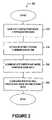
- FIG. 2is a flow chart illustrating the functions used to accomplish configuring a prospective-participant node as a participant node in a peer-to-peer network in accordance with one of the exemplary embodiments;
- FIG. 3is a display screen illustrating a user-dialog portion of a common application for configuring the prospective-participant node as a participant node in a peer-to-peer network in accordance with one of the exemplary embodiments;
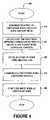
- FIG. 4is a flow diagram for illustrating exemplary functions for configuring two or more prospective-participant nodes to enable the prospective participant nodes to engage in peer-to-peer communication in accordance with one of the exemplary embodiments;
- FIG. 5is a flow chart 500 illustrating the functions used to accomplish interfacing with the common application in accordance with one of the exemplary embodiments.
- Various exemplary architecturesmay be used for deploying an exemplary embodiment of the present invention for configuring or “setting up” a prospective-participant node as a participant node in a peer-to-peer network. These various architectures enable the prospective-participant node to engage in a peer-to-peer communication in the peer-to-peer network with other participant nodes.
- the same or other assorted exemplary architecturesmay be used for carrying out another exemplary embodiment.
- the assorted architecturesprovide the structure to configure a plurality of prospective-participant nodes to enable each of the prospective-participant nodes to engage in peer-to-peer communication as a participant node in a peer-to-peer network.
- FIG. 1illustrates an exemplary architecture of a peer-to-peer network 100 in accordance with one of the various exemplary embodiments.
- the exemplary architecture of the peer-to-peer network 100which includes a prospective-participant node 110 and a participant node 160 (i.e. a node already configured as a participant node), may be used to set up of otherwise configure the prospective-participant node 110 as a participant node in a peer-to-peer network.
- Configuring the prospective-participant node 110enables the prospective-participant node to engage in a peer-to-peer communication in the peer-to-peer network with other participant nodes, such as participant node 160 .
- FIG. 1shows only one prospective-participant node, namely prospective-participant node 110
- the peer-to-peer network 100may include more than one prospective-participant node desiring to become a participant node in the peer-to-peer network.
- FIG. 1illustrates only one participant node, namely participant node 160
- the peer-to-peer network 100may have more than one participant node.
- the prospective-participant node 110after being configured as a participant node, may be able to beneficially communicate (e.g., exchange data and share resources) with not only the participant node 160 , but with the other participant nodes as well.
- the prospective-participant node 110 and the participant node 160may have substantially similar configurations because each node in a peer-to-peer network often has the same capabilities.
- the prospective-participant node 110 and a participant node 160each include a respective processor 112 , 162 , and a respective data-storage 114 , 164 , both of which may be managed by a respective operating system 116 , 166 .
- the processors 112 , 162may take various forms. For instance, each of the processors 112 and 162 may be a processing part of a computer and/or a standalone personal computer (PC) or multiple computers coupled together. Like the processors 112 , 162 , the data-storage 114 , 164 may take many forms. In one format, the data-storage 114 , 164 may be embodied as one or more digital-storage devices that are preferably integral to or integrated with the processor 112 , 162 . In this arrangement, the data-storage 114 , 164 and the processor 112 , 162 are communicatively coupled to each other, thereby allowing the data-storage 114 , 164 and the processor 112 , 162 to exchange data.
- the data-storage 114 , 164may be embodied as one or more stand-alone digital-storage devices, which are external, or otherwise separate from the processor 112 , 162 . These stand-alone devices, like the internal devices, may be communicatively coupled with the processor 114 , 164 using an external link, such as an Ethernet.
- the data-storage 114 , 164may comprise hard-drives, volatile and non-volatile memory, tape drives, optical media, and any other storage media capable of storing digital information.
- the processor 112 , 162 , and data-storage 114 , 164may provide a computing platform on which to store and run the operating system 116 , 166 and application layer programs (hereinafter referred to as “applications”).
- the computing platforms provided by the processors 112 , 162 and data-storage 114 , 164are managed by operating systems 116 , 166 , such as IBM AIX, UNIX, Linux, Microsoft Windows, and/or any other operating system.
- Each operating system 116 , 166may provide not only basic input and output functions, but also enhanced features and functions, such as data compression, to control the flow of data between the processor 112 , 162 and data-storage 114 , 164 .
- the operating system 116 , 166generally includes a file management system for storing and retrieving files on the data-storage 112 , 162 . Managing the interactions between the processors and the data storage, and controlling the processing of data and program instructions for the processors 112 , 162 and data-storage 114 , 164 , the operating system 116 , 166 thereby controls how applications operate.
- Both the prospective-participant node 110 and a participant node 160may also include a network interface, such as network-interface cards 118 , 168 , respectively.
- the network interface cards 118 , 168control the exchange of data between the nodes at the data-link-layer level.
- the data-link-layerprovides the link that allows the prospective-participant node 110 and the participant node 160 to connect to the physical network, and thus, to each other and/or other participant nodes.
- these network interface cards 118 , 168may have network-interface-card drivers (“network drivers”) that employ data-link layer protocols and services that allow the prospective-participant node 110 and a participant node 160 to connect to the physical network, and thus to each other and or other participant nodes.
- network driversnetwork-interface-card drivers
- the network driversmay use statically configured and/or dynamically configurable data-link-layer or physical-station addresses, such as MAC addresses. And these data-link-layer or physical-station addresses, i.e., prospective-node-link-layer-address 128 and participant-node-link-layer-address 178 , may be statically or dynamically configured into the network interface cards 118 and 168 , respectively.
- each of the network interface cards 118 , 168may have one or more statically configured or dynamically configurable node identifiers, namely prospective-participant-node identifier 130 and participant-node identifier 180 .
- These node identifiersmay reside in the data-link-layer level of the protocol stack so as to provide an additional indication of the network interfaces that are attached to the respective nodes.
- the prospective-participant-node identifier 130 and participant-node identifier 180may each be an ASCII representation of a name given to the attached node, such as “John's Computer,” and “Network Node 1 ,” respectively.
- the prospective-participant-node identifier 130 and participant-node identifier 180may take other forms as well, and the network interface cards 118 , 168 need not employ node identifiers.
- Interfacing the network driversare network interface drivers that reside in the network or IP layer.
- the network interface driversprovide an interface between the transport protocol, e.g., the TCP or UCP protocol, and the data link protocol.
- the network-interface driversprovide a protocol manager that accepts requests from the transport layer and activates the network-interface card. Examples of exemplary network interface drivers are Novell's ODI and Microsoft's NDIS.
- both the prospective-participant node 110 and a participant node 160may have respective network-configuration files, i.e., prospective-participant-config file 132 and participant-config file 182 .
- the participant-config file 182may have one or more configurable network-connection settings, referred to hereinafter as “participant-node-connection settings” 184 .
- These configurable participant-node-connection settings 184may be configured so as to define how to address the participant node 160 in the peer-to-peer network.
- the prospective-participant-config file 132may also contain one or more configurable network-connection settings, hereinafter referred to as “prospective-node-connection settings” 134 . Paralleling the participant-node-connection settings 184 , the prospective-node-connection settings 134 may be configured to define how to address the prospective-participant node 110 as a participant node in the peer-to-peer network.
- the respective network-configuration settings for both the prospective-participant node 110 and the participant node 160may include a unique network-layer address, such as an IP address, a subnet mask, a default gateway setting, and/or other network connection settings.
- a unique network-layer addresssuch as an IP address, a subnet mask, a default gateway setting, and/or other network connection settings.
- the prospective-participant node 110 and a participant node 160may also have respective user interfaces 120 , 170 , which assist users in interacting with the respective nodes, and in turn to other nodes using, of course, the protocol stack.
- Each of the user interfaces 120 , 170may have a display for displaying a combination of (i) indications, such as the node identifiers, (ii) other information ported to the application level as well as (iii) application level information.
- the user interfaces 120 , 170may include input and output (I/O) devices, such as (i) keyboards, (ii) mice, (iii) pointing and tap styluses, (iv) touch screens and (v) other I/O devices for receiving information from respective users. Other elements may compose the user interfaces 120 , 170 as well.
- exemplary configurations of the prospective-participant node 110 and a participant node 160may include devices having network interfaces cards for network connectivity such as desktop and laptop personal computers, personal digital assistants (PDAs), and/or wireless and cellular telephones.
- the prospective-participant node 110 and a participant node 160may take other forms as well.
- prospective-participant node 110 and a participant node 160each have other applications, such as common application 150 , stored on their respective data storage and executable by their respective processors.
- the common application 150includes logic, in hardware or software form, for carrying out one or more of the functions for (i) for configuring a prospective-participant node 110 as a participant node in a peer-to-peer network, and/or (ii) configuring two or more prospective-participant nodes to enable the prospective participant nodes to engage in peer-to-peer communication.
- FIG. 2is a flow chart 200 illustrating the functions used to accomplish configuring the prospective-participant node 110 as a participant node in a peer-to-peer network in accordance with an exemplary embodiment.
- the exemplary embodiment illustrated in FIG. 2is described with reference to FIG. 1 in which the common application 150 performs such functions. It is understood, however, that such description is for exemplary purposes only and that such functions may be carried out using different architecture.
- the functions for configuring the prospective-participant node 110 as a participant node in a peer-to-peer networkinclude (i) generating participant-node-configuration data 210 , (ii) establishing a point-to-point communication link 220 , (iii) communicating the participant-node-configuration data 230 , and (iv) configuring prospective-participant node as a participant node 240 .
- participant-node-configuration dataincludes one or more of the network-connection settings that define how to address the prospective-participant node 110 as a participant node in the peer-to-peer network.
- the network-connection settings included in the participant-node-configuration datawill be based on the network-configuration settings of the participant node 160 . (Note that the participant-node-connection settings 184 of the participant node 160 may have been previously configured.)
- the participant-node-connection settings 184may include a network identifier, a default or previously configured IP address setting, a default or previously configured subnet mask setting, a default or previously configured network gateway setting, and/or other connection settings.
- the IP address of the participant nodemust be a different IP address than the IP address of prospective-participant node 110 as well as any other participant node. To ensure that this occurs, the participant node 160 may generate one or more network or subnetwork connection settings.
- the IP address in the participant-node-configuration datamay have the same 8-bit host_id as the participant node 160 , but the participant-node-configuration data will have different 24-bit net_id.
- participant-node-configuration datamay have the same or substantially similar settings as the participant-node-connection settings 184 .
- the subnet mask in the participant-node-configuration datamay be the same as the subnet mask in participant-node-connection settings 184 .
- participant-node-configuration datacontains unique network connection settings when the network-connection settings for participant nodes need to be unique, and participant-node-configuration data contains common network connection settings where the network-connection settings for participant nodes to need to be the same.
- Another function of the common application 150 that may be carried out by the processors 112 , 162is the function is establishing a point-to-point communication link 220 between at least one of the other participant nodes and the prospective-participant node 110 .
- the common application 150includes discovery-process logic in which the prospective-participant node 110 establishes a data-link-layer connection with the participant node 160 , and/or another participant node.
- the common application 150provides an advertising function, which allows the participant node 160 or any other participant node to advertise the existence of the peer-to-peer network 100 so that the prospective-participant node 110 can detect its presence.
- the participant node 160(or other participant node) may use a network identifier.
- the network identifiermay be any identifier, arbitrarily selected or rigidly assigned, that threads each of the participant nodes to the peer-to-peer network.
- the network identifiermay be, for example, an arbitrary network name, such as “the DENJ Network” and/or, in IEEE 802.11 vernacular, an independent service set identifier (ISSID).
- the network identifiermay take various other forms as well.
- the participant node 160may broadcast, multicast or unicast the network identifier and other data-link-layer parameters, such as the participant-node-link-layer-address 128 , to the prospective-participant node 110 over a particular channel provisioned into both nodes by the common application 150 .
- the prospective-participant node 110may detect the network identifier and other data-link-layer parameters when listening on the provisioned channel.
- the participant node 160may broadcast, multicast or unicast the network identifier and/or other data-link-layer parameters to the prospective-participant node 110 over a particular channel provisioned into only the participant nodes.
- the common application 150may contain a routine that enables the prospective-participant node 110 to scan a plurality of channels in an attempt to detect the network identifier and other data-link-layer parameters.
- secure connection system mechanismsmay be in accord with one or more secure connection protocols, such as such as secure socket layer (SSL), security system (SSID), extensible authentication protocol (EAP) for wired networks, wired-equivalent privacy (WEP) for wireless peer-to-peer networks, Internet Protocol Security (IPSEC), Layer 2 Tunneling Protocol (L2TP), Transport Layer Security (TLS), and others.
- SSLsecure socket layer
- SSIDsecurity system
- EAPextensible authentication protocol
- WEPwired-equivalent privacy
- IPSECInternet Protocol Security
- L2TPLayer 2 Tunneling Protocol
- TLSTransport Layer Security
- the participant node 160may encrypt this information using one key of a shared-key encryption mechanism provided by the secure connection system mechanisms before advertising it to the prospective-participant node 110 .
- a shared-key encryption mechanismprovided by the secure connection system mechanisms
- the prospective-participant node 110may detect the advertised information. This prevents other, uninvited nodes from detecting the advertised network identifier and other data-link-layer parameters when the uninvited nodes happen to be listening on the particular channel on which the participant node 160 advertising such information.
- Using the secure connection system when establishing the point-to-point communication linkis particularly useful when the participant node 160 and the prospective-participant node 110 desire to carry on peer-to-peer communication at a location, e.g., a crowded seminar where other peer-to-peer communications are taking place as well. If only the participant node 160 and the prospective-participant node 110 are provisioned with the keys for encrypting/decrypting the network identifier, then other undesired prospective-participant nodes without the proper key will not detect the advertisement, and world at most likely consider the broadcast, multicast or unicast to be noise.
- the participant node 160may advertise the network identifier and other data-link-layer parameters to the prospective-participant node 110 unencrypted. After detecting the network identifier and other data-link-layer parameters, the prospective-participant node 110 , provisioned with keys of a shared-key security mechanism, sends an acknowledgement and one key of the shared-key encryption mechanism to the participant node 160 . The participant node 160 then uses this key in completing the negotiation of the data-link-layer connection with the prospective-participant node 110 .
- Yet another function of the common application 150 that may be carried out by the processors 112 , 162is the function of communicating participant-node-configuration data 230 . Included in this function is the process of establishing network access, which may be carried out over the point-to-point communication link.
- the process of establishing network accessmay be distributed between the participant node 160 and the prospective-participant node 110 .
- the prospective-participant node 110sends a request for network access over the point-to-point communication link.
- the request for network accessmay be sent over the data-link-layer connection. Included in this request is the prospective-participant-node identifier 130 with which the participant node 160 determines if any network services are available to the prospective-participant node 110 .
- the participant node 160may determine if any network services are available to the prospective-participant node 110 in various ways. For instance, participant node 160 , via its user interface 170 , may display to the user of participant node 160 an indication that contains the node identifier of the prospective participant node 110 . Such indication may be posed as a query, stating for example, “This is John's Computer, may I join your network?”
- the participant node 160(via the common application 150 ) is configured to receive user input, for instance, a “Yes/No” keystroke, to acknowledge that network services are or are not available to the prospective-participant node 110 .
- the participant node 160(via the common application 150 ) may be configured to accept all requests for network access, accept only request from specific computers, and/or accept requests based on some other decision mechanisms.
- the participant node 160may acknowledge that the network services are available by sending the participant-node-configuration data over the point-to-point communication link to the prospective-participant node 110 . If, on the other hand, no network services are available, the participant node 160 may send to the prospective-participant node 110 over the point-to-point communication link an acknowledgement, which contains an indication that denies network access.
- the prospective-participant node 110may receive over the point-to-point connection the acknowledgment with the participant-node-configuration data or the indication denying network access. After receiving the participant-node-configuration data, the prospective-participant node 110 may then configure itself as a participant node on the peer-to-peer network.
- the function of configuring the prospective-participant node 110 as a participant nodemay be carried by the common application 150 when executed by the processors 112 , 162 .
- the prospective-participant node 110may configure itself using the participant-node configuration data, in order to become a participant node.
- the prospective-participant node 110When configuring itself, the prospective-participant node 110 extracts the network-connection settings from the participant-node-configuration data. Using these network-configuration settings, the prospective participant node 110 then configures its configurable prospective-node-connection settings 134 . For example, assume that the network-configuration settings from the participant-node-configuration data contains an class C IP address xxx.xxx.xxx.xxx, and a subnet mask of 255.255.255.1. With this information, the prospective-participant node sets its IP address to the class C IP address xxx.xxx.xxx.xxx, and subnet mask value to 255.255.255.1.
- the prospective-participant node 110configures its configurable prospective-node-connection settings 134 with the settings from the participant-node-configuration data
- the prospective-participant node 110 network connection settingsare the settings for a participant node of the peer-to-peer network. This enables the prospective-participant node 110 (now a participant node in the peer-to-peer network) to engage in peer-to-peer communications with other participant nodes in the peer-to-peer network.
- FIG. 3is a display screen illustrating an exemplary user-dialog portion 300 of the common application 150 . While the screen is shown in a Microsoft Internet Explorer® window, user-dialog portion 300 may be sent to a different application display window or its own application display window. And while the functions carried out by the common application 150 may apply to both wired and wireless peer-to-peer networking, the following is described with reference to prospective-participant nodes for communicating in an IEEE 802.11 peer-to-peer or ad-hoc network. As noted above, however, the common application 150 is not limited to such prospective-participant nodes and may be used on participant nodes as well as prospective-participant nodes
- the user dialog portion 300 of the common application 150 on each prospective-participant nodesincludes a prospective-participant node role part 310 , a host node setting part 320 , a network-identifier-selection box 330 , a reset selection box 340 , and a submit selection box 350 .
- Included within the prospective-participant node role part 310are two labeled radio buttons. The first of the two labeled radio buttons is a guest node radio button 312 for selecting one of the prospective-participant nodes as a guest node. The second of two labeled radio buttons is a host node radio button 314 for selecting one or more of the prospective-participant nodes as a host node.
- the host node setting part 320includes two labeled check boxes for configuring two host node functions to enable the prospective-participant nodes to engage in peer-to-peer communications as participant nodes in the peer-to-peer network.
- the first of the two-labeled check boxesis an advertise-network-identifier box 322 .
- the second of the two check boxesis an enable-encryption box 324 .
- the network-identifier-selection box 330is drop down box for selecting the value of the network identifier, which in an IEEE 802.11, as noted above, may be a randomly generated or an arbitrarily selected SSID.
- the reset selection box 340is a virtual button that, when depressed, resets already selected and designated selections of the dialog portion of the common application 150 . Contrary to the function performed when depressing the reset selection box 340 , when depressing the virtual button designated as the submit selection box 350 , the processors of the prospective-participant nodes on which the common application 150 is executing performs functions for configuring two or more prospective-participant nodes to enable the prospective participant nodes to engage in peer-to-peer communication. It should be noted that each of the selectable parts of the user-dialog portion 300 may be programmed as “sticky” settings. In other words, the last setting used will be the default settings the next time used unless later changed by a user.
- a flow diagram 400is provided to illustrate exemplary functions for configuring two or more prospective-participant nodes to enable the prospective participant nodes to engage in peer-to-peer communication in accordance with an exemplary embodiment.
- the flow diagram 400 of FIG. 4is similar to the flow diagram 200 of FIG. 2 , except as described herein.
- the flow diagram 400is described with reference to the user-dialog portion 300 of the common application 150 illustrated in FIG. 3 and the exemplary architecture of a peer-to-peer network 100 illustrated in FIG. 1 .
- participant node 160 and its elementsare not yet configured as a participant node, but rather as a second prospective-participant node (hereinafter referred to as a “second-prospective-participant node” 160 ).
- Each of the elements of the second-prospective-participant node 160will be referred to as above with an appended prefix.
- the prospective-participant node 110will hereinafter be referred to as first-prospective-participant node 110 with its elements having a likewise added prefix.
- the flow diagram 400includes the functions of (i) designating one of the prospective-participant nodes as guest node and another of the prospective participant nodes as a host node as shown in block 410 ; (ii) using at least one network connection settings of the host node so as to generate participant-node-configuration data as shown in block 420 ; (iii) establishing a point-to-point communication link as shown in block 430 ; (iv) communicating the participant node configuration data as shown in block 440 ; and (v) configuring the guest node as a participant node as shown in block 450 .
- Designating one of the prospective-participant nodes as guest node and another of the prospective participant nodes as a host node as shown in block 410may be performed using at least two approaches.
- the first of these approachesrevolves around a user using the user-dialog portion 300 of the common application 150 .
- a user of each of the prospective-participant nodessimply selects the guest-node-radio button 312 or the host-node-radio button 314 , using their respective user interfaces, e.g., user interface 120 , keeping in mind that only one of the prospective-participant nodes may be the host node.
- a user of the first-prospective-participant node 110selects the guest-radio button 312 on the user-dialog portion 300 using its user interface 120 .
- a user of the second-prospective-participant node 160selects the host-radio button 314 on the user-dialog portion 300 using its user interface 170 .
- the user-dialog portion 300might not include a prospective-participant node role part 310 , but even if it does and the user designates the prospective-participant nodes as above, the host node and guest node designation may be designated without user interaction. Since the common application 150 allows any of the prospective-participant nodes to be configured as either a host node or a guest node, the prospective-participant nodes may engage in a discovery process using the node identifiers configured into the network interface cards.
- the first-prospective-participant node 110 and the second-prospective-participant node 160query their respective network cards for, at least, their (i) first-prospective-node-link-layer-address 128 and second-prospective-node-link-layer-address 178 , and (ii) first-prospective-node identifier 130 and second-prospective-node identifier 180 .
- the first-prospective-participant node 110 and the second-prospective-participant node 160may use a self-discovery utility called by the common application 150 . This self-discovery utility may be a standard operating system utility.
- the host node and guest nodemay be selected based on some predetermined criteria after the first-prospective-participant node 110 and the second-prospective-participant node 160 establish a point-to-point communication link, as will be described in more detail below.
- criteriamay include non-comparative and comparative thresholds.
- the comparative thresholdsmay be defined by the comparison of which of the nodes has a higher value data-link-layer address, which of the nodes was previously the host node, which of the nodes is currently a host in another peer-to-peer network, and other criteria.
- the common application 150uses the second-prospective-node-connection settings 184 of the now designated host node, hereinafter referred to as host node 160 , as service settings to generate participant-node-configuration data 420 .
- host node 160uses the second-prospective-node-connection settings 184 as service settings to generate participant-node-configuration data 420 .
- service settingsestablishes the host node 160 as participant node in the peer-to-peer network.
- the host node 160via a network-connection-discovery process determines its second-prospective-node-connection settings 184 .
- the common application 150 on the host node 160may call a standard operating system utility, such as IPCFG or WINIPCFG to determine its second-prospective-node-connection settings 184 .
- the common application 150 on host node 160may launch a dynamic-host-configuration-protocol routine to generate at least one set of network-configuration settings for the once prospective-participant node 110 , now guest node 110 .
- These network-configuration settingsmay include, for example a class C IP address xxx.xxx.xxx.xxx, and a subnet mask 255.255.255.1.
- the network-configuration settings for the guest node 110may have limited leases. These leases may be limited in duration; for example, the lease may only last for a period of time, such as 4 hours, or for so many bytes of data transferred.
- the host node 160may store these settings in a record in a database file on its data storage 164 .
- This database filemay be used to route information between participant nodes in the peer-to-peer network, since the network-connection setting for the all the participants in the peer-to-peer network will be contained in the database. Accordingly, this database file may be included in the participant-node-configuration data in lieu of the network-configuration settings for each of the guest node 110 .
- each of the records in the database filesmay be indexed by the data-link-layer addresses of the participant nodes.
- the database fileis not complete until the data-link-layer address of the guest node 110 is known by the host node.
- the host nodemay discover the data-link-layer address of the guest node 110 by establishing a point-to-point communication link with the guest node 110 as shown in block 430 .
- This functionmay be accomplished by establishing a point-to-point communication link between host node and the guest node as shown in block 430 .
- the user of the host node 160may place a check in the advertise-network-identifier box 322 , the enable-encryption box 324 and may choose which network-identifier from network-identifier-selection box 330 to use. As will be described in more detail below, each of these settings effect establishing the point-to-point communication link.
- This discovery-processincludes establishing a data-link-layer connection between the host node 160 and the guest node 110 .
- the guest node 110may establish data-link-layer connectivity with the host node 170 by detecting the presence of the ad hoc network and then initiating registration with the host node.
- Registering with the hostmay include merely “associating” with the host node 170 . Registering may also include employing secure connection services such as IEEE 802.11 Wired Equivalency Privacy (WEP), security system identifier (SSID), extensible authentication protocol (EAP) or other secure connection service.
- WEPWired Equivalency Privacy
- SSIDsecurity system identifier
- EAPextensible authentication protocol
- the process of associating host node 160 with the guest node 110may include one or more steps. Although described in more detail in the IEEE 802.11 protocol, an example of associating the host node 160 with the guest node 110 is illustrated with the following three steps. First, if advertise-network-identifier box 322 is checked, the host node 160 using an advertising function, broadcasts, multicasts or unicasts over one or more wireless channels on a wireless medium to the guest node 110 the network identifier, i.e., the SSID of the ad hoc network, defined in network-identifier-selection box 330 .
- the network identifieri.e., the SSID of the ad hoc network, defined in network-identifier-selection box 330 .
- the network identifier defined in network-identifier-selection box 330allows the host node to advertise the existence of the network so that the guest node can detect the presence of the peer-to-peer network.
- the network identifiermay be arbitrarily selected. As above, the network identifier threads each of the participant nodes to the peer-to-peer network.
- secure and/or “secret” peer-to-peer communicationmay be desired, and the establishing the point-to-point communication link may be preformed using secure connection system mechanisms.
- secure connection system mechanismsmay be in accord with one or more secure connection protocols, such as such as secure socket layer (SSL), security system identifier (SSID), extensible authentication protocol (EAP) for wired networks or wired-equivalent privacy (WEP).
- SSLsecure socket layer
- SSIDsecurity system identifier
- EAPextensible authentication protocol
- WEPwired-equivalent privacy
- the host node 160may encrypt this information before advertising it to the guest node using one key of a shared-key encryption mechanism provided by the secure connection system mechanisms. With the other key of the share-key encryption mechanism provisioned into the guest node 110 , only the guest node 110 may detect the advertised information. Alternatively, the host node 160 may advertise the network identifier and other data-link-layer parameters to the prospective-participant node unencrypted. After detecting the network identifier and other data-link-layer parameters, the host node 160 , provisioned with keys of a shared key security mechanism, sends an acknowledgement and one key of the shared key encryption mechanism to the guest node 110 . The guest node 110 then uses this key in completing the negotiation of the data-link-layer connection with the host node 160 .
- the guest node 110senses the wireless medium, and if the medium is free (i.e. no other node currently transmitting), then the guest node 110 transmits a request for synchronization information from the host node 160 . If, however, the wireless medium is busy, the guest node 110 delays transmission for a period of time before re-requesting the synchronization information. Once the synchronization information is received, the guest node 110 adjusts as needed, and then synchronizes with the host node 160 .
- the guest node 110 and host node 160exchange frames, or packet-data, containing their respective identities or addresses, namely the first-prospective-node-link-layer-address 128 and the second-prospective-node-link-layer-address 178 .
- the exchange of framesmay eventually result in the mutual verification of identity.
- the host node 160 and guest node 110are capable of transmitting and receiving participant-node-configuration data and other data-link-layer communications over the data-link-layer connection.
- the function of communicating participant-node-configuration data as shown in block 440is analogous to the communicating participant-node-configuration data function shown in block 230 of FIG. 2 .
- the process of establishing network accessmay be carried out over the point-to-point communication link and may be distributed between the guest node 110 and the host node 160 .
- the guest node 110sends a request for network access over the point-to-point communication link, which in an exemplary embodiment, is sent over the data-link-layer connection. Included in this request is the first-prospective-participant-node identifier 130 with which the host node 160 determines if any network services are available to the guest node 110 .
- the host node 160may determine if any network services are available to the guest node 110 in various ways. For instance, host node 160 , via its user interface 170 , may display to the user of host node 160 an indication that contains the node identifier of the guest node 110 . Such indication may be posed in a pop-up dialog window in which an indication carrying a query, stating for example, “This is John's Computer, may I join your network?”
- the user of the host node 160Using a keystroke, combination of keystrokes, mouse commands or other input, the user of the host node 160 acknowledges that network services are or are not available to the guest node 110 .
- the host node 160may accept all requests for network access, accept only request from specific computers, and/or accept requests based on some other decision mechanisms.
- the host node 160may acknowledge that the network services are available by sending the participant-node-configuration data over the point-to-point communication link to the guest node 110 . If, on the other hand, no network services are available, the host node 160 may send to the guest node 110 over the point-to-point communication link an acknowledgement that indicates denial of network access.
- the guest node 110While listening for a response to its request for network access, the guest node 110 may receive over the point-to-point connection the acknowledgment with the participant-node-configuration data or the indication denying network access. After receiving the participant-node-configuration data, the guest node may 110 then configure itself as a participant node on the peer-to-peer network as shown in block 450 .
- the function of configuring the guest node 110 as a participant node as shown in block 450may be carried by the common application 150 when executed by the processors 112 and 162 .
- the guest node 110may configure itself using the participant-node configuration data to become a participant node.
- the guest node 110When configuring itself, the guest node 110 extracts the network-configuration settings for the guest node from the participant-node-configuration data, which may include one or more records of network-connections settings. Using the network-configuration settings for the guest node, the guest node 110 then configures its configurable prospective-node-connection settings 134 .
- the guest node 110sets its IP address to the class C IP address xxx.xxx.xxx.xxx, and subnet mask value to 255.255.255.1.
- the network connection settings of the guest node 110are the settings for a participant node of the peer-to-peer network.
- the guest node 110With setting the guest node's network-connection settings and with the other records in the participant-node-configuration data, the guest node 110 (now a participant node in the peer-to-peer network) can engage in peer-to-peer communications with the host node 160 and any other participant nodes in the peer-to-peer network.
- FIG. 5is a flow chart 500 illustrating interfacing with the common application 150 in accordance with an exemplary embodiment.
- the common application 150performs the following steps, some of which are performed on the host node 160 and some of which are performed on the guest node 110 .
- the common application 150 on the host node 160determines if the network identifier on the host node 160 is selected. If the host node 160 determines that no network identifier is specified, it generates an error, which may require the user to select to select a network identifier or one will be arbitrarily selected.
- the common application 150determines if the network interface card of the host node 160 is set to peer-to-peer communication mode. If not, the common application 150 generates an error, and then requests the user to acknowledge that the mode of network interface card will be changed automatically to peer-to-peer communication mode.
- the common applicationdetermines if “IP Forwarding” on the host node 160 is enabled. If enabled, the common application will then generate and display on the user interface 170 of the host node 160 a warning message indicating that when forwarding the IP address of the host node 160 is enabled, the host node 160 is vulnerable to attacks on its security.
- the enable encryption box 324if the enable encryption box 324 is selected, the host node 160 dynamically generates a random WEP key.
- the common application 150 on the guest node 110will generate and display an error on the user interface 120 of the guest node 110 . This error may require the user to select to select a network identifier or one will be arbitrarily selected.
- the common application 150determines if the network interface card of the guest node 110 is set to peer-to-peer communication mode. If not, the common application 150 generates an error, and then requests the user to acknowledge that the mode of network interface card will be changed automatically to peer-to-peer communication mode.
- the common applicationdetermines if “IP Forwarding” is enabled on the guest node 110 . If enabled, the common application will then generate and display on the user interface 120 of the guest node 110 a warning message indicating that when forwarding the IP address of the guest node is enabled and that it is vulnerable to attacks on its security.
- the common application 150 on the guest node 110will determine if dynamic-host-configuration-protocol setting is enabled, and if not, the user will be prompted to have the static IP address and other network-connections settings saved to the data storage for later reset, if needed. After the static IP address and other network connection settings are saved, the user is prompted to change the dynamic-host-configuration-protocol setting to enabled. Alternatively, the common application 150 may save the IP address and other network-connections settings and change the dynamic-host-configuration-protocol setting automatically, i.e., without user intervention.
- the host node 160will initialize a dynamic-host-configuration-protocol routine or application using the network-connection settings of the host node 160 as service settings. Accordingly, the host node 160 will generate participant-node-configuration data.
- the common application 150 on the guest node 110will broadcast, multicast, or unicast a “join network request” using the network identifier so that host node 160 having the specified network identifier responds.
- the host node 160receives the “join network request” and a pop-up dialog window prompts the user of the host node 160 to determine if any network services are available to the guest node 110 .
- the common application 150 on the host node 160responds to the request with an “accept message” that contains the WEP key, if the enable encryption box 324 was selected.
- the guest node 110enables its security mechanisms using the WEP key.
- the common application 150 on the guest node 110using the WEP key, requests the participant-node-configuration data from the host node 160 .
- the host node 160sends to the guest node 110 the participant-node-configuration data. And at block 650 , the guest node 110 sets its configurable network connection settings using the network connection settings extracted from the participant-node-configuration data, thus making the guest node a participant in the peer-to-peer network.
Landscapes
- Engineering & Computer Science (AREA)
- Computer Networks & Wireless Communication (AREA)
- Signal Processing (AREA)
- Databases & Information Systems (AREA)
- Computer And Data Communications (AREA)
- Mobile Radio Communication Systems (AREA)
Abstract
Description
Claims (27)
Priority Applications (2)
| Application Number | Priority Date | Filing Date | Title |
|---|---|---|---|
| US10/287,960US7263070B1 (en) | 2002-11-05 | 2002-11-05 | Method and system for automating node configuration to facilitate peer-to-peer communication |
| US11/777,653US7990896B1 (en) | 2002-11-05 | 2007-07-13 | Method and system for automating node configuration to facilitate peer-to-peer communication |
Applications Claiming Priority (1)
| Application Number | Priority Date | Filing Date | Title |
|---|---|---|---|
| US10/287,960US7263070B1 (en) | 2002-11-05 | 2002-11-05 | Method and system for automating node configuration to facilitate peer-to-peer communication |
Related Child Applications (1)
| Application Number | Title | Priority Date | Filing Date |
|---|---|---|---|
| US11/777,653ContinuationUS7990896B1 (en) | 2002-11-05 | 2007-07-13 | Method and system for automating node configuration to facilitate peer-to-peer communication |
Publications (1)
| Publication Number | Publication Date |
|---|---|
| US7263070B1true US7263070B1 (en) | 2007-08-28 |
Family
ID=38433171
Family Applications (2)
| Application Number | Title | Priority Date | Filing Date |
|---|---|---|---|
| US10/287,960Expired - LifetimeUS7263070B1 (en) | 2002-11-05 | 2002-11-05 | Method and system for automating node configuration to facilitate peer-to-peer communication |
| US11/777,653Expired - LifetimeUS7990896B1 (en) | 2002-11-05 | 2007-07-13 | Method and system for automating node configuration to facilitate peer-to-peer communication |
Family Applications After (1)
| Application Number | Title | Priority Date | Filing Date |
|---|---|---|---|
| US11/777,653Expired - LifetimeUS7990896B1 (en) | 2002-11-05 | 2007-07-13 | Method and system for automating node configuration to facilitate peer-to-peer communication |
Country Status (1)
| Country | Link |
|---|---|
| US (2) | US7263070B1 (en) |
Cited By (66)
| Publication number | Priority date | Publication date | Assignee | Title |
|---|---|---|---|---|
| US20040034776A1 (en)* | 2002-08-14 | 2004-02-19 | Microsoft Corporation | Authenticating peer-to-peer connections |
| US20050086288A1 (en)* | 2003-10-20 | 2005-04-21 | Datta Glen V. | Peer-to-peer relay network |
| US20050125559A1 (en)* | 2003-12-02 | 2005-06-09 | Mutha Kailash K. | Employment of one or more identifiers of one or more communication devices to determine one or more internet protocol addresses |
| US20050153693A1 (en)* | 2004-01-13 | 2005-07-14 | Nokia Corporation | Client provisioning with flag parameters |
| US20050195757A1 (en)* | 2004-03-02 | 2005-09-08 | Kidder Kenneth B. | Wireless association approach and arrangement therefor |
| US20050195844A1 (en)* | 2004-02-09 | 2005-09-08 | Matsushita Electric Industrial Co., Ltd. | Communication control apparatus and network management system using the same |
| US20060072468A1 (en)* | 2004-09-30 | 2006-04-06 | Trollope David S | Method and apparatus for configuring a network node using multiple peer-to-peer layers |
| US20060095582A1 (en)* | 2004-10-29 | 2006-05-04 | Narasimhan Nitya | Device and method for transferring apportioned data in a mobile ad hoc network |
| US20060109790A1 (en)* | 2004-11-24 | 2006-05-25 | Microsoft Corporation | System and method for using a hop limited cast for internet egress point selection |
| US20060120370A1 (en)* | 2004-11-24 | 2006-06-08 | Microsoft Corporation | System and method for expanding the range of a mesh network |
| US20060153206A1 (en)* | 2004-11-29 | 2006-07-13 | Microsoft Corporation | System and method for dynamic egress routing through a single default gateway in a mesh network |
| US20060248525A1 (en)* | 2005-04-12 | 2006-11-02 | Hopkins Samuel P | System and method for detecting peer-to-peer network software |
| US20070233776A1 (en)* | 2005-11-14 | 2007-10-04 | Palm Stephen R | System for transmitting high throughput data between multiple devices |
| US20070286419A1 (en)* | 2006-06-07 | 2007-12-13 | Dmitri Varsanofiev | Efficient Video Delivery in Legacy 802.11 Infrastructure Enviroments |
| US20080126519A1 (en)* | 2003-09-30 | 2008-05-29 | Koninklijke Philips Electronics N.V. | Automatic Assignment Of A Network Id |
| US20080189351A1 (en)* | 2007-01-24 | 2008-08-07 | Shigeyuki Nemoto | Network system which performs peer-to-peer communication |
| US20080298376A1 (en)* | 2007-05-30 | 2008-12-04 | Sony Computer Entertainment Inc. | Network communication with path mtu size discovery |
| US20090061862A1 (en)* | 2007-08-30 | 2009-03-05 | Alberth Jr William P | Peer to peer service discovery sharing |
| US20090121845A1 (en)* | 2005-05-23 | 2009-05-14 | Wirecom Technologies | Communication system comprising a powerline communication network and at least one other communication network, corresponding node |
| US20090161643A1 (en)* | 2003-04-11 | 2009-06-25 | Sony Corporation | Radio communication system, radio communication apparatus and method, and program |
| US20090217346A1 (en)* | 2008-02-22 | 2009-08-27 | Manring Bradley A C | Dhcp centric network access management through network device access control lists |
| US20090222530A1 (en)* | 2005-08-23 | 2009-09-03 | Matsushita Electric Industrial Co., Ltd. | System and Method for Service Discovery in a Computer Network Using Dynamic Proxy and Data Dissemination |
| US20100161535A1 (en)* | 2008-12-18 | 2010-06-24 | Subhabrata Sen | Method and apparatus for inferring the presence of static internet protocol address allocations |
| US20100211785A1 (en)* | 2009-02-13 | 2010-08-19 | Samsung Electronics Co., Ltd. | System and method for automatic wireless connection between a portable terminal and a digital device |
| US20100287052A1 (en)* | 2009-05-06 | 2010-11-11 | Minter David D | Short-range commercial messaging and advertising system and mobile device for use therein |
| US20100325425A1 (en)* | 2009-06-18 | 2010-12-23 | Samsung Electronics Co., Ltd. | Method for automatic wlan connection between digital devices and digital device therefor |
| CN102065072A (en)* | 2010-09-21 | 2011-05-18 | 深圳市九洲电器有限公司 | Method and device for fast establishing PPPOE (Point-to-Point Protocol over Ethernet) link layer connection |
| US8005957B2 (en) | 2007-12-04 | 2011-08-23 | Sony Computer Entertainment Inc. | Network traffic prioritization |
| US8015300B2 (en) | 2008-03-05 | 2011-09-06 | Sony Computer Entertainment Inc. | Traversal of symmetric network address translator for multiple simultaneous connections |
| US8019082B1 (en)* | 2003-06-05 | 2011-09-13 | Mcafee, Inc. | Methods and systems for automated configuration of 802.1x clients |
| US8060626B2 (en) | 2008-09-22 | 2011-11-15 | Sony Computer Entertainment America Llc. | Method for host selection based on discovered NAT type |
| WO2011156725A3 (en)* | 2010-06-11 | 2012-02-02 | Research In Motion Limited | Method and apparatus for handling peers with dynamic ip connectivity status in peer-to-peer networks |
| CN102546323A (en)* | 2010-12-14 | 2012-07-04 | 中国科学院声学研究所 | Peer-to-peer network based on underwater sound and radio mixed channel |
| US8224985B2 (en) | 2005-10-04 | 2012-07-17 | Sony Computer Entertainment Inc. | Peer-to-peer communication traversing symmetric network address translators |
| US8326951B1 (en)* | 2004-06-05 | 2012-12-04 | Sonos, Inc. | Establishing a secure wireless network with minimum human intervention |
| US20130013757A1 (en)* | 2004-06-05 | 2013-01-10 | Millington Nicholas A J | Establishing a secure wireless network with minimum human intervention |
| EP2663022A1 (en)* | 2012-05-11 | 2013-11-13 | OTN Systems | A wired meshed network and a method for routing packets over a wired meshed network |
| EP2680176A4 (en)* | 2011-03-15 | 2014-10-22 | Omron Tateisi Electronics Co | DESIGN ASSISTING SYSTEM |
| EP2680175A4 (en)* | 2011-03-15 | 2014-11-19 | Omron Tateisi Electronics Co | DESIGN ASSISTING SYSTEM |
| US8910265B2 (en) | 2012-09-28 | 2014-12-09 | Sonos, Inc. | Assisted registration of audio sources |
| US9237384B2 (en) | 2013-02-14 | 2016-01-12 | Sonos, Inc. | Automatic configuration of household playback devices |
| US9241355B2 (en) | 2013-09-30 | 2016-01-19 | Sonos, Inc. | Media system access via cellular network |
| US9319409B2 (en) | 2013-02-14 | 2016-04-19 | Sonos, Inc. | Automatic configuration of household playback devices |
| US20160127881A1 (en)* | 2013-06-03 | 2016-05-05 | Lg Electronics Inc. | Discovery signal transmission method of terminal performing d2d communication and terminal using same |
| WO2017027552A1 (en)* | 2015-08-11 | 2017-02-16 | Catalina Marketing Corporation | Self-configuring media hub devices with passive monitoring of user devices and targeted media transmission |
| US9614915B2 (en)* | 2014-08-18 | 2017-04-04 | Google Inc. | Seamless peer to peer internet connectivity |
| US20170141962A1 (en)* | 2014-03-28 | 2017-05-18 | Hewlett Packard Enterprise Development Lp | Controlled node configuration |
| US9807206B2 (en)* | 2013-03-07 | 2017-10-31 | Apple Inc. | Aggregating physical network interfaces for peer-to-peer connections |
| US20170359406A1 (en)* | 2016-06-08 | 2017-12-14 | International Business Machines Corporation | Adaptive Query Targeting in a Dynamic Distributed Environment |
| US9933920B2 (en) | 2013-09-27 | 2018-04-03 | Sonos, Inc. | Multi-household support |
| US9977561B2 (en) | 2004-04-01 | 2018-05-22 | Sonos, Inc. | Systems, methods, apparatus, and articles of manufacture to provide guest access |
| US10031715B2 (en) | 2003-07-28 | 2018-07-24 | Sonos, Inc. | Method and apparatus for dynamic master device switching in a synchrony group |
| US10359987B2 (en) | 2003-07-28 | 2019-07-23 | Sonos, Inc. | Adjusting volume levels |
| USRE47628E1 (en) | 2005-04-12 | 2019-10-01 | Kroll Information Assurance, Llc | System for identifying the presence of peer-to-peer network software applications |
| USRE47843E1 (en)* | 2006-02-17 | 2020-02-04 | Canon Kabushiki Kaisha | Communication apparatus and communication layer role deciding method |
| US10613817B2 (en) | 2003-07-28 | 2020-04-07 | Sonos, Inc. | Method and apparatus for displaying a list of tracks scheduled for playback by a synchrony group |
| US11106424B2 (en) | 2003-07-28 | 2021-08-31 | Sonos, Inc. | Synchronizing operations among a plurality of independently clocked digital data processing devices |
| US11106425B2 (en) | 2003-07-28 | 2021-08-31 | Sonos, Inc. | Synchronizing operations among a plurality of independently clocked digital data processing devices |
| US11294618B2 (en) | 2003-07-28 | 2022-04-05 | Sonos, Inc. | Media player system |
| CN114423098A (en)* | 2020-10-10 | 2022-04-29 | 海能达通信股份有限公司 | Multi-base-station networking method, communication method of multi-base-station network and related device thereof |
| US20220255938A1 (en)* | 2021-02-07 | 2022-08-11 | Hangzhou Jindoutengyun Technologies Co., Ltd. | Method and system for processing network resource access requests, and computer device |
| CN115967555A (en)* | 2022-12-19 | 2023-04-14 | 南京科讯次元信息科技有限公司 | Cross-network-segment data link establishing and accessing method and system |
| US11650784B2 (en) | 2003-07-28 | 2023-05-16 | Sonos, Inc. | Adjusting volume levels |
| US11659385B2 (en)* | 2005-03-22 | 2023-05-23 | Interdigital Ce Patent Holdings, Sas | Method and system for peer-to-peer enforcement |
| US11995374B2 (en) | 2016-01-05 | 2024-05-28 | Sonos, Inc. | Multiple-device setup |
| US12155527B2 (en) | 2011-12-30 | 2024-11-26 | Sonos, Inc. | Playback devices and bonded zones |
Families Citing this family (7)
| Publication number | Priority date | Publication date | Assignee | Title |
|---|---|---|---|---|
| US8316088B2 (en)* | 2004-07-06 | 2012-11-20 | Nokia Corporation | Peer-to-peer engine for object sharing in communication devices |
| US8493946B2 (en)* | 2008-10-01 | 2013-07-23 | Digi International Inc. | Identifying a desired mesh network in a multiple network environment |
| US20110082939A1 (en)* | 2009-10-02 | 2011-04-07 | Michael Peter Montemurro | Methods and apparatus to proxy discovery and negotiations between network entities to establish peer-to-peer communications |
| US9949305B2 (en)* | 2009-10-02 | 2018-04-17 | Blackberry Limited | Methods and apparatus for peer-to-peer communications in a wireless local area network |
| US20140220946A1 (en)* | 2011-12-09 | 2014-08-07 | Samsung Electronics Co., Ltd. | Network participation method based on a user command, and groups and device adopting same |
| US9813423B2 (en) | 2013-02-26 | 2017-11-07 | International Business Machines Corporation | Trust-based computing resource authorization in a networked computing environment |
| CN115373729B (en)* | 2022-08-09 | 2023-04-25 | 北京多氪信息科技有限公司 | Method and device for processing auditing node |
Citations (4)
| Publication number | Priority date | Publication date | Assignee | Title |
|---|---|---|---|---|
| US20020073204A1 (en)* | 2000-12-07 | 2002-06-13 | Rabindranath Dutta | Method and system for exchange of node characteristics for DATA sharing in peer-to-peer DATA networks |
| US6826406B1 (en)* | 1998-01-29 | 2004-11-30 | Nokia Corporation | Method for reconfiguring a cellular radio network connection |
| US6892230B1 (en)* | 1999-06-11 | 2005-05-10 | Microsoft Corporation | Dynamic self-configuration for ad hoc peer networking using mark-up language formated description messages |
| US7065579B2 (en)* | 2001-01-22 | 2006-06-20 | Sun Microsystems, Inc. | System using peer discovery and peer membership protocols for accessing peer-to-peer platform resources on a network |
Family Cites Families (9)
| Publication number | Priority date | Publication date | Assignee | Title |
|---|---|---|---|---|
| US5987011A (en)* | 1996-08-30 | 1999-11-16 | Chai-Keong Toh | Routing method for Ad-Hoc mobile networks |
| US7327683B2 (en)* | 2000-03-16 | 2008-02-05 | Sri International | Method and apparatus for disseminating topology information and for discovering new neighboring nodes |
| US20020122410A1 (en)* | 2001-02-13 | 2002-09-05 | Cybiko Inc. | Method of wireless data exchange amongst devices of limited range |
| US7272636B2 (en)* | 2001-04-24 | 2007-09-18 | Sun Microsystems, Inc. | Peer group name server |
| US7353252B1 (en)* | 2001-05-16 | 2008-04-01 | Sigma Design | System for electronic file collaboration among multiple users using peer-to-peer network topology |
| US6845084B2 (en)* | 2001-12-28 | 2005-01-18 | Tsys Acquisition Corp. | Routing protocol selection for an ad hoc network |
| WO2003081848A1 (en)* | 2002-03-21 | 2003-10-02 | Cognio, Inc. | Ad-hoc control protocol governing use of an unlicensed or shared radio frequency band |
| US7657597B2 (en)* | 2002-09-26 | 2010-02-02 | Sun Microsystems, Inc. | Instant messaging using distributed indexes |
| US8037202B2 (en)* | 2002-10-31 | 2011-10-11 | Oracle America, Inc. | Presence detection using mobile agents in peer-to-peer networks |
- 2002
- 2002-11-05USUS10/287,960patent/US7263070B1/ennot_activeExpired - Lifetime
- 2007
- 2007-07-13USUS11/777,653patent/US7990896B1/ennot_activeExpired - Lifetime
Patent Citations (4)
| Publication number | Priority date | Publication date | Assignee | Title |
|---|---|---|---|---|
| US6826406B1 (en)* | 1998-01-29 | 2004-11-30 | Nokia Corporation | Method for reconfiguring a cellular radio network connection |
| US6892230B1 (en)* | 1999-06-11 | 2005-05-10 | Microsoft Corporation | Dynamic self-configuration for ad hoc peer networking using mark-up language formated description messages |
| US20020073204A1 (en)* | 2000-12-07 | 2002-06-13 | Rabindranath Dutta | Method and system for exchange of node characteristics for DATA sharing in peer-to-peer DATA networks |
| US7065579B2 (en)* | 2001-01-22 | 2006-06-20 | Sun Microsystems, Inc. | System using peer discovery and peer membership protocols for accessing peer-to-peer platform resources on a network |
Non-Patent Citations (6)
| Title |
|---|
| Installing TCP/IP, http://www/praticallynetworked.com/sharing/lansetup2.htm., pp. 1-7. Printed from Worldwide Web on Aug. 14, 2002. |
| Using DHCP, http://www/praticallynetworked.com//sharing/dhcp.htm, pp. 1-3. Printed from Worldwide Web on Aug. 14, 2002. |
| Why two Networks? http://www/praticallynetworked.com/sharing/twonets.htm, pp. 1-3. Printed from Worldwide Web on Aug. 14, 2002. |
| Wireless 101, http://www.compag.com/products/wireless/wlan/wireless101.html, pp. 1-2. Printed from Worldwide Web on Aug. 21, 2002. |
| Wireless Encryption Help, http://www/praticallynetworked.com//support/wireless<SUB>-</SUB>encrypt.htm, pp. 1-4. Printed from Worldwide Web on Aug. 14, 2002. |
| Wireless Lan Card settings for AdHoc communication, http://www/praticallynetworked.com/support/adhoc<SUB>-</SUB>setup.htm, pp. 1-3. Printed from Worldwide Web on Aug. 14, 2002. |
Cited By (184)
| Publication number | Priority date | Publication date | Assignee | Title |
|---|---|---|---|---|
| US7386878B2 (en)* | 2002-08-14 | 2008-06-10 | Microsoft Corporation | Authenticating peer-to-peer connections |
| US20040034776A1 (en)* | 2002-08-14 | 2004-02-19 | Microsoft Corporation | Authenticating peer-to-peer connections |
| US8340000B2 (en)* | 2003-04-11 | 2012-12-25 | Sony Corporation | Radio communication system, radio communication apparatus and method, and program |
| US20090161643A1 (en)* | 2003-04-11 | 2009-06-25 | Sony Corporation | Radio communication system, radio communication apparatus and method, and program |
| US8019082B1 (en)* | 2003-06-05 | 2011-09-13 | Mcafee, Inc. | Methods and systems for automated configuration of 802.1x clients |
| US11106425B2 (en) | 2003-07-28 | 2021-08-31 | Sonos, Inc. | Synchronizing operations among a plurality of independently clocked digital data processing devices |
| US11294618B2 (en) | 2003-07-28 | 2022-04-05 | Sonos, Inc. | Media player system |
| US11650784B2 (en) | 2003-07-28 | 2023-05-16 | Sonos, Inc. | Adjusting volume levels |
| US11635935B2 (en) | 2003-07-28 | 2023-04-25 | Sonos, Inc. | Adjusting volume levels |
| US11625221B2 (en) | 2003-07-28 | 2023-04-11 | Sonos, Inc | Synchronizing playback by media playback devices |
| US11556305B2 (en) | 2003-07-28 | 2023-01-17 | Sonos, Inc. | Synchronizing playback by media playback devices |
| US11550536B2 (en) | 2003-07-28 | 2023-01-10 | Sonos, Inc. | Adjusting volume levels |
| US11550539B2 (en) | 2003-07-28 | 2023-01-10 | Sonos, Inc. | Playback device |
| US10157035B2 (en) | 2003-07-28 | 2018-12-18 | Sonos, Inc. | Switching between a directly connected and a networked audio source |
| US10157034B2 (en) | 2003-07-28 | 2018-12-18 | Sonos, Inc. | Clock rate adjustment in a multi-zone system |
| US10175932B2 (en) | 2003-07-28 | 2019-01-08 | Sonos, Inc. | Obtaining content from direct source and remote source |
| US10175930B2 (en) | 2003-07-28 | 2019-01-08 | Sonos, Inc. | Method and apparatus for playback by a synchrony group |
| US10185540B2 (en) | 2003-07-28 | 2019-01-22 | Sonos, Inc. | Playback device |
| US10146498B2 (en) | 2003-07-28 | 2018-12-04 | Sonos, Inc. | Disengaging and engaging zone players |
| US11301207B1 (en) | 2003-07-28 | 2022-04-12 | Sonos, Inc. | Playback device |
| US10209953B2 (en) | 2003-07-28 | 2019-02-19 | Sonos, Inc. | Playback device |
| US11200025B2 (en) | 2003-07-28 | 2021-12-14 | Sonos, Inc. | Playback device |
| US11132170B2 (en) | 2003-07-28 | 2021-09-28 | Sonos, Inc. | Adjusting volume levels |
| US10140085B2 (en) | 2003-07-28 | 2018-11-27 | Sonos, Inc. | Playback device operating states |
| US10282164B2 (en) | 2003-07-28 | 2019-05-07 | Sonos, Inc. | Synchronizing operations among a plurality of independently clocked digital data processing devices |
| US11106424B2 (en) | 2003-07-28 | 2021-08-31 | Sonos, Inc. | Synchronizing operations among a plurality of independently clocked digital data processing devices |
| US10185541B2 (en) | 2003-07-28 | 2019-01-22 | Sonos, Inc. | Playback device |
| US10157033B2 (en) | 2003-07-28 | 2018-12-18 | Sonos, Inc. | Method and apparatus for switching between a directly connected and a networked audio source |
| US11080001B2 (en) | 2003-07-28 | 2021-08-03 | Sonos, Inc. | Concurrent transmission and playback of audio information |
| US10120638B2 (en) | 2003-07-28 | 2018-11-06 | Sonos, Inc. | Synchronizing operations among a plurality of independently clocked digital data processing devices |
| US10133536B2 (en) | 2003-07-28 | 2018-11-20 | Sonos, Inc. | Method and apparatus for adjusting volume in a synchrony group |
| US10963215B2 (en) | 2003-07-28 | 2021-03-30 | Sonos, Inc. | Media playback device and system |
| US10956119B2 (en) | 2003-07-28 | 2021-03-23 | Sonos, Inc. | Playback device |
| US10216473B2 (en) | 2003-07-28 | 2019-02-26 | Sonos, Inc. | Playback device synchrony group states |
| US10228902B2 (en) | 2003-07-28 | 2019-03-12 | Sonos, Inc. | Playback device |
| US10949163B2 (en) | 2003-07-28 | 2021-03-16 | Sonos, Inc. | Playback device |
| US10754613B2 (en) | 2003-07-28 | 2020-08-25 | Sonos, Inc. | Audio master selection |
| US10754612B2 (en) | 2003-07-28 | 2020-08-25 | Sonos, Inc. | Playback device volume control |
| US10747496B2 (en) | 2003-07-28 | 2020-08-18 | Sonos, Inc. | Playback device |
| US10613817B2 (en) | 2003-07-28 | 2020-04-07 | Sonos, Inc. | Method and apparatus for displaying a list of tracks scheduled for playback by a synchrony group |
| US10545723B2 (en) | 2003-07-28 | 2020-01-28 | Sonos, Inc. | Playback device |
| US10445054B2 (en) | 2003-07-28 | 2019-10-15 | Sonos, Inc. | Method and apparatus for switching between a directly connected and a networked audio source |
| US10387102B2 (en) | 2003-07-28 | 2019-08-20 | Sonos, Inc. | Playback device grouping |
| US10970034B2 (en) | 2003-07-28 | 2021-04-06 | Sonos, Inc. | Audio distributor selection |
| US10359987B2 (en) | 2003-07-28 | 2019-07-23 | Sonos, Inc. | Adjusting volume levels |
| US10324684B2 (en) | 2003-07-28 | 2019-06-18 | Sonos, Inc. | Playback device synchrony group states |
| US10303432B2 (en) | 2003-07-28 | 2019-05-28 | Sonos, Inc | Playback device |
| US10303431B2 (en) | 2003-07-28 | 2019-05-28 | Sonos, Inc. | Synchronizing operations among a plurality of independently clocked digital data processing devices |
| US10296283B2 (en) | 2003-07-28 | 2019-05-21 | Sonos, Inc. | Directing synchronous playback between zone players |
| US10289380B2 (en) | 2003-07-28 | 2019-05-14 | Sonos, Inc. | Playback device |
| US10031715B2 (en) | 2003-07-28 | 2018-07-24 | Sonos, Inc. | Method and apparatus for dynamic master device switching in a synchrony group |
| US20080126519A1 (en)* | 2003-09-30 | 2008-05-29 | Koninklijke Philips Electronics N.V. | Automatic Assignment Of A Network Id |
| US7792968B2 (en)* | 2003-10-20 | 2010-09-07 | Sony Computer Entertainment America Llc | Method of maintaining a peer-to-peer relay network |
| US20050086288A1 (en)* | 2003-10-20 | 2005-04-21 | Datta Glen V. | Peer-to-peer relay network |
| US7627678B2 (en)* | 2003-10-20 | 2009-12-01 | Sony Computer Entertainment America Inc. | Connecting a peer in a peer-to-peer relay network |
| US20080046555A1 (en)* | 2003-10-20 | 2008-02-21 | Datta Glen V | Peer-to-peer relay network |
| US20080046554A1 (en)* | 2003-10-20 | 2008-02-21 | Datta Glen V | Peer-to-peer relay network |
| US8396984B2 (en)* | 2003-10-20 | 2013-03-12 | Sony Computer Entertainment America Inc. | Peer-to-peer relay network with decentralized control |
| US20050125559A1 (en)* | 2003-12-02 | 2005-06-09 | Mutha Kailash K. | Employment of one or more identifiers of one or more communication devices to determine one or more internet protocol addresses |
| US20050153693A1 (en)* | 2004-01-13 | 2005-07-14 | Nokia Corporation | Client provisioning with flag parameters |
| US7809809B2 (en)* | 2004-01-13 | 2010-10-05 | Nokia Corporation | Client provisioning using application characteristics template with flag parameters |
| US7324463B2 (en)* | 2004-02-09 | 2008-01-29 | Matsushita Electric Industrial Co., Ltd. | Communication control apparatus and network management system using the same |
| US20050195844A1 (en)* | 2004-02-09 | 2005-09-08 | Matsushita Electric Industrial Co., Ltd. | Communication control apparatus and network management system using the same |
| US20050195757A1 (en)* | 2004-03-02 | 2005-09-08 | Kidder Kenneth B. | Wireless association approach and arrangement therefor |
| US11907610B2 (en) | 2004-04-01 | 2024-02-20 | Sonos, Inc. | Guess access to a media playback system |
| US11467799B2 (en) | 2004-04-01 | 2022-10-11 | Sonos, Inc. | Guest access to a media playback system |
| US9977561B2 (en) | 2004-04-01 | 2018-05-22 | Sonos, Inc. | Systems, methods, apparatus, and articles of manufacture to provide guest access |
| US10983750B2 (en) | 2004-04-01 | 2021-04-20 | Sonos, Inc. | Guest access to a media playback system |
| US10965545B2 (en) | 2004-06-05 | 2021-03-30 | Sonos, Inc. | Playback device connection |
| US9787550B2 (en) | 2004-06-05 | 2017-10-10 | Sonos, Inc. | Establishing a secure wireless network with a minimum human intervention |
| US12224898B2 (en) | 2004-06-05 | 2025-02-11 | Sonos, Inc. | Wireless device connection |
| US11909588B2 (en) | 2004-06-05 | 2024-02-20 | Sonos, Inc. | Wireless device connection |
| US9866447B2 (en) | 2004-06-05 | 2018-01-09 | Sonos, Inc. | Indicator on a network device |
| US11894975B2 (en) | 2004-06-05 | 2024-02-06 | Sonos, Inc. | Playback device connection |
| US8326951B1 (en)* | 2004-06-05 | 2012-12-04 | Sonos, Inc. | Establishing a secure wireless network with minimum human intervention |
| US20130013757A1 (en)* | 2004-06-05 | 2013-01-10 | Millington Nicholas A J | Establishing a secure wireless network with minimum human intervention |
| US8868698B2 (en)* | 2004-06-05 | 2014-10-21 | Sonos, Inc. | Establishing a secure wireless network with minimum human intervention |
| US10439896B2 (en) | 2004-06-05 | 2019-10-08 | Sonos, Inc. | Playback device connection |
| US10541883B2 (en) | 2004-06-05 | 2020-01-21 | Sonos, Inc. | Playback device connection |
| US9960969B2 (en) | 2004-06-05 | 2018-05-01 | Sonos, Inc. | Playback device connection |
| US9130770B2 (en) | 2004-06-05 | 2015-09-08 | Sonos, Inc. | Establishing a secure wireless network with a minimum human intervention |
| US9130771B2 (en) | 2004-06-05 | 2015-09-08 | Sonos, Inc. | Establishing a secure wireless network with minimum human intervention |
| US11456928B2 (en) | 2004-06-05 | 2022-09-27 | Sonos, Inc. | Playback device connection |
| US10097423B2 (en) | 2004-06-05 | 2018-10-09 | Sonos, Inc. | Establishing a secure wireless network with minimum human intervention |
| US11025509B2 (en) | 2004-06-05 | 2021-06-01 | Sonos, Inc. | Playback device connection |
| US10979310B2 (en) | 2004-06-05 | 2021-04-13 | Sonos, Inc. | Playback device connection |
| US7788347B2 (en)* | 2004-09-30 | 2010-08-31 | Alcatel-Lucent Usa Inc. | Method and apparatus for configuring a network node using multiple peer-to-peer layers |
| US20060072468A1 (en)* | 2004-09-30 | 2006-04-06 | Trollope David S | Method and apparatus for configuring a network node using multiple peer-to-peer layers |
| US20060095582A1 (en)* | 2004-10-29 | 2006-05-04 | Narasimhan Nitya | Device and method for transferring apportioned data in a mobile ad hoc network |
| US7643483B2 (en)* | 2004-11-24 | 2010-01-05 | Microsoft Corporation | System and method for using a hop limited cast for internet egress point selection |
| US20060120370A1 (en)* | 2004-11-24 | 2006-06-08 | Microsoft Corporation | System and method for expanding the range of a mesh network |
| US20060109790A1 (en)* | 2004-11-24 | 2006-05-25 | Microsoft Corporation | System and method for using a hop limited cast for internet egress point selection |
| US7715395B2 (en) | 2004-11-24 | 2010-05-11 | Microsoft Corporation | System and method for expanding the range of a mesh network |
| US20060153206A1 (en)* | 2004-11-29 | 2006-07-13 | Microsoft Corporation | System and method for dynamic egress routing through a single default gateway in a mesh network |
| US7649899B2 (en) | 2004-11-29 | 2010-01-19 | Microsoft Corporation | System and method for dynamic egress routing through a single default gateway in a mesh network |
| US11659385B2 (en)* | 2005-03-22 | 2023-05-23 | Interdigital Ce Patent Holdings, Sas | Method and system for peer-to-peer enforcement |
| US20060248525A1 (en)* | 2005-04-12 | 2006-11-02 | Hopkins Samuel P | System and method for detecting peer-to-peer network software |
| US9178940B2 (en)* | 2005-04-12 | 2015-11-03 | Tiversa Ip, Inc. | System and method for detecting peer-to-peer network software |
| USRE47628E1 (en) | 2005-04-12 | 2019-10-01 | Kroll Information Assurance, Llc | System for identifying the presence of peer-to-peer network software applications |
| US20090121845A1 (en)* | 2005-05-23 | 2009-05-14 | Wirecom Technologies | Communication system comprising a powerline communication network and at least one other communication network, corresponding node |
| US20090222530A1 (en)* | 2005-08-23 | 2009-09-03 | Matsushita Electric Industrial Co., Ltd. | System and Method for Service Discovery in a Computer Network Using Dynamic Proxy and Data Dissemination |
| US8224985B2 (en) | 2005-10-04 | 2012-07-17 | Sony Computer Entertainment Inc. | Peer-to-peer communication traversing symmetric network address translators |
| US20070233776A1 (en)* | 2005-11-14 | 2007-10-04 | Palm Stephen R | System for transmitting high throughput data between multiple devices |
| US8009642B2 (en)* | 2005-11-14 | 2011-08-30 | Broadcom Corporation | System for transmitting high throughput data between multiple devices |
| USRE47843E1 (en)* | 2006-02-17 | 2020-02-04 | Canon Kabushiki Kaisha | Communication apparatus and communication layer role deciding method |
| US20070286419A1 (en)* | 2006-06-07 | 2007-12-13 | Dmitri Varsanofiev | Efficient Video Delivery in Legacy 802.11 Infrastructure Enviroments |
| US20080189351A1 (en)* | 2007-01-24 | 2008-08-07 | Shigeyuki Nemoto | Network system which performs peer-to-peer communication |
| US20080298376A1 (en)* | 2007-05-30 | 2008-12-04 | Sony Computer Entertainment Inc. | Network communication with path mtu size discovery |
| US7995478B2 (en) | 2007-05-30 | 2011-08-09 | Sony Computer Entertainment Inc. | Network communication with path MTU size discovery |
| US20090061862A1 (en)* | 2007-08-30 | 2009-03-05 | Alberth Jr William P | Peer to peer service discovery sharing |
| US8171123B2 (en) | 2007-12-04 | 2012-05-01 | Sony Computer Entertainment Inc. | Network bandwidth detection and distribution |
| US8943206B2 (en) | 2007-12-04 | 2015-01-27 | Sony Computer Entertainment Inc. | Network bandwidth detection and distribution |
| US8005957B2 (en) | 2007-12-04 | 2011-08-23 | Sony Computer Entertainment Inc. | Network traffic prioritization |
| US20090217346A1 (en)* | 2008-02-22 | 2009-08-27 | Manring Bradley A C | Dhcp centric network access management through network device access control lists |
| US8930545B2 (en) | 2008-03-05 | 2015-01-06 | Sony Computer Entertainment Inc. | Traversal of symmetric network address translator for multiple simultaneous connections |
| US8015300B2 (en) | 2008-03-05 | 2011-09-06 | Sony Computer Entertainment Inc. | Traversal of symmetric network address translator for multiple simultaneous connections |
| US8060626B2 (en) | 2008-09-22 | 2011-11-15 | Sony Computer Entertainment America Llc. | Method for host selection based on discovered NAT type |
| US20100161535A1 (en)* | 2008-12-18 | 2010-06-24 | Subhabrata Sen | Method and apparatus for inferring the presence of static internet protocol address allocations |
| US7945667B2 (en)* | 2008-12-18 | 2011-05-17 | At&T Intellectual Property I, L.P. | Method and apparatus for inferring the presence of static internet protocol address allocations |
| US20100211785A1 (en)* | 2009-02-13 | 2010-08-19 | Samsung Electronics Co., Ltd. | System and method for automatic wireless connection between a portable terminal and a digital device |
| US9722979B2 (en)* | 2009-02-13 | 2017-08-01 | Samsung Electronics Co., Ltd | System and method for automatic wireless connection between a portable terminal and a digital device |
| US10505908B2 (en)* | 2009-02-13 | 2019-12-10 | Samsung Electronics Co., Ltd | System and method for automatic wireless connection between a portable terminal and a digital device |
| US20100287052A1 (en)* | 2009-05-06 | 2010-11-11 | Minter David D | Short-range commercial messaging and advertising system and mobile device for use therein |
| US20100325425A1 (en)* | 2009-06-18 | 2010-12-23 | Samsung Electronics Co., Ltd. | Method for automatic wlan connection between digital devices and digital device therefor |
| US8848915B2 (en)* | 2009-06-18 | 2014-09-30 | Samsung Electronics Co., Ltd | Method for automatic WLAN connection between digital devices and digital device therefor |
| WO2011156725A3 (en)* | 2010-06-11 | 2012-02-02 | Research In Motion Limited | Method and apparatus for handling peers with dynamic ip connectivity status in peer-to-peer networks |
| US9237060B2 (en) | 2010-06-11 | 2016-01-12 | Blackberry Limited | Method and apparatus for handling peers with dynamic IP connectivity status in peer-to-peer networks |
| CN102065072B (en)* | 2010-09-21 | 2013-12-25 | 深圳市九洲电器有限公司 | Method and device for fast establishing PPPOE (Point-to-Point Protocol over Ethernet) link layer connection |
| CN102065072A (en)* | 2010-09-21 | 2011-05-18 | 深圳市九洲电器有限公司 | Method and device for fast establishing PPPOE (Point-to-Point Protocol over Ethernet) link layer connection |
| CN102546323A (en)* | 2010-12-14 | 2012-07-04 | 中国科学院声学研究所 | Peer-to-peer network based on underwater sound and radio mixed channel |
| CN102546323B (en)* | 2010-12-14 | 2014-05-07 | 中国科学院声学研究所 | Realization method of peer-to-peer network based on underwater sound and radio mixed channel |
| EP2680176B1 (en) | 2011-03-15 | 2016-05-11 | Omron Corporation | Design assistance system |
| EP2680175B1 (en) | 2011-03-15 | 2016-02-24 | Omron Corporation | Design assistance system |
| EP2680176A4 (en)* | 2011-03-15 | 2014-10-22 | Omron Tateisi Electronics Co | DESIGN ASSISTING SYSTEM |
| EP2680175A4 (en)* | 2011-03-15 | 2014-11-19 | Omron Tateisi Electronics Co | DESIGN ASSISTING SYSTEM |
| US12155527B2 (en) | 2011-12-30 | 2024-11-26 | Sonos, Inc. | Playback devices and bonded zones |
| CN104380659B (en)* | 2012-05-11 | 2017-11-17 | Otn系统公司 | Wired mesh network and the method for the routing packets on wired mesh network |
| EP2663022A1 (en)* | 2012-05-11 | 2013-11-13 | OTN Systems | A wired meshed network and a method for routing packets over a wired meshed network |
| CN104380659A (en)* | 2012-05-11 | 2015-02-25 | Otn系统公司 | Wired meshed network and method for routing packets over wired meshed network |
| WO2013167648A1 (en)* | 2012-05-11 | 2013-11-14 | Otn Systems | A wired meshed network and a method for routing packets over a wired meshed network |
| US9876787B2 (en) | 2012-09-28 | 2018-01-23 | Sonos, Inc. | Streaming music using authentication information |
| US9432365B2 (en) | 2012-09-28 | 2016-08-30 | Sonos, Inc. | Streaming music using authentication information |
| US8910265B2 (en) | 2012-09-28 | 2014-12-09 | Sonos, Inc. | Assisted registration of audio sources |
| US9185103B2 (en) | 2012-09-28 | 2015-11-10 | Sonos, Inc. | Streaming music using authentication information |
| US10779024B2 (en) | 2013-02-14 | 2020-09-15 | Sonos, Inc. | Configuration of playback device audio settings |
| US9319409B2 (en) | 2013-02-14 | 2016-04-19 | Sonos, Inc. | Automatic configuration of household playback devices |
| US10271078B2 (en) | 2013-02-14 | 2019-04-23 | Sonos, Inc. | Configuration of playback device audio settings |
| US9686282B2 (en)* | 2013-02-14 | 2017-06-20 | Sonos, Inc. | Automatic configuration of household playback devices |
| US11979622B2 (en) | 2013-02-14 | 2024-05-07 | Sonos, Inc. | Configuration of playback device audio settings |
| US11178441B2 (en) | 2013-02-14 | 2021-11-16 | Sonos, Inc. | Configuration of playback device audio settings |
| US20160182513A1 (en)* | 2013-02-14 | 2016-06-23 | Sonos, Inc. | Automatic Configuration of Household Playback Devices |
| US9237384B2 (en) | 2013-02-14 | 2016-01-12 | Sonos, Inc. | Automatic configuration of household playback devices |
| US12348801B2 (en) | 2013-02-14 | 2025-07-01 | Sonos, Inc. | Configuration of playback device audio settings |
| US11539995B2 (en) | 2013-02-14 | 2022-12-27 | Sonos, Inc. | Configuration of playback device audio settings |
| US9807206B2 (en)* | 2013-03-07 | 2017-10-31 | Apple Inc. | Aggregating physical network interfaces for peer-to-peer connections |
| US20160127881A1 (en)* | 2013-06-03 | 2016-05-05 | Lg Electronics Inc. | Discovery signal transmission method of terminal performing d2d communication and terminal using same |
| US9736674B2 (en)* | 2013-06-03 | 2017-08-15 | Lg Electronics Inc. | Discovery signal transmission method of terminal performing D2D communication and terminal using same |
| US11829590B2 (en) | 2013-09-27 | 2023-11-28 | Sonos, Inc. | Multi-household support |
| US11494060B2 (en) | 2013-09-27 | 2022-11-08 | Sonos, Inc. | Multi-household support |
| US10969940B2 (en) | 2013-09-27 | 2021-04-06 | Sonos, Inc. | Multi-household support |
| US12135865B2 (en) | 2013-09-27 | 2024-11-05 | Sonos, Inc. | Multi-household support |
| US9933920B2 (en) | 2013-09-27 | 2018-04-03 | Sonos, Inc. | Multi-household support |
| US11129005B2 (en) | 2013-09-30 | 2021-09-21 | Sonos, Inc. | Media playback system control via cellular network |
| US12096326B2 (en) | 2013-09-30 | 2024-09-17 | Sonos, Inc. | Media playback system control via multiple networks |
| US10425789B2 (en) | 2013-09-30 | 2019-09-24 | Sonos, Inc. | Proximity-based media system disconnect |
| US9241355B2 (en) | 2013-09-30 | 2016-01-19 | Sonos, Inc. | Media system access via cellular network |
| US11722870B2 (en) | 2013-09-30 | 2023-08-08 | Sonos, Inc. | Media playback system control via multiple networks |
| US10826768B2 (en)* | 2014-03-28 | 2020-11-03 | Hewlett Packard Enterprise Development Lp | Controlled node configuration |
| US20170141962A1 (en)* | 2014-03-28 | 2017-05-18 | Hewlett Packard Enterprise Development Lp | Controlled node configuration |
| US9614915B2 (en)* | 2014-08-18 | 2017-04-04 | Google Inc. | Seamless peer to peer internet connectivity |
| US10977634B2 (en) | 2015-08-11 | 2021-04-13 | Catalina Marketing Corporation | Media hub devices with passive monitoring of user devices and targeted media transmission through in-channel transmission or shifted channel transmission |
| US11875326B2 (en) | 2015-08-11 | 2024-01-16 | Catalina Marketing Corporation | Media hub devices with passive monitoring of user devices and targeted media transmission through in-channel transmission or shifted channel transmission |
| WO2017027552A1 (en)* | 2015-08-11 | 2017-02-16 | Catalina Marketing Corporation | Self-configuring media hub devices with passive monitoring of user devices and targeted media transmission |
| JP2021152913A (en)* | 2015-08-11 | 2021-09-30 | カタリナ マーケティング コーポレーション | System and method for self-configuring networked medium hub device |
| US10643195B2 (en) | 2015-08-11 | 2020-05-05 | Catalina Marketing Corporation | Self-configuring networked media hub devices with automated configuration and failover recovery of peers |
| JP2018526904A (en)* | 2015-08-11 | 2018-09-13 | カタリナ マーケティング コーポレーション | Self-configuration of media hub devices with passive monitoring of user devices and target media transmission |
| US11995374B2 (en) | 2016-01-05 | 2024-05-28 | Sonos, Inc. | Multiple-device setup |
| US20170359406A1 (en)* | 2016-06-08 | 2017-12-14 | International Business Machines Corporation | Adaptive Query Targeting in a Dynamic Distributed Environment |
| US10334025B2 (en)* | 2016-06-08 | 2019-06-25 | International Business Machines Corporation | Adaptive query targeting in a dynamic distributed environment |
| CN114423098A (en)* | 2020-10-10 | 2022-04-29 | 海能达通信股份有限公司 | Multi-base-station networking method, communication method of multi-base-station network and related device thereof |
| CN114423098B (en)* | 2020-10-10 | 2024-02-06 | 海能达通信股份有限公司 | Multi-base station networking method, multi-base station network communication method and related devices thereof |
| US11979405B2 (en)* | 2021-02-07 | 2024-05-07 | Hangzhou Jindoutengyun Technologies Co., Ltd. | Method and system for processing network resource access requests, and computer device |
| US20220255938A1 (en)* | 2021-02-07 | 2022-08-11 | Hangzhou Jindoutengyun Technologies Co., Ltd. | Method and system for processing network resource access requests, and computer device |
| CN115967555A (en)* | 2022-12-19 | 2023-04-14 | 南京科讯次元信息科技有限公司 | Cross-network-segment data link establishing and accessing method and system |
Also Published As
| Publication number | Publication date |
|---|---|
| US7990896B1 (en) | 2011-08-02 |
Similar Documents
| Publication | Publication Date | Title |
|---|---|---|
| US7263070B1 (en) | Method and system for automating node configuration to facilitate peer-to-peer communication | |
| US10505908B2 (en) | System and method for automatic wireless connection between a portable terminal and a digital device | |
| US10135827B2 (en) | Secure access to remote resources over a network | |
| US10291956B2 (en) | Methods and systems for enabling communications between devices | |
| US8848915B2 (en) | Method for automatic WLAN connection between digital devices and digital device therefor | |
| US7342906B1 (en) | Distributed wireless network security system | |
| JP4555235B2 (en) | Network device, method of using wireless network, and method of wireless network security | |
| US8605582B2 (en) | IP network system and its access control method, IP address distributing device, and IP address distributing method | |
| US7752653B1 (en) | Method and apparatus for registering auto-configured network addresses based on connection authentication | |
| US7266090B2 (en) | Address autoconfiguration method for home network | |
| US20050114490A1 (en) | Distributed virtual network access system and method | |
| EP2819363B1 (en) | Method, device and system for providing network traversing service | |
| US20030140142A1 (en) | Initiating connections through firewalls and network address translators | |
| CN103580980A (en) | Automatic searching and automatic configuration method and device of VN | |
| CN113542389A (en) | Private cloud routing server connection mechanism for private communication architecture | |
| US20100058232A1 (en) | Virtual network join protocol | |
| JP3858884B2 (en) | Network access gateway, network access gateway control method and program | |
| JP2009512368A (en) | Communication system and communication method | |
| US7546458B1 (en) | Method for organizing virtual networks while optimizing security | |
| JP2004312482A (en) | Network system, network identifier setting method, access authentication information management device, program thereof, network connection point, network identifier setting program, and recording medium | |
| JP2005038099A (en) | Information device and program for building wireless network | |
| US20060193330A1 (en) | Communication apparatus, router apparatus, communication method and computer program product | |
| US12063201B1 (en) | Enabling partial access to a local area network via a meshnet device | |
| JP2005079921A (en) | COMMUNICATION DEVICE, ADDRESS GENERATION METHOD, PROGRAM, AND STORAGE MEDIUM | |
| US20250240186A1 (en) | Community identifier of a group of client devices |
Legal Events
| Date | Code | Title | Description |
|---|---|---|---|
| AS | Assignment | Owner name:SPRINT SPECTRUM L.P., KANSAS Free format text:ASSIGNMENT OF ASSIGNORS INTEREST;ASSIGNORS:DELKER, JASON;EVERSON, JOHN;NORRIS, JIM;AND OTHERS;REEL/FRAME:013472/0555 Effective date:20021101 | |
| STCF | Information on status: patent grant | Free format text:PATENTED CASE | |
| FPAY | Fee payment | Year of fee payment:4 | |
| FPAY | Fee payment | Year of fee payment:8 | |
| AS | Assignment | Owner name:DEUTSCHE BANK TRUST COMPANY AMERICAS, NEW YORK Free format text:GRANT OF FIRST PRIORITY AND JUNIOR PRIORITY SECURITY INTEREST IN PATENT RIGHTS;ASSIGNOR:SPRINT SPECTRUM L.P.;REEL/FRAME:041937/0632 Effective date:20170203 | |
| MAFP | Maintenance fee payment | Free format text:PAYMENT OF MAINTENANCE FEE, 12TH YEAR, LARGE ENTITY (ORIGINAL EVENT CODE: M1553); ENTITY STATUS OF PATENT OWNER: LARGE ENTITY Year of fee payment:12 | |
| AS | Assignment | Owner name:DEUTSCHE BANK TRUST COMPANY AMERICAS, NEW YORK Free format text:SECURITY AGREEMENT;ASSIGNORS:T-MOBILE USA, INC.;ISBV LLC;T-MOBILE CENTRAL LLC;AND OTHERS;REEL/FRAME:053182/0001 Effective date:20200401 | |
| AS | Assignment | Owner name:SPRINT SPECTRUM L.P., KANSAS Free format text:TERMINATION AND RELEASE OF FIRST PRIORITY AND JUNIOR PRIORITY SECURITY INTEREST IN PATENT RIGHTS;ASSIGNOR:DEUTSCHE BANK TRUST COMPANY AMERICAS;REEL/FRAME:052313/0299 Effective date:20200401 | |
| AS | Assignment | Owner name:SPRINT SPECTRUM LLC, WASHINGTON Free format text:CHANGE OF NAME;ASSIGNOR:SPRINT SPECTRUM L.P.;REEL/FRAME:059044/0022 Effective date:20210325 | |
| AS | Assignment | Owner name:IBSV LLC, WASHINGTON Free format text:RELEASE BY SECURED PARTY;ASSIGNOR:DEUTSCHE BANK TRUST COMPANY AMERICAS;REEL/FRAME:062595/0001 Effective date:20220822 Owner name:SPRINT SPECTRUM LLC, KANSAS Free format text:RELEASE BY SECURED PARTY;ASSIGNOR:DEUTSCHE BANK TRUST COMPANY AMERICAS;REEL/FRAME:062595/0001 Effective date:20220822 Owner name:SPRINT INTERNATIONAL INCORPORATED, KANSAS Free format text:RELEASE BY SECURED PARTY;ASSIGNOR:DEUTSCHE BANK TRUST COMPANY AMERICAS;REEL/FRAME:062595/0001 Effective date:20220822 Owner name:SPRINT COMMUNICATIONS COMPANY L.P., KANSAS Free format text:RELEASE BY SECURED PARTY;ASSIGNOR:DEUTSCHE BANK TRUST COMPANY AMERICAS;REEL/FRAME:062595/0001 Effective date:20220822 Owner name:SPRINTCOM LLC, KANSAS Free format text:RELEASE BY SECURED PARTY;ASSIGNOR:DEUTSCHE BANK TRUST COMPANY AMERICAS;REEL/FRAME:062595/0001 Effective date:20220822 Owner name:CLEARWIRE IP HOLDINGS LLC, KANSAS Free format text:RELEASE BY SECURED PARTY;ASSIGNOR:DEUTSCHE BANK TRUST COMPANY AMERICAS;REEL/FRAME:062595/0001 Effective date:20220822 Owner name:CLEARWIRE COMMUNICATIONS LLC, KANSAS Free format text:RELEASE BY SECURED PARTY;ASSIGNOR:DEUTSCHE BANK TRUST COMPANY AMERICAS;REEL/FRAME:062595/0001 Effective date:20220822 Owner name:BOOST WORLDWIDE, LLC, KANSAS Free format text:RELEASE BY SECURED PARTY;ASSIGNOR:DEUTSCHE BANK TRUST COMPANY AMERICAS;REEL/FRAME:062595/0001 Effective date:20220822 Owner name:ASSURANCE WIRELESS USA, L.P., KANSAS Free format text:RELEASE BY SECURED PARTY;ASSIGNOR:DEUTSCHE BANK TRUST COMPANY AMERICAS;REEL/FRAME:062595/0001 Effective date:20220822 Owner name:T-MOBILE USA, INC., WASHINGTON Free format text:RELEASE BY SECURED PARTY;ASSIGNOR:DEUTSCHE BANK TRUST COMPANY AMERICAS;REEL/FRAME:062595/0001 Effective date:20220822 Owner name:T-MOBILE CENTRAL LLC, WASHINGTON Free format text:RELEASE BY SECURED PARTY;ASSIGNOR:DEUTSCHE BANK TRUST COMPANY AMERICAS;REEL/FRAME:062595/0001 Effective date:20220822 Owner name:PUSHSPRING, LLC, WASHINGTON Free format text:RELEASE BY SECURED PARTY;ASSIGNOR:DEUTSCHE BANK TRUST COMPANY AMERICAS;REEL/FRAME:062595/0001 Effective date:20220822 Owner name:LAYER3 TV, LLC, WASHINGTON Free format text:RELEASE BY SECURED PARTY;ASSIGNOR:DEUTSCHE BANK TRUST COMPANY AMERICAS;REEL/FRAME:062595/0001 Effective date:20220822 |