US7261705B2 - Implantable dialysis access port - Google Patents
Implantable dialysis access portDownload PDFInfo
- Publication number
- US7261705B2 US7261705B2US10/682,222US68222203AUS7261705B2US 7261705 B2US7261705 B2US 7261705B2US 68222203 AUS68222203 AUS 68222203AUS 7261705 B2US7261705 B2US 7261705B2
- Authority
- US
- United States
- Prior art keywords
- port
- graft
- channel
- arterial
- casing
- Prior art date
- Legal status (The legal status is an assumption and is not a legal conclusion. Google has not performed a legal analysis and makes no representation as to the accuracy of the status listed.)
- Expired - Fee Related, expires
Links
- 238000000502dialysisMethods0.000titleclaimsdescription76
- 238000007789sealingMethods0.000claimsabstractdescription46
- 239000008280bloodSubstances0.000claimsdescription71
- 210000004369bloodAnatomy0.000claimsdescription71
- 210000001367arteryAnatomy0.000claimsdescription40
- 239000012530fluidSubstances0.000claimsdescription18
- 238000004891communicationMethods0.000claimsdescription10
- 241000124008MammaliaSpecies0.000claimsdescription5
- 230000006378damageEffects0.000claimsdescription5
- 229920001343polytetrafluoroethylenePolymers0.000claimsdescription3
- 239000004809TeflonSubstances0.000claimsdescription2
- 229920006362Teflon®Polymers0.000claimsdescription2
- 229920000728polyesterPolymers0.000claimsdescription2
- 238000000034methodMethods0.000abstractdescription40
- 210000003462veinAnatomy0.000description32
- 238000001631haemodialysisMethods0.000description13
- 230000000322hemodialysisEffects0.000description13
- 210000004379membraneAnatomy0.000description9
- 239000012528membraneSubstances0.000description9
- 206010016717FistulaDiseases0.000description8
- 230000003890fistulaEffects0.000description8
- 230000003872anastomosisEffects0.000description7
- 238000002513implantationMethods0.000description7
- HTTJABKRGRZYRN-UHFFFAOYSA-NHeparinChemical compoundOC1C(NC(=O)C)C(O)OC(COS(O)(=O)=O)C1OC1C(OS(O)(=O)=O)C(O)C(OC2C(C(OS(O)(=O)=O)C(OC3C(C(O)C(O)C(O3)C(O)=O)OS(O)(=O)=O)C(CO)O2)NS(O)(=O)=O)C(C(O)=O)O1HTTJABKRGRZYRN-UHFFFAOYSA-N0.000description6
- 229960002897heparinDrugs0.000description6
- 229920000669heparinPolymers0.000description6
- 206010053567CoagulopathiesDiseases0.000description5
- 229940127090anticoagulant agentDrugs0.000description5
- 239000003146anticoagulant agentSubstances0.000description5
- 230000035602clottingEffects0.000description5
- 239000000463materialSubstances0.000description5
- 239000000243solutionSubstances0.000description5
- 239000000853adhesiveSubstances0.000description4
- 230000001070adhesive effectEffects0.000description4
- 230000006872improvementEffects0.000description4
- 210000003734kidneyAnatomy0.000description4
- 229920001296polysiloxanePolymers0.000description4
- 230000008569processEffects0.000description4
- 230000008901benefitEffects0.000description3
- 210000001124body fluidAnatomy0.000description3
- 239000003053toxinSubstances0.000description3
- 231100000765toxinToxicity0.000description3
- 108700012359toxinsProteins0.000description3
- 239000002699waste materialSubstances0.000description3
- FAPWRFPIFSIZLT-UHFFFAOYSA-MSodium chlorideChemical compound[Na+].[Cl-]FAPWRFPIFSIZLT-UHFFFAOYSA-M0.000description2
- 210000001015abdomenAnatomy0.000description2
- 230000017531blood circulationEffects0.000description2
- 230000006835compressionEffects0.000description2
- 238000007906compressionMethods0.000description2
- 238000001914filtrationMethods0.000description2
- 230000003907kidney functionEffects0.000description2
- 230000036407painEffects0.000description2
- 239000004033plasticSubstances0.000description2
- 239000003566sealing materialSubstances0.000description2
- 229910001220stainless steelInorganic materials0.000description2
- 239000010935stainless steelSubstances0.000description2
- 230000002792vascularEffects0.000description2
- 206010002091AnaesthesiaDiseases0.000description1
- 241001465754MetazoaSpecies0.000description1
- RTAQQCXQSZGOHL-UHFFFAOYSA-NTitaniumChemical compound[Ti]RTAQQCXQSZGOHL-UHFFFAOYSA-N0.000description1
- 230000003187abdominal effectEffects0.000description1
- 230000037005anaesthesiaEffects0.000description1
- 239000000560biocompatible materialSubstances0.000description1
- 239000003364biologic glueSubstances0.000description1
- 230000000747cardiac effectEffects0.000description1
- 210000003109clavicleAnatomy0.000description1
- 238000007796conventional methodMethods0.000description1
- 230000003247decreasing effectEffects0.000description1
- 239000007789gasSubstances0.000description1
- 206010020718hyperplasiaDiseases0.000description1
- 238000001802infusionMethods0.000description1
- 230000000977initiatory effectEffects0.000description1
- 238000002347injectionMethods0.000description1
- 239000007924injectionSubstances0.000description1
- 238000003780insertionMethods0.000description1
- 230000037431insertionEffects0.000description1
- 238000009434installationMethods0.000description1
- 208000028867ischemiaDiseases0.000description1
- 230000002045lasting effectEffects0.000description1
- 238000002690local anesthesiaMethods0.000description1
- 239000003589local anesthetic agentSubstances0.000description1
- 238000004519manufacturing processMethods0.000description1
- 229910052751metalInorganic materials0.000description1
- 239000002184metalSubstances0.000description1
- 239000000203mixtureSubstances0.000description1
- 238000012986modificationMethods0.000description1
- 230000004048modificationEffects0.000description1
- 238000012544monitoring processMethods0.000description1
- 210000000056organAnatomy0.000description1
- 230000008520organizationEffects0.000description1
- 230000035515penetrationEffects0.000description1
- 230000002093peripheral effectEffects0.000description1
- 210000003200peritoneal cavityAnatomy0.000description1
- 231100000614poisonToxicity0.000description1
- 238000005086pumpingMethods0.000description1
- 238000004064recyclingMethods0.000description1
- 230000000717retained effectEffects0.000description1
- 238000010079rubber tappingMethods0.000description1
- 210000003752saphenous veinAnatomy0.000description1
- 238000001356surgical procedureMethods0.000description1
- 208000011580syndromic diseaseDiseases0.000description1
- 230000001225therapeutic effectEffects0.000description1
- 210000001519tissueAnatomy0.000description1
- 230000008467tissue growthEffects0.000description1
- 239000010936titaniumSubstances0.000description1
- 229910052719titaniumInorganic materials0.000description1
- 239000003440toxic substanceSubstances0.000description1
- 239000010891toxic wasteSubstances0.000description1
- 210000002620vena cava superiorAnatomy0.000description1
Images


Classifications
- A—HUMAN NECESSITIES
- A61—MEDICAL OR VETERINARY SCIENCE; HYGIENE
- A61M—DEVICES FOR INTRODUCING MEDIA INTO, OR ONTO, THE BODY; DEVICES FOR TRANSDUCING BODY MEDIA OR FOR TAKING MEDIA FROM THE BODY; DEVICES FOR PRODUCING OR ENDING SLEEP OR STUPOR
- A61M1/00—Suction or pumping devices for medical purposes; Devices for carrying-off, for treatment of, or for carrying-over, body-liquids; Drainage systems
- A61M1/36—Other treatment of blood in a by-pass of the natural circulatory system, e.g. temperature adaptation, irradiation ; Extra-corporeal blood circuits
- A61M1/3621—Extra-corporeal blood circuits
- A61M1/3653—Interfaces between patient blood circulation and extra-corporal blood circuit
- A61M1/3655—Arterio-venous shunts or fistulae
- A—HUMAN NECESSITIES
- A61—MEDICAL OR VETERINARY SCIENCE; HYGIENE
- A61M—DEVICES FOR INTRODUCING MEDIA INTO, OR ONTO, THE BODY; DEVICES FOR TRANSDUCING BODY MEDIA OR FOR TAKING MEDIA FROM THE BODY; DEVICES FOR PRODUCING OR ENDING SLEEP OR STUPOR
- A61M1/00—Suction or pumping devices for medical purposes; Devices for carrying-off, for treatment of, or for carrying-over, body-liquids; Drainage systems
- A61M1/36—Other treatment of blood in a by-pass of the natural circulatory system, e.g. temperature adaptation, irradiation ; Extra-corporeal blood circuits
- A61M1/3621—Extra-corporeal blood circuits
- A61M1/3653—Interfaces between patient blood circulation and extra-corporal blood circuit
- A61M1/3659—Cannulae pertaining to extracorporeal circulation
- A61M1/3661—Cannulae pertaining to extracorporeal circulation for haemodialysis
- A—HUMAN NECESSITIES
- A61—MEDICAL OR VETERINARY SCIENCE; HYGIENE
- A61M—DEVICES FOR INTRODUCING MEDIA INTO, OR ONTO, THE BODY; DEVICES FOR TRANSDUCING BODY MEDIA OR FOR TAKING MEDIA FROM THE BODY; DEVICES FOR PRODUCING OR ENDING SLEEP OR STUPOR
- A61M39/00—Tubes, tube connectors, tube couplings, valves, access sites or the like, specially adapted for medical use
- A61M39/02—Access sites
- A61M39/0208—Subcutaneous access sites for injecting or removing fluids
- A—HUMAN NECESSITIES
- A61—MEDICAL OR VETERINARY SCIENCE; HYGIENE
- A61M—DEVICES FOR INTRODUCING MEDIA INTO, OR ONTO, THE BODY; DEVICES FOR TRANSDUCING BODY MEDIA OR FOR TAKING MEDIA FROM THE BODY; DEVICES FOR PRODUCING OR ENDING SLEEP OR STUPOR
- A61M39/00—Tubes, tube connectors, tube couplings, valves, access sites or the like, specially adapted for medical use
- A61M39/10—Tube connectors; Tube couplings
- A61M39/1011—Locking means for securing connection; Additional tamper safeties
- A—HUMAN NECESSITIES
- A61—MEDICAL OR VETERINARY SCIENCE; HYGIENE
- A61M—DEVICES FOR INTRODUCING MEDIA INTO, OR ONTO, THE BODY; DEVICES FOR TRANSDUCING BODY MEDIA OR FOR TAKING MEDIA FROM THE BODY; DEVICES FOR PRODUCING OR ENDING SLEEP OR STUPOR
- A61M39/00—Tubes, tube connectors, tube couplings, valves, access sites or the like, specially adapted for medical use
- A61M39/02—Access sites
- A61M39/0208—Subcutaneous access sites for injecting or removing fluids
- A61M2039/0211—Subcutaneous access sites for injecting or removing fluids with multiple chambers in a single site
- A—HUMAN NECESSITIES
- A61—MEDICAL OR VETERINARY SCIENCE; HYGIENE
- A61M—DEVICES FOR INTRODUCING MEDIA INTO, OR ONTO, THE BODY; DEVICES FOR TRANSDUCING BODY MEDIA OR FOR TAKING MEDIA FROM THE BODY; DEVICES FOR PRODUCING OR ENDING SLEEP OR STUPOR
- A61M39/00—Tubes, tube connectors, tube couplings, valves, access sites or the like, specially adapted for medical use
- A61M39/10—Tube connectors; Tube couplings
- A61M2039/1027—Quick-acting type connectors
Definitions
- the present inventionrelates to access ports implantable into a mammal to gain access to veins and arteries thereof. Typically, such ports are implanted for use during hemodialysis.
- the access ports of the present inventionmay be utilized as an alternative to a typical arteriovenous (hereinafter “AV”) fistula, AV graft, or large central venous catheter used during modern kidney dialysis procedures. These ports are designed to raise the comfort level of a dialysis patient and to reduce the risk of access damage while also reducing the effort of the medical staff required to conduct the dialysis.
- AVarteriovenous
- kidney functionis depreciated enough, usually to approximately 10% of normal levels, an individual must either undergo kidney dialysis procedures or receive a kidney transplant. Dialysis procedures remove toxic substances, waste, and bodily fluids from the bloodstream when the kidneys are unable to do so.
- dialysis proceduresremove toxic substances, waste, and bodily fluids from the bloodstream when the kidneys are unable to do so.
- two types of dialysisare commonly utilized, peritoneal dialysis and hemodialysis.
- Peritoneal dialysisgenerally involves injecting special solutions into the abdomen of a patient through a port, or plastic tube.
- the special solutionenters the abdomen and occupies the space around the abdominal organs known as the peritoneal cavity. Wastes, toxins, and excess bodily fluids mix with the special solution and are retained therein through osmosis. Once the special solution absorbs a sufficient amount of the wastes, toxins, and excess fluids, the combination may be drained out through the port.
- This processcan either occur every four to six hours in a manual procedure, or continuously if used in conjunction with a cycler machine. While this procedure may usually be performed at home by the patient it will be appreciated that such a process creates a great burden on the patient, and typically interferes with normal life functioning.
- Hemodialysisis conducted by circulating blood through an external filtering machine. Typically, a patient will require hemodialysis three-times per week, with each session lasting approximately four hours.
- an “arterial” catheterremoves blood from the body.
- the bloodis then pumped across a semi-permeable membrane containing solutions to remove toxins, wastes, and excess bodily fluids.
- the cleansed bloodis then returned to the body through a “venous” catheter.
- dialysis accessis generally obtained through an AV fistula or AV graft.
- the same graftserves to both supply blood to the hemodialysis machine as well as return blood to the body.
- two cathetersare typically placed into the AV fistula or AV graft.
- the catheter closest to the hearttypically serves as the “arterial” catheter, flowing blood from the body, and the downstream catheter typically serves as the “venous” catheter, returning blood to the body. Because the pressure gradient between the two needles is typically not great, the hemodialysis machine must include a pump to circulate the blood.
- an AV graftmay be used for individuals whose veins are not suitable for an AV fistula. This procedure involves surgically grafting a portion of the patient's saphenous vein, a donor animal artery, or a synthetic conduit and using it to connect an artery to an existing vein.
- the grafted vein or prosthetic conduitmay be double punctured to draw blood into the dialysis machine and return cleansed blood into the body.
- Recent dialysis advancesinvolve the implanting of dialysis access ports beneath the skin. These ports generally contain a chamber plugged with a self-sealing material, such as rubberized silicone, with a synthetic catheter extending out from within the chamber. The port is placed under the skin and the catheter is surgically implanted into a vein. A second port is similarly implanted beneath the skin and its catheter is surgically implanted into another portion of the vein. One port may then be used to remove blood for dialysis while the other port is used to return the cleansed blood back to the body.
- a self-sealing materialsuch as rubberized silicone
- Ports constructed in this mannertend to clot when not in use—especially from the port from which blood is being drawn. Also, because both catheters are inserted into the same vein, portions of the cleansed blood that has been returned to the body may be recycled back into the dialysis machine, making the procedure inefficient. As such, improvements have been contemplated.
- One such improvementinvolves the implantation of a single port containing three recesses, each enclosed by self-sealing material.
- Two of the recessesare generally larger than the third.
- the larger two recessesinclude catheters extending from their reservoir to a vein within the body, typically the superior vena cava.
- the two larger recessesact in a substantially similar manner as the two separate ports previously described to remove blood for dialysis and replenish it to the body.
- the third recessincludes two channels extending into the two larger recesses.
- An anti-clotting agentsuch as heparin, may be deposited into the third recess where it is drawn off into the other two recesses. This helps to prevent the larger two recesses and associated catheters from clotting.
- an implantable access portcomprising a hollow port casing having a first channel, a second channel and a third channel.
- a self-sealing insertmay be disposed within the third channel.
- the implantable access portmay further comprise a graft having a first branch, a second branch, and a third branch, the first branch extending from the first channel and adapted to be anastomosed to a first vessel at a first location, the second branch extending from the second channel and adapted to be anastomosed to a second vessel in a second location, the third branch extending at least partially into the third channel, wherein the third branch is disposed between the self-sealing insert and the hollow port casing.
- an implantable access portmay comprise a hollow arterial port casing having a first arterial channel, a second arterial channel and a third arterial channel.
- a self-sealing arterial insertmay be disposed within the third arterial channel.
- the implantable access portmay further comprise an arterial graft having a first arterial branch, a second arterial branch, and a third arterial branch, the first arterial branch extending from the first arterial channel and adapted to be anastomosed to an artery at a first arterial location, the second arterial branch extending from the second arterial channel and adapted to be anastomosed to an artery in a second arterial location, the third arterial branch extending at least partially into the third arterial channel, wherein the third arterial branch is disposed between the self-sealing arterial insert and the arterial hollow port casing.
- the implantable access portmay further comprise a hollow venous port casing having a first venous channel and a second venous channel.
- a self-sealing venous insertmay be disposed within the second venous channel.
- the implantable access portmay further comprise a venous graft having a first venous graft end in fluid communication with the first venous channel and a second venous graft end adapted to be anastomosed to a vein.
- the arterial hollow port casing and the venous hollow port casingmay be connected to each other.
- a first cathetermay be inserted into a hollow arterial port casing implanted subcutaneously in a mammal such that blood flows continuously through portions of the hollow port casing and the first catheter is in fluid communication with the blood.
- the methodmay further comprise filtering the blood withdrawn from the first catheter and recycling the blood to a second catheter.
- an implantable access portmay comprise a port casing having a graft with first and second ends extending therethrough and a channel extending from within the graft to an exterior surface of the port casing.
- a self-sealing insertmay be disposed within the channel to seal against the flow of fluid.
- the first end of the graftmay be adapted to be anastomosed to a vessel in a first location and the second end of the graft may be adapted to be anastomosed to the vessel in a second location.
- an implantable access portmay comprise first and second port halves capable of being connected to each other and a port core adapted to be disposed between the first and second port halves when the first and second port halves are connected to each other.
- the first and second port halveseach may comprise a first recess channel and a second recess channel, wherein the first recess channel of the first port half and the first recess channel of the second port half generally form a shaped opening when the first and second port halves are connected to each other and the second recess channel of the first port half and the second recess channel of the second port half generally form a chamber in which the port core is disposed when the first and second port halves are connected to each other.
- the methodmay comprise severing an artery such that the artery comprises a first end and a second end. Anastomosing a graft to the first end and the second end of the artery such that blood may flow continuously through the graft, wherein the graft is a component of a port core comprising an upper portion having an aperture extending into the graft, the aperture being partially filled with a self-sealing insert.
- the methodmay further comprise connecting a first port half and a second port half around the port core to form the complete implantable port.
- FIG. 1 ais a partial blow-up view of the hemodialysis system utilizing one embodiment of the implantable access port of the present invention shown in FIG. 1 ;
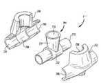
- FIG. 2is a perspective view of an implantable access port in accordance with one embodiment of the present invention shown attached to an artery and a vein;
- FIG. 3is a cross-sectional view of the implantable access port of FIG. 2 taken along section lines A—A;
- FIG. 5is cross-sectional view of an implantable access port in accordance with another embodiment of the present invention.
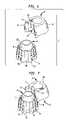
- FIG. 6is a perspective view of an implantable access port in accordance with yet another embodiment of the present invention shown in an unassembled position;
- FIG. 7is a perspective view of the implantable access port of FIG. 6 shown in a partially assembled position
- FIG. 8is an exploded view of another embodiment of the implantable access port of the present invention.
- FIGS. 9 a–dare perspective views depicting one method of installing an implantable access port constructed in accordance with another embodiment of the present invention.
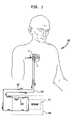
- FIG. 1depicts a diagrammatic view of a typical hemodialysis system utilizing one embodiment of the implantable dialysis access port 2 of the present invention.
- the implantable dialysis port 2may be implanted into the chest area 100 of the human body.
- the implantable dialysis port 2may also be implanted into other areas of the body, so long as it is implanted in reasonable proximity to a medium sized artery, typically between 6 and 8 mm, for use with the implantable dialysis port 2 .
- the implantable dialysis portpreferably comprises an arterial port 4 and a venous port 6 connected to each other in a single structure.
- the ports 4 , 6may be separate structures which may include features to permit their attachment to each other.
- dialysis machines 106may have pumps 108 in series prior to the membrane 110 , rather than after as previously discussed. Because of the pressure gradient between the arterial and venous systems inherent in a mammal, it may also be possible that no pump 108 is required as the patient's heart may be sufficient to circulate blood through the dialysis machine 106 as well as the patient's body.
- FIG. 2depicts a perspective view of an implantable dialysis access port 2 as it is intended to be installed in the human body in accordance with the first embodiment of the present invention.
- the implantable dialysis access port 2preferably comprises an arterial port 4 and a venous port 6 connected to each other or formed together.
- the arterial port 4includes an arterial port casing 8 having an opening 10 through its upper surface 11 .
- An arterial graft 12extends through the arterial port casing 8 .
- the venous port 6includes a venous port casing 14 having an opening 16 through its upper surface 17 .
- a venous graft 18extends from the venous port casing 14 .
- the arterial graft 12comprises a first end 20 , a second end 22 and midsection (not shown).
- the first end 20 and second end 22are each exterior to the arterial port 4 while the midsection (not shown) is disposed within the arterial port casing 8 and in direct fluid communication with opening 10 .
- the first end 20 of the arterial graft 12may be grafted to a medium-sized artery 26 within the human body. This graft is conducted in a surgical procedure and is typically an end to side anastomosis. Procedures of this type are well known in the art.
- second end 22 of arterial graft 12may be grafted to a second portion of artery 26 . This graft is also an end to side anastomosis.
- a self-sealing insert 28such as a rubberized silicone insert or the like, inserted within the opening 10 of arterial port casing 8 prevents this blood from flowing out through the opening 10 of arterial port casing 8 .
- arterial port 4When arterial port 4 is not being used for actual dialysis procedures, blood will continuously flow through arterial graft 12 in a parallel system to that of the blood flowing through artery 26 , and will then continue to flow throughout the remainder of the body. Because none of the blood within arterial graft 12 is permitted to remain stagnant, no clotting should occur.
- the two graftsmay also be conducted in end-to-end anastomosis. In either event, blood will be permitted to continuously flow through the arterial graft 12 , so as to help eliminate clotting therein.
- the implantable dialysis port 2 of the first embodimentalso includes a venous port 6 connected to the arterial port 4 .
- Venous graft 18extending from venous port 6 , comprises a first end 30 and a second end 32 .
- the first end 30is attached to the venous port casing 14 and is in direct fluid communication with opening 16 .
- the second end 32is typically grafted to a vein 34 within the human body in an end to side anastomosis. Connection of the venous graft 18 may also be conducted by a large bore cannulation of a central vein, if so desired.
- the venous graft 18may take the form of a venous catheter and may be inserted directly into a vein 34 so its end 32 may extend into the central venous system.
- venous grafts 18may also be interpreted as allowing for the use of venous catheters as well. Each of these types of connections are well known in the art.
- venous port casing 14also contains a self-sealing insert 36 within its opening 16 .
- This self-sealing insert 36prevents blood from flowing through opening 16 of venous port casing 14 .
- bloodmay freely flow from vein 34 through venous graft 18 .
- venous graft 18is constructed in a “dead end” relationship with venous port 6 , blood may remain stagnant within the venous port 6 and venous graft 18 once the dialysis procedure is completed and the venous port 6 is sealed. It will be appreciated that the likelihood of blood being recycled back to vein 34 from first end 30 of venous graft 18 is inversely proportional to the length of the venous graft.
- the entire track from venous port 6 through venous graft 18is preferably flushed with a saline solution.
- a pre-metered volumeapproximately equal to the volume of the venous graft 18 , of heparin or other anti-clotting agent may then be injected into the venous graft.
- bloodis completely displaced from the venous port 6 , opening 16 and venous graft 18 and is replaced with the anti-clotting agent.
- the anti-clotting agentis permitted to flow from the body through the venous port 6 until fresh blood appears.
- the venous catheter 104may then be connected to the dialysis machine 106 for initiation of the dialysis procedure. Similar procedures are well known in the medical industry. Because of the limited life-span of the self-sealing insert 36 , it is preferred that a single needle be utilized to withdraw the blood, flush the line, and fill the line with heparin.
- the flow of blood through the arterial port 4will generally be in the direction of arrows A, away from the heart, while the flow of blood through venous port 6 will generally be in the direction of arrows B, toward the heart.
- the arterial and venous port casings 8 , 14are generally constructed of a dense material such as plastic, stainless steel, or titanium, so as to be impenetrable by a needle.
- the materialmust also be compatible with implantation within the human body.
- the shape of the port casings 8 , 14must also be compatible with implantation into the human body. Accordingly, there preferably are no sharp edges.
- the arterial and venous grafts 12 , 18must also be constructed of biocompatible material. As well known in the industry, such grafts may be formed from expanded polytetrafluroethylene (PTFE), teflon or polyester.
- PTFEpolytetrafluroethylene
- the opening 10 of arterial port casing 8preferably comprises a plurality of indented regions 38 , or other surface irregularities, into which the self-sealing insert 28 may fit.
- the indented regions 38assist to prevent the self-sealing insert 28 from being pulled from the arterial port casing 8 upon removal of a needle or being pushed into arterial graft 12 upon insertion of a needle, or otherwise becoming dislodged.
- Venous port casing 14 of venous port 6is constructed in much the same manner as arterial port casing 8 of arterial port 4 .
- port casing 6may include a plurality of indented regions 40 for the purpose of securing self-sealing insert 36 there within.
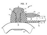
- FIG. 4depicts a more detailed cross sectional view of arterial port 4 in accordance with the first embodiment of the present invention taken along section line B—B of FIG. 1 .
- arterial graft 12contains a branch portion 13 extending into opening 10 of arterial port casing 8 .
- the branch portion 13 of arterial graft 12is either formed integrally with arterial graft 12 during the manufacturing process, or is grafted on in an end to side anastomosis prior to being installed into opening 10 .
- the branch portion 13extends beyond at least one of the indented regions 38 .
- self-sealing membrane 28will preferably provide sufficient pressure to secure branch portion 13 in place.
- Biocompatible adhesivesmay also be applied between the branch portion 13 of arterial graft 12 and the arterial port casing 8 to assist with securing of the branch portion 8 to the arterial port casing.
- Casing 17may also be included between the self-sealing insert 28 and the branch portion 13 of arterial graft 12 .
- the casing 17may be provided to help prevent penetration, tearing, or other damage of the branch portion 13 of arterial graft 12 by the needle used during hemodialysis.
- arterial port casing 8portions of arterial port casing 8 fall below arterial graft 12 in this embodiment of the invention.
- One purpose of having arterial port casing 8 completely surround arterial graft 12is to prevent a needle from piercing through the lower portion 15 of arterial graft 12 when the implantable dialysis port 2 is in use.
- the lower portionalso prevents the arterial graft 12 from collapsing when a needle is inserted into the self-sealing membrane 28 .
- any such needlewill be calibrated so that it is not long enough to puncture the arterial graft 12 , but is long enough to enter the graft and come in contact with the blood flowing therein.
- arterial port casing 8 and venous port casing 14are each shown with securing members 44 .
- Each of these securing members 44extend from the respective arterial or venous port casing 8 , 14 and forms an aperture 46 there within.
- One purpose of the securing member 44is to permit a surgeon to secure the implantable dialysis access port 2 within the body of the patient. Such securing may be conducted by suturing or stapling the securing member to tissue within the patient's body.
- at least two such securing membersare provided per arterial or venous port casings 8 , 14 . This allows for a total of four tie-down points to secure the implantable dialysis port 2 in position, which is typically sufficient to prevent detachment.
- FIG. 5depicts a cross-sectional view of an arterial port casing 4 ′ formed independent of the venous port casing (not shown).
- This port casing 4 ′is otherwise constructed similarly to the port casings previously discussed, complete with self-sealing insert 28 ′, indented regions 38 ′, branch portion 13 ′, casing 17 ′, and arterial graft 12 ′.
- arterial port casings 4 ′ of this typemay be accompanied by separate venous port casings 6 ′.
- FIG. 6depicts an implantable dialysis access port 2 ′ in accordance with a further embodiment of the present invention.
- the arterial port 4 ′ and venous port 6 ′are constructed as two separate elements.
- Each port 4 ′, 6 ′includes a plurality of elongate protruding ribs 50 and a plurality of elongate receiving ribs 48 .
- Each of the protruding ribs 50may flare outward from the respective port 4 ′, 6 ′ to form bulbous extending portions 52 .
- each of the receiving ribs 48may extend inward of the port 4 ′, 6 ′ to form bulbous receiving portions 54 sized and shaped in registration with the bulbous extending portions 52 .
- one port 4 ′, 6 ′includes receiving ribs 48 and protruding ribs 50 alternating around its entire exterior surface while the other port 4 ′, 6 ′ includes such alternating ribs only along a single side, which preferably has a shape corresponding to that of the other element.
- the arterial port casing 8 ′ of arterial port 4 ′includes ribs 48 , 50 around its entire exterior surface while venous port casing 14 ′ of venous port 6 ′ includes such alternating ribs 48 , 50 only along a single side, which has an arcuate surface corresponding to the rounded surface of arterial port 4 .
- the receiving ribs 48 of venous port 6 ′are in registration with the protruding ribs 50 of arterial port 4 ′ and the protruding ribs 50 of venous port 6 ′ are in registration with the receiving ribs 48 of arterial port 4 ′ to facilitate engagement of the two structures. If arterial port 4 ′ is provided with receiving ribs 48 and protruding ribs 50 around its entire exterior surface, it will be appreciated that venous port 6 ′ may then be engaged with arterial port 4 ′ in a number of axes of rotation. Such an arrangement is preferential as it permits a surgeon to strategically place the venous port 6 ′ in relation to the arterial port 4 ′ in accordance with the particularities of the individual into which the implantable dialysis access port 2 ′ is to be implanted.
- the two portsin order to connect to arterial port 4 ′ to the venous port 6 ′, the two ports should be aligned such that the protruding ribs 50 of the venous port 6 ′ align with the receiving ribs 48 of arterial port 4 ′. Once aligned, the venous port 6 ′ may be slid relative to the arterial port 4 ′ to engage the two to each other. It will be appreciated that the bulbous protruding portion 52 will completely fill the bulbous receiving portion 54 of the respective receiving rib 48 .
- the arterial port 4 ′ and the venous port 6 ′may be implanted in different areas of the patient.
- one port 4 ′, 6 ′may be implanted in the left shoulder area while the other port 4 ′, 6 ′ is implanted in the right shoulder area. This will not alter the efficiency of dialysis. Rather, the ports 4 ′, 6 ′ may be implanted in this manner to achieve greater patient comfort. There is no requirement that the ports 4 ′, 6 ′ be in connected to each other, or even in proximity to each other.
- ports 4 ′, 6 ′ shown in FIGS. 6 and 7include an arterial graft (not shown) and a venous graft (not shown), respectively. Neither of these grafts has been shown in FIGS. 6 and 7 for clarity. Notwithstanding, each may be provided in accordance with the techniques previously discussed with respect to the various other embodiments of the present invention.
- the first arterial port half 200 and the second arterial port half 202may be combined to form a complete outer shell of the arterial port 41 ′′.
- Each arterial port half 200 , 202comprises an arcuate portion 206 forming a shaped opening, such as a complete cylinder when combined.
- Each arterial port half 200 , 202also comprises a second arcuate portion 208 forming a chamber generally running perpendicular to the complete cylinder. The chamber and the complete cylinder are in fluid communication with each other, and overlap in portions of each.
- the arterial port core 204comprises a graft 210 extending through a cylindrical lower casing 212 .
- the graft 210may be secured to the cylindrical lower casing 212 with a biocompatible adhesive or mechanically.
- Mounted upon the cylindrical lower casing 212 , or formed integrally therewith,may be a cone-shaped upper section 214 .
- the cone-shaped upper sectionmay be filled with a self-sealing insert 216 , supported therein by surface irregularities or biocompatible adhesives, as in other embodiments of the present invention.
- one half of arterial port core 204may include a venous port coupled to its exterior surface, or may otherwise be adapted to accept a venous port being coupled to its exterior surface.
- the arterial port 411may be implanted into the body of a mammal.
- an arterysuch as artery 26 shown in FIG. 9 a
- the artery 26may be severed in two to form a first artery end 218 and a second artery end 220 , as shown in FIG. 9 b .
- the artery 26is at least a medium sized artery of approximately 6 to 8 mm in diameter. As shown in FIG.
- the graft 210 of the arterial port core 204may be anastamosed to the first artery end 218 and the second artery end 220 such that it is interposed therebetween to permit blood to flow from the first artery end 218 to the graft 210 and then through the second artery end 220 , or vice-versa. Because the entire port is not installed in this step, the gap in the artery may be as little as approximately 2 cm, rather than the approximately 6 cm that would be required if the entire port were implanted at this time.
- the first arterial port half 200 and the second arterial port half 202may then be placed around the combination such that the arcuate portions 206 surround the graft 210 and the second arcuate portions 208 surround the cylindrical lower casing 212 and the cone-shaped upper section 214 . As shown in FIG. 9 d , the fist arterial port half 200 may then be snapped together with the second arterial port half 202 to form the complete arterial port 4 ′′.
- the arterial port 4 ′′may be used in the same manner and for the same procedures as described with regard to other aspects of the present invention, including hemodialysis through puncturing of the semi-permeable membrane 216 .
- the arterial port 4 ′′is preferably of a sufficient length to completely cover and protect the anastomosis between the graft and the artery at each location.
- the implantable dialysis access port 2is typically implanted subcutaneously in the shoulder area below the clavicle, although it may also be implanted elsewhere in the body. It is placed such that the self-sealing insert 28 of arterial port 4 and self-sealing insert 36 of venous port 6 face outward from the chest, just below the surface of the skin.
- these ports 4 , 6are located at slightly different elevations, as shown in FIG. 1 , or are constructed of different geometries, such as shown in FIGS.
- the arterial port 4 ′includes a domed head 56 and the venous port includes a flat upper surface 58 .
- the purpose of providing a distinction between the two ports 4 , 6is so that a dialysis technician, or other medical personnel, may identify each port 4 , 6 during the dialysis procedure by applying slight pressure to the skin with her fingers to discern the elevation and/or shape.
- the arterial port 4should be hooked up to the input of the dialysis machine and the venous port 6 hooked up to the output to take advantage of the pumping power of the patient's heart.
- the first end 20 and second end 22 of arterial graft 12may be grafted to artery 26 .
- Techniques for such end to side graftsare well known in the industry and may be employed. It will also be appreciated that end-to-end anastomosis may also be utilized.
- venous graft 18may be grafted upon vein 34 to permit blood to flow from vein 34 through venous graft 18 which is in direct fluid communication with opening 16 . Blood is prevented from flowing past arterial port casing 8 by virtue of the placement of self-sealing insert 36 .
- the implantable dialysis access portmay be sutured or stapled into its final placement utilizing securing members 44 , as previously discussed. The patient's skin may then be sutured and the patient permitted to heal.
- self-sealing insert 28conforms to the internal shape of the port casing within which it is placed, in this case arterial port casing 8 .
- the self-sealing insert, 28is typically formed from rubberized silicone. Other materials may also be used, so long as the material is sufficiently elastic so as to seal against the back pressure of the blood when the implantable dialysis port 2 is not being used for dialysis, so long as it is compatible with placement inside the human body, and so long as it will self-seal upon removal of a needle, among other required qualities.
- the self-sealing insert 28will be able to remain self-sealing through a lengthy lifespan and numerous needle punctures.
- Dialysis on a patient who has the implantable dialysis access port 2 previously installedis intended to be relatively simple and nearly pain free.
- either the patient or a technicianlocates the implantable dialysis access port 2 just below the surface of the patient's skin. Because the arterial port 4 and venous port 6 are on different elevations, are shaped differently or are at different locations in the body, they can be distinguished from one another easily. Once they are located and distinguished, the patient or technician must pierce the patient's skin and self-sealing membrane 28 of the arterial port 4 with a needle and arterial catheter assembly 102 to permit uncleansed blood from the body to flow into the dialysis machine 106 .
- the patient or technicianmust pierce the patient's skin and the self-sealing membrane 36 of the venous port 6 with a needle and venous catheter assembly 104 to enable cleansed blood from the dialysis machine 106 to be returned to the body.
- Such piercingmay initially be conducted with the aid of a local anesthetic to alleviate any pain the patient may endure.
- a desensitized callousshould form which may then be pierced such that no local anesthesia will be required upon subsequent punctures.
- the needle used for this technical procedureis preferably a side port non-coring type needle.
- This type of needleallows blood to either enter or exit the needle from the side of the needle, but will not cause extensive damage to the self-sealing insert 28 , such as would be caused by a coring type needle.
- the arterial catheter 102 transferring blood from the body to the dialysis machine 106may be removed.
- the venous catheter 204 transferring blood from the dialysis machine 106 to the bodymay be separated from the needle puncturing the self-sealing insert 36 of the venous port 6 .
- the venous port 6may then be flushed with a saline solution.
- a metered amount of anti-clotting agentsuch as heparin, may be injected.
- the heparin injectedshould be sufficient to displace all of the blood from within the venous port 6 and venous graft 18 .
- the heparinshould be sufficient to prevent clotting of blood within these areas between dialysis sessions.
- each of the elements of the implantable dialysis port 2will last for the lifetime of the patient.
- the implantable dialysis port 2may remain in a single implanted location. Nevertheless, if one element fails, it will typically be one of the grafts 12 , 18 . Even if a graft 12 , 18 fails, the implantable dialysis port 2 may remain in the same location after the graft is surgically repaired, using conventional methods known in the medical arts.
- the inventionprovides an arterial port 4 in direct fluid communication with an artery 26 and a venous port 6 in direct fluid communication with a vein 34 .
- Thispermits the invention to be very efficient, as blood is drawn off and returned to different systems within the body.
- itpermits use of dialysis machines with less powerful pumps, as much of the energy required to pump the blood is provided by the heart.
- a pumpwill not be required as the natural pressure gradient between the arterial and venous systems may be sufficient to drive the blood through the complete system. Because an external pump may not be required, the heart may not be subjected to an increased pressure output.
- valvesmay also be utilized. Such valves should serve the purpose of preventing unwanted blood flow from within the port 4 , 6 , while permitting selective entry of a catheter device for blood input or output. Such valves should also be provided with self-sealing abilities.
- a single implantable dialysis portconfigured with a “pass through” type graft such as arterial access port 4
- a single implantable dialysis portmay have uses other than for dialysis.
- Such usesinclude situations where patients require frequent vascular injections or infusions of therapeutic fluids.
- Other usesinclude situations where a patient may require constant monitoring of blood gases or frequent drawing of blood, such as patients relying on in-home cardiac support systems.
- the single portmay be implanted and utilized to assist with the procedures.
Landscapes
- Health & Medical Sciences (AREA)
- Heart & Thoracic Surgery (AREA)
- Vascular Medicine (AREA)
- Hematology (AREA)
- Engineering & Computer Science (AREA)
- Anesthesiology (AREA)
- Biomedical Technology (AREA)
- Life Sciences & Earth Sciences (AREA)
- Animal Behavior & Ethology (AREA)
- General Health & Medical Sciences (AREA)
- Public Health (AREA)
- Veterinary Medicine (AREA)
- Cardiology (AREA)
- Pulmonology (AREA)
- Urology & Nephrology (AREA)
- External Artificial Organs (AREA)
Abstract
Description
Claims (17)
Priority Applications (4)
| Application Number | Priority Date | Filing Date | Title |
|---|---|---|---|
| US10/682,222US7261705B2 (en) | 2002-10-09 | 2003-10-09 | Implantable dialysis access port |
| US11/408,903US7828781B2 (en) | 2002-10-09 | 2006-04-20 | Implantable dialysis access port |
| US11/704,012US20070135775A1 (en) | 2002-10-09 | 2007-02-08 | Implantable dialysis access port |
| US13/555,160US20130072883A1 (en) | 2002-10-09 | 2012-07-22 | Implantable dialysis access port |
Applications Claiming Priority (2)
| Application Number | Priority Date | Filing Date | Title |
|---|---|---|---|
| US41720402P | 2002-10-09 | 2002-10-09 | |
| US10/682,222US7261705B2 (en) | 2002-10-09 | 2003-10-09 | Implantable dialysis access port |
Related Child Applications (2)
| Application Number | Title | Priority Date | Filing Date |
|---|---|---|---|
| US11/408,903Continuation-In-PartUS7828781B2 (en) | 2002-10-09 | 2006-04-20 | Implantable dialysis access port |
| US11/704,012DivisionUS20070135775A1 (en) | 2002-10-09 | 2007-02-08 | Implantable dialysis access port |
Publications (2)
| Publication Number | Publication Date |
|---|---|
| US20040133173A1 US20040133173A1 (en) | 2004-07-08 |
| US7261705B2true US7261705B2 (en) | 2007-08-28 |
Family
ID=32093985
Family Applications (3)
| Application Number | Title | Priority Date | Filing Date |
|---|---|---|---|
| US10/682,222Expired - Fee RelatedUS7261705B2 (en) | 2002-10-09 | 2003-10-09 | Implantable dialysis access port |
| US11/704,012AbandonedUS20070135775A1 (en) | 2002-10-09 | 2007-02-08 | Implantable dialysis access port |
| US13/555,160AbandonedUS20130072883A1 (en) | 2002-10-09 | 2012-07-22 | Implantable dialysis access port |
Family Applications After (2)
| Application Number | Title | Priority Date | Filing Date |
|---|---|---|---|
| US11/704,012AbandonedUS20070135775A1 (en) | 2002-10-09 | 2007-02-08 | Implantable dialysis access port |
| US13/555,160AbandonedUS20130072883A1 (en) | 2002-10-09 | 2012-07-22 | Implantable dialysis access port |
Country Status (4)
| Country | Link |
|---|---|
| US (3) | US7261705B2 (en) |
| EP (1) | EP1565220A4 (en) |
| AU (1) | AU2003282466A1 (en) |
| WO (1) | WO2004032991A2 (en) |
Cited By (44)
| Publication number | Priority date | Publication date | Assignee | Title |
|---|---|---|---|---|
| US20080140025A1 (en)* | 2005-03-04 | 2008-06-12 | C. R. Bard, Inc. | Access port identification systems and methods |
| US20090157014A1 (en)* | 2007-12-17 | 2009-06-18 | William Cook Europe Aps | Device for enabling repeated access to a vessel |
| WO2009140202A1 (en)* | 2008-05-12 | 2009-11-19 | Cardionephrx, Inc. | Implantable fluid separation system |
| US20090287178A1 (en)* | 2008-05-13 | 2009-11-19 | Herbert Curtis B | Interosmolar fluid removal |
| US20100121358A1 (en)* | 2008-06-06 | 2010-05-13 | Vital Access Corporation | Tissue management methods, apparatus, and systems |
| US20100191191A1 (en)* | 2009-01-29 | 2010-07-29 | Vital Access Corporation | Subcutaneous vascular access ports and related systems, methods, and implantation features |
| US7947022B2 (en) | 2005-03-04 | 2011-05-24 | C. R. Bard, Inc. | Access port identification systems and methods |
| US20110147432A1 (en)* | 2004-10-18 | 2011-06-23 | Tyco Healthcare Group Lp D/B/A Covidien | Structure for applying sprayable wound treatment material |
| US20110184347A1 (en)* | 2008-07-25 | 2011-07-28 | Roger Alan Mason | Vascular access device |
| US20110213309A1 (en)* | 2009-01-29 | 2011-09-01 | Vital Access Corporation | Vascular access ports and related methods |
| US8021324B2 (en)* | 2007-07-19 | 2011-09-20 | Medical Components, Inc. | Venous access port assembly with X-ray discernable indicia |
| US8025639B2 (en) | 2005-04-27 | 2011-09-27 | C. R. Bard, Inc. | Methods of power injecting a fluid through an access port |
| US8029482B2 (en) | 2005-03-04 | 2011-10-04 | C. R. Bard, Inc. | Systems and methods for radiographically identifying an access port |
| US8177762B2 (en) | 1998-12-07 | 2012-05-15 | C. R. Bard, Inc. | Septum including at least one identifiable feature, access ports including same, and related methods |
| US8202259B2 (en) | 2005-03-04 | 2012-06-19 | C. R. Bard, Inc. | Systems and methods for identifying an access port |
| US8257325B2 (en) | 2007-06-20 | 2012-09-04 | Medical Components, Inc. | Venous access port with molded and/or radiopaque indicia |
| USD676955S1 (en) | 2010-12-30 | 2013-02-26 | C. R. Bard, Inc. | Implantable access port |
| USD682416S1 (en) | 2010-12-30 | 2013-05-14 | C. R. Bard, Inc. | Implantable access port |
| US20140018721A1 (en)* | 2011-03-16 | 2014-01-16 | Duke University | Arteriovenous Graft for Hemodialysis with Puncture-Resistant Posterior and Side Walls |
| US8641676B2 (en) | 2005-04-27 | 2014-02-04 | C. R. Bard, Inc. | Infusion apparatuses and methods of use |
| US8715244B2 (en) | 2009-07-07 | 2014-05-06 | C. R. Bard, Inc. | Extensible internal bolster for a medical device |
| US8932271B2 (en) | 2008-11-13 | 2015-01-13 | C. R. Bard, Inc. | Implantable medical devices including septum-based indicators |
| US9079004B2 (en) | 2009-11-17 | 2015-07-14 | C. R. Bard, Inc. | Overmolded access port including anchoring and identification features |
| US9265912B2 (en) | 2006-11-08 | 2016-02-23 | C. R. Bard, Inc. | Indicia informative of characteristics of insertable medical devices |
| US9427218B2 (en) | 2010-03-09 | 2016-08-30 | Solinas Medical Inc. | Self-closing devices and methods for making and using them |
| US9474888B2 (en) | 2005-03-04 | 2016-10-25 | C. R. Bard, Inc. | Implantable access port including a sandwiched radiopaque insert |
| US9579496B2 (en) | 2007-11-07 | 2017-02-28 | C. R. Bard, Inc. | Radiopaque and septum-based indicators for a multi-lumen implantable port |
| US9610432B2 (en) | 2007-07-19 | 2017-04-04 | Innovative Medical Devices, Llc | Venous access port assembly with X-ray discernable indicia |
| US9642986B2 (en) | 2006-11-08 | 2017-05-09 | C. R. Bard, Inc. | Resource information key for an insertable medical device |
| US10307581B2 (en) | 2005-04-27 | 2019-06-04 | C. R. Bard, Inc. | Reinforced septum for an implantable medical device |
| US10406274B1 (en) | 2017-06-02 | 2019-09-10 | Jose Ramirez | Accessing assembly for hemodialysis administration |
| US10463845B2 (en) | 2013-01-23 | 2019-11-05 | C.R. Bard, Inc. | Low-profile access port |
| USD870264S1 (en) | 2017-09-06 | 2019-12-17 | C. R. Bard, Inc. | Implantable apheresis port |
| US10596017B2 (en) | 2016-04-25 | 2020-03-24 | Solinas Medical Inc. | Self-sealing tubular grafts, patches, and methods for making and using them |
| US10595888B2 (en) | 2013-04-13 | 2020-03-24 | Solinas Medical Inc. | Self-closing devices and apparatus and methods for making and delivering them |
| US10905867B2 (en) | 2015-05-06 | 2021-02-02 | Voyager Biomedical, Inc. | Vascular access channel and methods |
| US11065377B2 (en) | 2017-03-31 | 2021-07-20 | InnAVasc Medical, Inc. | Apparatus and method for cannulation of vascular access graft |
| US11197952B2 (en) | 2009-01-29 | 2021-12-14 | Advent Access Pte. Ltd. | Vascular access ports and related methods |
| US11420033B2 (en) | 2013-01-23 | 2022-08-23 | C. R. Bard, Inc. | Low-profile single and dual vascular access device |
| US11464960B2 (en) | 2013-01-23 | 2022-10-11 | C. R. Bard, Inc. | Low-profile single and dual vascular access device |
| US11890443B2 (en) | 2008-11-13 | 2024-02-06 | C. R. Bard, Inc. | Implantable medical devices including septum-based indicators |
| US11925782B2 (en) | 2018-10-30 | 2024-03-12 | InnAVasc Medical, Inc. | Apparatus and method for cannulation of vascular access vessel |
| US12017413B2 (en)* | 2016-06-10 | 2024-06-25 | Xeltis Ag | System for producing a graft device with a three dimensional covering |
| US12383708B2 (en) | 2020-01-16 | 2025-08-12 | Stratos Medical Limited | Medical device |
Families Citing this family (42)
| Publication number | Priority date | Publication date | Assignee | Title |
|---|---|---|---|---|
| US8574204B2 (en)* | 2002-10-21 | 2013-11-05 | Angiodynamics, Inc. | Implantable medical device for improved placement and adherence in the body |
| US20040162607A1 (en)* | 2002-12-30 | 2004-08-19 | Saqib Masroor | Prosthetic arterial graft with test port |
| US20040215125A1 (en)* | 2003-04-27 | 2004-10-28 | Brown Donald W. | Bifurcated graft for dialysis |
| US7762977B2 (en) | 2003-10-08 | 2010-07-27 | Hemosphere, Inc. | Device and method for vascular access |
| US20050137614A1 (en)* | 2003-10-08 | 2005-06-23 | Porter Christopher H. | System and method for connecting implanted conduits |
| US20070167901A1 (en)* | 2005-11-17 | 2007-07-19 | Herrig Judson A | Self-sealing residual compressive stress graft for dialysis |
| US20110295181A1 (en) | 2008-03-05 | 2011-12-01 | Hemosphere, Inc. | Implantable and removable customizable body conduit |
| JP5492792B2 (en)* | 2008-03-05 | 2014-05-14 | ヘモスフィア,インコーポレイテッド | Vascular access system |
| US8075536B2 (en)* | 2008-09-09 | 2011-12-13 | Navilyst Medical, Inc. | Power injectable port identification |
| MX2012005113A (en)* | 2009-10-27 | 2012-08-03 | Medical Components Inc | Multi-port assembly. |
| US9555174B2 (en) | 2010-02-17 | 2017-01-31 | Flow Forward Medical, Inc. | Blood pump systems and methods |
| US9662431B2 (en) | 2010-02-17 | 2017-05-30 | Flow Forward Medical, Inc. | Blood pump systems and methods |
| KR101845213B1 (en) | 2010-02-17 | 2018-05-18 | 플로우 포워드 메디컬, 인크. | System and method to increase the overall diameter of veins |
| US8882694B2 (en) | 2011-06-03 | 2014-11-11 | The Johns Hopkins University | Implantable three-way diaphragm valve |
| EP2744539B1 (en) | 2011-08-17 | 2022-11-02 | Artio Medical, Inc. | System to increase the overall diameter of a peripheral artery |
| KR102062132B1 (en) | 2011-08-17 | 2020-01-03 | 플로우 포워드 메디컬, 인크. | Blood pump systems and methods |
| JP6199866B2 (en) | 2011-09-06 | 2017-09-20 | メリット・メディカル・システムズ・インコーポレイテッドMerit Medical Systems,Inc. | Vascular access system having a connecting portion |
| US9707339B2 (en) | 2012-03-28 | 2017-07-18 | Angiodynamics, Inc. | High flow rate dual reservoir port system |
| US9713704B2 (en) | 2012-03-29 | 2017-07-25 | Bradley D. Chartrand | Port reservoir cleaning system and method |
| US10258730B2 (en) | 2012-08-17 | 2019-04-16 | Flow Forward Medical, Inc. | Blood pump systems and methods |
| US9205242B2 (en) | 2012-11-19 | 2015-12-08 | Angiodynamics, Inc. | Port septum with integral valve |
| WO2015066055A1 (en)* | 2013-10-28 | 2015-05-07 | Abbvie Inc. | Systems and methods for covering tubing connections |
| US10682453B2 (en) | 2013-12-20 | 2020-06-16 | Merit Medical Systems, Inc. | Vascular access system with reinforcement member |
| US10166321B2 (en) | 2014-01-09 | 2019-01-01 | Angiodynamics, Inc. | High-flow port and infusion needle systems |
| AU2017257508B2 (en) | 2016-04-29 | 2021-10-14 | Artio Medical, Inc. | Conduit tips and systems and methods for use |
| WO2018089625A2 (en) | 2016-11-10 | 2018-05-17 | Merit Medical Systems, Inc. | Anchor device for vascular anastomosis |
| US11383072B2 (en) | 2017-01-12 | 2022-07-12 | Merit Medical Systems, Inc. | Methods and systems for selection and use of connectors between conduits |
| EP4461262A3 (en) | 2017-01-25 | 2025-02-26 | Merit Medical Systems, Inc. | Systems for facilitating laminar flow between conduits |
| US11026704B2 (en) | 2017-03-06 | 2021-06-08 | Merit Medical Systems, Inc. | Vascular access assembly declotting systems and methods |
| US10925710B2 (en) | 2017-03-24 | 2021-02-23 | Merit Medical Systems, Inc. | Subcutaneous vascular assemblies for improving blood flow and related devices and methods |
| WO2019014444A2 (en) | 2017-07-14 | 2019-01-17 | Merit Medical Systems, Inc. | Releasable conduit connectors |
| US11911585B2 (en) | 2017-07-20 | 2024-02-27 | Merit Medical Systems, Inc. | Methods and systems for coupling conduits |
| US11331458B2 (en) | 2017-10-31 | 2022-05-17 | Merit Medical Systems, Inc. | Subcutaneous vascular assemblies for improving blood flow and related devices and methods |
| CN111954548A (en)* | 2018-02-21 | 2020-11-17 | 亚克安娜生命科学有限公司 | Fluid delivery system and method |
| GB2575093B (en)* | 2018-06-29 | 2022-08-17 | Spectrum Medical Ltd | Seal |
| DE102018133404A1 (en) | 2018-12-21 | 2020-06-25 | B.Braun Avitum Ag | Vascular access implant and access implant system |
| US20220008706A1 (en)* | 2020-07-08 | 2022-01-13 | Portal Access, Inc. | Minimally invasive port implantation |
| CA3202542A1 (en)* | 2020-11-19 | 2022-05-27 | Voyager Biomedical, Inc. | Vascular access device with vessel accomodation |
| CN113599620A (en)* | 2021-09-18 | 2021-11-05 | 康迪泰科(北京)医疗科技有限公司 | Implantable drug delivery device |
| WO2024050005A2 (en)* | 2022-09-01 | 2024-03-07 | Icahn School Of Medicine At Mount Sinai | Implantable access port device for localized treatments and measurements, and method of using same |
| WO2024218211A1 (en)* | 2023-04-18 | 2024-10-24 | Region Syddanmark | An improved hemodialysis device |
| ES3015248A1 (en)* | 2023-10-27 | 2025-04-30 | Klus Life Systems S L U | DEVICE FOR CHANNELING BLOOD FOR HEMODIALYSIS |
Citations (24)
| Publication number | Priority date | Publication date | Assignee | Title |
|---|---|---|---|---|
| US4113806A (en) | 1976-08-30 | 1978-09-12 | Exxon Research & Engineering Co. | Polypropylene impact blends having improved optical properties |
| US4221882A (en) | 1979-01-31 | 1980-09-09 | Exxon Research & Engineering Co. | High impact melt-flowable dual continuum melt mixed polymer blends of polypropylene, polyethylene, and ethylene-propylene rubber |
| US4251646A (en) | 1979-07-27 | 1981-02-17 | Exxon Research & Engineering Co. | Thermoplastic blend of polypropylene, EPM and propylene-ethylene copolymer |
| US4296022A (en) | 1980-06-04 | 1981-10-20 | Chevron Research | Polypropylene blend compositions |
| US4311628A (en) | 1977-11-09 | 1982-01-19 | Monsanto Company | Thermoplastic elastomeric blends of olefin rubber and polyolefin resin |
| US4316970A (en) | 1980-08-01 | 1982-02-23 | Shell Oil Company | Blends of butene-1-ethylene copolymer and polypropylene |
| US4496350A (en)* | 1980-04-08 | 1985-01-29 | Renal Systems, Inc. | Blood access device |
| US4632881A (en) | 1984-10-12 | 1986-12-30 | Olin Corporation | Pyrithione-containing bioactive polymers and their use in paint and wood perservative products |
| US4634739A (en) | 1984-12-27 | 1987-01-06 | E. I. Du Pont De Nemours And Company | Blend of polyethylene and polypropylene |
| US4774277A (en) | 1982-03-26 | 1988-09-27 | Exxon Research & Engineering Co. | Blends of polyolefin plastics with elastomeric plasticizers |
| US4804714A (en) | 1987-11-20 | 1989-02-14 | Union Carbide Corporation | Polyolefin blends |
| US4846806A (en) | 1987-10-06 | 1989-07-11 | 501 Regents Of University Of Minnesota | Implantable intravascular access system |
| US4892518A (en) | 1987-12-04 | 1990-01-09 | Biocontrol Technology, Inc. | Hemodialysis |
| US4929681A (en) | 1985-12-30 | 1990-05-29 | Mobil Oil Corporation | Blends of LLDPE, polypropylene and aromatic polymers and high modulus films thereof |
| US4950259A (en) | 1987-10-12 | 1990-08-21 | Hsc Research Development Corporation | Peritoneal dialysis catheter suitable for permanent implant |
| US5037385A (en) | 1988-10-24 | 1991-08-06 | National Research Development Corporation | Continuous ambulatory peritoneal dialysis method |
| US5562617A (en) | 1994-01-18 | 1996-10-08 | Finch, Jr.; Charles D. | Implantable vascular device |
| US5562618A (en) | 1994-01-21 | 1996-10-08 | Sims Deltec, Inc. | Portal assembly and catheter connector |
| US5792104A (en) | 1996-12-10 | 1998-08-11 | Medtronic, Inc. | Dual-reservoir vascular access port |
| US5833654A (en) | 1997-01-17 | 1998-11-10 | C. R. Bard, Inc. | Longitudinally aligned dual reservoir access port |
| US5944688A (en) | 1998-07-20 | 1999-08-31 | Lois; William A | Implantable hemodialysis access port assembly |
| US6022335A (en) | 1998-07-01 | 2000-02-08 | Ramadan; Hossein | Implantable hemodialysis triple port assembly |
| US6053891A (en)* | 1996-08-26 | 2000-04-25 | Decampli; William M. | Apparatus and methods for providing selectively adjustable blood flow through a vascular graft |
| US6261257B1 (en)* | 1998-05-26 | 2001-07-17 | Renan P. Uflacker | Dialysis graft system with self-sealing access ports |
Family Cites Families (6)
| Publication number | Priority date | Publication date | Assignee | Title |
|---|---|---|---|---|
| FR2558403A1 (en)* | 1984-01-24 | 1985-07-26 | Thiolet Damien | Tongs for fitting together and taking apart two pieces and their particular application in the medical field |
| US5328461A (en)* | 1992-04-30 | 1994-07-12 | Utterberg David S | Blow molded venous drip chamber for hemodialysis |
| US5647855A (en)* | 1992-05-06 | 1997-07-15 | Trooskin; Stanley Z. | Self-healing diaphragm in a subcutaneous infusion port |
| US6053901A (en)* | 1994-01-18 | 2000-04-25 | Vasca, Inc. | Subcutaneously implanted cannula and method for arterial access |
| US7033339B1 (en)* | 1998-05-29 | 2006-04-25 | Becton Dickinson And Company (Part Interest) | Self sealing luer receiving stopcock |
| US6102884A (en)* | 1997-02-07 | 2000-08-15 | Squitieri; Rafael | Squitieri hemodialysis and vascular access systems |
- 2003
- 2003-10-09WOPCT/US2003/031828patent/WO2004032991A2/ennot_activeApplication Discontinuation
- 2003-10-09USUS10/682,222patent/US7261705B2/ennot_activeExpired - Fee Related
- 2003-10-09AUAU2003282466Apatent/AU2003282466A1/ennot_activeAbandoned
- 2003-10-09EPEP03774659Apatent/EP1565220A4/ennot_activeWithdrawn
- 2007
- 2007-02-08USUS11/704,012patent/US20070135775A1/ennot_activeAbandoned
- 2012
- 2012-07-22USUS13/555,160patent/US20130072883A1/ennot_activeAbandoned
Patent Citations (24)
| Publication number | Priority date | Publication date | Assignee | Title |
|---|---|---|---|---|
| US4113806A (en) | 1976-08-30 | 1978-09-12 | Exxon Research & Engineering Co. | Polypropylene impact blends having improved optical properties |
| US4311628A (en) | 1977-11-09 | 1982-01-19 | Monsanto Company | Thermoplastic elastomeric blends of olefin rubber and polyolefin resin |
| US4221882A (en) | 1979-01-31 | 1980-09-09 | Exxon Research & Engineering Co. | High impact melt-flowable dual continuum melt mixed polymer blends of polypropylene, polyethylene, and ethylene-propylene rubber |
| US4251646A (en) | 1979-07-27 | 1981-02-17 | Exxon Research & Engineering Co. | Thermoplastic blend of polypropylene, EPM and propylene-ethylene copolymer |
| US4496350A (en)* | 1980-04-08 | 1985-01-29 | Renal Systems, Inc. | Blood access device |
| US4296022A (en) | 1980-06-04 | 1981-10-20 | Chevron Research | Polypropylene blend compositions |
| US4316970A (en) | 1980-08-01 | 1982-02-23 | Shell Oil Company | Blends of butene-1-ethylene copolymer and polypropylene |
| US4774277A (en) | 1982-03-26 | 1988-09-27 | Exxon Research & Engineering Co. | Blends of polyolefin plastics with elastomeric plasticizers |
| US4632881A (en) | 1984-10-12 | 1986-12-30 | Olin Corporation | Pyrithione-containing bioactive polymers and their use in paint and wood perservative products |
| US4634739A (en) | 1984-12-27 | 1987-01-06 | E. I. Du Pont De Nemours And Company | Blend of polyethylene and polypropylene |
| US4929681A (en) | 1985-12-30 | 1990-05-29 | Mobil Oil Corporation | Blends of LLDPE, polypropylene and aromatic polymers and high modulus films thereof |
| US4846806A (en) | 1987-10-06 | 1989-07-11 | 501 Regents Of University Of Minnesota | Implantable intravascular access system |
| US4950259A (en) | 1987-10-12 | 1990-08-21 | Hsc Research Development Corporation | Peritoneal dialysis catheter suitable for permanent implant |
| US4804714A (en) | 1987-11-20 | 1989-02-14 | Union Carbide Corporation | Polyolefin blends |
| US4892518A (en) | 1987-12-04 | 1990-01-09 | Biocontrol Technology, Inc. | Hemodialysis |
| US5037385A (en) | 1988-10-24 | 1991-08-06 | National Research Development Corporation | Continuous ambulatory peritoneal dialysis method |
| US5562617A (en) | 1994-01-18 | 1996-10-08 | Finch, Jr.; Charles D. | Implantable vascular device |
| US5562618A (en) | 1994-01-21 | 1996-10-08 | Sims Deltec, Inc. | Portal assembly and catheter connector |
| US6053891A (en)* | 1996-08-26 | 2000-04-25 | Decampli; William M. | Apparatus and methods for providing selectively adjustable blood flow through a vascular graft |
| US5792104A (en) | 1996-12-10 | 1998-08-11 | Medtronic, Inc. | Dual-reservoir vascular access port |
| US5833654A (en) | 1997-01-17 | 1998-11-10 | C. R. Bard, Inc. | Longitudinally aligned dual reservoir access port |
| US6261257B1 (en)* | 1998-05-26 | 2001-07-17 | Renan P. Uflacker | Dialysis graft system with self-sealing access ports |
| US6022335A (en) | 1998-07-01 | 2000-02-08 | Ramadan; Hossein | Implantable hemodialysis triple port assembly |
| US5944688A (en) | 1998-07-20 | 1999-08-31 | Lois; William A | Implantable hemodialysis access port assembly |
Cited By (123)
| Publication number | Priority date | Publication date | Assignee | Title |
|---|---|---|---|---|
| US8608713B2 (en) | 1998-12-07 | 2013-12-17 | C. R. Bard, Inc. | Septum feature for identification of an access port |
| US8177762B2 (en) | 1998-12-07 | 2012-05-15 | C. R. Bard, Inc. | Septum including at least one identifiable feature, access ports including same, and related methods |
| US20110147432A1 (en)* | 2004-10-18 | 2011-06-23 | Tyco Healthcare Group Lp D/B/A Covidien | Structure for applying sprayable wound treatment material |
| US8821523B2 (en)* | 2004-10-18 | 2014-09-02 | Covidien Lp | Structure for applying sprayable wound treatment material |
| US9474888B2 (en) | 2005-03-04 | 2016-10-25 | C. R. Bard, Inc. | Implantable access port including a sandwiched radiopaque insert |
| US9682186B2 (en) | 2005-03-04 | 2017-06-20 | C. R. Bard, Inc. | Access port identification systems and methods |
| US10905868B2 (en) | 2005-03-04 | 2021-02-02 | Bard Peripheral Vascular, Inc. | Systems and methods for radiographically identifying an access port |
| US10857340B2 (en) | 2005-03-04 | 2020-12-08 | Bard Peripheral Vascular, Inc. | Systems and methods for radiographically identifying an access port |
| US7785302B2 (en) | 2005-03-04 | 2010-08-31 | C. R. Bard, Inc. | Access port identification systems and methods |
| US7947022B2 (en) | 2005-03-04 | 2011-05-24 | C. R. Bard, Inc. | Access port identification systems and methods |
| US7959615B2 (en) | 2005-03-04 | 2011-06-14 | C. R. Bard, Inc. | Access port identification systems and methods |
| US8998860B2 (en) | 2005-03-04 | 2015-04-07 | C. R. Bard, Inc. | Systems and methods for identifying an access port |
| US10238850B2 (en) | 2005-03-04 | 2019-03-26 | Bard Peripheral Vascular, Inc. | Systems and methods for radiographically identifying an access port |
| US10675401B2 (en) | 2005-03-04 | 2020-06-09 | Bard Peripheral Vascular, Inc. | Access port identification systems and methods |
| US8939947B2 (en) | 2005-03-04 | 2015-01-27 | C. R. Bard, Inc. | Systems and methods for radiographically identifying an access port |
| US11077291B2 (en) | 2005-03-04 | 2021-08-03 | Bard Peripheral Vascular, Inc. | Implantable access port including a sandwiched radiopaque insert |
| US8029482B2 (en) | 2005-03-04 | 2011-10-04 | C. R. Bard, Inc. | Systems and methods for radiographically identifying an access port |
| US9603992B2 (en) | 2005-03-04 | 2017-03-28 | C. R. Bard, Inc. | Access port identification systems and methods |
| US8202259B2 (en) | 2005-03-04 | 2012-06-19 | C. R. Bard, Inc. | Systems and methods for identifying an access port |
| US20080140025A1 (en)* | 2005-03-04 | 2008-06-12 | C. R. Bard, Inc. | Access port identification systems and methods |
| US10179230B2 (en) | 2005-03-04 | 2019-01-15 | Bard Peripheral Vascular, Inc. | Systems and methods for radiographically identifying an access port |
| US9603993B2 (en) | 2005-03-04 | 2017-03-28 | C. R. Bard, Inc. | Access port identification systems and methods |
| US8603052B2 (en) | 2005-03-04 | 2013-12-10 | C. R. Bard, Inc. | Access port identification systems and methods |
| US8382723B2 (en) | 2005-03-04 | 2013-02-26 | C. R. Bard, Inc. | Access port identification systems and methods |
| US8585663B2 (en) | 2005-03-04 | 2013-11-19 | C. R. Bard, Inc. | Access port identification systems and methods |
| US8382724B2 (en) | 2005-03-04 | 2013-02-26 | C. R. Bard, Inc. | Systems and methods for radiographically identifying an access port |
| US10265512B2 (en) | 2005-03-04 | 2019-04-23 | Bard Peripheral Vascular, Inc. | Implantable access port including a sandwiched radiopaque insert |
| US10780257B2 (en) | 2005-04-27 | 2020-09-22 | Bard Peripheral Vascular, Inc. | Assemblies for identifying a power injectable access port |
| US10183157B2 (en) | 2005-04-27 | 2019-01-22 | Bard Peripheral Vascular, Inc. | Assemblies for identifying a power injectable access port |
| US8475417B2 (en) | 2005-04-27 | 2013-07-02 | C. R. Bard, Inc. | Assemblies for identifying a power injectable access port |
| US8545460B2 (en) | 2005-04-27 | 2013-10-01 | C. R. Bard, Inc. | Infusion apparatuses and related methods |
| US10307581B2 (en) | 2005-04-27 | 2019-06-04 | C. R. Bard, Inc. | Reinforced septum for an implantable medical device |
| US9937337B2 (en) | 2005-04-27 | 2018-04-10 | C. R. Bard, Inc. | Assemblies for identifying a power injectable access port |
| US10625065B2 (en) | 2005-04-27 | 2020-04-21 | Bard Peripheral Vascular, Inc. | Assemblies for identifying a power injectable access port |
| US9421352B2 (en) | 2005-04-27 | 2016-08-23 | C. R. Bard, Inc. | Infusion apparatuses and methods of use |
| US8641676B2 (en) | 2005-04-27 | 2014-02-04 | C. R. Bard, Inc. | Infusion apparatuses and methods of use |
| US8641688B2 (en) | 2005-04-27 | 2014-02-04 | C. R. Bard, Inc. | Assemblies for identifying a power injectable access port |
| US10016585B2 (en) | 2005-04-27 | 2018-07-10 | Bard Peripheral Vascular, Inc. | Assemblies for identifying a power injectable access port |
| US8805478B2 (en) | 2005-04-27 | 2014-08-12 | C. R. Bard, Inc. | Methods of performing a power injection procedure including identifying features of a subcutaneously implanted access port for delivery of contrast media |
| US8025639B2 (en) | 2005-04-27 | 2011-09-27 | C. R. Bard, Inc. | Methods of power injecting a fluid through an access port |
| US10661068B2 (en) | 2005-04-27 | 2020-05-26 | Bard Peripheral Vascular, Inc. | Assemblies for identifying a power injectable access port |
| US10052470B2 (en) | 2005-04-27 | 2018-08-21 | Bard Peripheral Vascular, Inc. | Assemblies for identifying a power injectable access port |
| US11878137B2 (en) | 2006-10-18 | 2024-01-23 | Medical Components, Inc. | Venous access port assembly with X-ray discernable indicia |
| US9642986B2 (en) | 2006-11-08 | 2017-05-09 | C. R. Bard, Inc. | Resource information key for an insertable medical device |
| US9265912B2 (en) | 2006-11-08 | 2016-02-23 | C. R. Bard, Inc. | Indicia informative of characteristics of insertable medical devices |
| US10092725B2 (en) | 2006-11-08 | 2018-10-09 | C. R. Bard, Inc. | Resource information key for an insertable medical device |
| US10556090B2 (en) | 2006-11-08 | 2020-02-11 | C. R. Bard, Inc. | Resource information key for an insertable medical device |
| US8852160B2 (en) | 2007-06-20 | 2014-10-07 | Medical Components, Inc. | Venous access port with molded and/or radiopaque indicia |
| US11478622B2 (en) | 2007-06-20 | 2022-10-25 | Medical Components, Inc. | Venous access port with molded and/or radiopaque indicia |
| US11938296B2 (en) | 2007-06-20 | 2024-03-26 | Medical Components, Inc. | Venous access port with molded and/or radiopaque indicia |
| US9533133B2 (en) | 2007-06-20 | 2017-01-03 | Medical Components, Inc. | Venous access port with molded and/or radiopaque indicia |
| US11406808B2 (en) | 2007-06-20 | 2022-08-09 | Medical Components, Inc. | Venous access port with molded and/or radiopaque indicia |
| US8257325B2 (en) | 2007-06-20 | 2012-09-04 | Medical Components, Inc. | Venous access port with molded and/or radiopaque indicia |
| US10639465B2 (en) | 2007-07-19 | 2020-05-05 | Innovative Medical Devices, Llc | Venous access port assembly with X-ray discernable indicia |
| US8021324B2 (en)* | 2007-07-19 | 2011-09-20 | Medical Components, Inc. | Venous access port assembly with X-ray discernable indicia |
| US10874842B2 (en) | 2007-07-19 | 2020-12-29 | Medical Components, Inc. | Venous access port assembly with X-ray discernable indicia |
| US9517329B2 (en) | 2007-07-19 | 2016-12-13 | Medical Components, Inc. | Venous access port assembly with X-ray discernable indicia |
| US9610432B2 (en) | 2007-07-19 | 2017-04-04 | Innovative Medical Devices, Llc | Venous access port assembly with X-ray discernable indicia |
| US11638810B2 (en) | 2007-11-07 | 2023-05-02 | C. R. Bard, Inc. | Radiopaque and septum-based indicators for a multi-lumen implantable port |
| US10792485B2 (en) | 2007-11-07 | 2020-10-06 | C. R. Bard, Inc. | Radiopaque and septum-based indicators for a multi-lumen implantable port |
| US9579496B2 (en) | 2007-11-07 | 2017-02-28 | C. R. Bard, Inc. | Radiopaque and septum-based indicators for a multi-lumen implantable port |
| US10086186B2 (en) | 2007-11-07 | 2018-10-02 | C. R. Bard, Inc. | Radiopaque and septum-based indicators for a multi-lumen implantable port |
| US9440058B2 (en)* | 2007-12-17 | 2016-09-13 | Cook Medical Technologies, LLC | Device for enabling repeated access to a vessel |
| US20090157014A1 (en)* | 2007-12-17 | 2009-06-18 | William Cook Europe Aps | Device for enabling repeated access to a vessel |
| WO2009140202A1 (en)* | 2008-05-12 | 2009-11-19 | Cardionephrx, Inc. | Implantable fluid separation system |
| US20090287178A1 (en)* | 2008-05-13 | 2009-11-19 | Herbert Curtis B | Interosmolar fluid removal |
| US8211053B2 (en) | 2008-05-13 | 2012-07-03 | Equilibrate, Llc | Interosmolar fluid removal |
| US11134950B2 (en) | 2008-06-06 | 2021-10-05 | Advent Access Pte. Ltd. | Methods of attaching an implant to a vessel |
| US9039717B2 (en) | 2008-06-06 | 2015-05-26 | Vital Access Corporation | Tissue management apparatus for vascular access |
| US20100121358A1 (en)* | 2008-06-06 | 2010-05-13 | Vital Access Corporation | Tissue management methods, apparatus, and systems |
| US8409228B2 (en) | 2008-06-06 | 2013-04-02 | Duane D. Blatter | Tissue management methods, apparatus, and systems |
| US20110184347A1 (en)* | 2008-07-25 | 2011-07-28 | Roger Alan Mason | Vascular access device |
| US8414530B2 (en)* | 2008-07-25 | 2013-04-09 | Roger Alan Mason | Vascular access device |
| US8932271B2 (en) | 2008-11-13 | 2015-01-13 | C. R. Bard, Inc. | Implantable medical devices including septum-based indicators |
| US10052471B2 (en) | 2008-11-13 | 2018-08-21 | C. R. Bard, Inc. | Implantable medical devices including septum-based indicators |
| US10773066B2 (en) | 2008-11-13 | 2020-09-15 | C. R. Bard, Inc. | Implantable medical devices including septum-based indicators |
| US11890443B2 (en) | 2008-11-13 | 2024-02-06 | C. R. Bard, Inc. | Implantable medical devices including septum-based indicators |
| US20100191191A1 (en)* | 2009-01-29 | 2010-07-29 | Vital Access Corporation | Subcutaneous vascular access ports and related systems, methods, and implantation features |
| US10894120B2 (en) | 2009-01-29 | 2021-01-19 | Advent Access Pte. Ltd. | Vascular access port systems and methods |
| US9603988B2 (en) | 2009-01-29 | 2017-03-28 | Vital Access Corporation | Subcutaneous vascular access ports |
| US10265458B2 (en) | 2009-01-29 | 2019-04-23 | Advent Access Pte. Ltd. | Vascular access ports and related methods |
| US9179901B2 (en) | 2009-01-29 | 2015-11-10 | Vital Access Corporation | Vascular access ports and related methods |
| US20150258322A1 (en)* | 2009-01-29 | 2015-09-17 | Vital Access Corporation | Vascular access port systems and methods |
| US11197952B2 (en) | 2009-01-29 | 2021-12-14 | Advent Access Pte. Ltd. | Vascular access ports and related methods |
| US9072880B2 (en) | 2009-01-29 | 2015-07-07 | Vital Access Corporation | Subcutaneous vascular access ports and related systems and methods |
| US20100191166A1 (en)* | 2009-01-29 | 2010-07-29 | Vital Access Corporation | Subcutaneous vascular access ports and related systems and methods |
| US8337464B2 (en) | 2009-01-29 | 2012-12-25 | Vital Access Corporation | Vascular access ports and related methods |
| US10226564B2 (en)* | 2009-01-29 | 2019-03-12 | Advent Access Pte. Ltd. | Vascular access port systems and methods |
| WO2010088541A1 (en)* | 2009-01-29 | 2010-08-05 | Vital Access Corporation | Subcutaneous vascular access ports and related systems and methods |
| US8337465B2 (en) | 2009-01-29 | 2012-12-25 | Vital Access Corporation | Subcutaneous vascular access ports and related systems, methods, and implantation features |
| US9968726B2 (en) | 2009-01-29 | 2018-05-15 | Df Vital Holdings, Llc | Methods for implanting subcutaneous vascular access ports |
| US9033931B2 (en) | 2009-01-29 | 2015-05-19 | Vital Access Corporation | Subcutaneous vascular access ports having attachment features |
| US10773010B2 (en) | 2009-01-29 | 2020-09-15 | Advent Access Pte. Ltd. | Subcutaneous vascular access ports and related systems and methods |
| US20110213309A1 (en)* | 2009-01-29 | 2011-09-01 | Vital Access Corporation | Vascular access ports and related methods |
| US8715244B2 (en) | 2009-07-07 | 2014-05-06 | C. R. Bard, Inc. | Extensible internal bolster for a medical device |
| US10912935B2 (en) | 2009-11-17 | 2021-02-09 | Bard Peripheral Vascular, Inc. | Method for manufacturing a power-injectable access port |
| US9248268B2 (en) | 2009-11-17 | 2016-02-02 | C. R. Bard, Inc. | Overmolded access port including anchoring and identification features |
| US9717895B2 (en) | 2009-11-17 | 2017-08-01 | C. R. Bard, Inc. | Overmolded access port including anchoring and identification features |
| US11759615B2 (en) | 2009-11-17 | 2023-09-19 | Bard Peripheral Vascular, Inc. | Overmolded access port including anchoring and identification features |
| US10155101B2 (en) | 2009-11-17 | 2018-12-18 | Bard Peripheral Vascular, Inc. | Overmolded access port including anchoring and identification features |
| US9079004B2 (en) | 2009-11-17 | 2015-07-14 | C. R. Bard, Inc. | Overmolded access port including anchoring and identification features |
| US9427218B2 (en) | 2010-03-09 | 2016-08-30 | Solinas Medical Inc. | Self-closing devices and methods for making and using them |
| USD682416S1 (en) | 2010-12-30 | 2013-05-14 | C. R. Bard, Inc. | Implantable access port |
| USD676955S1 (en) | 2010-12-30 | 2013-02-26 | C. R. Bard, Inc. | Implantable access port |
| US20140018721A1 (en)* | 2011-03-16 | 2014-01-16 | Duke University | Arteriovenous Graft for Hemodialysis with Puncture-Resistant Posterior and Side Walls |
| US9585998B2 (en)* | 2011-03-16 | 2017-03-07 | Duke University | Arteriovenous graft for hemodialysis with puncture-resistant posterior and side walls |
| US11504461B2 (en)* | 2011-03-16 | 2022-11-22 | W. L. Gore & Associates, Inc. | Arteriovenous graft for hemodialysis with puncture-resistant posterior and side walls |
| US10420874B2 (en)* | 2011-03-16 | 2019-09-24 | Duke University | Arteriovenous graft for hemodialysis with puncture-resistant posterior and side walls |
| US11420033B2 (en) | 2013-01-23 | 2022-08-23 | C. R. Bard, Inc. | Low-profile single and dual vascular access device |
| US10463845B2 (en) | 2013-01-23 | 2019-11-05 | C.R. Bard, Inc. | Low-profile access port |
| US11464960B2 (en) | 2013-01-23 | 2022-10-11 | C. R. Bard, Inc. | Low-profile single and dual vascular access device |
| US10595888B2 (en) | 2013-04-13 | 2020-03-24 | Solinas Medical Inc. | Self-closing devices and apparatus and methods for making and delivering them |
| US10905867B2 (en) | 2015-05-06 | 2021-02-02 | Voyager Biomedical, Inc. | Vascular access channel and methods |
| US10596017B2 (en) | 2016-04-25 | 2020-03-24 | Solinas Medical Inc. | Self-sealing tubular grafts, patches, and methods for making and using them |
| US12017413B2 (en)* | 2016-06-10 | 2024-06-25 | Xeltis Ag | System for producing a graft device with a three dimensional covering |
| US11065377B2 (en) | 2017-03-31 | 2021-07-20 | InnAVasc Medical, Inc. | Apparatus and method for cannulation of vascular access graft |
| US11938260B2 (en) | 2017-03-31 | 2024-03-26 | InnAVasc Medical, Inc. | Apparatus and method for cannulation of vascular access graft |
| US10406274B1 (en) | 2017-06-02 | 2019-09-10 | Jose Ramirez | Accessing assembly for hemodialysis administration |
| USD870264S1 (en) | 2017-09-06 | 2019-12-17 | C. R. Bard, Inc. | Implantable apheresis port |
| USD885557S1 (en) | 2017-09-06 | 2020-05-26 | C. R. Bard, Inc. | Implantable apheresis port |
| US11925781B2 (en) | 2018-10-30 | 2024-03-12 | InnAVasc Medical, Inc. | Apparatus and method for cannulation of vascular access vessel |
| US11925782B2 (en) | 2018-10-30 | 2024-03-12 | InnAVasc Medical, Inc. | Apparatus and method for cannulation of vascular access vessel |
| US12383708B2 (en) | 2020-01-16 | 2025-08-12 | Stratos Medical Limited | Medical device |
Also Published As
| Publication number | Publication date |
|---|---|
| EP1565220A2 (en) | 2005-08-24 |
| EP1565220A4 (en) | 2011-08-31 |
| AU2003282466A8 (en) | 2004-05-04 |
| US20040133173A1 (en) | 2004-07-08 |
| AU2003282466A1 (en) | 2004-05-04 |
| WO2004032991A3 (en) | 2005-06-30 |
| US20070135775A1 (en) | 2007-06-14 |
| US20130072883A1 (en) | 2013-03-21 |
| WO2004032991A2 (en) | 2004-04-22 |
Similar Documents
| Publication | Publication Date | Title |
|---|---|---|
| US7261705B2 (en) | Implantable dialysis access port | |
| US7828781B2 (en) | Implantable dialysis access port | |
| US6022335A (en) | Implantable hemodialysis triple port assembly | |
| US6053901A (en) | Subcutaneously implanted cannula and method for arterial access | |
| US5562617A (en) | Implantable vascular device | |
| US6042569A (en) | Subcutaneously implanted cannula and methods for vascular access | |
| US5944688A (en) | Implantable hemodialysis access port assembly | |
| US11911585B2 (en) | Methods and systems for coupling conduits | |
| JP3995057B2 (en) | Vascular access system for hemodialysis | |
| US5041098A (en) | Vascular access system for extracorporeal treatment of blood | |
| US6692473B2 (en) | Dual lumen adjustable length cannulae for liquid perfusion or lavage | |
| US6261257B1 (en) | Dialysis graft system with self-sealing access ports | |
| US6258079B1 (en) | Method and systems for establishing vascular access | |
| WO1997012643A1 (en) | Subcutaneously implanted cannula and method for arterial access | |
| US20090209918A1 (en) | Method and device for dialysis | |
| WO2006116188A2 (en) | Implantable dialysis access port | |
| US20190308004A1 (en) | Low profile self-sealing access port | |
| US20110282322A1 (en) | Hemodialysis Access Needle Assembly System and Method | |
| HK1007966B (en) | Vascular access system for extracorporeal treatment of blood |
Legal Events
| Date | Code | Title | Description |
|---|---|---|---|
| AS | Assignment | Owner name:EDRICH VASCULAR DEVICES, INC., NEW JERSEY Free format text:ASSIGNMENT OF ASSIGNORS INTEREST;ASSIGNORS:EDOGA, JOHN K.;RICHARD, THIERRY;REEL/FRAME:015002/0326 Effective date:20040202 | |
| AS | Assignment | Owner name:EDRICH HEALTH TECHNOLOGIES, INC., NEW JERSEY Free format text:CHANGE OF NAME;ASSIGNOR:EDRICH VASCULAR DEVICES, INC.;REEL/FRAME:017728/0610 Effective date:20020711 | |
| AS | Assignment | Owner name:CIRCUPORT, INC., NEW JERSEY Free format text:ASSIGNMENT OF ASSIGNORS INTEREST;ASSIGNOR:EDRICH HEALTH TECHNOLOGIES, INC.;REEL/FRAME:017960/0806 Effective date:20060608 | |
| STCF | Information on status: patent grant | Free format text:PATENTED CASE | |
| FPAY | Fee payment | Year of fee payment:4 | |
| FPAY | Fee payment | Year of fee payment:8 | |
| FEPP | Fee payment procedure | Free format text:MAINTENANCE FEE REMINDER MAILED (ORIGINAL EVENT CODE: REM.); ENTITY STATUS OF PATENT OWNER: SMALL ENTITY | |
| LAPS | Lapse for failure to pay maintenance fees | Free format text:PATENT EXPIRED FOR FAILURE TO PAY MAINTENANCE FEES (ORIGINAL EVENT CODE: EXP.); ENTITY STATUS OF PATENT OWNER: SMALL ENTITY | |
| STCH | Information on status: patent discontinuation | Free format text:PATENT EXPIRED DUE TO NONPAYMENT OF MAINTENANCE FEES UNDER 37 CFR 1.362 | |
| FP | Lapsed due to failure to pay maintenance fee | Effective date:20190828 |