US7261688B2 - Devices and methods for percutaneous tissue retraction and surgery - Google Patents
Devices and methods for percutaneous tissue retraction and surgeryDownload PDFInfo
- Publication number
- US7261688B2 US7261688B2US10/117,440US11744002AUS7261688B2US 7261688 B2US7261688 B2US 7261688B2US 11744002 AUS11744002 AUS 11744002AUS 7261688 B2US7261688 B2US 7261688B2
- Authority
- US
- United States
- Prior art keywords
- retractor
- portions
- proximal end
- collar
- working channel
- Prior art date
- Legal status (The legal status is an assumption and is not a legal conclusion. Google has not performed a legal analysis and makes no representation as to the accuracy of the status listed.)
- Ceased, expires
Links
- 238000000034methodMethods0.000titleclaimsabstractdescription32
- 238000001356surgical procedureMethods0.000titleclaimsabstractdescription31
- 230000008878couplingEffects0.000claimsdescription35
- 238000010168coupling processMethods0.000claimsdescription35
- 238000005859coupling reactionMethods0.000claimsdescription35
- 230000007246mechanismEffects0.000claimsdescription3
- 230000000916dilatatory effectEffects0.000claims3
- 208000014674injuryDiseases0.000abstractdescription5
- 230000008733traumaEffects0.000abstractdescription5
- 210000001519tissueAnatomy0.000description25
- 238000003780insertionMethods0.000description6
- 230000037431insertionEffects0.000description6
- 210000003205muscleAnatomy0.000description6
- 230000037361pathwayEffects0.000description5
- 238000013459approachMethods0.000description3
- 238000011161developmentMethods0.000description3
- 230000018109developmental processEffects0.000description3
- 208000002193PainDiseases0.000description2
- 210000003484anatomyAnatomy0.000description2
- 230000006378damageEffects0.000description2
- 239000000835fiberSubstances0.000description2
- 238000002594fluoroscopyMethods0.000description2
- 238000003384imaging methodMethods0.000description2
- 239000000463materialSubstances0.000description2
- 239000002184metalSubstances0.000description2
- 229910052751metalInorganic materials0.000description2
- 150000002739metalsChemical class0.000description2
- 238000012986modificationMethods0.000description2
- 230000004048modificationEffects0.000description2
- 230000036407painEffects0.000description2
- 238000011084recoveryMethods0.000description2
- 208000004550Postoperative PainDiseases0.000description1
- 229910000639Spring steelInorganic materials0.000description1
- 229910045601alloyInorganic materials0.000description1
- 239000000956alloySubstances0.000description1
- 230000004075alterationEffects0.000description1
- 229910052782aluminiumInorganic materials0.000description1
- XAGFODPZIPBFFR-UHFFFAOYSA-NaluminiumChemical compound[Al]XAGFODPZIPBFFR-UHFFFAOYSA-N0.000description1
- 238000005452bendingMethods0.000description1
- 230000007423decreaseEffects0.000description1
- 230000002638denervationEffects0.000description1
- 230000007560devascularizationEffects0.000description1
- 238000002224dissectionMethods0.000description1
- -1for exampleInorganic materials0.000description1
- 230000004927fusionEffects0.000description1
- 238000002695general anesthesiaMethods0.000description1
- 238000005286illuminationMethods0.000description1
- 239000007943implantSubstances0.000description1
- 230000006872improvementEffects0.000description1
- 238000011065in-situ storageMethods0.000description1
- 230000002262irrigationEffects0.000description1
- 238000003973irrigationMethods0.000description1
- 238000002684laminectomyMethods0.000description1
- 238000002690local anesthesiaMethods0.000description1
- 229910001092metal group alloyInorganic materials0.000description1
- 230000005012migrationEffects0.000description1
- 238000013508migrationMethods0.000description1
- 238000002324minimally invasive surgeryMethods0.000description1
- 210000005036nerveAnatomy0.000description1
- 230000007170pathologyEffects0.000description1
- 239000004033plasticSubstances0.000description1
- 229920003023plasticPolymers0.000description1
- 230000002980postoperative effectEffects0.000description1
- 230000002035prolonged effectEffects0.000description1
- 230000001737promoting effectEffects0.000description1
- 230000037390scarringEffects0.000description1
- 238000000926separation methodMethods0.000description1
- 239000010935stainless steelSubstances0.000description1
- 229910001220stainless steelInorganic materials0.000description1
- 238000011477surgical interventionMethods0.000description1
- 238000012800visualizationMethods0.000description1
Images


Classifications
- A—HUMAN NECESSITIES
- A61—MEDICAL OR VETERINARY SCIENCE; HYGIENE
- A61B—DIAGNOSIS; SURGERY; IDENTIFICATION
- A61B17/00—Surgical instruments, devices or methods
- A61B17/02—Surgical instruments, devices or methods for holding wounds open, e.g. retractors; Tractors
- A61B17/0293—Surgical instruments, devices or methods for holding wounds open, e.g. retractors; Tractors with ring member to support retractor elements
- A—HUMAN NECESSITIES
- A61—MEDICAL OR VETERINARY SCIENCE; HYGIENE
- A61B—DIAGNOSIS; SURGERY; IDENTIFICATION
- A61B17/00—Surgical instruments, devices or methods
- A61B17/34—Trocars; Puncturing needles
- A—HUMAN NECESSITIES
- A61—MEDICAL OR VETERINARY SCIENCE; HYGIENE
- A61B—DIAGNOSIS; SURGERY; IDENTIFICATION
- A61B1/00—Instruments for performing medical examinations of the interior of cavities or tubes of the body by visual or photographical inspection, e.g. endoscopes; Illuminating arrangements therefor
- A61B1/32—Devices for opening or enlarging the visual field, e.g. of a tube of the body
- A—HUMAN NECESSITIES
- A61—MEDICAL OR VETERINARY SCIENCE; HYGIENE
- A61B—DIAGNOSIS; SURGERY; IDENTIFICATION
- A61B17/00—Surgical instruments, devices or methods
- A61B17/02—Surgical instruments, devices or methods for holding wounds open, e.g. retractors; Tractors
- A—HUMAN NECESSITIES
- A61—MEDICAL OR VETERINARY SCIENCE; HYGIENE
- A61B—DIAGNOSIS; SURGERY; IDENTIFICATION
- A61B17/00—Surgical instruments, devices or methods
- A61B17/34—Trocars; Puncturing needles
- A61B17/3417—Details of tips or shafts, e.g. grooves, expandable, bendable; Multiple coaxial sliding cannulas, e.g. for dilating
- A61B17/3421—Cannulas
- A61B17/3439—Cannulas with means for changing the inner diameter of the cannula, e.g. expandable
- A—HUMAN NECESSITIES
- A61—MEDICAL OR VETERINARY SCIENCE; HYGIENE
- A61B—DIAGNOSIS; SURGERY; IDENTIFICATION
- A61B17/00—Surgical instruments, devices or methods
- A61B17/02—Surgical instruments, devices or methods for holding wounds open, e.g. retractors; Tractors
- A61B17/0206—Surgical instruments, devices or methods for holding wounds open, e.g. retractors; Tractors with antagonistic arms as supports for retractor elements
- A—HUMAN NECESSITIES
- A61—MEDICAL OR VETERINARY SCIENCE; HYGIENE
- A61B—DIAGNOSIS; SURGERY; IDENTIFICATION
- A61B17/00—Surgical instruments, devices or methods
- A61B17/00234—Surgical instruments, devices or methods for minimally invasive surgery
- A61B2017/00238—Type of minimally invasive operation
- A61B2017/00261—Discectomy
- A—HUMAN NECESSITIES
- A61—MEDICAL OR VETERINARY SCIENCE; HYGIENE
- A61B—DIAGNOSIS; SURGERY; IDENTIFICATION
- A61B17/00—Surgical instruments, devices or methods
- A61B17/28—Surgical forceps
- A61B17/2812—Surgical forceps with a single pivotal connection
- A61B17/2833—Locking means
- A61B2017/2837—Locking means with a locking ratchet
Definitions
- the present inventionrelates to devices, instruments and methods for performing percutaneous surgeries.
- the present inventionis directed to methods and devices for performing surgery in a patient.
- One specific applicationconcerns devices, instruments and techniques for percutaneous, minimally invasive spinal surgery.
- a further specific applicationincludes percutaneous tissue retraction to provide access to the surgical location in the patient.
- Another specific applicationincludes surgery performed through the percutaneously retracted tissue under direct vision at any location in the body. Also contemplated are surgical methods and techniques employing the instruments and devices described herein.
- FIG. 1is a perspective view looking toward one side of a retractor in an unexpanded configuration.
- FIG. 2is a perspective view looking toward the bottom of the retractor of FIG. 1 .
- FIG. 3is a perspective looking toward the other side of the retractor of FIG. 1 with the retractor in an expanded configuration.
- FIG. 4is a perspective view looking toward the bottom of the expanded retractor of FIG. 3 .
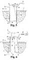
- FIG. 5is a side view of the retractor shown in FIG. 1 inserted through an incision in a patient with the retractor in an unexpanded configuration.
- FIG. 6is the retractor of FIG. 5 in an expanded configuration and with viewing instruments diagrammatically shown.
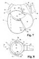
- FIG. 7is a perspective view looking toward the bottom of the expanded retractor of FIG. 3 .
- FIG. 8is a top plan view of the expanded retractor of FIG. 3 .
- FIG. 9is a perspective view of the upper portion of the unexpanded retractor of FIG. 1 .
- FIG. 10is a perspective view of the upper portion of the expanded retractor of FIG. 3 .
- FIG. 11is a perspective view of the upper portion of the unexpanded retractor of FIG. 1 with an expansion instrument positioned adjacent thereto.
- FIG. 12is a perspective view of the retractor of FIG. 3 with the expansion instrument of FIG. 11 positioned therein to move the retractor to its expanded configuration.
- FIGS. 13 a - 13 dcillustrate another embodiment expansion instrument having an adjustable foot.
- FIGS. 14 a - 14 cillustrate another embodiment expandable retractor and a coupling member comprising a portion thereof.
- FIGS. 15 a - 15 cillustrate the proximal end of yet another embodiment expandable retractor.
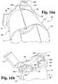
- FIGS. 16 a - 16 billustrate another embodiment expandable retractor.
- the present inventionprovides instruments and methods for performing percutaneous surgery, including spinal surgeries that include one or more techniques such as laminotomy, laminectomy, foramenotomy, facetectomy, discectomy, interbody fusion, spinal nucleus or disc replacement, and implant insertion, for example.
- the surgeryis performed through a working channel or passageway provided by a retractor. Viewing of the surgical site at the working end of the retractor can be accomplished with optics mounted on the retractor, positioned over the retractor, and/or through a viewing system such as lateral fluoroscopy.
- the retractoris expandable in situ to increase the size of the working channel to facilitate access to the working space at the distal end of the retractor while minimizing trauma to tissue surrounding the retractor.
- the retractorcan be used with any surgical approach to the spine, including anterior, posterior, posterior mid-line, lateral, postero-lateral, and/or antero-lateral approaches, and in other regions besides the spine.
- FIGS. 1-2there is illustrated a retractor 20 that includes a first portion 22 coupled to a second portion 42 .
- First portion 22has a distal end 24 and an opposite proximal end 26 .
- Second portion 42has a distal end 44 and an opposite proximal end 46 .
- first portion 22is pivotally coupled to second portion 42 at proximal ends 26 , 46 .
- a working channel 50is formed by first portion 22 and second portion 42 .
- Working channel 50extends between and opens at distal ends 24 , 44 and proximal ends 26 , 46 .
- Retractor 20is movable to an expanded configuration, as shown in FIGS.
- first portion 22 and second portion 42pivoting relative to one another about proximal ends 26 , 46 .
- Other coupling arrangementsare also contemplated that allow first portion and second portion 42 to be moved away from one another to expand retractor 20 and increase the size of working channel 50 between its distal and proximal ends.
- Retractor 20is insertable through skin and tissue of a patient to provide working channel 50 to the surgical site. It is contemplated that retractor 20 is inserted through the skin and tissue in an unexpanded configuration, such as shown in FIGS. 1-2 . After insertion into the patient, retractor 20 is expanded through the skin and tissue to an expanded configuration that increases the size of working channel 50 from proximal ends 26 , 46 to distal ends 24 , 44 .
- First portion 22includes a semi-cylindrical body 23 extending between distal end 24 and proximal end 26 .
- a collar 28extends about proximal end 26 , and forms a lip 28 a extending about the outer surface of body 23 .
- Second portion 42includes a semi-cylindrical body 43 extending between distal end 44 and proximal end 46 .
- a collar 48extends about proximal end 46 of second portion 42 , and defines a lip 48 a extending about the outer surface of body 43 .
- a first coupling member 30 apivotally couples a first side of first portion 22 to second portion 42 at their proximal ends 26 , 46 .
- a second coupling member 30 b opposite first coupling member 30 apivotally couples the other side of first portion 22 to second portion 42 at their proximal ends 26 , 46 along another side of retractor 20 .
- first and second coupling members 30 a , 30 bare pins that extend through aligned holes or passageways provided through collars 28 , 48 to pivotally couple first portion 22 to second portion 42 .
- Other coupling arrangementsare also contemplated at proximal ends 26 , 46 of first and second portions 22 , 42 .
- proximal end 26 of first portion 22may be hingedly attached to proximal end 46 of second portion 42 with one or more hinges at each side of retractor 20 .
- at least the proximal ends of first portion 22 and second portion 42are formed of a single piece of material and a resilient hinge couples first portion 22 to second portion 42 at their proximal ends 26 , 46 .
- Other embodimentscontemplate a slotted arrangement extending around the proximal end of one of the retractor portions and one or more pins from the other retractor portion received in the slotted arrangement.
- Bracket 40extends from and is integrally formed with or attached to collar 48 of second portion 42 . Bracket 40 can also be provided on collar 28 in lieu of or in addition to bracket 40 on collar 48 . Bracket 40 extends away from working channel 50 and is connectable to one end of a flexible or articulatable arm 41 ( FIG. 6 .) The opposite end of arm 41 (not shown) can be mounted on the surgical table or other support device. Arm 41 supports retractor 20 in the patient yet allows percutaneous manipulation and re-positioning of retractor 20 .
- Body 23 of first portion 22extends around at least a portion of body 43 of second portion 42 .
- Body 23has a perimeter length along distal end 24 which is greater than the perimeter length of body 23 at proximal end 26 .
- Body 43 of second portion 42includes a perimeter length along distal end 44 which is the same or can be about the same as the perimeter length of body 43 adjacent proximal end 46 .
- Body 23 of first portion 22can be flexible enough to extend around second portion 42 in form fitting relationship when retractor 20 is the unexpanded configuration of FIGS. 1 and 2 to minimize the profile of retractor 20 .
- Body 23flexes outwardly and rides along the outer surface of body 43 of second portion 42 as first portion 22 and second portion 42 are pivoted relative to one another to the expanded configuration of retractor 20 .
- first portion 22 and second portion 42are each made from surgical grade stainless steel.
- bodies 23 , 43including, for example, plastics and metals and metal alloys, such as, for example, spring steel, shape memory metals and alloys, and aluminum.
- body 23can be provided with a cross-sectional thickness t 1 that provides the desired flexibility, yet is sufficiently rigid to maintain retraction of the skin and tissue.
- Body 43 of second portion 42can be provided with a thickness t 2 that can be the same or greater than thickness t 1 of first portion 22 .
- the reduced thickness of body 23provides it greater flexibility to flex inwardly and outwardly expand around body 43 of second portion 42 .
- Thickness t 2provides second portion 43 greater rigidity to resist bending or bowing under the forces exerted on it by body 23 during and after movement of retractor 20 to its expanded configuration.
- working channel 50has a generally circular cross-section along retractor 20 , as best shown in FIG. 2 .
- Working channel 50has a first width D 1 between the opposite edges of second portion 42 positioned in first portion 22 .
- a second width D 2is defined between the mid-portions of first body 23 and second body 43 in the direction of expansion of first portion 22 relative to second portion 42 .
- first and second widths D 1 and D 2are substantially the same since unexpanded working channel 50 has a generally circular cross-section.
- the portion of the expanded working channel 50 extending along the opposite edges of second body 43maintains first width D 1 .
- first body 23is flexed outwardly relative to second body 43 , and defines a third width D 3 between the sides of first body 23 that is greater than first width D 1 .
- first body 23 and second body 43define a fourth width D 4 in the direction of expansion of first portion 22 relative to second portion 42 that is greater than second width D 2 . It is further contemplated that width D 4 can be greater than widths D 1 and D 3 .
- working channel 50can have a cylindrical shape with, for example, a circular, oval, elliptical, or polygonal cross-section.
- working channel 50can have a frusto-conical shape with, for example a cross-section that is figure-eight or snowman shaped, oval, elliptical, circular or polygonal.
- the size of the cross-section of working channel 50decreases from distal end to the proximal end of retractor 20 .
- first portion 22 and second portion 42are expanded predominantly in one direction to retract muscle and tissue along pathway P.
- retractor 20can be primarily or predominantly expandable in the direction of the spinal column axis. Since the muscle tissue adjacent the spine has a fiber orientation that extends generally in the direction of the spinal column axis, the expansion of retractor 20 separates the muscle tissue along the fibers, thus minimizing their separation and the resultant tearing and trauma to the muscle tissue is minimized.
- working channel 50expands primarily in a direction other than along the spinal column axis or in areas other than spine.
- Embodiments of retractor 20are also contemplated in which working channel 50 is circular or polygonal in cross-section and expands substantially the same amount in all directions.
- FIGS. 5-6positioning of retractor 20 through the skin S and tissue T of the patient will be described.
- An incisionis made in skin S adjacent the location of a patient's anatomy to be accessed.
- the incisioncan be made at a vertebral level at a location that provides access to the disc space between adjacent vertebrae or to one or more vertebra through a desired approach.
- skin S and tissue TPrior to insertion of retractor 20 , skin S and tissue T can be sequentially dilated via guidewires and/or one or more dilators of increasing size to form a pathway P through skin S and tissue T to the surgical site in the patient.
- retractor 20is positioned over the last inserted dilator in pathway P for retractor 20 .
- Working channel 50 through retractor 20provides access to a working space WS at the distal end of retractor 20 when the guidewires and dilators, if used, are removed therefrom.
- Retractor 20can be pivoted from its unexpanded, insertion configuration to an expanded configuration as shown in FIG. 6 .
- first portion 22 and second portion 42are pivoted away from one another about first and second coupling members 30 a , 30 b at proximal ends 26 , 46 .
- pathway P′ through skin S and tissue Tis formed by first portion 22 and second portion 42 .
- the size of working space WScan be increased while minimizing trauma to the tissue and skin along pathway P.
- Working channel 50has a tapered configuration that reduces in size from the distal end of retractor 20 adjacent working space WS through skin S to the proximal end of retractor 20 .
- the tapered working channelprovides the surgeon greater access and increased visualization of working space WS.
- the tapered working channel 50also allows greater angulation of instruments placed through working channel 50 , more selection in positioning of instruments within working channel 50 , and the ability to position instruments adjacent the inner wall surfaces of the expanded first and second portions 22 , 42 , increasing the room available at working space WS for multiple instruments.
- Viewing instrumentscan be positioned in or adjacent to working channel 50 to facilitate surgeon viewing of working space WS and the operative site.
- an endoscopic viewing element 90can be mounted on the proximal end of retractor 20 such that its scope portion 92 extends along working channel 50 .
- a microscopic viewing element 95can also be positioned over the proximal end of retractor 20 for viewing working space WS and the surgical site.
- Other imaging techniquessuch as lateral fluoroscopy, can be used alone or in combination with the endoscopic and microscopic viewing elements. Further examples of such viewing instruments and mounting or orienting the same relative to retractor 20 are provided in U.S.
- retractor 20can be mounted on the proximal end of retractor 20 , such as nerve root retractors, tissue retractors, irrigation and/or aspiration instruments, illumination instruments and the like for use in surgical procedures through retractor 20 in the working space.
- instrumentssuch as nerve root retractors, tissue retractors, irrigation and/or aspiration instruments, illumination instruments and the like for use in surgical procedures through retractor 20 in the working space.
- First body 23 of first portion 22includes a first edge 32 a extending between distal end 24 and proximal end 26 .
- First body 23 of first portion 22includes an opposite second edge 32 b extending between distal end 24 and proximal end 26 .
- Second portion 42includes a first edge 51 a extending along one side of second body 43 and an opposite second edge 51 b extending along the opposite side of second body 43 .
- First edge 51 aincludes a grooved portion 54 a extending from distal end 44 along at least a portion of the length of first edge 51 a .
- An engagement surface 52 aextends along grooved portion 54 a .
- second edge 51 bincludes grooved portion 54 b extending from distal end 44 along at least a portion of the length of second edge 51 b .
- An engagement surface 52 bextends along grooved portion 54 b.
- first edge 51 a of second body 43is adjacent first edge 32 a of first body 23
- second edge 51 b of body 43is adjacent second edge 32 b of first body 23
- First edge 32 aresides at least partially in grooved portion 54 a
- second edge 32 bresides at least partially in grooved portion 52 b
- First edge 32 acontacts engagement surface 52 a along grooved portion 54 a to maintain retractor 20 in its expanded configuration
- second edge 32 bcontacts engagement surface 52 b in grooved portion 54 b to maintain retractor 20 in its expanded configuration.
- the flexible second portion 22tends to return toward its unexpanded configuration, thus first and second edges 32 a , 32 b frictionally engage the engagement surfaces extending along each of the grooved portions 54 a , 54 b .
- first and second portion 22 , 42can be provided with a ridge or protrusion at each of its opposite edges, and first portion 44 can engage the ridge or protrusion.
- working channel 50is not completely enclosed.
- Collar 28includes a recess 33 a formed adjacent first edge 32 a on one side of first portion 22 , and a second recess 33 b opposite first recess 33 a on the other side of first portion 22 .
- Recess 33 aincludes an engagement surface 35 a along an inner side thereof
- second recess 33 bincludes an engagement surface 35 b extending along an inner side thereof.
- a first extension 34 aextends along the outside of first recess 33 a
- a second recess 34 bextends along the outside of second recess 33 b .
- First extension 34 a and second extension 34 bextend beyond the adjacent first edge 32 a and second edge 32 b , respectively, of body 23 of first portion 22 .
- Second portion 42includes a first recess 55 a along one side of second portion 42 , and a second recess 55 b along another side of second portion 42 .
- First recess 55 aincludes an engagement surface 56 a
- second recess 55 bincludes an engagement surface 56 b .
- a first extension 58 aextends along the inner side of first recess 55 a
- a second extension 58 bextends along the inner side of second recess 55 b .
- First extension 58 aincludes an engagement surface 59 a
- second extension 55 balso includes a similarly situated engagement surface.
- First extension 58 aresides within first recess 33 a adjacent first extension 34 a of first portion 22
- second extension 58 bresides within second recess 33 b adjacent second extension 34 b of first portion 22
- First coupling member 30 aincludes a pin extending through passage 31 a of first extension 34 a of first portion 22 and pivotally couples first extension 58 a of second portion 42 thereto
- Second coupling member 30 bincludes a pin extending through passage 31 b of second extension 34 b of first portion 22 and pivotally couples second extension 58 b of second portion 42 thereto.
- retractor 20With retractor 20 in its unexpanded configuration as shown in FIG. 9 , a gap is formed between engagement surfaces 35 a , 35 b of first portion 22 and engagement surfaces 59 a , 59 a of extensions 58 a , 58 b of second portion 42 .
- engagement surfaces 59 a , 59 acontact engagement surfaces 35 a , 35 b of first portion 22 .
- engagement surfaces 37 a , 37 b of extensions 34 a , 34 b of first portion 22contact engagement surfaces 56 a , 56 b of second portion 42 .
- the contact between the engagement surfaces of the recesses and extensionslimit the pivotal movement of first portion 22 relative to second portion 42 .
- First portion 22can include a relieved portion 39 a below first engagement surface 59 a and a similar relief under second engagement surface 35 b .
- the reliefsallow some flexing of engagement surfaces 35 a , 35 b to ensure engagement surfaces 59 a , 59 b of extensions 58 a , 58 b fully seat on engagement surfaces 35 a , 35 b.
- Expansion instrument 60includes a first handle 62 pivotally coupled to a second handle 64 with pin 66 .
- a leaf spring 68can extend between first handle 62 and second handle 64 to bias handles 62 , 64 in a closed position as shown in FIG. 11 .
- Extending distally from the pivotal connection of first handle 62 and second handle 64are first distal portion 70 and second distal portion 72 , respectively.
- Distal portion 70includes a foot 74 at a distal end thereof, and distal portion 72 includes a foot 76 at a distal end thereof.
- Feet 74 , 76extend toward first portion 22 and second portion 42 , respectively when expansion instrument 60 is inserted in working channel 50 of retractor 20 .
- Expansion instrument 60includes a first arm 78 a and a second arm 78 b above pin 66 .
- First arm 78 ais pivotally coupled to first and second handles 62 , 64 via coupler 84 a
- second arm 78 bis pivotally coupled to first and second handles 62 , 64 via coupler 84 b .
- First and second arms 78 a , 78 bextend transversely to the orientation of feet 74 , 76 .
- First arm 78 aincludes an engagement member 80 a having a receptacle 82 a positionable over the head of first coupling member 30 a .
- Second arm 78 bincludes an engagement member 80 b having a receptacle positionable over the head of second coupling member 30 b.
- expansion instrument 60is mountable on retractor 20 by pivoting first arm 78 a so that first coupling member 30 a is captured in receptacle 82 a of engagement member 80 a , and second coupling member 30 b is captured in receptacle 82 b of engagement member 80 b .
- the engagement of expansion instrument 60 to retractor 20ensures that expansion instrument 60 is not inserted too far into working channel 50 before and during insertion, and allows the application a steady and uniform expansion force without expansion instrument 60 slipping relative to retractor 20 .
- expansion instrument 60is rotated 90 degrees so the feet 74 , 76 can apply an expansion force to first portion 22 in the direction of the pivot axis of first portion 22 and second portion 42 .
- the expansion of first portion 22 in this directiondisengages or unlocks edges 32 a , 32 b from engagement surfaces 52 a , 52 b of second portion 42 and allows first portion 22 and second portion 42 to pivot relative to one another to unexpand retractor 20 .
- Retractor 20can then be withdrawn from the tissue in its unexpanded condition, minimizing pressure on the adjacent tissue as retractor 20 is withdrawn.
- expansion instrument 60 ′can be similar to expansion instrument 60 discussed above, and like elements between expansion instruments 60 and 60 ′ are designated with the same reference numeral.
- Expansion instrument 60 ′includes a movable foot 74 ′ coupled to distal portion 70 ′.
- foot 74 ′is rotatable about pin 75 ′ relative to distal portion 70 ′ in order to position selected ones of the retractor portion contact surfaces 74 a′ , 74 b′ or 74 c′ adjacent one of the retractor portions 22 , 42 .
- the contact surfaces 74 a′ , 74 b′ and 74 c′are located at differing distances from pin 75 ′ to allow the surgeon to select the desired amount of expansion for retractor 20 .
- Foot 74 ′is rotated about pin 75 ′ to select the desired contact surface by orienting the desired contact surface away from contact surface 76 a of foot 76 .
- contact surface 74 a ′is selected to provide minimum expansion since it is located closest to pin 75 ′.
- contact surface 74 b ′is selected to provide maximum expansion since it is located furthest away from pin 75 ′.
- FIG. 13 bcontact surface 74 b ′ is selected to provide maximum expansion since it is located furthest away from pin 75 ′.
- FIG. 13 c contact surface 74 c ′is selected to provide intermediate expansion since it has a distance from pin 75 ′ that is between the distances of contact surface 74 a ′ and contact surface 74 b ′.
- FIG. 13 dshows expansion instrument 60 ′ mounted on retractor 20 with contact surface 74 c ′ of foot 74 in contact with second portion 42 and contact surface 76 a of foot 76 in contact with first portion 22 of retractor 20 .
- each of the contact surfaces 74 a ′, 74 b ′ and 74 c ′can correspond to a particular retractor length.
- the depth which expansion instrument 60 ′ extends into the retractoris the same no matter the length of the retractor.
- the first and second portions of a shorter retractorwill be separated a greater amount at the depth of feet 74 ′, 76 than will a longer retractor.
- contact surface 74 a ′can be selected for a longer length retractor
- contact surface 74 b ′can be selected for a shorter length retractor
- contact surface 74 c ′can be selected for an intermediate length retractor.
- expansion instruments 60 , 60 ′can be oriented so that feet 74 , 74 ′ contact first portion 22 and foot 76 contacts second portion 42 . It is further contemplated that expansion instruments 60 , 60 ′ can be provided so that they are not mountable on the retractor, but rather are held in position at the desired depth in the retractor for expansion of the retractor.
- retractor 20can be provided in a kit with lengths ranging from 20 millimeters to 100 millimeters in increments of 10 or 20 millimeters. It is further contemplated that retractor 20 can be provided in a kit with various diameters, such as 14, 16, 18, 20, 21 or 25 millimeters in its unexpanded configuration. It should be understood, however, that the present invention contemplates that retractor 20 can have other lengths and diameters and can be provided in a kit with different increments. The appropriate length for retractor 20 will depend on the depth of the desired surgical location below the skin S of the patient, the anatomical location of the surgery, and the patient's anatomy. These factors in retractor selection can be evaluated through pre-operative planning prior to surgery by x-rays or other known imaging technique, and can be adjusted during the surgical procedure if necessary since retractors of differing lengths and diameters can be made available.
- FIGS. 14 a - 14 bthere is shown another embodiment expandable retractor 220 .
- retractor 220is in its unexpanded configuration and in FIG. 14 b retractor 220 is in its expanded configuration.
- Retractor 220is similar in many respects to retractor 20 discussed above.
- Retractor 220includes a first portion 222 having a distal end 224 , a proximal end 226 , and a collar 228 at proximal end 226 .
- Retractor 220further includes a second portion 242 having a distal end 244 , a proximal end 246 , and a collar 248 at proximal end 246 .
- First coupling member 230 a and second coupling member 230 bpivotally couple first portion 222 to second portion 242 .
- a first lever arm 232 ais connected with and extends from first coupling member 230 a around collar 248
- a second lever arm 232 bis connected with and extends from second coupling member 230 b around collar 248 .
- lever arms 232 a , 232 bare adjacent collar 248 , and coupling members 230 a , 230 b project outwardly from collar 228 as shown in FIG. 14 a .
- Coupling members 230 a , 230 bas shown in FIG. 13 c , have a first keyed portion 237 configured to engage slotted hole 234 of collar 248 .
- the cylindrical portions 239 of coupling members 230 a , 230 brotatably reside in the slotted hole (not shown) extending through collar 228 of first portion 222 . This allows first portion 222 to be pivoted relative to second portion 242 about coupling members 230 a , 230 b.
- first portion 222When first portion 222 is pivoted relative to second portion 242 to the expanded configuration, the slotted portions of slotted hole 234 and the slotted hole through collar 228 are aligned.
- Coupling members 230 a , 230 bcan be pressed inwardly so that a second keyed portion 235 of coupling members 230 a , 230 b engages the slotted hole formed through collar 228 , while the first keyed portion 237 remains engaged in slotted hole 234 of collar 248 , thus fixing first portion 222 relative to second portion 242 .
- Lever arms 232 a , 232 bextend away from collar 248 when first portion 222 is locked relative to second portion 242 .
- lever arms 232 a , 232 bare pressed toward collar 248 to move coupling members 230 a , 230 b and their second keyed portions 235 out of engagement with the slotted holes in collar 228 of first portion 222 .
- First portion 222can then pivot toward second portion 242 to collapse retractor 220 for withdrawal from the patient.
- FIGS. 15 a - 15 canother embodiment expandable retractor 120 is shown with a ratchet and pawl type mechanism at the proximal ends of first portion 122 and second portion 142 .
- the ratchet and pawl mechanismmaintains retractor 120 in its expanded configuration.
- the provision of a grooved portion and engagement surfaceis not precluded.
- First portion 122includes a collar 128 at its proximal end.
- Collar 128includes an extension 134 extending from each side thereof, it being understood that only one side is shown in FIGS. 15 a - 15 c .
- second portion 142includes an extension 158 extending from each side thereof that is positionable alongside extension 134 of first portion 122 , it being understood that only one side is shown in FIGS. 15 a - 15 c .
- a pin 130pivotally couples extensions 134 , 158 to one another.
- Extension 134includes a number of teeth 137 formed at the end thereof that are engageable with ends 156 of pawls 157 extending around collar 148 . Pawls 157 are biased into engagement with teeth 137 and moveable relative to collar 148 for disengagement of ends 156 with teeth 137 .
- retractor 120When in the unexpanded configuration (not shown) teeth 156 are not engaged by any of the pawls 157 .
- retractor 120is expanded by pivoting first portion 122 in the direction of arrow R relative to second portion 142 so that lower pawl 157 is biased into engagement with lower tooth 137 .
- first portion 122is further pivoted in the direction of arrow R relative to second portion 142 to expand retractor 120 with the end 156 of middle pawl 157 in engagement with the middle tooth 137 .
- FIG. 15 aretractor 120 is expanded by pivoting first portion 122 in the direction of arrow R relative to second portion 142 so that lower pawl 157 is biased into engagement with lower tooth 137 .
- first portion 122is further pivoted in the direction of arrow R relative to second portion 142 to expand retractor 120 with the end 156 of middle pawl 157 in engagement with the middle tooth 137 .
- first portion 122is further pivoted in the direction of arrow R relative to second portion 142 to expand retractor 120 with the end 156 of upper pawl 157 in engagement with the upper tooth 137 .
- teeth 137 and pawls 157can be spaced so that retractor 120 is expanded incrementally.
- the teeth 136 and pawls 157are spaced so that first portion 122 is pivoted in 5 degree increments relative to second portion 142 , ranging from 0 degrees to 15 degrees. Other increments are also contemplated.
- FIGS. 16 a - 16 billustrate another embodiment retractor 320 that is similar to retractor 20 but includes another proximal end configuration.
- retractor 320is in its unexpanded configuration and in FIG. 16 a retractor 320 is in its expanded configuration.
- Retractor 320includes a first portion 322 having a distal end 324 , a proximal end 326 , and a collar 328 at proximal end 326 .
- Retractor 320further includes a second portion 342 having a distal end 344 , a proximal end 346 , and a collar 348 at proximal end 346 .
- First coupling member 330 a and second coupling member 330 bpivotally couple first portion 322 to second portion 342 about a pivot axis A.
- Collars 328 , 348have a height that is less than the height of collars 28 , 48 of retractor 20 , reducing the retractor length. Viewing instruments and other instruments can be positioned in, over, and/or attached to retractor 320 as discussed above with respect to retractor 20 .
- Collar 328includes a first extension 334 a extending along one side thereof and above collar 328 , and a second extensions 334 b extending along the other side thereof and above collar 328 .
- First extension 334 a and second extension 334 bare offset laterally with respect to collar 328 to form recesses for receiving respective ones of the extensions 358 a , 358 b of collar 348 therealong so that extensions 358 a , 358 b do not protrude into the working channel of retractor 320 .
- Extensions 358 a , 358 bextend above collar 348 .
- Pivot axis Ais thus offset proximally from the proximal ends of collars 328 , 348 so that first portion 322 and second portion 342 are expandable through their respective proximal ends to coupling members 330 a , 330 b.
- Collar 328includes a first contact surface 335 a below first extension 358 a of collar 348 , and a second contact surface 335 b below second extension 358 b of collar 348 .
- Collar 348includes a first lateral extension 356 a that provides a contact surface below first extension 334 a of collar 328 , and an opposite second lateral extension that provides a contact surface below second extension 334 b of collar 328 .
- extensions 334 a , 334 bengage respective ones of the contact surfaces of collar 348
- extensions 358 a , 358 bengage respective ones of the contact surfaces of collar 328 , preventing over-expansion of retractor 320 .
- first and second portions of the retractorare not provided with proximal end collars.
- first and second portionsare not pivotally coupled to one another, but rather to intermediate members extending between the first and second portions along each side of the retractor.
Landscapes
- Health & Medical Sciences (AREA)
- Life Sciences & Earth Sciences (AREA)
- Surgery (AREA)
- Molecular Biology (AREA)
- General Health & Medical Sciences (AREA)
- Biomedical Technology (AREA)
- Heart & Thoracic Surgery (AREA)
- Medical Informatics (AREA)
- Nuclear Medicine, Radiotherapy & Molecular Imaging (AREA)
- Animal Behavior & Ethology (AREA)
- Engineering & Computer Science (AREA)
- Public Health (AREA)
- Veterinary Medicine (AREA)
- Pathology (AREA)
- Physics & Mathematics (AREA)
- Biophysics (AREA)
- Optics & Photonics (AREA)
- Radiology & Medical Imaging (AREA)
- Surgical Instruments (AREA)
Abstract
Description
Claims (71)
Priority Applications (17)
| Application Number | Priority Date | Filing Date | Title |
|---|---|---|---|
| US10/117,440US7261688B2 (en) | 2002-04-05 | 2002-04-05 | Devices and methods for percutaneous tissue retraction and surgery |
| CA002481180ACA2481180A1 (en) | 2002-04-05 | 2003-04-02 | Devices and methods for tissue retraction |
| EP10180674.3AEP2258276A3 (en) | 2002-04-05 | 2003-04-02 | Devices for percutaneous tissue retraction |
| AT03746580TATE408376T1 (en) | 2002-04-05 | 2003-04-02 | DEVICES AND METHODS FOR RETRACTION OF TISSUE |
| AU2003262144AAU2003262144B2 (en) | 2002-04-05 | 2003-04-02 | Devices and methods for tissue retraction |
| DE60323617TDE60323617D1 (en) | 2002-04-05 | 2003-04-02 | DEVICES AND METHOD FOR RETRACTION OF TISSUE |
| EP08164466.8AEP1994889B1 (en) | 2002-04-05 | 2003-04-02 | Devices for percutaneous tissue retraction |
| KR1020047015882AKR101190948B1 (en) | 2002-04-05 | 2003-04-02 | Devices and methods for percutaneous tissue retraction and surgery |
| CNB038131242ACN100396245C (en) | 2002-04-05 | 2003-04-02 | Percutaneous tissue retraction and surgical equipment |
| EP03746580AEP1494592B1 (en) | 2002-04-05 | 2003-04-02 | Devices and methods for tissue retraction |
| JP2003583230AJP4336204B2 (en) | 2002-04-05 | 2003-04-02 | Retractor for percutaneous surgery |
| PCT/US2003/010090WO2003086202A2 (en) | 2002-04-05 | 2003-04-02 | Devices and methods for tissue retraction |
| US11/639,517US7988624B2 (en) | 2002-04-05 | 2006-12-14 | Devices and methods for percutaneous tissue retraction and surgery |
| US11/881,101US7981030B2 (en) | 2002-04-05 | 2007-07-25 | Devices and methods for percutaneous tissue retraction and surgery |
| US14/744,745USRE46148E1 (en) | 2002-04-05 | 2015-06-19 | Devices and methods for percutaneous tissue retraction and surgery |
| US14/744,710USRE46403E1 (en) | 2002-04-05 | 2015-06-19 | Devices and methods for percutaneous tissue retraction and surgery |
| US14/744,770USRE46134E1 (en) | 2002-04-05 | 2015-06-19 | Devices and methods for percutaneous tissue retraction and surgery |
Applications Claiming Priority (1)
| Application Number | Priority Date | Filing Date | Title |
|---|---|---|---|
| US10/117,440US7261688B2 (en) | 2002-04-05 | 2002-04-05 | Devices and methods for percutaneous tissue retraction and surgery |
Related Child Applications (4)
| Application Number | Title | Priority Date | Filing Date |
|---|---|---|---|
| US11/639,517DivisionUS7988624B2 (en) | 2002-04-05 | 2006-12-14 | Devices and methods for percutaneous tissue retraction and surgery |
| US11/639,517ContinuationUS7988624B2 (en) | 2002-04-05 | 2006-12-14 | Devices and methods for percutaneous tissue retraction and surgery |
| US11/881,101DivisionUS7981030B2 (en) | 2002-04-05 | 2007-07-25 | Devices and methods for percutaneous tissue retraction and surgery |
| US14/744,710ReissueUSRE46403E1 (en) | 2002-04-05 | 2015-06-19 | Devices and methods for percutaneous tissue retraction and surgery |
Publications (2)
| Publication Number | Publication Date |
|---|---|
| US20030191371A1 US20030191371A1 (en) | 2003-10-09 |
| US7261688B2true US7261688B2 (en) | 2007-08-28 |
Family
ID=28674201
Family Applications (6)
| Application Number | Title | Priority Date | Filing Date |
|---|---|---|---|
| US10/117,440CeasedUS7261688B2 (en) | 2002-04-05 | 2002-04-05 | Devices and methods for percutaneous tissue retraction and surgery |
| US11/639,517CeasedUS7988624B2 (en) | 2002-04-05 | 2006-12-14 | Devices and methods for percutaneous tissue retraction and surgery |
| US11/881,101CeasedUS7981030B2 (en) | 2002-04-05 | 2007-07-25 | Devices and methods for percutaneous tissue retraction and surgery |
| US14/744,710Expired - LifetimeUSRE46403E1 (en) | 2002-04-05 | 2015-06-19 | Devices and methods for percutaneous tissue retraction and surgery |
| US14/744,770Expired - Fee RelatedUSRE46134E1 (en) | 2002-04-05 | 2015-06-19 | Devices and methods for percutaneous tissue retraction and surgery |
| US14/744,745Expired - Fee RelatedUSRE46148E1 (en) | 2002-04-05 | 2015-06-19 | Devices and methods for percutaneous tissue retraction and surgery |
Family Applications After (5)
| Application Number | Title | Priority Date | Filing Date |
|---|---|---|---|
| US11/639,517CeasedUS7988624B2 (en) | 2002-04-05 | 2006-12-14 | Devices and methods for percutaneous tissue retraction and surgery |
| US11/881,101CeasedUS7981030B2 (en) | 2002-04-05 | 2007-07-25 | Devices and methods for percutaneous tissue retraction and surgery |
| US14/744,710Expired - LifetimeUSRE46403E1 (en) | 2002-04-05 | 2015-06-19 | Devices and methods for percutaneous tissue retraction and surgery |
| US14/744,770Expired - Fee RelatedUSRE46134E1 (en) | 2002-04-05 | 2015-06-19 | Devices and methods for percutaneous tissue retraction and surgery |
| US14/744,745Expired - Fee RelatedUSRE46148E1 (en) | 2002-04-05 | 2015-06-19 | Devices and methods for percutaneous tissue retraction and surgery |
Country Status (10)
| Country | Link |
|---|---|
| US (6) | US7261688B2 (en) |
| EP (3) | EP1994889B1 (en) |
| JP (1) | JP4336204B2 (en) |
| KR (1) | KR101190948B1 (en) |
| CN (1) | CN100396245C (en) |
| AT (1) | ATE408376T1 (en) |
| AU (1) | AU2003262144B2 (en) |
| CA (1) | CA2481180A1 (en) |
| DE (1) | DE60323617D1 (en) |
| WO (1) | WO2003086202A2 (en) |
Cited By (110)
| Publication number | Priority date | Publication date | Assignee | Title |
|---|---|---|---|---|
| US20040116777A1 (en)* | 2002-12-13 | 2004-06-17 | Jeffrey Larson | Guided retractor and methods of use |
| US20050159757A1 (en)* | 2002-06-24 | 2005-07-21 | Endius Incorporated | Surgical instrument for moving vertebrae |
| US20070016220A1 (en)* | 2001-03-01 | 2007-01-18 | Sdgi Holding, Inc. | Method for using dynamic lordotic guard |
| US20070027364A1 (en)* | 2005-07-28 | 2007-02-01 | Stefan Schwer | Expandable access device |
| US20070032703A1 (en)* | 2005-07-11 | 2007-02-08 | Sankaran Meera L | Radially expansive surgical instruments for tissue retraction and methods for using the same |
| US20070118023A1 (en)* | 2002-04-05 | 2007-05-24 | Smith Maurice M | Devices and methods for percutaneous tissue retraction and surgery |
| US20070142857A1 (en)* | 2001-05-15 | 2007-06-21 | Dipoto Gene P | Structure for receiving surgical instruments |
| US20070208227A1 (en)* | 2002-07-11 | 2007-09-06 | Nuvasive, Inc. | Surgical access system and related methods |
| US20070213739A1 (en)* | 2001-03-01 | 2007-09-13 | Sdgi Holdings, Inc. | Method for using dynamic lordotic guard with movable extensions for creating an implantation space posteriorly in the lumbar spine |
| US20070288026A1 (en)* | 2006-06-09 | 2007-12-13 | Endius, Inc. | Methods and apparatus for access to and/or treatment of the spine |
| US20080114209A1 (en)* | 2006-11-09 | 2008-05-15 | Cohen Dan S | Surgical retractor device and related methods |
| US20080249372A1 (en)* | 2007-03-30 | 2008-10-09 | Joey Camia Reglos | Retractor |
| US20090018399A1 (en)* | 2004-10-08 | 2009-01-15 | Scot Martinelli | Surgical access system and related methods |
| US20090156902A1 (en)* | 2002-06-26 | 2009-06-18 | Jonathan Dewey | Instruments and methods for minimally invasive tissue retraction and surgery |
| US20090203967A1 (en)* | 2002-06-26 | 2009-08-13 | Branch Charles L | Instruments and methods for minimally invasive tissue retraction and surgery |
| US7691120B2 (en)* | 2003-08-26 | 2010-04-06 | Zimmer Spine, Inc. | Access systems and methods for minimally invasive surgery |
| US7691057B2 (en) | 2003-01-16 | 2010-04-06 | Nuvasive, Inc. | Surgical access system and related methods |
| US7758501B2 (en) | 2006-01-04 | 2010-07-20 | Depuy Spine, Inc. | Surgical reactors and methods of minimally invasive surgery |
| US20100217090A1 (en)* | 2009-02-26 | 2010-08-26 | Heiges Bradley A | Retractor and mounting pad |
| US20100217088A1 (en)* | 2009-02-26 | 2010-08-26 | Heiges Bradley A | Surgical dilator, retractor and mounting pad |
| DE102009014527A1 (en)* | 2009-03-13 | 2010-09-16 | Karl Storz Gmbh & Co. Kg | Device for splaying access instrument for minimal invasive engagement during laparoscopic surgery, has splaying element movable in one direction, where distal partial body sections laterally splay during movement of splaying element |
| US20100240961A1 (en)* | 2009-03-23 | 2010-09-23 | International Spinal Innovations, Llc | Minimally invasive surgical retractor with an expanded field of vision |
| US7819801B2 (en) | 2003-02-27 | 2010-10-26 | Nuvasive, Inc. | Surgical access system and related methods |
| US20110034777A1 (en)* | 2009-04-13 | 2011-02-10 | Lanx, Inc. | Expandable retractor and methods incorporating the same |
| US7905840B2 (en) | 2003-10-17 | 2011-03-15 | Nuvasive, Inc. | Surgical access system and related methods |
| US7918792B2 (en) | 2006-01-04 | 2011-04-05 | Depuy Spine, Inc. | Surgical retractor for use with minimally invasive spinal stabilization systems and methods of minimally invasive surgery |
| US7935051B2 (en) | 2002-06-26 | 2011-05-03 | Nuvasive, Inc. | Surgical access system and related methods |
| US7955257B2 (en) | 2006-01-05 | 2011-06-07 | Depuy Spine, Inc. | Non-rigid surgical retractor |
| US7962191B2 (en) | 1998-12-23 | 2011-06-14 | Nuvasive, Inc. | Nerve surveillance cannulae systems |
| US7981031B2 (en) | 2006-01-04 | 2011-07-19 | Depuy Spine, Inc. | Surgical access devices and methods of minimally invasive surgery |
| US20110201893A1 (en)* | 2010-02-12 | 2011-08-18 | O'prey Cormac | Expandable thoracic access port |
| US8016767B2 (en) | 2003-09-25 | 2011-09-13 | Nuvasive, Inc. | Surgical access system and related methods |
| US8025640B2 (en) | 2008-06-27 | 2011-09-27 | Tyco Healthcare Group Lp | Pressurized surgical valve |
| US8038611B2 (en) | 2003-12-18 | 2011-10-18 | Depuy Spine, Inc. | Surgical methods and surgical kits |
| US8062217B2 (en) | 2007-01-26 | 2011-11-22 | Theken Spine, Llc | Surgical retractor with removable blades and method of use |
| US8096996B2 (en) | 2007-03-20 | 2012-01-17 | Exactech, Inc. | Rod reducer |
| US8137284B2 (en) | 2002-10-08 | 2012-03-20 | Nuvasive, Inc. | Surgical access system and related methods |
| US8202304B2 (en) | 2002-08-21 | 2012-06-19 | Theken Spine, Llc | Methods and systems for performing spinal surgery |
| US8226690B2 (en) | 2005-07-22 | 2012-07-24 | The Board Of Trustees Of The Leland Stanford Junior University | Systems and methods for stabilization of bone structures |
| US20120215229A1 (en)* | 2007-02-09 | 2012-08-23 | Alphatec Spine, Inc. | Curvilinear spinal access method and device |
| US8265744B2 (en) | 2001-09-25 | 2012-09-11 | Nuvasive, Inc. | Systems and methods for performing surgical procedures and assessments |
| US8267969B2 (en) | 2004-10-20 | 2012-09-18 | Exactech, Inc. | Screw systems and methods for use in stabilization of bone structures |
| US20120259177A1 (en)* | 2011-04-05 | 2012-10-11 | Warsaw Orthopedic, Inc. | Overlapping Retractor Blade Assemblies |
| US8287597B1 (en) | 2009-04-16 | 2012-10-16 | Nuvasive, Inc. | Method and apparatus for performing spine surgery |
| US8313430B1 (en) | 2006-01-11 | 2012-11-20 | Nuvasive, Inc. | Surgical access system and related methods |
| US8328851B2 (en) | 2005-07-28 | 2012-12-11 | Nuvasive, Inc. | Total disc replacement system and related methods |
| US8523767B2 (en) | 2011-06-16 | 2013-09-03 | Warsaw Orthopedic, Inc. | Add-on retractor element for retractor system |
| US8523865B2 (en) | 2005-07-22 | 2013-09-03 | Exactech, Inc. | Tissue splitter |
| US8574155B2 (en) | 2010-02-12 | 2013-11-05 | Covidien Lp | Expandable surgical access port |
| US8579810B2 (en) | 2010-02-12 | 2013-11-12 | Covidien Lp | Expandable thoracic access port |
| US8597180B2 (en) | 2010-08-12 | 2013-12-03 | Covidien Lp | Expandable thoracic access port |
| US8634904B2 (en) | 2001-07-11 | 2014-01-21 | Nuvasive, Inc. | System and methods for determining nerve proximity, direction, and pathology during surgery |
| US20140142394A1 (en)* | 2012-11-20 | 2014-05-22 | Oguz I. Cataltepe | Flexible surgical sheath and multi-part insertion cannula |
| US8777849B2 (en) | 2010-02-12 | 2014-07-15 | Covidien Lp | Expandable thoracic access port |
| US8790406B1 (en) | 2011-04-01 | 2014-07-29 | William D. Smith | Systems and methods for performing spine surgery |
| US8864658B2 (en) | 2010-08-12 | 2014-10-21 | Covidien Lp | Expandable surgical access port |
| US8888813B2 (en) | 2008-10-20 | 2014-11-18 | Spine View, Inc. | Retractor cannula system for accessing and visualizing spine and related methods |
| US8956284B2 (en) | 2011-01-20 | 2015-02-17 | K2M, Inc. | Minimally invasive retractor and posted screw |
| US8961408B2 (en) | 2010-08-12 | 2015-02-24 | Covidien Lp | Expandable surgical access port |
| US8961409B2 (en) | 2011-12-07 | 2015-02-24 | Covidien Lp | Thoracic access assembly |
| US9039610B2 (en) | 2011-05-19 | 2015-05-26 | Covidien Lp | Thoracic access port |
| US9072501B2 (en) | 2013-03-15 | 2015-07-07 | Regents Of The University Of Minnesota | Micro-orifice surgical access system |
| US9084591B2 (en) | 2012-10-23 | 2015-07-21 | Neurostructures, Inc. | Retractor |
| US9119665B2 (en) | 2011-03-21 | 2015-09-01 | Covidien Lp | Thoracic access port including foldable anchor |
| US9155503B2 (en) | 2010-10-27 | 2015-10-13 | Cadwell Labs | Apparatus, system, and method for mapping the location of a nerve |
| US9198765B1 (en) | 2011-10-31 | 2015-12-01 | Nuvasive, Inc. | Expandable spinal fusion implants and related methods |
| US9211140B2 (en) | 2010-11-24 | 2015-12-15 | Kyphon Sarl | Dynamically expandable cannulae and systems and methods for performing percutaneous surgical procedures employing same |
| US9247955B2 (en) | 2010-08-12 | 2016-02-02 | Covidien Lp | Thoracic access port |
| US20160051136A1 (en)* | 2014-08-19 | 2016-02-25 | Kyphon Sarl | Retracting cannula with illumination and methods of use |
| US9295401B2 (en) | 2012-11-27 | 2016-03-29 | Cadwell Laboratories, Inc. | Neuromonitoring systems and methods |
| US9351845B1 (en) | 2009-04-16 | 2016-05-31 | Nuvasive, Inc. | Method and apparatus for performing spine surgery |
| US9451940B2 (en) | 2008-12-26 | 2016-09-27 | Pantheon Spinal, Llc | Method of retroperitoneal lateral insertion of spinal implants |
| US20170007809A1 (en)* | 2015-07-10 | 2017-01-12 | Coloplast A/S | Dilator and method for penile prosthetic implantation |
| US9554789B2 (en) | 2013-04-17 | 2017-01-31 | DePuy Synthes Products, Inc. | Expandable dilator |
| WO2017040275A1 (en) | 2015-08-28 | 2017-03-09 | Bhdl Holdings, Llc | Surgical dilator, retractor and mounting pad |
| US9675334B2 (en) | 2009-02-26 | 2017-06-13 | Bhdl Holdings, Llc | Surgical dilator, retractor and mounting pad |
| US9743853B2 (en) | 1999-11-24 | 2017-08-29 | Nuvasive, Inc. | Electromyography system |
| US9795771B2 (en) | 2010-10-19 | 2017-10-24 | Warsaw Orthopedic, Inc. | Expandable spinal access instruments and methods of use |
| US9848864B2 (en) | 2014-05-27 | 2017-12-26 | Kyphon SÀRL | Adjustable cannula and methods of use |
| US9918709B2 (en) | 2005-12-07 | 2018-03-20 | Spinal Usa, Inc. | Stand-alone access system for minimally invasive spinal surgery |
| US10098585B2 (en) | 2013-03-15 | 2018-10-16 | Cadwell Laboratories, Inc. | Neuromonitoring systems and methods |
| WO2018231830A1 (en) | 2017-06-12 | 2018-12-20 | Bhdl Holdings, Llc | Surgical dilator, retractor and mounting pad |
| US10258228B2 (en) | 2014-08-08 | 2019-04-16 | K2M, Inc. | Retraction devices, systems, and methods for minimally invasive spinal surgery |
| US10278686B2 (en) | 2010-09-20 | 2019-05-07 | DePuy Synthes Products, Inc. | Spinal access retractor |
| US10413287B2 (en) | 2009-02-26 | 2019-09-17 | Bhdl Holdings, Llc | Surgical dilator, retractor and mounting pad |
| US10433793B1 (en) | 2015-03-27 | 2019-10-08 | Cadwell Laboratories, Inc. | Methods and systems for simultaneous review of brain activity and physical manifestations of users |
| US10687797B2 (en) | 2008-12-18 | 2020-06-23 | Howmedica Osteonics Corp. | Lateral access system for the lumbar spine |
| US10716553B2 (en) | 2017-04-19 | 2020-07-21 | Pantheon Spinal, Llc | Spine surgery retractor system and related methods |
| US10987128B2 (en) | 2017-03-22 | 2021-04-27 | Covidien Lp | Cannula assembly |
| US11128076B2 (en) | 2019-01-21 | 2021-09-21 | Cadwell Laboratories, Inc. | Connector receptacle |
| US11141191B2 (en) | 2020-01-15 | 2021-10-12 | Covidien Lp | Surgical access assembly |
| US11166709B2 (en) | 2016-08-23 | 2021-11-09 | Stryker European Operations Holdings Llc | Instrumentation and methods for the implantation of spinal implants |
| US11177610B2 (en) | 2017-01-23 | 2021-11-16 | Cadwell Laboratories, ino. | Neuromonitoring connection system |
| US11185684B2 (en) | 2018-09-18 | 2021-11-30 | Cadwell Laboratories, Inc. | Minimally invasive two-dimensional grid electrode |
| US11191532B2 (en) | 2018-03-30 | 2021-12-07 | Stryker European Operations Holdings Llc | Lateral access retractor and core insertion |
| US11253182B2 (en) | 2018-05-04 | 2022-02-22 | Cadwell Laboratories, Inc. | Apparatus and method for polyphasic multi-output constant-current and constant-voltage neurophysiological stimulation |
| US11317841B2 (en) | 2018-11-14 | 2022-05-03 | Cadwell Laboratories, Inc. | Method and system for electrode verification |
| US11413029B2 (en) | 2018-10-24 | 2022-08-16 | Stryker European Operations Holdings Llc | Anterior to psoas instrumentation |
| US11443649B2 (en) | 2018-06-29 | 2022-09-13 | Cadwell Laboratories, Inc. | Neurophysiological monitoring training simulator |
| US11471087B2 (en) | 2018-11-09 | 2022-10-18 | Cadwell Laboratories, Inc. | Integrity verification system for testing high channel count neuromonitoring recording equipment |
| US11517239B2 (en) | 2018-04-05 | 2022-12-06 | Cadwell Laboratories, Inc. | Systems and methods for processing and displaying electromyographic signals |
| US11517245B2 (en) | 2018-10-30 | 2022-12-06 | Cadwell Laboratories, Inc. | Method and system for data synchronization |
| US11529107B2 (en) | 2018-11-27 | 2022-12-20 | Cadwell Laboratories, Inc. | Methods for automatic generation of EEG montages |
| US11564674B2 (en) | 2019-11-27 | 2023-01-31 | K2M, Inc. | Lateral access system and method of use |
| US11596337B2 (en) | 2018-04-24 | 2023-03-07 | Cadwell Laboratories, Inc | Methods and systems for operating an intraoperative neurophysiological monitoring system in conjunction with electrocautery procedures |
| US11793504B2 (en) | 2011-08-19 | 2023-10-24 | Nuvasive, Inc. | Surgical retractor system and methods of use |
| US11832847B2 (en) | 2017-08-17 | 2023-12-05 | Stryker European Operations Holdings Llc | Expanders for rod retraction |
| US11950972B2 (en) | 2016-12-12 | 2024-04-09 | Cadwell Laboratories, Inc. | Controller, adapter and connector systems for high density electrode management |
| US11992339B2 (en) | 2018-05-04 | 2024-05-28 | Cadwell Laboratories, Inc. | Systems and methods for dynamic neurophysiological stimulation |
| US12251130B2 (en) | 2021-05-03 | 2025-03-18 | Covidien Lp | Surgical access device having a balloon and methods for manufacturing the same |
Families Citing this family (145)
| Publication number | Priority date | Publication date | Assignee | Title |
|---|---|---|---|---|
| US7682370B2 (en)* | 1998-08-20 | 2010-03-23 | Zimmer Spine, Inc. | Surgical tool for use in expanding a cannula |
| US6187000B1 (en) | 1998-08-20 | 2001-02-13 | Endius Incorporated | Cannula for receiving surgical instruments |
| US7641670B2 (en) | 1998-08-20 | 2010-01-05 | Zimmer Spine, Inc. | Cannula for receiving surgical instruments |
| US7799036B2 (en)* | 1998-08-20 | 2010-09-21 | Zimmer Spine, Inc. | Method and apparatus for securing vertebrae |
| US7985247B2 (en) | 2000-08-01 | 2011-07-26 | Zimmer Spine, Inc. | Methods and apparatuses for treating the spine through an access device |
| US7056321B2 (en) | 2000-08-01 | 2006-06-06 | Endius, Incorporated | Method of securing vertebrae |
| JP3913506B2 (en)* | 2001-09-26 | 2007-05-09 | 三洋電機株式会社 | Disc recording or playback device with a tray that can be moved up and down |
| WO2003057051A1 (en)* | 2002-01-09 | 2003-07-17 | Synthes Ag Chur | Device for drilling or for inserting implants |
| EP2343032B1 (en) | 2002-06-05 | 2012-05-09 | Applied Medical Resources Corporation | Wound retractor |
| US6648888B1 (en)* | 2002-09-06 | 2003-11-18 | Endius Incorporated | Surgical instrument for moving a vertebra |
| US7850608B2 (en) | 2002-10-25 | 2010-12-14 | K2M, Inc. | Minimal incision maximal access MIS spine instrumentation and method |
| WO2004039235A2 (en)* | 2002-10-25 | 2004-05-13 | Endius Incorporated | Apparatus and methods for shielding body structures during surgery |
| US7935054B2 (en)* | 2002-10-25 | 2011-05-03 | K2M, Inc. | Minimal access lumbar diskectomy instrumentation and method |
| US7887482B2 (en)* | 2002-10-25 | 2011-02-15 | K2M, Inc. | Minimal access lumbar diskectomy instrumentation and method |
| US6849064B2 (en)* | 2002-10-25 | 2005-02-01 | James S. Hamada | Minimal access lumbar diskectomy instrumentation and method |
| US7946982B2 (en)* | 2002-10-25 | 2011-05-24 | K2M, Inc. | Minimal incision maximal access MIS spine instrumentation and method |
| US7014608B2 (en)* | 2002-12-13 | 2006-03-21 | Synthes Spine Company, Lp | Guided retractor and methods of use |
| US20060155170A1 (en)* | 2002-12-13 | 2006-07-13 | Synthes Spine Company, Lp | Guided retractor and methods of use |
| US7645232B2 (en) | 2003-05-16 | 2010-01-12 | Zimmer Spine, Inc. | Access device for minimally invasive surgery |
| US7481766B2 (en) | 2003-08-14 | 2009-01-27 | Synthes (U.S.A.) | Multiple-blade retractor |
| US7226451B2 (en)* | 2003-08-26 | 2007-06-05 | Shluzas Alan E | Minimally invasive access device and method |
| US7182729B2 (en)* | 2003-09-18 | 2007-02-27 | Stryker Spine | Surgical retractor with removable scissor arms |
| US7763052B2 (en)* | 2003-12-05 | 2010-07-27 | N Spine, Inc. | Method and apparatus for flexible fixation of a spine |
| US8979900B2 (en) | 2003-09-24 | 2015-03-17 | DePuy Synthes Products, LLC | Spinal stabilization device |
| US7137985B2 (en)* | 2003-09-24 | 2006-11-21 | N Spine, Inc. | Marking and guidance method and system for flexible fixation of a spine |
| US20050203513A1 (en)* | 2003-09-24 | 2005-09-15 | Tae-Ahn Jahng | Spinal stabilization device |
| US7815665B2 (en) | 2003-09-24 | 2010-10-19 | N Spine, Inc. | Adjustable spinal stabilization system |
| US20050090822A1 (en)* | 2003-10-24 | 2005-04-28 | Dipoto Gene | Methods and apparatus for stabilizing the spine through an access device |
| US7655012B2 (en) | 2003-10-02 | 2010-02-02 | Zimmer Spine, Inc. | Methods and apparatuses for minimally invasive replacement of intervertebral discs |
| US20050090899A1 (en)* | 2003-10-24 | 2005-04-28 | Dipoto Gene | Methods and apparatuses for treating the spine through an access device |
| US7731737B2 (en)* | 2003-10-24 | 2010-06-08 | Zimmer Spine, Inc. | Methods and apparatuses for fixation of the spine through an access device |
| US7125211B2 (en)* | 2003-10-17 | 2006-10-24 | Racer Machinery International Inc. | Apparatus and method for damping vibration in a machine tool |
| US7144368B2 (en)* | 2003-11-26 | 2006-12-05 | Synthes Spine Company, Lp | Guided retractor and methods of use |
| US7527638B2 (en) | 2003-12-16 | 2009-05-05 | Depuy Spine, Inc. | Methods and devices for minimally invasive spinal fixation element placement |
| US7666188B2 (en)* | 2003-12-16 | 2010-02-23 | Depuy Spine, Inc. | Methods and devices for spinal fixation element placement |
| US7547318B2 (en) | 2004-03-19 | 2009-06-16 | Depuy Spine, Inc. | Spinal fixation element and methods |
| US7435219B2 (en)* | 2004-03-25 | 2008-10-14 | Depuy Spine, Inc. | Surgical retractor positioning device |
| US20050251192A1 (en)* | 2004-03-31 | 2005-11-10 | Shluzas Alan E | Access device having discrete visualization locations |
| US20050251196A1 (en)* | 2004-05-06 | 2005-11-10 | Endius Incorporated | Surgical tool for use in expanding a tubular structure |
| US7494489B2 (en)* | 2004-05-07 | 2009-02-24 | Jeffrey S. Roh | Systems and methods that facilitate minimally invasive spine surgery |
| US20060052812A1 (en)* | 2004-09-07 | 2006-03-09 | Michael Winer | Tool for preparing a surgical site for an access device |
| US7556600B2 (en)* | 2004-09-09 | 2009-07-07 | Zimmer Spine, Inc. | Surgical retraction apparatus and associated methods |
| US7666189B2 (en)* | 2004-09-29 | 2010-02-23 | Synthes Usa, Llc | Less invasive surgical system and methods |
| JP4355671B2 (en)* | 2004-10-04 | 2009-11-04 | 規方 田熊 | Gastrostomy tube reinsertion device |
| US9186175B2 (en) | 2004-10-28 | 2015-11-17 | Nico Corporation | Surgical access assembly and method of using same |
| US9161820B2 (en) | 2004-10-28 | 2015-10-20 | Nico Corporation | Surgical access assembly and method of using same |
| US7594888B2 (en)* | 2004-10-29 | 2009-09-29 | Depuy Spine, Inc. | Expandable ports and methods for minimally invasive surgery |
| US8043212B1 (en)* | 2004-11-05 | 2011-10-25 | Zimmer Spine, Inc. | Methods for treating cervical vertebrae through an access device |
| US7648508B2 (en)* | 2004-11-30 | 2010-01-19 | Stryker Trauma S.A. | Bone plating implants, instruments and methods |
| WO2006074237A2 (en)* | 2005-01-07 | 2006-07-13 | Stryker Spine | Three-prong retractor with elastomeric sheath |
| US7623902B2 (en)* | 2005-03-07 | 2009-11-24 | Leucadia 6, Llc | System and methods for improved access to vertebral bodies for kyphoplasty, vertebroplasty, vertebral body biopsy or screw placement |
| US7374534B2 (en)* | 2005-03-09 | 2008-05-20 | Dalton Brian E | Retractor and method for percutaneous tissue retraction and surgery |
| US20060224044A1 (en)* | 2005-03-31 | 2006-10-05 | Depuy Spine, Inc. | Surgical retractors and methods of use |
| US8163261B2 (en)* | 2005-04-05 | 2012-04-24 | Voltaix, Llc | System and method for making Si2H6 and higher silanes |
| US8105236B2 (en)* | 2005-07-11 | 2012-01-31 | Kyphon Sarl | Surgical access device, system, and methods of use |
| EP1752106A1 (en)* | 2005-08-11 | 2007-02-14 | Cardio Life Research S.A. | Surgical retractor |
| US7909830B2 (en) | 2005-08-25 | 2011-03-22 | Synthes Usa, Llc | Methods of spinal fixation and instrumentation |
| US7846093B2 (en)* | 2005-09-26 | 2010-12-07 | K2M, Inc. | Minimally invasive retractor and methods of use |
| WO2007038429A1 (en) | 2005-09-27 | 2007-04-05 | Endius, Inc. | Methods and apparatuses for stabilizing the spine through an access device |
| AU2006304141B2 (en) | 2005-10-14 | 2012-07-05 | Applied Medical Resources Corporation | Gel cap for wound retractor |
| US7985179B2 (en) | 2006-01-23 | 2011-07-26 | Pioneer Surgical Technology | Retraction apparatus and method of use |
| US20070233089A1 (en)* | 2006-02-17 | 2007-10-04 | Endius, Inc. | Systems and methods for reducing adjacent level disc disease |
| US8876687B2 (en)* | 2006-03-08 | 2014-11-04 | Zimmer Spine, Inc. | Surgical retractor and retractor assembly |
| US7407483B2 (en) | 2006-03-16 | 2008-08-05 | Perez-Cruet Mick J | Minimally invasive surgical access device |
| WO2007121271A2 (en) | 2006-04-11 | 2007-10-25 | Synthes (U.S.A) | Minimally invasive fixation system |
| US8696560B2 (en) | 2006-05-02 | 2014-04-15 | K2M, Inc. | Minimally open retraction device |
| US7892174B2 (en)* | 2006-07-19 | 2011-02-22 | Zimmer Spine, Inc. | Surgical access system and method of using the same |
| US8262569B2 (en)* | 2006-07-19 | 2012-09-11 | Zimmer Spine, Inc. | Surgical access system and method of using the same |
| US7918857B2 (en) | 2006-09-26 | 2011-04-05 | Depuy Spine, Inc. | Minimally invasive bone anchor extensions |
| US20080132766A1 (en)* | 2006-12-05 | 2008-06-05 | Zimmer Spine, Inc. | Surgical Access System And Method Of Using Same |
| EP2101661B1 (en)* | 2006-12-26 | 2016-03-02 | Cook Medical Technologies LLC | Delivery system and sheath for endoluminal prosthesis |
| US7922656B2 (en) | 2007-04-04 | 2011-04-12 | Ethicon Endo-Surgery, Inc. | Hand assisted laparoscopic seal assembly with detachable attachment ring |
| WO2008131084A2 (en) | 2007-04-17 | 2008-10-30 | K2M, Inc. | Minimally open interbody access retraction device and surgical method |
| US8118738B2 (en)* | 2007-09-06 | 2012-02-21 | Daniel Larkin | Vaginal speculum including collapsible and expandable frame |
| US9636187B2 (en)* | 2007-11-21 | 2017-05-02 | Misonix Incorporated | Atomized-fluid shield for surgery and method of use |
| US8932210B2 (en)* | 2008-02-28 | 2015-01-13 | K2M, Inc. | Minimally invasive retraction device having detachable blades |
| US20090222044A1 (en)* | 2008-02-28 | 2009-09-03 | K2M, Inc. | Minimally Invasive Retractor Screw and Methods of Use |
| US8097026B2 (en)* | 2008-02-28 | 2012-01-17 | K2M, Inc. | Minimally invasive retraction device having removable blades |
| US8747407B2 (en)* | 2008-02-28 | 2014-06-10 | K2M, Inc. | Minimally invasive retractor and methods of use |
| US8246538B2 (en)* | 2008-02-28 | 2012-08-21 | K2M, Inc. | Minimally invasive retractor with separable blades and methods of use |
| US20090221879A1 (en)* | 2008-02-28 | 2009-09-03 | K2M, Inc. | Minimally Invasive Retractor Having Separable Blades |
| US8313528B1 (en) | 2008-03-27 | 2012-11-20 | Spinelogik, Inc. | Intervertebral fusion device and method of use |
| US8333804B1 (en) | 2008-03-27 | 2012-12-18 | Spinelogik, Inc. | Intervertebral fusion device and method of use |
| US8262570B2 (en)* | 2008-05-30 | 2012-09-11 | Pioneer Surgical Technology, Inc. | Retraction apparatus and method of use |
| US8211012B2 (en)* | 2008-09-30 | 2012-07-03 | Aesculap Implant Systems, Llc | Tissue retractor system |
| US8075565B2 (en) | 2008-11-05 | 2011-12-13 | Warsaw Orthopedic, Inc. | Surgical instruments for delivering forces to bony structures |
| WO2010078029A1 (en) | 2008-12-17 | 2010-07-08 | Synthes Usa, Llc | Posterior spine dynamic stabilizer |
| US20100160947A1 (en)* | 2008-12-18 | 2010-06-24 | IMDS, Inc. | Systems and methods for dilation and dissection of tissues |
| WO2010078436A2 (en)* | 2008-12-30 | 2010-07-08 | Brandon Mark L | Minimally invasive endoscopic systems for placing intramedullary nails and methods therefor |
| US8900238B2 (en)* | 2009-03-27 | 2014-12-02 | Globus Medical, Inc. | Devices and methods for inserting a vertebral fixation member |
| CN102448379B (en) | 2009-04-03 | 2014-11-19 | 米切尔·A·哈登布鲁克 | Surgical retractor system |
| CN102497828B (en) | 2009-05-20 | 2015-09-09 | 斯恩蒂斯有限公司 | What patient installed retracts part |
| US20100305407A1 (en)* | 2009-06-02 | 2010-12-02 | Farley Daniel K | Malleable Port Retractor |
| US8152720B2 (en)* | 2009-08-05 | 2012-04-10 | Thomas Stuart Loftus | Retracto component system and method of using same |
| US7879009B1 (en)* | 2010-01-29 | 2011-02-01 | Warsaw Orthopedic, Inc. | Variable opening delivery system for intervertebral disc therapies |
| SE534703C2 (en)* | 2010-02-12 | 2011-11-22 | Elos Medical Ab | Wound hook with attachment pin that has a plygonic cross-sectional area |
| US9427324B1 (en) | 2010-02-22 | 2016-08-30 | Spinelogik, Inc. | Intervertebral fusion device and method of use |
| US8728162B2 (en) | 2010-04-15 | 2014-05-20 | Osteomed, Llc | Direct lateral spine system instruments, implants and associated methods |
| US8535318B2 (en) | 2010-04-23 | 2013-09-17 | DePuy Synthes Products, LLC | Minimally invasive instrument set, devices and related methods |
| US8801734B2 (en)* | 2010-07-30 | 2014-08-12 | Ethicon Endo-Surgery, Inc. | Circular stapling instruments with secondary cutting arrangements and methods of using same |
| WO2012050973A1 (en)* | 2010-09-29 | 2012-04-19 | Ams Research Corporation | Systems, tools, and methods for treatments of pelvic conditions |
| US8449463B2 (en)* | 2010-10-08 | 2013-05-28 | K2M, Inc. | Lateral access system and method of use |
| US9579095B2 (en) | 2011-03-08 | 2017-02-28 | Pioneer Surgical Technology, Inc. | Apparatus and method for enlarging an incision |
| US10357239B2 (en) | 2011-03-08 | 2019-07-23 | Pioneer Surgical Technology, Inc. | Apparatus and method for enlarging an incision |
| US8702600B2 (en) | 2011-03-08 | 2014-04-22 | Pioneer Surgical Technology, Inc. | Apparatus and method for enlarging an incision |
| US9907582B1 (en) | 2011-04-25 | 2018-03-06 | Nuvasive, Inc. | Minimally invasive spinal fixation system and related methods |
| US8758236B2 (en) | 2011-05-10 | 2014-06-24 | Applied Medical Resources Corporation | Wound retractor |
| CN103717159B (en) | 2011-05-27 | 2016-08-17 | 新特斯有限责任公司 | Minimally Invasive Spinal Fixation System Including Vertebral Alignment Features |
| USD672463S1 (en)* | 2011-09-20 | 2012-12-11 | Karl Storz Gmbh & Co. Kg | Rectoscope with a tube insert |
| US8821394B2 (en) | 2012-03-30 | 2014-09-02 | DePuy Synthes Products, LLC | Methods and devices for tissue retraction |
| CN102641143B (en)* | 2012-05-09 | 2014-09-10 | 青岛市市立医院 | Novel viewSite brain access system (VBAS) |
| CN103099646B (en)* | 2013-01-31 | 2016-06-08 | 毛克亚 | Novel high polymer material spine minimally-invasive expansible passage system |
| CN103126751B (en)* | 2013-01-31 | 2015-10-07 | 毛克亚 | The expansible channel system of novel high polymer material built-in fiber vertebral column minimally invasive |
| CN103126752B (en)* | 2013-01-31 | 2015-10-07 | 毛克亚 | The expansible channel system of novel high polymer material built-in LED light source vertebral column minimally invasive |
| CN114983546A (en)* | 2013-05-13 | 2022-09-02 | 尼奥医疗公司 | Orthopedic implant kit |
| KR20240172766A (en) | 2014-08-15 | 2024-12-10 | 어플라이드 메디컬 리소시스 코포레이션 | Natural orifice surgery system |
| US10456061B2 (en) | 2014-11-12 | 2019-10-29 | Nico Corporation | Holding arrangement for a surgical access system |
| WO2016085930A2 (en) | 2014-11-25 | 2016-06-02 | Applied Medical Resources Corporation | Circumferential wound retraction with support and guidance structures |
| WO2016131903A1 (en)* | 2015-02-18 | 2016-08-25 | KB Medical SA | Systems and methods for performing minimally invasive spinal surgery with a robotic surgical system using a percutaneous technique |
| US20160256191A1 (en)* | 2015-03-02 | 2016-09-08 | Warsaw Orthopedic, Inc. | Surgical cannula with channels for irrigation and suction |
| KR101662788B1 (en)* | 2015-03-10 | 2016-10-05 | 주식회사 메드릭스 | Variable diameter protector assembly for minimal invasive surgery |
| KR101703002B1 (en)* | 2015-03-10 | 2017-02-06 | 주식회사 메드릭스 | Folding blade type retractor for minimal invasive surgery |
| EP3115024B1 (en)* | 2015-07-10 | 2020-04-29 | Coloplast A/S | A dilator for penile prosthetic implantation |
| US10499894B2 (en) | 2015-08-12 | 2019-12-10 | K2M, Inc. | Orthopedic surgical system including surgical access systems, distraction systems, and methods of using same |
| US10149674B2 (en) | 2015-08-12 | 2018-12-11 | K2M, Inc. | Orthopedic surgical system including surgical access systems, distraction systems, and methods of using same |
| CN113143355A (en) | 2015-09-04 | 2021-07-23 | 美多斯国际有限公司 | Multi-shield spinal access system |
| US12150636B2 (en) | 2015-09-04 | 2024-11-26 | Medos International Sárl | Surgical instrument connectors and related methods |
| US10987129B2 (en) | 2015-09-04 | 2021-04-27 | Medos International Sarl | Multi-shield spinal access system |
| US11672562B2 (en) | 2015-09-04 | 2023-06-13 | Medos International Sarl | Multi-shield spinal access system |
| US11744447B2 (en) | 2015-09-04 | 2023-09-05 | Medos International | Surgical visualization systems and related methods |
| US11439380B2 (en) | 2015-09-04 | 2022-09-13 | Medos International Sarl | Surgical instrument connectors and related methods |
| WO2017062850A2 (en) | 2015-10-07 | 2017-04-13 | Applied Medical Resources Corporation | Wound retractor with multi-segment outer ring |
| US10765450B2 (en) | 2016-03-15 | 2020-09-08 | Nico Corporation | Selectively lockable holding arrangement for a surgical access system |
| US10543057B2 (en) | 2016-03-15 | 2020-01-28 | Nico Corporation | Selectively lockable holding arrangement for a surgical access system |
| US11413066B2 (en) | 2016-03-15 | 2022-08-16 | Nico Corporation | Selectively lockable holding arrangement for a surgical access system |
| CN106236164B (en)* | 2016-09-14 | 2019-08-06 | 上海市东方医院 | Field of view establishment device for non-pneumoperitoneum surgery |
| CN108261174B (en)* | 2018-03-13 | 2024-06-07 | 南微医学科技股份有限公司 | Endoscope end cap |
| CN112714658A (en) | 2018-07-19 | 2021-04-27 | 海王星医疗公司 | Dynamic rigidized composite medical structure |
| US20210298733A1 (en)* | 2018-08-09 | 2021-09-30 | Providence Medical Technology, Inc. | Devices and methods for visualization of a spinal surgical site |
| CN109350135A (en)* | 2018-10-29 | 2019-02-19 | 复旦大学附属华山医院 | Trans-tunnel soft nerve traction tube for unaffected side cervical seven-shift operation for central paralysis |
| KR102276071B1 (en)* | 2019-06-13 | 2021-07-13 | 주식회사 솔고바이오메디칼 | Retractor for spinal surgery |
| CN111134743A (en)* | 2020-01-14 | 2020-05-12 | 浙江大学 | A unilateral interlaminar approach microsurgical retractor for intraspinal lesions |
| US11627952B2 (en) | 2020-06-29 | 2023-04-18 | Surgalign Spine Technologies, Inc. | Surgical retractor |
| US20240350130A1 (en)* | 2023-04-19 | 2024-10-24 | Life Spine, Inc. | Micro Retractor |
| CN118924397B (en)* | 2024-09-14 | 2025-06-10 | 重庆西重特种铝业有限公司 | Reducing sleeve system with driving structure and use method |
Citations (60)
| Publication number | Priority date | Publication date | Assignee | Title |
|---|---|---|---|---|
| US52014A (en) | 1866-01-16 | Improvement in specula for uterine diseases | ||
| US1222478A (en)* | 1916-05-10 | 1917-04-10 | Philip A Sheaff | Speculum. |
| DE618652C (en) | 1932-07-23 | 1935-09-13 | Schmid Rudolf | Abdominal wall holder |
| US3044461A (en) | 1960-01-21 | 1962-07-17 | Murdock Barbara | Procto-sigmoidoscope |
| US3788318A (en) | 1972-06-12 | 1974-01-29 | S Kim | Expandable cannular, especially for medical purposes |
| US3807393A (en)* | 1972-03-01 | 1974-04-30 | Donald B Mc | Surgical retractor |
| US4385626A (en)* | 1978-10-12 | 1983-05-31 | Lamaf-Kunststoffen B.V. | Speculum for medical examination with a noiseless mechanical locking mechanism |
| WO1983003189A1 (en) | 1982-03-16 | 1983-09-29 | Laserscope Inc | Surgical device for internal operations |
| US4545374A (en) | 1982-09-03 | 1985-10-08 | Jacobson Robert E | Method and instruments for performing a percutaneous lumbar diskectomy |
| US4716901A (en) | 1984-09-27 | 1988-01-05 | Pratt Burnerd International Limited | Surgical appliance for forming an opening through the skin |
| US4747394A (en) | 1986-10-08 | 1988-05-31 | Watanabe Orthopedic Systems, Inc. | Spinal retractor |
| US4765311A (en) | 1986-04-24 | 1988-08-23 | Kulik Yaroslav P | Wound retractor |
| US4817587A (en) | 1987-08-31 | 1989-04-04 | Janese Woodrow W | Ring para-spinal retractor |
| US4899729A (en) | 1985-05-30 | 1990-02-13 | Gill Steven S | Expansible cannula |
| DE4115548A1 (en) | 1990-05-17 | 1991-11-21 | Storz Karl | Surgical forceps for use in laparoscopy - have jaws of half cylinder form held closed by spring |
| US5139511A (en) | 1990-02-14 | 1992-08-18 | Gill Steven S | Expansible cannula |
| US5158545A (en) | 1991-05-02 | 1992-10-27 | Brigham And Women's Hospital | Diameter expansion cannula |
| US5163949A (en) | 1990-03-02 | 1992-11-17 | Bonutti Peter M | Fluid operated retractors |
| US5171279A (en) | 1992-03-17 | 1992-12-15 | Danek Medical | Method for subcutaneous suprafascial pedicular internal fixation |
| US5197971A (en) | 1990-03-02 | 1993-03-30 | Bonutti Peter M | Arthroscopic retractor and method of using the same |
| US5312417A (en) | 1992-07-29 | 1994-05-17 | Wilk Peter J | Laparoscopic cannula assembly and associated method |
| US5339803A (en) | 1993-04-13 | 1994-08-23 | Ilya Mayzels | Self-hinging disposable retractor instrument for endoscopic surgery |
| US5342384A (en)* | 1992-08-13 | 1994-08-30 | Brigham & Women's Hospital | Surgical dilator |
| US5353784A (en) | 1993-04-02 | 1994-10-11 | The Research Foundation Of Suny | Endoscopic device and method of use |
| US5389080A (en) | 1990-07-26 | 1995-02-14 | Yoon; Inbae | Endoscopic portal for use in endoscopic procedures and methods therefor |
| US5490819A (en) | 1991-08-05 | 1996-02-13 | United States Surgical Corporation | Articulating endoscopic surgical apparatus |
| US5512038A (en) | 1993-11-15 | 1996-04-30 | O'neal; Darrell D. | Spinal retractor apparatus having a curved blade |
| US5549595A (en) | 1991-05-24 | 1996-08-27 | Dexide, Inc. | Gear activated trocar assembly |
| US5573517A (en) | 1993-02-04 | 1996-11-12 | Peter M. Bonutti | Expandable cannulas |
| US5674240A (en) | 1993-02-04 | 1997-10-07 | Peter M. Bonutti | Expandable cannula |
| US5707359A (en) | 1995-11-14 | 1998-01-13 | Bufalini; Bruno | Expanding trocar assembly |
| US5755732A (en) | 1994-03-16 | 1998-05-26 | United States Surgical Corporation | Surgical instruments useful for endoscopic spinal procedures |
| US5785648A (en) | 1996-10-09 | 1998-07-28 | David Min, M.D., Inc. | Speculum |
| US5792044A (en) | 1996-03-22 | 1998-08-11 | Danek Medical, Inc. | Devices and methods for percutaneous surgery |
| US5823947A (en) | 1988-07-22 | 1998-10-20 | Yoon; Inbae | Method of creating an operating space endoscopically at an obstructed site |
| US5846249A (en)* | 1996-02-07 | 1998-12-08 | Pinotage, Llc | Video gynecological examination apparatus |
| US5888196A (en) | 1990-03-02 | 1999-03-30 | General Surgical Innovations, Inc. | Mechanically expandable arthroscopic retractors |
| US5899854A (en)* | 1998-04-20 | 1999-05-04 | University Of New Mexico | Speculum and method for inserting an elongated instrument into an animal's body |
| US5944658A (en) | 1997-09-23 | 1999-08-31 | Koros; Tibor B. | Lumbar spinal fusion retractor and distractor system |
| US5951466A (en) | 1998-04-13 | 1999-09-14 | Viamedics, Llc | Self-seating surgical access device and method of gaining surgical access to a body cavity |
| US5961499A (en) | 1993-02-04 | 1999-10-05 | Peter M. Bonutti | Expandable cannula |
| US5976146A (en) | 1997-07-11 | 1999-11-02 | Olympus Optical Co., Ltd. | Surgical operation system and method of securing working space for surgical operation in body |
| US6024696A (en)* | 1998-04-24 | 2000-02-15 | Hoftman; Moshe | Side wall support speculum |
| US6027518A (en) | 1995-05-30 | 2000-02-22 | Gaber; Benny | Seizing instrument |
| FR2785518A1 (en) | 1998-11-10 | 2000-05-12 | Euros Sa | SPREADING DEVICE FOR PREVIOUSLY ACCESSING A PART OF THE RACHIS |
| US6074380A (en) | 1995-09-15 | 2000-06-13 | Btg International Limited | Device and method for transcutaneous surgery |
| US6096046A (en) | 1998-06-24 | 2000-08-01 | Weiss; Sol | Surgical instrument |
| US6099547A (en) | 1997-02-13 | 2000-08-08 | Scimed Life Systems, Inc. | Method and apparatus for minimally invasive pelvic surgery |
| US6162236A (en) | 1994-07-11 | 2000-12-19 | Terumo Kabushiki Kaisha | Trocar needle and expandable trocar tube |
| US6171299B1 (en) | 1990-03-02 | 2001-01-09 | General Surgical Innovations, Inc. | Method of providing surgical access through an incision |
| US6187000B1 (en) | 1998-08-20 | 2001-02-13 | Endius Incorporated | Cannula for receiving surgical instruments |
| US6200322B1 (en) | 1999-08-13 | 2001-03-13 | Sdgi Holdings, Inc. | Minimal exposure posterior spinal interbody instrumentation and technique |
| WO2001034019A1 (en)* | 1999-11-11 | 2001-05-17 | Karl Storz Gmbh & Co. Kg | Medical instrument that can be spread, especially a laryngoscope |
| US6312443B1 (en) | 1998-12-23 | 2001-11-06 | Nuvasive, Inc. | Expandable cannula |
| US6325812B1 (en) | 1993-03-05 | 2001-12-04 | Innerdyne, Inc. | Trocar system having expandable port |
| US20010049498A1 (en) | 1998-08-20 | 2001-12-06 | Endius Incorporated | Sugical tool for use in expanding a cannula |
| US6371911B1 (en) | 2000-08-10 | 2002-04-16 | Pilling Weck Incorporated | Surgical retractor |
| US20020173798A1 (en) | 2001-05-15 | 2002-11-21 | Endius Incorporated | Cannula for receiving surgical instruments |
| US20040176763A1 (en) | 1996-03-22 | 2004-09-09 | Foley Kevin T. | Methods for percutaneous surgery |
| US20040186346A1 (en) | 1996-03-22 | 2004-09-23 | Smith Maurice M. | Devices and methods for percutaneous surgery |
Family Cites Families (66)
| Publication number | Priority date | Publication date | Assignee | Title |
|---|---|---|---|---|
| US6A (en)* | 1836-08-10 | Thomas Blanchard | Machine for forming end pieces of plank blocks for ships | |
| US751475A (en)* | 1904-02-09 | Speculum | ||
| GB257179A (en) | 1924-10-09 | 1926-08-26 | Percy Gardner | Improvements in or relating to fabric cutting machines |
| US1796072A (en)* | 1928-10-25 | 1931-03-10 | Walter K Baer | Speculum |
| US2300040A (en)* | 1940-05-31 | 1942-10-27 | Frank A Betts | Surgical speculum |
| US2320709A (en)* | 1941-08-01 | 1943-06-01 | Nat Electric Instr Co Inc | Speculum |
| US2807259A (en)* | 1955-02-24 | 1957-09-24 | Federico D C Guerriero | Vaginal speculum and surgical retractor |
| US3747592A (en)* | 1970-06-30 | 1973-07-24 | M Santos | Multiply adjustable surgical retractor |
| US3789829A (en)* | 1971-06-01 | 1974-02-05 | H Hasson | Vaginal radium applicator |
| US3752149A (en)* | 1971-12-16 | 1973-08-14 | L Ungar | Vaginal speculum |
| US3841317A (en)* | 1972-12-18 | 1974-10-15 | G Awais | Heat-insulating shield for speculum |
| US3890961A (en)* | 1973-08-23 | 1975-06-24 | Welch Allyn Inc | Disposable vaginal speculum |
| DE2414369C3 (en)* | 1974-03-26 | 1979-03-01 | Weller, Hannelore, 5500 Trier | Device for keeping the vagina open during medical examinations |
| US4156424A (en)* | 1978-05-01 | 1979-05-29 | Burgin Kermit H | Locking adjustable speculum |
| US4807600A (en)* | 1986-10-15 | 1989-02-28 | Hayes Allen L | Speculum protector |
| US4862891A (en)* | 1988-03-14 | 1989-09-05 | Canyon Medical Products | Device for sequential percutaneous dilation |
| US4989587A (en)* | 1989-04-26 | 1991-02-05 | Farley Daniel K | Sternal retractor |
| IT1239524B (en) | 1990-04-03 | 1993-11-05 | Giuseppe Amato | SURGICAL RETRACTOR IN PARTICULAR FOR CHOLECISTECTOMY |
| US5088472A (en)* | 1990-04-04 | 1992-02-18 | Mehdi Fakhrai | Retractor |
| RU2019136C1 (en) | 1991-04-04 | 1994-09-15 | Клещева Рита Петровна | Retractor |
| JPH0813303B2 (en) | 1991-05-10 | 1996-02-14 | 株式会社ニッショー | Incision opening device |
| AU3938493A (en) | 1992-04-08 | 1993-11-18 | Geza J. Jako | Percutaneous surgical endoscopy |
| US5377667A (en)* | 1992-12-03 | 1995-01-03 | Michael T. Patton | Speculum for dilating a body cavity |
| FR2702364A1 (en) | 1993-03-12 | 1994-09-16 | Cornier Edgard | Single-use protection which can be fitted to equipment for direct exploration of natural cavities |
| US5363841A (en) | 1993-07-02 | 1994-11-15 | Coker Wesley L | Retractor for spinal surgery |
| US5503617A (en)* | 1994-07-19 | 1996-04-02 | Jako; Geza J. | Retractor and method for direct access endoscopic surgery |
| US5681265A (en)* | 1994-09-02 | 1997-10-28 | Yufu Seiki Co., Ltd. | Cylindrical anal retractor |
| US5795291A (en)* | 1994-11-10 | 1998-08-18 | Koros; Tibor | Cervical retractor system |
| FR2728338A1 (en)* | 1994-12-19 | 1996-06-21 | Eurocopter France | METHOD AND DEVICE FOR SIMULTANEOUS IDENTIFICATION AND CORRECTION OF ERRORS DUE TO MAGNETIC DISTURBANCES AND POOR ALIGNMENTS IN MEASUREMENTS OF A MAGNETOMETER |
| US5688223A (en)* | 1995-11-08 | 1997-11-18 | Minnesota Scientific, Inc. | Retractor support with adjustable retractor blades |
| US6287322B1 (en) | 1995-12-07 | 2001-09-11 | Loma Linda University Medical Center | Tissue opening locator and everter and method |
| US6004341A (en) | 1996-12-05 | 1999-12-21 | Loma Linda University Medical Center | Vascular wound closure device |
| JPH09168253A (en)* | 1995-12-13 | 1997-06-24 | Sankyo Seiki Mfg Co Ltd | Bearing structure of motor |
| US6048309A (en)* | 1996-03-04 | 2000-04-11 | Heartport, Inc. | Soft tissue retractor and delivery device therefor |
| US6309349B1 (en)* | 1996-04-10 | 2001-10-30 | Endoscopic Technologies, Inc. | Surgical retractor and stabilizing device and method for use |
| US5788630A (en)* | 1996-09-25 | 1998-08-04 | Genzyme Corporation | Rib retractor |
| US5993385A (en)* | 1997-08-18 | 1999-11-30 | Johnston; Terry | Self-aligning side-loading surgical retractor |
| US6042540A (en) | 1997-08-18 | 2000-03-28 | Pacific Surgical Innovations, Inc. | Side-loading surgical retractor |
| US5967970A (en)* | 1997-09-26 | 1999-10-19 | Cowan; Michael A. | System and method for balloon-assisted retraction tube |
| RU2157656C2 (en) | 1997-12-03 | 2000-10-20 | Омская государственная медицинская академия | Method for observing visceral organs state |
| US5945933A (en) | 1998-01-27 | 1999-08-31 | Infit Ltd. | Adaptive packet compression apparatus and method |
| US5931777A (en)* | 1998-03-11 | 1999-08-03 | Sava; Gerard A. | Tissue retractor and method for use |
| DE69920896T2 (en) | 1998-04-23 | 2005-11-17 | Boston Scientific Ltd., St. Michael | MEDICAL DEVICE WHICH ENABLES ACCESS TO THE BODY |
| US5928139A (en)* | 1998-04-24 | 1999-07-27 | Koros; Tibor B. | Retractor with adjustable length blades and light pipe guides |
| US6354995B1 (en)* | 1998-04-24 | 2002-03-12 | Moshe Hoftman | Rotational lateral expander device |
| US6139493A (en) | 1998-07-08 | 2000-10-31 | Koros; Tibor B. | Retractor with adjustable length blades and light pipe guides |
| US5868668A (en)* | 1998-07-15 | 1999-02-09 | Weiss; Sol | Surgical instrument |
| US6224545B1 (en)* | 1998-07-24 | 2001-05-01 | Core Surgical, Inc. | Surgical retractor and method for use |
| JP3505124B2 (en) | 2000-03-28 | 2004-03-08 | 東京電力株式会社 | Emergency power supply system and system for automatically detecting the presence or absence of failure of a single cell in a battery used in the system |
| FR2807313B1 (en) | 2000-04-07 | 2003-01-10 | Materiel Orthopedique En Abreg | ORTHOPEDIC SOFT TISSUE RETRACTOR ASSEMBLY, PARTICULARLY FOR RACHIS SURGERY |
| US6851430B2 (en)* | 2000-05-01 | 2005-02-08 | Paul M. Tsou | Method and apparatus for endoscopic spinal surgery |
| RU2192177C2 (en) | 2000-06-16 | 2002-11-10 | Челябинская государственная медицинская академия | Expander-aspirator |
| US6416467B1 (en)* | 2000-09-15 | 2002-07-09 | Mcmillin Matthew | Vaginal speculum and method of using same |
| DE10048790A1 (en) | 2000-10-02 | 2002-04-25 | Aesculap Ag & Co Kg | Device for creating percutaneous access |
| DE20016971U1 (en) | 2000-10-02 | 2000-12-21 | Aesculap AG & Co. KG, 78532 Tuttlingen | Device for creating percutaneous access |
| US6666891B2 (en)* | 2000-11-13 | 2003-12-23 | Frank H. Boehm, Jr. | Device and method for lumbar interbody fusion |
| US6302842B1 (en) | 2001-01-11 | 2001-10-16 | Innovative Surgical Design Llc | Episiotomy retractor |
| TWI243320B (en)* | 2001-03-28 | 2005-11-11 | Ulead Systems Inc | Method for manipulating multiple multimedia objects |
| US7261688B2 (en) | 2002-04-05 | 2007-08-28 | Warsaw Orthopedic, Inc. | Devices and methods for percutaneous tissue retraction and surgery |
| US6712795B1 (en) | 2002-06-07 | 2004-03-30 | Lester Cohen | Surgical procedure and apparatus |
| US6945933B2 (en) | 2002-06-26 | 2005-09-20 | Sdgi Holdings, Inc. | Instruments and methods for minimally invasive tissue retraction and surgery |
| US7473222B2 (en) | 2002-06-26 | 2009-01-06 | Warsaw Orthopedic, Inc. | Instruments and methods for minimally invasive tissue retraction and surgery |
| US7645232B2 (en)* | 2003-05-16 | 2010-01-12 | Zimmer Spine, Inc. | Access device for minimally invasive surgery |
| US7468064B2 (en)* | 2003-08-21 | 2008-12-23 | Warsaw Orthopedic, Inc. | Systems and methods for positioning implants relative to bone anchors in surgical approaches to the spine |
| US7182729B2 (en)* | 2003-09-18 | 2007-02-27 | Stryker Spine | Surgical retractor with removable scissor arms |
| US7655012B2 (en)* | 2003-10-02 | 2010-02-02 | Zimmer Spine, Inc. | Methods and apparatuses for minimally invasive replacement of intervertebral discs |
- 2002
- 2002-04-05USUS10/117,440patent/US7261688B2/ennot_activeCeased
- 2003
- 2003-04-02JPJP2003583230Apatent/JP4336204B2/ennot_activeExpired - Fee Related
- 2003-04-02DEDE60323617Tpatent/DE60323617D1/ennot_activeExpired - Lifetime
- 2003-04-02EPEP08164466.8Apatent/EP1994889B1/ennot_activeExpired - Lifetime
- 2003-04-02KRKR1020047015882Apatent/KR101190948B1/ennot_activeExpired - Fee Related
- 2003-04-02CNCNB038131242Apatent/CN100396245C/ennot_activeExpired - Fee Related
- 2003-04-02EPEP03746580Apatent/EP1494592B1/ennot_activeExpired - Lifetime
- 2003-04-02AUAU2003262144Apatent/AU2003262144B2/ennot_activeCeased
- 2003-04-02ATAT03746580Tpatent/ATE408376T1/ennot_activeIP Right Cessation
- 2003-04-02EPEP10180674.3Apatent/EP2258276A3/ennot_activeWithdrawn
- 2003-04-02WOPCT/US2003/010090patent/WO2003086202A2/enactiveApplication Filing
- 2003-04-02CACA002481180Apatent/CA2481180A1/ennot_activeAbandoned
- 2006
- 2006-12-14USUS11/639,517patent/US7988624B2/ennot_activeCeased
- 2007
- 2007-07-25USUS11/881,101patent/US7981030B2/ennot_activeCeased
- 2015
- 2015-06-19USUS14/744,710patent/USRE46403E1/ennot_activeExpired - Lifetime
- 2015-06-19USUS14/744,770patent/USRE46134E1/ennot_activeExpired - Fee Related
- 2015-06-19USUS14/744,745patent/USRE46148E1/ennot_activeExpired - Fee Related
Patent Citations (63)
| Publication number | Priority date | Publication date | Assignee | Title |
|---|---|---|---|---|
| US52014A (en) | 1866-01-16 | Improvement in specula for uterine diseases | ||
| US1222478A (en)* | 1916-05-10 | 1917-04-10 | Philip A Sheaff | Speculum. |
| DE618652C (en) | 1932-07-23 | 1935-09-13 | Schmid Rudolf | Abdominal wall holder |
| US3044461A (en) | 1960-01-21 | 1962-07-17 | Murdock Barbara | Procto-sigmoidoscope |
| US3807393A (en)* | 1972-03-01 | 1974-04-30 | Donald B Mc | Surgical retractor |
| US3788318A (en) | 1972-06-12 | 1974-01-29 | S Kim | Expandable cannular, especially for medical purposes |
| US4385626A (en)* | 1978-10-12 | 1983-05-31 | Lamaf-Kunststoffen B.V. | Speculum for medical examination with a noiseless mechanical locking mechanism |
| WO1983003189A1 (en) | 1982-03-16 | 1983-09-29 | Laserscope Inc | Surgical device for internal operations |
| US4545374A (en) | 1982-09-03 | 1985-10-08 | Jacobson Robert E | Method and instruments for performing a percutaneous lumbar diskectomy |
| US4716901A (en) | 1984-09-27 | 1988-01-05 | Pratt Burnerd International Limited | Surgical appliance for forming an opening through the skin |
| US4899729A (en) | 1985-05-30 | 1990-02-13 | Gill Steven S | Expansible cannula |
| US4765311A (en) | 1986-04-24 | 1988-08-23 | Kulik Yaroslav P | Wound retractor |
| US4747394A (en) | 1986-10-08 | 1988-05-31 | Watanabe Orthopedic Systems, Inc. | Spinal retractor |
| US4817587A (en) | 1987-08-31 | 1989-04-04 | Janese Woodrow W | Ring para-spinal retractor |
| US5823947A (en) | 1988-07-22 | 1998-10-20 | Yoon; Inbae | Method of creating an operating space endoscopically at an obstructed site |
| US5139511A (en) | 1990-02-14 | 1992-08-18 | Gill Steven S | Expansible cannula |
| US5163949A (en) | 1990-03-02 | 1992-11-17 | Bonutti Peter M | Fluid operated retractors |
| US5197971A (en) | 1990-03-02 | 1993-03-30 | Bonutti Peter M | Arthroscopic retractor and method of using the same |
| US6171299B1 (en) | 1990-03-02 | 2001-01-09 | General Surgical Innovations, Inc. | Method of providing surgical access through an incision |
| US5888196A (en) | 1990-03-02 | 1999-03-30 | General Surgical Innovations, Inc. | Mechanically expandable arthroscopic retractors |
| DE4115548A1 (en) | 1990-05-17 | 1991-11-21 | Storz Karl | Surgical forceps for use in laparoscopy - have jaws of half cylinder form held closed by spring |
| US5389080A (en) | 1990-07-26 | 1995-02-14 | Yoon; Inbae | Endoscopic portal for use in endoscopic procedures and methods therefor |
| US5158545A (en) | 1991-05-02 | 1992-10-27 | Brigham And Women's Hospital | Diameter expansion cannula |
| US5549595A (en) | 1991-05-24 | 1996-08-27 | Dexide, Inc. | Gear activated trocar assembly |
| US5490819A (en) | 1991-08-05 | 1996-02-13 | United States Surgical Corporation | Articulating endoscopic surgical apparatus |
| US6793656B1 (en) | 1992-03-17 | 2004-09-21 | Sdgi Holdings, Inc. | Systems and methods for fixation of adjacent vertebrae |
| US5171279A (en) | 1992-03-17 | 1992-12-15 | Danek Medical | Method for subcutaneous suprafascial pedicular internal fixation |
| US5312417A (en) | 1992-07-29 | 1994-05-17 | Wilk Peter J | Laparoscopic cannula assembly and associated method |
| US5342384A (en)* | 1992-08-13 | 1994-08-30 | Brigham & Women's Hospital | Surgical dilator |
| US5573517A (en) | 1993-02-04 | 1996-11-12 | Peter M. Bonutti | Expandable cannulas |
| US5674240A (en) | 1993-02-04 | 1997-10-07 | Peter M. Bonutti | Expandable cannula |
| US5961499A (en) | 1993-02-04 | 1999-10-05 | Peter M. Bonutti | Expandable cannula |
| US6325812B1 (en) | 1993-03-05 | 2001-12-04 | Innerdyne, Inc. | Trocar system having expandable port |
| US5353784A (en) | 1993-04-02 | 1994-10-11 | The Research Foundation Of Suny | Endoscopic device and method of use |
| US5339803A (en) | 1993-04-13 | 1994-08-23 | Ilya Mayzels | Self-hinging disposable retractor instrument for endoscopic surgery |
| US5512038A (en) | 1993-11-15 | 1996-04-30 | O'neal; Darrell D. | Spinal retractor apparatus having a curved blade |
| US5755732A (en) | 1994-03-16 | 1998-05-26 | United States Surgical Corporation | Surgical instruments useful for endoscopic spinal procedures |
| US6162236A (en) | 1994-07-11 | 2000-12-19 | Terumo Kabushiki Kaisha | Trocar needle and expandable trocar tube |
| US6027518A (en) | 1995-05-30 | 2000-02-22 | Gaber; Benny | Seizing instrument |
| US6074380A (en) | 1995-09-15 | 2000-06-13 | Btg International Limited | Device and method for transcutaneous surgery |
| US5707359A (en) | 1995-11-14 | 1998-01-13 | Bufalini; Bruno | Expanding trocar assembly |
| US5846249A (en)* | 1996-02-07 | 1998-12-08 | Pinotage, Llc | Video gynecological examination apparatus |
| US20040186346A1 (en) | 1996-03-22 | 2004-09-23 | Smith Maurice M. | Devices and methods for percutaneous surgery |
| US5954635A (en) | 1996-03-22 | 1999-09-21 | Sdgi Holdings Inc. | Devices and methods for percutaneous surgery |
| US20040176763A1 (en) | 1996-03-22 | 2004-09-09 | Foley Kevin T. | Methods for percutaneous surgery |
| US6520907B1 (en) | 1996-03-22 | 2003-02-18 | Sdgi Holdings, Inc. | Methods for accessing the spinal column |
| US5792044A (en) | 1996-03-22 | 1998-08-11 | Danek Medical, Inc. | Devices and methods for percutaneous surgery |
| US5785648A (en) | 1996-10-09 | 1998-07-28 | David Min, M.D., Inc. | Speculum |
| US6099547A (en) | 1997-02-13 | 2000-08-08 | Scimed Life Systems, Inc. | Method and apparatus for minimally invasive pelvic surgery |
| US5976146A (en) | 1997-07-11 | 1999-11-02 | Olympus Optical Co., Ltd. | Surgical operation system and method of securing working space for surgical operation in body |
| US5944658A (en) | 1997-09-23 | 1999-08-31 | Koros; Tibor B. | Lumbar spinal fusion retractor and distractor system |
| US5951466A (en) | 1998-04-13 | 1999-09-14 | Viamedics, Llc | Self-seating surgical access device and method of gaining surgical access to a body cavity |
| US5899854A (en)* | 1998-04-20 | 1999-05-04 | University Of New Mexico | Speculum and method for inserting an elongated instrument into an animal's body |
| US6024696A (en)* | 1998-04-24 | 2000-02-15 | Hoftman; Moshe | Side wall support speculum |
| US6096046A (en) | 1998-06-24 | 2000-08-01 | Weiss; Sol | Surgical instrument |
| US6187000B1 (en) | 1998-08-20 | 2001-02-13 | Endius Incorporated | Cannula for receiving surgical instruments |
| US20010049498A1 (en) | 1998-08-20 | 2001-12-06 | Endius Incorporated | Sugical tool for use in expanding a cannula |
| FR2785518A1 (en) | 1998-11-10 | 2000-05-12 | Euros Sa | SPREADING DEVICE FOR PREVIOUSLY ACCESSING A PART OF THE RACHIS |
| US6312443B1 (en) | 1998-12-23 | 2001-11-06 | Nuvasive, Inc. | Expandable cannula |
| US6200322B1 (en) | 1999-08-13 | 2001-03-13 | Sdgi Holdings, Inc. | Minimal exposure posterior spinal interbody instrumentation and technique |
| WO2001034019A1 (en)* | 1999-11-11 | 2001-05-17 | Karl Storz Gmbh & Co. Kg | Medical instrument that can be spread, especially a laryngoscope |
| US6371911B1 (en) | 2000-08-10 | 2002-04-16 | Pilling Weck Incorporated | Surgical retractor |
| US20020173798A1 (en) | 2001-05-15 | 2002-11-21 | Endius Incorporated | Cannula for receiving surgical instruments |
Cited By (287)
| Publication number | Priority date | Publication date | Assignee | Title |
|---|---|---|---|---|
| US9014776B2 (en) | 1998-12-23 | 2015-04-21 | Nuvasive, Inc. | Surgical access and nerve surveillance |
| US7962191B2 (en) | 1998-12-23 | 2011-06-14 | Nuvasive, Inc. | Nerve surveillance cannulae systems |
| US8165653B2 (en) | 1998-12-23 | 2012-04-24 | Nuvasive, Inc. | Surgical access and nerve surveillance |
| US9743853B2 (en) | 1999-11-24 | 2017-08-29 | Nuvasive, Inc. | Electromyography system |
| US8372079B2 (en) | 2001-03-01 | 2013-02-12 | Warsaw Orthopedic, Inc. | Dynamic guard and method for use thereof |
| US9211198B2 (en) | 2001-03-01 | 2015-12-15 | Warsaw Orthopedic, Inc. | Method for using a guard for creating a socket posteriorly in the lumbar spine |
| US9597202B2 (en) | 2001-03-01 | 2017-03-21 | Warsaw Orthopedic, Inc. | Method for using a guard for creating a socket posteriorly in the spine |
| US7909832B2 (en) | 2001-03-01 | 2011-03-22 | Warsaw Orthopedic, Inc. | Retractor for percutaneous surgery in a patient and method for use thereof |
| US20070213739A1 (en)* | 2001-03-01 | 2007-09-13 | Sdgi Holdings, Inc. | Method for using dynamic lordotic guard with movable extensions for creating an implantation space posteriorly in the lumbar spine |
| US7955360B2 (en) | 2001-03-01 | 2011-06-07 | Warsaw Orthopedic, Inc. | Method for using dynamic lordotic guard with movable extensions for creating an implantation space posteriorly in the lumbar spine |
| US20070016220A1 (en)* | 2001-03-01 | 2007-01-18 | Sdgi Holding, Inc. | Method for using dynamic lordotic guard |
| US7867238B2 (en) | 2001-03-01 | 2011-01-11 | Warsaw Orthopedic, Inc. | Method for using dynamic lordotic guard |
| US8764755B2 (en) | 2001-03-01 | 2014-07-01 | Warsaw Orthopedic, Inc. | Method for using a guard for creating a socket posteriorly in the lumbar spine |
| US7985218B2 (en) | 2001-05-15 | 2011-07-26 | Zimmer Spine, Inc. | Structure for receiving surgical instruments |
| US20070142857A1 (en)* | 2001-05-15 | 2007-06-21 | Dipoto Gene P | Structure for receiving surgical instruments |
| US9931077B2 (en) | 2001-07-11 | 2018-04-03 | Nuvasive, Inc. | System and methods for determining nerve proximity, direction and pathology during surgery |
| US8634904B2 (en) | 2001-07-11 | 2014-01-21 | Nuvasive, Inc. | System and methods for determining nerve proximity, direction, and pathology during surgery |
| US10716509B2 (en) | 2001-07-11 | 2020-07-21 | Nuvasive, Inc. | System and methods for determining nerve proximity, direction and pathology during surgery |
| US9037250B2 (en) | 2001-07-11 | 2015-05-19 | Nuvasive, Inc. | System and methods for determining nerve proximity, direction and pathology during surgery |
| US9456783B2 (en) | 2001-07-11 | 2016-10-04 | Nuvasive, Inc. | System and methods for determining nerve proximity, direction and pathology during surgery |
| US8812116B2 (en) | 2001-07-11 | 2014-08-19 | Nuvasive, Inc. | System and methods for determining nerve proximity, direction, and pathology during surgery |
| US8548579B2 (en) | 2001-09-25 | 2013-10-01 | Nuvasive, Inc. | System and methods for performing surgical procedures and assessments |
| US8768450B2 (en) | 2001-09-25 | 2014-07-01 | Nuvasive, Inc. | System and methods for performing surgical procedures and assessments |
| US8265744B2 (en) | 2001-09-25 | 2012-09-11 | Nuvasive, Inc. | Systems and methods for performing surgical procedures and assessments |
| US10507120B2 (en) | 2001-09-25 | 2019-12-17 | Nuvasive, Inc. | Systems and methods for performing surgical procedures and assessments |
| US8738123B2 (en) | 2001-09-25 | 2014-05-27 | Nuvasive, Inc. | System and methods for performing surgical procedures and assessments |
| US8977352B2 (en) | 2001-09-25 | 2015-03-10 | Nuvasive, Inc. | Systems and methods for performing surgical procedures and assessments |
| US20070270655A1 (en)* | 2002-04-05 | 2007-11-22 | Smith Maurice M | Devices and methods for percutaneous tissue retraction and surgery |
| US20070118023A1 (en)* | 2002-04-05 | 2007-05-24 | Smith Maurice M | Devices and methods for percutaneous tissue retraction and surgery |
| USRE46134E1 (en) | 2002-04-05 | 2016-09-06 | Warsaw Othopedic, Inc. | Devices and methods for percutaneous tissue retraction and surgery |
| US7988624B2 (en) | 2002-04-05 | 2011-08-02 | Warsaw Orthopedic, Inc. | Devices and methods for percutaneous tissue retraction and surgery |
| US7981030B2 (en) | 2002-04-05 | 2011-07-19 | Warsaw Orthopedic, Inc. | Devices and methods for percutaneous tissue retraction and surgery |
| USRE46148E1 (en) | 2002-04-05 | 2016-09-20 | Warsaw Orthopedic, Inc. | Devices and methods for percutaneous tissue retraction and surgery |
| US20080221627A1 (en)* | 2002-06-24 | 2008-09-11 | Shluzas Alan E | Surgical instrument for moving vertebrae |
| US7815650B2 (en) | 2002-06-24 | 2010-10-19 | Zimmer Spine, Inc. | Surgical instrument for moving vertebrae |
| US7988700B2 (en) | 2002-06-24 | 2011-08-02 | Zimmer Spine, Inc. | Surgical instrument for moving vertebrae |
| US7713274B2 (en) | 2002-06-24 | 2010-05-11 | Zimmer Spine, Inc. | Surgical instrument for moving vertebrae |
| US20050159757A1 (en)* | 2002-06-24 | 2005-07-21 | Endius Incorporated | Surgical instrument for moving vertebrae |
| US8187179B2 (en) | 2002-06-26 | 2012-05-29 | Nuvasive, Inc. | Surgical access system and related methods |
| US8672840B2 (en) | 2002-06-26 | 2014-03-18 | Nuvasive, Inc. | Surgical access system and related methods |
| US20090203967A1 (en)* | 2002-06-26 | 2009-08-13 | Branch Charles L | Instruments and methods for minimally invasive tissue retraction and surgery |
| US9826968B2 (en) | 2002-06-26 | 2017-11-28 | Nuvasive, Inc. | Surgical access system and related methods |
| US9833227B2 (en) | 2002-06-26 | 2017-12-05 | Nuvasive, Inc. | Surgical access system and related methods |
| US7976463B2 (en) | 2002-06-26 | 2011-07-12 | Warsaw Orthopedic, Inc. | Instruments and methods for minimally invasive tissue retraction and surgery |
| US8915846B2 (en) | 2002-06-26 | 2014-12-23 | Nuvasive, Inc. | Surgical access system and related methods |
| US7981029B2 (en) | 2002-06-26 | 2011-07-19 | Warsaw Orthopedic, Inc. | Instruments and methods for minimally invasive tissue retraction and surgery |
| US8708899B2 (en) | 2002-06-26 | 2014-04-29 | Nuvasive, Inc. | Surgical access system and related methods |
| US8192356B2 (en) | 2002-06-26 | 2012-06-05 | Nuvasive, Inc. | Surgical access system and related methods |
| US9848861B2 (en) | 2002-06-26 | 2017-12-26 | Nuvasive, Inc. | Surgical access system and related methods |
| US10251633B2 (en) | 2002-06-26 | 2019-04-09 | Nuvasive, Inc. | Surgical access system and related methods |
| US10980524B2 (en) | 2002-06-26 | 2021-04-20 | Nuvasive, Inc. | Surgical access system and related methods |
| US20090156902A1 (en)* | 2002-06-26 | 2009-06-18 | Jonathan Dewey | Instruments and methods for minimally invasive tissue retraction and surgery |
| US9750490B2 (en) | 2002-06-26 | 2017-09-05 | Nuvasive, Inc. | Surgical access system and related methods |
| US7935051B2 (en) | 2002-06-26 | 2011-05-03 | Nuvasive, Inc. | Surgical access system and related methods |
| US8182423B2 (en) | 2002-06-26 | 2012-05-22 | Nuvasive, Inc. | Surgical access system and related methods |
| US9259144B2 (en) | 2002-07-11 | 2016-02-16 | Nuvasive, Inc. | Surgical access system and related methods |
| US20070208227A1 (en)* | 2002-07-11 | 2007-09-06 | Nuvasive, Inc. | Surgical access system and related methods |
| US8579942B2 (en) | 2002-08-21 | 2013-11-12 | Theken Spine, Llc | Systems, methods and tools for spinal surgery |
| US8202304B2 (en) | 2002-08-21 | 2012-06-19 | Theken Spine, Llc | Methods and systems for performing spinal surgery |
| US8382802B2 (en) | 2002-08-21 | 2013-02-26 | Theken Spine, Llc | Systems, methods and devices for placement of bone anchors and connectors |
| US10695044B2 (en) | 2002-10-08 | 2020-06-30 | Nuvasive, Inc. | Surgical access system and related methods |
| US8137284B2 (en) | 2002-10-08 | 2012-03-20 | Nuvasive, Inc. | Surgical access system and related methods |
| US9204871B2 (en) | 2002-10-08 | 2015-12-08 | Nuvasive, Inc. | Surgical access system and related methods |
| US8956283B2 (en) | 2002-10-08 | 2015-02-17 | Nuvasive, Inc. | Surgical access system and related methods |
| US8192357B2 (en) | 2002-10-08 | 2012-06-05 | Nuvasive, Inc. | Surgical access system and related methods |
| US8512235B2 (en) | 2002-10-08 | 2013-08-20 | Nuvasive, Inc. | Surgical access system and related methods |
| US8663100B2 (en) | 2002-10-08 | 2014-03-04 | Nuvasive, Inc. | Surgical access system and related methods |
| US9572562B2 (en) | 2002-10-08 | 2017-02-21 | Nuvasive, Inc. | Surgical access system and related methods |
| US8679006B2 (en) | 2002-10-08 | 2014-03-25 | Nuvasive, Inc. | Surgical access system and related methods |
| US9820729B2 (en) | 2002-10-08 | 2017-11-21 | Nuvasive, Inc. | Surgical access system and related methods |
| US20040116777A1 (en)* | 2002-12-13 | 2004-06-17 | Jeffrey Larson | Guided retractor and methods of use |
| US8172750B2 (en) | 2003-01-16 | 2012-05-08 | Nuvasive, Inc. | Surgical access system and related methods |
| US8602982B2 (en) | 2003-01-16 | 2013-12-10 | Nuvasive, Inc. | Surgical access system and related methods |
| US8562521B2 (en) | 2003-01-16 | 2013-10-22 | Nuvasive, Inc. | Surgical access system and related methods |
| US8523768B2 (en) | 2003-01-16 | 2013-09-03 | Nuvasive, Inc. | Surgical access system and related methods |
| US8747307B2 (en) | 2003-01-16 | 2014-06-10 | Nuvasive, Inc. | Surgical access system and related methods |
| US8114019B2 (en) | 2003-01-16 | 2012-02-14 | Nuvasive, Inc. | Surgical access system and related methods |
| US9795371B2 (en) | 2003-01-16 | 2017-10-24 | Nuvasive, Inc. | Surgical access system and related methods |
| US9301743B2 (en) | 2003-01-16 | 2016-04-05 | Nuvasive, Inc. | Surgical access system and related methods |
| US8343046B2 (en) | 2003-01-16 | 2013-01-01 | Nuvasive, Inc. | Surgical access system and related methods |
| US10357238B2 (en) | 2003-01-16 | 2019-07-23 | Nuvasive, Inc. | Surgical access system and related methods |
| US8133173B2 (en) | 2003-01-16 | 2012-03-13 | Nuvasive, Inc. | Surgical access system and related methods |
| US11219440B2 (en) | 2003-01-16 | 2022-01-11 | Nuvasive, Inc. | Surgical access system and related methods |
| US8753270B2 (en) | 2003-01-16 | 2014-06-17 | Nuvasive, Inc. | Surgical access system and related methods |
| US8403841B2 (en) | 2003-01-16 | 2013-03-26 | Nuvasive, Inc. | Surgical access system and related methods |
| US7691057B2 (en) | 2003-01-16 | 2010-04-06 | Nuvasive, Inc. | Surgical access system and related methods |
| US8439832B2 (en) | 2003-01-16 | 2013-05-14 | Nuvasive, Inc. | Surgical access system and related methods |
| US8550994B2 (en) | 2003-02-27 | 2013-10-08 | Nuvasive, Inc. | Surgical access system and related methods |
| US7819801B2 (en) | 2003-02-27 | 2010-10-26 | Nuvasive, Inc. | Surgical access system and related methods |
| US7892173B2 (en) | 2003-02-27 | 2011-02-22 | Nuvasive, Inc. | Surgical access system and related methods |
| US9468405B2 (en) | 2003-02-27 | 2016-10-18 | Nuvasive, Inc. | Surgical access system and related methods |
| US8696559B2 (en) | 2003-02-27 | 2014-04-15 | Nuvasive, Inc. | Surgical access system and related methods |
| US8303498B2 (en) | 2003-02-27 | 2012-11-06 | Nuvasive, Inc. | Surgical access system and related methods |
| US7691120B2 (en)* | 2003-08-26 | 2010-04-06 | Zimmer Spine, Inc. | Access systems and methods for minimally invasive surgery |
| US11064934B2 (en) | 2003-09-25 | 2021-07-20 | Nuvasive, Inc. | Surgical access system and related methods |
| US8628469B2 (en) | 2003-09-25 | 2014-01-14 | Nuvasive, Inc. | Surgical access system and related methods |
| US8821396B1 (en) | 2003-09-25 | 2014-09-02 | Nuvasive, Inc. | Surgical access system and related methods |
| US8764649B2 (en) | 2003-09-25 | 2014-07-01 | Nuvasive, Inc. | Surgical access system and related methods |
| US9788822B2 (en) | 2003-09-25 | 2017-10-17 | Nuvasive, Inc. | Surgical access system and related methods |
| US8556808B2 (en) | 2003-09-25 | 2013-10-15 | Nuvasive, Inc. | Surgical access system and related methods |
| US9610071B2 (en) | 2003-09-25 | 2017-04-04 | Nuvasive, Inc. | Surgical access system and related methods |
| US8016767B2 (en) | 2003-09-25 | 2011-09-13 | Nuvasive, Inc. | Surgical access system and related methods |
| US8500634B2 (en) | 2003-09-25 | 2013-08-06 | Nuvasive, Inc. | Surgical access system and related methods |
| US8945004B2 (en) | 2003-09-25 | 2015-02-03 | Nuvasive, Inc. | Surgical access system and related methods |
| US8591432B2 (en) | 2003-09-25 | 2013-11-26 | Nuvasive, Inc. | Surgical access system and related methods |
| US8942801B2 (en) | 2003-09-25 | 2015-01-27 | Nuvasive, Inc. | Surgical access system and related methods |
| US8753271B1 (en) | 2003-09-25 | 2014-06-17 | Nuvasive, Inc. | Surgical access system and related methods |
| US10357233B2 (en) | 2003-09-25 | 2019-07-23 | Nuvasive, Inc. | Surgical access system and related methods |
| US8303515B2 (en) | 2003-09-25 | 2012-11-06 | Nuvasive, Inc. | Surgical access system and related methods |
| US9314152B2 (en) | 2003-09-25 | 2016-04-19 | Nuvasive, Inc. | Surgical access system and related methods |
| US9265493B2 (en) | 2003-09-25 | 2016-02-23 | Nuvasive, Inc. | Surgical access system and related methods |
| US8388527B2 (en) | 2003-09-25 | 2013-03-05 | Nuvasive, Inc. | Surgical access system and related method |
| US9974531B2 (en) | 2003-09-25 | 2018-05-22 | Nuvasive, Inc. | Surgical access system and related methods |
| US8355780B2 (en) | 2003-09-25 | 2013-01-15 | Nuvasive, Inc. | Surgical access system and related methods |
| US7905840B2 (en) | 2003-10-17 | 2011-03-15 | Nuvasive, Inc. | Surgical access system and related methods |
| US10653308B2 (en) | 2003-10-17 | 2020-05-19 | Nuvasive, Inc. | Surgical access system and related methods |
| US10869657B2 (en) | 2003-12-18 | 2020-12-22 | DePuy Synthes Products, Inc. | Surgical retractor systems and illuminated cannulae |
| US8622897B2 (en) | 2003-12-18 | 2014-01-07 | DePuy Synthes Products, LLC | Surgical methods and surgical kits |
| US8038611B2 (en) | 2003-12-18 | 2011-10-18 | Depuy Spine, Inc. | Surgical methods and surgical kits |
| US8602984B2 (en) | 2003-12-18 | 2013-12-10 | DePuy Synthes Products, LLC | Surgical retractor systems and illuminated cannulae |
| US9055934B2 (en) | 2004-08-26 | 2015-06-16 | Zimmer Spine, Inc. | Methods and apparatus for access to and/or treatment of the spine |
| US20070299444A1 (en)* | 2004-08-26 | 2007-12-27 | Endius, Inc. | Methods and apparatus for access to and/or treatment of the spine |
| US9622732B2 (en)* | 2004-10-08 | 2017-04-18 | Nuvasive, Inc. | Surgical access system and related methods |
| US11723644B2 (en) | 2004-10-08 | 2023-08-15 | Nuvasive, Inc. | Surgical access system and related methods |
| US20090018399A1 (en)* | 2004-10-08 | 2009-01-15 | Scot Martinelli | Surgical access system and related methods |
| US8267969B2 (en) | 2004-10-20 | 2012-09-18 | Exactech, Inc. | Screw systems and methods for use in stabilization of bone structures |
| US8551142B2 (en) | 2004-10-20 | 2013-10-08 | Exactech, Inc. | Methods for stabilization of bone structures |
| US20070032703A1 (en)* | 2005-07-11 | 2007-02-08 | Sankaran Meera L | Radially expansive surgical instruments for tissue retraction and methods for using the same |
| US8226690B2 (en) | 2005-07-22 | 2012-07-24 | The Board Of Trustees Of The Leland Stanford Junior University | Systems and methods for stabilization of bone structures |
| US8523865B2 (en) | 2005-07-22 | 2013-09-03 | Exactech, Inc. | Tissue splitter |
| US9610171B2 (en) | 2005-07-28 | 2017-04-04 | Nuvasive, Inc. | Total disc replacement system and related methods |
| US9168149B2 (en) | 2005-07-28 | 2015-10-27 | NaVasive, Inc. | Total disc replacement system and related methods |
| US8870960B2 (en) | 2005-07-28 | 2014-10-28 | Nuvasive, Inc. | Total disc replacement system and related methods |
| US7566302B2 (en) | 2005-07-28 | 2009-07-28 | Synthes Usa, Llc | Expandable access device |
| US8328851B2 (en) | 2005-07-28 | 2012-12-11 | Nuvasive, Inc. | Total disc replacement system and related methods |
| US20070027364A1 (en)* | 2005-07-28 | 2007-02-01 | Stefan Schwer | Expandable access device |
| US9918709B2 (en) | 2005-12-07 | 2018-03-20 | Spinal Usa, Inc. | Stand-alone access system for minimally invasive spinal surgery |
| US8517935B2 (en) | 2006-01-04 | 2013-08-27 | DePuy Synthes Products, LLC | Surgical retractors and methods of minimally invasive surgery |
| US7918792B2 (en) | 2006-01-04 | 2011-04-05 | Depuy Spine, Inc. | Surgical retractor for use with minimally invasive spinal stabilization systems and methods of minimally invasive surgery |
| US7758501B2 (en) | 2006-01-04 | 2010-07-20 | Depuy Spine, Inc. | Surgical reactors and methods of minimally invasive surgery |
| US8550995B2 (en) | 2006-01-04 | 2013-10-08 | DePuy Synthes Products, LLC | Surgical access devices and methods of minimally invasive surgery |
| US7981031B2 (en) | 2006-01-04 | 2011-07-19 | Depuy Spine, Inc. | Surgical access devices and methods of minimally invasive surgery |
| US9254126B2 (en) | 2006-01-05 | 2016-02-09 | DePuy Synthes Products, Inc. | Non-rigid surgical retractor |
| US7955257B2 (en) | 2006-01-05 | 2011-06-07 | Depuy Spine, Inc. | Non-rigid surgical retractor |
| US8313430B1 (en) | 2006-01-11 | 2012-11-20 | Nuvasive, Inc. | Surgical access system and related methods |
| US8827900B1 (en) | 2006-01-11 | 2014-09-09 | Nuvasive, Inc. | Surgical access system and related methods |
| US10905407B2 (en) | 2006-06-09 | 2021-02-02 | Zimmer Spine, Inc. | Methods and apparatus for access to and/or treatment of the spine |
| US11849931B2 (en) | 2006-06-09 | 2023-12-26 | Zimmer Biomet Spine, Inc. | Methods and apparatus for access to and/or treatment of the spine |
| US8123751B2 (en) | 2006-06-09 | 2012-02-28 | Zimmer Spine, Inc. | Methods and apparatus for access to and/or treatment of the spine |
| US7892238B2 (en) | 2006-06-09 | 2011-02-22 | Zimmer Spine, Inc. | Methods and apparatus for access to and/or treatment of the spine |
| US20070299443A1 (en)* | 2006-06-09 | 2007-12-27 | Endius, Inc. | Methods and apparatus for access to and/or treatment of the spine |
| US20070288026A1 (en)* | 2006-06-09 | 2007-12-13 | Endius, Inc. | Methods and apparatus for access to and/or treatment of the spine |
| US20080114209A1 (en)* | 2006-11-09 | 2008-05-15 | Cohen Dan S | Surgical retractor device and related methods |
| US7931589B2 (en)* | 2006-11-09 | 2011-04-26 | Ebi, Llc | Surgical retractor device and related methods |
| US8062217B2 (en) | 2007-01-26 | 2011-11-22 | Theken Spine, Llc | Surgical retractor with removable blades and method of use |
| US20120215229A1 (en)* | 2007-02-09 | 2012-08-23 | Alphatec Spine, Inc. | Curvilinear spinal access method and device |
| US8096996B2 (en) | 2007-03-20 | 2012-01-17 | Exactech, Inc. | Rod reducer |
| US8206293B2 (en) | 2007-03-30 | 2012-06-26 | Exactech, Inc. | Retractor |
| US20080249372A1 (en)* | 2007-03-30 | 2008-10-09 | Joey Camia Reglos | Retractor |
| US8025640B2 (en) | 2008-06-27 | 2011-09-27 | Tyco Healthcare Group Lp | Pressurized surgical valve |
| US9610095B2 (en) | 2008-08-27 | 2017-04-04 | Spine View, Inc. | Retractor cannula system for accessing and visualizing spine and related methods |
| US8888813B2 (en) | 2008-10-20 | 2014-11-18 | Spine View, Inc. | Retractor cannula system for accessing and visualizing spine and related methods |
| US10687797B2 (en) | 2008-12-18 | 2020-06-23 | Howmedica Osteonics Corp. | Lateral access system for the lumbar spine |
| US11925342B2 (en) | 2008-12-18 | 2024-03-12 | Howmedica Osteonics Corp. | Lateral access system for the lumbar spine |
| US10085854B2 (en) | 2008-12-26 | 2018-10-02 | Pantheon Spinal, Llc | Method of retroperitoneal lateral insertion of spinal implants |
| US10959860B2 (en) | 2008-12-26 | 2021-03-30 | Pantheon Spinal, Llc | Method of retroperitoneal lateral insertion of spinal implants |
| US11969359B2 (en) | 2008-12-26 | 2024-04-30 | Pantheon Spinal, Llc | Method of retroperitoneal lateral insertion of spinal implants |
| US9451940B2 (en) | 2008-12-26 | 2016-09-27 | Pantheon Spinal, Llc | Method of retroperitoneal lateral insertion of spinal implants |
| US12383411B2 (en) | 2008-12-26 | 2025-08-12 | Pantheon Spinal, Llc | Spinal surgery methods and devices |
| US20100217088A1 (en)* | 2009-02-26 | 2010-08-26 | Heiges Bradley A | Surgical dilator, retractor and mounting pad |
| WO2010099413A2 (en) | 2009-02-26 | 2010-09-02 | Bhdl Holdings, Llc | Surgical dilator, retractor and mounting pad |
| US8870760B2 (en) | 2009-02-26 | 2014-10-28 | Bhdl Holdings, Llc | Surgical dilator, retractor and mounting pad |
| US11272912B2 (en) | 2009-02-26 | 2022-03-15 | Curiteva, Inc. | Surgical dilator, retractor and mounting pad |
| US20100217090A1 (en)* | 2009-02-26 | 2010-08-26 | Heiges Bradley A | Retractor and mounting pad |
| US10413287B2 (en) | 2009-02-26 | 2019-09-17 | Bhdl Holdings, Llc | Surgical dilator, retractor and mounting pad |
| US8480704B2 (en)* | 2009-02-26 | 2013-07-09 | Bhdl Holdings, Llc | Surgical dilator, retractor and mounting pad |
| US9585648B2 (en) | 2009-02-26 | 2017-03-07 | Bhdl Holdings, Llc | Surgical dilator, retractor and mounting pad |
| US9675334B2 (en) | 2009-02-26 | 2017-06-13 | Bhdl Holdings, Llc | Surgical dilator, retractor and mounting pad |
| DE102009014527A1 (en)* | 2009-03-13 | 2010-09-16 | Karl Storz Gmbh & Co. Kg | Device for splaying access instrument for minimal invasive engagement during laparoscopic surgery, has splaying element movable in one direction, where distal partial body sections laterally splay during movement of splaying element |
| US8303497B2 (en) | 2009-03-23 | 2012-11-06 | International Spinal Innovations, Llc | Minimally invasive surgical retractor with an expanded field of vision |
| US20100240961A1 (en)* | 2009-03-23 | 2010-09-23 | International Spinal Innovations, Llc | Minimally invasive surgical retractor with an expanded field of vision |
| US9357987B2 (en) | 2009-03-23 | 2016-06-07 | International Spinal Innovations, Llc | Minimally invasive surgical retractor with an expanded field of vision |
| US8409087B2 (en)* | 2009-04-13 | 2013-04-02 | Lanx, Inc. | Expandable retractor and methods incorporating the same |
| US20110034777A1 (en)* | 2009-04-13 | 2011-02-10 | Lanx, Inc. | Expandable retractor and methods incorporating the same |
| US11246713B2 (en) | 2009-04-16 | 2022-02-15 | Nuvasive, Inc. | Methods and apparatus for performing spine surgery |
| US9757246B1 (en) | 2009-04-16 | 2017-09-12 | Nuvasive, Inc. | Methods and apparatus for performing spine surgery |
| US12396863B2 (en) | 2009-04-16 | 2025-08-26 | Globus Medical Inc. | Methods and apparatus for performing spine surgery |
| US8287597B1 (en) | 2009-04-16 | 2012-10-16 | Nuvasive, Inc. | Method and apparatus for performing spine surgery |
| US9351845B1 (en) | 2009-04-16 | 2016-05-31 | Nuvasive, Inc. | Method and apparatus for performing spine surgery |
| US8920500B1 (en) | 2009-04-16 | 2014-12-30 | Nuvasive, Inc. | Methods and apparatus for performing spine surgery |
| US10327750B1 (en) | 2009-04-16 | 2019-06-25 | Nuvasive, Inc. | Method and apparatus for performing spine surgery |
| US11647999B1 (en) | 2009-04-16 | 2023-05-16 | Nuvasive, Inc. | Method and apparatus for performing spine surgery |
| US10426627B2 (en) | 2009-04-16 | 2019-10-01 | Nuvasive, Inc. | Methods and apparatus for performing spine surgery |
| US9192482B1 (en) | 2009-04-16 | 2015-11-24 | Nuvasive, Inc. | Methods and apparatus for performing spine surgery |
| US9402613B2 (en) | 2010-02-12 | 2016-08-02 | Covidien Lp | Expandable thoracic access port |
| US20110201893A1 (en)* | 2010-02-12 | 2011-08-18 | O'prey Cormac | Expandable thoracic access port |
| US8579810B2 (en) | 2010-02-12 | 2013-11-12 | Covidien Lp | Expandable thoracic access port |
| US8777849B2 (en) | 2010-02-12 | 2014-07-15 | Covidien Lp | Expandable thoracic access port |
| US8574155B2 (en) | 2010-02-12 | 2013-11-05 | Covidien Lp | Expandable surgical access port |
| US8540628B2 (en) | 2010-02-12 | 2013-09-24 | Covidien Lp | Expandable thoracic access port |
| US9247955B2 (en) | 2010-08-12 | 2016-02-02 | Covidien Lp | Thoracic access port |
| US9597114B2 (en) | 2010-08-12 | 2017-03-21 | Covidien Lp | Expandable surgical access port |
| US8864658B2 (en) | 2010-08-12 | 2014-10-21 | Covidien Lp | Expandable surgical access port |
| US8597180B2 (en) | 2010-08-12 | 2013-12-03 | Covidien Lp | Expandable thoracic access port |
| US9168031B2 (en) | 2010-08-12 | 2015-10-27 | Covidien Lp | Expandable thoracic access port |
| US8961408B2 (en) | 2010-08-12 | 2015-02-24 | Covidien Lp | Expandable surgical access port |
| US12023016B2 (en) | 2010-09-20 | 2024-07-02 | DePuy Synthes Products, Inc. | Spine access retractor |
| US11103227B2 (en) | 2010-09-20 | 2021-08-31 | DePuy Synthes Products, Inc. | Spinal access retractor |
| US10278686B2 (en) | 2010-09-20 | 2019-05-07 | DePuy Synthes Products, Inc. | Spinal access retractor |
| US9795771B2 (en) | 2010-10-19 | 2017-10-24 | Warsaw Orthopedic, Inc. | Expandable spinal access instruments and methods of use |
| US9155503B2 (en) | 2010-10-27 | 2015-10-13 | Cadwell Labs | Apparatus, system, and method for mapping the location of a nerve |
| US9730634B2 (en) | 2010-10-27 | 2017-08-15 | Cadwell Labs | Apparatus, system, and method for mapping the location of a nerve |
| US20160058578A1 (en)* | 2010-11-24 | 2016-03-03 | Kyphon Sarl | Dynamically Expandable Cannulae and Systems and Methods for Performing Percutaneous Surgical Procedures Employing Same |
| US9532885B2 (en)* | 2010-11-24 | 2017-01-03 | Kyphon SÀRL | Dynamically expandable cannulae and systems and methods for performing percutaneous surgical procedures employing same |
| US9211140B2 (en) | 2010-11-24 | 2015-12-15 | Kyphon Sarl | Dynamically expandable cannulae and systems and methods for performing percutaneous surgical procedures employing same |
| US8956284B2 (en) | 2011-01-20 | 2015-02-17 | K2M, Inc. | Minimally invasive retractor and posted screw |
| US9119665B2 (en) | 2011-03-21 | 2015-09-01 | Covidien Lp | Thoracic access port including foldable anchor |
| US9549722B2 (en) | 2011-03-21 | 2017-01-24 | Covidien Lp | Thoracic access port including foldable anchor |
| US9949840B1 (en) | 2011-04-01 | 2018-04-24 | William D. Smith | Systems and methods for performing spine surgery |
| US8790406B1 (en) | 2011-04-01 | 2014-07-29 | William D. Smith | Systems and methods for performing spine surgery |
| US20120259177A1 (en)* | 2011-04-05 | 2012-10-11 | Warsaw Orthopedic, Inc. | Overlapping Retractor Blade Assemblies |
| US9039610B2 (en) | 2011-05-19 | 2015-05-26 | Covidien Lp | Thoracic access port |
| US10420541B2 (en) | 2011-05-19 | 2019-09-24 | Covidien Lp | Thoracic access port |
| US8523767B2 (en) | 2011-06-16 | 2013-09-03 | Warsaw Orthopedic, Inc. | Add-on retractor element for retractor system |
| US11793504B2 (en) | 2011-08-19 | 2023-10-24 | Nuvasive, Inc. | Surgical retractor system and methods of use |
| US12256916B2 (en) | 2011-08-19 | 2025-03-25 | Nuvasive, Inc. | Surgical retractor system and methods of use |
| US9198765B1 (en) | 2011-10-31 | 2015-12-01 | Nuvasive, Inc. | Expandable spinal fusion implants and related methods |
| US9655744B1 (en) | 2011-10-31 | 2017-05-23 | Nuvasive, Inc. | Expandable spinal fusion implants and related methods |
| US9629657B2 (en) | 2011-12-07 | 2017-04-25 | Covidien Lp | Thoracic access assembly |
| US8961409B2 (en) | 2011-12-07 | 2015-02-24 | Covidien Lp | Thoracic access assembly |
| US9084591B2 (en) | 2012-10-23 | 2015-07-21 | Neurostructures, Inc. | Retractor |
| US20140142394A1 (en)* | 2012-11-20 | 2014-05-22 | Oguz I. Cataltepe | Flexible surgical sheath and multi-part insertion cannula |
| US10646690B2 (en)* | 2012-11-20 | 2020-05-12 | University Of Massachusetts | Flexible surgical sheath and multi-part insertion cannula |
| US10039461B2 (en) | 2012-11-27 | 2018-08-07 | Cadwell Laboratories, Inc. | Neuromonitoring systems and methods |
| US10945621B2 (en) | 2012-11-27 | 2021-03-16 | Cadwell Laboratories, Inc. | Neuromonitoring systems and methods |
| US9295401B2 (en) | 2012-11-27 | 2016-03-29 | Cadwell Laboratories, Inc. | Neuromonitoring systems and methods |
| US10098585B2 (en) | 2013-03-15 | 2018-10-16 | Cadwell Laboratories, Inc. | Neuromonitoring systems and methods |
| US9072501B2 (en) | 2013-03-15 | 2015-07-07 | Regents Of The University Of Minnesota | Micro-orifice surgical access system |
| US12178606B2 (en) | 2013-03-15 | 2024-12-31 | Cadwell Laboratories, Inc. | Neuromonitoring systems and methods |
| US11026627B2 (en) | 2013-03-15 | 2021-06-08 | Cadwell Laboratories, Inc. | Surgical instruments for determining a location of a nerve during a procedure |
| US9554789B2 (en) | 2013-04-17 | 2017-01-31 | DePuy Synthes Products, Inc. | Expandable dilator |
| US10080561B2 (en) | 2014-05-27 | 2018-09-25 | Medtronic Holding Company Sárl | Adjustable cannula and methods of use |
| US9848864B2 (en) | 2014-05-27 | 2017-12-26 | Kyphon SÀRL | Adjustable cannula and methods of use |
| US10874296B2 (en) | 2014-08-08 | 2020-12-29 | K2M, Inc. | Retraction devices, systems, and methods for minimally invasive spinal surgery |
| US10258228B2 (en) | 2014-08-08 | 2019-04-16 | K2M, Inc. | Retraction devices, systems, and methods for minimally invasive spinal surgery |
| US20160051136A1 (en)* | 2014-08-19 | 2016-02-25 | Kyphon Sarl | Retracting cannula with illumination and methods of use |
| US10433793B1 (en) | 2015-03-27 | 2019-10-08 | Cadwell Laboratories, Inc. | Methods and systems for simultaneous review of brain activity and physical manifestations of users |
| US9724502B2 (en)* | 2015-07-10 | 2017-08-08 | Coloplast A/S | Dilator and method for penile prosthetic implantation |
| US20170007809A1 (en)* | 2015-07-10 | 2017-01-12 | Coloplast A/S | Dilator and method for penile prosthetic implantation |
| WO2017040275A1 (en) | 2015-08-28 | 2017-03-09 | Bhdl Holdings, Llc | Surgical dilator, retractor and mounting pad |
| US11166709B2 (en) | 2016-08-23 | 2021-11-09 | Stryker European Operations Holdings Llc | Instrumentation and methods for the implantation of spinal implants |
| US12133643B2 (en) | 2016-08-23 | 2024-11-05 | Stryker European Operations Holdings Llc | Instrumentation and methods for the implantation of spinal implants |
| US12364574B2 (en) | 2016-12-12 | 2025-07-22 | Cadwell Laboratories, Inc. | System and method for high density electrode management |
| US11950972B2 (en) | 2016-12-12 | 2024-04-09 | Cadwell Laboratories, Inc. | Controller, adapter and connector systems for high density electrode management |
| US11949188B2 (en) | 2017-01-23 | 2024-04-02 | Cadwell Laboratories, Inc. | Methods for concurrently forming multiple electrical connections in a neuro-monitoring system |
| US11177610B2 (en) | 2017-01-23 | 2021-11-16 | Cadwell Laboratories, ino. | Neuromonitoring connection system |
| US11864792B2 (en) | 2017-03-22 | 2024-01-09 | Covidien Lp | Cannula assembly |
| US10987128B2 (en) | 2017-03-22 | 2021-04-27 | Covidien Lp | Cannula assembly |
| US11478237B2 (en) | 2017-04-19 | 2022-10-25 | Pantheon Spinal, Llc | Spine surgery retractor system and related methods |
| US11963674B2 (en) | 2017-04-19 | 2024-04-23 | Pantheon Spinal, Llc | Spine surgery retractor system and related methods |
| US10716553B2 (en) | 2017-04-19 | 2020-07-21 | Pantheon Spinal, Llc | Spine surgery retractor system and related methods |
| WO2018231830A1 (en) | 2017-06-12 | 2018-12-20 | Bhdl Holdings, Llc | Surgical dilator, retractor and mounting pad |
| US11832847B2 (en) | 2017-08-17 | 2023-12-05 | Stryker European Operations Holdings Llc | Expanders for rod retraction |
| US12102353B2 (en) | 2017-08-17 | 2024-10-01 | Stryker European Operations Holdings Llc | Expanders for rod retraction |
| US11191532B2 (en) | 2018-03-30 | 2021-12-07 | Stryker European Operations Holdings Llc | Lateral access retractor and core insertion |
| US11911016B2 (en) | 2018-03-30 | 2024-02-27 | Stryker European Operations Holdings Llc | Lateral access retractor and core insertion |
| US11517239B2 (en) | 2018-04-05 | 2022-12-06 | Cadwell Laboratories, Inc. | Systems and methods for processing and displaying electromyographic signals |
| US11596337B2 (en) | 2018-04-24 | 2023-03-07 | Cadwell Laboratories, Inc | Methods and systems for operating an intraoperative neurophysiological monitoring system in conjunction with electrocautery procedures |
| US11253182B2 (en) | 2018-05-04 | 2022-02-22 | Cadwell Laboratories, Inc. | Apparatus and method for polyphasic multi-output constant-current and constant-voltage neurophysiological stimulation |
| US11998338B2 (en) | 2018-05-04 | 2024-06-04 | Cadwell Laboratories, Inc. | Systems and methods for dynamically switching output port cathode and anode designations |
| US11992339B2 (en) | 2018-05-04 | 2024-05-28 | Cadwell Laboratories, Inc. | Systems and methods for dynamic neurophysiological stimulation |
| US11978360B2 (en) | 2018-06-29 | 2024-05-07 | Cadwell Laboratories, Inc. | Systems and methods for neurophysiological simulation |
| US11443649B2 (en) | 2018-06-29 | 2022-09-13 | Cadwell Laboratories, Inc. | Neurophysiological monitoring training simulator |
| US11185684B2 (en) | 2018-09-18 | 2021-11-30 | Cadwell Laboratories, Inc. | Minimally invasive two-dimensional grid electrode |
| US11938313B2 (en) | 2018-09-18 | 2024-03-26 | Cadwell Laboratories, Inc. | Methods and systems for deploying an electrode array at a target location and verifying the location thereof |
| US12256917B2 (en) | 2018-10-24 | 2025-03-25 | Stryker European Operations Holdings Llc | Anterior to psoas instrumentation |
| US11413029B2 (en) | 2018-10-24 | 2022-08-16 | Stryker European Operations Holdings Llc | Anterior to psoas instrumentation |
| US11517245B2 (en) | 2018-10-30 | 2022-12-06 | Cadwell Laboratories, Inc. | Method and system for data synchronization |
| US11471087B2 (en) | 2018-11-09 | 2022-10-18 | Cadwell Laboratories, Inc. | Integrity verification system for testing high channel count neuromonitoring recording equipment |
| US11896378B2 (en) | 2018-11-09 | 2024-02-13 | Cadwell Laboratories, Inc. | Integrity verification system for testing high channel count neuromonitoring recording equipment |
| US11317841B2 (en) | 2018-11-14 | 2022-05-03 | Cadwell Laboratories, Inc. | Method and system for electrode verification |
| US11529107B2 (en) | 2018-11-27 | 2022-12-20 | Cadwell Laboratories, Inc. | Methods for automatic generation of EEG montages |
| US11777243B2 (en) | 2019-01-21 | 2023-10-03 | Cadwell Laboratories, Inc. | Connector receptacle with improved mating retention and release |
| US11128076B2 (en) | 2019-01-21 | 2021-09-21 | Cadwell Laboratories, Inc. | Connector receptacle |
| US11564674B2 (en) | 2019-11-27 | 2023-01-31 | K2M, Inc. | Lateral access system and method of use |
| US11141191B2 (en) | 2020-01-15 | 2021-10-12 | Covidien Lp | Surgical access assembly |
| US12251130B2 (en) | 2021-05-03 | 2025-03-18 | Covidien Lp | Surgical access device having a balloon and methods for manufacturing the same |
Also Published As
| Publication number | Publication date |
|---|---|
| US20070270655A1 (en) | 2007-11-22 |
| CA2481180A1 (en) | 2003-10-23 |
| DE60323617D1 (en) | 2008-10-30 |
| US20070118023A1 (en) | 2007-05-24 |
| EP1994889A2 (en) | 2008-11-26 |
| US7981030B2 (en) | 2011-07-19 |
| KR101190948B1 (en) | 2012-10-12 |
| US20030191371A1 (en) | 2003-10-09 |
| JP2005521533A (en) | 2005-07-21 |
| US7988624B2 (en) | 2011-08-02 |
| WO2003086202A2 (en) | 2003-10-23 |
| EP2258276A3 (en) | 2014-04-23 |
| WO2003086202A3 (en) | 2004-04-15 |
| AU2003262144B2 (en) | 2006-12-14 |
| USRE46148E1 (en) | 2016-09-20 |
| ATE408376T1 (en) | 2008-10-15 |
| KR20040102070A (en) | 2004-12-03 |
| EP1994889B1 (en) | 2017-02-22 |
| EP1494592B1 (en) | 2008-09-17 |
| CN100396245C (en) | 2008-06-25 |
| JP4336204B2 (en) | 2009-09-30 |
| CN1735380A (en) | 2006-02-15 |
| USRE46134E1 (en) | 2016-09-06 |
| USRE46403E1 (en) | 2017-05-16 |
| AU2003262144A1 (en) | 2003-10-27 |
| EP2258276A2 (en) | 2010-12-08 |
| EP1494592A2 (en) | 2005-01-12 |
| EP1994889A3 (en) | 2009-02-18 |
Similar Documents
| Publication | Publication Date | Title |
|---|---|---|
| USRE46403E1 (en) | Devices and methods for percutaneous tissue retraction and surgery | |
| US8523767B2 (en) | Add-on retractor element for retractor system | |
| US7513869B2 (en) | Instruments and methods for minimally invasive tissue retraction and surgery | |
| US7473222B2 (en) | Instruments and methods for minimally invasive tissue retraction and surgery | |
| US20120035730A1 (en) | Minimally-invasive retroperitoneal lateral approach for spinal surgery | |
| US20120259177A1 (en) | Overlapping Retractor Blade Assemblies |
Legal Events
| Date | Code | Title | Description |
|---|---|---|---|
| AS | Assignment | Owner name:SDGI HOLDINGS, INC., DELAWARE Free format text:ASSIGNMENT OF ASSIGNORS INTEREST;ASSIGNORS:SMITH, MAURICE M.;FOLEY, KEVIN T.;LIM, ROY;AND OTHERS;REEL/FRAME:013003/0717;SIGNING DATES FROM 20020519 TO 20020531 | |
| AS | Assignment | Owner name:WARSAW ORTHOPEDIC, INC.,INDIANA Free format text:MERGER;ASSIGNOR:SDGI HOLDINGS, INC.;REEL/FRAME:018573/0086 Effective date:20061201 Owner name:WARSAW ORTHOPEDIC, INC., INDIANA Free format text:MERGER;ASSIGNOR:SDGI HOLDINGS, INC.;REEL/FRAME:018573/0086 Effective date:20061201 | |
| STCF | Information on status: patent grant | Free format text:PATENTED CASE | |
| CC | Certificate of correction | ||
| CC | Certificate of correction | ||
| FPAY | Fee payment | Year of fee payment:4 | |
| AS | Assignment | Owner name:WARSAW ORTHOPEDIC, INC, INDIANA Free format text:CORRECTIVE ASSIGNMENT TO CORRECT T0 REMOVE APPLICATION NUMBER PREVIOUSLY RECORDED AT REEL: 018573 FRAME: 0086. ASSIGNOR(S) HEREBY CONFIRMS THE MERGER;ASSIGNOR:SDGI HOLDINGS, INC.;REEL/FRAME:033904/0891 Effective date:20061201 | |
| FPAY | Fee payment | Year of fee payment:8 | |
| RF | Reissue application filed | Effective date:20150619 |