US7261678B2 - Adjustable dumbbell system - Google Patents
Adjustable dumbbell systemDownload PDFInfo
- Publication number
- US7261678B2 US7261678B2US10/456,977US45697703AUS7261678B2US 7261678 B2US7261678 B2US 7261678B2US 45697703 AUS45697703 AUS 45697703AUS 7261678 B2US7261678 B2US 7261678B2
- Authority
- US
- United States
- Prior art keywords
- dumbbell
- base
- weight
- handle
- support
- Prior art date
- Legal status (The legal status is an assumption and is not a legal conclusion. Google has not performed a legal analysis and makes no representation as to the accuracy of the status listed.)
- Expired - Lifetime, expires
Links
Images


Classifications
- A—HUMAN NECESSITIES
- A63—SPORTS; GAMES; AMUSEMENTS
- A63B—APPARATUS FOR PHYSICAL TRAINING, GYMNASTICS, SWIMMING, CLIMBING, OR FENCING; BALL GAMES; TRAINING EQUIPMENT
- A63B21/00—Exercising apparatus for developing or strengthening the muscles or joints of the body by working against a counterforce, with or without measuring devices
- A63B21/06—User-manipulated weights
- A63B21/072—Dumb-bells, bar-bells or the like, e.g. weight discs having an integral peripheral handle
- A63B21/0728—Dumb-bells, bar-bells or the like, e.g. weight discs having an integral peripheral handle with means for fixing weights on bars, i.e. fixing olympic discs or bumper plates on bar-bells or dumb-bells
- A—HUMAN NECESSITIES
- A63—SPORTS; GAMES; AMUSEMENTS
- A63B—APPARATUS FOR PHYSICAL TRAINING, GYMNASTICS, SWIMMING, CLIMBING, OR FENCING; BALL GAMES; TRAINING EQUIPMENT
- A63B21/00—Exercising apparatus for developing or strengthening the muscles or joints of the body by working against a counterforce, with or without measuring devices
- A63B21/06—User-manipulated weights
- A63B21/0601—Special physical structures of used masses
- A63B21/0607—Plastic masses, e.g. elastomers; Masses provided with plastic coverings
- A—HUMAN NECESSITIES
- A63—SPORTS; GAMES; AMUSEMENTS
- A63B—APPARATUS FOR PHYSICAL TRAINING, GYMNASTICS, SWIMMING, CLIMBING, OR FENCING; BALL GAMES; TRAINING EQUIPMENT
- A63B21/00—Exercising apparatus for developing or strengthening the muscles or joints of the body by working against a counterforce, with or without measuring devices
- A63B21/06—User-manipulated weights
- A63B21/072—Dumb-bells, bar-bells or the like, e.g. weight discs having an integral peripheral handle
- A63B21/075—Dumb-bells, bar-bells or the like, e.g. weight discs having an integral peripheral handle with variable weights, e.g. weight systems with weight selecting means for bar-bells or dumb-bells
- A—HUMAN NECESSITIES
- A63—SPORTS; GAMES; AMUSEMENTS
- A63B—APPARATUS FOR PHYSICAL TRAINING, GYMNASTICS, SWIMMING, CLIMBING, OR FENCING; BALL GAMES; TRAINING EQUIPMENT
- A63B71/00—Games or sports accessories not covered in groups A63B1/00 - A63B69/00
- A63B71/0054—Features for injury prevention on an apparatus, e.g. shock absorbers
- A—HUMAN NECESSITIES
- A63—SPORTS; GAMES; AMUSEMENTS
- A63B—APPARATUS FOR PHYSICAL TRAINING, GYMNASTICS, SWIMMING, CLIMBING, OR FENCING; BALL GAMES; TRAINING EQUIPMENT
- A63B71/00—Games or sports accessories not covered in groups A63B1/00 - A63B69/00
- A63B71/02—Games or sports accessories not covered in groups A63B1/00 - A63B69/00 for large-room or outdoor sporting games
- A63B71/023—Supports, e.g. poles
- A63B2071/026—Supports, e.g. poles stabilised by weight
- A—HUMAN NECESSITIES
- A63—SPORTS; GAMES; AMUSEMENTS
- A63B—APPARATUS FOR PHYSICAL TRAINING, GYMNASTICS, SWIMMING, CLIMBING, OR FENCING; BALL GAMES; TRAINING EQUIPMENT
- A63B21/00—Exercising apparatus for developing or strengthening the muscles or joints of the body by working against a counterforce, with or without measuring devices
- A63B21/00058—Mechanical means for varying the resistance
- A63B21/00065—Mechanical means for varying the resistance by increasing or reducing the number of resistance units
Definitions
- the present inventionrelates generally to an adjustable dumbbell system, and more specifically to an adjustable dumbbell system that allows a user to adjust the weight of the dumbbell utilizing rotating collars, and that secures the dumbbell in the base until the proper weight selection has been made.
- Dumbbellsare widely used exercise devices for providing resistance training in a wide variety of exercises such as bicep curls, bench presses, shoulder presses, triceps extensions, and the like. Due to the number of exercises that may be performed with dumbbells, users often need many different dumbbells, each with different weights, to perform an exercise routine. Traditional dumbbells are somewhat inconvenient to use because each time one desires to change the weight of the dumbbell, the user either has to select a heavier dumbbell, or disassemble the dumbbell he is using and change the weight. A single adjustable dumbbell allows a user to perform a varied exercise routine without requiring a large number of different weight dumbbells.
- dumbbellshave been designed that allow the weight to be changed on a single dumbbell. These dumbbells typically have more complicated structures that allow the weight load to be selected, and also typically have a relatively large weight differential between weight settings. Where the weight differential is reasonable, the total weight lifted is often relatively low, requiring the use of a second set of heavier adjustable dumbbells for a more heavy workout.
- variable weight dumbbellsare noisy due to the fact that the weights are sometimes loosely attached to the handle, and thus the weights are able to bang against one another, causing noise and scratching the weights themselves.
- the invention described hereinaddresses these issues.
- the inventive dumbbellhas variable weight capabilities, with a locking mechanism to help keep the weights from being rotating with respect to the handle during use, thus helping avoid inadvertent disengagement.
- the inventionalso includes an automatic release of the locking mechanism when the dumbbell is set down on a support surface or in a specially designed base structure.
- the instant inventionalso includes a unique layered weight plate structure that provides for precisely-weighted plates, and coated weight plates to avoid undesirable noise and damage to the surface of the weights. Further, the instant invention includes a weight selector knob having an indicator strip assembled therein.
- the invention described hereinincludes a dumbbell having a handle with a grip and at least one end, an inner plate mounted on the handle adjacent the grip, in a fixed rotational orientation, a support plate rotationally mounted on the handle adjacent the inner plate, at least one collar rotationally mounted on the handle adjacent the support plate, and rotationally fixed with the support plate, a selector knob rotationally mounted on the handle adjacent the at least one collar, and rotationally fixed with the collar, a weight plate removably mounted on the handle adjacent the at least one collar, and a means for selectively securing the support plate to the inner plate to resist the rotation of the support plate, collar and selector knob with respect to the inner plate and handle.
- the means for selectively securingincludes a recess formed in the inner plate; a locking device positioned in the recess and engageable with the support plate to engage the support plate to rotationally fix the support plate on the handle.
- the support platecan define at least one aperture; and the locking device in the inner plate is selectively received in the aperture to rotationally fix the support plate on the handle.
- the locking devicecan be a post member that moves from a first position being positioned in the recess and disengaged from the support plate to a second position at least partially extending from the recess to engage the support plate.
- the means for disengaging the locking deviceincludes a base for receiving the dumbbell; an engagement shoulder on the base for at least partial insertion into the recess in the inner plate; and wherein the engagement shoulder causes the locking device to retract from the support plate when the dumbbell is received in the base and the engagement shoulder is received in the recess.
- the instant inventionincludes a dumbbell with plates being made of several sheets of metal bonded together, such as by rivets, to create a weight plate that is economical to use, as well as manufacture.
- the weight plate for use on the dumbbellincludes a main body having an opening formed through a central portion thereof, the main body including a plurality of plate members bound together to achieve the desired weight value for the weight plate; and the main body at least partially over molded with a coating of a plastic or more particularly a material with thermoplastic characteristics.
- the weight platecan have a main body including at least one plate having a smaller peripheral size than the main body, and the at least one plate is a plurality of plates having a smaller peripheral size than the main body, and being bound to a common side of the main body at symmetrical or asymmetrical locations.
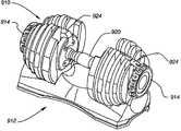
- FIG. 1is an isometric view of an adjustable dumbbell, in accordance with one embodiment of the present invention.
- FIG. 2is an isometric view of a support base, in accordance with one embodiment of the present invention.
- FIG. 3is an isometric view of an inner support, in accordance with one embodiment of the present invention.
- FIG. 4is a section view of the inner support of FIG. 3 taken along line 4 - 4 ;
- FIG. 5is an isometric view an inner disc, in accordance with one embodiment of the present invention.
- FIG. 6is a front view of a handle, in accordance with one embodiment of the present invention.
- FIG. 7is a front view of the adjustable dumbbell of FIG. 1 , with the weight plates removed;
- FIG. 8is an isometric view of a collar, in accordance with one embodiment of the present invention, the isometric view illustrating the outer face of the collar;
- FIG. 9is an isometric view of the collar of FIG. 8 , the isometric view illustrating the inner face of the collar;
- FIG. 10is a front view of a weight, in accordance with one embodiment of the present invention.
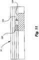
- FIG. 11is a section view of the weight plate of FIG. 10 taken along line 11 - 11 ;
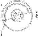
- FIG. 12is a front view of one implementation of a collar, in accordance with one embodiment of the present invention.
- FIG. 13is a front view of a second implementation of a collar, in accordance with one embodiment of the present invention.
- FIG. 14is a front view of a third implementation of a collar, in accordance with one embodiment of the present invention.
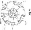
- FIG. 15is a front view of a fourth implementation of a collar, in accordance with one embodiment of the present invention.
- FIG. 16is a front view of one implementation of a selector knob, in accordance with one embodiment of the present invention.
- FIG. 17is a partial front section view of the handle, the inner support and the inner disc with the locking mechanism in the engaged position;
- FIG. 18is a partial front section view illustrating the locking mechanism in the unengaged position
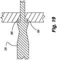
- FIG. 19is a representative front section view of a portion of the handle and the inner support
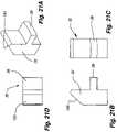
- FIG. 20 ais an isometric view of a locking pin, in accordance with one embodiment of the present invention.
- FIG. 20 bis a front view of the locking pin of FIG. 20 a;
- FIG. 20 cis a side view of the locking pin of FIG. 20 a;
- FIG. 20 dis a rear view of the locking pin of FIG. 20 a;
- FIG. 20 eis a top view of the locking pin of FIG. 20 a;
- FIG. 21 ais an isometric view of a plunger, in accordance with one embodiment of the present invention.
- FIG. 21 bis a side view of the plunger of FIG. 21 a;
- FIG. 21 cis a front view of the plunger of FIG. 21 a;
- FIG. 21 dis a top view of the plunger of FIG. 21 a;
- FIG. 22is an isometric view of one implementation of an adjustable dumbbell in engagement with one implementation of a support base
- FIG. 23is a partial isometric view of one implementation of an adjustable dumbbell, in accordance with one embodiment of the present invention.
- FIG. 24is a section view of one implementation of an adjustable dumbbell in engagement with one implementation of a support base
- FIG. 25is an isometric view of one implementation of a support base
- FIG. 26is a section view of one implementation of an adjustable dumbbell in engagement with one implementation of a support base
- FIG. 27is a partial section view primarily showing one implementation of an inner support and an inner disc, with the locking pin not engaged with the inner disc;
- FIG. 28is a section view of one implementation of an adjustable dumbbell removed from one implementation of a support base
- FIG. 29is a partial section view primarily showing one implementation of the inner support and the inner disc with the locking pin in partial engagement with the inner disc;
- FIG. 30is an isometric view of a locking pin, in accordance with one embodiment of the present invention.
- FIG. 31 ais a second isometric view of the locking pin of FIG. 30 ;
- FIG. 31 bis a front view of the locking pin of FIG. 31 a;
- FIG. 31 cis a side view of the locking pin of FIG. 31 a;
- FIG. 31 dis a rear view of the locking pin of FIG. 31 a;
- FIG. 31 eis a top view of the locking pin of FIG. 31 a;
- FIG. 32is an isometric view of a plunger, in accordance with one embodiment of the present invention.
- FIG. 33 ais a second isometric view of the plunger illustrated in FIG. 32 ;
- FIG. 33 bis a front view of the plunger of FIG. 33 a;
- FIG. 33 cis a side view of the plunger of FIG. 33 a;
- FIG. 33 dis a top view of the plunger of FIG. 33 a;
- FIG. 34is a section view of an alternative implementation of a base support, in accordance with one embodiment of the present invention.
- FIG. 35is an exploded isometric view of the base support structure shown in FIG. 34 ;
- FIG. 36is a section view of an alternative implementation of a base support, in accordance with one embodiment of the present invention.
- FIG. 37is an exploded isometric view of the base support structure shown in FIG. 36 ;
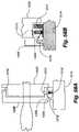
- FIG. 38is an isometric view of a base support structure of FIG. 36 ;
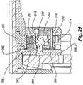
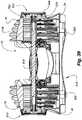
- FIG. 39is a section view of a base structure of and an adjustable dumbbell engaged therewith, in accordance with one embodiment of the present invention.
- FIG. 40is an exploded isometric view of a selector knob, in accordance with one embodiment of the present invention.
- FIG. 41is an isometric view of the assembled selector knob of FIG. 40 , showing the outer face of the selector knob;
- FIG. 42is an isometric view of an assembled selector knob of FIG. 40 , illustrating the inner face of the selector knob;
- FIG. 43is an isometric view of a number strip, in accordance with one embodiment of the present invention.
- FIG. 44is an isometric view of the number strip of FIG. 43 , the selector strip being formed into a generally circular structure;
- FIG. 45is an isometric view of one implementation of a handle, in accordance with one embodiment of the present invention.
- FIG. 46is a front section view of the handle of FIG. 45 ;
- FIG. 47is an isometric view of an inner support, in accordance with one embodiment of the present invention, the view illustrating the inner surface of the inner support;
- FIG. 48is an isometric view of the inner support of FIG. 47 , the view illustrating the outer surface of the inner support;
- FIG. 49is an isometric view of a weight plate, in accordance with one embodiment of the present invention.
- FIG. 50is an exploded isometric view of the weight plate of FIG. 49 ;
- FIG. 51is an isometric view of a weight plate with an over molded coating thereon, in accordance with one embodiment of the present invention.
- FIG. 52is an isometric section view of one implementation of a weight plate, in accordance with one embodiment of the present invention.
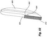
- FIG. 53is an isometric section view of an alternative weight plate, in accordance with one embodiment of the present invention.
- FIG. 54is an isometric section view of an alternative embodiment of a weight plate, in accordance with one embodiment of the present invention.
- FIG. 55is an isometric view of one implementation of an adjustable dumbbell in engagement with one implementation of a support base, in accordance with one embodiment of the present invention.
- FIG. 56is an isometric view of the adjustable dumbbell and support base of FIG. 55 , with the dumbbell in engagement with all of the weight plates;
- FIG. 57is an isometric view of the dumbbell and support base of FIG. 55 , with the dumbbell removed from the support base and in engagement with less than all of the weight plates.
- FIGS. 58 a and 58 bshow an alternative embodiment of the rotational control structure between the support disc and the inner disc, to keep the inner disc from rotating with respect to the handle when the dumbbell is in use.
- An adjustable dumbbell system of the present inventionprovides an adjustable dumbbell 10 that allows a user to easily select the weight of the dumbbell.
- the adjustable dumbbell system of the present inventionallows the user to place the adjustable dumbbell in a support base 12 , turn a selector knob 14 or knobs to engage a desired combination of weights 16 , and lift the adjustable dumbbell out of the base support to perform a desired exercise.
- the adjustable dumbbellwill have the desired combination of weights, and the unnecessary weights are left in the base support. Should the user desire a different dumbbell weight, the user places the adjustable dumbbell back in the support base, turns the selector knob to engage the desired weight, and lifts the adjustable dumbbell off of the support base with the desired weight.
- the adjustable dumbbellis configured such that it is difficult or impossible to turn the selector knob to add or remove weights.
- the adjustable dumbbell systemincludes an adjustable dumbbell 10 , such as shown in FIG. 1 , and a support base 12 , such as shown in FIG. 2 .
- the adjustable dumbbell 10includes a handle 18 , a pair of inner supports 20 , a pair of inner discs 22 , a plurality of weights 16 separated by a plurality of collars 24 , and a pair of outer selector knobs 14 .
- the adjustable dumbbell 10includes two end regions that, except as where otherwise described, are generally identical. Thus, when reference is made to one or more parts on one side of the adjustable dumbbell or base, it is to be understood that corresponding or similar part(s) are disposed on the other side or end region of the adjustable dumbbell or base.
- the inner supportis mounted on the handle adjacent to a central grip portion 26 of the handle. As described in more detail below, the inner support does not rotate with respect to the handle.
- the inner discis mounted on the handle immediately distal, or outside, of the inner support 20 .
- the plurality of collarsare positioned on the handle and extend distally along the handle 18 from the inner disc. The collars are interlocked together (i.e., with the adjacent collars), and with the inner disc 22 , such that the collars and the inner disc rotate together about the handle.
- the outer selector knob 14is positioned on the handle at the outer end of the outermost of the adjacent collars 24 .
- the outer selector knobis also interlocked with the adjacent collar so that as the outer selector knob is rotated, the outer selector knob also rotates the collars and the inner disc around the handle.
- the plurality of weights 16are spaced between adjacent collars and are selectively engaged by the collars depending upon the orientation of the outer selector knob 14 , as is described in more detail below.
- the support base 12receives the dumbbell 10 , when not in use, and allows a user to adjust the weight of the dumbbell, as well as to hold the weights that are not attached to the dumbbell.
- the userBefore using the dumbbell 10 , the user first determines the weight to be lifted and sets the respective selector knob 14 at each end of the dumbbell 10 while the dumbbell is in the support base 12 .
- the selector knobscause a pair or combination of pairs of weight plates 16 to be retained on the handle 18 .
- the userthen lifts the dumbbell out of the base. Any weight not retained with the adjustable dumbbell is left in the base. As shown in FIGS.
- the support baseincludes a bottom wall 28 , a plurality of positioning walls 30 , and a pair of plungers 32 .
- the bottom wallsupports the adjustable dumbbell and the weights.
- the positioning walls 30ensure that the adjustable dumbbell is properly aligned when it is inserted into the support base. Further, the positioning walls hold the weights upright and in the proper location relative to the adjustable dumbbell so that the adjustable dumbbell may be easily inserted into and removed from the support base.
- the positioning walls 30are spaced so as to fit between adjacent weights 16 when the dumbbell 10 rests in the support base 12 , and to keep any weight not attached to the dumbbell upright when the dumbbell is removed from the support base.
- the plungersextend upwardly from the support base.
- Each plungeris positioned to extend into a cavity formed in the inner support 20 of the adjustable dumbbell when the dumbbell is placed in the support base.
- the plungers 32deactivate a locking device, as described further below, to allow selection of different weights when the adjustable dumbbell is in the support base.
- the dumbbell inner support 20includes a spring-loaded pin 34 locking mechanism that prevents the inner disc 22 , the collars 24 , and the outer selector knobs 14 from rotating with respect to the handle.
- the plunger 32retracts the spring-loaded pin locking mechanism so that the outer selector knob can be turned, which in turn rotates the collars and the inner disc, to adjust the weight of the adjustable dumbbell.
- the weight of the adjustable dumbbellcan be adjusted by turning the pair of outer selector knobs 14 to selectively engage or disengage the plurality of weights 16 (on the same respective end of the handle as the knob) with the plurality of collars 24 when the dumbbell 10 is seated in the support base 12 .
- the dumbbellcannot, in most instances, be removed from the support base unless the weights 16 are fully engaged or disengaged by the collars.
- the dumbbellincludes a plurality of teeth 36 on the inner surface of inner disc 22 that can engage a protrusion 38 of the plunger 32 when the weights are not fully engaged or disengaged by the collars.
- the teethextend generally parallel to the axis of rotation of the disc, from the outer rim thereof. The teeth are spaced apart sufficiently to allow the protrusion to pass through when the collars are fully engaged, and to interfere with the movement of the protrusion when the collars are not fully engaged.
- the holes 40 , 42 for receiving the spring-loaded pin 34 and a ball detent 44are positioned in line with the space between adjacent teeth.
- the holes 40 , 42could be anywhere on the disc 22 as long as they cooperate with the spring-loaded pin as described.
- the dumbbellWhen the collars, inner disc and knob are properly aligned in rotation on the dumbbell, the dumbbell can be removed from the support base, and the spring-loaded pin locking mechanism re-engages the inner disc and prevents the inner disc, the collars 24 , and the outer selector knob 14 from rotating with respect to the handle 18 and the inner support.
- the weights 16when out of the base, the weights 16 are locked into place and the outer selector knob cannot be turned to select a different combination of weights.
- the plunger 32engages the spring-loaded pin 34 to disengage it from the inner disc 22 .
- the selector knob 14can then be rotated to rotate the collars 24 to select the desired weight.
- the ball detents 44help the user tell when he or she is at a secure rotation location and not between locations for selecting weight plates 16 .
- the knobalso has markers to indicate that the desired weight has been selected. This is described in greater detail below.
- the teeth 36 on the inner disc 22are engaged with the protrusion 38 of the plunger, thus keeping the inner disc, and the dumbbell, in the base.
- the protrusionpasses between the teeth and allows the dumbbell to be removed from the base.
- the plungerdisengages the spring-loaded pin 34 and allows the pin to be biased into the matching hole on the inner disc 22 to keep the inner disc from rotating relative to the support plate 20 and the dumbbell 10 .
- Thisalso keeps the collars 24 and selector knob 14 from turning since they are both keyed to the rotation of the inner disc 22 .
- the selector knobcannot be rotated to change the weight selection and cause the weight plates 16 on the dumbbell to become dislodged.
- the handle 18 of adjustable dumbbell 10includes a central grip portion 26 and a pair of end portions 46 , one on either end of the grip portion.
- the grip portion of the handleis preferably machined and provides a comfortable, ergonomic, and non-slip surface allowing a user to securely grip the adjustable dumbbell.
- the grip portionfurther includes a pair of flanges 48 adjacent to the end portions. The flanges extend beyond the outer periphery 50 of the end portions and provide a support surface 52 for the inner support 20 .
- the end portions 46also include keys 54 that extend beyond the outer periphery of the end portions.
- the keysextend radially from the handle's longitudinal center line, and extend a ways along the length to fit into a key way in the support plate 20 in order to keep the support plate from rotating on the handle 18 .
- inner and proximalrefer to a direction toward the central grip portion 26 of the handle
- outer and distalrefer to a direction toward the terminal ends 56 of the end portions 46 of the handle.
- the handleis generally symmetrical about the midpoint of the central grip portion.
- the central grip portionis slightly bulged to provide a comfortable and ergonomic surface to grasp.
- the handle 18has a generally decreasing radius.
- the radius of the handlebegins increasing at the flange 48 until the support surface 52 where the handle has a step decrease in the radius. This step decrease in radius extends around the handle except for one section, which forms the key 54 .
- the handleDistal of the key, the handle has a generally constant radius until the terminal end 56 of the handle.
- the area distal the keyis adapted to engage cooperating apertures in the inner disc 22 the collars 24 , and the outer selector knob 14 allowing those elements to slide onto the end portions.
- the inner support 20defines a generally centrally-formed aperture, such as an inner opening 58 , for receiving an end portion of the handle 18 .
- Each support plateis seated on one end portion 46 of the handle adjacent to the flange 48 of the central grip portion 26 .
- the aperture of the inner supportfurther includes a keyway 60 that receives the key 54 from the end portion of the handle and prevents the inner support from rotating with respect to the handle.
- the handlemay include a keyway for receiving a key mounted on the inner support place.
- the inner support 20also includes a peripheral channel 62 in the outer surface 64 of the inner support. Any other means of anchoring the inner support to the handle known in the art may be used.
- the inner supportfor example, may be anchored to the handle through the use of pins 66 as shown in FIG. 19 .
- the housing of the inner support plate 20is preferably constructed of a nylon-glass reinforced material, although it may be constructed of any other suitable material, such as metal or the like.
- the inner supportincludes the spring-loaded ball or ball detent 44 and the spring-loaded pin 34 that are biased to extend from within the inner support beyond the outer surface 64 of the inner support.
- FIG. 4shows a cross-sectional view of the inner support 20 showing the spring-loaded ball 44 and the spring-loaded pin 34 generally biased to an outer position and extending partially through holes 68 and 70 , respectively, in the outer surface 64 of the inner support.
- the inner supportfurther includes a cavity 72 and a cover plate 74 .
- the spring-loaded pinis housed within the cavity of the inner support and is generally biased to extend from the cavity through the hole 70 .
- the cover plateis removably attached with the inner surface 78 of the inner support, and provides access to the spring-loaded pin 34 in the cavity, and further provides a surface for the spring to engage and bias the spring-loaded pin outwardly from the outer surface.
- the spring-loaded pin 34is housed within the cavity 72 between the cover plate 74 and the outer surface 64 of the inner support 20 .
- the spring of the spring-loaded pinis seated against the cover plate.
- the pin 80(shown separately in FIGS. 20A-20E ) includes knob 82 that extends into the spring coil 84 .
- the springgenerally biases the pin 80 toward the hole 70 in the outer surface such that, absent any counteracting forces, the pin extends through the hole 70 for engagement of one of the apertures 40 of the inner disc 22 .
- the spring-loaded ball 44is housed within a separate cavity 86 of the inner support 20 directly above the cavity 72 .
- the spring 88 of the spring-loaded ballis seated against the inner surface of the cavity 86 .
- the ball 89is in engagement with the other end of the spring and is thus generally biased toward the hole.
- the ball 44is adapted to engage one of the detent recesses 42 of the inner disc 22 .
- the ballis retained by the inner disc.
- the ballis held by grease used to lubricate the ball detent.
- FIG. 5shows a isometric view of the inner surface 90 of the inner disc 22 .
- the inner discincludes teeth 36 , apertures 40 , detent recesses 42 , and a generally centrally located inner opening 92 for receiving the handle 18 .
- the teeth, apertures, and detent recessesare arranged concentrically on the inner disc.
- the teethare arranged around the perimeter 94 of the inner disc 30 and extend generally 90 degrees inwardly from the perimeter edge of the inner disc.
- the detent recessesare spaced radially inwardly from the apertures.
- the apertures and the detent recessesare angularly aligned with each other and are angularly offset from the teeth when the selector knob 14 is properly oriented to select the desired weight.
- the teeth of the inner disc 22extend into the peripheral channel 62 of the inner support 20 (see FIG. 23 ).
- the inner discis interlocked to the collars 24 and the outer selector knob 14 .
- the inner discis rotated about the handle 18 with respect to the inner support 20 , which is fixed with respect to the handle.
- the spring-loaded ball 44engages the detent recesses 42 to indicate the rotational position of the inner disc 22 to allow the user to clearly identify when the outer selector knob has been turned one full setting as described in more detail below.
- the spring-loaded pin 34 of the inner supportengages the corresponding aperture 40 to lock the inner support 20 to the inner disc 22 so that the outer selector knob 14 , the collars 24 , and the inner disc cannot rotate with respect to the inner support and the handle 18 .
- FIG. 7shows a cross-sectional view of the adjustable dumbbell 10 taken along the longitudinal centerline of the handle 18 without any weights 16 attached to the handle.
- the plurality of collars 24 and the outer selector knob 14are mounted on both of the end portions 46 of the handle and are arranged distally from the inner support 20 and the inner disc 22 .
- the inner disc, each of the collars, and the outer selector knobare interlocked and rotatably mounted on the end portion of the handle.
- the outer selector knob 14each of the collars 24 and the inner disc 22 are rotated together around the end portion 46 of the handle 18 .
- the inner supportremains stationary with respect to the handle, and the teeth 36 of the inner disc rotate within the peripheral channel 62 of the inner support.
- FIG. 8shows an isometric view of the inner surface of one of the collars 24 .
- the collarincludes one or more peripheral flanges 96 , inner opening 98 , extension sleeve 100 , and a plurality of insert tabs 102 .
- the one or more peripheral flangeseither engage and lift a weight 16 from the support base 12 , or do not engage a weight plate and allow it to remain in the support base depending upon the orientation of the collar.
- the inner opening and extension sleevereceive the end portion 46 of the handle 18 and allow for the collar 24 to rotate with respect to the handle.
- the extension sleeveextends from the inner surface 104 of the collar and allows for separation between the individual collars to form a space between adjacent collars to receive the weights 16 .
- the extension sleeve 100defines a terminal face 106 .
- the insert tabs 102extend axially inward from the terminal face of the extension sleeve, preferably from the outer periphery of the terminal face, for engagement with the outer surface of an adjacent collar or the inner disc 22 as described in more detail below.
- FIG. 9shows a isometric view of the outer surface of one collars 24 .
- the outer surface 108 of the collarincludes a plurality of indentations to receive the inserts 102 of an adjacent collar.
- the inserts and the indentations 110are keyed so that the collars can only be interconnected in one orientation.
- the insert 102 a and corresponding indentation 110 aare wider than the inserts 102 b and 102 c and indentations 110 b and 110 c so that the collars can only be connected in a particular orientation.
- the individual collarsmay be keyed such that the collars may only be assembled in one particular order along the dumbbell handle 18 in addition to being assembled in only one particular orientation with respect to one another.
- FIG. 10shows a front view of a weight 16 for the adjustable dumbbell 10 .
- the weighthas a generally round shape.
- the weightfurther forms a channel 112 for receiving the extension sleeve 100 of the collars 24 .
- the channelterminates at its inner end at semi-circular arc 114 having a constant radius R.
- the channelalso has a constant width W equal to the diameter D of the semi-circular arc.
- the channelallows the extension sleeve of the collar to turn within the channel and to only move the weight incidentally through friction.
- the channel 112necks out towards the periphery 116 of the weight 16 for receiving a stabilizing bar 118 (also referred to as bridge) (shown in FIGS. 7 and 22 ).
- a stabilizing bar 118also referred to as bridge
- the stabilizing barextends across the upper portion of the channels of the weights to secure the weights and prevent the weights from rotating with the collars 24 during weight selection.
- the weights 16extend above the height of the collars so that the bar does not interfere with the rotation of the collars.
- the barcan be attached at one end to the inner support 20 and/or to the handle 18 so that the bar does not rotate with the inner disc 22 or the collars.
- the bar 118extends into a peripheral groove 120 of the outer selector knob 14 (shown in FIG. 7 ). As the outer selector knob 14 rotates, the bar 118 is positioned within the peripheral groove 120 without rotating.
- an engagement tab 122extends from the outer surface of the weight 16 to engage a particular peripheral flange 96 of one of the collars 24 .
- the particular peripheral flangeis determined by the desired weight to be lifted by the dumbbell 10 .
- FIG. 11further shows a cross-sectional view of the weight shown in FIG. 10 taken along section line A-A. As shown in FIG. 11 , the tab extends from the front surface 124 of the weight for engagement with the peripheral flanges of the collars.
- peripheral flanges 96 of the collars 24are clocked to the tabs 122 of the weights 16 , i.e., there is a known defined rotational relationship between the peripheral flanges and tabs. A certain orientation of the outer selector knob 14 will engage none, one, or more particular peripheral flanges to the tabs of the weights to allow the user to select a predefined amount of weight.
- the number of incremental weight selections available on the dumbbell 10can be varied by varying the minimum width of the peripheral flanges 96 or by varying the circumference available for the peripheral flanges. For example, if the minimum width of the peripheral flanges is decreased, the number of peripheral flanges that may be placed around a constant circumference may be increased, thus increasing the number of incremental weight selections that may be made. Alternatively, by increasing the radius of the peripheral flange 96 from the center of the collar 24 , the circumference available for positioning flanges is increased and the number of constant width peripheral flanges that may be placed around the circumference of the collar is increased, thus increasing the potential number of incremental weight selections that may be made.
- the peripheral flangesare preferably located along the periphery of the collar 24 so that the circumference available to position the peripheral flanges 96 is maximized
- the flangesmay be located either at the periphery of the collar or may be located any distance away from the periphery of the collar towards the center of the collar.
- the collarcan have an outer diameter of 84 mm and a radius from the center of the collar to the peripheral flange of 32.5 mm.
- the tab 122has a width 125 of about 13 mm and height 126 of about 9.5 mm.
- the minimum spacing between the peripheral flanges 96 of the collars 24is at least 14 mm to allow the tab 38 to slide through the spacing when the weight is not selected.
- FIG. 12shows a front view of a first selection collar 24 a located adjacent the inner disc 22 on the end portion 46 of the handle 18 .
- the first selection collarincludes one flange 96 a extending around a portion of the periphery of the first selection collar.
- the peripheral flangemay extend around the periphery of the first selection collar 24 a for an angle ⁇ of approximately 192 degrees.
- the extension sleeve 100 of the first selection collaris seated within the channel 112 of the first weight 16 a of the adjustable dumbbell 10 (see FIG. 1 ).
- the peripheral flange 96 arotates around the end portion 46 of the handle 18 . If the first weight 16 a is selected by the user, the peripheral flange is positioned under the tab 122 of the first weight. Thus, when the adjustable dumbbell is lifted out of the support base 12 , the peripheral flange 96 a of the first selection collar 24 a engages the tab 122 of the first weight 16 a and lifts the first weight out of the support base. If the first weight 16 a is not selected, however, the peripheral flange 96 a of the first selection collar 24 a is not under the tab 122 of the first weight. As the adjustable dumbbell 10 is lifted out of the support base 12 , the first weight remains in the support base, supported by the positioning walls 30 of the support base.
- FIG. 13shows a front view of a second selection collar 24 b located on the end portion 46 of the handle 18 immediately distal of the first selection collar 24 a .
- the second selection collarincludes one flange 96 b extending around a portion of the periphery of the second selection collar.
- the flangemay extend around a periphery of the second selection collar 24 b for an angle ⁇ of approximately 96 degrees.
- the extension sleeve 100 of the second selection collaris seated within the channel 112 of the second weight 16 b and is interlocked with the first selection collar 24 a so that the collars turn together.
- the peripheral flange 96 brotates around the end portion 46 of the handle 18 . If the second weight 16 b is selected by the user, the peripheral flange 96 b is positioned under the tab 122 of the second weight 16 b .
- the peripheral flange 96 b of the second selection collar 24 bengages the tab 122 of the second weight 16 b and lifts the second weight out of the support base.
- the peripheral flange of the second selection collaris not under the tab of the second weight and the outer end portion of the handle passes out of the channel 112 without lifting the second weight out of the support base.
- the adjustable dumbbellis lifted out of the support base 12 , the second weight 16 b remains in the support base, supported by the positioning walls 30 of the support base.
- FIG. 14shows a front view of a third selection collar 24 c located on the end portion 46 of the handle 18 immediately distal of the second selection collar 24 b.
- the third selection collarincludes three flanges 96 c, 96 d, and 96 e extending around a portion of the periphery of the third selection collar 24 c.
- the flanges 96 c, 96 d, and 96 emay extend around a periphery of the third selection collar 24 c for angles ⁇ , ⁇ , and ⁇ of approximately 72, 48, and 72 degrees, respectively.
- the extension sleeve 100 of the third selection collar 24 cis seated within the channel 112 of the third weight 16 c of the adjustable dumbbell 10 and is interlocked to the second selection collar 24 b .
- the three peripheral flanges 96 c, 96 d, and 96 erotate around the end portion of the handle. If the third weight 16 c is selected by the user, one of the peripheral flanges 96 c, 96 d, and 96 e is positioned under the tab 122 of the third weight 16 c. Thus, when the adjustable dumbbell is lifted out of the support base 12 , one of the peripheral flanges 96 c, 96 d, and 96 e of the third selection collar 24 c engages the tab 122 of the third weight 16 c and lifts the third weight out of the support base.
- the third weightis not selected, however, none of the peripheral flanges 96 c , 96 d , and 96 e of the third selection collar 24 c is under the tab 122 of the third weight 16 c and the outer end portion 46 of the handle 18 passes out of the channel 112 without lifting the third weight out of the support base 12 .
- the third weight 16 cremains in the support base, supported by the positioning walls 30 of the support base.
- FIG. 15shows a front view of a fourth selection collar 24 d located on the end portion 46 of the handle 18 immediately distal of the third selection collar 24 c.
- the fourth selection collarincludes five flanges 96 f , 96 g , 96 h , 96 i , and 96 j extending around a portion of the periphery of the fourth selection collar 24 d.
- the flanges 96 f , 96 g , 96 h , 96 i , and 96 jmay extend around a periphery of the fourth selection collar 24 d for angles ⁇ , ⁇ , ⁇ , ⁇ , and ⁇ of approximately 48, 24, 24, 48, and 48 degrees, respectively.
- the extension sleeve 100 of the fourth selection collar 24 dis seated within the channel 112 of the fourth weight 16 d of the adjustable dumbbell 10 and is interlocked with the third selection collar 24 c .
- the five peripheral flanges 96 f , 96 g , 96 h , 96 i , and 96 jrotate around the end portion 46 of the handle 18 If the fourth weight 16 d is selected by the user, one of the peripheral flanges 96 f , 96 g , 96 h , 96 i , and 96 j is positioned under the tab 122 of the fourth weight 16 d.
- the adjustable dumbbell 10when the adjustable dumbbell 10 is lifted out of the support base 12 , one of the peripheral flanges 96 f , 96 g , 96 h , 96 i , and 96 j of the fourth selection collar 24 d engages the tab 122 of the fourth weight 16 d and lifts the fourth weight out of the support base. If the fourth weight is not selected, however, none of the peripheral flanges 96 f , 96 g , 96 h , 96 i , and 96 j of the fourth selection collar is under the tab 122 of the fourth weight and the outer end portion 46 of the handle passes out of the channel 112 without lifting the fourth weight out of the support base 12 . As the adjustable dumbbell is lifted out of the support base, the fourth weight 16 d remains in the support base, supported by the positioning walls 30 of the support base.
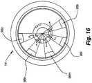
- FIG. 16shows a front view of the outer selector knob 14 located at the distal end of the end portion 46 of the handle 18 immediately distal of the fourth selection collar 24 d.
- the outer selector knobincludes five flanges 96 k , 96 l , 96 m , 96 n , and 96 o extending around a portion of the periphery of the outer selector knob.
- the collars 24have an outer diameter of 84 mm and a radius from the center to the peripheral flange 96 of 32.5 mm
- the flanges 96 k , 96 l , 96 m , 96 n , and 96 omay extend around a periphery of the outer selector knob 14 for angles ⁇ , ⁇ , o, ⁇ , and ⁇ of approximately 24, 24, 24, 24, and 24 degrees, respectively.
- the extension sleeve 100 of the outer selector knobis seated within the channel 112 of the fifth weight 16 e of the adjustable dumbbell 10 and is interlocked with the fourth selection collar 24 d .
- the five peripheral flanges 96 k , 96 l , 96 m , 96 n , and 96 orotate around the end portion 46 of the handle 18 . If the fifth weight 16 e is selected by the user, one of the peripheral flanges 96 k , 96 l , 96 m , 96 n , and 96 o is positioned under the tab 122 of the fifth weight.
- the adjustable dumbbellwhen the adjustable dumbbell is lifted out of the support base 12 , one of the peripheral flanges 96 k , 96 l , 96 m , 96 n , and 96 o of the outer selector knob engages the tab 122 of the fifth weight and lifts the fifth weight out of the support base. If the fifth weight 16 e is not selected, however, none of the peripheral flanges 96 k , 96 l , 96 m , 96 n , and 96 o of the outer selector knob is under the tab 122 of the fifth weight 16 e and the outer end portion 46 of the handle 18 passes out of the channel 112 without lifting the fifth weight out of the support base 12 . As the adjustable dumbbell 10 is lifted out of the support base, the fifth weight remains in the support base, supported by the positioning walls 30 of the support base.
- the outer selector knob 14has to be turned in the same direction, e.g., clockwise, to select the same weight setting on both sides. This requires turning one outer selector knob toward the user and the other outer selector knob away from the user. If desired, however, one skilled in the art would readily appreciate that mirror image collars could be used on opposite ends of the adjustable dumbbell so that the outer selector knobs are both turned toward the user or are both turned away from the user in order to select the same weight setting on both ends.
- the adjustable dumbbell 10includes the spring-loaded pin 34 locking mechanism to secure the weights 16 in place when the pin is engaged with the inner disc 22 , and to allow the weight of the dumbbell to be adjusted when the pin is disengaged from the inner disc.
- FIG. 17shows a partial cross-section view of the adjustable dumbbell with the spring-loaded pin locking mechanism engaged in one of the apertures 40 of the inner disc and wherein the spring-loaded ball 44 is seated within one of the detent recesses 42 of the inner disc.
- the spring-loaded pinlocks the inner disc by engaging one of the plurality of apertures of the inner disc and prevents the inner disc from rotating.
- the spring-loaded pin 34secures each weight 16 by preventing the peripheral flanges 96 of the collars 24 from rotating with respect to the tabs 122 of the weights.
- the spring-loaded pin in combination with the stabilizing bar 118ensures that the weights are secured to the adjustable dumbbell 10 and stabilized during use and selection.
- the receiving hole 40is positioned on the inner disc 22 so that the pin is oriented with the particular hole only when the collars 24 are fully engaged with the desired weight plates 16 . The pin will only lock with the inner plate when the collars and weight plates are properly oriented.
- FIG. 18shows a cross-sectional view of the adjustable dumbbell 10 with the spring-loaded pin 34 locking mechanism disengaged from the inner disc 22 and wherein the outer selector knob 14 is between settings, i.e., the spring-loaded ball 44 is not seated in a detent recess 42 of the inner disc. Since the spring-loaded pin is disengaged from the inner disc, the inner disc is free to rotate with respect to the inner support 20 and, thus, the outer selector knob may be rotated to adjust the weight of the dumbbell. As shown in FIGS. 2 and 18 , the plunger 32 extends upwardly from the bottom wall to engage the bottom of the pin structure.
- the plungerincludes an upper sloped cam surface 130 and the protrusion 38 that extends from the plunger 32 outwardly towards the end of the support base 12 .
- the plungeris positioned on the support base such that the protrusion extends into the cavity 72 of the inner support 20 when the adjustable dumbbell 10 is placed onto the support base.
- the upper sloped cam surface of the plungercontacts the downwardly angled surface 132 of the spring-loaded pin 34 inside the cavity of the inner support.
- the upper sloped cam surface 130 of the plunger 32engages the downwardly angled surface of the spring-loaded pin and retracts the spring-loaded pin from its engaged position in an aperture 40 of the inner disc 22 and pulls the pin 80 out of the aperture of the inner disc.
- the spring-loaded pinis retracted from the aperture of the inner disc, the inner disc is unlocked and can rotate with respect to the inner support 20 , thus allowing the weight selection to be made.
- the plunger 32extends into the cavity 72 of the inner support 20 .
- the upper sloped cam surface 130 of the plungerengages the downwardly angled surface 132 of the spring-loaded pin 34 and retracts the spring-loaded pin from the aperture 40 of the inner disc 22 allowing the inner disc to rotate with respect to the inner support.
- the weight of the dumbbellcan be adjusted by rotating the outer selector knob 14 .
- the upper sloped cam surface of the plungeris disengaged from the downwardly angled surface of the spring-loaded pin of the inner support.
- the spring 84pushes the pin 80 outwardly to its extended, biased position where it engages one of the plurality of apertures of the inner disc preventing the inner disc from rotating with respect to the inner support 20 (assuming the hole 40 is properly aligned with the pin 34 ).
- the spring-loaded pinengages one of the apertures 40 of the inner disc 22 and prevents the inner disc, the collars 24 , and the outer selector knob 14 from rotating with respect to the inner support 20 and the handle 18 .
- the respective angles of the upper sloped cam surface 130 of the plunger 32 and the downwardly angled surface 132 of the spring-loaded pin 34determine how far the spring-loaded pin is retracted from its outward, biased position.
- the upper sloped cam surface of the plunger and the downwardly angled surface of the spring-loaded pinis sloped at an angle of about 40 degrees.
- the length of the protrusion 38 of the plungerextends from the body of the plunger is about 5 mm.
- the protrusionmay be slightly curved to match the curvature of the teeth 36 that extend from the perimeter of the inner disc 22 .
- FIGS. 20A-20Eshow one implementation of a pin of FIG. 18 .
- FIGS. 21A-21Eshow one implementation of a plunger.
- the spring-loaded ball 44engages a detent recess 42 to indicate when the inner disc 22 has been turned to a position such that one or more weights are fully engaged, i.e., one or more of the peripheral flanges 96 of the collars 24 are fully engaged with the tabs 122 of the weights 16 .
- the adjustable dumbbell 10may be arranged such that no weights are engaged.
- the spring-loaded ball and detent recessmake an audible and/or other sensory feedback to the user when the weights have been properly secured by the peripheral flanges of the collars. This feature may be helpful for a user to determine the proper position of the weight selector knob 14 .
- the detent recesses 42 of the inner disc 22are angularly offset from the teeth 36 of the inner disc.
- the spring-loaded ball 44is seated within one of the detent recesses as shown in FIG. 17 , none of the teeth of the inner disc extend into the cavity 72 of the inner support 20 .
- the plunger 32 of the support base 12is free to move into or out of the cavity 72 of the inner support 20 and thus the teeth 36 do not engage the protrusion 38 , which would keep the dumbbell 10 from disengaging from the base.
- the spring-loaded pin 34is also aligned to engage one of the apertures of the inner disc when the spring-loaded ball 44 is seated within one of the detent recesses.
- the spring-loaded pinis aligned with one of the apertures of the inner disc and the bias of the spring pushes the pin into the aperture of the inner disc.
- the spring-loaded ball 44is not seated within one of the detent recesses 42 , i.e., the collars 24 of the adjustable dumbbell are between settings and the peripheral flanges 96 of the collars are not fully engaged with the tabs 122 of the selected weights 16 , one of the offset teeth 36 of the inner disc 22 protrudes into the cavity 72 of the inner support 20 .
- the plunger 32cannot be removed from the cavity of the inner support, i.e., the dumbbell 10 cannot be removed from the support base 12 , because the tooth locks the protrusion 38 of the plunger within the cavity.
- the dumbbellcan only be removed from the support base if the spring-loaded ball detent 44 is seated within one of the detent recesses 42 and the flanges 96 of the collars 24 are fully engaged with the tabs 122 of the weights 16 .
- the full engagement of the flanges of the collars and the weight platescan be indicated in other ways than the spring detents, such as by a precise marking of the selection knob 14 orientation or other means. A position strip for use in indicating the selected orientation of the selector knob is described in greater detail below.
- the adjustable dumbbell 10allows for adjustments in weight from 5 pounds to 52.5 pounds.
- the combined weight of the adjustable dumbbell 10 without any weights 16 attachedis 5 pounds;
- the first weight 16 a positioned between the inner disc 22 and the second selection collar 24 a (first) or 24 b (second)is a 7.5 pound weight;
- the second weight 16 b positioned between the first and second selection collars 24 a and 24 b , respectively,is also 7.5 pounds;
- the third weight 16 c positioned between the second and third selection collars 24 b and 24 c , respectively,is 5 pounds;
- the fourth weight 16 d positioned between the third and fourth selection collars 24 c and 24 d , respectively,is 2.5 pounds; and
- the fifth and outer weight 16 e positioned between the fourth selection collar 24 d and the outer selector knob 14 , respectively,is 1.25 pounds.
- This arrangementallows for fifteen incremental weights of 5, 7.5, 10, 12.5, 15, 17.5, 20, 22.5, 25, 30, 35, 40, 45, 50, and 52.5 pounds that may be selected for the adjustable dumbbell 10 .
- the weights 16are preferably arranged such that the weights range from the heaviest weights closest to the central grip portion 26 of the handle 18 and the lightest weights furthest from the central grip portion of the handle.
- the weightscould also be arranged in any other order as desired, with the appropriate positioning of the collars 24 to provide for the proper weight selection.
- the dumbbell 210includes a spring-loaded pin 212 locking mechanism, a plunger 214 , and a retaining bar 216 .
- the support base 218includes an engagement surface 220 and a protrusion 222 .
- the shoulder engagement surfaceengages the plunger housed in the inner support 224 of the dumbbell to disengage the spring-loaded pin locking mechanism from the inner disc 226 when the dumbbell is located on the support base.
- the shoulder engagement surfacealso protects the protrusion from being inadvertently broken off or otherwise damaged.
- the protrusion 222extends into the peripheral channel 228 of the inner support for selective engagement with the teeth 230 of the inner disc 226 when the weights 16 are not fully engaged or disengaged by the collars 232 .
- the spring-loaded pin 212 locking mechanismprevents the inner disc 226 , the collars 232 , and the outer selector knob 234 from rotating with respect to the handle 236 .
- the engagement surface 220contacts the plunger 214 and retracts the spring-loaded pin locking mechanism so that the outer selector knob can be turned to adjust the weight of the adjustable dumbbell.
- the weight of the adjustable dumbbellcan be adjusted by turning the pair of outer selector knobs to selectively engage or disengage the plurality of weights 16 with the plurality of collars when the dumbbell is seated in the support base.
- FIGS. 28 and 29show cross-sectional views of the adjustable dumbbell 210 with the spring-loaded pin 212 locking mechanism engaged in one of the apertures 238 of the inner disc 226 and wherein the spring-loaded ball 240 is seated within one of the detent recesses 242 of the inner disc.
- the spring-loaded pinlocks the inner disc by engaging one of the plurality of apertures of the inner disc and prevents the inner disc from rotating. Since the inner disc 226 is interlocked with the collars 232 and the outer selector knob 234 , the spring-loaded pin secures each weight by preventing the peripheral flanges of the collars from rotating with respect to the tabs 122 of the weights 16 .
- the spring-loaded pin 212ensures that the weights are secured to the adjustable dumbbell until the dumbbell is replaced into the support base 218 .
- FIGS. 26 through 27show cross-sectional views of the adjustable dumbbell 210 with the spring-loaded pin 212 locking mechanism disengaged from the inner disc 226 . Since the spring-loaded pin 212 is disengaged from the inner disc 226 , the inner disc is free to rotate with respect to the inner support 224 and, thus, the outer selector knob 234 may be rotated to adjust the weight of the dumbbell 210 . As shown in FIGS. 25 and 27 the shoulder engagement surface 220 extends upwardly from the support base 218 . The engagement surface extends into the cavity 244 of the inner support to engage the plunger 214 of the inner support. The plunger (or slider) (see, e.g., FIG. 32 and FIGS.
- 33A-33Dincludes a lower engagement surface 246 , an upper sloped cam surface 248 , and a slot 250 .
- Retaining bar 216extends through the slot of the plunger and retains the plunger within the cavity of the inner support yet allows the plunger to slide along at least one axis, e.g., vertically, within the cavity of the inner support.
- the engagement surface 220 of the support basecontacts the lower engagement surface 246 of the plunger 214 and urges the plunger vertically along the path defined by the slot 250 of the plunger.
- the upper sloped cam surface 248 of the plungeris brought into contact with the downwardly angled surface 252 of the spring-loaded pin 212 .
- the upper sloped cam surface of the plungerengages the downwardly angled surface of the spring-loaded pin and retracts the spring-loaded pin from its engaged position in an aperture 238 of the inner disc 226 and pulls the pin 254 out of the aperture of the inner disc (see, e.g., FIG. 27 ).
- the spring-loaded pin 212is retracted from the aperture of the inner disc, the inner disc is unlocked and can rotate with respect to the inner support.
- the adjustable dumbbellmay also be configured such that the support base is not required to release the weight plates.
- the plungermay be arranged to extend beyond the bottom plane of the adjustable dumbbell so that the plunger will engage a surface, such as a floor or table, if the adjustable dumbbell is set thereon. Upon engagement with the floor or other surface, the plunger is moved into engagement with the locking device to disengage the support plate from the inner disc and thus allow the selector knob and collars to turn freely.
- the engagement surface 220 of the support basecontacts the lower engagement surface 246 of the plunger 214 and urges the plunger further within the cavity 244 of the inner support 224 .
- the spring-loaded pinretracts from the aperture 238 of the inner disc 226 allowing the inner disc to rotate with respect to the inner support 224 . In this position, the weight of the dumbbell 210 can be adjusted by rotating the outer selector knob 234 .
- the bias imparted by the spring 256 of the spring-loaded pin 212urges the spring-loaded pin outwardly towards the inner disc 226 .
- the downwardly angled surface 252 of the spring-loaded pinengages the upper sloped cam surface 248 of the plunger 214 and urges the plunger away from the spring-loaded pin and the upper sloped cam surface of the plunger is disengaged from the downwardly angled surface of the spring-loaded pin. Gravity can also assist in moving the plunger downwardly.
- the spring 256pushes the pin 254 outwardly to its extended, biased position where it engages one of the plurality of apertures 238 of the inner disc 226 and prevents the inner disc from rotating with respect to the inner support 224 .
- the spring-loaded pin 212engages one of the apertures of the inner disc and prevents the inner disc, the collars 232 , and the outer selector knob 234 from rotating with respect to the inner support and the handle 236 .
- the respective angles of the upper sloped cam surface 248 of the plunger 214 and the downwardly angled surface 252 of the spring-loaded pin 212determine how far the spring-loaded pin is retracted from its outward, biased position.
- the upper sloped cam surface of the plunger and the downwardly angled surface of the spring-loaded pinare sloped at an angle of about 40 degrees from vertical.
- the protrusion 222may also be slightly curved to match the curvature of the teeth 230 that extend from the perimeter of the inner disc 226 as described above.
- the adjustable dumbbell 210cannot be removed from the support base 218 unless the weights 16 are fully engaged or disengaged by the collars 232 .
- the inner support 224 of the dumbbellincludes a plurality of teeth 230 that engage the protrusion 222 when the weights are not fully engaged or disengaged by the collars. When the weights are not fully engaged by the collars, the teeth engage the protrusion and prevent the protrusion from exiting the cavity 244 of the inner support, thus preventing the dumbbell from being removed from the support base.
- the spring-loaded pin 212 locking mechanismre-engages the inner disc 226 and prevents the inner disc, the collars 232 , and the outer selector knob 234 from rotating with respect to the handle 236 and the inner support 224 .
- the weights 16are locked into place and the outer selector knob cannot be turned to select a different combination of weights.
- the outer selector knobincludes circular-shaped indentations around its perimeter to allow a user to securely grip and turn the outer selector knob while adjusting the weight of the dumbbell.
- the outer selector knobmay include other shaped indentations or protrusions to provide a secure gripping surface for the user.
- the outer selector knobmay include V-shaped indentations to provide the gripping surface.
- the central grip portion of the handleincludes an overlay to allow a user to more securely grip the dumbbell during use.
- the overlaymay include a soft, compliant rubber or rubber-like non-slip material.
- the overlaymay include a textured grip surface to allow a user to securely grip the dumbbell.
- the grip overlaymay include elongated oval shaped protrusions that extend beyond the outer surface of the overlay to aid a user in gripping the dumbbell.
- the overlaymay include depressions or holes that provide a gripping surface.
- the base 310is made of a moldable plastic material sufficiently strong to support the dumbbell 10 when positioned therein. Since the dumbbell is handled while in the base, for instance to change the weight selection, it is helpful for the base to be stable on the support surface on which it sits. In addition, as the dumbbell is being removed from the base, or set back into the base, it is helpful for the base to not move easily during these steps. Since the dumbbell is set into the base with the weight plates 16 being received in their own respective sections, if the base moves easily on the support surface, the removal and return of the dumbbell from and to the base is more difficult.
- FIG. 34is a section view of one example of the base 310 without the dumbbell 10 .
- FIG. 35shows an exploded view of the base top portion 312 , plate 314 with weight bars 316 , and base bottom portion 318 .
- Other types, amounts, or positions of weightscould be used to anchor the base.
- the basehas a top portion and a bottom portion, and a plate held between the two portions.
- Fasteners 320extend though the non-skid feet 322 , the bottom portion, the plate, and into the top portion to hold the assembly together.
- the three steel weight bars 316having a total weight of approximately 5 pounds are attached to and supported by the plate 314 to provide significant weight to the base 310 and keep it from moving around easily on the support surface.
- Non-skid feet 322are positioned on the bottom portion to help keep the base stable on the support surface.
- the bottom portion 318 of the basehas an arcuate curve 324 upward between the ends of the base, which provides some spacing between the base and the support surface. Since the plate supporting the weight bars is rigid and supports the weight blocks itself, the bottom portion of the base does not have to support the weight blocks.
- FIGS. 34 and 35also show the shoulder engagement 326 for actuating the release mechanism in the dumbbell 10 , as well as the protrusion 328 for locking the inner plate into the base when the weight selector is not in fully-selected position.
- FIGS. 36 through 38show an alternative embodiment of the base 410 for the dumbbell 10 with a different weight structure for anchoring the base on the support surface.
- FIG. 36shows an upper base housing 412 , a lower base housing 414 , and a weight pack 416 positioned and held between the upper and lower base housings. Fasteners 418 extend though the non-skid feet 420 , the bottom portion, the weight pack, and into the top portion to hold the assembly together.
- the weight packis a blow-molded plastic container structure that contains steel sand and concrete (or any other weight substance, including liquid, ball bearings, sand, or the like). While the blow-molded container is structural, it could be flexible, such as a plastic bag-like container, as long as it sufficiently contains the weight material inside.
- FIG. 37shows an exploded view of the alternative embodiment of the base, with the upper housing 412 , weight pack 416 , lower portion 414 of the housing, and non-skid feet 420 .
- handles recesses 422are molded into the ends 424 of the bases to make transporting the dumbbell base, or the combination of the dumbbell and base more convenient. See FIGS. 34-38 .
- handle protrusionscould also be formed on the base.
- the selector knob 510 for selecting the weight load on the dumbbell 10is shown in several figures, including FIGS. 39 through 43 .
- the selector knobis generally circular, and made of an outer piece 512 , an inner piece 514 and a weight selector indicator 516 .
- the outer and inner piecescan be made of glass filled nylon.
- Most of the knobis covered with an over molded material, such as a polymer or similar material like Kraton® or Santoprene®, preferably having a shore hardness of 60 or so.
- a selector knobis positioned over each end of the handle bar 518 , and secured with a screw fastener 520 or the like, and can be either permanently mounted or removable.
- Each knob 510can be rotated with respect to the handle bar.
- the inner piece 514 of the knobhas a collar 522 formed around a central aperture 524 and extending inwardly (towards the middle of the handle) from the inner side for engaging the outer surface of the adjacent collar.
- the knob collarhas keyed protrusions to insert into the corresponding recesses in the adjacent collar to rotationally engage the knob collar with the adjacent collar, as described in more detail herein. See FIGS. 39 and 42 .
- the inner surface of the inner piece 514also has tabs 526 for engaging the adjacent weight plate 16 as determined by the selection of the load on the dumbbell 10 . See FIG. 42 .
- the selector knob 510has indicator markings formed thereon.
- the weight selector indicator 516 portion of the knobis a strap 528 formed by molding a material, such as Nylon 6 or the like, into a long piece having several sections 530 connected by a living hinge 532 .
- a raised number 534is formed on the outer surface 536 of each section.
- a positioning tab 538is formed on the inner surface 540 of a few of the sections 530 . The positioning tabs are formed such that when the strap 528 is formed into a circle (see FIG. 44 ) for positioning on the knob 510 , the tabs insert into corresponding slots in the knob to insure the proper orientation of the various raised numbers.
- the position of the strap on the knobis important because the various numbers are the indicators for the selected weight on the dumbbell 10 , so the strap should be keyed, or coordinated, with orientation of the knob, which is coordinated with the collar 522 positions, so that the weight selector numbers 534 are accurate.
- the edges of each of the sections 530 of the strap 528are beveled.
- the outer piecehas a beveled annular recess 544 for receiving the beveled edges of the sections of the strap, thus effectively clamping the strap onto the assembled knob. See FIGS. 39 , 41 , and 42 .
- the recessed annular rim 542 on the inner piece 514 of the knob 510can also have a beveled recess on its inner edge to receive the beveled edges of the sections annular and similarly clamp the strap onto the knob.
- the over mold materialis then applied to the outer surfaces of the knob. Some of the outer surfaces are not covered with the over mold material, such as the inner face of the inner piece 514 , which has to connect to the adjacent collar.
- the gripping surfaceis covered with the over molded material to enhance the gripping characteristics.
- the top surface of the numbers on the strap 528are not covered with the over mold material so that the weight indicator numbers 534 can be seen in a contrasting color with ease. This is accomplished by insuring that the mold used in applying the over molded material contacts the top surface of the numbers in order to keep the over mold material from covering up the number indicators. The top surface of the numbers are then flush with the top surface of the over molded material, yet can be seen clearly due to the contrast of colors with the over molded material.
- the arrows 546 shown in FIG. 41 associated with each number 534are formed on the inner piece 514 of the knob 510 .
- the over moldis designed to contact the top of the arrows along with the top of the numbers on the strap 528 during the molding process in order to allow the top surface of both the numbers and the arrows to be flush with and visible to the user.
- the numbers and arrowscould be slightly above flush with the material is compressed when contacted with the mold, so that when the mold is removed, the top surfaces of the numbers and arrows expand slightly above the top surface of the over molded material, for an additional tactile feel.
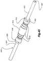
- FIGS. 45 and 46An alternative embodiment of the bar 610 is shown in FIGS. 45 and 46 .
- the baris shown as a cylindrical rod 612 (hollow or solid) extending through a separate grip portion 614 .
- the grip portionis contoured for comfortably handling a load, and can have a few regions of friction enhancing material 616 formed thereon.
- the grip portionis held to the bar with a pair of set screw fasteners or the like.
- the grip portion of the baris formed from steel; however, other suitable materials, such as aluminum, rubber, polymers, and the like may be employed.
- Two opposing slots 618are formed on both ends 620 of the grip portion.
- These slotsreceive tabs 720 formed on the inner support 710 , as described further below, to rotationally engage the inner support with the end of the grip portion of the handle. This keeps the inner disc from rotating independently of the grip portion and bar. Both ends of the rod have threaded holes 622 for receiving the fastener for attaching the end knob 510 to the bar.
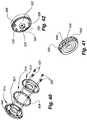
- FIGS. 47 and 48An alternative structure for the inner support 710 is shown in FIGS. 47 and 48 .
- the inner supportmounts on either end of the grip portion 614 of the bar 610 .
- the inner support shown in FIGS. 47 and 48includes an inner surface 712 (see FIG. 47 ) and an outer surface 714 (see FIG. 48 ).
- a central aperture 716is formed through the support, with an enlarged recess 718 formed around the central aperture on the inner surface.
- Two opposing tabs 720extend radially into the recess for engaging the corresponding slots 620 on the grip portion 614 of the handle 18 , as discussed with respect to the bar 610 structure herein.
- a cutout area 722 at the top of the supportreceives and anchors (i.e.
- a bottom edge 728 of the supportis flat for engaging the base, and a recess 730 is formed in the support at the flat edge for receiving the shoulder engagement 326 structure and the protrusion 328 , as described above.
- An opening 732 in the recessextends to the inner surface to allow access to the recess for positioning the spring-loaded pin 34 portion of the locking device into the support, as well as for positioning the ball-detent 44 structure in the support.
- a cutout 734is formed over the opening to the recess to receive a cover plate 74 .
- the aperture 736 at the bottom of the recessis for the pin 216 that slidably retains the slide engager/plunger 214 (See FIG. 32 ).
- FIG. 48shows the outer surface 714 of the inner support.
- the outer surfaceshows several bracing features 738 to provide sufficient structural strength to the support.
- a groove 740extends around the edge of the support for receiving the teeth on the inner disc, which alternately engage with and disengage from the protrusion 328 during the weight plate selection, as described elsewhere herein.
- the central aperture 716 for receiving the rod 612is shown, and a notch 742 is formed at the top of the support for receiving the bridge 118 .
- the recess 744 at the bottomextends into a housing 746 that has three apertures 748 formed therein.
- the aperture 748 a closest to the central apertureis for the ball detent 44 position indicator.
- the ball 89 and spring 88are positioned therein from the inner side of the support.
- the next aperture 748 bis for the spring loaded pin 34 portion of the locking device.
- the pin 80 and the spring 84are positioned therein from the inner side of the support.
- the third aperture 748 c(referenced as 736 for inner face 712 ), as mentioned above, is for the pin 216 that retains the slide engager/plunger 214 .
- the plungeris positioned in the lower end of the enclosed portion 750 of the recess 744 from the bottom, and then the retaining pin is press-fit into the receiving apertures to retain the plunger thereon.
- the plungerextends out of the enclosed part of the recess.
- the bottom part 752 of the recessis not enclosed, and receives the retaining shoulder 326 .
- the shoulderwhen the dumbbell 10 is placed on the base 410 , pushes the plunger 214 upward into the enclosed portion of the recess to actuate the locking mechanism, as described elsewhere herein.
- a bridge 118attaches to each inner support 710 and extends outwardly through the slot 112 in each weight 16 .
- the bridgehas an outer end 754 that fits into a groove on the inside rim 556 of the knob 510 .
- the outer end of the bridgeslides along the groove as the knob is turned so that the knob can be turned during weight selection.
- the outer end of the bridgemay incidentally contact the side of the groove in the knob. Without any contact, the bridge is effectively a cantilever structure. See FIG. 39 .
- the bridgekeeps the weights from rotating on the rod 612 during use.
- FIGS. 49-54Alternative weight plates 810 for use with the dumbbell 10 are shown in FIGS. 49-54 . These weight plates are similar to the weight plate 16 shown and described above (See Fig. 10 ), which are made of one-piece cast or otherwise formed metal. Instead of being made of one piece, the alternative weight plates are constructed of several layers of metal plate. In one implementation, the weight plates are CR steel and are zinc plated. Some of the layers are primary, having the overall shape, and some of the layers are partial and are attached to the primary plates. For instance, in FIG. 49 , the weight plate shown is made of two primary plates 812 and four partial plates 814 attached to the shown side of the primary plates. Partial plates can be attached to both sides of the primary plate(s).
- FIG. 50shows a 2.5 pound weight plate in exploded view.
- Four rivetsare used to attach the plates together.
- a tab 822is welded to the primary plate 812 on the outside surface, just below the central groove 824 , for engagement with the corresponding collar tab 826 when a weight selection is made utilizing that particular weight plate 810 . See FIGS. 50 and 51 .
- the platesonce assembled into a single unit, are coated with an over mold material 828 .
- the over mold materialmay be a plastic such as a thermoplastic material such as nylon, glass filled Nylon, Polypropylene, Kraton, or the like, to a thickness of approximately 1.2 mm.
- FIG. 51shows the coated weight plate 830 .
- the coated weight platereduces the noise produced when the weights 810 contact each other, helps to avoid damage to some flooring surfaces, as well as providing a better gripping surface generally.
- the coatingalso helps to lower friction between interfacing parts.
- the over molding material 828 coatingcan be color coated for the different sized weight plates, or for any other reason.
- FIG. 52is a representative section of a weight plate 810 having four primary plates 812 and two partial plates 814 on either side of the primary plates. The over mold material smoothes out the edges 836 of the weight plate.
- FIG. 52is a representative section of the same weight plate of FIG. 51 , and shows the four primary plates with the L-shaped tab welded just below central groove 824 .
- FIG. 54is a representative section of a different weight plate having two primary plates with two partial plates 814 a on one side and five partial plates 814 b mounted on the other.
- the platescan be attached together without the use of rivets 816 , if desired. They can be welded, glued, clipped around their edges 836 , or any other means of connection can be used to hold the plates together.
- the assembled platecan be used without an over mold material 828 applied.
- the number of primary plates 812 and partial plates 814are combined to obtain the desired weight.
- FIGS. 55-57show the alternative embodiment as described above.
- the dumbbell 910is shown received in the base 912 in FIG. 55 .
- the weight selectioncan be made by rotating the selector knob 914 (which rotates the collars 916 to select the desired weights 918 ) on each end of the handle 920 to the desired weight load.
- the weight selectionshould be the same on both ends (i.e. select “5” on either end) in order to obtain the weight indicated on the dial.
- the knobscan be turned to different weight levels, and a total weight between the two selected weight levels will be achieved.
- FIG. 56shows the dumbbell 910 , at its maximum weight, lifted out of the base 912 .
- FIG. 57shows the dumbbell with a 30 pound weight load lifted out of the base.
- Six weight plates 918 aare left in the base 912 , three on either side of the base.
- the dividers 926keep the weight plates 918 upright and ready to receive the dumbbell.
- FIG. 58A and FIG. 58Bdepicts two views of an alternative embodiment of a rotational interference device operably coupled with the inner disc for preventing the rotation of the inner disc.
- the rotational interference device or locking deviceincludes a spring-biased member having a curved surface defining a plurality of serrations or teeth.
- the inner disc of this embodimentalso includes matching serrations along its perimeter.
- the locking deviceis biased by the springs towards the perimeter of the inner disc so that, absent a counteracting force, the serrations of the locking device engage the matching serrations of the inner disc to prevent the inner disc from rotating.
- an actuatorengages the spring-biased member and pushes the member away from the perimeter of the inner disc.
- the serrations of the spring-biased memberare disengaged from the serrations along the perimeter of the inner disc when the dumbbell is in the base or on another surface, thus freeing the inner disc to rotate with respect to the handle and the inner support.
- the memberWhen lifted out of the base or off the surface, the member engages the inner disc and keeps it from turning while the dumbbell is in use.
- FIG. 58Aan alternative embodiment of the rotational interference device or locking device (as referenced above) is shown in engagement with the inner disc 1002 .
- a lever arm 1004is pivotally coupled with the inner support 1006 such that one end of the lever 1004 extends into the recess 1008 and the other end of the lever is engaged with the locking device block 1010 .
- the block 1010has gear teeth or serrations on its upper surface to engage corresponding gear teeth or serrations on the outer rim of the inner disc 1002 .
- the spring 1012biases the locking device block 1010 into engagement with the inner disc 1002 , and causes the end of the lever arm 1004 in recess 1008 to be oriented downwardly. As shown in FIG.
- the plunger 1016engages the lever arm 1004 to depress the locking device block 1010 against the spring and disengage the inner disc 1002 .
- the springbiases the block 1010 into contact with the inner disc and restricts the rotation of the inner disc relative to the inners support 1006 and handle.
- the locking devicemay be mounted to the upper portion 1018 of the inner support such that the serrations of the block 1010 are oriented downwardly to engage serrations along the inner disc 1002 .
- the lever arm 1004is not included.
- an elongate slidably supported rodextends between the upper portion of the inner support and the lower portion of the inner support.
- the upper portion 1018 of the rodis operably coupled with the locking device.
- an engagement surfacecontacts the rod and slides it upwardly.
- the upward movement of the rodcauses the locking device to disengage from the inner disc and thus allow the inner disc to rotate to allow adjustment of the weight selection.
- joinder referencesdo not necessarily infer that two elements are directly connected and in fixed relation to each other. It is intended that all matter contained in the above description or shown in the accompanying drawings shall be interpreted as illustrative only and not limiting. Changes in detail or structure may be made without departing from the spirit of the invention as defined in the appended claims.
Landscapes
- Health & Medical Sciences (AREA)
- General Health & Medical Sciences (AREA)
- Physical Education & Sports Medicine (AREA)
- Life Sciences & Earth Sciences (AREA)
- Biophysics (AREA)
- Orthopedic Medicine & Surgery (AREA)
- Mechanical Control Devices (AREA)
- Transition And Organic Metals Composition Catalysts For Addition Polymerization (AREA)
- Acyclic And Carbocyclic Compounds In Medicinal Compositions (AREA)
- Cyclones (AREA)
- Prostheses (AREA)
- Harvester Elements (AREA)
- Infusion, Injection, And Reservoir Apparatuses (AREA)
Abstract
Description
Claims (25)
Priority Applications (15)
| Application Number | Priority Date | Filing Date | Title |
|---|---|---|---|
| US10/456,977US7261678B2 (en) | 2002-06-07 | 2003-06-05 | Adjustable dumbbell system |
| CNB038188651ACN100337706C (en) | 2002-06-07 | 2003-06-06 | Adjustable Dumbbell Set |
| PCT/US2003/018011WO2003103777A2 (en) | 2002-06-07 | 2003-06-06 | Adjustable dumbbell system |
| AT03734464TATE507885T1 (en) | 2002-06-07 | 2003-06-06 | ADJUSTABLE DUMBBELL SYSTEM |
| DE60337014TDE60337014D1 (en) | 2002-06-07 | 2003-06-06 | ADJUSTABLE DUMBBELL SYSTEM |
| JP2004510895AJP4113531B2 (en) | 2002-06-07 | 2003-06-06 | Adjustable dumbbell device |
| BR0311649-2ABR0311649A (en) | 2002-06-07 | 2003-06-06 | Adjustable dumbbell system |
| MXPA04012288AMXPA04012288A (en) | 2002-06-07 | 2003-06-06 | Adjustable dumbbell system. |
| EP03734464AEP1539304B1 (en) | 2002-06-07 | 2003-06-06 | Adjustable dumbbell system |
| AU2003238943AAU2003238943A1 (en) | 2002-06-07 | 2003-06-06 | Adjustable dumbbell system |
| TW093115776ATWI268160B (en) | 2003-06-05 | 2004-06-02 | Adjustable dumbbell system |
| US11/437,795US7553265B2 (en) | 2002-06-07 | 2006-05-19 | Adjustable dumbbell system |
| US11/844,565US7614982B2 (en) | 2002-06-07 | 2007-08-24 | Adjustable dumbbell system |
| US12/579,122US7794373B2 (en) | 2002-06-07 | 2009-10-14 | Adjustable dumbbell system |
| US12/882,018US8002680B2 (en) | 2002-06-07 | 2010-09-14 | Adjustable dumbbell system |
Applications Claiming Priority (4)
| Application Number | Priority Date | Filing Date | Title |
|---|---|---|---|
| US38729802P | 2002-06-07 | 2002-06-07 | |
| US40024402P | 2002-07-31 | 2002-07-31 | |
| US40089402P | 2002-08-01 | 2002-08-01 | |
| US10/456,977US7261678B2 (en) | 2002-06-07 | 2003-06-05 | Adjustable dumbbell system |
Related Child Applications (3)
| Application Number | Title | Priority Date | Filing Date |
|---|---|---|---|
| US29/211,519ContinuationUSD528173S1 (en) | 2003-06-05 | 2004-08-16 | Adjustable dumbbell base |
| US11/437,795DivisionUS7553265B2 (en) | 2002-06-07 | 2006-05-19 | Adjustable dumbbell system |
| US11/844,565ContinuationUS7614982B2 (en) | 2002-06-07 | 2007-08-24 | Adjustable dumbbell system |
Publications (2)
| Publication Number | Publication Date |
|---|---|
| US20040005968A1 US20040005968A1 (en) | 2004-01-08 |
| US7261678B2true US7261678B2 (en) | 2007-08-28 |
Family
ID=29741057
Family Applications (5)
| Application Number | Title | Priority Date | Filing Date |
|---|---|---|---|
| US10/456,977Expired - LifetimeUS7261678B2 (en) | 2002-06-07 | 2003-06-05 | Adjustable dumbbell system |
| US11/437,795Expired - Fee RelatedUS7553265B2 (en) | 2002-06-07 | 2006-05-19 | Adjustable dumbbell system |
| US11/844,565Expired - LifetimeUS7614982B2 (en) | 2002-06-07 | 2007-08-24 | Adjustable dumbbell system |
| US12/579,122Expired - LifetimeUS7794373B2 (en) | 2002-06-07 | 2009-10-14 | Adjustable dumbbell system |
| US12/882,018Expired - Fee RelatedUS8002680B2 (en) | 2002-06-07 | 2010-09-14 | Adjustable dumbbell system |
Family Applications After (4)
| Application Number | Title | Priority Date | Filing Date |
|---|---|---|---|
| US11/437,795Expired - Fee RelatedUS7553265B2 (en) | 2002-06-07 | 2006-05-19 | Adjustable dumbbell system |
| US11/844,565Expired - LifetimeUS7614982B2 (en) | 2002-06-07 | 2007-08-24 | Adjustable dumbbell system |
| US12/579,122Expired - LifetimeUS7794373B2 (en) | 2002-06-07 | 2009-10-14 | Adjustable dumbbell system |
| US12/882,018Expired - Fee RelatedUS8002680B2 (en) | 2002-06-07 | 2010-09-14 | Adjustable dumbbell system |
Country Status (10)
| Country | Link |
|---|---|
| US (5) | US7261678B2 (en) |
| EP (1) | EP1539304B1 (en) |
| JP (1) | JP4113531B2 (en) |
| CN (1) | CN100337706C (en) |
| AT (1) | ATE507885T1 (en) |
| AU (1) | AU2003238943A1 (en) |
| BR (1) | BR0311649A (en) |
| DE (1) | DE60337014D1 (en) |
| MX (1) | MXPA04012288A (en) |
| WO (1) | WO2003103777A2 (en) |
Cited By (66)
| Publication number | Priority date | Publication date | Assignee | Title |
|---|---|---|---|---|
| US20060122041A1 (en)* | 2004-12-03 | 2006-06-08 | Lisa Kay | Adjustable hand weight assembly |
| US20060217245A1 (en)* | 2005-03-17 | 2006-09-28 | Nautilus, Inc. | Weight selection apparatus for a weight stack |
| US20070037675A1 (en)* | 2004-12-13 | 2007-02-15 | Doudiet Adam T | Dumbbell adjusting system |
| US20070142188A1 (en)* | 2005-03-18 | 2007-06-21 | Usa Sports, Inc. | Method of manufacturing a weight plate for interlocking and weight adjustment |
| US20070167300A1 (en)* | 2006-01-17 | 2007-07-19 | Krull Mark A | Weight selection methods and apparatus |
| US20080023355A1 (en)* | 2006-07-26 | 2008-01-31 | Cap Barbell, Inc. | Portable weight storage system and weight set kit |
| US20080026921A1 (en)* | 2006-07-27 | 2008-01-31 | Ping Liu | Adjustable dumbbell system |
| US20080039299A1 (en)* | 2002-06-07 | 2008-02-14 | Nautilus, Inc. | Adjustable dumbbell system |
| US20080085821A1 (en)* | 2006-10-04 | 2008-04-10 | Nautilus, Inc. | Exercise machine having rotatable weight selection index |
| USD578172S1 (en)* | 2007-11-02 | 2008-10-07 | Schiff Jon D | Weighted exercise apparatus |
| USD584086S1 (en) | 2008-01-23 | 2009-01-06 | Nautilus, Inc. | Dumbbell base |
| US20090023561A1 (en)* | 2007-07-20 | 2009-01-22 | Exersmart, Llc | Resistance system for fitness equipment |
| US20090042700A1 (en)* | 2006-07-27 | 2009-02-12 | Ping Liu | Adjustable dumbbell system |
| US20090048079A1 (en)* | 2007-08-15 | 2009-02-19 | Mark Nalley | Dumbbell weight training device having detachable weight plates |
| US7540832B2 (en) | 2004-12-14 | 2009-06-02 | Nautilus, Inc. | Exercise weight stack methods and apparatus |
| US20090149301A1 (en)* | 2007-12-07 | 2009-06-11 | Johnson Health Tech Co., Ltd. | Resistance exercise apparatus |
| US20090186748A1 (en)* | 2008-01-23 | 2009-07-23 | Nautilus, Inc. | Adjustable dumbbell with an orientation feature |
| USD603002S1 (en) | 2008-12-08 | 2009-10-27 | Nautilus, Inc. | Dumbbell support structure |
| USD603469S1 (en)* | 2008-01-23 | 2009-11-03 | Nautilus, Inc. | Dumbbell weight plate |
| USD603915S1 (en)* | 2008-01-23 | 2009-11-10 | Nautilus, Inc, | Dumbbell weight plate |
| US7662074B2 (en) | 2004-10-04 | 2010-02-16 | Nautilus, Inc. | Exercise machine having rotatable weight selection index |
| USD610636S1 (en) | 2008-01-23 | 2010-02-23 | Nautilus, Inc. | Dumbbell |
| USD617854S1 (en) | 2008-12-08 | 2010-06-15 | Nautilus, Inc. | Dumbbell weight plate |
| US7766800B1 (en)* | 2004-12-14 | 2010-08-03 | Krull Mark A | Exercise weight stack methods and apparatus |
| US20100285938A1 (en)* | 2009-05-08 | 2010-11-11 | Miguel Latronica | Therapeutic body strap |
| US20110045956A1 (en)* | 2009-07-31 | 2011-02-24 | Matthew Colledge | Weightlifting device with mechanism for disengaging weight plates |
| USD639358S1 (en) | 2010-10-01 | 2011-06-07 | Nautilus, Inc. | Combined dumbbell and base |
| USD639359S1 (en) | 2010-10-01 | 2011-06-07 | Nautilus, Inc. | Dumbbell base |
| USD643481S1 (en) | 2010-10-01 | 2011-08-16 | Nautilus, Inc. | Dumbbell |
| US8007415B1 (en)* | 2009-05-22 | 2011-08-30 | Recreation Supply, Inc. | Adjustable dumbbell and system |
| US8025613B1 (en)* | 2010-09-24 | 2011-09-27 | Beto Engineering & Marketing Co., Ltd. | Adjustable dumbbell |
| US8485946B2 (en) | 2009-12-14 | 2013-07-16 | Exemplar Design, Llc | Turn weight plate |
| US8568279B2 (en) | 2010-03-31 | 2013-10-29 | Nautilus, Inc. | Engagement interface for an exercise machine |
| US8771153B2 (en) | 2010-11-08 | 2014-07-08 | Icon Ip, Inc. | Exercise weight bar with rotating handle and cam selection device |
| US20140206510A1 (en)* | 2007-11-29 | 2014-07-24 | Tomas Svenberg | Dumbbell |
| US8845498B2 (en) | 2010-03-31 | 2014-09-30 | Nautilus, Inc. | Lockout mechanism for a weight stack exercise machine |
| DE102014102945A1 (en) | 2013-04-09 | 2014-10-09 | Beto Engineering and Marketing Co., Ltd. | Adjustable dumbbell system |
| US8876674B2 (en) | 2010-03-31 | 2014-11-04 | Nautilus, Inc. | Selectable weight stack |
| US20140349820A1 (en)* | 2013-05-21 | 2014-11-27 | Beto Engineering and Marketing Co., Ltd. | Adjustable dumbbell system |
| US8932188B2 (en) | 2012-03-05 | 2015-01-13 | Personality Gym Ab | Weight apparatus including weight adjustment arrangement |
| US20150087485A1 (en)* | 2013-08-15 | 2015-03-26 | Kris Kimura | Weight lifting equipment and methods |
| US20150367163A1 (en)* | 2014-06-20 | 2015-12-24 | Nautilus, Inc. | Adjustable dumbbell system having a weight sensor |
| USD753247S1 (en)* | 2014-06-13 | 2016-04-05 | Nautilus, Inc. | Dumbbell bridge |
| US20170001061A1 (en)* | 2014-06-20 | 2017-01-05 | Nautilus, Inc. | Adjustable dumbbell system having a weight sensor |
| US20170252599A1 (en)* | 2016-03-04 | 2017-09-07 | Beto Engineering & Marketing Co., Ltd. | Base support for dumbbell assembly |
| US10188890B2 (en) | 2013-12-26 | 2019-01-29 | Icon Health & Fitness, Inc. | Magnetic resistance mechanism in a cable machine |
| US10252109B2 (en) | 2016-05-13 | 2019-04-09 | Icon Health & Fitness, Inc. | Weight platform treadmill |
| US10279212B2 (en) | 2013-03-14 | 2019-05-07 | Icon Health & Fitness, Inc. | Strength training apparatus with flywheel and related methods |
| US10293211B2 (en) | 2016-03-18 | 2019-05-21 | Icon Health & Fitness, Inc. | Coordinated weight selection |
| US10426989B2 (en) | 2014-06-09 | 2019-10-01 | Icon Health & Fitness, Inc. | Cable system incorporated into a treadmill |
| US10441840B2 (en) | 2016-03-18 | 2019-10-15 | Icon Health & Fitness, Inc. | Collapsible strength exercise machine |
| US10449416B2 (en) | 2015-08-26 | 2019-10-22 | Icon Health & Fitness, Inc. | Strength exercise mechanisms |
| US10463906B2 (en) | 2018-02-02 | 2019-11-05 | Jaxamo Ltd. | Exercise devices, systems, and methods |
| US10518123B2 (en) | 2014-06-13 | 2019-12-31 | Nautilus, Inc. | Adjustable dumbbell system |
| US10661114B2 (en) | 2016-11-01 | 2020-05-26 | Icon Health & Fitness, Inc. | Body weight lift mechanism on treadmill |
| EP3721947A1 (en)* | 2019-04-08 | 2020-10-14 | Demo Matthew | Weight lifting plate |
| US10933272B2 (en) | 2018-06-22 | 2021-03-02 | Glenn Polinsky | Auto-adjustable weight device, system, and method |
| US10940360B2 (en) | 2015-08-26 | 2021-03-09 | Icon Health & Fitness, Inc. | Strength exercise mechanisms |
| USD928255S1 (en)* | 2020-02-25 | 2021-08-17 | Beto Engineering and Marketing Co., Ltd. | Dumbbell holder |
| US11167167B1 (en)* | 2020-07-14 | 2021-11-09 | Gaowang Weng | Weight-adjustable dumbbell component with locking mechanism |
| US20220047908A1 (en)* | 2020-08-13 | 2022-02-17 | Zhenyu WENG | Adjustable dumbbell |
| USD956888S1 (en)* | 2020-06-04 | 2022-07-05 | Tyler Zimmer | Multi-purpose weightlifting plate with bilateral cuts |
| US20220331642A1 (en)* | 2021-04-20 | 2022-10-20 | Technogym S.P.A. | Exerciser monitoring system and method of operation of the system |
| US11491361B2 (en)* | 2018-02-02 | 2022-11-08 | Nautilus, Inc. | Adjustable weight kettlebell |
| US11504567B1 (en)* | 2021-12-24 | 2022-11-22 | Guonian Hong | Weight-adjustable dumbbell |
| US11998789B2 (en) | 2013-03-15 | 2024-06-04 | Kayezen, Llc | Resistance band assembly |
Families Citing this family (85)
| Publication number | Priority date | Publication date | Assignee | Title |
|---|---|---|---|---|
| US6974405B2 (en)* | 1997-09-29 | 2005-12-13 | Krull Mark A | Exercise resistance methods and apparatus |
| US6719674B2 (en) | 2002-01-31 | 2004-04-13 | Mark A. Krull | Adjustable weight exercise methods and apparatus |
| US7077791B2 (en) | 2002-04-18 | 2006-07-18 | Mautilus, Inc. | Weight selection methods and apparatus |
| US6997856B1 (en)* | 2002-05-23 | 2006-02-14 | Krull Mark A | Adjustable weight exercise methods and apparatus |
| USD508628S1 (en) | 2002-07-31 | 2005-08-23 | Nautilus, Inc. | Adjustable dumbbell support base |
| USD540405S1 (en) | 2002-07-31 | 2007-04-10 | Nautilus, Inc. | Adjustable dumbbell |
| USD540894S1 (en) | 2002-08-01 | 2007-04-17 | Nautilus, Inc. | Adjustable dumbbell |
| USD528173S1 (en) | 2003-06-05 | 2006-09-12 | Nautilus, Inc. | Adjustable dumbbell base |
| US7025713B2 (en)* | 2003-10-13 | 2006-04-11 | Icon Ip, Inc. | Weight lifting system with internal cam mechanism |
| US8016725B2 (en)* | 2003-10-17 | 2011-09-13 | Exertron, Llc | Variable resistance system |
| US7137931B2 (en)* | 2004-06-10 | 2006-11-21 | Wei Ming Liu | Weight lifting device having selector device |
| USD528611S1 (en) | 2004-08-16 | 2006-09-19 | Nautilus, Inc. | Adjustable dumbbell |
| US7121988B2 (en)* | 2005-01-27 | 2006-10-17 | D.K.B. Group, Llc | Weight-training apparatus having selectable weight plates |
| USD536752S1 (en)* | 2005-02-04 | 2007-02-13 | D.K.B. Group, Llc | Weight training device |
| US7172536B2 (en)* | 2005-03-01 | 2007-02-06 | Wei Ming Liu | Adjustable dumbbell |
| US7291098B1 (en)* | 2005-05-03 | 2007-11-06 | Krull Mark A | Exercise dumbbell methods and apparatus |
| US7335142B2 (en)* | 2005-10-05 | 2008-02-26 | Intellex, Inc. | Selectorized dumbbell weight with weight plates formed by a pair of welded weight subplates and method of manufacture thereof |
| CN2892174Y (en)* | 2006-03-24 | 2007-04-25 | 恒润国际贸易(天津)有限公司 | Adjustable dumbbell |
| WO2007123461A1 (en)* | 2006-04-26 | 2007-11-01 | Svenberg, Tomas | Dumbbell |
| US7614981B2 (en)* | 2007-06-11 | 2009-11-10 | Guofang Cao | Weight selection system for fitness training equipment |
| TWM327236U (en)* | 2007-07-16 | 2008-02-21 | Health Mark Inc | Body tone exercise bricks |
| USD626705S1 (en)* | 2010-02-01 | 2010-11-02 | J.W. Pet Company, Inc. | Pet toy |
| SE532770C2 (en)* | 2007-11-29 | 2010-04-06 | Tomas Svenberg | Dumbbell |
| US7731641B1 (en)* | 2009-01-22 | 2010-06-08 | Paul Chen | Adjustable dumbbell |
| US7811213B2 (en)* | 2009-01-28 | 2010-10-12 | Paul Chen | Adjustable dumbbell |
| USD635622S1 (en)* | 2009-04-26 | 2011-04-05 | Jessica Lindsey Martin | Light weight plastic play weight for kids |
| CN101985064B (en)* | 2010-11-11 | 2015-03-11 | 朗美(厦门)健身器材有限公司 | Gear shifting type dumbbell |
| CN201899813U (en)* | 2010-12-22 | 2011-07-20 | 宁波沃伟力学工业技术有限公司 | Body-building barbell |
| CN102626550B (en)* | 2011-02-08 | 2016-03-30 | 艾肯运动与健康公司 | The exercise with turning handle and cam selecting arrangement increases the weight of thick stick |
| DE102011013859A1 (en)* | 2011-03-15 | 2012-09-20 | Hermann Josef Becker | Weight washer on a barbell or a mandrel of a training device or bearing block |
| TWM425682U (en) | 2011-12-13 | 2012-04-01 | Pro Tv Electronics Inc | Dumbbells with adjustable weight |
| US8992396B2 (en)* | 2012-07-27 | 2015-03-31 | Beto Engineering & Marketing Co., Ltd. | Adjustable dumbbell |
| EP2911752B1 (en)* | 2012-10-26 | 2017-10-18 | Vintage Gold Holdings Limited | Freestanding selectable free weight assembly |
| US9682267B2 (en) | 2013-03-15 | 2017-06-20 | Arqex Outdoor Fitness Systems, Llc | Insert for use with a resistance band assembly and a method of using the same |
| USD753246S1 (en) | 2013-03-15 | 2016-04-05 | Arqex Outdoor Fitness Systems, Llc | Strength training and stretching machine |
| US9555280B2 (en) | 2013-03-15 | 2017-01-31 | Arqex Outdoor Fitness Systems, Llc | Attachment assembly for an exercise device and an exercise device incorporating the same |
| USD745939S1 (en) | 2013-03-15 | 2015-12-22 | Arqex Outdoor Fitness Systems, Llc | Strength training and stretching machine with adjustable arms |
| US9314658B2 (en) | 2013-03-15 | 2016-04-19 | Arqex Outdoor Fitness Systems, Llc | Strength training and stretching system |
| US9555278B2 (en) | 2013-03-15 | 2017-01-31 | Arqfx Outdoor Fitness Systems, Llc | Strength training and stretching system and resistance band assembly for use therewith |
| US9630048B2 (en) | 2013-03-15 | 2017-04-25 | Arqex Outdoor Fitness Systems, Llc | Variable resistance band assembly and method of using the same |
| CN104117180B (en)* | 2013-04-24 | 2016-12-07 | 双余实业有限公司 | The dumbbell of adjustable balance |
| US9737783B2 (en)* | 2014-03-12 | 2017-08-22 | Daniel Doerr | Free weight organization system |
| USD743713S1 (en)* | 2014-06-13 | 2015-11-24 | Nautilus, Inc. | Dumbbell base |
| USD737907S1 (en)* | 2014-06-13 | 2015-09-01 | Nautilus, Inc. | Dumbbell |
| WO2016033373A1 (en) | 2014-08-28 | 2016-03-03 | Icon Health & Fitness, Inc. | Weight selector release mechanism |
| US10065064B2 (en) | 2014-09-30 | 2018-09-04 | Icon Health & Fitness, Inc. | Exercise machine with an adjustable weight mechanism |
| TWI569850B (en) | 2014-09-30 | 2017-02-11 | 愛康運動與健康公司 | Adjustable dumbbell assembly capable of receiving remote instructions |
| TWI606855B (en) | 2014-09-30 | 2017-12-01 | 愛康運動與健康公司 | Weight selector for multiple dumbbells |
| US10034483B2 (en)* | 2014-10-26 | 2018-07-31 | Emily S. Kociolek | Non-porous weights for use in fermenting vessels |
| US9814922B2 (en) | 2014-12-31 | 2017-11-14 | Nautilus, Inc. | Weight sensing base for an adjustable dumbbell system |
| USD777850S1 (en) | 2015-01-16 | 2017-01-31 | Arqex Outdoor Fitness Systems, Llc | Variable resistance band |
| US10099082B2 (en) | 2015-12-14 | 2018-10-16 | Alina Kravchenko | Leg lift dumbbell |
| USD842556S1 (en)* | 2016-05-13 | 2019-03-05 | PulsePet, LLC | Animal toy |
| US10004962B2 (en)* | 2016-07-18 | 2018-06-26 | Bk Brown Enterprises, Inc. | Sport stick training weight |
| USD825116S1 (en)* | 2016-08-02 | 2018-08-07 | Doskocil Manufacturing Company, Inc. | Pet toy |
| KR101728872B1 (en) | 2017-01-04 | 2017-04-20 | 서정헌 | Weight adjustable dumbbell |
| CN108969974B (en)* | 2017-06-05 | 2020-03-27 | 双馀实业股份有限公司 | Safety Dumbbell Set |
| CN108310717B (en)* | 2018-01-25 | 2019-12-03 | 安徽梵玉康体教育咨询有限公司 | A kind of intelligence weight gain equipment |
| USD888849S1 (en)* | 2019-01-29 | 2020-06-30 | Power Systems (Ps), Llc | Dumbbell |
| USD896324S1 (en)* | 2019-02-12 | 2020-09-15 | Yu-Chen Yu | Dumbbell |
| US11590380B2 (en)* | 2019-03-29 | 2023-02-28 | Nautilus, Inc. | Adjustable barbell system |
| WO2021263062A1 (en)* | 2020-06-24 | 2021-12-30 | Innovative Fitness Products Llc | Stiffener system and method for weight plate device |
| CN111672057B (en)* | 2020-07-10 | 2023-10-20 | 高邮市康胜机械有限公司 | Adjustable dumbbell and use method thereof |
| US11324988B1 (en) | 2020-11-11 | 2022-05-10 | Micro Gainz, LLC | Weight modification clamp and method |
| USD930091S1 (en)* | 2020-11-26 | 2021-09-07 | Jinan Runwe Health Technology Co., Ltd | Dumbbell |
| CN114712776B (en)* | 2021-01-05 | 2024-03-19 | 爱康有限公司 | Adjustable dumbbell system |
| CN214763115U (en)* | 2021-04-30 | 2021-11-19 | 宁波市海曙龙豪健身器材有限公司 | Weight-adjustable dumbbell |
| US11745044B2 (en)* | 2021-08-10 | 2023-09-05 | Yongkang Yuanye Industrial Product Design Co., LTD | Dumbbell facilitating weight adjustment |
| US11857827B2 (en) | 2021-11-19 | 2024-01-02 | Nautilus, Inc. | Plate-sensing base for a connected adjustable free weight system |
| CN217067528U (en)* | 2022-02-18 | 2022-07-29 | 黄利敏 | Adjustable dumbbell |
| US12233305B2 (en)* | 2022-02-21 | 2025-02-25 | Zhejiang Kangwang Industry & Trade Co., Ltd | Dumbbell convenient for adjusting load |
| CN216909036U (en) | 2022-02-27 | 2022-07-08 | 童晓蓉 | Dumbbell with adjustable balance weight |
| CN114404876A (en)* | 2022-02-27 | 2022-04-29 | 童晓蓉 | Adjustable weight dumbbells |
| USD994799S1 (en)* | 2022-07-25 | 2023-08-08 | Zhejiang Ruicheng Mechanical Power Co., Ltd. | Dumbbell |
| CN115518332A (en) | 2022-10-20 | 2022-12-27 | 翱砺科技(上海)有限公司 | Barbell with adjustable weight and weight adjusting method thereof |
| WO2024158803A2 (en)* | 2023-01-25 | 2024-08-02 | Bowflex Inc. | Adjustable dumbbell system |
| USD1053285S1 (en)* | 2023-03-03 | 2024-12-03 | Xiaorong Tong | Dumbbell |
| CN116271692A (en)* | 2023-03-09 | 2023-06-23 | 翱砺科技(上海)有限公司 | Multifunctional adjustable weightlifting equipment |
| USD1022085S1 (en) | 2023-05-22 | 2024-04-09 | Dane Hoover | Exercise bench |
| CN220294056U (en)* | 2023-06-06 | 2024-01-05 | 南通悦华运动器材有限公司 | Internal gear device of dumbbell with adjustable safe type weight |
| USD1011449S1 (en)* | 2023-10-16 | 2024-01-16 | OHFG Technologies (Shanghai) Co., Ltd | Combined dumbbell and base |
| US12318650B1 (en)* | 2024-06-06 | 2025-06-03 | Yongkang Qifeng Industry and Trade Co., Ltd. | Locking mechanism for dumbbell and dumbbell using the same |
| USD1059507S1 (en)* | 2024-09-25 | 2025-01-28 | Zhejiang Zuojian Industry and Trade Co., Ltd. | Dumbbell |
| USD1079852S1 (en)* | 2025-01-09 | 2025-06-17 | Zhejiang Zuojian Industry and Trade Co., Ltd. | Dumbbell |
| US12370398B1 (en)* | 2025-02-07 | 2025-07-29 | Zhejiang Zuojian Industry and Trade Co., Ltd. | Dual axis adjustable dumbbell and dumbbell kit |
Citations (152)
| Publication number | Priority date | Publication date | Assignee | Title |
|---|---|---|---|---|
| US772906A (en) | 1904-02-24 | 1904-10-18 | Spalding Mfg Company | Weight for chest-machines. |
| US848272A (en) | 1905-06-30 | 1907-03-26 | Albert J Thornley | Exercising-machine. |
| US1053109A (en) | 1910-12-08 | 1913-02-11 | Internat Gymnasium Supply Company | Wall exercising apparatus. |
| US1422888A (en) | 1920-12-21 | 1922-07-18 | Leslie C Reeves | Exercising device |
| FR637365A (en) | 1927-07-09 | 1928-04-28 | Rational dumbbell device of variable weight with rapid and progressive loading | |
| US1672944A (en) | 1927-09-01 | 1928-06-12 | Jowett Inst Of Physical Cultur | Dumb-bell |
| US1779594A (en) | 1929-12-19 | 1930-10-28 | Hall David Collins | Exercising device |
| US1917566A (en) | 1928-08-06 | 1933-07-11 | Wood Robert Alfred | Exercising bell |
| CH384485A (en) | 1960-12-16 | 1964-11-15 | Kraft Alfred | Method and device for clarifying liquids, in particular waste water |
| FR1468902A (en) | 1965-11-03 | 1967-02-10 | Dumbbells with interchangeable loads | |
| US3647209A (en) | 1970-05-15 | 1972-03-07 | Jack La Lanne | Weight lifting type exercising device |
| US3758109A (en) | 1972-01-17 | 1973-09-11 | M Bender | Variable weight exerciser |
| US3771785A (en) | 1972-06-29 | 1973-11-13 | Sears Roebuck & Co | Weight usable in a barbell assembly |
| US3825253A (en) | 1972-06-29 | 1974-07-23 | Sears Roebuck & Co | Barbell with removable weights |
| US3912261A (en) | 1973-07-12 | 1975-10-14 | Sr Lloyd J Lambert | Exercise machine |
| US3913908A (en) | 1972-06-29 | 1975-10-21 | Sears Roebuck & Co | Barbell having a detachably mounted weight supporting bar |
| USD244628S (en) | 1975-10-24 | 1977-06-07 | Wright Forrest S | Dumbbell |
| US4029312A (en) | 1975-12-22 | 1977-06-14 | Wright Forrest S | Exercising device |
| US4076236A (en) | 1975-01-21 | 1978-02-28 | Stefan Ionel | Bar-bell type exercising device |
| FR2452296A1 (en) | 1979-03-30 | 1980-10-24 | Serinda Noel | Carrier for game balls - has holders on each end of rigid bar, each consisting of two hinged half spheres |
| US4349192A (en) | 1979-12-17 | 1982-09-14 | Lambert Jr Lloyd J | Counterbalanced weight system |
| USRE31113E (en) | 1977-02-10 | 1982-12-28 | Variable resistance lifting mechanism | |
| US4411424A (en) | 1982-02-08 | 1983-10-25 | Barnett Robert V | Weight lifting exercise apparatus |
| US4453710A (en) | 1981-04-18 | 1984-06-12 | Ploetz Eberhard | Dumbbell |
| US4529197A (en) | 1983-10-05 | 1985-07-16 | Gogarty Brian J | Dumbbell, adjustable, and locking means |
| US4529198A (en) | 1983-10-17 | 1985-07-16 | Hettick Jr Edward K | Weight lifting apparatus |
| US4538805A (en) | 1982-07-27 | 1985-09-03 | Arno Parviainen | Counter-action device for exercise device |
| US4540171A (en) | 1982-06-16 | 1985-09-10 | Clark Charles G | Variable resistance exercise apparatus |
| US4546971A (en) | 1984-09-05 | 1985-10-15 | Paul Raasoch | Exercise device |
| US4566690A (en) | 1984-05-10 | 1986-01-28 | Schook Michael N | Dumbell and barbell exercise equipment |
| US4568078A (en) | 1983-08-18 | 1986-02-04 | Weiss Ralph N | Weighted leg exerciser |
| US4575074A (en) | 1984-09-14 | 1986-03-11 | Damratoski Daniel J | Exercise weight |
| EP0177643A1 (en) | 1984-10-09 | 1986-04-16 | Géraud Vitrac | Device with precise, silent and quick latching for selecting and damping dynamic efforts, especially designed for muscle strengthening and reeducation apparatuses |
| US4601466A (en) | 1983-01-06 | 1986-07-22 | Global Gym & Fitness Equipment Limited | Exercise weight |
| SU1258447A1 (en) | 1985-03-26 | 1986-09-23 | Белорусский Ордена Трудового Красного Знамени Политехнический Институт | Apparatus for developing the leg muscle force |
| US4624457A (en) | 1981-02-04 | 1986-11-25 | Diversified Products Corporation | Portable wall mounted exercise unit |
| US4627615A (en) | 1984-11-13 | 1986-12-09 | Nurkowski Paul S | Progressive weight resistance weightlifting mechanism |
| US4627618A (en) | 1980-03-05 | 1986-12-09 | Leonard Schwartz | Aerobic hand weights |
| US4651988A (en) | 1985-04-02 | 1987-03-24 | Sobel David D | Hand held exercise device |
| US4712793A (en) | 1986-03-14 | 1987-12-15 | Harwick Milton C | Weight maximizer |
| SU1367987A1 (en) | 1986-05-11 | 1988-01-23 | Учреждение Як 7/5 | Transformable sportive gear |
| US4730828A (en) | 1987-01-12 | 1988-03-15 | American Sports International, Ltd. | Body strength and conditioning frame structure |
| SU1389789A2 (en) | 1986-11-20 | 1988-04-23 | Белорусский Политехнический Институт | Arrangement for developing the strength of leg muscles |
| US4743017A (en) | 1985-08-20 | 1988-05-10 | Jaeger Marvin J | Dumbbell attachment |
| US4768780A (en) | 1986-12-19 | 1988-09-06 | Hayes Robert G | Hand grasp device |
| US4787629A (en) | 1987-12-21 | 1988-11-29 | Demyer David W | Exercise lifting bar with self-contained weight mounts |
| US4809973A (en) | 1988-04-15 | 1989-03-07 | Nautilus Sports Medical Industries, Inc. | Weight training machine safety shield |
| US4822034A (en) | 1988-06-17 | 1989-04-18 | Shields William D | Barbell system |
| US4834365A (en) | 1987-06-11 | 1989-05-30 | Jones Arthur A | Compound weight system |
| FR2613237B1 (en) | 1987-03-30 | 1989-07-28 | Louvet Andre | CLASSIC DISC SELECTOR FOR WORKOUT EQUIPMENT |
| US4878662A (en) | 1989-01-24 | 1989-11-07 | Chern Lu Meng | Exercise machine weight guide |
| US4878663A (en) | 1988-11-08 | 1989-11-07 | Innovative Therapeutic Designs, Inc. | Direct drive rehabilitation and fitness apparatus and method of construction |
| US4880229A (en) | 1985-06-03 | 1989-11-14 | Progressive Health & Fitness | Weight plate for exercise device |
| US4900016A (en) | 1987-09-14 | 1990-02-13 | Dar Products Corporation | Method of use of exercise device |
| US4900018A (en) | 1987-09-16 | 1990-02-13 | Ish Iii Arthur B | Exercise machine with multiple exercise stations |
| US4913422A (en) | 1988-10-13 | 1990-04-03 | Connie Elmore | Barbell having hollow interlocking weights |
| USD307168S (en) | 1985-12-02 | 1990-04-10 | Vodhanel Joseph J | Dumbell |
| US4948123A (en) | 1989-12-18 | 1990-08-14 | Schook Michael N | Quick release dumbell and barbell exercise equipment |
| US4971305A (en) | 1989-01-31 | 1990-11-20 | Rennex Brian G | Variable add-on weight device |
| US4982957A (en) | 1989-09-05 | 1991-01-08 | Shields William D | Alignment apparatus for use in freeweight barbell systems |
| USD315003S (en) | 1987-09-21 | 1991-02-26 | David Huang | Dumbbell |
| US5000446A (en) | 1990-09-26 | 1991-03-19 | Sarno Timothy N | Color-coded weight stack pin system for exercise machines |
| SU1643024A1 (en) | 1987-07-22 | 1991-04-23 | В.Ф.Целищев и О.В.Целищев | Dumbbell |
| SU1659073A1 (en) | 1989-03-23 | 1991-06-30 | Пермское Специальное Проектно-Конструкторское И Технологическое Бюро | Dumbbell |
| US5037089A (en) | 1983-03-28 | 1991-08-06 | Patrick Spagnuolo | Exercise device having variable resistance capability |
| US5040787A (en) | 1989-02-06 | 1991-08-20 | Brotman Eric M | Auxiliary magnetic weights |
| USD321230S (en) | 1989-06-28 | 1991-10-29 | Leonesio John J | Dumbbell |
| SU1687271A1 (en) | 1988-11-29 | 1991-10-30 | А. В. Фомиченко | Dumbbell |
| US5102124A (en) | 1990-10-25 | 1992-04-07 | Diodati Joseph M | Barbell |
| US5123885A (en) | 1990-09-10 | 1992-06-23 | Selex Sport/Health Industries, Inc. | Freeweight locking mechanism |
| US5131898A (en) | 1990-10-01 | 1992-07-21 | Panagos George C | Interlocking dumbbells |
| US5135453A (en) | 1989-09-27 | 1992-08-04 | Sollenberger Carl E | Exercise apparatus for performing free weight barbell exercise |
| USD329563S (en) | 1990-05-07 | 1992-09-22 | Vectra Fitness, Inc. | Storage rack for dumbbells |
| US5171199A (en) | 1990-10-01 | 1992-12-15 | Panagos George C | Interlocking dumbbells |
| US5221244A (en) | 1991-03-20 | 1993-06-22 | Doss Steven G | Bar bell |
| US5263915A (en) | 1989-08-30 | 1993-11-23 | Pacific Fitness Corporation | Exercise method with adjustable position exercise members |
| US5284463A (en) | 1992-01-03 | 1994-02-08 | Shields William D | Weight lifting apparatus |
| US5306221A (en) | 1992-12-15 | 1994-04-26 | Abe Itaru | Weight adjusting device for muscle training machine |
| US5344375A (en) | 1993-01-25 | 1994-09-06 | Cooper Gary L | Gravity biased exercise apparatus |
| US5374229A (en) | 1993-05-04 | 1994-12-20 | Medx Corporation | Weight stack with alignment sleeve |
| US5407413A (en) | 1993-01-07 | 1995-04-18 | Kupferman; Scott J. | Fitness excercise bar system |
| USD359778S (en) | 1994-01-26 | 1995-06-27 | Intellbell Ventures | Adjustable dumbbell |
| US5433687A (en) | 1993-11-15 | 1995-07-18 | Hinzman; August O. | Free-weight exercise apparatus |
| US5435800A (en) | 1993-08-11 | 1995-07-25 | Nelson; Thomas F. | Weight carrying member with frictionally engagable weights |
| USD362776S (en) | 1994-12-09 | 1995-10-03 | Thorn Myron E | Dumbbell support stand |
| US5484367A (en) | 1994-12-08 | 1996-01-16 | Martinez; Ralph E. | Weight set having means to prevent rotation of the weights on the bar |
| US5556362A (en)* | 1995-03-20 | 1996-09-17 | Whipps; Allen M. | Automatic weight stack pin selector |
| US5607379A (en) | 1995-07-24 | 1997-03-04 | Scott; Michael L. | Weight ring exercise system |
| US5628716A (en) | 1995-12-22 | 1997-05-13 | Brice; John P. | Adjustable weight exercise device |
| US5630776A (en) | 1996-06-12 | 1997-05-20 | Yang; Lien-Chuan | Folding dumbell rest |
| US5637064A (en) | 1993-02-05 | 1997-06-10 | Intellbell Ventures | Adjustable dumbbell |
| US5669861A (en) | 1996-04-18 | 1997-09-23 | Toups; Lanny J. | Incline resistance weight unit for exercise machine |
| US5749814A (en) | 1996-12-16 | 1998-05-12 | Fitness Quest, Inc. | Structure of matching weights for a health exercise machine |
| JPH10118222A (en) | 1996-10-25 | 1998-05-12 | Senoh Corp | Load applying device for training machine |
| US5769762A (en) | 1996-07-03 | 1998-06-23 | Intellbell, Inc. | Exercise weight system |
| US5776040A (en) | 1996-08-02 | 1998-07-07 | Nautilus International, Inc. | Auxiliary weight system for exercise apparatus |
| US5779604A (en) | 1993-02-05 | 1998-07-14 | Intellbell Ventures | Adjustable dumbbell |
| US5839997A (en) | 1998-01-22 | 1998-11-24 | Premise Group Llc | Weight-lifting apparatus and method |
| US5853355A (en) | 1997-02-11 | 1998-12-29 | York Barbell Co., Inc. | Manipulatable weight plate |
| US5876313A (en) | 1996-07-19 | 1999-03-02 | Krull; Mark A. | Weight stack methods and apparatus |
| US5879274A (en) | 1996-07-09 | 1999-03-09 | Mattox; E. Michael | Dumbbell assembly |
| US6033350A (en) | 1997-07-01 | 2000-03-07 | Krull; Mark A. | Exercise resistance methods and apparatus |
| US6039678A (en) | 1998-11-02 | 2000-03-21 | Dawson; Fredric O. | Dumbbell set with quick release plates |
| USD422654S (en) | 1999-06-08 | 2000-04-11 | James Chen | Adjustable dumbbell |
| US6099442A (en) | 1998-02-06 | 2000-08-08 | Krull; Mark A. | Exercise dumbbells |
| US6123651A (en) | 1998-02-24 | 2000-09-26 | Ultima Fitness, Inc. | Barbell holder and methods for its use |
| US6149558A (en) | 1999-08-31 | 2000-11-21 | Chen; James | Adjustable dumbbell |
| CN2409998Y (en) | 2000-02-01 | 2000-12-13 | 李斌 | Dumb-bell covered with rubber |
| US6186928B1 (en) | 1999-03-19 | 2001-02-13 | James Chen | Dumbell adjustable in weight |
| US6196952B1 (en) | 1999-03-08 | 2001-03-06 | James Chen | Adjustable dumbbell |
| CN2426370Y (en) | 2000-06-20 | 2001-04-11 | 易进强 | Fixed rubber-covered dumb-bell |
| US6228003B1 (en) | 1998-03-17 | 2001-05-08 | Icon Health And Fitness, Inc. | Adjustable dumbbell and system |
| CN2430184Y (en) | 2000-08-07 | 2001-05-16 | 众成工业股份有限公司 | Modified adjustable dumbbells |
| US6261211B1 (en) | 1998-01-29 | 2001-07-17 | Suarez Corporation Industries | Dumbbell assembly |
| US6261022B1 (en) | 1998-03-17 | 2001-07-17 | Icon Health & Fitness, Inc. | Adjustable dumbbell and system |
| US6322481B1 (en) | 1998-02-06 | 2001-11-27 | Mark A. Krull | Adjustable weight exercise methods and apparatus |
| US6328678B1 (en) | 1999-04-16 | 2001-12-11 | Mark Anthony Romero | Weightlifting assembly with incorporated locking system |
| US6350221B1 (en) | 1999-08-13 | 2002-02-26 | Mark A. Krull | Convertible exercise apparatus with body supporting element |
| US6402666B2 (en) | 1999-04-13 | 2002-06-11 | Mark A. Krull | Adjustable weight exercise methods and apparatus |
| US6416446B1 (en) | 1997-09-29 | 2002-07-09 | Mark A. Krull | Selectorized dumbbell |
| US6422979B1 (en) | 1996-07-19 | 2002-07-23 | Mark A. Krull | Weight selection methods for adjusting resistance to exercise |
| US20020107118A1 (en) | 2001-01-22 | 2002-08-08 | Shifferaw Tessema Dosho | Adjustable dumbbell/barbell |
| US20020115539A1 (en) | 1998-02-06 | 2002-08-22 | Krull Mark A. | Adjustable dumbbell methods and apparatus |
| US6461282B1 (en) | 2000-02-09 | 2002-10-08 | Paul J. Fenelon | Dumbbell system |
| US20020183174A1 (en) | 2001-05-31 | 2002-12-05 | Paul Chen | Adjustable dumbbell having easily adjusting structure |
| US6500101B1 (en) | 2000-08-07 | 2002-12-31 | James Chen | Adjustable dumbbell |
| USD468946S1 (en) | 2002-01-18 | 2003-01-21 | Technical Knockout, Inc. | Weight plate support tree |
| USD469294S1 (en) | 2002-01-18 | 2003-01-28 | Technical Knockout, Inc. | Vertical weight rack |
| US6540650B1 (en) | 1999-05-26 | 2003-04-01 | Mark A. Krull | Weight selection method and apparatus |
| US20030092542A1 (en) | 2001-11-13 | 2003-05-15 | Cybex International, Inc. | Incremental weight system |
| US6582345B2 (en) | 2000-02-03 | 2003-06-24 | Normand Roy | Weight holder device for weight lifting apparatus |
| US20030148862A1 (en) | 2002-01-29 | 2003-08-07 | James Chen | Adjustable dumbbell |
| WO2003063969A2 (en) | 2002-01-31 | 2003-08-07 | Krull Mark A | Adjustable weight exercise methods and apparatus |
| US20030153439A1 (en) | 1997-09-29 | 2003-08-14 | Krull Mark A. | Exercise resistance methods and apparatus |
| US20030199368A1 (en) | 2002-04-18 | 2003-10-23 | Krull Mark A. | Weight selection methods and apparatus |
| US20030199369A1 (en) | 2002-04-18 | 2003-10-23 | Krull Mark A. | Adjustable mass exercise methods and apparatus |
| US6669606B2 (en) | 1998-11-17 | 2003-12-30 | Mark A. Krull | Weight selection methods and apparatus |
| US20040005969A1 (en) | 2001-05-31 | 2004-01-08 | Paul Chen | Adjustable dumbbell |
| US20040023765A1 (en) | 2002-08-05 | 2004-02-05 | Krull Mark A. | Methods and apparatus for supporting selectorized dumbbells |
| US6719672B1 (en) | 2000-11-16 | 2004-04-13 | Northland Industries, Inc. | Dual weight stack exercising machine with coupling arrangement |
| US20040072661A1 (en) | 2002-10-11 | 2004-04-15 | Krull Mark A. | Methods and apparatus for adjusting weight resistance to exercise |
| US6733424B2 (en) | 1997-09-29 | 2004-05-11 | Mark A. Krull | Exercise resistance methods and apparatus |
| US6746381B2 (en) | 1999-12-21 | 2004-06-08 | Mark A. Krull | Exercise weight selection methods and apparatus |
| US6749547B2 (en) | 1999-12-21 | 2004-06-15 | Mark A. Krull | Weight selection methods and apparatus |
| US20040138031A1 (en) | 2003-01-15 | 2004-07-15 | Krull Mark A. | Stands for supporting exercise dumbbells |
| US20040162197A1 (en)* | 2003-02-14 | 2004-08-19 | Towley Carl K. | Barbell using selectorized dumbbells as exercise mass |
| USD498272S1 (en) | 2003-06-20 | 2004-11-09 | Northpole Limited | Adjustable dumbbell |
| USD500820S1 (en) | 2003-07-29 | 2005-01-11 | Mark A. Krull | Selectorized dumbbell handle |
| US20050079961A1 (en) | 2003-10-13 | 2005-04-14 | Dalebout William T. | Weight lifting system with internal cam mechanism |
| USD508628S1 (en) | 2002-07-31 | 2005-08-23 | Nautilus, Inc. | Adjustable dumbbell support base |
| US20060135328A1 (en)* | 2004-12-13 | 2006-06-22 | Doudiet Adam T | Dumbbell adjusting system |
| US20060211550A1 (en)* | 2002-06-07 | 2006-09-21 | Nautilus, Inc. | Adjustable dumbbell system |
Family Cites Families (93)
| Publication number | Priority date | Publication date | Assignee | Title |
|---|---|---|---|---|
| US470815A (en)* | 1892-03-15 | Weighted horseshoe | ||
| US627615A (en)* | 1899-01-23 | 1899-06-27 | Robert E Poindexter | Handsaw. |
| US883977A (en)* | 1907-10-26 | 1908-04-07 | Ferdinand C Schwedtman | Sash-weight. |
| US1853916A (en)* | 1929-12-17 | 1932-04-12 | Truscon Steel Co | Sash weight |
| US2447218A (en)* | 1945-03-09 | 1948-08-17 | Trzesniewski Stanley | Bar bell |
| US2855199A (en) | 1955-11-09 | 1958-10-07 | N K Products Company | Exercise device |
| US2970448A (en)* | 1958-03-11 | 1961-02-07 | Julio Carl J Di | Belt supported diving ballast |
| FR1263930A (en)* | 1960-05-03 | 1961-06-19 | Soft dumbbell disc | |
| US3612523A (en) | 1970-02-16 | 1971-10-12 | Challenger Athletic Goods Co | Tilting lift bar weight trainer |
| CH537741A (en) | 1971-02-10 | 1973-06-15 | Chillier Maurice | Mechanotherapy device |
| FR2459056A1 (en)* | 1979-06-21 | 1981-01-09 | Guillier Lucien | Weight for dumb bells - has central sleeve fitting into hole in metal plate and covered with moulded rubber disc |
| US4513963A (en)* | 1983-02-09 | 1985-04-30 | Nelson Bradley B | Weighted exercising device |
| SE455573B (en) | 1983-04-14 | 1988-07-25 | Olle Blomqvist | Rod-shaped coupling component for flat objects |
| DE3332150A1 (en) | 1983-09-06 | 1985-03-28 | Schmidt, Werner, 7440 Nürtingen | Sporting apparatus |
| GB2186808B (en) | 1985-06-03 | 1989-09-20 | Robert Broussard | Pyramid weight plate exercising apparatus |
| US4610449A (en) | 1985-08-26 | 1986-09-09 | Diercks Jr George F | Automatic weight selector |
| US4834396A (en) | 1986-07-09 | 1989-05-30 | Josef Schnell | Multi-exercising apparatus |
| CN87208551U (en)* | 1987-05-24 | 1988-06-08 | 刘成玉 | Weight-adjustable dumb-bell |
| US4854578A (en) | 1988-08-01 | 1989-08-08 | Fulks Kent B | Multi-purpose exercise machine |
| US4951939A (en) | 1988-10-11 | 1990-08-28 | Peters Dale W | Exercise machine |
| KR910005716B1 (en)* | 1989-02-02 | 1991-08-02 | 강대원 | Weight manufacturing method |
| US5256121A (en)* | 1989-02-06 | 1993-10-26 | Brotman Eric M | Auxiliary magnetic weights |
| US5169372A (en)* | 1990-03-23 | 1992-12-08 | Armand Tecco | Exercise device |
| WO1994008663A1 (en) | 1992-10-16 | 1994-04-28 | Comercial Salter S.A. | Automatic weight adjusting system for exercising apparatus |
| US5429570A (en) | 1993-12-23 | 1995-07-04 | Beyer; Eric L. | Free weight exercise device |
| USD359563S (en)* | 1994-03-28 | 1995-06-20 | Jimmy Chi | Massager |
| US5735777A (en)* | 1994-12-08 | 1998-04-07 | Kenneth J. Benoit | Adaptive weight device |
| US5749614A (en)* | 1995-12-04 | 1998-05-12 | Motorola, Inc. | Vacuum pickup tool for placing balls in a customized pattern |
| US5749813A (en) | 1996-07-05 | 1998-05-12 | 3266974 Canada Inc. | Exercising machine with direct drive to weight stack |
| US5967952A (en) | 1997-02-28 | 1999-10-19 | Bronstein; Laurie | Collapsible aquatic/land weight training system |
| IT1293260B1 (en) | 1997-07-22 | 1999-02-16 | Technogym Srl | LOAD SELECTOR, IN PARTICULAR FOR GYMNUM MACHINE. |
| US6224519B1 (en) | 1998-03-27 | 2001-05-01 | Matthew Doolittle | Weight lifting machine with electromagnetic couplers |
| US6014078A (en) | 1998-12-17 | 2000-01-11 | Iron Grip Barbell Company, Inc. | Monitoring system for weight lifting implements |
| US6120420A (en)* | 1999-03-16 | 2000-09-19 | Mass Production, Inc. | Exercise device |
| US6193635B1 (en)* | 1999-06-22 | 2001-02-27 | Hoist Fitness Systems | Weight stack apparatus for exercise machine |
| US6350219B1 (en) | 1999-07-01 | 2002-02-26 | Pendulum Fitness, Inc. | Variable resistance exercise machine |
| US6099443A (en)* | 1999-07-16 | 2000-08-08 | Hampton Fitness Products, Ltd. | Fixed-head dumbbell |
| US6319176B1 (en) | 1999-07-28 | 2001-11-20 | Hampton Fitness Products, Ltd. | Weightlifting plate |
| US6273846B1 (en)* | 1999-08-12 | 2001-08-14 | Michael J. Savage | Weight training and toning device |
| US6117049A (en) | 1999-10-13 | 2000-09-12 | Lowe; John C. | Exercise equipment weight selector |
| AT4055U1 (en)* | 2000-01-18 | 2001-01-25 | Pappert Guenther Dr | WEIGHT CUFF |
| US6447430B1 (en) | 2000-02-10 | 2002-09-10 | Nautilus, Inc. | Exercise machine |
| US20020025888A1 (en) | 2000-06-23 | 2002-02-28 | Germanton Kyle M. | Programmable exercise machine |
| US6551223B2 (en) | 2001-06-18 | 2003-04-22 | Tian-Jyue Cheng | Weight stacking plate structure for a weight training device |
| JP4364458B2 (en)* | 2001-06-28 | 2009-11-18 | Sriスポーツ株式会社 | Weight member for sports equipment and sports equipment using the weight member |
| EP1469916A1 (en) | 2002-01-28 | 2004-10-27 | Lee, Byung-don | Device for controlling weight of a weight training machine and its method |
| US6893385B2 (en) | 2002-02-27 | 2005-05-17 | Christopher J. Smithberg | Protective disk for dumbbell weights |
| US7182715B2 (en)* | 2002-07-05 | 2007-02-27 | Ace Specialty, Inc. | Kettlebell |
| USD540405S1 (en)* | 2002-07-31 | 2007-04-10 | Nautilus, Inc. | Adjustable dumbbell |
| USD540894S1 (en)* | 2002-08-01 | 2007-04-17 | Nautilus, Inc. | Adjustable dumbbell |
| USD474522S1 (en) | 2002-08-19 | 2003-05-13 | Kenneth R. Monroe | Floatation apparatus |
| US6814708B1 (en) | 2002-08-27 | 2004-11-09 | Ralph Ernest Jennings | Body stretching apparatus and method |
| US7090625B2 (en) | 2002-09-25 | 2006-08-15 | Darren Patrick Chermack | Dumbbell adjustable in weight |
| US6837833B2 (en)* | 2002-10-03 | 2005-01-04 | Miles Elledge | Specialty weight training apparatus and method |
| US7153244B2 (en)* | 2003-02-14 | 2006-12-26 | Intellex, Inc. | Selectorized dumbbell using commodity weights |
| US7052445B2 (en) | 2003-04-11 | 2006-05-30 | Ira Ekhaus | Adjustable exercise bell |
| USD528173S1 (en) | 2003-06-05 | 2006-09-12 | Nautilus, Inc. | Adjustable dumbbell base |
| US7591770B2 (en) | 2003-06-18 | 2009-09-22 | Precor Incorporated | Press station with add-on weights |
| US7018325B2 (en) | 2003-06-19 | 2006-03-28 | Tessema Dosho Shifferaw | Weightlifting system |
| US7252627B2 (en) | 2004-02-10 | 2007-08-07 | Tuffstuff Fitness Equipment, Inc. | Therapy weight system |
| USD506628S1 (en)* | 2004-03-24 | 2005-06-28 | Hni Technologies Inc. | Chair frame |
| US7413532B1 (en) | 2004-04-23 | 2008-08-19 | Brunswick Corporation | Exercise apparatus with incremental weight stack |
| US7137931B2 (en) | 2004-06-10 | 2006-11-21 | Wei Ming Liu | Weight lifting device having selector device |
| SE528764C2 (en) | 2004-07-07 | 2007-02-13 | Overseas Trade Ltd | Weight kit and associated catches and machine including the same. |
| WO2006008767A1 (en) | 2004-07-23 | 2006-01-26 | Rodolfo Panatta | Framework for gym machines able to house and support a selectable series of vertically sliding weights |
| US7387595B2 (en) | 2004-08-16 | 2008-06-17 | Intellex, Inc. | Exercise machine using lever mounted selectorized dumbbells as exercise mass |
| USD528611S1 (en) | 2004-08-16 | 2006-09-19 | Nautilus, Inc. | Adjustable dumbbell |
| US7229391B2 (en) | 2004-09-17 | 2007-06-12 | Spira Flex, Inc. | Resistance exercise machine with stacked resistance packs |
| US7740568B2 (en) | 2004-10-04 | 2010-06-22 | Nautilus, Inc. | Exercise machine having rotatable weight selection index |
| US7736283B2 (en) | 2006-10-04 | 2010-06-15 | Nautilus, Inc. | Exercise machine having rotatable weight selection index |
| US7507189B2 (en) | 2004-12-14 | 2009-03-24 | Nautilus, Inc. | Exercise weight stack apparatus |
| US7121988B2 (en) | 2005-01-27 | 2006-10-17 | D.K.B. Group, Llc | Weight-training apparatus having selectable weight plates |
| USD536752S1 (en) | 2005-02-04 | 2007-02-13 | D.K.B. Group, Llc | Weight training device |
| US7172536B2 (en) | 2005-03-01 | 2007-02-06 | Wei Ming Liu | Adjustable dumbbell |
| USD544271S1 (en) | 2005-03-01 | 2007-06-12 | Fitness Equipment Manufacturing, Llc. | Dumbbell organizer |
| US7758478B2 (en) | 2005-03-17 | 2010-07-20 | Nautilus, Inc. | Weight selection apparatus for a weight stack |
| US7291098B1 (en)* | 2005-05-03 | 2007-11-06 | Krull Mark A | Exercise dumbbell methods and apparatus |
| US7578772B2 (en) | 2006-01-09 | 2009-08-25 | Stamina Products, Inc. | Adjustable weight |
| US7387597B2 (en) | 2006-01-17 | 2008-06-17 | Krull Mark A | Weight selection methods and apparatus |
| US7413533B2 (en) | 2006-02-08 | 2008-08-19 | Asai Regent Limited | Adjustable dumbbell |
| CN2892174Y (en)* | 2006-03-24 | 2007-04-25 | 恒润国际贸易(天津)有限公司 | Adjustable dumbbell |
| FI20060424L (en) | 2006-05-02 | 2007-11-03 | Adam Sports Finland Oy | Multifunctional training device for strength training |
| US7452312B2 (en)* | 2006-07-27 | 2008-11-18 | Ping Liu | Adjustable dumbbell system |
| US7429235B2 (en) | 2006-09-13 | 2008-09-30 | Stamina Products, Inc. | Dumbbell |
| US7485077B2 (en) | 2006-12-19 | 2009-02-03 | James Chen | Weightlifting device |
| US7625322B1 (en) | 2007-09-19 | 2009-12-01 | Krull Mark A | Exercise weight adjustment methods and apparatus |
| USD584086S1 (en) | 2008-01-23 | 2009-01-06 | Nautilus, Inc. | Dumbbell base |
| USD603469S1 (en) | 2008-01-23 | 2009-11-03 | Nautilus, Inc. | Dumbbell weight plate |
| USD603915S1 (en) | 2008-01-23 | 2009-11-10 | Nautilus, Inc, | Dumbbell weight plate |
| USD610636S1 (en) | 2008-01-23 | 2010-02-23 | Nautilus, Inc. | Dumbbell |
| US20090186748A1 (en) | 2008-01-23 | 2009-07-23 | Nautilus, Inc. | Adjustable dumbbell with an orientation feature |
| USD603002S1 (en) | 2008-12-08 | 2009-10-27 | Nautilus, Inc. | Dumbbell support structure |
| USD617854S1 (en) | 2008-12-08 | 2010-06-15 | Nautilus, Inc. | Dumbbell weight plate |
- 2003
- 2003-06-05USUS10/456,977patent/US7261678B2/ennot_activeExpired - Lifetime
- 2003-06-06DEDE60337014Tpatent/DE60337014D1/ennot_activeExpired - Lifetime
- 2003-06-06MXMXPA04012288Apatent/MXPA04012288A/enactiveIP Right Grant
- 2003-06-06EPEP03734464Apatent/EP1539304B1/ennot_activeExpired - Lifetime
- 2003-06-06AUAU2003238943Apatent/AU2003238943A1/ennot_activeAbandoned
- 2003-06-06WOPCT/US2003/018011patent/WO2003103777A2/enactiveApplication Filing
- 2003-06-06ATAT03734464Tpatent/ATE507885T1/ennot_activeIP Right Cessation
- 2003-06-06BRBR0311649-2Apatent/BR0311649A/ennot_activeIP Right Cessation
- 2003-06-06JPJP2004510895Apatent/JP4113531B2/ennot_activeExpired - Fee Related
- 2003-06-06CNCNB038188651Apatent/CN100337706C/ennot_activeExpired - Lifetime
- 2006
- 2006-05-19USUS11/437,795patent/US7553265B2/ennot_activeExpired - Fee Related
- 2007
- 2007-08-24USUS11/844,565patent/US7614982B2/ennot_activeExpired - Lifetime
- 2009
- 2009-10-14USUS12/579,122patent/US7794373B2/ennot_activeExpired - Lifetime
- 2010
- 2010-09-14USUS12/882,018patent/US8002680B2/ennot_activeExpired - Fee Related
Patent Citations (161)
| Publication number | Priority date | Publication date | Assignee | Title |
|---|---|---|---|---|
| US772906A (en) | 1904-02-24 | 1904-10-18 | Spalding Mfg Company | Weight for chest-machines. |
| US848272A (en) | 1905-06-30 | 1907-03-26 | Albert J Thornley | Exercising-machine. |
| US1053109A (en) | 1910-12-08 | 1913-02-11 | Internat Gymnasium Supply Company | Wall exercising apparatus. |
| US1422888A (en) | 1920-12-21 | 1922-07-18 | Leslie C Reeves | Exercising device |
| FR637365A (en) | 1927-07-09 | 1928-04-28 | Rational dumbbell device of variable weight with rapid and progressive loading | |
| US1672944A (en) | 1927-09-01 | 1928-06-12 | Jowett Inst Of Physical Cultur | Dumb-bell |
| US1917566A (en) | 1928-08-06 | 1933-07-11 | Wood Robert Alfred | Exercising bell |
| US1779594A (en) | 1929-12-19 | 1930-10-28 | Hall David Collins | Exercising device |
| CH384485A (en) | 1960-12-16 | 1964-11-15 | Kraft Alfred | Method and device for clarifying liquids, in particular waste water |
| FR1468902A (en) | 1965-11-03 | 1967-02-10 | Dumbbells with interchangeable loads | |
| US3647209A (en) | 1970-05-15 | 1972-03-07 | Jack La Lanne | Weight lifting type exercising device |
| US3758109A (en) | 1972-01-17 | 1973-09-11 | M Bender | Variable weight exerciser |
| US3771785A (en) | 1972-06-29 | 1973-11-13 | Sears Roebuck & Co | Weight usable in a barbell assembly |
| US3825253A (en) | 1972-06-29 | 1974-07-23 | Sears Roebuck & Co | Barbell with removable weights |
| US3913908A (en) | 1972-06-29 | 1975-10-21 | Sears Roebuck & Co | Barbell having a detachably mounted weight supporting bar |
| US3912261A (en) | 1973-07-12 | 1975-10-14 | Sr Lloyd J Lambert | Exercise machine |
| US4076236A (en) | 1975-01-21 | 1978-02-28 | Stefan Ionel | Bar-bell type exercising device |
| USD244628S (en) | 1975-10-24 | 1977-06-07 | Wright Forrest S | Dumbbell |
| US4029312A (en) | 1975-12-22 | 1977-06-14 | Wright Forrest S | Exercising device |
| USRE31113E (en) | 1977-02-10 | 1982-12-28 | Variable resistance lifting mechanism | |
| FR2452296A1 (en) | 1979-03-30 | 1980-10-24 | Serinda Noel | Carrier for game balls - has holders on each end of rigid bar, each consisting of two hinged half spheres |
| US4349192A (en) | 1979-12-17 | 1982-09-14 | Lambert Jr Lloyd J | Counterbalanced weight system |
| US4627618A (en) | 1980-03-05 | 1986-12-09 | Leonard Schwartz | Aerobic hand weights |
| US4624457A (en) | 1981-02-04 | 1986-11-25 | Diversified Products Corporation | Portable wall mounted exercise unit |
| US4453710A (en) | 1981-04-18 | 1984-06-12 | Ploetz Eberhard | Dumbbell |
| US4411424A (en) | 1982-02-08 | 1983-10-25 | Barnett Robert V | Weight lifting exercise apparatus |
| US4540171A (en) | 1982-06-16 | 1985-09-10 | Clark Charles G | Variable resistance exercise apparatus |
| US4538805A (en) | 1982-07-27 | 1985-09-03 | Arno Parviainen | Counter-action device for exercise device |
| US4601466A (en) | 1983-01-06 | 1986-07-22 | Global Gym & Fitness Equipment Limited | Exercise weight |
| US5037089A (en) | 1983-03-28 | 1991-08-06 | Patrick Spagnuolo | Exercise device having variable resistance capability |
| US4568078A (en) | 1983-08-18 | 1986-02-04 | Weiss Ralph N | Weighted leg exerciser |
| US4529197A (en) | 1983-10-05 | 1985-07-16 | Gogarty Brian J | Dumbbell, adjustable, and locking means |
| US4529198A (en) | 1983-10-17 | 1985-07-16 | Hettick Jr Edward K | Weight lifting apparatus |
| US4566690A (en) | 1984-05-10 | 1986-01-28 | Schook Michael N | Dumbell and barbell exercise equipment |
| US4546971A (en) | 1984-09-05 | 1985-10-15 | Paul Raasoch | Exercise device |
| US4575074A (en) | 1984-09-14 | 1986-03-11 | Damratoski Daniel J | Exercise weight |
| EP0177643A1 (en) | 1984-10-09 | 1986-04-16 | Géraud Vitrac | Device with precise, silent and quick latching for selecting and damping dynamic efforts, especially designed for muscle strengthening and reeducation apparatuses |
| US4627615A (en) | 1984-11-13 | 1986-12-09 | Nurkowski Paul S | Progressive weight resistance weightlifting mechanism |
| SU1258447A1 (en) | 1985-03-26 | 1986-09-23 | Белорусский Ордена Трудового Красного Знамени Политехнический Институт | Apparatus for developing the leg muscle force |
| US4651988A (en) | 1985-04-02 | 1987-03-24 | Sobel David D | Hand held exercise device |
| US4880229A (en) | 1985-06-03 | 1989-11-14 | Progressive Health & Fitness | Weight plate for exercise device |
| US4743017A (en) | 1985-08-20 | 1988-05-10 | Jaeger Marvin J | Dumbbell attachment |
| USD307168S (en) | 1985-12-02 | 1990-04-10 | Vodhanel Joseph J | Dumbell |
| US4712793A (en) | 1986-03-14 | 1987-12-15 | Harwick Milton C | Weight maximizer |
| SU1367987A1 (en) | 1986-05-11 | 1988-01-23 | Учреждение Як 7/5 | Transformable sportive gear |
| SU1389789A2 (en) | 1986-11-20 | 1988-04-23 | Белорусский Политехнический Институт | Arrangement for developing the strength of leg muscles |
| US4768780A (en) | 1986-12-19 | 1988-09-06 | Hayes Robert G | Hand grasp device |
| US4730828A (en) | 1987-01-12 | 1988-03-15 | American Sports International, Ltd. | Body strength and conditioning frame structure |
| FR2613237B1 (en) | 1987-03-30 | 1989-07-28 | Louvet Andre | CLASSIC DISC SELECTOR FOR WORKOUT EQUIPMENT |
| US4834365A (en) | 1987-06-11 | 1989-05-30 | Jones Arthur A | Compound weight system |
| SU1643024A1 (en) | 1987-07-22 | 1991-04-23 | В.Ф.Целищев и О.В.Целищев | Dumbbell |
| US4900016A (en) | 1987-09-14 | 1990-02-13 | Dar Products Corporation | Method of use of exercise device |
| US4900018A (en) | 1987-09-16 | 1990-02-13 | Ish Iii Arthur B | Exercise machine with multiple exercise stations |
| USD315003S (en) | 1987-09-21 | 1991-02-26 | David Huang | Dumbbell |
| US4787629A (en) | 1987-12-21 | 1988-11-29 | Demyer David W | Exercise lifting bar with self-contained weight mounts |
| US4809973A (en) | 1988-04-15 | 1989-03-07 | Nautilus Sports Medical Industries, Inc. | Weight training machine safety shield |
| US4822034A (en) | 1988-06-17 | 1989-04-18 | Shields William D | Barbell system |
| US4913422A (en) | 1988-10-13 | 1990-04-03 | Connie Elmore | Barbell having hollow interlocking weights |
| US4878663A (en) | 1988-11-08 | 1989-11-07 | Innovative Therapeutic Designs, Inc. | Direct drive rehabilitation and fitness apparatus and method of construction |
| SU1687271A1 (en) | 1988-11-29 | 1991-10-30 | А. В. Фомиченко | Dumbbell |
| US4878662A (en) | 1989-01-24 | 1989-11-07 | Chern Lu Meng | Exercise machine weight guide |
| US4971305A (en) | 1989-01-31 | 1990-11-20 | Rennex Brian G | Variable add-on weight device |
| US5040787A (en) | 1989-02-06 | 1991-08-20 | Brotman Eric M | Auxiliary magnetic weights |
| SU1659073A1 (en) | 1989-03-23 | 1991-06-30 | Пермское Специальное Проектно-Конструкторское И Технологическое Бюро | Dumbbell |
| USD321230S (en) | 1989-06-28 | 1991-10-29 | Leonesio John J | Dumbbell |
| US5263915A (en) | 1989-08-30 | 1993-11-23 | Pacific Fitness Corporation | Exercise method with adjustable position exercise members |
| US4982957A (en) | 1989-09-05 | 1991-01-08 | Shields William D | Alignment apparatus for use in freeweight barbell systems |
| US5135453A (en) | 1989-09-27 | 1992-08-04 | Sollenberger Carl E | Exercise apparatus for performing free weight barbell exercise |
| US4948123A (en) | 1989-12-18 | 1990-08-14 | Schook Michael N | Quick release dumbell and barbell exercise equipment |
| USD329563S (en) | 1990-05-07 | 1992-09-22 | Vectra Fitness, Inc. | Storage rack for dumbbells |
| US5123885A (en) | 1990-09-10 | 1992-06-23 | Selex Sport/Health Industries, Inc. | Freeweight locking mechanism |
| US5000446A (en) | 1990-09-26 | 1991-03-19 | Sarno Timothy N | Color-coded weight stack pin system for exercise machines |
| US5171199A (en) | 1990-10-01 | 1992-12-15 | Panagos George C | Interlocking dumbbells |
| US5131898A (en) | 1990-10-01 | 1992-07-21 | Panagos George C | Interlocking dumbbells |
| US5102124A (en) | 1990-10-25 | 1992-04-07 | Diodati Joseph M | Barbell |
| US5221244A (en) | 1991-03-20 | 1993-06-22 | Doss Steven G | Bar bell |
| US5284463A (en) | 1992-01-03 | 1994-02-08 | Shields William D | Weight lifting apparatus |
| US5306221A (en) | 1992-12-15 | 1994-04-26 | Abe Itaru | Weight adjusting device for muscle training machine |
| US5407413A (en) | 1993-01-07 | 1995-04-18 | Kupferman; Scott J. | Fitness excercise bar system |
| US5344375A (en) | 1993-01-25 | 1994-09-06 | Cooper Gary L | Gravity biased exercise apparatus |
| US5637064A (en) | 1993-02-05 | 1997-06-10 | Intellbell Ventures | Adjustable dumbbell |
| US6083144A (en) | 1993-02-05 | 2000-07-04 | Intellbell, Inc. | Adjustable dumbbell |
| US5971899A (en) | 1993-02-05 | 1999-10-26 | Intellbell, Inc. | Exercise weight system |
| US5779604A (en) | 1993-02-05 | 1998-07-14 | Intellbell Ventures | Adjustable dumbbell |
| US5374229A (en) | 1993-05-04 | 1994-12-20 | Medx Corporation | Weight stack with alignment sleeve |
| US5435800A (en) | 1993-08-11 | 1995-07-25 | Nelson; Thomas F. | Weight carrying member with frictionally engagable weights |
| US5433687A (en) | 1993-11-15 | 1995-07-18 | Hinzman; August O. | Free-weight exercise apparatus |
| USD359778S (en) | 1994-01-26 | 1995-06-27 | Intellbell Ventures | Adjustable dumbbell |
| US5484367A (en) | 1994-12-08 | 1996-01-16 | Martinez; Ralph E. | Weight set having means to prevent rotation of the weights on the bar |
| USD362776S (en) | 1994-12-09 | 1995-10-03 | Thorn Myron E | Dumbbell support stand |
| US5556362A (en)* | 1995-03-20 | 1996-09-17 | Whipps; Allen M. | Automatic weight stack pin selector |
| US5607379A (en) | 1995-07-24 | 1997-03-04 | Scott; Michael L. | Weight ring exercise system |
| US5628716A (en) | 1995-12-22 | 1997-05-13 | Brice; John P. | Adjustable weight exercise device |
| US5669861A (en) | 1996-04-18 | 1997-09-23 | Toups; Lanny J. | Incline resistance weight unit for exercise machine |
| US5630776A (en) | 1996-06-12 | 1997-05-20 | Yang; Lien-Chuan | Folding dumbell rest |
| US5769762A (en) | 1996-07-03 | 1998-06-23 | Intellbell, Inc. | Exercise weight system |
| US5879274A (en) | 1996-07-09 | 1999-03-09 | Mattox; E. Michael | Dumbbell assembly |
| US6186927B1 (en) | 1996-07-19 | 2001-02-13 | Mark A. Krull | Weight selection apparatus |
| US6629910B1 (en) | 1996-07-19 | 2003-10-07 | Mark A. Krull | Adjustable weight exercise apparatus |
| US5876313A (en) | 1996-07-19 | 1999-03-02 | Krull; Mark A. | Weight stack methods and apparatus |
| US6422979B1 (en) | 1996-07-19 | 2002-07-23 | Mark A. Krull | Weight selection methods for adjusting resistance to exercise |
| US5776040A (en) | 1996-08-02 | 1998-07-07 | Nautilus International, Inc. | Auxiliary weight system for exercise apparatus |
| JPH10118222A (en) | 1996-10-25 | 1998-05-12 | Senoh Corp | Load applying device for training machine |
| US5749814A (en) | 1996-12-16 | 1998-05-12 | Fitness Quest, Inc. | Structure of matching weights for a health exercise machine |
| US5853355A (en) | 1997-02-11 | 1998-12-29 | York Barbell Co., Inc. | Manipulatable weight plate |
| US6033350A (en) | 1997-07-01 | 2000-03-07 | Krull; Mark A. | Exercise resistance methods and apparatus |
| US20030153439A1 (en) | 1997-09-29 | 2003-08-14 | Krull Mark A. | Exercise resistance methods and apparatus |
| US6733424B2 (en) | 1997-09-29 | 2004-05-11 | Mark A. Krull | Exercise resistance methods and apparatus |
| US6416446B1 (en) | 1997-09-29 | 2002-07-09 | Mark A. Krull | Selectorized dumbbell |
| US5839997A (en) | 1998-01-22 | 1998-11-24 | Premise Group Llc | Weight-lifting apparatus and method |
| US6261211B1 (en) | 1998-01-29 | 2001-07-17 | Suarez Corporation Industries | Dumbbell assembly |
| US6099442A (en) | 1998-02-06 | 2000-08-08 | Krull; Mark A. | Exercise dumbbells |
| US20020115539A1 (en) | 1998-02-06 | 2002-08-22 | Krull Mark A. | Adjustable dumbbell methods and apparatus |
| US6322481B1 (en) | 1998-02-06 | 2001-11-27 | Mark A. Krull | Adjustable weight exercise methods and apparatus |
| US6123651A (en) | 1998-02-24 | 2000-09-26 | Ultima Fitness, Inc. | Barbell holder and methods for its use |
| US6261022B1 (en) | 1998-03-17 | 2001-07-17 | Icon Health & Fitness, Inc. | Adjustable dumbbell and system |
| US6228003B1 (en) | 1998-03-17 | 2001-05-08 | Icon Health And Fitness, Inc. | Adjustable dumbbell and system |
| US6039678A (en) | 1998-11-02 | 2000-03-21 | Dawson; Fredric O. | Dumbbell set with quick release plates |
| US6669606B2 (en) | 1998-11-17 | 2003-12-30 | Mark A. Krull | Weight selection methods and apparatus |
| US6196952B1 (en) | 1999-03-08 | 2001-03-06 | James Chen | Adjustable dumbbell |
| US6186928B1 (en) | 1999-03-19 | 2001-02-13 | James Chen | Dumbell adjustable in weight |
| US6402666B2 (en) | 1999-04-13 | 2002-06-11 | Mark A. Krull | Adjustable weight exercise methods and apparatus |
| US6679816B1 (en) | 1999-04-13 | 2004-01-20 | Mark A. Krull | Adjustable weight exercise methods and apparatus |
| US6328678B1 (en) | 1999-04-16 | 2001-12-11 | Mark Anthony Romero | Weightlifting assembly with incorporated locking system |
| US6540650B1 (en) | 1999-05-26 | 2003-04-01 | Mark A. Krull | Weight selection method and apparatus |
| USD422654S (en) | 1999-06-08 | 2000-04-11 | James Chen | Adjustable dumbbell |
| US6350221B1 (en) | 1999-08-13 | 2002-02-26 | Mark A. Krull | Convertible exercise apparatus with body supporting element |
| US6149558A (en) | 1999-08-31 | 2000-11-21 | Chen; James | Adjustable dumbbell |
| US6749547B2 (en) | 1999-12-21 | 2004-06-15 | Mark A. Krull | Weight selection methods and apparatus |
| US6746381B2 (en) | 1999-12-21 | 2004-06-08 | Mark A. Krull | Exercise weight selection methods and apparatus |
| CN2409998Y (en) | 2000-02-01 | 2000-12-13 | 李斌 | Dumb-bell covered with rubber |
| US6582345B2 (en) | 2000-02-03 | 2003-06-24 | Normand Roy | Weight holder device for weight lifting apparatus |
| US6461282B1 (en) | 2000-02-09 | 2002-10-08 | Paul J. Fenelon | Dumbbell system |
| CN2426370Y (en) | 2000-06-20 | 2001-04-11 | 易进强 | Fixed rubber-covered dumb-bell |
| US6500101B1 (en) | 2000-08-07 | 2002-12-31 | James Chen | Adjustable dumbbell |
| CN2430184Y (en) | 2000-08-07 | 2001-05-16 | 众成工业股份有限公司 | Modified adjustable dumbbells |
| US6719672B1 (en) | 2000-11-16 | 2004-04-13 | Northland Industries, Inc. | Dual weight stack exercising machine with coupling arrangement |
| US20020107118A1 (en) | 2001-01-22 | 2002-08-08 | Shifferaw Tessema Dosho | Adjustable dumbbell/barbell |
| US20020183174A1 (en) | 2001-05-31 | 2002-12-05 | Paul Chen | Adjustable dumbbell having easily adjusting structure |
| US20040005969A1 (en) | 2001-05-31 | 2004-01-08 | Paul Chen | Adjustable dumbbell |
| US20030092542A1 (en) | 2001-11-13 | 2003-05-15 | Cybex International, Inc. | Incremental weight system |
| USD469294S1 (en) | 2002-01-18 | 2003-01-28 | Technical Knockout, Inc. | Vertical weight rack |
| USD468946S1 (en) | 2002-01-18 | 2003-01-21 | Technical Knockout, Inc. | Weight plate support tree |
| US20030148862A1 (en) | 2002-01-29 | 2003-08-07 | James Chen | Adjustable dumbbell |
| US6719674B2 (en) | 2002-01-31 | 2004-04-13 | Mark A. Krull | Adjustable weight exercise methods and apparatus |
| WO2003063969A3 (en) | 2002-01-31 | 2003-09-04 | Mark A Krull | Adjustable weight exercise methods and apparatus |
| WO2003063969A2 (en) | 2002-01-31 | 2003-08-07 | Krull Mark A | Adjustable weight exercise methods and apparatus |
| WO2003089070A1 (en) | 2002-04-18 | 2003-10-30 | Krull Mark A | Weight selection methods and apparatus |
| US20030199368A1 (en) | 2002-04-18 | 2003-10-23 | Krull Mark A. | Weight selection methods and apparatus |
| US20030199369A1 (en) | 2002-04-18 | 2003-10-23 | Krull Mark A. | Adjustable mass exercise methods and apparatus |
| US20060211550A1 (en)* | 2002-06-07 | 2006-09-21 | Nautilus, Inc. | Adjustable dumbbell system |
| USD508628S1 (en) | 2002-07-31 | 2005-08-23 | Nautilus, Inc. | Adjustable dumbbell support base |
| US20040023765A1 (en) | 2002-08-05 | 2004-02-05 | Krull Mark A. | Methods and apparatus for supporting selectorized dumbbells |
| US20040072661A1 (en) | 2002-10-11 | 2004-04-15 | Krull Mark A. | Methods and apparatus for adjusting weight resistance to exercise |
| US20040138031A1 (en) | 2003-01-15 | 2004-07-15 | Krull Mark A. | Stands for supporting exercise dumbbells |
| US20040162197A1 (en)* | 2003-02-14 | 2004-08-19 | Towley Carl K. | Barbell using selectorized dumbbells as exercise mass |
| USD498272S1 (en) | 2003-06-20 | 2004-11-09 | Northpole Limited | Adjustable dumbbell |
| USD500820S1 (en) | 2003-07-29 | 2005-01-11 | Mark A. Krull | Selectorized dumbbell handle |
| US20050079961A1 (en) | 2003-10-13 | 2005-04-14 | Dalebout William T. | Weight lifting system with internal cam mechanism |
| US20060135328A1 (en)* | 2004-12-13 | 2006-06-22 | Doudiet Adam T | Dumbbell adjusting system |
| US7137932B2 (en)* | 2004-12-13 | 2006-11-21 | Doudiet Adam T | Dumbbell adjusting system |
Non-Patent Citations (1)
| Title |
|---|
| UK fitness supplies.co.uk, located at http://www.ukfitnessupplies.co.uk, 3 pages (First publ. date unknown, website pages printed on Aug. 4, 2003). |
Cited By (98)
| Publication number | Priority date | Publication date | Assignee | Title |
|---|---|---|---|---|
| US8002680B2 (en)* | 2002-06-07 | 2011-08-23 | Nautilus, Inc. | Adjustable dumbbell system |
| US7794373B2 (en)* | 2002-06-07 | 2010-09-14 | Nautilus, Inc. | Adjustable dumbbell system |
| US7614982B2 (en)* | 2002-06-07 | 2009-11-10 | Nautilus, Inc. | Adjustable dumbbell system |
| US20080039299A1 (en)* | 2002-06-07 | 2008-02-14 | Nautilus, Inc. | Adjustable dumbbell system |
| US7740568B2 (en) | 2004-10-04 | 2010-06-22 | Nautilus, Inc. | Exercise machine having rotatable weight selection index |
| US7662074B2 (en) | 2004-10-04 | 2010-02-16 | Nautilus, Inc. | Exercise machine having rotatable weight selection index |
| US8016729B2 (en) | 2004-10-04 | 2011-09-13 | Nautilus, Inc. | Exercise machine having rotatable weight selection index |
| US20060122041A1 (en)* | 2004-12-03 | 2006-06-08 | Lisa Kay | Adjustable hand weight assembly |
| US7377885B2 (en)* | 2004-12-13 | 2008-05-27 | Atd Services, Inc. | Dumbbell adjusting system method |
| US20070037675A1 (en)* | 2004-12-13 | 2007-02-15 | Doudiet Adam T | Dumbbell adjusting system |
| US7540832B2 (en) | 2004-12-14 | 2009-06-02 | Nautilus, Inc. | Exercise weight stack methods and apparatus |
| US7766800B1 (en)* | 2004-12-14 | 2010-08-03 | Krull Mark A | Exercise weight stack methods and apparatus |
| US7758478B2 (en) | 2005-03-17 | 2010-07-20 | Nautilus, Inc. | Weight selection apparatus for a weight stack |
| US20060217245A1 (en)* | 2005-03-17 | 2006-09-28 | Nautilus, Inc. | Weight selection apparatus for a weight stack |
| US20070142188A1 (en)* | 2005-03-18 | 2007-06-21 | Usa Sports, Inc. | Method of manufacturing a weight plate for interlocking and weight adjustment |
| US7387597B2 (en)* | 2006-01-17 | 2008-06-17 | Krull Mark A | Weight selection methods and apparatus |
| US20080254953A1 (en)* | 2006-01-17 | 2008-10-16 | Krull Mark A | Weight selection methods and apparatus |
| US20070167300A1 (en)* | 2006-01-17 | 2007-07-19 | Krull Mark A | Weight selection methods and apparatus |
| US7648448B2 (en)* | 2006-01-17 | 2010-01-19 | Krull Mark A | Weight selection methods and apparatus |
| US20080023355A1 (en)* | 2006-07-26 | 2008-01-31 | Cap Barbell, Inc. | Portable weight storage system and weight set kit |
| US7604578B2 (en)* | 2006-07-27 | 2009-10-20 | Ping Liu | Adjustable dumbbell system |
| US20080026921A1 (en)* | 2006-07-27 | 2008-01-31 | Ping Liu | Adjustable dumbbell system |
| US7452312B2 (en)* | 2006-07-27 | 2008-11-18 | Ping Liu | Adjustable dumbbell system |
| US20090042700A1 (en)* | 2006-07-27 | 2009-02-12 | Ping Liu | Adjustable dumbbell system |
| US20080085821A1 (en)* | 2006-10-04 | 2008-04-10 | Nautilus, Inc. | Exercise machine having rotatable weight selection index |
| US7736283B2 (en) | 2006-10-04 | 2010-06-15 | Nautilus, Inc. | Exercise machine having rotatable weight selection index |
| US20090023561A1 (en)* | 2007-07-20 | 2009-01-22 | Exersmart, Llc | Resistance system for fitness equipment |
| US7887468B2 (en) | 2007-07-20 | 2011-02-15 | Exersmart, Llc | Resistance system for fitness equipment |
| US7588520B2 (en)* | 2007-08-15 | 2009-09-15 | Mark Nalley | Dumbbell weight training device having detachable weight plates |
| US20090048079A1 (en)* | 2007-08-15 | 2009-02-19 | Mark Nalley | Dumbbell weight training device having detachable weight plates |
| USD578172S1 (en)* | 2007-11-02 | 2008-10-07 | Schiff Jon D | Weighted exercise apparatus |
| US20140206510A1 (en)* | 2007-11-29 | 2014-07-24 | Tomas Svenberg | Dumbbell |
| US9669252B2 (en)* | 2007-11-29 | 2017-06-06 | Tomas Svenberg | Dumbbell |
| US20090149301A1 (en)* | 2007-12-07 | 2009-06-11 | Johnson Health Tech Co., Ltd. | Resistance exercise apparatus |
| US7850580B2 (en) | 2007-12-07 | 2010-12-14 | Johnson Health Tech Co., Ltd. | Resistance exercise apparatus |
| USD584086S1 (en) | 2008-01-23 | 2009-01-06 | Nautilus, Inc. | Dumbbell base |
| USD610636S1 (en) | 2008-01-23 | 2010-02-23 | Nautilus, Inc. | Dumbbell |
| US20090186748A1 (en)* | 2008-01-23 | 2009-07-23 | Nautilus, Inc. | Adjustable dumbbell with an orientation feature |
| USD603915S1 (en)* | 2008-01-23 | 2009-11-10 | Nautilus, Inc, | Dumbbell weight plate |
| USD603469S1 (en)* | 2008-01-23 | 2009-11-03 | Nautilus, Inc. | Dumbbell weight plate |
| USD617854S1 (en) | 2008-12-08 | 2010-06-15 | Nautilus, Inc. | Dumbbell weight plate |
| USD603002S1 (en) | 2008-12-08 | 2009-10-27 | Nautilus, Inc. | Dumbbell support structure |
| US20100285938A1 (en)* | 2009-05-08 | 2010-11-11 | Miguel Latronica | Therapeutic body strap |
| US8007415B1 (en)* | 2009-05-22 | 2011-08-30 | Recreation Supply, Inc. | Adjustable dumbbell and system |
| US20110045956A1 (en)* | 2009-07-31 | 2011-02-24 | Matthew Colledge | Weightlifting device with mechanism for disengaging weight plates |
| US8298125B2 (en) | 2009-07-31 | 2012-10-30 | Icon Health & Fitness, Inc. | Weightlifting device with mechanism for disengaging weight plates |
| US8485946B2 (en) | 2009-12-14 | 2013-07-16 | Exemplar Design, Llc | Turn weight plate |
| US8568279B2 (en) | 2010-03-31 | 2013-10-29 | Nautilus, Inc. | Engagement interface for an exercise machine |
| US8845498B2 (en) | 2010-03-31 | 2014-09-30 | Nautilus, Inc. | Lockout mechanism for a weight stack exercise machine |
| US8876674B2 (en) | 2010-03-31 | 2014-11-04 | Nautilus, Inc. | Selectable weight stack |
| US8025613B1 (en)* | 2010-09-24 | 2011-09-27 | Beto Engineering & Marketing Co., Ltd. | Adjustable dumbbell |
| USD643481S1 (en) | 2010-10-01 | 2011-08-16 | Nautilus, Inc. | Dumbbell |
| USD639359S1 (en) | 2010-10-01 | 2011-06-07 | Nautilus, Inc. | Dumbbell base |
| USD639358S1 (en) | 2010-10-01 | 2011-06-07 | Nautilus, Inc. | Combined dumbbell and base |
| US8771153B2 (en) | 2010-11-08 | 2014-07-08 | Icon Ip, Inc. | Exercise weight bar with rotating handle and cam selection device |
| US8932188B2 (en) | 2012-03-05 | 2015-01-13 | Personality Gym Ab | Weight apparatus including weight adjustment arrangement |
| US10279212B2 (en) | 2013-03-14 | 2019-05-07 | Icon Health & Fitness, Inc. | Strength training apparatus with flywheel and related methods |
| US11998789B2 (en) | 2013-03-15 | 2024-06-04 | Kayezen, Llc | Resistance band assembly |
| DE102014102945B4 (en)* | 2013-04-09 | 2015-02-12 | Beto Engineering and Marketing Co., Ltd. | Adjustable dumbbell system |
| DE102014102945A1 (en) | 2013-04-09 | 2014-10-09 | Beto Engineering and Marketing Co., Ltd. | Adjustable dumbbell system |
| US9022907B2 (en)* | 2013-05-21 | 2015-05-05 | Beto Engineering and Marketing Co., Ltd. | Adjustable dumbbell system |
| US20140349820A1 (en)* | 2013-05-21 | 2014-11-27 | Beto Engineering and Marketing Co., Ltd. | Adjustable dumbbell system |
| US20150087485A1 (en)* | 2013-08-15 | 2015-03-26 | Kris Kimura | Weight lifting equipment and methods |
| US9682275B2 (en)* | 2013-08-15 | 2017-06-20 | Kris Kimura | Weight lifting equipment and methods |
| US10188890B2 (en) | 2013-12-26 | 2019-01-29 | Icon Health & Fitness, Inc. | Magnetic resistance mechanism in a cable machine |
| US10426989B2 (en) | 2014-06-09 | 2019-10-01 | Icon Health & Fitness, Inc. | Cable system incorporated into a treadmill |
| USD753247S1 (en)* | 2014-06-13 | 2016-04-05 | Nautilus, Inc. | Dumbbell bridge |
| US12070649B2 (en) | 2014-06-13 | 2024-08-27 | Johnson Health Tech Retail, Inc. | Adjustable dumbbell system |
| US11801415B2 (en) | 2014-06-13 | 2023-10-31 | Nautilus, Inc. | Adjustable dumbbell system |
| US11452902B2 (en) | 2014-06-13 | 2022-09-27 | Nautilus, Inc. | Adjustable dumbbell system |
| US10518123B2 (en) | 2014-06-13 | 2019-12-31 | Nautilus, Inc. | Adjustable dumbbell system |
| US10195477B2 (en)* | 2014-06-20 | 2019-02-05 | Nautilus, Inc. | Adjustable dumbbell system having a weight sensor |
| US20180036578A1 (en)* | 2014-06-20 | 2018-02-08 | Nautilus, Inc. | Adjustable dumbbell system having a weight sensor |
| US20150367163A1 (en)* | 2014-06-20 | 2015-12-24 | Nautilus, Inc. | Adjustable dumbbell system having a weight sensor |
| US20170001061A1 (en)* | 2014-06-20 | 2017-01-05 | Nautilus, Inc. | Adjustable dumbbell system having a weight sensor |
| US9776032B2 (en)* | 2014-06-20 | 2017-10-03 | Nautilus, Inc. | Adjustable dumbbell system having a weight sensor |
| US10617905B2 (en) | 2014-06-20 | 2020-04-14 | Nautilus, Inc. | Adjustable dumbbell system having a weight sensor |
| US10940360B2 (en) | 2015-08-26 | 2021-03-09 | Icon Health & Fitness, Inc. | Strength exercise mechanisms |
| US10449416B2 (en) | 2015-08-26 | 2019-10-22 | Icon Health & Fitness, Inc. | Strength exercise mechanisms |
| US20170252599A1 (en)* | 2016-03-04 | 2017-09-07 | Beto Engineering & Marketing Co., Ltd. | Base support for dumbbell assembly |
| US10022583B2 (en)* | 2016-03-04 | 2018-07-17 | Beto Engineering & Marketing Co., Ltd. | Base support for dumbbell assembly |
| US10293211B2 (en) | 2016-03-18 | 2019-05-21 | Icon Health & Fitness, Inc. | Coordinated weight selection |
| US10441840B2 (en) | 2016-03-18 | 2019-10-15 | Icon Health & Fitness, Inc. | Collapsible strength exercise machine |
| US10252109B2 (en) | 2016-05-13 | 2019-04-09 | Icon Health & Fitness, Inc. | Weight platform treadmill |
| US10661114B2 (en) | 2016-11-01 | 2020-05-26 | Icon Health & Fitness, Inc. | Body weight lift mechanism on treadmill |
| US11491361B2 (en)* | 2018-02-02 | 2022-11-08 | Nautilus, Inc. | Adjustable weight kettlebell |
| US10463906B2 (en) | 2018-02-02 | 2019-11-05 | Jaxamo Ltd. | Exercise devices, systems, and methods |
| US10786700B2 (en) | 2018-02-02 | 2020-09-29 | Jaxamo Ltd | Exercise devices, systems, and methods |
| US10933272B2 (en) | 2018-06-22 | 2021-03-02 | Glenn Polinsky | Auto-adjustable weight device, system, and method |
| EP3721947A1 (en)* | 2019-04-08 | 2020-10-14 | Demo Matthew | Weight lifting plate |
| USD928255S1 (en)* | 2020-02-25 | 2021-08-17 | Beto Engineering and Marketing Co., Ltd. | Dumbbell holder |
| USD956888S1 (en)* | 2020-06-04 | 2022-07-05 | Tyler Zimmer | Multi-purpose weightlifting plate with bilateral cuts |
| US11167167B1 (en)* | 2020-07-14 | 2021-11-09 | Gaowang Weng | Weight-adjustable dumbbell component with locking mechanism |
| US11642563B2 (en)* | 2020-08-13 | 2023-05-09 | Zhenyu WENG | Adjustable dumbbell |
| US20220047908A1 (en)* | 2020-08-13 | 2022-02-17 | Zhenyu WENG | Adjustable dumbbell |
| US20220331642A1 (en)* | 2021-04-20 | 2022-10-20 | Technogym S.P.A. | Exerciser monitoring system and method of operation of the system |
| US12097400B2 (en)* | 2021-04-20 | 2024-09-24 | Technogym S.P.A. | Exerciser monitoring system and method of operation of the system |
| US11504567B1 (en)* | 2021-12-24 | 2022-11-22 | Guonian Hong | Weight-adjustable dumbbell |
Also Published As
| Publication number | Publication date |
|---|---|
| EP1539304A4 (en) | 2008-02-27 |
| US7614982B2 (en) | 2009-11-10 |
| AU2003238943A8 (en) | 2003-12-22 |
| BR0311649A (en) | 2005-04-05 |
| WO2003103777A2 (en) | 2003-12-18 |
| DE60337014D1 (en) | 2011-06-16 |
| CN1674961A (en) | 2005-09-28 |
| JP2005528960A (en) | 2005-09-29 |
| US8002680B2 (en) | 2011-08-23 |
| MXPA04012288A (en) | 2005-07-25 |
| US20110003668A1 (en) | 2011-01-06 |
| CN100337706C (en) | 2007-09-19 |
| US7794373B2 (en) | 2010-09-14 |
| EP1539304A2 (en) | 2005-06-15 |
| JP4113531B2 (en) | 2008-07-09 |
| US20040005968A1 (en) | 2004-01-08 |
| AU2003238943A1 (en) | 2003-12-22 |
| EP1539304B1 (en) | 2011-05-04 |
| WO2003103777A3 (en) | 2005-03-31 |
| ATE507885T1 (en) | 2011-05-15 |
| US20080039299A1 (en) | 2008-02-14 |
| US20100035736A1 (en) | 2010-02-11 |
| US7553265B2 (en) | 2009-06-30 |
| US20060211550A1 (en) | 2006-09-21 |
Similar Documents
| Publication | Publication Date | Title |
|---|---|---|
| US7261678B2 (en) | Adjustable dumbbell system | |
| US7121988B2 (en) | Weight-training apparatus having selectable weight plates | |
| CN100528267C (en) | Weight selection method and device | |
| US9095743B2 (en) | Locking mechanism | |
| EP1837057B1 (en) | Adjustable dumbbell | |
| US7491155B2 (en) | Balanced stackable dumbbell system | |
| US7588520B2 (en) | Dumbbell weight training device having detachable weight plates | |
| US8608627B2 (en) | Adjustable exercise devices | |
| CA2952020C (en) | Adjustable dumbbell system | |
| US6461282B1 (en) | Dumbbell system | |
| CN101466440A (en) | Weight selection method and device | |
| US11324988B1 (en) | Weight modification clamp and method | |
| AU2020103107A4 (en) | Exercise system | |
| CN102626550A (en) | Exercise weighting bar with turning handle and cam selecting device |
Legal Events
| Date | Code | Title | Description |
|---|---|---|---|
| AS | Assignment | Owner name:NAUTILUS, INC., WASHINGTON Free format text:ASSIGNMENT OF ASSIGNORS INTEREST;ASSIGNORS:CRAWFORD, DOUGLAS A.;WARNER, PATRICK A.;GOLESH, ERIC D.;AND OTHERS;REEL/FRAME:013993/0483;SIGNING DATES FROM 20030716 TO 20030825 | |
| STCF | Information on status: patent grant | Free format text:PATENTED CASE | |
| AS | Assignment | Owner name:BANK OF AMERICA, N.A., AS ADMINISTRATIVE AGENT, WA Free format text:NOTICE OF GRANT OF SECURITY INTEREST;ASSIGNOR:NAUTILUS, INC.;REEL/FRAME:020098/0682 Effective date:20071005 Owner name:BANK OF AMERICA, N.A., AS ADMINISTRATIVE AGENT,WAS Free format text:NOTICE OF GRANT OF SECURITY INTEREST;ASSIGNOR:NAUTILUS, INC.;REEL/FRAME:020098/0682 Effective date:20071005 | |
| FEPP | Fee payment procedure | Free format text:PAYOR NUMBER ASSIGNED (ORIGINAL EVENT CODE: ASPN); ENTITY STATUS OF PATENT OWNER: LARGE ENTITY | |
| AS | Assignment | Owner name:BANK OF AMERICA, N.A., CALIFORNIA Free format text:SECURITY AGREEMENT;ASSIGNORS:NAUTILUS, INC.;DASHAMERICA, INC.;REEL/FRAME:020525/0445 Effective date:20080116 Owner name:BANK OF AMERICA, N.A.,CALIFORNIA Free format text:SECURITY AGREEMENT;ASSIGNORS:NAUTILUS, INC.;DASHAMERICA, INC.;REEL/FRAME:020525/0445 Effective date:20080116 | |
| AS | Assignment | Owner name:NAUTILUS, INC.,WASHINGTON Free format text:RELEASE BY SECURED PARTY;ASSIGNOR:BANK OF AMERICA, N.A.;REEL/FRAME:023882/0981 Effective date:20091229 Owner name:DASHAMERICA, INC.,COLORADO Free format text:RELEASE BY SECURED PARTY;ASSIGNOR:BANK OF AMERICA, N.A.;REEL/FRAME:023882/0981 Effective date:20091229 Owner name:NAUTILUS, INC.,WASHINGTON Free format text:RELEASE BY SECURED PARTY;ASSIGNOR:BANK OF AMERICA, N.A.;REEL/FRAME:023892/0032 Effective date:20100126 Owner name:NAUTILUS, INC., WASHINGTON Free format text:RELEASE BY SECURED PARTY;ASSIGNOR:BANK OF AMERICA, N.A.;REEL/FRAME:023882/0981 Effective date:20091229 Owner name:DASHAMERICA, INC., COLORADO Free format text:RELEASE BY SECURED PARTY;ASSIGNOR:BANK OF AMERICA, N.A.;REEL/FRAME:023882/0981 Effective date:20091229 Owner name:NAUTILUS, INC., WASHINGTON Free format text:RELEASE BY SECURED PARTY;ASSIGNOR:BANK OF AMERICA, N.A.;REEL/FRAME:023892/0032 Effective date:20100126 | |
| AS | Assignment | Owner name:BANK OF THE WEST,OREGON Free format text:SECURITY AGREEMENT;ASSIGNOR:NAUTILUS, INC.;REEL/FRAME:024103/0691 Effective date:20100305 Owner name:BANK OF THE WEST, OREGON Free format text:SECURITY AGREEMENT;ASSIGNOR:NAUTILUS, INC.;REEL/FRAME:024103/0691 Effective date:20100305 | |
| FPAY | Fee payment | Year of fee payment:4 | |
| FEPP | Fee payment procedure | Free format text:PAT HOLDER CLAIMS SMALL ENTITY STATUS, ENTITY STATUS SET TO SMALL (ORIGINAL EVENT CODE: LTOS); ENTITY STATUS OF PATENT OWNER: LARGE ENTITY | |
| FEPP | Fee payment procedure | Free format text:PAT HOLDER NO LONGER CLAIMS SMALL ENTITY STATUS, ENTITY STATUS SET TO UNDISCOUNTED (ORIGINAL EVENT CODE: STOL); ENTITY STATUS OF PATENT OWNER: LARGE ENTITY | |
| FPAY | Fee payment | Year of fee payment:8 | |
| AS | Assignment | Owner name:NAUTILUS, INC., WASHINGTON Free format text:RELEASE BY SECURED PARTY;ASSIGNOR:BANK OF THE WEST;REEL/FRAME:037231/0613 Effective date:20151130 | |
| MAFP | Maintenance fee payment | Free format text:PAYMENT OF MAINTENANCE FEE, 12TH YEAR, LARGE ENTITY (ORIGINAL EVENT CODE: M1553); ENTITY STATUS OF PATENT OWNER: LARGE ENTITY Year of fee payment:12 | |
| AS | Assignment | Owner name:JPMORGAN CHASE BANK, N.A., AS ADMINISTRATIVE AGENT Free format text:SECURITY INTEREST;ASSIGNORS:NAUTILUS, INC.;OF HOLDINGS, INC.;OCTANE FITNESS, LLC;REEL/FRAME:048751/0963 Effective date:20190329 Owner name:JPMORGAN CHASE BANK, N.A., AS ADMINISTRATIVE AGENT, ILLINOIS Free format text:SECURITY INTEREST;ASSIGNORS:NAUTILUS, INC.;OF HOLDINGS, INC.;OCTANE FITNESS, LLC;REEL/FRAME:048751/0963 Effective date:20190329 | |
| AS | Assignment | Owner name:WELLS FARGO BANK, NATIONAL ASSOCIATION, ILLINOIS Free format text:SECURITY INTEREST;ASSIGNORS:NAUTILUS, INC.;OCTANE FITNESS, LLC;REEL/FRAME:051763/0734 Effective date:20200131 Owner name:NAUTILUS, INC., WASHINGTON Free format text:RELEASE BY SECURED PARTY;ASSIGNOR:JPMORGAN CHASE BANK, N.A.;REEL/FRAME:051765/0492 Effective date:20200130 Owner name:OF HOLDINGS, INC., MINNESOTA Free format text:RELEASE BY SECURED PARTY;ASSIGNOR:JPMORGAN CHASE BANK, N.A.;REEL/FRAME:051765/0492 Effective date:20200130 Owner name:OCTANE FITNESS, LLC, MINNESOTA Free format text:RELEASE BY SECURED PARTY;ASSIGNOR:JPMORGAN CHASE BANK, N.A.;REEL/FRAME:051765/0492 Effective date:20200130 | |
| AS | Assignment | Owner name:CRYSTAL FINANCIAL LLC D/B/A SLR CREDIT SOLUTIONS, MASSACHUSETTS Free format text:SECURITY INTEREST;ASSIGNOR:NAUTILUS, INC.;REEL/FRAME:062029/0373 Effective date:20221130 | |
| AS | Assignment | Owner name:NAUTILUS, INC., WASHINGTON Free format text:SECURITY INTEREST;ASSIGNOR:WELLS FARGO BANK, NATIONAL ASSOCIATION;REEL/FRAME:062038/0027 Effective date:20221130 | |
| AS | Assignment | Owner name:BOWFLEX INC., WASHINGTON Free format text:CHANGE OF NAME;ASSIGNOR:NAUTILUS, INC.;REEL/FRAME:065808/0931 Effective date:20231020 | |
| AS | Assignment | Owner name:CRYSTAL FINANCIAL LLC D/B/A SLR CREDIT SOLUTIONS, MASSACHUSETTS Free format text:SECURITY INTEREST;ASSIGNOR:BOWFLEX INC.;REEL/FRAME:066369/0555 Effective date:20240124 | |
| AS | Assignment | Owner name:WELLS FARGO BANK, NATIONAL ASSOCIATION, ILLINOIS Free format text:PATENT SECURITY AGREEMENT;ASSIGNOR:BOWFLEX INC.;REEL/FRAME:066374/0281 Effective date:20240124 | |
| AS | Assignment | Owner name:BOWFLEX INC. (F/K/A NAUTILUS, INC.), WASHINGTON Free format text:RELEASE BY SECURED PARTY;ASSIGNOR:WELLS FARGO BANK, NATIONAL ASSOCIATION;REEL/FRAME:066726/0001 Effective date:20240226 Owner name:BOWFLEX INC. (F/K/A NAUTILUS, INC.), WASHINGTON Free format text:RELEASE BY SECURED PARTY;ASSIGNOR:WELLS FARGO BANK, NATIONAL ASSOCIATION;REEL/FRAME:066725/0904 Effective date:20240226 Owner name:BOWFLEX INC. (F/K/A NAUTILUS, INC.), WASHINGTON Free format text:RELEASE BY SECURED PARTY;ASSIGNOR:WELLS FARGO BANK, NATIONAL ASSOCIATION;REEL/FRAME:066760/0631 Effective date:20240226 | |
| AS | Assignment | Owner name:BOWFLEX INC., WASHINGTON Free format text:RELEASE BY SECURED PARTY;ASSIGNOR:CRYSTAL FINANCIAL LLC (D/B/A SLR CREDIT SOLUTIONS);REEL/FRAME:067239/0001 Effective date:20240422 Owner name:BOWFLEX INC., WASHINGTON Free format text:RELEASE BY SECURED PARTY;ASSIGNOR:CRYSTAL FINANCIAL LLC (D/B/A SLR CREDIT SOLUTIONS);REEL/FRAME:067239/0121 Effective date:20240422 |