US7261472B2 - Ultra-small, form factor single fiber optical interconnect system, with push-push type insertion/withdrawal mechanism and shuttered modular connector and shuttered adapter and method for using same - Google Patents
Ultra-small, form factor single fiber optical interconnect system, with push-push type insertion/withdrawal mechanism and shuttered modular connector and shuttered adapter and method for using sameDownload PDFInfo
- Publication number
- US7261472B2 US7261472B2US11/155,360US15536005AUS7261472B2US 7261472 B2US7261472 B2US 7261472B2US 15536005 AUS15536005 AUS 15536005AUS 7261472 B2US7261472 B2US 7261472B2
- Authority
- US
- United States
- Prior art keywords
- connector
- ferrule
- adapter
- plug
- contact
- Prior art date
- Legal status (The legal status is an assumption and is not a legal conclusion. Google has not performed a legal analysis and makes no representation as to the accuracy of the status listed.)
- Expired - Fee Related
Links
- 239000000835fiberSubstances0.000titleclaimsabstractdescription65
- 230000003287optical effectEffects0.000titleclaimsabstractdescription40
- 230000007246mechanismEffects0.000titleclaimsabstractdescription36
- 238000000034methodMethods0.000titleclaimsabstractdescription16
- 238000003780insertionMethods0.000titleclaimsdescription13
- 230000037431insertionEffects0.000titleclaimsdescription13
- 239000013307optical fiberSubstances0.000claimsabstractdescription21
- 239000004606Fillers/ExtendersSubstances0.000claimsabstractdescription19
- 239000000853adhesiveSubstances0.000claimsabstractdescription3
- 230000001070adhesive effectEffects0.000claimsabstractdescription3
- 230000008878couplingEffects0.000claimsabstract7
- 238000010168coupling processMethods0.000claimsabstract7
- 238000005859coupling reactionMethods0.000claimsabstract7
- 238000013519translationMethods0.000claimsdescription5
- 238000005452bendingMethods0.000claims4
- 238000004891communicationMethods0.000claims2
- 230000008569processEffects0.000abstractdescription6
- 238000002347injectionMethods0.000abstract1
- 239000007924injectionSubstances0.000abstract1
- 210000000006pectoral finAnatomy0.000description27
- 230000009977dual effectEffects0.000description13
- 230000006835compressionEffects0.000description11
- 238000007906compressionMethods0.000description11
- 210000002445nippleAnatomy0.000description11
- 239000002184metalSubstances0.000description10
- 239000000463materialSubstances0.000description8
- 230000013011matingEffects0.000description7
- 125000006850spacer groupChemical group0.000description6
- 230000009471actionEffects0.000description5
- 230000000717retained effectEffects0.000description5
- 239000004033plasticSubstances0.000description4
- 239000000428dustSubstances0.000description3
- 238000005498polishingMethods0.000description3
- 239000004593EpoxySubstances0.000description2
- 239000000919ceramicSubstances0.000description2
- 239000000356contaminantSubstances0.000description2
- 238000002788crimpingMethods0.000description2
- 210000005069earsAnatomy0.000description2
- 239000011521glassSubstances0.000description2
- 230000003993interactionEffects0.000description2
- 238000012986modificationMethods0.000description2
- 230000004048modificationEffects0.000description2
- 208000020564Eye injuryDiseases0.000description1
- 229920000271Kevlar®Polymers0.000description1
- 230000004913activationEffects0.000description1
- 238000010276constructionMethods0.000description1
- 230000006378damageEffects0.000description1
- 230000007547defectEffects0.000description1
- 230000000994depressogenic effectEffects0.000description1
- 238000013461designMethods0.000description1
- 238000010586diagramMethods0.000description1
- 239000013013elastic materialSubstances0.000description1
- 230000002708enhancing effectEffects0.000description1
- 239000003292glueSubstances0.000description1
- 230000002452interceptive effectEffects0.000description1
- 230000007935neutral effectEffects0.000description1
- 230000002265preventionEffects0.000description1
- 230000000284resting effectEffects0.000description1
- 239000007787solidSubstances0.000description1
- 238000012546transferMethods0.000description1
Images


Classifications
- G—PHYSICS
- G02—OPTICS
- G02B—OPTICAL ELEMENTS, SYSTEMS OR APPARATUS
- G02B6/00—Light guides; Structural details of arrangements comprising light guides and other optical elements, e.g. couplings
- G02B6/24—Coupling light guides
- G02B6/36—Mechanical coupling means
- G02B6/38—Mechanical coupling means having fibre to fibre mating means
- G02B6/3807—Dismountable connectors, i.e. comprising plugs
- G02B6/389—Dismountable connectors, i.e. comprising plugs characterised by the method of fastening connecting plugs and sockets, e.g. screw- or nut-lock, snap-in, bayonet type
- G02B6/3893—Push-pull type, e.g. snap-in, push-on
- G—PHYSICS
- G02—OPTICS
- G02B—OPTICAL ELEMENTS, SYSTEMS OR APPARATUS
- G02B6/00—Light guides; Structural details of arrangements comprising light guides and other optical elements, e.g. couplings
- G02B6/24—Coupling light guides
- G02B6/36—Mechanical coupling means
- G02B6/38—Mechanical coupling means having fibre to fibre mating means
- G02B6/3807—Dismountable connectors, i.e. comprising plugs
- G02B6/3833—Details of mounting fibres in ferrules; Assembly methods; Manufacture
- G02B6/3847—Details of mounting fibres in ferrules; Assembly methods; Manufacture with means preventing fibre end damage, e.g. recessed fibre surfaces
- G02B6/3849—Details of mounting fibres in ferrules; Assembly methods; Manufacture with means preventing fibre end damage, e.g. recessed fibre surfaces using mechanical protective elements, e.g. caps, hoods, sealing membranes
- G—PHYSICS
- G02—OPTICS
- G02B—OPTICAL ELEMENTS, SYSTEMS OR APPARATUS
- G02B6/00—Light guides; Structural details of arrangements comprising light guides and other optical elements, e.g. couplings
- G02B6/24—Coupling light guides
- G02B6/36—Mechanical coupling means
- G02B6/38—Mechanical coupling means having fibre to fibre mating means
- G02B6/3807—Dismountable connectors, i.e. comprising plugs
- G02B6/3898—Tools, e.g. handheld; Tuning wrenches; Jigs used with connectors, e.g. for extracting, removing or inserting in a panel, for engaging or coupling connectors, for assembling or disassembling components within the connector, for applying clips to hold two connectors together or for crimping
- G—PHYSICS
- G02—OPTICS
- G02B—OPTICAL ELEMENTS, SYSTEMS OR APPARATUS
- G02B6/00—Light guides; Structural details of arrangements comprising light guides and other optical elements, e.g. couplings
- G02B6/24—Coupling light guides
- G02B6/36—Mechanical coupling means
- G02B6/38—Mechanical coupling means having fibre to fibre mating means
- G02B6/3807—Dismountable connectors, i.e. comprising plugs
- G02B6/381—Dismountable connectors, i.e. comprising plugs of the ferrule type, e.g. fibre ends embedded in ferrules, connecting a pair of fibres
- G02B6/3825—Dismountable connectors, i.e. comprising plugs of the ferrule type, e.g. fibre ends embedded in ferrules, connecting a pair of fibres with an intermediate part, e.g. adapter, receptacle, linking two plugs
- G—PHYSICS
- G02—OPTICS
- G02B—OPTICAL ELEMENTS, SYSTEMS OR APPARATUS
- G02B6/00—Light guides; Structural details of arrangements comprising light guides and other optical elements, e.g. couplings
- G02B6/24—Coupling light guides
- G02B6/36—Mechanical coupling means
- G02B6/38—Mechanical coupling means having fibre to fibre mating means
- G02B6/3807—Dismountable connectors, i.e. comprising plugs
- G02B6/381—Dismountable connectors, i.e. comprising plugs of the ferrule type, e.g. fibre ends embedded in ferrules, connecting a pair of fibres
- G02B6/3826—Dismountable connectors, i.e. comprising plugs of the ferrule type, e.g. fibre ends embedded in ferrules, connecting a pair of fibres characterised by form or shape
- G02B6/3829—Bent or angled connectors
Definitions
- the inventionrelates to fiber optics interconnect systems and, more particularly, to an ultra-small, form factor low-loss single fiber optic interconnect system consisting of fiber connector plugs and corresponding adapters for the precise end-to-end mating of fiber optic cables. More particularly, the invention further relates to an interconnect system consisting of modular fiber optic connectors and corresponding adapters with a “push-push” insertion/withdrawal mechanism method for using same.
- Optical connector plugsare one of the solutions used for this purpose. Fibers terminated with optical connector plugs can be coupled together and disconnected when necessary, either to end the connection or to route the light to a different fiber. Optical connector plugs can be of the single or multiple fiber variety. Single fiber connector plugs (simplex connector plugs) provide the connection of only one fiber to another single fiber. In multiple fiber connector plugs several fibers are simultaneously coupled with another set of similar fibers. The invention here disclosed applies primarily to single fiber applications.
- the ferruleswhich can be manufactured from several materials, including ceramics, metal, plastic and glass, have in their center a coaxial channel of a diameter slightly larger than the optical fiber.
- the optical fiberis inserted in the channel and maintained fixed by the use of adhesives, such as epoxy, or mechanical clamping.
- One end of the fiberis made to be flat or protrude slightly from the end surface of the ferrule and is then terminated, generally by a polishing procedure or other means that provide a very smooth surface.
- connector plugsTwo connectors (otherwise referred to as “connector plugs”) are mated with the help of an adapter.
- the connector plugscomprise the ferrule and the ferrule holder.
- the adapterhas in most cases an internal cylindrical sleeve that aligns the ferrules of both connector plugs.
- Modern fiber optic connectorsusually have a spring mechanism that pushes the ferrules towards one another with a controlled force, in order to achieve physical contact of both fiber ends, thereby improving the optical performance of the connection.
- the termination or polishing of the fiber endsis a very involved and delicate procedure which results in the fiber position being either slightly below or above the ferrule end-face surface.
- the protrusion of the fiber from the ferrule endhas to be controlled to very tight tolerances in order to avoid damage of the fiber ends when in physical contact.
- the pressure between fibershas to be kept in a narrow range in order to keep the glass in its elastic region and thereby prevent fiber rupture as well as preventing the movement of the fibers inside the ferrule channels (pistoning) when the two connector plugs are mated. It is also very important to obtain a very smooth surface free of scratches and other defects, especially in the central core section of the fiber where the light travels.
- ferrule ends and fibersare generally polished together, it is necessary to prevent released ferrule material from damaging the fiber ends during this procedure.
- the introduction of very small ferrule diametersmakes it easier and faster to polish the fiber during the polishing procedure.
- Fiber optic connector plugsfree from contaminants such as dirt or dust is also very important. Dirt or dust on fiber ends can scatter or absorb light, causing excessive loss of signal and corresponding poor system performance. Presence of contaminants inside the connector plug could cause misalignment with similar consequences. Likewise, because of the intensity of the light being transferred, it is important to shelter users from unintended viewing so as to prevent eye injury.
- One object of present inventionis to provide a very small footprint, single fiber optical interconnect system suitable for high density applications which has a push-push mechanism for quick and convenient connect/disconnect operation in an environment where it is difficult to reach and activate a conventional fiber optical interconnect system.
- One embodiment of the system disclosed hereincomprises two miniature connectors and an adapter.
- the miniature connectorscan handle sub-millimeter diameter ferrules so as to enable the acceptance of bare and cabled fiber optics.
- the push-push mechanismis controlled by the connector's internal spring as well as by two identical springs in the adapter, and works automatically when miniature connectors are connected or disconnected to or from the interior of the adapter. In this version of the invention, pushing a first time on the connector connects the connector to the adapter. Pushing on the connector a second time, serves to disconnect the connector from the adapter.
- Another object of the inventionis to provide a very small footprint, single fiber optical interconnect system suitable for high density applications.
- Another embodiment of the system disclosed hereincomprises two modular connectors and an adapter.
- the modular connectorscan handle sub-millimeter diameter ferrules in an embodiment to accept bare and cabled fiber optics.
- dust and laser protection shuttersare included in both modular connectors and adapters. These shutters are controlled by a spring mechanism, and open and close automatically when modular connectors and adapters are attached or separated. Latches are also included that keep the connection securely together and a release mechanism that actively uncouples the modular connector and adapter is included in the body of the connector. This facilitates the handling of the very small connector plugs.
- EMIelectromagnetic interference
- the adapterincludes a floating sleeve to provide sufficient freedom to enable ferrule alignment.
- the goalis to provide for a floating connection of the ferrules within the sleeve, with minimal if any ferrule rotation about the optical axis of each connector.
- inclinationi.e. translation of the ferrule in the upward or downward direction relative to the optical axis
- Thisis especially important for connectors using angle polished ferrules which can have ends polished to 8 degrees relative to the optical axis.
- the angled ends of the ferrulesare the mating surfaces of the 2 connectors in face-to-face fashion. If the ferrules are allowed to rotate, or if excessive inclination of the ferrules is permitted, then the optimum connection between the connectors being joined will likely not be achieved. The prevention of ferrule rotation around the optical axis is also important for optimal tunability of the ferrules.
- a modular connector shutter mechanismprovides a spring-loaded, rotating door which automatically opens by rotating upward about a horizontal axis and then retracting so as to operably expose the ferrule, when the modular connector is inserted into the adapter.
- the shutter doorslides toward the back of the connector housing into an open position.
- the shutter compression springexpands and moves the shutter towards the front of the connector until it attains a closed position. While an example of a horizontally mounted connector shutter door is used herein for simplicity of explanation, other types of shutter doors or axes of rotation should be considered as being within the scope of the invention.
- An adapter shutter mechanism in the modular connector version of the inventioncomprises an s-shaped spring acting upon the cams of shutter doors mounted to rotate about a vertical axis at each end of the adapter.
- Other types of springs and means for biasing the shutter doors into a normally closed positionsuch as spring clips, coil springs, torsion springs, elastic materials, etc. should be considered as being within the scope of this invention.
- the s-springpushes against the cam of the shutter door at the open end so as to urge it into the closed position.
- a latching mechanismis provided on the modular connector that keeps the modular contact and connector together.
- the latching mechanismis contained in the modular connector, facilitating its use with very small footprint systems.
- a mechanism to keep connector and adapter togetheris a push-push mechanism. The mentioned latching mechanism keeps universal modular contact and connector together.
- a zero rotation embodiment of the modular contact and connectorenables linear or curvilinear movement of the ferrule in 2 or 3 directions, but prevents undesired rotation, while minimizing undesired translation, of the ferrule—relative to the optic axis.
- the axes of upward and downward motionare shown herein as vertical and horizontal as well as orthogonal to each other solely for ease of explanation. However, other angles of upward and downward movement and/or non-orthogonal axes of motion should also be considered as being within the scope of the present invention.
- the modular connector configurationis universal in that it can be used in virtually all possible configurations of single and multi-channel systems such as simplex, duplex, front panel, back plane, or middle plane systems.
- the modular contact assemblycomprises a ferrule plug with a longitudinal axis.
- the plugalso includes a ceramic ferrule.
- a shellholds the ferrule plug and has one or more limiters. The plug and the shell are operably connected to each other so as to allow the ferrule to move axially along the longitudinal axis when in contact with another ferrule, while not allowing rotation of the ferrule about the longitudinal axis.
- Spring loading of the ferruleis provided by a coil spring serving to bias the ferrule forward within the shell.
- the ferrule holderhas a flange with at least one flat region about its periphery for engaging with limiters of the shell to prevent rotation of the ferrule about the longitudinal axis.
- a collaris also provided the ferrule holder to prevent rotation of the ferrule about the longitudinal axis.
- Another embodiment of the inventionincludes an adapter body having at least two openings at its ends leading to the interior of the body which contains a barrel and an alignment sleeve within the barrel in a floating arrangement. Connectors can be inserted through the end openings and retained in aligned end-to-end contact with the ferrule of another connector. The push-push mechanism keeps connectors and adapters together.
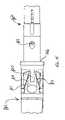
- FIG. 1shows an overall perspective view of the contact portion of the modular connector system of the present invention.
- FIG. 2is an inverted cross-sectional view of the contact of the modular connector shown in FIG. 1 , taken along its longitudinal axis.
- FIG. 3Ais a perspective view of the modular connector including the contact of FIG. 1 and body contained within the shell and with the connector shutter in the closed position.
- FIG. 3Bis a perspective view of the modular connector including the contact of FIG. 1 and body contained within the shell and with the shutter in an intermediate open position.
- FIG. 3Cis an exploded view of the modular connector showing the contact, shutter door, shutter door springs and housing.
- FIG. 4Ais a cross-sectional view of the modular connector containing the modular contact of FIG. 3A taken along its longitudinal axis and showing the shutter in the closed position.
- FIG. 4Bis a cross-sectional view of the modular connector containing the modular contact of FIG. 3B taken along its longitudinal axis and showing the shutter in an intermediate, open shutter position.
- FIG. 5is a perspective view of the adapter for the modular connector of FIG. 3 showing the openings at each end for receiving a modular connector in each opening.
- FIG. 6is an exploded view of the adapter of FIG. 5 and the shutters with their respective cams and the s-spring normally contained therein.
- the shellis shown as removed. The shell serves to hold the various parts of the adapter together and provides EMI shielding.
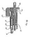
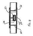
- FIG. 7is a cross-sectional view of the adapter shown in FIG. 5 taken along its longitudinal axis with both shutters in the closed position, and showing the barrel with the alignment sleeve inside.
- FIG. 7Ais a longitudinal cross-sectional view of the modular connector/adapter system showing a modular connector fully inserted into one end of the adapter and the ferrule received within the alignment sleeve.
- FIG. 8is a perspective view of the zero plug rotation embodiment of the modular contact intended for use particularly in angled physical contact (“APC”) environments.
- FIG. 8Ais a perspective view of a second embodiment of the zero plug rotation embodiments providing for an additional degree of freedom.
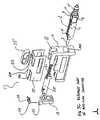
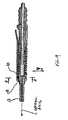
- FIG. 9is a longitudinal cross-sectional view of the zero plug rotation modular contact embodiment of FIG. 8 .
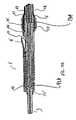
- FIG. 9Ais a longitudinal cross-sectional view of the zero plug rotation modular contact embodiment of FIG. 8 with the plug extender in its initial position extending out beyond the nipple, before finishing and insertion of the optic fiber.
- FIG. 9Bis a longitudinal cross-sectional view of the zero plug rotation modular contact embodiment of FIG. 8 with the plug extender in its final position abutting the ferrule after the contact is terminated so as to insert the optic fiber through the plug extender and ferrule.
- FIG. 10is an inverted, transverse cross-sectional view of the zero plug rotation modular contact embodiment of FIG. 8 taken along section A-A of FIG. 9 , inverted and viewed in the direction of the arrows, showing the modular contact.
- FIG. 10Ais a perspective view of the tuning tool showing the handle, metal insert and gripping end.
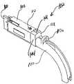
- FIG. 11shows an overall perspective view of the miniature adapter of the push-push embodiment of the invention.
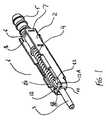
- FIG. 12shows an overall perspective view of the miniature connector with its shutter in the closed position.
- FIG. 13is a partially exploded view of the miniature adapter including both push-push mechanisms and both shutters.
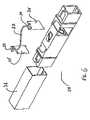
- FIG. 14shows an overall perspective view of the miniature connector partially inserted into the miniature adapter (the adapter shell 118 is removed).
- FIG. 14Ais an overall perspective view of the miniature adapter with locking spacer 140 prior to engagement with the connector.
- FIG. 15is a top view of the miniature adapter and miniature connector when connector 107 is partially inserted into adapter 101 and the adapter shell 118 is removed.
- FIG. 16Ais an isometric view and FIG. 16B is a bottom view of flipper 115 (see FIG. 13 and FIG. 15 ).
- FIG. 17(from a to f) is a schematic view which shows different positions of flipper 115 of the adapter and dual pin 112 of the connector during the push-push insertion and withdrawal action.
- FIG. 18is a perspective view of the simplified connector/adapter system 250 showing two universal modular contacts 251 contained and engaged within body 252 .
- FIG. 19is an exploded view of the simplified connector/adapter system 250 showing universal modular contacts 251 , alignment sleeve 254 , barrel 253 and body 252 .
- FIG. 20is a longitudinal cross-sectional view of FIG. 18 showing the simplified connector/adapter system 250 with modular contacts 251 engaged within body 252 .
- FIG. 1shows the modular contact assembly 1 .
- Modular contact assemblycan be used in either: the modular connector embodiment of FIGS. 3A-3C ; the connector/adapter system embodiment of FIG. 7A ; the push-push connector/adapter system embodiment of FIGS. 12-17F ; and the simplified connector/adapter system body embodiment 250 of FIGS. 18-20 herein.
- This assembly of FIG. 1has an outer shell 2 which serves as a holder for the ferrule plug comprising spring loaded ferrule 3 and ferrule holder 3 A, spring 4 , and rear nipple 5 .
- shell 2is made of metal, though use of other rigid materials should be contemplated as being within the scope of the invention.
- Nipple 5should be maintained steady in the position shown in FIG. 1 , without rotation or axial movement thereof, for optimum performance.
- a holder in the form of flats 6are provided on flanges 8 of the nipple and slots 7 are provided on the outer shell. Flanges 8 protrude into slots 7 , thereby preventing axial movement of nipple 5 relative to shell 2 .
- Flats 6contact flat bed 9 of the outer shell 2 (see FIG. 2 ), thereby further preventing rotation of nipple 5 .
- Ferrule 3also should be prevented from rotating while being spring loaded in the idle position and while in the working position.
- two ears 10are provided on the front end of the outer shell 2 , as shown in FIG. 1 .
- Spring 4which in this embodiment is a coil spring, tends to bias ferrule 3 forward from the nipple 5 to the ears 10 .
- outer shell 2is provided with four limiters 11 and ferrule holder 3 A has a flange 12 with four flats.
- Other operative combinations of shell limiters 11 and numbers of flats on flange 12should be considered as being within the scope of the invention.
- This configurationallows ferrule 3 to move axially, along its longitudinal axis, when in contact with another ferrule but does not allow ferrule 3 to rotate relative to the optical axis (shown in FIG. 9 a ).
- the described configurationallows ferrule 3 to be retracted by being pressed axially backward toward stationary nipple 5 (as viewed in FIG. 1 ) into the interior 76 of outer shell 2 , so as to overcome the outward biasing force provided by compression spring 4 . If ferrule 3 is pushed far enough axially backward so as to be disengaged from the limiters 11 , ferrule 3 can be rotated (in this case in 90° increments to a total of four different positions) wherein different flats of flange 12 would be brought into contact with limiters 11 , using a suitable tuning tool (shown in FIG. 10A ).
- Tunabilityis thereby provided by enabling ferrule 3 to be rotated in this example, to three different radial positions (beyond the original position) that could potentially provide a better end-to-end connection between the ferrules being connected.
- ferrule 3can be retracted from engagement of flats 12 from limiters 11 and rotated in 120 degree increments to two other radial positions.
- ferrule 3is released and pushed forward by the spring 4 to return to the working position with the front of flange 12 in contact with fingers 10 .
- FIG. 2is an inverted cross sectional view of the modular contact 1 with what is normally its bottom side shown on top.
- a plug extender 13which is normally used to aid in injecting epoxy or any other appropriate glue into the interior of the central bore of ferrule 3 to fix the fiber in it.
- plug extenderslides within the central bore of ferrule holder 3 A from the extended position of FIG. 9A to the position of FIG. 2 which would be the final position of plug extender 13 after terminating contact 1 on to fiber optic cable (not shown in FIG. 2 but shown in FIG. 9B ). Also shown in FIG.
- FIG. 2On the nipple 5 are three circular teeth 14 which are used for enhancing crimping reliability, while terminating contact 1 onto fiber optical cable. Also shown in FIG. 2 is latch 15 which serves to secure modular contact 1 into modular connector 17 (as shown in FIGS. 3A and 3B ).
- FIG. 3Ais a perspective view of the modular connector 17 with shutter 18 spring mounted on horizontal shaft 24 in a closed position.
- Modular connector 17consists of the above-described modular contact 1 , body 19 , shutter 18 with the torsion spring 20 and compression spring 21 (see FIGS. 4A and 4B ), outer shell 22 with the latch 23 , shaft 24 for the shutter 18 (see FIGS. 4A and 4B ), and releasing knob 25 .
- Shutter 18is normally biased into the closed position by torsion spring 20 .
- FIG. 3Bis a perspective view of modular connector 17 with shutter 18 in an intermediate open position.
- the shutter 18hits the adapter entrance 29 by its asymmetrical prong 26 (see FIG. 3A ) and rotates upward from the closed position of FIG. 3A into the intermediate, horizontal position shown in FIG. 3B .
- shutter 18slides back into the body 19 with prong 26 protruding upwardly from and sliding along slot 50 A (see FIG.
- shutter 18opens access to the ferrule assembly 3 (see FIG. 1 ) so that ferrule assembly 3 can be engaged in operable physical end-to-end contact with an identical second modular connector (not shown) that is introduced into adapter 28 from the opposite side.
- This retraction process of shutter 18is shown in FIG. 4B .
- the knob 25is pushed down, so that the latch 23 is prompted to lay substantially horizontally and connector 17 is thereby released from engagement with the adapter 28 and pushed slightly apart from the adapter 28 , by two springs: 1) shutter compression spring 21 (see FIG. 4A ); and, 2) compression spring 4 (see FIG. 1 ).
- Compression spring 4has four compressed positions: first, this spring is slightly compressed when assembled into the outer shell 2 ; second, this spring is compressed more when modular contact 1 is assembled into connector body 19 (ferrule 3 is spring loaded by contact of its end surface 16 against the fixed internal surface 27 of the body 19 ); third, compression spring 4 is compressed even more to the working level, when modular connector 17 is engaged in physical contact with identical connector (not shown) inside of the adapter 28 ; and, finally, compression spring 4 can be compressed almost to a solid state when ferrule 3 is pushed back during the tuning procedure.
- FIG. 3Cis an exploded view of modular connector 17 . It shows modular contact 1 which is inserted into connector body 19 through opening 19 A.
- Shutter door 18is rotatably mounted on shaft 24 and biased downward by torsion spring 20 into a closed position. Shaft 24 is held by carriage 21 A carrying compression spring 21 so as to bias shutter door 18 outward, as it retracts, spring 21 becomes compressed and shutter door 18 rotates upward to a horizontal position and moves linearly towards back end B of body 19 .
- Prong 26can then slide along slot 50 A when shutter door 18 is in the horizontal position until it reaches end 51 A.
- Knob 25is positioned to depress latch 23 of shell 22 .
- FIG. 4Ais a cross-sectional view of modular connector 17 with shutter 18 in the closed position.
- Compression spring 21urges shutter 18 outward from end B of body 19 .
- Torsion spring 20urges shutter 18 radially downward about horizontally mounted shaft 24 .
- FIG. 4Bis a cross-section view of the modular connector 17 . It shows shutter 18 in an intermediate open position. In this position connector 17 would not yet be fully inserted into the adapter (not shown). Also it shows latch 15 which keeps modular contact 1 fully engaged and spring loaded in the body 19 of the modular connector 17 . Free end 15 A of latch 15 (see, FIG. 4B ) contacts flange 15 B to prevent modular contact 1 from being withdrawn from body 19 . However, if latch 15 is pushed upward as viewed in FIG. 4B , it will clear the top of flange 15 B and thereby enable retraction of modular contact 1 from body 19 . It also shows latch 23 which can be pressed down by the knob 25 in order to disengage modular connector 17 from the adapter 28 when coupled (not shown).
- FIG. 5shows adapter 28 with two apertures 29 and 30 at its ends, where two modular connectors 17 (See, FIG. 3A ) are intended to be inserted. It also shows outer shell 31 which serves as a holder and a cover of all the internal parts as well as an EMI shield.
- FIG. 6shows adapter 28 in exploded view with shutters 35 and 36 , outer shell 31 and spring 32 removed. It also shows the S-shaped spring 32 which outwardly biases two cams 33 and 34 , each of which is respectively attached to ends of vertically mounted shutters 35 and 36 (see FIG. 7 ). Shutters 35 and 36 , in this example each have a vertical axis of rotation.
- FIG. 7is a cross-sectional view of the adapter 28 of FIG. 5 . It shows the two shutters 35 and 36 in closed position. It also shows barrel 37 with alignment sleeve 38 contained inside. Alignment sleeve 38 can to some extent freely float inside of the barrel 37 , so it can optimally align two ferrules 3 (not shown) being engaged in physical, end-to-end contact from two opposite sides of the adapter.
- FIG. 20shows two such ferrules in end-to-end contact within alignment sleeve 54 within barrel 53 .
- FIG. 7Ais a longitudinal cross-section of the modular connector/adapter system, with modular connector 17 shown fully inserted into one end of the adapter 28 .
- Ferrule 3is received within alignment sleeve 38 floating within barrel 37 of adapter 28 .
- shutter 18is fully retracted and spring 21 is fully compressed within passage 52 A.
- Shutter door 35 of adapter 28is shown closed because no modular connector has been inserted in end 30 . Insertion of modular connector in opposite end 29 of adapter 28 has resulted in automatic retraction of shutter door 18 into passage 52 A and opening of adapter shutter door 36 (not shown).
- Modular connector 17has been latched to adapter 28 because latch 23 has been captured within chamber 23 B and contacts end wall 23 A of chamber 23 B—thereby preventing withdrawal of connector 17 from adapter 28 .
- knob 25is pushed downward (when viewed in FIG. 7A ) sufficiently to enable latch 23 to clear the bottom surface of endwall 23 A. The connector 17 can then be pulled to the right (as viewed in FIG. 7A ) and removed from engagement with adapter 28 .
- FIG. 8shows another embodiment of the modular contact assembly 1 .
- This embodimentis well suited for the APC (“angled physical contact”) version of the universal modular contact.
- APCangled physical contact
- the modular contact assembly 1 shown in FIG. 8has differences as compared to the same assembly shown in FIG. 1 .
- This assemblyhas similar outer metal shell 2 with two slots 39 .
- Insert 40as shown in FIG. 10 , can move freely in those slots in the Y (vertical) direction limited by the internal aperture of the connector body 19 (see FIG. 3 ).
- the square flange 12 of the ferrule 3can move freely in the X (horizontal) direction inside of the rectangular aperture 41 of the insert 40 shown in FIG. 10 .
- the rest of the universal modular contact 1is comparable to the contact shown and described with respect to FIG. 1 .
- FIG. 8 ashows another embodiment of the universal modular contact with zero plug rotation.
- Insert 49has two pins 50 on the opposite sides. Those pins can move up and down in the slots 39 (Y direction as viewed in FIG. 10 ). At the same time insert 49 can slightly rotate around the axis of the pins 50 . It gives ferrule 3 one more degree of freedom, but still maintains zero plug rotation around the optical axis (see FIG. 9 ).
- FIG. 9shows insert 40 and flange 12 of the ferrule 3 in the intermediate position so that it can slightly move up or down in Y (vertical) direction.
- FIG. 9Ashows plug extender 13 (see also FIG. 2 ) only partially inserted into metal holder 42 of the ferrule 3 . This is an intermediate position which changes when universal modular contact 1 is terminated onto the cable 48 (see FIG. 9 b ). Hence, extender 13 slides within contact 1 until it reaches the stop 42 A created by the end of ferrule 3 so that the fragile junction between fiber 44 and plug extender 13 is not exposed outside of the plug body.
- FIG. 9 bshows the universal modular contact 1 terminated onto the cable 48 . It also shows the plug extender 13 fully inserted into the ferrule holder 42 up to stop 42 A. In addition, buffer 43 touches the end 13 A of the plug extender 13 so that fiber 44 is not exposed in an unsupported position which would be prone to breakage. Furthermore it shows the crimping tubing 45 which holds Kevlar® liner 46 and jacket 47 relatively immovable relative to the nipple 5 .
- FIG. 10shows an inverted section A-A of the universal contact shown on FIG. 9 .
- insert 40is shown in the intermediate position inside of two slots 39 of the outer shell 2 .
- Insert 40can move in Y direction (in this case, vertical direction) for the distance+/ ⁇ Y and consequently drag ferrule 3 by its flange 12 in the same direction and distance.
- Flange 12 of the ferrule 3can also move inside of the rectangular aperture of the insert 40 in X direction for the distance+/ ⁇ X.
- ferrule 3can move in both the X and Y directions while not being allowed to rotate around the optical axis (see FIG. 9 ).
- FIG. 10Ashows the tuning tool comprising handle 70 and metal insert 71 with gripping end 72 for grabbing, pushing and turning the ferrule.
- the present inventionenables the use of ultra-small, sub-millimeter ferrule diameters that decrease the system size.
- FIG. 11shows the miniature “push-push” version of adapter 101 .
- This adapterhas an outer shell 102 which serves as a holder for the adapter housing 103 comprising two push-push insertion-withdrawal mechanisms (see FIG. 14 ) and has latch 104 , two stoppers 105 , and two apertures 106 (only one is shown) for two connectors 107 (see FIG. 14 ).
- outer shell 102is made of metal, though use of other rigid materials is contemplated as being within the scope of the invention.
- Housing 103is made from plastic though use of other rigid materials (including cast metal) is contemplated as being within the scope of the invention.
- FIG. 12shows miniature connector 107 for use with the “push-push” adapter shown on FIG. 11 .
- This connectorhas an outer shell 108 , front shutter 109 , boot 110 for fiber optic cable (not shown), connector housing 111 , and a dual pin 112 for interaction with the push-push mechanism of adapter 101 (see FIG. 11 ).
- outer shell 108is made of metal, though use of other rigid materials is contemplated as being within the scope of the invention.
- Housing 111is made from plastic though use of other rigid materials (including cast metal) is contemplated as being within the scope of the invention.
- Boot 110is made from substantially rigid plastic, though use of other rigid material (including hard durometer rubber) is contemplated as being within the scope of the invention.
- Boot 110has a tab 110 a which can be pressed to actuate the push-push interconnection mechanism with a suitable stylus-like member such as the tip of a pen, a PDA stylus, the end of a paperclip or the like in order to engage connector 107 with adapter 101 .
- Dual pin 112has an upper portion that is substantially circular in cross-section ( FIG. 14 ) and a lower portion substantially square in cross-section ( FIG. 17 ).
- FIG. 13shows a partially exploded view of miniature push-push adapter 101 (see FIG. 11 ).
- two push-push mechanisms 113are shown near each of the apertures 106 .
- Each mechanism 113consists of triple prong spring clip 114 , flipper 115 , and nest 116 which serves as a vertical axis about which the flipper 115 rotates or pivots.
- dual shutter mechanism 117 and its cover 118are also shown in FIG. 13 .
- FIG. 13further shows adapter 101 in partially exploded view. It also shows the S-shaped spring 161 which outwardly biases two cams (not shown), each of which is respectively attached to ends of vertically mounted internal shutters (not shown). Shutters in this example each have a vertical axis of rotation.
- Adapteralso contains a barrel containing an alignment sleeve (not shown in FIG. 13 ).
- Alignment sleevecan to some extent freely float inside of the barrel, so it can optimally align two ferrules (not shown in FIG. 13 ) being engaged in physical, end-to-end contact from two opposite sides of the adapter 101 .
- Such end-to-end contact of the ferrulesis shown in FIG. 20 .
- dual pin 112(shown on FIGS. 12 and 14 ) is an integral part of the push-push mechanism, since this dual pin 112 serves as an actuator of the mechanism.
- Each triple prong spring clip 114has two side arms 119 that keep flipper 115 in the middle position in line with the longitudinal axis of the adapter when push-push mechanism is not actuated.
- Triple prong spring clip 114also has a horizontally positioned arm 120 that presses flipper 115 down in order to maintain its constant contact with dual pin 112 (see FIG. 13 ) while performing push-push action during insertion and withdrawal of connector 107 in or out with respect to the adapter 101 .
- FIG. 14shows connector 107 partially inserted into adapter 101 , as shown in FIG. 14 , the omission of cover 102 exposes spring clips 114 having side arms 119 , which serve to keep flippers 115 in the middle position, as shown in FIG. 14 , until connector 107 is inserted far enough into adapter 101 that flipper 115 captures the square portion of pin 112 so as to retain connector 107 therewithin in engaged relation with adapter 101 .
- connector 107into this engaged and retained relationship with adapter 101 can be accomplished by applying force P, as shown in FIG. 14 , to tab 110 A by using a stylus, pen point, paper clip end or the like.
- Notch 140provides clearance for pin 112 and enables proper alignment by receiving and accommodating detent 141 as it moves into the interior 106 of adapter 101 .
- FIG. 14thus shows a perspective view of connector 107 initially, but not fully inserted into adapter 101 (outer shell not shown). This position is the beginning of the push-push process of securing the connector 107 in the mating position within the interior 106 of adapter 101 .
- connector 107is inserted partially (not fully) into opening 106 of one end of adapter 101 . It is not inserted far enough for pin 112 to activate the engagement/disengagement mechanism within interior 106 of adapter 101 .
- spacer clip 140can be inserted between connector 107 and adapter 101 so that notch 142 and cutout region 143 of spacer clip 140 engage connector 107 by receiving detent 141 and body 144 , respectively. That way, because spacer clip 140 prevents connector 107 from being pushed into interior 106 of adapter 101 , unintentional engagement and disengagement of connector 107 and adapter 101 is prevented.
- spacer clip 140To prevent losing spacer clip 140 , it should be loosely attached to connector 107 by wire, rubber band, string, rope, lanyard, filament, Velcro®, or the like (not shown) so that it is readily available when needed, without interfering with its locking function. Likewise, mating fasteners could be used to so attach spacer clip to the connector when not in use to prevent loss.
- FIG. 15shows an enlarged top view of the connector 107 in the process of being inserted into the interior of adapter 101 .
- Dual pin 112has not yet entered adapter interior 106 .
- Side prongs 119are in symmetrical position that keeps flipper 115 substantially in line with the longitudinal axis of the connector/adapter combination.
- Horizontal prong 120presses flipper 115 down. This position is schematically shown on the FIG. 17 a.
- FIG. 16shows flipper 115 in detail.
- FIG. 16 ais an isometric view of the bottom surface of the flipper 115 .
- FIG. 16 bis a bottom view of the flipper 15 .
- FIGS. 16 a and 16 bshow that flipper 115 includes pin 121 providing a vertical axis about which flipper 115 swings or pivots to the left and to the right during the push-push operation.
- Also shownare inclined cam surfaces 124 and 125 of projection 122 and inclined cam surface 126 of projection 123 which urge flipper 115 to swing to the left or to the right based on direct contact with dual pin 112 of the connector 107 , depending upon whether dual pin 112 (see FIG. 14 ) moves forward or backward respectively, during either the insertion or withdrawal operation.
- V-grooved surface 127 of projection 123reliably keeps connector 107 in its mating position by holding squared portion of dual pin 112 with the force of the internal connector spring (not shown).
- Cams 128 and 129facilitate flipper 115 to move over the ramped edges 130 and 131 while the non-ramped opposite vertical sides of those edges 130 and 131 prevent flipper 115 from sliding back and swinging in the wrong direction during insertion or withdrawal of connector 107 into or from adapter 101 .
- pushing force P P1continues to move left in FIG. 17 b until it reaches face 125 of projection 122 which as show in FIG. 17 c acts as a stop, while flipper 115 rotates upwardly about axis X.
- FIGS. 17 a through 17 fschematically show the interaction between flipper 115 and dual pin 112 during insertion and withdrawal of connector 107 into or from adapter 110 .
- arrows F R and F Lrepresent right and left biasing forces created by two side legs 119 of the spring clip 114 (see FIG. 14 ). Those forces tend to keep flipper 115 in the neutral position when inactive.
- Arrows P P1represent the insertion force when connector 107 moves into the adapter 101 during the first “push” action.
- Arrows P Crepresent the force provided by the main connector spring (not shown in FIG. 17 ) which tends to either: (1) keep connector 107 in the mating position with the adapter 101 or, (2) pushes connector 107 out of the interior of adapter 101 after the second “push” action.
- FIGS. 17 a through 17 falso has a virtual 2 mm ruler which shows the relative position of flipper's different elements described earlier and both square and circular elements of dual pin 112 during each step of the insertion and withdrawal processes.
- connectionis initiated by pushing connector 107 in the direction of arrow P P1 of FIG. 17 a , until it is received in opening 106 of adapter 101 ( FIG. 15 ).
- pin 112 of connector 107contacts and then slides along in contact with surface 126 , it is guided along ramped cam surface 128 until it reaches the stopped position ( FIG. 17 c ) by resting against angled surface 125 . Further movement of connector 107 into the interior of adapter 101 is thus prohibited.
- connector 107is again pushed inwardly along the longitudinal axis as viewed in FIGS. 17 e and 17 f and towards the interior of adapter 101 .
- Pin 112is then unseated from the mated position as follows. As inward force P P2 is applied, pin 112 moves up ramped surface 129 and along surface 124 (so that it is no longer captured between surfaces 130 and 127 ) and it slides along surface 131 . Once pin 112 is freed, connector 107 can then be withdrawn from adapter 101 . Because flipper 115 can rotate about axis X, the biasing force F L is overcome and flipper 115 rotates clockwise as viewed in FIGS. 17 e and 17 f.
- FIG. 18shows the simplified version of the modular adapter/connector system 250 wherein modular contacts 251 are retained within body 252 by way of latches 255 trapped within openings 261 . Holes 258 and 259 are provided for facilitated attachment of system 250 to a circuit board or the like.
- the simplified system 250can be used instead of splicing the fibers to be connected.
- the simplified modular adapter/connector system 250includes: barrel 253 which surrounds alignment sleeve 254 in floating fashion. Modular contacts 251 are inserted through ends 270 of body 252 . Ferrules 278 are thereby aligned in end-to-end fashion by alignment sleeve(s) 254 , within barrel 253 . Latches 255 of contacts 251 are captured and retained within openings 261 of body 252 . To retract or withdraw contacts 251 from body 252 , flanges are depressed downwards by a stylus or similar tool, until free ends 255 A clear the bottom of openings 261 so that contacts 251 can be withdrawn from end openings 270 of body 252 .
- ferrules 278 of contacts 251can be seen in aligned and contacting end-to-end fashion within alignment sleeve 254 , and in turn, within barrel 253 and within body 252 .
- Latches 255are biased upwards, so that when connectors 251 are inserted within ends 270 of body 252 and pushed inward along the interior of body 252 , latches 255 will spring upwards into opening 261 of body 252 . So long as end 255 A of latch 255 stays above the bottom of openings 261 , as shown in FIG. 20 , contacts 251 will be securely retained within adapter body 252 .
- latch 255To pull contacts 251 out of body 252 , latch 255 must be pushed downward with a force sufficient to push latch 255 below the bottom of opening 261 to free end 255 A from the sidewall 261 A of opening 261 and thereby enable withdrawal of contacts 251 away from body 252 .
Landscapes
- Physics & Mathematics (AREA)
- General Physics & Mathematics (AREA)
- Optics & Photonics (AREA)
- Mechanical Coupling Of Light Guides (AREA)
Abstract
Description
Claims (25)
Priority Applications (12)
| Application Number | Priority Date | Filing Date | Title |
|---|---|---|---|
| US11/155,360US7261472B2 (en) | 2005-01-12 | 2005-06-17 | Ultra-small, form factor single fiber optical interconnect system, with push-push type insertion/withdrawal mechanism and shuttered modular connector and shuttered adapter and method for using same |
| US11/166,556US7284912B2 (en) | 2005-01-12 | 2005-06-24 | Multi fiber optical interconnect system, with push—push type insertion/withdrawal mechanism, MT-type connector and shuttered adapter and method for using same |
| CA002593819ACA2593819A1 (en) | 2005-01-12 | 2005-10-20 | Ultra-small, form factor single fiber optical interconnect system, with push-push type insertion/withdrawal mechanism and shuttered modular connector and shuttered adapter and method for using same |
| PCT/US2005/038013WO2006076061A2 (en) | 2005-01-12 | 2005-10-20 | Multi fiber optical interconnect system, with push-push type insertion/withdrawal mechanism, mt-type connector and shuttered adapter and method for using same |
| CA002594549ACA2594549A1 (en) | 2005-01-12 | 2005-10-20 | Multi fiber optical interconnect system, with push-push type insertion/withdrawal mechanism, mt-type connector and shuttered adapter and method for using same |
| EP05821042AEP1849031A2 (en) | 2005-01-12 | 2005-10-20 | Multi fiber optical interconnect system, with push-push type insertion/withdrawal mechanism, mt-type connector and shuttered adapter and method for using same |
| JP2007550358AJP4792043B2 (en) | 2005-01-12 | 2005-10-20 | Multi-core optical fiber interconnection system comprising push-push insertion / extraction mechanism, MT connector, and adapter with shutter, and method of use thereof |
| JP2007550359AJP4792044B2 (en) | 2005-01-12 | 2005-10-20 | Ultra-compact form factor single-core optical fiber interconnect system having push-push insertion / extraction mechanism, shutter modular connector and shutter adapter, and method of use thereof |
| EP05820876AEP1849030A2 (en) | 2005-01-12 | 2005-10-20 | Ultra-small, form factor single fiber optical interconnect system, with push-push type insertion/withdrawal mechanism and shuttered modular connector and shuttered adapter and method for using same |
| PCT/US2005/038014WO2006076062A2 (en) | 2005-01-12 | 2005-10-20 | Ultra-small, form factor single fiber optical interconnect system, with push-push type insertion/withdrawal mechanism and shuttered modular connector and shuttered adapter and method for using same |
| JP2011038708AJP5283722B2 (en) | 2005-01-12 | 2011-02-24 | Ultra-compact form factor single-core optical fiber interconnect system having push-push insertion / extraction mechanism, shutter modular connector and shutter adapter, and method of use thereof |
| JP2012282892AJP5559863B2 (en) | 2005-01-12 | 2012-12-26 | Ultra-compact form factor single-core optical fiber interconnect system having push-push insertion / extraction mechanism, shutter modular connector and shutter adapter, and method of use thereof |
Applications Claiming Priority (2)
| Application Number | Priority Date | Filing Date | Title |
|---|---|---|---|
| US3630605A | 2005-01-12 | 2005-01-12 | |
| US11/155,360US7261472B2 (en) | 2005-01-12 | 2005-06-17 | Ultra-small, form factor single fiber optical interconnect system, with push-push type insertion/withdrawal mechanism and shuttered modular connector and shuttered adapter and method for using same |
Related Parent Applications (1)
| Application Number | Title | Priority Date | Filing Date |
|---|---|---|---|
| US3630605AContinuation-In-Part | 2005-01-12 | 2005-01-12 |
Related Child Applications (1)
| Application Number | Title | Priority Date | Filing Date |
|---|---|---|---|
| US11/166,556Continuation-In-PartUS7284912B2 (en) | 2005-01-12 | 2005-06-24 | Multi fiber optical interconnect system, with push—push type insertion/withdrawal mechanism, MT-type connector and shuttered adapter and method for using same |
Publications (2)
| Publication Number | Publication Date |
|---|---|
| US20060153503A1 US20060153503A1 (en) | 2006-07-13 |
| US7261472B2true US7261472B2 (en) | 2007-08-28 |
Family
ID=36653333
Family Applications (1)
| Application Number | Title | Priority Date | Filing Date |
|---|---|---|---|
| US11/155,360Expired - Fee RelatedUS7261472B2 (en) | 2005-01-12 | 2005-06-17 | Ultra-small, form factor single fiber optical interconnect system, with push-push type insertion/withdrawal mechanism and shuttered modular connector and shuttered adapter and method for using same |
Country Status (2)
| Country | Link |
|---|---|
| US (1) | US7261472B2 (en) |
| JP (4) | JP4792044B2 (en) |
Cited By (33)
| Publication number | Priority date | Publication date | Assignee | Title |
|---|---|---|---|---|
| US20080273837A1 (en)* | 2007-05-04 | 2008-11-06 | Mark Margolin | Super miniature, single fiber optical interconnect system with parallel slider push-push type insertion/withdrawal mechanism and method for using same |
| US20090046981A1 (en)* | 2007-08-13 | 2009-02-19 | Illum Technologies, Inc. | High density fiber optic interconnect system with push-release mechanism and method for using same |
| US20090297159A1 (en)* | 2006-08-31 | 2009-12-03 | Optogig, Inc. | High density active modular optoelectronic device for use with push-release mechanism and method for using same |
| US8186890B2 (en) | 1997-05-20 | 2012-05-29 | Adc Telecommunications, Inc. | Fiber connector and adapter |
| US9196997B2 (en) | 2011-11-10 | 2015-11-24 | Panduit Corp. | Shuttered LC adapter |
| US20150362678A1 (en)* | 2013-01-29 | 2015-12-17 | Tyco Electronics Raychem Bvba | Fiber optic connection system |
| US9448369B1 (en)* | 2015-04-28 | 2016-09-20 | Senko Advanced Components, Inc. | Ingress protected optical fiber connector having small diameter (mini-IP connector) |
| US9494746B2 (en) | 2011-11-10 | 2016-11-15 | Panduit Corp. | Shuttered LC adapter |
| US20170045695A1 (en)* | 2015-04-28 | 2017-02-16 | Senko Advanced Components, Inc. | Ingress Protected Optical Fiber Connector Having Small Diameter (Mini-IP Connector) |
| US20190250344A1 (en)* | 2017-07-14 | 2019-08-15 | Senko Advanced Components Inc. | Ultra-small form factor optical connectors |
| US10845547B2 (en)* | 2016-07-08 | 2020-11-24 | Huber+Suhner Ag | Optical connector having pivotable cap protecting ferrule |
| US11150429B2 (en)* | 2018-05-11 | 2021-10-19 | Clearfield, Inc. | Optical fiber distribution cabinet |
| US11215768B2 (en) | 2017-06-28 | 2022-01-04 | Corning Research & Development Corporation | Fiber optic connectors and connectorization employing adhesive admitting adapters |
| US11300746B2 (en) | 2017-06-28 | 2022-04-12 | Corning Research & Development Corporation | Fiber optic port module inserts, assemblies and methods of making the same |
| US11454766B2 (en) | 2017-11-17 | 2022-09-27 | Senko Advanced Components, Inc. | Ultra-small form factor optical connector having dual alignment keys |
| US11585989B2 (en) | 2017-07-14 | 2023-02-21 | Senko Advanced Components, Inc. | Small form factor fiber optic connector with multi-purpose boot |
| US11604320B2 (en) | 2020-09-30 | 2023-03-14 | Corning Research & Development Corporation | Connector assemblies for telecommunication enclosures |
| US11650388B2 (en) | 2019-11-14 | 2023-05-16 | Corning Research & Development Corporation | Fiber optic networks having a self-supporting optical terminal and methods of installing the optical terminal |
| US11668890B2 (en) | 2017-06-28 | 2023-06-06 | Corning Research & Development Corporation | Multiports and other devices having optical connection ports with securing features and methods of making the same |
| US11686913B2 (en) | 2020-11-30 | 2023-06-27 | Corning Research & Development Corporation | Fiber optic cable assemblies and connector assemblies having a crimp ring and crimp body and methods of fabricating the same |
| US11703646B2 (en) | 2017-06-28 | 2023-07-18 | Corning Research & Development Corporation | Multiports and optical connectors with rotationally discrete locking and keying features |
| US11822133B2 (en) | 2017-07-14 | 2023-11-21 | Senko Advanced Components, Inc. | Ultra-small form factor optical connector and adapter |
| US11880076B2 (en) | 2020-11-30 | 2024-01-23 | Corning Research & Development Corporation | Fiber optic adapter assemblies including a conversion housing and a release housing |
| US11886010B2 (en) | 2019-10-07 | 2024-01-30 | Corning Research & Development Corporation | Fiber optic terminals and fiber optic networks having variable ratio couplers |
| US11927810B2 (en) | 2020-11-30 | 2024-03-12 | Corning Research & Development Corporation | Fiber optic adapter assemblies including a conversion housing and a release member |
| US11947167B2 (en) | 2021-05-26 | 2024-04-02 | Corning Research & Development Corporation | Fiber optic terminals and tools and methods for adjusting a split ratio of a fiber optic terminal |
| US11994722B2 (en) | 2020-11-30 | 2024-05-28 | Corning Research & Development Corporation | Fiber optic adapter assemblies including an adapter housing and a locking housing |
| US12001064B2 (en) | 2017-07-14 | 2024-06-04 | Senko Advanced Components, Inc. | Small form factor fiber optic connector with multi-purpose boot |
| US12019279B2 (en) | 2019-05-31 | 2024-06-25 | Corning Research & Development Corporation | Multiports and other devices having optical connection ports with sliding actuators and methods of making the same |
| US12038613B2 (en)* | 2019-03-28 | 2024-07-16 | Senko Advanced Components, Inc. | Behind-the-wall optical connector and assembly of the same |
| US12265264B2 (en) | 2019-07-26 | 2025-04-01 | Commscope Technologies Llc | Fiber optic adapters convertible between different polarity types |
| US12271040B2 (en) | 2017-06-28 | 2025-04-08 | Corning Research & Development Corporation | Fiber optic extender ports, assemblies and methods of making the same |
| US12372727B2 (en) | 2020-10-30 | 2025-07-29 | Corning Research & Development Corporation | Female fiber optic connectors having a rocker latch arm and methods of making the same |
Families Citing this family (67)
| Publication number | Priority date | Publication date | Assignee | Title |
|---|---|---|---|---|
| US20070003288A1 (en)* | 2005-06-30 | 2007-01-04 | Xiaolin Tong | Bidirectional HDCP transmission module using single optical fiber |
| US20070242062A1 (en)* | 2006-04-18 | 2007-10-18 | Yong Guo | EDID pass through via serial channel |
| US7386641B2 (en)* | 2006-04-18 | 2008-06-10 | Owlink Technology, Inc. | Protocol for uncompressed multimedia data transmission |
| US20070280282A1 (en)* | 2006-06-05 | 2007-12-06 | Tzeng Shing-Wu P | Indoor digital multimedia networking |
| US20070292135A1 (en)* | 2006-06-09 | 2007-12-20 | Yong Guo | Integrated remote control signaling |
| US8032021B2 (en)* | 2007-02-28 | 2011-10-04 | Finisar Corporation | Status link for multi-channel optical communication systems |
| US8861952B2 (en)* | 2007-02-28 | 2014-10-14 | Finisar Corporation | Redundancy and interoperability in multi-channel optoelectronic devices |
| US8526810B2 (en)* | 2007-04-30 | 2013-09-03 | Finisar Corporation | Eye safety and interoperability of active cable devices |
| US8150261B2 (en) | 2007-05-22 | 2012-04-03 | Owlink Technology, Inc. | Universal remote control device |
| US7400801B1 (en) | 2007-06-19 | 2008-07-15 | Owlink Technology, Inc. | Bidirectional HDCP module using single optical fiber and waveguide combiner/splitter |
| US7901144B2 (en)* | 2008-03-14 | 2011-03-08 | Finisar Corporation | Optical interconnect solution |
| US7806602B2 (en)* | 2008-03-14 | 2010-10-05 | Finisar Corporation | Optical micro-connector |
| JP5324910B2 (en)* | 2008-11-27 | 2013-10-23 | アダマンド工業株式会社 | Optical connector |
| US8982455B2 (en)* | 2009-09-22 | 2015-03-17 | Intelligent Imaging Innovations, Inc. | Modular design of a scanning microscope attachment and accessories |
| US8634131B2 (en) | 2009-12-14 | 2014-01-21 | Intelligent Imaging Innovations, Inc. | Spherical aberration correction for non-descanned applications |
| CN102116909B (en)* | 2010-01-04 | 2012-09-05 | 泰科电子(上海)有限公司 | Safety device for optical fiber adapter interface |
| CN102236130B (en)* | 2010-04-28 | 2013-12-11 | 鸿富锦精密工业(深圳)有限公司 | Optical fiber connector |
| WO2011160310A1 (en)* | 2010-06-25 | 2011-12-29 | 深圳日海通讯技术股份有限公司 | Optical fiber plug for high density optical fiber connections |
| CN102401940B (en)* | 2010-09-08 | 2014-12-10 | 深圳日海通讯技术股份有限公司 | Multicore optical fiber connector |
| US11493701B2 (en) | 2010-10-22 | 2022-11-08 | Panduit Corp. | Optical communications connectors |
| US8636424B2 (en) | 2010-10-22 | 2014-01-28 | Panduit Corp. | Optical communication connector |
| CN103018843B (en)* | 2011-09-23 | 2015-05-20 | 泰科电子(上海)有限公司 | Optical fiber connector plug |
| CN103018844B (en)* | 2011-09-23 | 2014-10-15 | 泰科电子(上海)有限公司 | Optical fiber connector plug |
| CN104040395B (en) | 2012-01-06 | 2016-06-01 | 惠普发展公司,有限责任合伙企业 | Optics is connected to the connector modules of electronic installation |
| MX338075B (en)* | 2012-02-07 | 2016-04-01 | Tyco Electronics Corp | Optical fiber connection system including optical fiber alignment device. |
| JP6092581B2 (en)* | 2012-11-08 | 2017-03-08 | 三和電気工業株式会社 | Optical connector plug |
| JP6400892B2 (en)* | 2013-09-17 | 2018-10-03 | 三和電気工業株式会社 | LC type optical connector adapter with built-in dustproof shutter |
| US9798092B2 (en)* | 2013-09-30 | 2017-10-24 | Hewlett Packard Enterprise Development Lp | Optical blind-mate connector and adapter |
| CN109343178A (en)* | 2014-02-07 | 2019-02-15 | 泰科电子公司 | Hardened optical power connection system |
| CN103885129B (en)* | 2014-03-17 | 2016-01-20 | 深圳日海通讯技术股份有限公司 | A kind of joints of optical fibre |
| WO2015144883A1 (en) | 2014-03-28 | 2015-10-01 | Tyco Electronics Raychem Bvba | Fiber optic connection system |
| US20150292669A1 (en)* | 2014-04-14 | 2015-10-15 | Engineered Network Systems | Lockable Tablet Stand |
| WO2016068892A1 (en)* | 2014-10-29 | 2016-05-06 | Hewlett Packard Enterprise Development Lp | Optical connector assembly apparatus |
| CN204441611U (en)* | 2015-01-23 | 2015-07-01 | 昆山合真和光电科技有限公司 | There is the SFP connector of snap close and release mechanism |
| US11022760B2 (en)* | 2015-04-29 | 2021-06-01 | Nlight, Inc. | Portable industrial fiber optic inspection scope |
| CN105242356B (en)* | 2015-08-31 | 2017-08-04 | 中航光电科技股份有限公司 | A socket and connector assembly |
| DE102016006141A1 (en)* | 2016-05-18 | 2017-11-23 | Dätwyler Cabling Solutions Ag | Coupling part for optical waveguides and associated coupling method |
| CN110998398B (en)* | 2017-06-28 | 2022-09-06 | 康宁研究与开发公司 | Fiber extender port, assembly and method of making same |
| EP3646086A1 (en)* | 2017-06-28 | 2020-05-06 | Corning Research & Development Corporation | Fiber optic connectors |
| US11187859B2 (en) | 2017-06-28 | 2021-11-30 | Corning Research & Development Corporation | Fiber optic connectors and methods of making the same |
| EP3652573A1 (en)* | 2017-07-14 | 2020-05-20 | Huber+Suhner AG | Optical connector assembly comprising a shutter |
| US10718911B2 (en) | 2017-08-24 | 2020-07-21 | Senko Advanced Components, Inc. | Ultra-small form factor optical connectors using a push-pull boot receptacle release |
| JP7177147B2 (en)* | 2017-09-20 | 2022-11-22 | モレックス エルエルシー | Light blocking shutter for fiber optic adapter |
| US11002923B2 (en) | 2017-11-21 | 2021-05-11 | Senko Advanced Components, Inc. | Fiber optic connector with cable boot release having a two-piece clip assembly |
| US10712512B2 (en) | 2017-11-21 | 2020-07-14 | Senko Advanced Components, Inc | Fiber optic connector assemblies with cable boot release |
| US11016250B2 (en)* | 2017-12-19 | 2021-05-25 | Us Conec, Ltd. | Mini duplex connector with push-pull polarity mechanism, carrier, and rail-receiving crimp body |
| US11073664B2 (en) | 2018-08-13 | 2021-07-27 | Senko Advanced Components, Inc. | Cable boot assembly for releasing fiber optic connector from a receptacle |
| US10921531B2 (en) | 2018-09-12 | 2021-02-16 | Senko Advanced Components, Inc. | LC type connector with push/pull assembly for releasing connector from a receptacle using a cable boot |
| WO2020055440A1 (en) | 2018-09-12 | 2020-03-19 | Senko Advanced Componetns, Inc. | Lc type connector with clip-on push/pull tab for releasing connector from a receptacle using a cable boot |
| US10921530B2 (en) | 2018-09-12 | 2021-02-16 | Senko Advanced Components, Inc. | LC type connector with push/pull assembly for releasing connector from a receptacle using a cable boot |
| TWM572465U (en)* | 2018-09-18 | 2019-01-01 | 大陸商深圳望得源科技有限公司 | The optical fiber connector |
| US10545295B1 (en)* | 2018-10-22 | 2020-01-28 | Sanwa Denki Kogyo Co., Ltd. | Optical adapter with shutter |
| US10641967B1 (en) | 2018-11-16 | 2020-05-05 | Corning Research & Development Corporation | Multiport assemblies including a modular adapter support array |
| US10768382B2 (en) | 2018-11-29 | 2020-09-08 | Corning Research & Development Corporation | Multiport assemblies including access apertures and a release tool |
| PT3903136T (en) | 2018-12-28 | 2024-12-05 | Corning Res & Dev Corp | Multiport assemblies including mounting features or dust plugs |
| US11340406B2 (en) | 2019-04-19 | 2022-05-24 | Senko Advanced Components, Inc. | Small form factor fiber optic connector with resilient latching mechanism for securing within a hook-less receptacle |
| USD916138S1 (en)* | 2019-04-19 | 2021-04-13 | Cummins Emission Solutions Inc. | Routing guide |
| US12061366B2 (en) | 2019-05-17 | 2024-08-13 | Commscope Technologies Llc | Mechanical connection interface |
| WO2020252355A1 (en) | 2019-06-13 | 2020-12-17 | Senko Advanced Components, Inc | Lever actuated latch arm for releasing a fiber optic connector from a receptacle port and method of use |
| US11294133B2 (en) | 2019-07-31 | 2022-04-05 | Corning Research & Development Corporation | Fiber optic networks using multiports and cable assemblies with cable-to-connector orientation |
| US11487073B2 (en) | 2019-09-30 | 2022-11-01 | Corning Research & Development Corporation | Cable input devices having an integrated locking feature and assemblies using the cable input devices |
| US11536921B2 (en) | 2020-02-11 | 2022-12-27 | Corning Research & Development Corporation | Fiber optic terminals having one or more loopback assemblies |
| US11635576B2 (en)* | 2020-07-24 | 2023-04-25 | Senko Advanced Components, Inc. | Ferrule sub-assembly for a fiber optic connector |
| CN113534373B (en)* | 2021-06-26 | 2022-05-13 | 华为技术有限公司 | Distribution Assemblies, Fiber Optic Distribution Equipment and Fiber Dispatch Systems |
| DE102021134076B3 (en)* | 2021-12-21 | 2023-01-19 | Femotech Gmbh | Coupling for blow-in connectors, fiber optic splice cassette, fiber optic splice box, system for connecting fiber optic cables, and method for laying fiber optic cables |
| CN114594553B (en)* | 2022-03-01 | 2024-07-09 | 南京华脉科技股份有限公司 | Plug-in optical fiber connecting assembly |
| CN115144972B (en)* | 2022-07-18 | 2023-06-20 | 烽火通信科技股份有限公司 | Waterproof and dustproof connector, adapter and connector assembly |
Citations (14)
| Publication number | Priority date | Publication date | Assignee | Title |
|---|---|---|---|---|
| US4726647A (en)* | 1985-03-19 | 1988-02-23 | Sumitomo Electric Industries, Ltd. | Optical connector |
| US5214730A (en) | 1991-05-13 | 1993-05-25 | Nippon Telegraph And Telephone Corporation | Multifiber optical connector plug with low reflection and low insertion loss |
| US5317663A (en)* | 1993-05-20 | 1994-05-31 | Adc Telecommunications, Inc. | One-piece SC adapter |
| US5734778A (en)* | 1994-11-03 | 1998-03-31 | Loughlin; John P. | Variable attenuator connector |
| US5838856A (en) | 1995-10-31 | 1998-11-17 | Daewoo Telecom, Ltd. | Optical-fiber cable connector assembly |
| US6238278B1 (en) | 1996-11-15 | 2001-05-29 | Johannes Haftmann | Ferrule holder and ferrule grinding apparatus |
| US6634796B2 (en)* | 1999-06-30 | 2003-10-21 | Corning Cable Systems Llc | Polarity reversal for fiber optic connections |
| US6695489B2 (en)* | 2000-12-27 | 2004-02-24 | Adc Telecommunications, Inc. | Tunable fiber optic connector and method for assembling |
| US6823109B2 (en) | 2000-03-01 | 2004-11-23 | Nippon Sheet Glass, Co., Ltd. | Optical fiber-lens array |
| US6886990B2 (en) | 2002-05-09 | 2005-05-03 | Seiko Instruments Inc., Nippon | Optical connector |
| US6918704B2 (en) | 2003-01-30 | 2005-07-19 | Panduit Corp. | Tunable fiber optic connector |
| US6934450B2 (en) | 2002-12-10 | 2005-08-23 | Mitsubishi Denki Kabushiki Kaisha | Optical path-changing connector |
| US20050286833A1 (en) | 2001-08-23 | 2005-12-29 | Anne Kramer | Universal adapter |
| US20060067627A1 (en)* | 2004-09-30 | 2006-03-30 | Crews Darren S | Blind mate optical connector |
Family Cites Families (5)
| Publication number | Priority date | Publication date | Assignee | Title |
|---|---|---|---|---|
| JPH10186177A (en)* | 1996-10-28 | 1998-07-14 | Sumitomo Electric Ind Ltd | Optical connector, optical connector connection method, and gripping tool |
| US6102581A (en)* | 1998-06-16 | 2000-08-15 | Lucent Technologies Inc. | Optical adapter including a ferrule assembly |
| DE50009898D1 (en)* | 1999-07-26 | 2005-05-04 | Diamond Sa | Plug part for an optical connector |
| EP1115014A1 (en)* | 2000-01-06 | 2001-07-11 | Diamond SA | Plug portion for an optical connection and its assembly method |
| US6293710B1 (en)* | 1999-10-06 | 2001-09-25 | Lucent Technologies Inc. | Optical connector having a one-piece housing |
- 2005
- 2005-06-17USUS11/155,360patent/US7261472B2/ennot_activeExpired - Fee Related
- 2005-10-20JPJP2007550359Apatent/JP4792044B2/enactiveActive
- 2005-10-20JPJP2007550358Apatent/JP4792043B2/enactiveActive
- 2011
- 2011-02-24JPJP2011038708Apatent/JP5283722B2/enactiveActive
- 2012
- 2012-12-26JPJP2012282892Apatent/JP5559863B2/enactiveActive
Patent Citations (14)
| Publication number | Priority date | Publication date | Assignee | Title |
|---|---|---|---|---|
| US4726647A (en)* | 1985-03-19 | 1988-02-23 | Sumitomo Electric Industries, Ltd. | Optical connector |
| US5214730A (en) | 1991-05-13 | 1993-05-25 | Nippon Telegraph And Telephone Corporation | Multifiber optical connector plug with low reflection and low insertion loss |
| US5317663A (en)* | 1993-05-20 | 1994-05-31 | Adc Telecommunications, Inc. | One-piece SC adapter |
| US5734778A (en)* | 1994-11-03 | 1998-03-31 | Loughlin; John P. | Variable attenuator connector |
| US5838856A (en) | 1995-10-31 | 1998-11-17 | Daewoo Telecom, Ltd. | Optical-fiber cable connector assembly |
| US6238278B1 (en) | 1996-11-15 | 2001-05-29 | Johannes Haftmann | Ferrule holder and ferrule grinding apparatus |
| US6634796B2 (en)* | 1999-06-30 | 2003-10-21 | Corning Cable Systems Llc | Polarity reversal for fiber optic connections |
| US6823109B2 (en) | 2000-03-01 | 2004-11-23 | Nippon Sheet Glass, Co., Ltd. | Optical fiber-lens array |
| US6695489B2 (en)* | 2000-12-27 | 2004-02-24 | Adc Telecommunications, Inc. | Tunable fiber optic connector and method for assembling |
| US20050286833A1 (en) | 2001-08-23 | 2005-12-29 | Anne Kramer | Universal adapter |
| US6886990B2 (en) | 2002-05-09 | 2005-05-03 | Seiko Instruments Inc., Nippon | Optical connector |
| US6934450B2 (en) | 2002-12-10 | 2005-08-23 | Mitsubishi Denki Kabushiki Kaisha | Optical path-changing connector |
| US6918704B2 (en) | 2003-01-30 | 2005-07-19 | Panduit Corp. | Tunable fiber optic connector |
| US20060067627A1 (en)* | 2004-09-30 | 2006-03-30 | Crews Darren S | Blind mate optical connector |
Non-Patent Citations (2)
| Title |
|---|
| HMU Series: MU Type Fiber Optics Connectors, 20 pages. |
| Research at Photonics Laboratories (4-5); MU-type Angled-PC Connector, Copyright 2004, Nippon Telegraph & Telephone Corporation, 1 page. |
Cited By (77)
| Publication number | Priority date | Publication date | Assignee | Title |
|---|---|---|---|---|
| US8186890B2 (en) | 1997-05-20 | 2012-05-29 | Adc Telecommunications, Inc. | Fiber connector and adapter |
| US8870466B2 (en) | 1997-05-20 | 2014-10-28 | Adc Telecommunications, Inc. | Fiber connector and adapter |
| US9383524B2 (en) | 1997-05-20 | 2016-07-05 | Commscope Technologies Llc | Fiber connector and adapter |
| US9250399B2 (en)* | 2006-08-31 | 2016-02-02 | Optogig, Inc. | High density active modular optoelectronic device for use with push-release mechanism and method for using same |
| US20090297159A1 (en)* | 2006-08-31 | 2009-12-03 | Optogig, Inc. | High density active modular optoelectronic device for use with push-release mechanism and method for using same |
| US7806599B2 (en) | 2007-05-04 | 2010-10-05 | Illum Technologies, Inc. | Super miniature, single fiber optical interconnect system with parallel slider push-push type insertion/withdrawal mechanism and method for using same |
| US20080273837A1 (en)* | 2007-05-04 | 2008-11-06 | Mark Margolin | Super miniature, single fiber optical interconnect system with parallel slider push-push type insertion/withdrawal mechanism and method for using same |
| US20090046981A1 (en)* | 2007-08-13 | 2009-02-19 | Illum Technologies, Inc. | High density fiber optic interconnect system with push-release mechanism and method for using same |
| US7717625B2 (en) | 2007-08-13 | 2010-05-18 | Illum Technologies, Inc. | High density fiber optic interconnect system with push-release mechanism and method for using same |
| US9494746B2 (en) | 2011-11-10 | 2016-11-15 | Panduit Corp. | Shuttered LC adapter |
| US9709754B2 (en) | 2011-11-10 | 2017-07-18 | Panduit Corp. | Shuttered LC adapter |
| US10012799B2 (en) | 2011-11-10 | 2018-07-03 | Panduit Corp. | Shuttered LC adapter |
| US9196997B2 (en) | 2011-11-10 | 2015-11-24 | Panduit Corp. | Shuttered LC adapter |
| US20150362678A1 (en)* | 2013-01-29 | 2015-12-17 | Tyco Electronics Raychem Bvba | Fiber optic connection system |
| US9606299B2 (en)* | 2013-01-29 | 2017-03-28 | CommScope Connectivity Belgium BVBA | Fiber optic connection system |
| US9448369B1 (en)* | 2015-04-28 | 2016-09-20 | Senko Advanced Components, Inc. | Ingress protected optical fiber connector having small diameter (mini-IP connector) |
| US20170045695A1 (en)* | 2015-04-28 | 2017-02-16 | Senko Advanced Components, Inc. | Ingress Protected Optical Fiber Connector Having Small Diameter (Mini-IP Connector) |
| US9829654B2 (en)* | 2015-04-28 | 2017-11-28 | Senko Advanced Components, Inc. | Ingress protected optical fiber connector having small diameter (mini-IP connector) |
| US10845547B2 (en)* | 2016-07-08 | 2020-11-24 | Huber+Suhner Ag | Optical connector having pivotable cap protecting ferrule |
| US11287581B2 (en)* | 2017-06-28 | 2022-03-29 | Corning Research & Development Corporation | Compact fiber optic connectors, cable assemblies and methods of making the same |
| US11536913B2 (en) | 2017-06-28 | 2022-12-27 | Corning Research & Development Corporation | Fiber optic connectors and connectorization employing adhesive admitting adapters |
| US12379552B2 (en) | 2017-06-28 | 2025-08-05 | Corning Research & Development Corporation | Compact fiber optic connectors, cable assemblies and methods of making the same |
| US11215768B2 (en) | 2017-06-28 | 2022-01-04 | Corning Research & Development Corporation | Fiber optic connectors and connectorization employing adhesive admitting adapters |
| US12353024B2 (en) | 2017-06-28 | 2025-07-08 | Corning Research & Development Corporation | Multiports and optical connectors with rotationally discrete locking and keying features |
| US11906792B2 (en) | 2017-06-28 | 2024-02-20 | Corning Research & Development Corporation | Compact fiber optic connectors having multiple connector footprints, along with cable assemblies and methods of making the same |
| US11300746B2 (en) | 2017-06-28 | 2022-04-12 | Corning Research & Development Corporation | Fiber optic port module inserts, assemblies and methods of making the same |
| US12353025B2 (en) | 2017-06-28 | 2025-07-08 | Corning Optical Communications LLC | Multiports having a connection port insert and methods of making the same |
| US11409055B2 (en) | 2017-06-28 | 2022-08-09 | Corning Optical Communications LLC | Multiports having connection ports with associated securing features and methods of making the same |
| US11415759B2 (en) | 2017-06-28 | 2022-08-16 | Corning Optical Communications LLC | Multiports having a connection port insert and methods of making the same |
| US12298568B2 (en) | 2017-06-28 | 2025-05-13 | Corning Research & Development Corporation | Fiber optic connectors and multiport assemblies including retention features |
| US11460646B2 (en) | 2017-06-28 | 2022-10-04 | Corning Research & Development Corporation | Fiber optic connectors and multiport assemblies including retention features |
| US12276846B2 (en) | 2017-06-28 | 2025-04-15 | Corning Research & Development Corporation | Compact fiber optic connectors, cable assemblies and methods of making the same |
| US11487065B2 (en) | 2017-06-28 | 2022-11-01 | Corning Research & Development Corporation | Multiports and devices having a connector port with a rotating securing feature |
| US12271040B2 (en) | 2017-06-28 | 2025-04-08 | Corning Research & Development Corporation | Fiber optic extender ports, assemblies and methods of making the same |
| US12379551B2 (en) | 2017-06-28 | 2025-08-05 | Corning Optical Communications LLC | Multiports having connection ports formed in the shell and associated securing features |
| US11579377B2 (en) | 2017-06-28 | 2023-02-14 | Corning Research & Development Corporation | Compact fiber optic connectors, cable assemblies and methods of making the same with alignment elements |
| US12174432B2 (en) | 2017-06-28 | 2024-12-24 | Corning Research & Development Corporation | Fiber optic connectors and connectorization employing adhesive admitting adapters |
| US12092878B2 (en) | 2017-06-28 | 2024-09-17 | Corning Research & Development Corporation | Fiber optic connectors having a keying structure and methods of making the same |
| US11624877B2 (en) | 2017-06-28 | 2023-04-11 | Corning Research & Development Corporation | Multiports having connection ports with securing features that actuate flexures and methods of making the same |
| US12013578B2 (en) | 2017-06-28 | 2024-06-18 | Corning Research & Development Corporation | Multifiber fiber optic connectors, cable assemblies and methods of making the same |
| US11656414B2 (en) | 2017-06-28 | 2023-05-23 | Corning Research & Development Corporation | Multiports and other devices having connection ports with securing features and methods of making the same |
| US11668890B2 (en) | 2017-06-28 | 2023-06-06 | Corning Research & Development Corporation | Multiports and other devices having optical connection ports with securing features and methods of making the same |
| US12429655B2 (en) | 2017-06-28 | 2025-09-30 | Corning Optical Communications LLC | Multiports having connection ports with associated securing features and methods of making the same |
| US11703646B2 (en) | 2017-06-28 | 2023-07-18 | Corning Research & Development Corporation | Multiports and optical connectors with rotationally discrete locking and keying features |
| US11789214B2 (en) | 2017-06-28 | 2023-10-17 | Corning Research & Development Corporation | Multiports and other devices having keyed connection ports and securing features and methods of making the same |
| US11966089B2 (en) | 2017-06-28 | 2024-04-23 | Corning Optical Communications, Llc | Multiports having connection ports formed in the shell and associated securing features |
| US11940656B2 (en) | 2017-06-28 | 2024-03-26 | Corning Research & Development Corporation | Compact fiber optic connectors, cable assemblies and methods of making the same |
| US11914198B2 (en) | 2017-06-28 | 2024-02-27 | Corning Research & Development Corporation | Compact fiber optic connectors having multiple connector footprints, along with cable assemblies and methods of making the same |
| US11914197B2 (en) | 2017-06-28 | 2024-02-27 | Corning Research & Development Corporation | Compact fiber optic connectors having multiple connector footprints, along with cable assemblies and methods of making the same |
| US11886017B2 (en) | 2017-06-28 | 2024-01-30 | Corning Research & Development Corporation | Multiports and other devices having connection ports with securing features and methods of making the same |
| US12001064B2 (en) | 2017-07-14 | 2024-06-04 | Senko Advanced Components, Inc. | Small form factor fiber optic connector with multi-purpose boot |
| US11280972B2 (en) | 2017-07-14 | 2022-03-22 | Senko Advanced Components, Inc. | Ultra-small form factor optical connectors used as part of a reconfigurable outer housing |
| US20190250344A1 (en)* | 2017-07-14 | 2019-08-15 | Senko Advanced Components Inc. | Ultra-small form factor optical connectors |
| US12228774B2 (en) | 2017-07-14 | 2025-02-18 | Senko Advanced Components, Inc. | Ultra-small form factor optical connector and adapter |
| US11822133B2 (en) | 2017-07-14 | 2023-11-21 | Senko Advanced Components, Inc. | Ultra-small form factor optical connector and adapter |
| US11169338B2 (en)* | 2017-07-14 | 2021-11-09 | Senko Advanced Components, Inc. | Ultra-small form factor optical connectors |
| US11809006B2 (en) | 2017-07-14 | 2023-11-07 | Senko Advanced Components, Inc. | Ultra-small form factor optical connectors used as part of a reconfigurable outer housing |
| US11585989B2 (en) | 2017-07-14 | 2023-02-21 | Senko Advanced Components, Inc. | Small form factor fiber optic connector with multi-purpose boot |
| US11307369B2 (en) | 2017-07-14 | 2022-04-19 | Senko Advanced Components, Inc. | Ultra-small form factor optical connectors used as part of a reconfigurable outer housing |
| US11487067B2 (en) | 2017-07-14 | 2022-11-01 | Senko Advanced Components, Inc. | Ultra-small form factor optical connectors |
| US11474315B2 (en) | 2017-07-14 | 2022-10-18 | Senko Advanced Components, Inc. | Ultra-small form factor optical connectors used as part of a reconfigurable outer housing |
| US11454766B2 (en) | 2017-11-17 | 2022-09-27 | Senko Advanced Components, Inc. | Ultra-small form factor optical connector having dual alignment keys |
| US11150429B2 (en)* | 2018-05-11 | 2021-10-19 | Clearfield, Inc. | Optical fiber distribution cabinet |
| US12038613B2 (en)* | 2019-03-28 | 2024-07-16 | Senko Advanced Components, Inc. | Behind-the-wall optical connector and assembly of the same |
| US12019279B2 (en) | 2019-05-31 | 2024-06-25 | Corning Research & Development Corporation | Multiports and other devices having optical connection ports with sliding actuators and methods of making the same |
| US12265264B2 (en) | 2019-07-26 | 2025-04-01 | Commscope Technologies Llc | Fiber optic adapters convertible between different polarity types |
| US11886010B2 (en) | 2019-10-07 | 2024-01-30 | Corning Research & Development Corporation | Fiber optic terminals and fiber optic networks having variable ratio couplers |
| US11650388B2 (en) | 2019-11-14 | 2023-05-16 | Corning Research & Development Corporation | Fiber optic networks having a self-supporting optical terminal and methods of installing the optical terminal |
| US11604320B2 (en) | 2020-09-30 | 2023-03-14 | Corning Research & Development Corporation | Connector assemblies for telecommunication enclosures |
| US12019285B2 (en) | 2020-09-30 | 2024-06-25 | Corning Research & Development Corporation | Connector assemblies for telecommunication enclosures |
| US12372727B2 (en) | 2020-10-30 | 2025-07-29 | Corning Research & Development Corporation | Female fiber optic connectors having a rocker latch arm and methods of making the same |
| US12345927B2 (en) | 2020-11-30 | 2025-07-01 | Corning Research & Development Corporation | Fiber optic adapter assemblies including a conversion housing and a release housing |
| US11686913B2 (en) | 2020-11-30 | 2023-06-27 | Corning Research & Development Corporation | Fiber optic cable assemblies and connector assemblies having a crimp ring and crimp body and methods of fabricating the same |
| US11994722B2 (en) | 2020-11-30 | 2024-05-28 | Corning Research & Development Corporation | Fiber optic adapter assemblies including an adapter housing and a locking housing |
| US11927810B2 (en) | 2020-11-30 | 2024-03-12 | Corning Research & Development Corporation | Fiber optic adapter assemblies including a conversion housing and a release member |
| US11880076B2 (en) | 2020-11-30 | 2024-01-23 | Corning Research & Development Corporation | Fiber optic adapter assemblies including a conversion housing and a release housing |
| US11947167B2 (en) | 2021-05-26 | 2024-04-02 | Corning Research & Development Corporation | Fiber optic terminals and tools and methods for adjusting a split ratio of a fiber optic terminal |
Also Published As
| Publication number | Publication date |
|---|---|
| JP4792044B2 (en) | 2011-10-12 |
| JP4792043B2 (en) | 2011-10-12 |
| US20060153503A1 (en) | 2006-07-13 |
| JP2008527442A (en) | 2008-07-24 |
| JP5559863B2 (en) | 2014-07-23 |
| JP2013057976A (en) | 2013-03-28 |
| JP2011128650A (en) | 2011-06-30 |
| JP2008527443A (en) | 2008-07-24 |
| JP5283722B2 (en) | 2013-09-04 |
Similar Documents
| Publication | Publication Date | Title |
|---|---|---|
| US7261472B2 (en) | Ultra-small, form factor single fiber optical interconnect system, with push-push type insertion/withdrawal mechanism and shuttered modular connector and shuttered adapter and method for using same | |
| EP1849030A2 (en) | Ultra-small, form factor single fiber optical interconnect system, with push-push type insertion/withdrawal mechanism and shuttered modular connector and shuttered adapter and method for using same | |
| US11822142B2 (en) | Low cost hardened fiber optic connection system | |
| US7806599B2 (en) | Super miniature, single fiber optical interconnect system with parallel slider push-push type insertion/withdrawal mechanism and method for using same | |
| US11592626B2 (en) | Fiber optic connector with boot-integrated release and related assemblies | |
| CN111033339A (en) | Small form factor fiber optic connector with versatile boot | |
| US6530696B1 (en) | Optical connector and optical coupling structure | |
| US7717625B2 (en) | High density fiber optic interconnect system with push-release mechanism and method for using same | |
| US20040247252A1 (en) | Retractable fiber optic connector housing | |
| US10451812B2 (en) | Adapter shutter with integrated connector lock | |
| CN105589137A (en) | Optical Fiber Connection System Including Optical Fiber Alignment Device | |
| US20200183093A1 (en) | Ultra-small form factor optical connectors with polarity change and method of use | |
| JP2001141961A (en) | Optical connector assembly | |
| US20240272376A1 (en) | Small form factor fiber optic connector with multi-purpose boot | |
| US20230324625A1 (en) | Multi-fiber reusable splicing systems | |
| EP1849031A2 (en) | Multi fiber optical interconnect system, with push-push type insertion/withdrawal mechanism, mt-type connector and shuttered adapter and method for using same | |
| TWI780089B (en) | Connector | |
| CN112955797B (en) | LC type connector with clip-on push/pull tab for releasing connector from receptacle with cable jacket | |
| JP4350031B2 (en) | Optical connector plug and optical connector | |
| JP2004093828A (en) | Optical connector housing | |
| JP3527886B2 (en) | Connector plug |
Legal Events
| Date | Code | Title | Description |
|---|---|---|---|
| AS | Assignment | Owner name:ADAMANT KOGYO CO., LTD., JAPAN Free format text:ASSIGNMENT OF ASSIGNORS INTEREST;ASSIGNORS:SUZUKI, TOSHIO;BUNIN, GREGORY;REEL/FRAME:016706/0158 Effective date:20050510 Owner name:ILLUM TECHNOLOGIES, ILLINOIS Free format text:ASSIGNMENT OF ASSIGNORS INTEREST;ASSIGNORS:SUZUKI, TOSHIO;BUNIN, GREGORY;REEL/FRAME:016706/0158 Effective date:20050510 | |
| AS | Assignment | Owner name:ILLUM TECHNOLOGIES, INC., ILLINOIS Free format text:CORRECTIVE ASSIGNMENT TO CORRECT THE THE ASSIGNEE INFORMATION PREVIOUSLY RECORDED ON REEL 016706 FRAME 0158;ASSIGNORS:SUZUKI, TOSHIO;BUNIN, GREGORY;REEL/FRAME:019025/0532 Effective date:20050510 Owner name:ADAMANT KOGYO CO., LTD., JAPAN Free format text:CORRECTIVE ASSIGNMENT TO CORRECT THE THE ASSIGNEE INFORMATION PREVIOUSLY RECORDED ON REEL 016706 FRAME 0158;ASSIGNORS:SUZUKI, TOSHIO;BUNIN, GREGORY;REEL/FRAME:019025/0532 Effective date:20050510 | |
| STCF | Information on status: patent grant | Free format text:PATENTED CASE | |
| FPAY | Fee payment | Year of fee payment:4 | |
| FPAY | Fee payment | Year of fee payment:8 | |
| FEPP | Fee payment procedure | Free format text:MAINTENANCE FEE REMINDER MAILED (ORIGINAL EVENT CODE: REM.); ENTITY STATUS OF PATENT OWNER: SMALL ENTITY | |
| LAPS | Lapse for failure to pay maintenance fees | Free format text:PATENT EXPIRED FOR FAILURE TO PAY MAINTENANCE FEES (ORIGINAL EVENT CODE: EXP.); ENTITY STATUS OF PATENT OWNER: SMALL ENTITY | |
| STCH | Information on status: patent discontinuation | Free format text:PATENT EXPIRED DUE TO NONPAYMENT OF MAINTENANCE FEES UNDER 37 CFR 1.362 | |
| FP | Lapsed due to failure to pay maintenance fee | Effective date:20190828 |