US7261437B2 - Wedge-based lamp with LED light engine and method of making the lamp - Google Patents
Wedge-based lamp with LED light engine and method of making the lampDownload PDFInfo
- Publication number
- US7261437B2 US7261437B2US10/864,988US86498804AUS7261437B2US 7261437 B2US7261437 B2US 7261437B2US 86498804 AUS86498804 AUS 86498804AUS 7261437 B2US7261437 B2US 7261437B2
- Authority
- US
- United States
- Prior art keywords
- circuit board
- lamp
- light engine
- electrical connections
- connecting part
- Prior art date
- Legal status (The legal status is an assumption and is not a legal conclusion. Google has not performed a legal analysis and makes no representation as to the accuracy of the status listed.)
- Expired - Fee Related, expires
Links
Images


Classifications
- F—MECHANICAL ENGINEERING; LIGHTING; HEATING; WEAPONS; BLASTING
- F21—LIGHTING
- F21K—NON-ELECTRIC LIGHT SOURCES USING LUMINESCENCE; LIGHT SOURCES USING ELECTROCHEMILUMINESCENCE; LIGHT SOURCES USING CHARGES OF COMBUSTIBLE MATERIAL; LIGHT SOURCES USING SEMICONDUCTOR DEVICES AS LIGHT-GENERATING ELEMENTS; LIGHT SOURCES NOT OTHERWISE PROVIDED FOR
- F21K9/00—Light sources using semiconductor devices as light-generating elements, e.g. using light-emitting diodes [LED] or lasers
- F21K9/20—Light sources comprising attachment means
- F21K9/23—Retrofit light sources for lighting devices with a single fitting for each light source, e.g. for substitution of incandescent lamps with bayonet or threaded fittings
- F—MECHANICAL ENGINEERING; LIGHTING; HEATING; WEAPONS; BLASTING
- F21—LIGHTING
- F21S—NON-PORTABLE LIGHTING DEVICES; SYSTEMS THEREOF; VEHICLE LIGHTING DEVICES SPECIALLY ADAPTED FOR VEHICLE EXTERIORS
- F21S43/00—Signalling devices specially adapted for vehicle exteriors, e.g. brake lamps, direction indicator lights or reversing lights
- F21S43/10—Signalling devices specially adapted for vehicle exteriors, e.g. brake lamps, direction indicator lights or reversing lights characterised by the light source
- F21S43/13—Signalling devices specially adapted for vehicle exteriors, e.g. brake lamps, direction indicator lights or reversing lights characterised by the light source characterised by the type of light source
- F21S43/14—Light emitting diodes [LED]
- F—MECHANICAL ENGINEERING; LIGHTING; HEATING; WEAPONS; BLASTING
- F21—LIGHTING
- F21S—NON-PORTABLE LIGHTING DEVICES; SYSTEMS THEREOF; VEHICLE LIGHTING DEVICES SPECIALLY ADAPTED FOR VEHICLE EXTERIORS
- F21S43/00—Signalling devices specially adapted for vehicle exteriors, e.g. brake lamps, direction indicator lights or reversing lights
- F21S43/10—Signalling devices specially adapted for vehicle exteriors, e.g. brake lamps, direction indicator lights or reversing lights characterised by the light source
- F21S43/19—Attachment of light sources or lamp holders
- F21S43/195—Details of lamp holders, terminals or connectors
- F—MECHANICAL ENGINEERING; LIGHTING; HEATING; WEAPONS; BLASTING
- F21—LIGHTING
- F21S—NON-PORTABLE LIGHTING DEVICES; SYSTEMS THEREOF; VEHICLE LIGHTING DEVICES SPECIALLY ADAPTED FOR VEHICLE EXTERIORS
- F21S45/00—Arrangements within vehicle lighting devices specially adapted for vehicle exteriors, for purposes other than emission or distribution of light
- F21S45/40—Cooling of lighting devices
- F21S45/47—Passive cooling, e.g. using fins, thermal conductive elements or openings
- F—MECHANICAL ENGINEERING; LIGHTING; HEATING; WEAPONS; BLASTING
- F21—LIGHTING
- F21W—INDEXING SCHEME ASSOCIATED WITH SUBCLASSES F21K, F21L, F21S and F21V, RELATING TO USES OR APPLICATIONS OF LIGHTING DEVICES OR SYSTEMS
- F21W2103/00—Exterior vehicle lighting devices for signalling purposes
- F—MECHANICAL ENGINEERING; LIGHTING; HEATING; WEAPONS; BLASTING
- F21—LIGHTING
- F21W—INDEXING SCHEME ASSOCIATED WITH SUBCLASSES F21K, F21L, F21S and F21V, RELATING TO USES OR APPLICATIONS OF LIGHTING DEVICES OR SYSTEMS
- F21W2103/00—Exterior vehicle lighting devices for signalling purposes
- F21W2103/35—Brake lights
- F—MECHANICAL ENGINEERING; LIGHTING; HEATING; WEAPONS; BLASTING
- F21—LIGHTING
- F21Y—INDEXING SCHEME ASSOCIATED WITH SUBCLASSES F21K, F21L, F21S and F21V, RELATING TO THE FORM OR THE KIND OF THE LIGHT SOURCES OR OF THE COLOUR OF THE LIGHT EMITTED
- F21Y2107/00—Light sources with three-dimensionally disposed light-generating elements
- F21Y2107/90—Light sources with three-dimensionally disposed light-generating elements on two opposite sides of supports or substrates
- F—MECHANICAL ENGINEERING; LIGHTING; HEATING; WEAPONS; BLASTING
- F21—LIGHTING
- F21Y—INDEXING SCHEME ASSOCIATED WITH SUBCLASSES F21K, F21L, F21S and F21V, RELATING TO THE FORM OR THE KIND OF THE LIGHT SOURCES OR OF THE COLOUR OF THE LIGHT EMITTED
- F21Y2115/00—Light-generating elements of semiconductor light sources
- F21Y2115/10—Light-emitting diodes [LED]
- Y—GENERAL TAGGING OF NEW TECHNOLOGICAL DEVELOPMENTS; GENERAL TAGGING OF CROSS-SECTIONAL TECHNOLOGIES SPANNING OVER SEVERAL SECTIONS OF THE IPC; TECHNICAL SUBJECTS COVERED BY FORMER USPC CROSS-REFERENCE ART COLLECTIONS [XRACs] AND DIGESTS
- Y10—TECHNICAL SUBJECTS COVERED BY FORMER USPC
- Y10S—TECHNICAL SUBJECTS COVERED BY FORMER USPC CROSS-REFERENCE ART COLLECTIONS [XRACs] AND DIGESTS
- Y10S362/00—Illumination
- Y10S362/80—Light emitting diode
Definitions
- the present inventionis directed to a novel lamp that can replace a conventional incandescent lamp, such as the miniature incandescent lamp used in automobile stop and tail signals.
- These incandescent lampshave a standard bulb shape, such as an S8 bulb shape, and a standard base, such as a bayonet or wedge base.
- the present inventionis directed to a novel wedge-based lamp that fits in the socket used by a conventional wedge-based incandescent lamp, such as the S8 wedge-based lamp sold by Osram Sylvania.
- FIG. 1A conventional incandescent lamp with a wedge base is shown in FIG. 1 .
- the lamp 10includes a conventional incandescent bulb 12 and a base part 14 that has faces and fittings 16 that are arranged to mechanically couple the lamp to a wedge-based lamp socket (not shown).
- An end 18 of the base part 14includes electrical connections 20 suitable for wedge-based lamp sockets and that lead to the filament in the incandescent bulb 12 .
- Incandescent lampsare ubiquitous, despite the problems of filament life, bulb breakage and manufacturing issues. A suitable replacement has long been sought that can avoid at least some of these problems; particularly where replacement is complex such as in automobile light fixtures.
- LEDsLight emitting diodes
- LEDshave long been known as a source of light for visual displays, photoelectronic systems and electro-optical components. LEDs are semiconductor pn-junction radiation sources that emit spontaneous radiation in the visible range. Temperature is a primary stress parameter for LEDs and they should be kept below a defined temperature, say 105° C., for reliable operation.
- One of the problems with using LEDs as replacements for incandescent lampshas been the heat generated when providing an amount of light equivalent to an incandescent lamp, and the management of that heat in a package that is equivalent in size to the incandescent lamp. This heat problem is exacerbated in some applications by the need to simulate a larger electrical load that is equivalent to that of the incandescent lamp being replaced.
- An object of the present inventionis to provide a novel non-incandescent lamp that avoids the problems of the prior art.
- a further object of the present inventionis to provide a novel lamp with a wedge base that uses an LED light engine.
- a yet further object of the present inventionis to provide a novel lamp that includes a generally planar circuit board having a base that is adapted to fit into a wedge-based lamp socket and a light engine at an opposite end of the circuit board, where the light engine includes at least one LED mounted on the circuit board.
- Another object of the present inventionis to provide a novel lamp that includes a circuit board having a base connection that is adapted to mechanically couple the lamp to a wedge-based lamp socket, a light engine with plural LEDs, and a circuit connected to the light engine that includes a load resistor on an exterior surface of the base connection.
- Yet another object of the present inventionis to provide a novel method of making a lamp with a wedge base, which includes the steps of attaching electrical connections to a generally planar circuit board, mounting a light engine having plural LEDs on the circuit board, attaching a connecting part to the circuit board where the connecting part is adapted to mechanically couple the lamp to a wedge-based lamp socket, and attaching a load resistor to an exterior surface of the connecting part where the load resistor is spaced from the circuit board and electrically connected to the LED light engine.
- FIG. 1is a pictorial depiction of a conventional incandescent lamp with a wedge base.
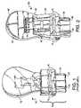
- FIG. 2is a pictorial depiction of a first embodiment of the lamp of the present invention.
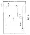
- FIG. 3is a circuit diagram of a ballast circuit for the lamp of the present invention.
- FIG. 4is an exploded view illustrating a method of manufacturing the lamp of the present invention.
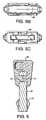
- FIGS. 5 a - care front, top and bottom views, respectively, of an embodiment of the lamp of the present invention.
- FIG. 6is a partial sectional view through line VI-VI of FIG. 5 a.
- FIG. 7is a sectional view through line VII-VII of FIG. 5 a.
- one embodiment of the present inventionis a lamp 30 with a wedge base that includes a generally planar circuit board 32 having one end 34 that has electrical connections 36 exposed thereon and a connecting part 38 that is adapted to mechanically couple the lamp to a wedge-based lamp socket, such as by including the fittings 16 .
- the lamp 30includes an LED light engine 40 near a second end 42 of the circuit board, where the light engine includes one or more LEDs 44 whose light output mimics the light output of an incandescent lamp, such as used in automobile stop and turn signals.
- the lamp 30includes a load resistor 46 , whose load mimics that of the incandescent lamp, on an exterior surface of the connecting part 38 .
- the connecting part 38may be a sleeve that slides onto the circuit board 32 .
- a hand grip/heat sink 48may be provided at the second end 42 of the circuit board 32 .
- the one end 34 of circuit board 32is arranged and adapted to fit into a wedge-based lamp socket (not shown) and the electrical connections 36 thereon are located in correspondence with electrical connections in the socket.
- the electrical connections 36may be tin, brass, copper or similar metal contacts that extend from the bottom edge of the circuit board 32 to connections for the light engine 40 .
- the shape of the top of the circuit board 32may vary as needed to accommodate the light engine 40 .
- FIG. 2shows that the circuit board 32 has a wider portion at the second end 42 to provide room for the LEDs 44 , and other shapes are possible.
- the circuit board 32is preferably heat conductive, and may be a metal substrate such as provided by The Berquist Company under the mark Thermal Clad Insulated Metal Substrate. These substrates minimize thermal impedance and conduct heat more effectively than standard printed wiring boards. They include a base layer of aluminum or other suitable metal, a dielectric layer on the base layer and a printed circuit layer on the dielectric layer.
- the light engine 40includes a sufficient number of LEDs 44 to substantially duplicate the incandescent lamp being replaced or as necessary for a particular application.
- the LEDs 44may be conventional and are preferably aligned in a row near a middle of the top of the circuit board 32 to mimic the filament of an incandescent lamp, although other arrangements are possible.
- the LEDs 44may be mounted on one or both sides of the circuit board 32 and may be carried on a further board 52 for ease of manufacture. Placing the LEDs 44 on both sides allows the lamp to be used in either direction.
- the connecting part 38is preferably a thermal insulator, such as a ceramic, that is mechanically coupled to the circuit board 32 using conventional attachments such as adhesive, screws or pins.
- a thermal insulatorsuch as a ceramic
- the connecting part 38is attached to the circuit board 32 , the combination of the connecting part 38 and end 34 of the circuit board 32 forms the wedge base for the lamp. While the figures show that the connecting part 38 is adapted to mechanically couple the lamp to a wedge-based lamp socket by including the fittings 16 , other fittings that fit a particular type of socket are possible.
- the connecting part 38may be hollow and slide onto the circuit board 32 , or may be two parts that fit on opposite sides of the circuit board 32 .
- the load resistor 46is preferably on one or both sides of an exterior of the connecting part 38 , although other arrangements are possible in which the load resistor is separated from the circuit board 32 by a thermal insulator to isolate the heat of the load resistor 46 from the circuit board 32 .
- the load resistor 46may include two planar resistors that are connected in parallel to circuitry that connects the light engine 40 to the electrical connections 36 .
- the load resistor 46provides a load that simulates a load of a corresponding incandescent lamp and may be sized appropriately.
- a protective coating(not shown), such as silicon or epoxy material, may be applied to the load resistors 46 and circuitry on the circuit board 32 .
- the hand grip/heat sink 48is optional and may be provided either as a grip for grasping the lamp or as a heat sink for the circuit board 32 , or both.
- the embodiment shown in the figuresincludes tapered sides to facilitate grasping the lamp and is made of a suitable heat conducting metal such as zinc, copper or aluminum.
- the hand grip/heat sink 48may also include fins (not shown) or other conventional heat sink features.
- the lamp 30may also include a ballast circuit 54 connecting the light engine 40 to the electrical connections 36 and load resistor 46 .
- the ballast circuitmay be integral with the light engine 40 , such as on the further board 52 .
- the ballast circuit 54may include a phototransistor 56 that is optically coupled to the light engine 40 , a capacitor 58 , a ballast resistor 60 , a first resistor 62 , a field effect transistor (FET) 64 , and a diode 66 .
- the capacitance of capacitor 58 , a resistance of first resistor 62 and a gate turn-on threshold voltage of the FET 56can be set to define ON-OFF cycle times of the lamp.
- the phototransistor 56In operation, when power is applied to the lamp and the LEDs emit light, the phototransistor 56 (recall that it is optically coupled to the LEDs) goes into a low impedance conduction state. This completes the circuit between the + and return through the capacitor 58 , phototransistor 56 and first resistor 62 . Since the capacitor 58 was fully discharged prior to application of voltage at the + terminal, the voltage at the gate of the FET 64 immediately rises to the voltage at the + terminal, turning ON the FET 64 and consequently completing the circuit for the ballast resistor 60 , whose resistance may be set at an appropriate amount, such as 10 ohm. At the same time, the capacitor 58 is charging because the circuit through the phototransistor 56 is complete.
- the capacitor 58As the capacitor 58 charges, the voltage at the gate of the FET 64 decreases. After a time determined by the capacitance of the capacitor 58 , resistance of the first resistor 62 and gate turn-on threshold voltage of the FET 64 , the FET 64 will cease to conduct resulting in the removal of the conduction path for the ballast resistor 60 .
- the period during which the ballast resistor 60 is connectedcan be set to a desired time, such as for an ON-OFF cycle of a conventional automobile turn signal.
- the capacitor 58is discharged through the path provided by the diode 66 and the impedance of the external circuit (not shown) connected to the + terminal. If this impedance is not low enough to fully discharge the capacitor during the OFF time of a normal flashing cycle, a further resistor can be added to the circuit.
- An advantage of this arrangement of circuit 54is that if the LEDs do not light when voltage is applied to the + terminal, the ballast resistor 60 will not be connected and there will not be sufficient current drawn by the lamp to activate the conventional “good lamp” detection circuits in an automobile.
- a further advantageis that if the voltage at the + terminal remains longer than the time set by the circuit to disconnect the ballast resistor 60 , the ballast resistor 60 will disconnect and remain disconnected until the voltage is removed from the + terminal and the circuit 54 is returned to its initial condition.
- the components of circuit 54are sufficiently small to fit on the further board 52 of the light engine 40 .
- the connecting part 38may slide onto circuit board 32 by placing the circuit board 32 into the hollow 70 in connecting part 38 .
- the connecting part 38slides into a position defined by a notch 72 on an edge of the circuit board 32 .
- connecting part 38may be in two pieces (the dashed line on the side of element 38 in FIG. 4 defines a possible division of the connecting part) and fit on opposite sides of the circuit board 32 .
- the further board 52if used, may be attached to the circuit board 32 with a thermally conductive adhesive.
- Suitable circuitry for connecting the electrical connections 36 to the load resistor 46 and light engine 40may be conventionally applied on the surface of the circuit board 32 .
- the load resistor 46may be applied to the exterior of the connecting part 38 by painting or other suitable methods of application of a planar resistor.
- the load resistor 46may include two separate painted areas that are connected in parallel by suitable printed or other circuitry.
- the hand grip/heat sink 48may be applied in two parts (as shown also shown in FIG. 6 ) and have projections 74 that correspond to holes 76 in the circuit board. The two parts may be press fit together. Thereafter, as shown FIG.
- the LEDs 44 , load resistor 46 and electrical connections 36are electrically connected to each other with suitable connectors such as flying leads, spring contacts, solder, clips, jump wires, and the like.
- Jump wires 78are shown in FIG. 7 , by way of example.
- Further circuitry 80may be provided on the circuit board 32 instead of or in addition to the jump wires.
Landscapes
- Engineering & Computer Science (AREA)
- General Engineering & Computer Science (AREA)
- Physics & Mathematics (AREA)
- Microelectronics & Electronic Packaging (AREA)
- Optics & Photonics (AREA)
- Non-Portable Lighting Devices Or Systems Thereof (AREA)
- Fastening Of Light Sources Or Lamp Holders (AREA)
Abstract
Description
Claims (21)
Priority Applications (1)
| Application Number | Priority Date | Filing Date | Title |
|---|---|---|---|
| US10/864,988US7261437B2 (en) | 2004-06-10 | 2004-06-10 | Wedge-based lamp with LED light engine and method of making the lamp |
Applications Claiming Priority (1)
| Application Number | Priority Date | Filing Date | Title |
|---|---|---|---|
| US10/864,988US7261437B2 (en) | 2004-06-10 | 2004-06-10 | Wedge-based lamp with LED light engine and method of making the lamp |
Publications (2)
| Publication Number | Publication Date |
|---|---|
| US20050276063A1 US20050276063A1 (en) | 2005-12-15 |
| US7261437B2true US7261437B2 (en) | 2007-08-28 |
Family
ID=35460327
Family Applications (1)
| Application Number | Title | Priority Date | Filing Date |
|---|---|---|---|
| US10/864,988Expired - Fee RelatedUS7261437B2 (en) | 2004-06-10 | 2004-06-10 | Wedge-based lamp with LED light engine and method of making the lamp |
Country Status (1)
| Country | Link |
|---|---|
| US (1) | US7261437B2 (en) |
Cited By (15)
| Publication number | Priority date | Publication date | Assignee | Title |
|---|---|---|---|---|
| US20070171667A1 (en)* | 2006-01-26 | 2007-07-26 | Koito Manufacturing Co., Ltd. | Vehicular lamp |
| US20080080187A1 (en)* | 2006-09-28 | 2008-04-03 | Purinton Richard S | Sealed LED light bulb |
| US20100182788A1 (en)* | 2009-01-19 | 2010-07-22 | Osram Sylvania Inc. | Led lamp assembly |
| US20100181885A1 (en)* | 2009-01-19 | 2010-07-22 | Osram Sylvania Inc. | LED LAMP ASSEMBLYl |
| US20100213809A1 (en)* | 2007-09-19 | 2010-08-26 | Osram Gesellschaft Mit Beschraenkter Haftung | Headlamp and its use |
| US20120069570A1 (en)* | 2009-05-28 | 2012-03-22 | Koninklijke Philips Electronics N.V. | Illumination device and method for assembly of an illumination device |
| US20120307510A1 (en)* | 2011-06-03 | 2012-12-06 | Koito Manufacturing Co., Ltd. | Vehicle lamp |
| US8376593B2 (en) | 2010-04-30 | 2013-02-19 | Osram Sylvania Inc. | Thermal trim for a luminaire |
| US8833990B2 (en) | 2012-07-18 | 2014-09-16 | Osram Sylvania Inc. | Automotive lamp and socket apparatus with pigtail connector |
| US8894238B2 (en) | 2009-05-28 | 2014-11-25 | Koninklijke Philips N.V. | Ceramic illumination device |
| US8956030B1 (en)* | 1999-05-24 | 2015-02-17 | Jam Strait, Inc. | Automotive bulbs having LEDs pointing in different directions |
| CN105009262A (en)* | 2013-03-15 | 2015-10-28 | 应用材料公司 | Heating lamp assembly |
| US20160003417A1 (en)* | 2012-12-05 | 2016-01-07 | Koninklijke Philips N.V. | Flat lighting device |
| US20160076724A1 (en)* | 2014-09-15 | 2016-03-17 | Valeo Vision | Light source support with integral connector |
| US9638392B2 (en) | 2015-09-25 | 2017-05-02 | Osram Sylvania Inc. | Lamp optic for use in LED-based lamp |
Families Citing this family (12)
| Publication number | Priority date | Publication date | Assignee | Title |
|---|---|---|---|---|
| US7238061B1 (en)* | 2006-09-18 | 2007-07-03 | Yu-Chu Lin | Vehicle lighting source adapter |
| JP5465898B2 (en)* | 2009-03-11 | 2014-04-09 | 日本航空電子工業株式会社 | Optical semiconductor device, socket and optical semiconductor unit |
| US8517583B2 (en)* | 2009-07-24 | 2013-08-27 | Jam Strait, Inc. | Loaded LED bulbs for incandescent/fluorescent/neon/xenon/halogen bulbs replacement in load sensitive applications and more |
| US9277595B2 (en) | 2012-02-24 | 2016-03-01 | Applied Materials, Inc. | Heating lamp having base to facilitate reduced air flow about the heating lamp |
| US9214774B2 (en)* | 2013-03-15 | 2015-12-15 | Epistar Corporation | Wedge converter |
| WO2015032896A1 (en)* | 2013-09-05 | 2015-03-12 | Koninklijke Philips N.V. | Automotive light bulb and luminaire |
| US10260684B2 (en) | 2013-12-17 | 2019-04-16 | Lumileds Llc | Low and high beam LED lamp |
| FR3015853B1 (en)* | 2013-12-20 | 2017-01-27 | Valeo Vision | LED SUPPORT WITH ELECTRICAL CONNECTION BY BRIDGE |
| FR3018398B1 (en)* | 2014-03-07 | 2017-12-22 | Cml Innovative Tech | ADAPTER FOR LED CONNECTION |
| CN105090858A (en)* | 2015-09-10 | 2015-11-25 | 安徽华夏显示技术股份有限公司 | Novel navigation light source for helicopter |
| CN105841066B (en)* | 2016-05-24 | 2019-03-01 | 广州共铸科技股份有限公司 | A kind of automobile LED indicator light |
| KR102204216B1 (en) | 2018-09-07 | 2021-01-20 | 루미리즈 홀딩 비.브이. | Supports and lighting devices for light-emitting elements |
Citations (13)
| Publication number | Priority date | Publication date | Assignee | Title |
|---|---|---|---|---|
| US5160200A (en)* | 1991-03-06 | 1992-11-03 | R & D Molded Products, Inc. | Wedge-base LED bulb housing |
| US6357902B1 (en)* | 2000-09-25 | 2002-03-19 | Brian Horowitz | After market LED taillight bulb |
| US6371636B1 (en)* | 1999-05-24 | 2002-04-16 | Jam Strait, Inc. | LED light module for vehicles |
| US6580228B1 (en)* | 2000-08-22 | 2003-06-17 | Light Sciences Corporation | Flexible substrate mounted solid-state light sources for use in line current lamp sockets |
| US6598996B1 (en)* | 2001-04-27 | 2003-07-29 | Pervaiz Lodhie | LED light bulb |
| US6727652B2 (en)* | 2000-12-21 | 2004-04-27 | Gamesman Limited | Lamps |
| US6737811B2 (en)* | 2001-06-16 | 2004-05-18 | A L Lightech, Inc. | High intensity light source arrangement |
| US20040156213A1 (en)* | 2002-07-19 | 2004-08-12 | Pervaiz Lodhie | LED lamp for vehicle signal light |
| US6803607B1 (en)* | 2003-06-13 | 2004-10-12 | Cotco Holdings Limited | Surface mountable light emitting device |
| US20040201990A1 (en)* | 2003-04-10 | 2004-10-14 | Meyer William E. | LED lamp |
| US6827469B2 (en)* | 2003-02-03 | 2004-12-07 | Osram Sylvania Inc. | Solid-state automotive lamp |
| US20050030761A1 (en)* | 2003-02-03 | 2005-02-10 | Burgess Edward Sean | Package LED's and electronics as a replaceable light bulb |
| US6880962B2 (en)* | 2002-12-09 | 2005-04-19 | Osram Sylvania, Inc. | LED light source mimicking a filamented lamp |
- 2004
- 2004-06-10USUS10/864,988patent/US7261437B2/ennot_activeExpired - Fee Related
Patent Citations (13)
| Publication number | Priority date | Publication date | Assignee | Title |
|---|---|---|---|---|
| US5160200A (en)* | 1991-03-06 | 1992-11-03 | R & D Molded Products, Inc. | Wedge-base LED bulb housing |
| US6371636B1 (en)* | 1999-05-24 | 2002-04-16 | Jam Strait, Inc. | LED light module for vehicles |
| US6580228B1 (en)* | 2000-08-22 | 2003-06-17 | Light Sciences Corporation | Flexible substrate mounted solid-state light sources for use in line current lamp sockets |
| US6357902B1 (en)* | 2000-09-25 | 2002-03-19 | Brian Horowitz | After market LED taillight bulb |
| US6727652B2 (en)* | 2000-12-21 | 2004-04-27 | Gamesman Limited | Lamps |
| US6598996B1 (en)* | 2001-04-27 | 2003-07-29 | Pervaiz Lodhie | LED light bulb |
| US6737811B2 (en)* | 2001-06-16 | 2004-05-18 | A L Lightech, Inc. | High intensity light source arrangement |
| US20040156213A1 (en)* | 2002-07-19 | 2004-08-12 | Pervaiz Lodhie | LED lamp for vehicle signal light |
| US6880962B2 (en)* | 2002-12-09 | 2005-04-19 | Osram Sylvania, Inc. | LED light source mimicking a filamented lamp |
| US6827469B2 (en)* | 2003-02-03 | 2004-12-07 | Osram Sylvania Inc. | Solid-state automotive lamp |
| US20050030761A1 (en)* | 2003-02-03 | 2005-02-10 | Burgess Edward Sean | Package LED's and electronics as a replaceable light bulb |
| US20040201990A1 (en)* | 2003-04-10 | 2004-10-14 | Meyer William E. | LED lamp |
| US6803607B1 (en)* | 2003-06-13 | 2004-10-12 | Cotco Holdings Limited | Surface mountable light emitting device |
Cited By (24)
| Publication number | Priority date | Publication date | Assignee | Title |
|---|---|---|---|---|
| US8956030B1 (en)* | 1999-05-24 | 2015-02-17 | Jam Strait, Inc. | Automotive bulbs having LEDs pointing in different directions |
| US20070171667A1 (en)* | 2006-01-26 | 2007-07-26 | Koito Manufacturing Co., Ltd. | Vehicular lamp |
| US20080080187A1 (en)* | 2006-09-28 | 2008-04-03 | Purinton Richard S | Sealed LED light bulb |
| US20100213809A1 (en)* | 2007-09-19 | 2010-08-26 | Osram Gesellschaft Mit Beschraenkter Haftung | Headlamp and its use |
| US20100182788A1 (en)* | 2009-01-19 | 2010-07-22 | Osram Sylvania Inc. | Led lamp assembly |
| US20100181885A1 (en)* | 2009-01-19 | 2010-07-22 | Osram Sylvania Inc. | LED LAMP ASSEMBLYl |
| US7923907B2 (en) | 2009-01-19 | 2011-04-12 | Osram Sylvania Inc. | LED lamp assembly |
| US7946732B2 (en) | 2009-01-19 | 2011-05-24 | Osram Sylvania Inc. | LED lamp assembly |
| US8894238B2 (en) | 2009-05-28 | 2014-11-25 | Koninklijke Philips N.V. | Ceramic illumination device |
| US9360203B2 (en)* | 2009-05-28 | 2016-06-07 | Koninklijke Philips N.V. | Illumination device and method for assembly of an illumination device |
| US20120069570A1 (en)* | 2009-05-28 | 2012-03-22 | Koninklijke Philips Electronics N.V. | Illumination device and method for assembly of an illumination device |
| US9746171B2 (en) | 2009-05-28 | 2017-08-29 | Philips Lighting Holding B.V. | Illumination device |
| US8585259B2 (en) | 2010-04-30 | 2013-11-19 | Osram Sylvania Inc. | Thermal trim for luminaire |
| KR101819024B1 (en) | 2010-04-30 | 2018-01-16 | 오스람 실바니아 인코포레이티드 | Thermal trim for a luminaire |
| US8376593B2 (en) | 2010-04-30 | 2013-02-19 | Osram Sylvania Inc. | Thermal trim for a luminaire |
| US20120307510A1 (en)* | 2011-06-03 | 2012-12-06 | Koito Manufacturing Co., Ltd. | Vehicle lamp |
| US8985823B2 (en)* | 2011-06-03 | 2015-03-24 | Koito Manufacturing Co., Ltd. | Vehicle lamp having an LED and a drip-preventive cover |
| US8833990B2 (en) | 2012-07-18 | 2014-09-16 | Osram Sylvania Inc. | Automotive lamp and socket apparatus with pigtail connector |
| US20160003417A1 (en)* | 2012-12-05 | 2016-01-07 | Koninklijke Philips N.V. | Flat lighting device |
| US10006608B2 (en)* | 2012-12-05 | 2018-06-26 | Philips Lighting Holding B.V. | Flat lighting device |
| CN105009262A (en)* | 2013-03-15 | 2015-10-28 | 应用材料公司 | Heating lamp assembly |
| CN105009262B (en)* | 2013-03-15 | 2017-12-08 | 应用材料公司 | Heating lamp component |
| US20160076724A1 (en)* | 2014-09-15 | 2016-03-17 | Valeo Vision | Light source support with integral connector |
| US9638392B2 (en) | 2015-09-25 | 2017-05-02 | Osram Sylvania Inc. | Lamp optic for use in LED-based lamp |
Also Published As
| Publication number | Publication date |
|---|---|
| US20050276063A1 (en) | 2005-12-15 |
Similar Documents
| Publication | Publication Date | Title |
|---|---|---|
| US7261437B2 (en) | Wedge-based lamp with LED light engine and method of making the lamp | |
| US7676915B2 (en) | Process for manufacturing an LED lamp with integrated heat sink | |
| US10641474B2 (en) | Light string and manufacturing method thereof | |
| US8324642B2 (en) | Light emitting diode assembly and methods | |
| US7322718B2 (en) | Multichip LED lighting device | |
| US20100240158A1 (en) | Led lighting with integrated heat sink and process for manufacturing same | |
| US20070257274A1 (en) | Lighting Device And Method | |
| US20090103295A1 (en) | LED unit and LED module | |
| JP2002539626A (en) | Photoelectric element | |
| US20100163890A1 (en) | Led lighting device | |
| US20090273300A1 (en) | Variable Intensity LED Illumination System | |
| US20100109553A1 (en) | Led bulb with zener diode, zener diode assembly or resistor connected in series | |
| JP2006196684A (en) | LED module, lighting apparatus, and method of manufacturing LED module | |
| US8926153B2 (en) | Integrated light pipe and LED | |
| US20120025719A1 (en) | LED Tube and Drive Circuit thereof | |
| US11739917B2 (en) | Miniature LED lightbulb mounting device | |
| US12018806B2 (en) | Halogen lamp replacement | |
| CN204704694U (en) | LED illumination lamp | |
| CN212305722U (en) | LED driving module and lighting lamp | |
| US20110006704A1 (en) | Lead frame by wire binding method and led power lamp using same | |
| US20220295617A1 (en) | Led device with lateral light emission | |
| JP7063171B2 (en) | Vehicle lighting equipment | |
| US11384930B1 (en) | Heat sink for lighting devices | |
| CN220692023U (en) | LED lamp with built-in IC lamp beads | |
| JP2004063237A (en) | Lighting equipment using light emitting diodes |
Legal Events
| Date | Code | Title | Description |
|---|---|---|---|
| AS | Assignment | Owner name:OSRAM SYLVANIA INC., MASSACHUSETTS Free format text:ASSIGNMENT OF ASSIGNORS INTEREST;ASSIGNORS:COUSHAINE, CHARLES M.;SIDWELL, STEVE C.;TESSNOW, THOMAS;AND OTHERS;REEL/FRAME:015459/0788;SIGNING DATES FROM 20040602 TO 20040607 | |
| STCF | Information on status: patent grant | Free format text:PATENTED CASE | |
| AS | Assignment | Owner name:OSRAM SYLVANIA INC., MASSACHUSETTS Free format text:MERGER;ASSIGNOR:OSRAM SYLVANIA INC.;REEL/FRAME:025549/0548 Effective date:20100902 | |
| FPAY | Fee payment | Year of fee payment:4 | |
| FEPP | Fee payment procedure | Free format text:PAYOR NUMBER ASSIGNED (ORIGINAL EVENT CODE: ASPN); ENTITY STATUS OF PATENT OWNER: LARGE ENTITY | |
| FPAY | Fee payment | Year of fee payment:8 | |
| FEPP | Fee payment procedure | Free format text:MAINTENANCE FEE REMINDER MAILED (ORIGINAL EVENT CODE: REM.); ENTITY STATUS OF PATENT OWNER: LARGE ENTITY | |
| LAPS | Lapse for failure to pay maintenance fees | Free format text:PATENT EXPIRED FOR FAILURE TO PAY MAINTENANCE FEES (ORIGINAL EVENT CODE: EXP.); ENTITY STATUS OF PATENT OWNER: LARGE ENTITY | |
| STCH | Information on status: patent discontinuation | Free format text:PATENT EXPIRED DUE TO NONPAYMENT OF MAINTENANCE FEES UNDER 37 CFR 1.362 | |
| FP | Lapsed due to failure to pay maintenance fee | Effective date:20190828 |