US7261261B2 - Stand of free standing or mobile type - Google Patents
Stand of free standing or mobile typeDownload PDFInfo
- Publication number
- US7261261B2 US7261261B2US10/521,956US52195605AUS7261261B2US 7261261 B2US7261261 B2US 7261261B2US 52195605 AUS52195605 AUS 52195605AUS 7261261 B2US7261261 B2US 7261261B2
- Authority
- US
- United States
- Prior art keywords
- column
- stand
- front panel
- floor mount
- spine
- Prior art date
- Legal status (The legal status is an assumption and is not a legal conclusion. Google has not performed a legal analysis and makes no representation as to the accuracy of the status listed.)
- Expired - Fee Related
Links
- 230000008878couplingEffects0.000claimsdescription9
- 238000010168coupling processMethods0.000claimsdescription9
- 238000005859coupling reactionMethods0.000claimsdescription9
- 235000004443Ricinus communisNutrition0.000description2
- 240000000528Ricinus communisSpecies0.000description2
- 230000005484gravityEffects0.000description2
- 238000000926separation methodMethods0.000description2
- 230000002411adverseEffects0.000description1
- 230000000717retained effectEffects0.000description1
- 238000005096rolling processMethods0.000description1
- 230000000007visual effectEffects0.000description1
Images


Classifications
- A—HUMAN NECESSITIES
- A47—FURNITURE; DOMESTIC ARTICLES OR APPLIANCES; COFFEE MILLS; SPICE MILLS; SUCTION CLEANERS IN GENERAL
- A47B—TABLES; DESKS; OFFICE FURNITURE; CABINETS; DRAWERS; GENERAL DETAILS OF FURNITURE
- A47B21/00—Tables or desks for office equipment, e.g. typewriters, keyboards
- F—MECHANICAL ENGINEERING; LIGHTING; HEATING; WEAPONS; BLASTING
- F16—ENGINEERING ELEMENTS AND UNITS; GENERAL MEASURES FOR PRODUCING AND MAINTAINING EFFECTIVE FUNCTIONING OF MACHINES OR INSTALLATIONS; THERMAL INSULATION IN GENERAL
- F16M—FRAMES, CASINGS OR BEDS OF ENGINES, MACHINES OR APPARATUS, NOT SPECIFIC TO ENGINES, MACHINES OR APPARATUS PROVIDED FOR ELSEWHERE; STANDS; SUPPORTS
- F16M11/00—Stands or trestles as supports for apparatus or articles placed thereon ; Stands for scientific apparatus such as gravitational force meters
- F16M11/20—Undercarriages with or without wheels
- F16M11/22—Undercarriages with or without wheels with approximately constant height, e.g. with constant length of column or of legs
- F—MECHANICAL ENGINEERING; LIGHTING; HEATING; WEAPONS; BLASTING
- F16—ENGINEERING ELEMENTS AND UNITS; GENERAL MEASURES FOR PRODUCING AND MAINTAINING EFFECTIVE FUNCTIONING OF MACHINES OR INSTALLATIONS; THERMAL INSULATION IN GENERAL
- F16M—FRAMES, CASINGS OR BEDS OF ENGINES, MACHINES OR APPARATUS, NOT SPECIFIC TO ENGINES, MACHINES OR APPARATUS PROVIDED FOR ELSEWHERE; STANDS; SUPPORTS
- F16M11/00—Stands or trestles as supports for apparatus or articles placed thereon ; Stands for scientific apparatus such as gravitational force meters
- F16M11/42—Stands or trestles as supports for apparatus or articles placed thereon ; Stands for scientific apparatus such as gravitational force meters with arrangement for propelling the support stands on wheels
- Y—GENERAL TAGGING OF NEW TECHNOLOGICAL DEVELOPMENTS; GENERAL TAGGING OF CROSS-SECTIONAL TECHNOLOGIES SPANNING OVER SEVERAL SECTIONS OF THE IPC; TECHNICAL SUBJECTS COVERED BY FORMER USPC CROSS-REFERENCE ART COLLECTIONS [XRACs] AND DIGESTS
- Y10—TECHNICAL SUBJECTS COVERED BY FORMER USPC
- Y10S—TECHNICAL SUBJECTS COVERED BY FORMER USPC CROSS-REFERENCE ART COLLECTIONS [XRACs] AND DIGESTS
- Y10S248/00—Supports
- Y10S248/917—Video display screen support
Definitions
- This inventionrelates to a stand. It is particularly concerned with a stand of a free standing or mobile type for supporting a relatively bulky object above floor or ground level while providing for stable directional alignment of the object relative to a datum direction from the stand.
- a display unitsuch as a plasma screen
- a display unitcan be raised well above the general eye level and mounted on an existing structure.
- a free standing standwhich is readily located at will in order to support a display unit in a stable manner and at a height providing for unimpeded viewing by, say, visitors to exhibitions, seated individuals at a meeting, students under instruction or employees undergoing staff training.
- Such display locationsparticularly when temporary, require the use of a display stand, which is either complete or readily assembled.
- the standneeds to be capable of ready location and removal or movement.
- a display unitneeds to be provided with one or more external link/s to a power and/or a data source.
- the presence of such a link or linksshould not present a hazard to individuals moving in the vicinity of the stand especially when ambient light levels are low.
- the attachment and securing of such linksshould not adversely affect the stability of the stand. It is also desirable in many locations, particularly prestigious ones, that the overall appearance of the stand in use (along with any attachments and their means of attachment) should not present an untidy or ramshackle appearance.
- a standcomprising:
- At least one columnextending between the floor mount to which it is attached by a first attachment and the location means which is attached to, or integral with, an upper region of the or each column; the column having a longitudinal axis which is curved relative to a straight line extending between the first attachment and the location means;
- the, or each, columnserving to transmit loads applied to the stand by way of the location means to the floor mount;
- the, or each, columncomprising a hollow channel substantially symmetrical about the longitudinal axis of the front panel; the hollow spine having a cross section in the region of the floor stand which is greater than the cross section of the spine in the region of the location means.
- the, or at least one, columncomprises in combination:
- a front panelextending between floor mount and the location means and reducing in horizontal cross section in passing upwardly from the floor mount to the location means; the front panel having a longitudinal axis which is curved relative to a straight line extending between the first attachment and the second attachment;
- a hollow spine of U-section channelattached to the front panel such that the front panel serves to close the U-section such that the front panel and the hollow spine in combination provide a column substantially symmetrical about the longitudinal axis of the front panel; the hollow spine having a cross section in the region of the floor stand which is greater than the cross section of the spine in the region of the location means.
- the, or at least one, columnhas a sequence of apertures along at least part of the length of a wall of the column channel to enable a cable to be readily inserted into and drawn along the channel so as to extend within the spine from an entry into the spine by way of an aperture in the sequence in the vicinity of the floor stand and to pass out of the column by way of an aperture in the sequence in the vicinity of the location means so as to provide for the cable to provide a shrouded path for data or power cable within the, or each, column having a sequence of apertures as aforesaid.
- a coupling meansincluding a socket or other supply termination for a power supply and/or a data coupling to enable a unit to be attached by means of attached to the locating means to be demountably attached to a power or data supply.
- the couplingis fed power and/or data by way of at least one cable extending from the coupling along the column by way of the hollow spine.
- the front panelincorporates at least one longitudinal slot extending through the panel; the slot having an edge on the side of the panel which extends contiguously with an outside of a side wall of the U-section channel such that a flat member inserted through the slot from the side of the panel on the opposite side to the side to which the spine is attached is enabled to pass through the slot and lie in contact with the side wall for support thereby over an extend contact area.
- a shelf supportextends through the slot for attachment to the spine; the support projecting outwardly from the front of the front panel to receive a shelf to support an item or item at a location beneath the location means.
- the floor mountis demountably attached to the column by coupling means so that a floor mount having given outside dimension can only be attached to a column whose height is related to the outside dimensions of the floor mount so that the combination of the floor mount and the column can support an added display or other unit secured to the location means in a stable configuration without added support.
- the floor mountis provided with wheels to enable the stand to be displaced by rolling on the wheels.
- a display assemblycomprising a display unit secured to the locating means of a stand as claimed in any preceding claim.
- the display unitis a plasma screen.
- FIG. 1is a front view from the left-hand side
- FIG. 2is a front elevation
- FIG. 3is a side elevation
- FIG. 4is a rear elevation
- FIG. 5is a view of the stand shown in FIGS. 1 to 4 with equipment mounted on it;
- FIG. 6is a front view from the left-hand side
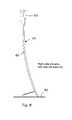
- FIG. 7is a front elevation
- FIG. 8is a side elevation
- FIG. 9is a rear elevation
- FIG. 10is a plan view from above
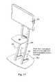
- FIG. 11is a view from the front of the stand shown in FIGS. 6 to 10 with equipment mounted on it;
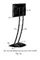
- FIG. 12is a rear view of the stand of FIGS. 6 to 10 with a display screen mounted on it.
- FIGS. 1 to 5variously show a stand 11 comprising a floor mount 12 , a location pad 13 for a unit to be supported; and a column 14 extending between the floor mount 12 to the location pad 13 which, in this case, is integral with the column 14 .
- the column 14serves to transmit loads applied to the stand 11 by way of the location pad 13 .
- the column 14comprises in combination: a front panel 16 extending between floor mount 12 and the location pad 13 .
- the front panel 16reduces in horizontal cross section in passing upwardly from the floor mount 12 to the location pad 13 .
- the front panel 16has a longitudinal axis 16 A that is curved relative to a straight line 16 B extending between foot 17 of the column 14 and the location pad 13 .
- a hollow spine 20 of U-section channelis attached to the back of the front panel 16 such that the front panel 16 serves to close the U-section.
- the front panel 16 and the hollow spine 20 in combinationprovide column 14 .
- the hollow spine 20has a horizontal cross section in the region of the floor mount 12 that is greater than the cross section of the spine 20 in the region of the location pad 13 .
- the hollow spine 20has in its rear wall 21 a sequence of apertures 22 A-G along the length of spine to enable one or more power cables to be readily inserted into and drawn internally along the spine 20 so as to extend within the spine from entry aperture 22 A adjacent the floor mount 12 up the spine 20 to a terminal block 25 above the location pad 13 .
- the terminal blockprovides individual sockets 25 A- 25 D.
- a similar pathcan be used to provide a route for data or other signal carrying cables which can enter at the entry aperture 22 A or can enter at some intermediate point in the length of the spine 20 (such as from equipment mounted on a shelf described hereafter in connection with FIG. 5 ).
- the front plate 16 of the column 14is pierced by two vertical parallel slots 30 , 31 . These pass through plate 16 and open onto back 16 B of the plate 16 close to a sidewall of the spine 20 .
- slot 31FIG. 3
- An adjacent vertical pair of pegs in the sequenceserve to anchor a shelf 35 the in-board end of a support bracket 36 A whose outboard end extends through the slot 31 to provide a support on the front of the column 14 for shelf 35 .
- a matching shelf support 36 Bextends through slot 30 and is retained on the spine 20 in a way mirroring that of support bracket 36 .
- the vertical separation of the pegs 34 A-Gis selected to ensure that despite the curvature of the column along wall region W the vertical separation of shelf 35 from any other shelf also located on the column is kept constant and the shelf is maintained horizontal. In this first embodiment it is provided so that up to three shelves can be located and used at any one time.
- FIG. 5shows a plasma screen 40 secured to the location pad 13 by way of a mounting frame 41 .
- the shelf 35serves to support electronic equipment for use with the plasma screen 40 such as a video playback unit.
- a video playback unitis readily powered from the terminal block 25 and the cable for this [purpose, as well as a data link cable from the recorder to the plasma screen, is readily and tidily housed in the spine 20 making use of one of intermediate apertures in the sequence aperture 22 B to 22 G.
- the column 14is attached by projections (not shown) and bolts 41 , 42 to the wheeled base 12 .
- the location of castors 43 - 46is selected to ensure that the center of gravity of the assembled stand and display unit lies well within the area bounded by the castors 43 - 46 .
- FIGS. 6 to 12variously show a stand 61 comprising a floor mount 62 , a location region 63 for a unit to be supported; and columns 64 , 65 extending between the floor mount 62 to the location region 63 .
- the column 64 , 65serves to transmit loads applied to the stand 11 in the location region 63 .
- column 64In view of the identical form and function of columns 64 , 65 in what follows the features of column 64 are described and components identified by a reference numeral. Following the reference numeral for column 64 the corresponding reference numeral for column 65 is shown in brackets but are not described further.
- Column 64 ( 65 )comprises a square section hollow tube.
- Column 64 ( 65 )has a longitudinal axis 64 A ( 65 A) which is curved relative to a straight line 64 B ( 65 B) extending between foot 67 ( 68 ) of the column 64 ( 65 ) and the part of column 64 ( 65 ) lying in the location region 63 .
- the column 64 ( 65 )has in its rear wall 72 ( 73 ) a sequence of apertures 74 A-G ( 75 A-G) along the length of the column 64 ( 65 ) to enable one or more power cables to be readily inserted into and drawn internally along the column 64 ( 65 ) so as to extend within the spine from entry aperture 74 A ( 75 A) adjacent the integral foot 70 ( 71 ) up the column 64 ( 65 ) to a terminal block 77 in the location region 63 .
- end 70 A ( 71 A) of the integral foot 70 ( 71 )is open and can provide a further possible entry point for cabling.
- terminal block 77provides individual power sockets.
- a similar pathcan be used to provide a route for data or other signal carrying cables which can enter at the entry aperture 74 A ( 75 A) or can enter at some intermediate point in the length of the column 64 ( 65 ) (such as from equipment mounted on a shelf described hereafter in connection with FIG. 11 ).
- FIG. 11shows the stand of FIGS. 6-10 when equipped with a plasma screen 79 (see also FIG. 12 ) and a shelf 80 secured by clamp 81 to a mounting bracket 82 .
- the bracketis attached to the columns 64 ( 65 ) by means of apertures in the sequence 74 A-G ( 75 A-G).
- the shelf 80is used for an electronic unit (such as a video recorder) used in combination with screen 79 .
- FIG. 12shows a mounting plate 78 secured to the columns 64 ( 65 ) in the location region 63 .
- the mounting plate 78is selected so as to accommodate the plasma screen 79 to be used.
- the floor mount 62is a flat plate which is readily slid over smooth and/or uniform surfaces.
- the dimensions of the floor mount 62 and the curvature of columns 64 ( 65 )is selected to ensure that with a given plasma screen 79 in place the center of gravity of the screen/column combination lies well within the plan area of the floor mount so as to provide for a stable configuration in use.
- the two embodimentsshow freestanding columns of striking appearance for use with types of audio/visual equipment. Examples of display units are shown but the stands could be used for other equipment requiring an elevated position such as a loud speaker or array of speakers.
- either of the standsprovides for equipment to be connected to one or more cables. These can reach the stand over surrounding ground, floor or carpet and enter the column at a low point, pass up the column to a socket or other connection arrangement in the vicinity of the region of the unit mounted at the top of the stand. This provides for a tidy appearance,
- the standsalso provide for the ready mounting of additional equipment to be used with a display unit as shown located on the upper part of the stand.
Landscapes
- Engineering & Computer Science (AREA)
- General Engineering & Computer Science (AREA)
- Mechanical Engineering (AREA)
- Devices For Indicating Variable Information By Combining Individual Elements (AREA)
Abstract
Description
This application is a national stage completion of PCT/GB2004/002161 filed May 20, 2004, which in turn claims priority from British Application Serial No. 0311945.0 filed May 23, 2003.
This invention relates to a stand. It is particularly concerned with a stand of a free standing or mobile type for supporting a relatively bulky object above floor or ground level while providing for stable directional alignment of the object relative to a datum direction from the stand.
There is a widespread and increasing need for mounting a display unit, such as a plasma screen, so that a number of people can readily comprehend information displayed by way of the unit. In the case of areas such as concourses, airport passenger areas, sporting arenas and stations a display unit can be raised well above the general eye level and mounted on an existing structure. However for other viewing situations there arises a need for a free standing stand which is readily located at will in order to support a display unit in a stable manner and at a height providing for unimpeded viewing by, say, visitors to exhibitions, seated individuals at a meeting, students under instruction or employees undergoing staff training. Such display locations, particularly when temporary, require the use of a display stand, which is either complete or readily assembled. The stand needs to be capable of ready location and removal or movement. In addition a display unit needs to be provided with one or more external link/s to a power and/or a data source. The presence of such a link or links should not present a hazard to individuals moving in the vicinity of the stand especially when ambient light levels are low. In addition the attachment and securing of such links should not adversely affect the stability of the stand. It is also desirable in many locations, particularly prestigious ones, that the overall appearance of the stand in use (along with any attachments and their means of attachment) should not present an untidy or ramshackle appearance.
According to a first aspect of the present invention there is provided a stand comprising:
a floor mount,
a location means for a unit to be supported; and
at least one column extending between the floor mount to which it is attached by a first attachment and the location means which is attached to, or integral with, an upper region of the or each column; the column having a longitudinal axis which is curved relative to a straight line extending between the first attachment and the location means;
the, or each, column serving to transmit loads applied to the stand by way of the location means to the floor mount; the, or each, column comprising a hollow channel substantially symmetrical about the longitudinal axis of the front panel; the hollow spine having a cross section in the region of the floor stand which is greater than the cross section of the spine in the region of the location means.
According to a first preferred version of the first aspect of the present invention the, or at least one, column comprises in combination:
a front panel extending between floor mount and the location means and reducing in horizontal cross section in passing upwardly from the floor mount to the location means; the front panel having a longitudinal axis which is curved relative to a straight line extending between the first attachment and the second attachment; and
a hollow spine of U-section channel attached to the front panel such that the front panel serves to close the U-section such that the front panel and the hollow spine in combination provide a column substantially symmetrical about the longitudinal axis of the front panel; the hollow spine having a cross section in the region of the floor stand which is greater than the cross section of the spine in the region of the location means.
According to a second preferred version of the first aspect of the present invention the, or at least one, column has a sequence of apertures along at least part of the length of a wall of the column channel to enable a cable to be readily inserted into and drawn along the channel so as to extend within the spine from an entry into the spine by way of an aperture in the sequence in the vicinity of the floor stand and to pass out of the column by way of an aperture in the sequence in the vicinity of the location means so as to provide for the cable to provide a shrouded path for data or power cable within the, or each, column having a sequence of apertures as aforesaid.
According to a third preferred version of the first aspect of the present invention or of any preceding preferred version thereof there is provided on the column in the vicinity of the location a coupling means including a socket or other supply termination for a power supply and/or a data coupling to enable a unit to be attached by means of attached to the locating means to be demountably attached to a power or data supply. Typically the coupling is fed power and/or data by way of at least one cable extending from the coupling along the column by way of the hollow spine.
According to a fourth preferred version of the first aspect of the present invention or of any preceding preferred version thereof the front panel incorporates at least one longitudinal slot extending through the panel; the slot having an edge on the side of the panel which extends contiguously with an outside of a side wall of the U-section channel such that a flat member inserted through the slot from the side of the panel on the opposite side to the side to which the spine is attached is enabled to pass through the slot and lie in contact with the side wall for support thereby over an extend contact area. Typically a shelf support extends through the slot for attachment to the spine; the support projecting outwardly from the front of the front panel to receive a shelf to support an item or item at a location beneath the location means.
According to a fifth preferred version of the first aspect of the present invention or of any preceding preferred version thereof the floor mount is demountably attached to the column by coupling means so that a floor mount having given outside dimension can only be attached to a column whose height is related to the outside dimensions of the floor mount so that the combination of the floor mount and the column can support an added display or other unit secured to the location means in a stable configuration without added support.
According to a sixth preferred version of the first aspect of the present invention or of any preceding preferred version wherein the floor mount is provided with wheels to enable the stand to be displaced by rolling on the wheels.
According to a second aspect of the present invention there is provided a display assembly comprising a display unit secured to the locating means of a stand as claimed in any preceding claim. Typically the display unit is a plasma screen.
An exemplary embodiment of the invention will now be described with reference to the accompanying drawings of two embodiments of audio-visual equipment stand in respect of which:
(for a first embodiment)
(for a second embodiment)
Thecolumn 14 comprises in combination: afront panel 16 extending betweenfloor mount 12 and thelocation pad 13. Thefront panel 16 reduces in horizontal cross section in passing upwardly from thefloor mount 12 to thelocation pad 13. Thefront panel 16 has alongitudinal axis 16A that is curved relative to astraight line 16B extending betweenfoot 17 of thecolumn 14 and thelocation pad 13.
Ahollow spine 20 of U-section channel is attached to the back of thefront panel 16 such that thefront panel 16 serves to close the U-section. Thefront panel 16 and thehollow spine 20 in combination providecolumn 14. Thehollow spine 20 has a horizontal cross section in the region of thefloor mount 12 that is greater than the cross section of thespine 20 in the region of thelocation pad 13.
Turning now toFIGS. 4 and 5 thehollow spine 20 has in its rear wall21 a sequence ofapertures 22A-G along the length of spine to enable one or more power cables to be readily inserted into and drawn internally along thespine 20 so as to extend within the spine fromentry aperture 22A adjacent thefloor mount 12 up thespine 20 to aterminal block 25 above thelocation pad 13. In this case the terminal block provides individual sockets25A-25D. A similar path can be used to provide a route for data or other signal carrying cables which can enter at theentry aperture 22A or can enter at some intermediate point in the length of the spine20 (such as from equipment mounted on a shelf described hereafter in connection withFIG. 5 ).
Thefront plate 16 of thecolumn 14 is pierced by two verticalparallel slots plate 16 and open ontoback 16B of theplate 16 close to a sidewall of thespine 20. In the case of slot31 (FIG. 3 ) there is mounted on wall region W, ofspine 20, adjacent to, and running the length of, the slot31 a spaced sequence of pegs (34A-G). An adjacent vertical pair of pegs in the sequence serve to anchor ashelf 35 the in-board end of asupport bracket 36A whose outboard end extends through theslot 31 to provide a support on the front of thecolumn 14 forshelf 35. A matchingshelf support 36B extends throughslot 30 and is retained on thespine 20 in a way mirroring that of support bracket36.
The vertical separation of thepegs 34A-G is selected to ensure that despite the curvature of the column along wall region W the vertical separation ofshelf 35 from any other shelf also located on the column is kept constant and the shelf is maintained horizontal. In this first embodiment it is provided so that up to three shelves can be located and used at any one time.
Theshelf 35 serves to support electronic equipment for use with theplasma screen 40 such as a video playback unit. Such a unit is readily powered from theterminal block 25 and the cable for this [purpose, as well as a data link cable from the recorder to the plasma screen, is readily and tidily housed in thespine 20 making use of one of intermediate apertures in thesequence aperture 22B to22G.
In this first embodiment thecolumn 14 is attached by projections (not shown) andbolts wheeled base 12. The location of castors43-46 is selected to ensure that the center of gravity of the assembled stand and display unit lies well within the area bounded by the castors43-46.
In view of the identical form and function ofcolumns column 64 are described and components identified by a reference numeral. Following the reference numeral forcolumn 64 the corresponding reference numeral forcolumn 65 is shown in brackets but are not described further.
Column64 (65) comprises a square section hollow tube. Column64 (65) has alongitudinal axis 64A (65A) which is curved relative to astraight line 64B (65B) extending between foot67 (68) of the column64 (65) and the part of column64 (65) lying in thelocation region 63. At foot67 (68) of column64 (65) there is provided an integral foot70 (71).
Turning now toFIGS. 9 and 12 the column64 (65) has in its rear wall72 (73) a sequence ofapertures 74A-G (75A-G) along the length of the column64 (65) to enable one or more power cables to be readily inserted into and drawn internally along the column64 (65) so as to extend within the spine fromentry aperture 74A (75A) adjacent the integral foot70 (71) up the column64 (65) to aterminal block 77 in thelocation region 63. In this embodiment end70A (71A) of the integral foot70 (71) is open and can provide a further possible entry point for cabling.
In this case theterminal block 77 provides individual power sockets. A similar path can be used to provide a route for data or other signal carrying cables which can enter at theentry aperture 74A (75A) or can enter at some intermediate point in the length of the column64 (65) (such as from equipment mounted on a shelf described hereafter in connection withFIG. 11 ).
In this second embodiment thefloor mount 62 is a flat plate which is readily slid over smooth and/or uniform surfaces. The dimensions of thefloor mount 62 and the curvature of columns64 (65) is selected to ensure that with a givenplasma screen 79 in place the center of gravity of the screen/column combination lies well within the plan area of the floor mount so as to provide for a stable configuration in use.
The two embodiments show freestanding columns of striking appearance for use with types of audio/visual equipment. Examples of display units are shown but the stands could be used for other equipment requiring an elevated position such as a loud speaker or array of speakers. In use either of the stands provides for equipment to be connected to one or more cables. These can reach the stand over surrounding ground, floor or carpet and enter the column at a low point, pass up the column to a socket or other connection arrangement in the vicinity of the region of the unit mounted at the top of the stand. This provides for a tidy appearance, The stands also provide for the ready mounting of additional equipment to be used with a display unit as shown located on the upper part of the stand.
Claims (8)
1. A stand comprising:
a floor mount; a location means for a unit to be supported; and at least one column extending between the floor mount to which the column is attached by a first attachment and the location means which is attached to, or integral with, an upper region of the at least one column; the column having a longitudinal axis which is curved relative to a straight line extending between the first attachment and the location means; the at least one column comprising in combination;
a front panel extending between floor mount and the location means and reducing in horizontal cross-section in passing upwardly from the floor mount to the location means; the front panel having a longitudinal axis which is curved relative to a straight line extending between the first attachment and the second attachment;
a hollow spine of U-section channel attached to the front panel such that the front panel serves to close the U-section so that the front panel and the hollow spine in combination provide for the column to be substantially symmetrical about the longitudinal axis of the front panel; the hollow spine having a cross-section in the region of the floor stand which is greater than the cross-section of the spine in the region of the location means; the at least one column serving to transmit loads applied to the stand by way of the location means to the floor mount; the at least one column comprising a hollow channel substantially symmetrical about the longitudinal axis of the front panel; and a hollow spine having a cross-section in the region of the floor stand which is greater than the cross-section of the spine in the region of the location means.
2. The stand according toclaim 1 , wherein the at least one column has a sequence of apertures along at least part of the length of a wall of the column channel to enable a cable to be readily inserted into and drawn along the channel so as to extend within the column from an entry into the column by way of an aperture in the sequence in the vicinity of the floor mount and to pass out of the column by way of an aperture in the sequence in the vicinity of the location means so as to provide for the cable a shrouded path for data or power cable within the at least one column having a sequence of apertures as aforesaid.
3. The stand according toclaim 1 , wherein there is provided an the column in the vicinity of the location a coupling means including a socket or other supply termination for a power supply and/or a data coupling to enable a unit to be attached to the locating means can be demountably attached to a power or data supply.
4. The stand according toclaim 1 , wherein the coupling is fed power and/or data by way of at least one cable extending from the coupling and within the column.
5. The stand according toclaim 1 , wherein the front panel incorporates at least one longitudinal slot extending through the panel; the slot having an edge on the side of the panel which extends contiguously with an outside of a side wall of the U-section channel such that a flat member inserted through the slot from the side of the panel on the opposite side to the side to which the spine is attached is enabled to pass through the slot and lie in contact with the side wall for support thereby over an extend contact area.
6. The stand according toclaim 4 , wherein a shelf support extends through the slot for attachment to the column; the support projecting outwardly from the front of the front panel to receive a shelf to support an item or item at a location beneath the location means.
7. The stand according toclaim 1 , wherein the floor mount is demountably attached to the column by the first attachment so that a floor mount having given outside dimension can only be attached to a column whose height is related to the outside dimensions of the floor mount so that the combination of the floor mount and the column can support an added display or other unit secured to the location means in a stable configuration without added support.
8. The display assembly according toclaim 1 , wherein the display unit is a plasma screen.
Applications Claiming Priority (3)
| Application Number | Priority Date | Filing Date | Title |
|---|---|---|---|
| GB0311945.0 | 2003-05-23 | ||
| GB0311945AGB2401784B (en) | 2003-05-23 | 2003-05-23 | Display unit floor stand |
| PCT/GB2004/002161WO2004104472A1 (en) | 2003-05-23 | 2004-05-20 | Stand |
Publications (2)
| Publication Number | Publication Date |
|---|---|
| US20050230573A1 US20050230573A1 (en) | 2005-10-20 |
| US7261261B2true US7261261B2 (en) | 2007-08-28 |
Family
ID=9958698
Family Applications (1)
| Application Number | Title | Priority Date | Filing Date |
|---|---|---|---|
| US10/521,956Expired - Fee RelatedUS7261261B2 (en) | 2003-05-23 | 2004-05-20 | Stand of free standing or mobile type |
Country Status (4)
| Country | Link |
|---|---|
| US (1) | US7261261B2 (en) |
| EP (1) | EP1636522A1 (en) |
| GB (1) | GB2401784B (en) |
| WO (1) | WO2004104472A1 (en) |
Cited By (80)
| Publication number | Priority date | Publication date | Assignee | Title |
|---|---|---|---|---|
| US20060160598A1 (en)* | 2001-09-28 | 2006-07-20 | Igt | Wide screen gaming apparatus |
| US20060196998A1 (en)* | 2005-01-18 | 2006-09-07 | Salvatore Matteo | Multimedia display system |
| US20060284031A1 (en)* | 2005-05-24 | 2006-12-21 | Whalen Kenneth J | Flat screen television support system |
| US20070001413A1 (en)* | 2005-06-13 | 2007-01-04 | Rossini Alfred P | Mobile Flat Panel Monitor and Computer Cart |
| US20070138356A1 (en)* | 2003-12-30 | 2007-06-21 | Mats Johansson | Display stand |
| US20080158446A1 (en)* | 2006-12-29 | 2008-07-03 | Innolux Display Corp. | Display device with moving controller, the controller capable of moving horizontally |
| US20080239638A1 (en)* | 2007-03-26 | 2008-10-02 | The Bank Of Tokyo-Mitsubishi Ufj, Ltd. | Display device stand |
| US20090039212A1 (en)* | 2007-08-08 | 2009-02-12 | Whalen Kenneth | Television Support and Mounting Kit |
| USD587256S1 (en)* | 2007-12-19 | 2009-02-24 | Domenico Morello | Television stand |
| USD587254S1 (en)* | 2007-10-08 | 2009-02-24 | Domenico Morello | Television stand |
| USD600046S1 (en)* | 2008-11-19 | 2009-09-15 | Mediatile | Video display stand for supporting a video display |
| USD600945S1 (en)* | 2008-11-19 | 2009-09-29 | Mediatile | Video display stand for supporting an upper video display and a lower video display |
| US20090294605A1 (en)* | 2008-06-02 | 2009-12-03 | Sony Corporation | Flat panel tv stand providing floating appearance |
| USD615072S1 (en)* | 2008-10-09 | 2010-05-04 | Okamura Corporation | Monitor stand |
| USD643027S1 (en)* | 2011-02-17 | 2011-08-09 | Atlantic Representations, Inc. | Television stand |
| US20120037784A1 (en)* | 2008-10-21 | 2012-02-16 | Hon Hai Precision Industry Co., Ltd. | Support structure for display device and display device using same |
| US20120266469A1 (en)* | 2004-12-30 | 2012-10-25 | Mondo Systems, Inc. | Device and method for arranging a display |
| USD671595S1 (en)* | 2011-08-31 | 2012-11-27 | Gore Design Completions, Ltd. | Electronic presentation unit |
| US8418861B1 (en) | 2010-09-21 | 2013-04-16 | William Weaver | Television wall-mount with integrated shelving |
| US20130119000A1 (en)* | 2011-07-26 | 2013-05-16 | Marty Joel Carty | Portable stand apparatus for an electronic display |
| US8561551B2 (en) | 2005-05-24 | 2013-10-22 | Whalen Furniture Manufacturing, Inc. | Television support and mounting kit |
| US20140203156A1 (en)* | 2013-01-22 | 2014-07-24 | Wild West Investments, LLC | Apparatus and method of manufacture of stand for supporting an electronic device |
| US8813656B1 (en) | 2012-08-08 | 2014-08-26 | LF Centennial Limted | Multi-configurable TV stand with top surface joined vertical structure |
| USD712690S1 (en)* | 2013-10-12 | 2014-09-09 | Loctek Visual Technology Corp. | Flat panel display stand base |
| USD712691S1 (en)* | 2013-10-12 | 2014-09-09 | Loctek Visual Technology Corp. | Flat panel display stand base |
| USD720165S1 (en) | 2012-06-01 | 2014-12-30 | Steelcase Inc. | Mobile display device |
| US8985534B1 (en) | 2012-08-08 | 2015-03-24 | Lf Centennial Limited | Multi-configurable TV stand with bridging mount structure |
| US9027766B1 (en)* | 2010-12-09 | 2015-05-12 | William Serotta | Adjustable bracket for holding auxiliary equipment for televisions |
| USD742863S1 (en)* | 2014-10-10 | 2015-11-10 | Nisca Kabushiki Kaisha | TV monitor stand |
| US20160120303A1 (en)* | 2014-10-31 | 2016-05-05 | Myworld Mediastudio, Inc. | Mobile Mulimedia Workstation |
| USD771603S1 (en)* | 2015-08-10 | 2016-11-15 | Joseph A. Ruggles | Portable television stand |
| US9583014B2 (en) | 2012-11-09 | 2017-02-28 | Illinois Tool Works Inc. | System and device for welding training |
| US9583023B2 (en) | 2013-03-15 | 2017-02-28 | Illinois Tool Works Inc. | Welding torch for a welding training system |
| US9589481B2 (en) | 2014-01-07 | 2017-03-07 | Illinois Tool Works Inc. | Welding software for detection and control of devices and for analysis of data |
| US9666100B2 (en) | 2013-03-15 | 2017-05-30 | Illinois Tool Works Inc. | Calibration devices for a welding training system |
| US9672757B2 (en) | 2013-03-15 | 2017-06-06 | Illinois Tool Works Inc. | Multi-mode software and method for a welding training system |
| US9713852B2 (en) | 2013-03-15 | 2017-07-25 | Illinois Tool Works Inc. | Welding training systems and devices |
| US9724788B2 (en) | 2014-01-07 | 2017-08-08 | Illinois Tool Works Inc. | Electrical assemblies for a welding system |
| US9724787B2 (en) | 2014-08-07 | 2017-08-08 | Illinois Tool Works Inc. | System and method of monitoring a welding environment |
| US9728103B2 (en) | 2013-03-15 | 2017-08-08 | Illinois Tool Works Inc. | Data storage and analysis for a welding training system |
| US9751149B2 (en) | 2014-01-07 | 2017-09-05 | Illinois Tool Works Inc. | Welding stand for a welding system |
| US9757819B2 (en) | 2014-01-07 | 2017-09-12 | Illinois Tool Works Inc. | Calibration tool and method for a welding system |
| US9862049B2 (en) | 2014-06-27 | 2018-01-09 | Illinois Tool Works Inc. | System and method of welding system operator identification |
| US9875665B2 (en) | 2014-08-18 | 2018-01-23 | Illinois Tool Works Inc. | Weld training system and method |
| US9937578B2 (en) | 2014-06-27 | 2018-04-10 | Illinois Tool Works Inc. | System and method for remote welding training |
| US9980561B1 (en)* | 2017-05-10 | 2018-05-29 | Myworld Mediastudio, Inc. | Mobile multimedia workstation with novel clamp |
| USD825573S1 (en)* | 2017-01-17 | 2018-08-14 | Swift Distribution, LLC | Laptop stand |
| US10056010B2 (en) | 2013-12-03 | 2018-08-21 | Illinois Tool Works Inc. | Systems and methods for a weld training system |
| US10096268B2 (en) | 2011-08-10 | 2018-10-09 | Illinois Tool Works Inc. | System and device for welding training |
| US10105782B2 (en) | 2014-01-07 | 2018-10-23 | Illinois Tool Works Inc. | Feedback from a welding torch of a welding system |
| US10170019B2 (en) | 2014-01-07 | 2019-01-01 | Illinois Tool Works Inc. | Feedback from a welding torch of a welding system |
| US10204406B2 (en) | 2014-11-05 | 2019-02-12 | Illinois Tool Works Inc. | System and method of controlling welding system camera exposure and marker illumination |
| US10210773B2 (en) | 2014-11-05 | 2019-02-19 | Illinois Tool Works Inc. | System and method for welding torch display |
| US10239147B2 (en) | 2014-10-16 | 2019-03-26 | Illinois Tool Works Inc. | Sensor-based power controls for a welding system |
| US10307853B2 (en) | 2014-06-27 | 2019-06-04 | Illinois Tool Works Inc. | System and method for managing welding data |
| US10373304B2 (en) | 2014-11-05 | 2019-08-06 | Illinois Tool Works Inc. | System and method of arranging welding device markers |
| US10373517B2 (en) | 2015-08-12 | 2019-08-06 | Illinois Tool Works Inc. | Simulation stick welding electrode holder systems and methods |
| US10402959B2 (en) | 2014-11-05 | 2019-09-03 | Illinois Tool Works Inc. | System and method of active torch marker control |
| US10417934B2 (en) | 2014-11-05 | 2019-09-17 | Illinois Tool Works Inc. | System and method of reviewing weld data |
| US10427239B2 (en) | 2015-04-02 | 2019-10-01 | Illinois Tool Works Inc. | Systems and methods for tracking weld training arc parameters |
| US10438505B2 (en) | 2015-08-12 | 2019-10-08 | Illinois Tool Works | Welding training system interface |
| US10490098B2 (en) | 2014-11-05 | 2019-11-26 | Illinois Tool Works Inc. | System and method of recording multi-run data |
| US10485340B1 (en) | 2018-10-23 | 2019-11-26 | Vincent Butler | Media system stand |
| US10593230B2 (en) | 2015-08-12 | 2020-03-17 | Illinois Tool Works Inc. | Stick welding electrode holder systems and methods |
| US10657839B2 (en) | 2015-08-12 | 2020-05-19 | Illinois Tool Works Inc. | Stick welding electrode holders with real-time feedback features |
| US10665128B2 (en) | 2014-06-27 | 2020-05-26 | Illinois Tool Works Inc. | System and method of monitoring welding information |
| USD886821S1 (en)* | 2018-05-15 | 2020-06-09 | Microsoft Corporation | Combined computer and docking mount |
| US10748442B2 (en) | 2008-05-28 | 2020-08-18 | Illinois Tool Works Inc. | Welding training system |
| US11014183B2 (en) | 2014-08-07 | 2021-05-25 | Illinois Tool Works Inc. | System and method of marking a welding workpiece |
| USD931024S1 (en)* | 2020-03-31 | 2021-09-21 | Red Dot Led Lighting Limited | Single side boom support |
| USD939251S1 (en)* | 2020-04-03 | 2021-12-28 | Gojo Industries, Inc. | Dispenser stand |
| US11247289B2 (en) | 2014-10-16 | 2022-02-15 | Illinois Tool Works Inc. | Remote power supply parameter adjustment |
| US11288978B2 (en) | 2019-07-22 | 2022-03-29 | Illinois Tool Works Inc. | Gas tungsten arc welding training systems |
| US11311106B2 (en) | 2005-05-24 | 2022-04-26 | Whalen Llc | Television support and mounting kit |
| US20220136642A1 (en)* | 2020-10-30 | 2022-05-05 | Chengdu Boe Optoelectronics Technology Co., Ltd. | Display cable management structure and display |
| USD954479S1 (en)* | 2019-08-26 | 2022-06-14 | Autel Intelligent Technology Corp., Ltd. | Calibration support |
| USD958122S1 (en)* | 2018-09-14 | 2022-07-19 | Shenzhen Vgoode Technologies Co., Ltd. | Display cart |
| US20230225504A1 (en)* | 2022-01-20 | 2023-07-20 | Beijing Huaqing Technology Co., Ltd | Desktop screen bracket and desktop screen bracket system |
| US11776423B2 (en) | 2019-07-22 | 2023-10-03 | Illinois Tool Works Inc. | Connection boxes for gas tungsten arc welding training systems |
| USD1085097S1 (en) | 2021-05-11 | 2025-07-22 | Steelcase Inc. | Display cart |
Families Citing this family (59)
| Publication number | Priority date | Publication date | Assignee | Title |
|---|---|---|---|---|
| GB2424333A (en)* | 2005-03-18 | 2006-09-20 | Aea Technology Plc | Rechargable LCD screen |
| GB2443159A (en)* | 2006-10-24 | 2008-04-30 | Colebrook Bosson Saunders Prod | A decorative floor-standing support for flat screen displays |
| US10994358B2 (en) | 2006-12-20 | 2021-05-04 | Lincoln Global, Inc. | System and method for creating or modifying a welding sequence based on non-real world weld data |
| US9937577B2 (en) | 2006-12-20 | 2018-04-10 | Lincoln Global, Inc. | System for a welding sequencer |
| US9104195B2 (en) | 2006-12-20 | 2015-08-11 | Lincoln Global, Inc. | Welding job sequencer |
| WO2008085698A2 (en) | 2007-01-03 | 2008-07-17 | Firefly Medical, Inc. | Integrated infusion management system |
| US7909295B2 (en)* | 2007-08-07 | 2011-03-22 | Scott Powers | Wall- or arm-mounting for an all-in-one personal computer |
| JP4582132B2 (en)* | 2007-08-28 | 2010-11-17 | ソニー株式会社 | L-shaped stand |
| USD618269S1 (en)* | 2008-04-15 | 2010-06-22 | Brijot Imaging Systems, Inc. | Security camera pedestal mount |
| US9330575B2 (en) | 2008-08-21 | 2016-05-03 | Lincoln Global, Inc. | Tablet-based welding simulator |
| US9280913B2 (en) | 2009-07-10 | 2016-03-08 | Lincoln Global, Inc. | Systems and methods providing enhanced education and training in a virtual reality environment |
| US9196169B2 (en) | 2008-08-21 | 2015-11-24 | Lincoln Global, Inc. | Importing and analyzing external data using a virtual reality welding system |
| US9483959B2 (en) | 2008-08-21 | 2016-11-01 | Lincoln Global, Inc. | Welding simulator |
| US8834168B2 (en) | 2008-08-21 | 2014-09-16 | Lincoln Global, Inc. | System and method providing combined virtual reality arc welding and three-dimensional (3D) viewing |
| US8911237B2 (en) | 2008-08-21 | 2014-12-16 | Lincoln Global, Inc. | Virtual reality pipe welding simulator and setup |
| US8884177B2 (en) | 2009-11-13 | 2014-11-11 | Lincoln Global, Inc. | Systems, methods, and apparatuses for monitoring weld quality |
| US8851896B2 (en) | 2008-08-21 | 2014-10-07 | Lincoln Global, Inc. | Virtual reality GTAW and pipe welding simulator and setup |
| US8747116B2 (en) | 2008-08-21 | 2014-06-10 | Lincoln Global, Inc. | System and method providing arc welding training in a real-time simulated virtual reality environment using real-time weld puddle feedback |
| US9318026B2 (en) | 2008-08-21 | 2016-04-19 | Lincoln Global, Inc. | Systems and methods providing an enhanced user experience in a real-time simulated virtual reality welding environment |
| US8274013B2 (en) | 2009-03-09 | 2012-09-25 | Lincoln Global, Inc. | System for tracking and analyzing welding activity |
| US9773429B2 (en) | 2009-07-08 | 2017-09-26 | Lincoln Global, Inc. | System and method for manual welder training |
| US9230449B2 (en) | 2009-07-08 | 2016-01-05 | Lincoln Global, Inc. | Welding training system |
| US9221117B2 (en) | 2009-07-08 | 2015-12-29 | Lincoln Global, Inc. | System for characterizing manual welding operations |
| US9011154B2 (en) | 2009-07-10 | 2015-04-21 | Lincoln Global, Inc. | Virtual welding system |
| USD614217S1 (en)* | 2009-07-10 | 2010-04-20 | Lincoln Global, Inc. | Simulator welding coupon stand |
| US10748447B2 (en) | 2013-05-24 | 2020-08-18 | Lincoln Global, Inc. | Systems and methods providing a computerized eyewear device to aid in welding |
| US8569655B2 (en) | 2009-10-13 | 2013-10-29 | Lincoln Global, Inc. | Welding helmet with integral user interface |
| US9468988B2 (en) | 2009-11-13 | 2016-10-18 | Lincoln Global, Inc. | Systems, methods, and apparatuses for monitoring weld quality |
| US8569646B2 (en) | 2009-11-13 | 2013-10-29 | Lincoln Global, Inc. | Systems, methods, and apparatuses for monitoring weld quality |
| US8662458B2 (en) | 2010-02-05 | 2014-03-04 | Firefly Medical, Inc. | Infusion management system and holder |
| USD630731S1 (en)* | 2010-02-05 | 2011-01-11 | Firefly Medical, Inc. | Infusion management system holder |
| US20120268593A1 (en)* | 2011-04-21 | 2012-10-25 | Luoyang Ruiguang Movie-Tv Optic-Electronic Technology Co., Ltd. | Surveillance Monitor |
| SE536406C2 (en)* | 2012-04-02 | 2013-10-08 | Sms Smart Media Solutions Ab | Height adjustable stand for monitor or monitor |
| US20160093233A1 (en) | 2012-07-06 | 2016-03-31 | Lincoln Global, Inc. | System for characterizing manual welding operations on pipe and other curved structures |
| US9767712B2 (en) | 2012-07-10 | 2017-09-19 | Lincoln Global, Inc. | Virtual reality pipe welding simulator and setup |
| CN102966824B (en)* | 2012-11-29 | 2015-02-11 | 深圳市华星光电技术有限公司 | Support device of display device |
| US10930174B2 (en) | 2013-05-24 | 2021-02-23 | Lincoln Global, Inc. | Systems and methods providing a computerized eyewear device to aid in welding |
| CN103292140B (en)* | 2013-06-25 | 2016-03-23 | 苏州速腾电子科技有限公司 | A kind of height-adjustable LCD display scaffold |
| CN105593059B (en) | 2013-07-19 | 2018-07-31 | 萤火虫医疗公司 | Devices for mobility aids and infusion management |
| US20150072323A1 (en) | 2013-09-11 | 2015-03-12 | Lincoln Global, Inc. | Learning management system for a real-time simulated virtual reality welding training environment |
| US10083627B2 (en) | 2013-11-05 | 2018-09-25 | Lincoln Global, Inc. | Virtual reality and real welding training system and method |
| US9836987B2 (en) | 2014-02-14 | 2017-12-05 | Lincoln Global, Inc. | Virtual reality pipe welding simulator and setup |
| EP3111440A1 (en) | 2014-06-02 | 2017-01-04 | Lincoln Global, Inc. | System and method for manual welder training |
| USD791937S1 (en) | 2015-02-10 | 2017-07-11 | Firefly Medical, Inc. | Infusion management and mobility assistance device |
| WO2016160344A1 (en) | 2015-03-27 | 2016-10-06 | Firefly Medical, Inc. | Patient mobility assessment device |
| EP3319066A1 (en) | 2016-11-04 | 2018-05-09 | Lincoln Global, Inc. | Magnetic frequency selection for electromagnetic position tracking |
| US10878591B2 (en) | 2016-11-07 | 2020-12-29 | Lincoln Global, Inc. | Welding trainer utilizing a head up display to display simulated and real-world objects |
| US10913125B2 (en) | 2016-11-07 | 2021-02-09 | Lincoln Global, Inc. | Welding system providing visual and audio cues to a welding helmet with a display |
| US10997872B2 (en) | 2017-06-01 | 2021-05-04 | Lincoln Global, Inc. | Spring-loaded tip assembly to support simulated shielded metal arc welding |
| US11557223B2 (en) | 2018-04-19 | 2023-01-17 | Lincoln Global, Inc. | Modular and reconfigurable chassis for simulated welding training |
| US11475792B2 (en) | 2018-04-19 | 2022-10-18 | Lincoln Global, Inc. | Welding simulator with dual-user configuration |
| US11207543B2 (en)* | 2018-10-22 | 2021-12-28 | Joovv, Inc. | Photobiomodulation therapy device accessories |
| DE102018126175A1 (en)* | 2018-10-22 | 2020-04-23 | Bystronic Laser Ag | Desk for a control unit of technical systems |
| US11458328B2 (en)* | 2018-10-22 | 2022-10-04 | Joovv, Inc. | Photobiomodulation therapy device accessories |
| US10478635B1 (en) | 2018-10-22 | 2019-11-19 | Joovv, Inc. | Photobiomodulation therapy systems and methods |
| USD963873S1 (en) | 2020-09-21 | 2022-09-13 | Joovv, Inc. | Floor stand for a photobiomodulation therapy device |
| USD1047162S1 (en) | 2020-09-21 | 2024-10-15 | Joovv, Inc. | Photobiomodulation therapy device |
| USD1004789S1 (en) | 2020-09-21 | 2023-11-14 | Joovv, Inc. | Photobiomodulation therapy device |
| USD1082032S1 (en)* | 2025-03-13 | 2025-07-01 | Yan Yuan | Light therapy lamp |
Citations (9)
| Publication number | Priority date | Publication date | Assignee | Title |
|---|---|---|---|---|
| DE4039550A1 (en) | 1990-12-11 | 1992-06-17 | Kreuzer Gmbh & Co Ohg | EQUIPMENT TROLLEY |
| DE19600001A1 (en) | 1996-01-01 | 1997-07-03 | Heyde Marcus Dipl Designer | Adjusting position of, e.g. rests, hangers, seats, fasteners or buckets mounted on stands |
| US5918841A (en) | 1996-06-07 | 1999-07-06 | Ergotron, Inc. | Computer keyboard and flat panel display cart |
| US5927514A (en)* | 1997-11-17 | 1999-07-27 | Anthro Corporation | Instrumentation rack |
| US6158701A (en)* | 1999-09-03 | 2000-12-12 | Deshler; Donald T. | Painting stand for vehicle parts |
| DE19939884A1 (en) | 1999-08-23 | 2001-03-01 | High Tech Geraetebau | Camera dolly has jib made up of sections which can be linked by end connectors, support column on dolly having through holes to accommodate jib sections when not in use |
| WO2001035196A1 (en) | 1999-11-12 | 2001-05-17 | Mass Engineered Design | Modular lcd display system |
| US6439515B1 (en)* | 2000-10-10 | 2002-08-27 | Adam Daniel Powers | Video camera support device |
| US20060104731A1 (en)* | 2002-04-18 | 2006-05-18 | Etter Mark A | Drill press |
- 2003
- 2003-05-23GBGB0311945Apatent/GB2401784B/ennot_activeExpired - Fee Related
- 2004
- 2004-05-20EPEP04742896Apatent/EP1636522A1/ennot_activeWithdrawn
- 2004-05-20USUS10/521,956patent/US7261261B2/ennot_activeExpired - Fee Related
- 2004-05-20WOPCT/GB2004/002161patent/WO2004104472A1/ennot_activeApplication Discontinuation
Patent Citations (9)
| Publication number | Priority date | Publication date | Assignee | Title |
|---|---|---|---|---|
| DE4039550A1 (en) | 1990-12-11 | 1992-06-17 | Kreuzer Gmbh & Co Ohg | EQUIPMENT TROLLEY |
| DE19600001A1 (en) | 1996-01-01 | 1997-07-03 | Heyde Marcus Dipl Designer | Adjusting position of, e.g. rests, hangers, seats, fasteners or buckets mounted on stands |
| US5918841A (en) | 1996-06-07 | 1999-07-06 | Ergotron, Inc. | Computer keyboard and flat panel display cart |
| US5927514A (en)* | 1997-11-17 | 1999-07-27 | Anthro Corporation | Instrumentation rack |
| DE19939884A1 (en) | 1999-08-23 | 2001-03-01 | High Tech Geraetebau | Camera dolly has jib made up of sections which can be linked by end connectors, support column on dolly having through holes to accommodate jib sections when not in use |
| US6158701A (en)* | 1999-09-03 | 2000-12-12 | Deshler; Donald T. | Painting stand for vehicle parts |
| WO2001035196A1 (en) | 1999-11-12 | 2001-05-17 | Mass Engineered Design | Modular lcd display system |
| US6439515B1 (en)* | 2000-10-10 | 2002-08-27 | Adam Daniel Powers | Video camera support device |
| US20060104731A1 (en)* | 2002-04-18 | 2006-05-18 | Etter Mark A | Drill press |
Cited By (132)
| Publication number | Priority date | Publication date | Assignee | Title |
|---|---|---|---|---|
| US8033902B2 (en)* | 2001-09-28 | 2011-10-11 | Wells William R | Wide screen gaming apparatus |
| US9734657B2 (en)* | 2001-09-28 | 2017-08-15 | Igt | Wide screen gaming apparatus |
| US9865123B2 (en) | 2001-09-28 | 2018-01-09 | Igt | Wide screen gaming apparatus |
| US20160371919A1 (en)* | 2001-09-28 | 2016-12-22 | Igt | Wide screen gaming apparatus |
| US9437071B2 (en)* | 2001-09-28 | 2016-09-06 | Igt | Wide screen gaming apparatus |
| US20150228149A1 (en)* | 2001-09-28 | 2015-08-13 | Igt | Wide screen gaming apparatus |
| US20060160598A1 (en)* | 2001-09-28 | 2006-07-20 | Igt | Wide screen gaming apparatus |
| US9017157B2 (en) | 2001-09-28 | 2015-04-28 | Igt | Wide screen gaming apparatus |
| US20070138356A1 (en)* | 2003-12-30 | 2007-06-21 | Mats Johansson | Display stand |
| US20120266469A1 (en)* | 2004-12-30 | 2012-10-25 | Mondo Systems, Inc. | Device and method for arranging a display |
| US20060196998A1 (en)* | 2005-01-18 | 2006-09-07 | Salvatore Matteo | Multimedia display system |
| US9055814B2 (en) | 2005-05-24 | 2015-06-16 | Lf Centennial Limited | Television support and mounting kit |
| US11311106B2 (en) | 2005-05-24 | 2022-04-26 | Whalen Llc | Television support and mounting kit |
| US20060284031A1 (en)* | 2005-05-24 | 2006-12-21 | Whalen Kenneth J | Flat screen television support system |
| US7530538B2 (en)* | 2005-05-24 | 2009-05-12 | Whalen Furniture Manufacturing, Inc. | Flat screen television support system |
| US20090189029A1 (en)* | 2005-05-24 | 2009-07-30 | Whalen Kenneth J | Flat Screen Television Support System |
| US11819127B2 (en) | 2005-05-24 | 2023-11-21 | Whalen Llc | Television support and mounting kit |
| US10413061B2 (en) | 2005-05-24 | 2019-09-17 | Whalen Llc | Television support and mounting kit |
| US9215927B2 (en) | 2005-05-24 | 2015-12-22 | Lf Centennial Limited | Television support and mounting kit |
| US8561551B2 (en) | 2005-05-24 | 2013-10-22 | Whalen Furniture Manufacturing, Inc. | Television support and mounting kit |
| US9518695B2 (en)* | 2005-05-24 | 2016-12-13 | Lf Centennial Limited | Flat screen television support system |
| US9420886B2 (en) | 2005-05-24 | 2016-08-23 | Lf Centennial Limited | Television support and mounting kit |
| US7621544B2 (en)* | 2005-06-13 | 2009-11-24 | Rossini Alfred P | Mobile flat panel monitor and computer cart |
| US20070001413A1 (en)* | 2005-06-13 | 2007-01-04 | Rossini Alfred P | Mobile Flat Panel Monitor and Computer Cart |
| US20080158446A1 (en)* | 2006-12-29 | 2008-07-03 | Innolux Display Corp. | Display device with moving controller, the controller capable of moving horizontally |
| US8141967B2 (en)* | 2006-12-29 | 2012-03-27 | Chimei Innolux Corporation | Display device with moving controller, the controller capable of moving horizontally |
| US20080239638A1 (en)* | 2007-03-26 | 2008-10-02 | The Bank Of Tokyo-Mitsubishi Ufj, Ltd. | Display device stand |
| USD642183S1 (en) | 2007-03-26 | 2011-07-26 | The Bank Of Tokyo-Mitsubishi Ufj, Ltd. | Display device stand |
| US20090039212A1 (en)* | 2007-08-08 | 2009-02-12 | Whalen Kenneth | Television Support and Mounting Kit |
| US8191485B1 (en) | 2007-08-08 | 2012-06-05 | Whalen Furniture Manufacturing Inc. | Television support and mounting kit |
| US8079311B2 (en) | 2007-08-08 | 2011-12-20 | Whalen Furniture Manufacturing, Inc. | Television support and mounting kit |
| US8622005B1 (en) | 2007-08-08 | 2014-01-07 | Whalen Furniture Manufacturing Inc. | Television support and mounting kit |
| USD587254S1 (en)* | 2007-10-08 | 2009-02-24 | Domenico Morello | Television stand |
| USD587255S1 (en)* | 2007-10-08 | 2009-02-24 | Domenico Morello | Television stand |
| USD587252S1 (en)* | 2007-10-08 | 2009-02-24 | Domenico Morello | Television stand |
| USD587251S1 (en)* | 2007-10-08 | 2009-02-24 | Domenico Morello | Television stand |
| USD587257S1 (en)* | 2007-12-19 | 2009-02-24 | Domenico Morello | Television stand |
| USD587256S1 (en)* | 2007-12-19 | 2009-02-24 | Domenico Morello | Television stand |
| US10748442B2 (en) | 2008-05-28 | 2020-08-18 | Illinois Tool Works Inc. | Welding training system |
| US11749133B2 (en) | 2008-05-28 | 2023-09-05 | Illinois Tool Works Inc. | Welding training system |
| US11423800B2 (en) | 2008-05-28 | 2022-08-23 | Illinois Tool Works Inc. | Welding training system |
| US8167253B2 (en)* | 2008-06-02 | 2012-05-01 | Sony Corporation | Flat panel TV stand providing floating appearance |
| US20120092855A1 (en)* | 2008-06-02 | 2012-04-19 | Sony Electronics Inc. | Flat panel tv stand providing floating appearance |
| US20090294605A1 (en)* | 2008-06-02 | 2009-12-03 | Sony Corporation | Flat panel tv stand providing floating appearance |
| US8523299B2 (en)* | 2008-06-02 | 2013-09-03 | Sony Corporation | Flat panel TV stand providing floating appearance |
| USD615072S1 (en)* | 2008-10-09 | 2010-05-04 | Okamura Corporation | Monitor stand |
| US20120037784A1 (en)* | 2008-10-21 | 2012-02-16 | Hon Hai Precision Industry Co., Ltd. | Support structure for display device and display device using same |
| US8408508B2 (en)* | 2008-10-21 | 2013-04-02 | Hong Fu Jin Precision Industry (Shenzhen) Co., Ltd. | Support structure for display device and display device using same |
| USD600945S1 (en)* | 2008-11-19 | 2009-09-29 | Mediatile | Video display stand for supporting an upper video display and a lower video display |
| USD600046S1 (en)* | 2008-11-19 | 2009-09-15 | Mediatile | Video display stand for supporting a video display |
| US8418861B1 (en) | 2010-09-21 | 2013-04-16 | William Weaver | Television wall-mount with integrated shelving |
| US9027766B1 (en)* | 2010-12-09 | 2015-05-12 | William Serotta | Adjustable bracket for holding auxiliary equipment for televisions |
| USD643027S1 (en)* | 2011-02-17 | 2011-08-09 | Atlantic Representations, Inc. | Television stand |
| US20130119000A1 (en)* | 2011-07-26 | 2013-05-16 | Marty Joel Carty | Portable stand apparatus for an electronic display |
| US10096268B2 (en) | 2011-08-10 | 2018-10-09 | Illinois Tool Works Inc. | System and device for welding training |
| USD671595S1 (en)* | 2011-08-31 | 2012-11-27 | Gore Design Completions, Ltd. | Electronic presentation unit |
| USD720165S1 (en) | 2012-06-01 | 2014-12-30 | Steelcase Inc. | Mobile display device |
| US8813656B1 (en) | 2012-08-08 | 2014-08-26 | LF Centennial Limted | Multi-configurable TV stand with top surface joined vertical structure |
| US8985534B1 (en) | 2012-08-08 | 2015-03-24 | Lf Centennial Limited | Multi-configurable TV stand with bridging mount structure |
| US9583014B2 (en) | 2012-11-09 | 2017-02-28 | Illinois Tool Works Inc. | System and device for welding training |
| US10417935B2 (en) | 2012-11-09 | 2019-09-17 | Illinois Tool Works Inc. | System and device for welding training |
| US20140203156A1 (en)* | 2013-01-22 | 2014-07-24 | Wild West Investments, LLC | Apparatus and method of manufacture of stand for supporting an electronic device |
| US9728103B2 (en) | 2013-03-15 | 2017-08-08 | Illinois Tool Works Inc. | Data storage and analysis for a welding training system |
| US10482788B2 (en) | 2013-03-15 | 2019-11-19 | Illinois Tool Works Inc. | Welding torch for a welding training system |
| US9713852B2 (en) | 2013-03-15 | 2017-07-25 | Illinois Tool Works Inc. | Welding training systems and devices |
| US9672757B2 (en) | 2013-03-15 | 2017-06-06 | Illinois Tool Works Inc. | Multi-mode software and method for a welding training system |
| US9583023B2 (en) | 2013-03-15 | 2017-02-28 | Illinois Tool Works Inc. | Welding torch for a welding training system |
| US9666100B2 (en) | 2013-03-15 | 2017-05-30 | Illinois Tool Works Inc. | Calibration devices for a welding training system |
| USD712691S1 (en)* | 2013-10-12 | 2014-09-09 | Loctek Visual Technology Corp. | Flat panel display stand base |
| USD712690S1 (en)* | 2013-10-12 | 2014-09-09 | Loctek Visual Technology Corp. | Flat panel display stand base |
| US10056010B2 (en) | 2013-12-03 | 2018-08-21 | Illinois Tool Works Inc. | Systems and methods for a weld training system |
| US11127313B2 (en) | 2013-12-03 | 2021-09-21 | Illinois Tool Works Inc. | Systems and methods for a weld training system |
| US11676509B2 (en) | 2014-01-07 | 2023-06-13 | Illinois Tool Works Inc. | Feedback from a welding torch of a welding system |
| US9757819B2 (en) | 2014-01-07 | 2017-09-12 | Illinois Tool Works Inc. | Calibration tool and method for a welding system |
| US11241754B2 (en) | 2014-01-07 | 2022-02-08 | Illinois Tool Works Inc. | Feedback from a welding torch of a welding system |
| US10913126B2 (en) | 2014-01-07 | 2021-02-09 | Illinois Tool Works Inc. | Welding software for detection and control of devices and for analysis of data |
| US9589481B2 (en) | 2014-01-07 | 2017-03-07 | Illinois Tool Works Inc. | Welding software for detection and control of devices and for analysis of data |
| US10105782B2 (en) | 2014-01-07 | 2018-10-23 | Illinois Tool Works Inc. | Feedback from a welding torch of a welding system |
| US10170019B2 (en) | 2014-01-07 | 2019-01-01 | Illinois Tool Works Inc. | Feedback from a welding torch of a welding system |
| US9724788B2 (en) | 2014-01-07 | 2017-08-08 | Illinois Tool Works Inc. | Electrical assemblies for a welding system |
| US9751149B2 (en) | 2014-01-07 | 2017-09-05 | Illinois Tool Works Inc. | Welding stand for a welding system |
| US10964229B2 (en) | 2014-01-07 | 2021-03-30 | Illinois Tool Works Inc. | Feedback from a welding torch of a welding system |
| US9862049B2 (en) | 2014-06-27 | 2018-01-09 | Illinois Tool Works Inc. | System and method of welding system operator identification |
| US10307853B2 (en) | 2014-06-27 | 2019-06-04 | Illinois Tool Works Inc. | System and method for managing welding data |
| US12131663B2 (en) | 2014-06-27 | 2024-10-29 | Illinois Tool Works Inc. | System and method of monitoring welding information |
| US10839718B2 (en) | 2014-06-27 | 2020-11-17 | Illinois Tool Works Inc. | System and method of monitoring welding information |
| US9937578B2 (en) | 2014-06-27 | 2018-04-10 | Illinois Tool Works Inc. | System and method for remote welding training |
| US10665128B2 (en) | 2014-06-27 | 2020-05-26 | Illinois Tool Works Inc. | System and method of monitoring welding information |
| US11014183B2 (en) | 2014-08-07 | 2021-05-25 | Illinois Tool Works Inc. | System and method of marking a welding workpiece |
| US9724787B2 (en) | 2014-08-07 | 2017-08-08 | Illinois Tool Works Inc. | System and method of monitoring a welding environment |
| US10861345B2 (en) | 2014-08-18 | 2020-12-08 | Illinois Tool Works Inc. | Weld training systems and methods |
| US11475785B2 (en) | 2014-08-18 | 2022-10-18 | Illinois Tool Works Inc. | Weld training systems and methods |
| US9875665B2 (en) | 2014-08-18 | 2018-01-23 | Illinois Tool Works Inc. | Weld training system and method |
| USD742863S1 (en)* | 2014-10-10 | 2015-11-10 | Nisca Kabushiki Kaisha | TV monitor stand |
| US12145226B2 (en) | 2014-10-16 | 2024-11-19 | Illinois Tool Works Inc. | Sensor-based power controls for a welding system |
| US11247289B2 (en) | 2014-10-16 | 2022-02-15 | Illinois Tool Works Inc. | Remote power supply parameter adjustment |
| US10239147B2 (en) | 2014-10-16 | 2019-03-26 | Illinois Tool Works Inc. | Sensor-based power controls for a welding system |
| US9549609B2 (en)* | 2014-10-31 | 2017-01-24 | MyWorld Mediastudio | Mobile mulimedia workstation |
| US20160120303A1 (en)* | 2014-10-31 | 2016-05-05 | Myworld Mediastudio, Inc. | Mobile Mulimedia Workstation |
| US10373304B2 (en) | 2014-11-05 | 2019-08-06 | Illinois Tool Works Inc. | System and method of arranging welding device markers |
| US10402959B2 (en) | 2014-11-05 | 2019-09-03 | Illinois Tool Works Inc. | System and method of active torch marker control |
| US11482131B2 (en) | 2014-11-05 | 2022-10-25 | Illinois Tool Works Inc. | System and method of reviewing weld data |
| US10417934B2 (en) | 2014-11-05 | 2019-09-17 | Illinois Tool Works Inc. | System and method of reviewing weld data |
| US10210773B2 (en) | 2014-11-05 | 2019-02-19 | Illinois Tool Works Inc. | System and method for welding torch display |
| US10204406B2 (en) | 2014-11-05 | 2019-02-12 | Illinois Tool Works Inc. | System and method of controlling welding system camera exposure and marker illumination |
| US11127133B2 (en) | 2014-11-05 | 2021-09-21 | Illinois Tool Works Inc. | System and method of active torch marker control |
| US10490098B2 (en) | 2014-11-05 | 2019-11-26 | Illinois Tool Works Inc. | System and method of recording multi-run data |
| US10427239B2 (en) | 2015-04-02 | 2019-10-01 | Illinois Tool Works Inc. | Systems and methods for tracking weld training arc parameters |
| US12233488B2 (en) | 2015-04-02 | 2025-02-25 | Illinois Tool Works Inc. | Systems and methods for tracking weld training arc parameters |
| USD771603S1 (en)* | 2015-08-10 | 2016-11-15 | Joseph A. Ruggles | Portable television stand |
| US10438505B2 (en) | 2015-08-12 | 2019-10-08 | Illinois Tool Works | Welding training system interface |
| US10593230B2 (en) | 2015-08-12 | 2020-03-17 | Illinois Tool Works Inc. | Stick welding electrode holder systems and methods |
| US10373517B2 (en) | 2015-08-12 | 2019-08-06 | Illinois Tool Works Inc. | Simulation stick welding electrode holder systems and methods |
| US12020586B2 (en) | 2015-08-12 | 2024-06-25 | Illinois Tool Works Inc. | Stick welding electrode holder systems and methods |
| US10657839B2 (en) | 2015-08-12 | 2020-05-19 | Illinois Tool Works Inc. | Stick welding electrode holders with real-time feedback features |
| US11594148B2 (en) | 2015-08-12 | 2023-02-28 | Illinois Tool Works Inc. | Stick welding electrode holder systems and methods |
| US11081020B2 (en) | 2015-08-12 | 2021-08-03 | Illinois Tool Works Inc. | Stick welding electrode with real-time feedback features |
| US11462124B2 (en) | 2015-08-12 | 2022-10-04 | Illinois Tool Works Inc. | Welding training system interface |
| USD825573S1 (en)* | 2017-01-17 | 2018-08-14 | Swift Distribution, LLC | Laptop stand |
| US9980561B1 (en)* | 2017-05-10 | 2018-05-29 | Myworld Mediastudio, Inc. | Mobile multimedia workstation with novel clamp |
| USD886821S1 (en)* | 2018-05-15 | 2020-06-09 | Microsoft Corporation | Combined computer and docking mount |
| USD958122S1 (en)* | 2018-09-14 | 2022-07-19 | Shenzhen Vgoode Technologies Co., Ltd. | Display cart |
| US10485340B1 (en) | 2018-10-23 | 2019-11-26 | Vincent Butler | Media system stand |
| US11776423B2 (en) | 2019-07-22 | 2023-10-03 | Illinois Tool Works Inc. | Connection boxes for gas tungsten arc welding training systems |
| US11288978B2 (en) | 2019-07-22 | 2022-03-29 | Illinois Tool Works Inc. | Gas tungsten arc welding training systems |
| USD954479S1 (en)* | 2019-08-26 | 2022-06-14 | Autel Intelligent Technology Corp., Ltd. | Calibration support |
| USD931024S1 (en)* | 2020-03-31 | 2021-09-21 | Red Dot Led Lighting Limited | Single side boom support |
| USD939251S1 (en)* | 2020-04-03 | 2021-12-28 | Gojo Industries, Inc. | Dispenser stand |
| US20220136642A1 (en)* | 2020-10-30 | 2022-05-05 | Chengdu Boe Optoelectronics Technology Co., Ltd. | Display cable management structure and display |
| USD1085097S1 (en) | 2021-05-11 | 2025-07-22 | Steelcase Inc. | Display cart |
| US11882928B2 (en)* | 2022-01-20 | 2024-01-30 | Beijing Huaqing Technology Co., Ltd | Desktop screen bracket |
| US20230225504A1 (en)* | 2022-01-20 | 2023-07-20 | Beijing Huaqing Technology Co., Ltd | Desktop screen bracket and desktop screen bracket system |
Also Published As
| Publication number | Publication date |
|---|---|
| GB0311945D0 (en) | 2003-06-25 |
| GB2401784B (en) | 2005-10-12 |
| WO2004104472A1 (en) | 2004-12-02 |
| US20050230573A1 (en) | 2005-10-20 |
| EP1636522A1 (en) | 2006-03-22 |
| GB2401784A (en) | 2004-11-24 |
Similar Documents
| Publication | Publication Date | Title |
|---|---|---|
| US7261261B2 (en) | Stand of free standing or mobile type | |
| CN101282638B (en) | Resilient mounting system with tilt capabilities | |
| US5978211A (en) | Stand structure for flat-panel display device with interface and speaker | |
| US20040211870A1 (en) | Universal mount bracket | |
| US20040103570A1 (en) | Three dimensional advertising display and associated method of use | |
| US5988076A (en) | Combined cable manager and table connector | |
| US7530538B2 (en) | Flat screen television support system | |
| US8102331B1 (en) | Horizontal three screen LCD display system | |
| US8526168B2 (en) | Power outlet box for electronic displays in a retail environment | |
| CA2667546A1 (en) | A floor-standing support for an lcd or plasma display | |
| KR20050095786A (en) | Electronic display device for floor advertising/messaging | |
| US20110163050A1 (en) | Floor and wall-mounted stands with backlighting | |
| US6964487B2 (en) | Image display device | |
| CN210777785U (en) | Entertainment interaction equipment and entertainment interaction platform | |
| US10769969B2 (en) | Electronic shelf display tag and powered shelf support track system, apparatus and method of use | |
| EP1344972A3 (en) | Systems for supporting displays | |
| CA2853996A1 (en) | Outdoor advertising display case | |
| US20030218406A1 (en) | Multiple configuration shelving system for displaying audio visual components | |
| US20110299234A1 (en) | Portable digital graphical display system which can be dismantled | |
| US20190231098A1 (en) | Bracket and display device | |
| US20090296332A1 (en) | Flat-Screen Display System With Corresponding Sleeves | |
| US20210026424A1 (en) | Modular back panel assembly for a display structure | |
| US9395039B2 (en) | Flat screen display anti-tip device | |
| JP2004294744A (en) | Display device | |
| US20220343813A1 (en) | Mobile advertising display apparatus |
Legal Events
| Date | Code | Title | Description |
|---|---|---|---|
| REMI | Maintenance fee reminder mailed | ||
| LAPS | Lapse for failure to pay maintenance fees | ||
| STCH | Information on status: patent discontinuation | Free format text:PATENT EXPIRED DUE TO NONPAYMENT OF MAINTENANCE FEES UNDER 37 CFR 1.362 | |
| FP | Lapsed due to failure to pay maintenance fee | Effective date:20110828 |