US7260645B2 - Methods, apparatuses and systems facilitating determination of network path metrics - Google Patents
Methods, apparatuses and systems facilitating determination of network path metricsDownload PDFInfo
- Publication number
- US7260645B2 US7260645B2US10/133,005US13300502AUS7260645B2US 7260645 B2US7260645 B2US 7260645B2US 13300502 AUS13300502 AUS 13300502AUS 7260645 B2US7260645 B2US 7260645B2
- Authority
- US
- United States
- Prior art keywords
- path
- routing
- control device
- intermediate system
- network
- Prior art date
- Legal status (The legal status is an assumption and is not a legal conclusion. Google has not performed a legal analysis and makes no representation as to the accuracy of the status listed.)
- Expired - Fee Related, expires
Links
Images


Classifications
- H—ELECTRICITY
- H04—ELECTRIC COMMUNICATION TECHNIQUE
- H04L—TRANSMISSION OF DIGITAL INFORMATION, e.g. TELEGRAPHIC COMMUNICATION
- H04L47/00—Traffic control in data switching networks
- H04L47/10—Flow control; Congestion control
- H04L47/11—Identifying congestion
- H04L47/115—Identifying congestion using a dedicated packet
- H—ELECTRICITY
- H04—ELECTRIC COMMUNICATION TECHNIQUE
- H04L—TRANSMISSION OF DIGITAL INFORMATION, e.g. TELEGRAPHIC COMMUNICATION
- H04L41/00—Arrangements for maintenance, administration or management of data switching networks, e.g. of packet switching networks
- H04L41/02—Standardisation; Integration
- H04L41/0246—Exchanging or transporting network management information using the Internet; Embedding network management web servers in network elements; Web-services-based protocols
- H04L41/0253—Exchanging or transporting network management information using the Internet; Embedding network management web servers in network elements; Web-services-based protocols using browsers or web-pages for accessing management information
- H—ELECTRICITY
- H04—ELECTRIC COMMUNICATION TECHNIQUE
- H04L—TRANSMISSION OF DIGITAL INFORMATION, e.g. TELEGRAPHIC COMMUNICATION
- H04L41/00—Arrangements for maintenance, administration or management of data switching networks, e.g. of packet switching networks
- H04L41/06—Management of faults, events, alarms or notifications
- H—ELECTRICITY
- H04—ELECTRIC COMMUNICATION TECHNIQUE
- H04L—TRANSMISSION OF DIGITAL INFORMATION, e.g. TELEGRAPHIC COMMUNICATION
- H04L41/00—Arrangements for maintenance, administration or management of data switching networks, e.g. of packet switching networks
- H04L41/08—Configuration management of networks or network elements
- H04L41/0894—Policy-based network configuration management
- H—ELECTRICITY
- H04—ELECTRIC COMMUNICATION TECHNIQUE
- H04L—TRANSMISSION OF DIGITAL INFORMATION, e.g. TELEGRAPHIC COMMUNICATION
- H04L43/00—Arrangements for monitoring or testing data switching networks
- H04L43/10—Active monitoring, e.g. heartbeat, ping or trace-route
- H—ELECTRICITY
- H04—ELECTRIC COMMUNICATION TECHNIQUE
- H04L—TRANSMISSION OF DIGITAL INFORMATION, e.g. TELEGRAPHIC COMMUNICATION
- H04L43/00—Arrangements for monitoring or testing data switching networks
- H04L43/50—Testing arrangements
- H—ELECTRICITY
- H04—ELECTRIC COMMUNICATION TECHNIQUE
- H04L—TRANSMISSION OF DIGITAL INFORMATION, e.g. TELEGRAPHIC COMMUNICATION
- H04L45/00—Routing or path finding of packets in data switching networks
- H04L45/02—Topology update or discovery
- H04L45/033—Topology update or discovery by updating distance vector protocols
- H—ELECTRICITY
- H04—ELECTRIC COMMUNICATION TECHNIQUE
- H04L—TRANSMISSION OF DIGITAL INFORMATION, e.g. TELEGRAPHIC COMMUNICATION
- H04L45/00—Routing or path finding of packets in data switching networks
- H04L45/16—Multipoint routing
- H—ELECTRICITY
- H04—ELECTRIC COMMUNICATION TECHNIQUE
- H04L—TRANSMISSION OF DIGITAL INFORMATION, e.g. TELEGRAPHIC COMMUNICATION
- H04L45/00—Routing or path finding of packets in data switching networks
- H04L45/26—Route discovery packet
- H—ELECTRICITY
- H04—ELECTRIC COMMUNICATION TECHNIQUE
- H04L—TRANSMISSION OF DIGITAL INFORMATION, e.g. TELEGRAPHIC COMMUNICATION
- H04L45/00—Routing or path finding of packets in data switching networks
- H04L45/34—Source routing
- H—ELECTRICITY
- H04—ELECTRIC COMMUNICATION TECHNIQUE
- H04L—TRANSMISSION OF DIGITAL INFORMATION, e.g. TELEGRAPHIC COMMUNICATION
- H04L47/00—Traffic control in data switching networks
- H04L47/10—Flow control; Congestion control
- H—ELECTRICITY
- H04—ELECTRIC COMMUNICATION TECHNIQUE
- H04L—TRANSMISSION OF DIGITAL INFORMATION, e.g. TELEGRAPHIC COMMUNICATION
- H04L47/00—Traffic control in data switching networks
- H04L47/10—Flow control; Congestion control
- H04L47/20—Traffic policing
- H—ELECTRICITY
- H04—ELECTRIC COMMUNICATION TECHNIQUE
- H04L—TRANSMISSION OF DIGITAL INFORMATION, e.g. TELEGRAPHIC COMMUNICATION
- H04L47/00—Traffic control in data switching networks
- H04L47/10—Flow control; Congestion control
- H04L47/28—Flow control; Congestion control in relation to timing considerations
- H04L47/286—Time to live
- H—ELECTRICITY
- H04—ELECTRIC COMMUNICATION TECHNIQUE
- H04L—TRANSMISSION OF DIGITAL INFORMATION, e.g. TELEGRAPHIC COMMUNICATION
- H04L47/00—Traffic control in data switching networks
- H04L47/10—Flow control; Congestion control
- H04L47/32—Flow control; Congestion control by discarding or delaying data units, e.g. packets or frames
- H—ELECTRICITY
- H04—ELECTRIC COMMUNICATION TECHNIQUE
- H04L—TRANSMISSION OF DIGITAL INFORMATION, e.g. TELEGRAPHIC COMMUNICATION
- H04L41/00—Arrangements for maintenance, administration or management of data switching networks, e.g. of packet switching networks
- H04L41/08—Configuration management of networks or network elements
- H04L41/0803—Configuration setting
- H—ELECTRICITY
- H04—ELECTRIC COMMUNICATION TECHNIQUE
- H04L—TRANSMISSION OF DIGITAL INFORMATION, e.g. TELEGRAPHIC COMMUNICATION
- H04L41/00—Arrangements for maintenance, administration or management of data switching networks, e.g. of packet switching networks
- H04L41/08—Configuration management of networks or network elements
- H04L41/0895—Configuration of virtualised networks or elements, e.g. virtualised network function or OpenFlow elements
- H—ELECTRICITY
- H04—ELECTRIC COMMUNICATION TECHNIQUE
- H04L—TRANSMISSION OF DIGITAL INFORMATION, e.g. TELEGRAPHIC COMMUNICATION
- H04L41/00—Arrangements for maintenance, administration or management of data switching networks, e.g. of packet switching networks
- H04L41/50—Network service management, e.g. ensuring proper service fulfilment according to agreements
- H04L41/5003—Managing SLA; Interaction between SLA and QoS
- H04L41/5009—Determining service level performance parameters or violations of service level contracts, e.g. violations of agreed response time or mean time between failures [MTBF]
- H—ELECTRICITY
- H04—ELECTRIC COMMUNICATION TECHNIQUE
- H04L—TRANSMISSION OF DIGITAL INFORMATION, e.g. TELEGRAPHIC COMMUNICATION
- H04L43/00—Arrangements for monitoring or testing data switching networks
- H04L43/08—Monitoring or testing based on specific metrics, e.g. QoS, energy consumption or environmental parameters
- H04L43/0823—Errors, e.g. transmission errors
- H04L43/0829—Packet loss
- H—ELECTRICITY
- H04—ELECTRIC COMMUNICATION TECHNIQUE
- H04L—TRANSMISSION OF DIGITAL INFORMATION, e.g. TELEGRAPHIC COMMUNICATION
- H04L43/00—Arrangements for monitoring or testing data switching networks
- H04L43/08—Monitoring or testing based on specific metrics, e.g. QoS, energy consumption or environmental parameters
- H04L43/0852—Delays
- H04L43/087—Jitter
- H—ELECTRICITY
- H04—ELECTRIC COMMUNICATION TECHNIQUE
- H04L—TRANSMISSION OF DIGITAL INFORMATION, e.g. TELEGRAPHIC COMMUNICATION
- H04L43/00—Arrangements for monitoring or testing data switching networks
- H04L43/08—Monitoring or testing based on specific metrics, e.g. QoS, energy consumption or environmental parameters
- H04L43/0876—Network utilisation, e.g. volume of load or congestion level
- H04L43/0882—Utilisation of link capacity
- H—ELECTRICITY
- H04—ELECTRIC COMMUNICATION TECHNIQUE
- H04L—TRANSMISSION OF DIGITAL INFORMATION, e.g. TELEGRAPHIC COMMUNICATION
- H04L43/00—Arrangements for monitoring or testing data switching networks
- H04L43/08—Monitoring or testing based on specific metrics, e.g. QoS, energy consumption or environmental parameters
- H04L43/0876—Network utilisation, e.g. volume of load or congestion level
- H04L43/0888—Throughput
- H—ELECTRICITY
- H04—ELECTRIC COMMUNICATION TECHNIQUE
- H04L—TRANSMISSION OF DIGITAL INFORMATION, e.g. TELEGRAPHIC COMMUNICATION
- H04L43/00—Arrangements for monitoring or testing data switching networks
- H04L43/08—Monitoring or testing based on specific metrics, e.g. QoS, energy consumption or environmental parameters
- H04L43/0876—Network utilisation, e.g. volume of load or congestion level
- H04L43/0894—Packet rate
Definitions
- the present inventionrelates to the configuration, deployment and/or maintenance of network routing policies and, more particularly, to methods, apparatuses and systems facilitating the testing of paths to destination networks.
- the Internetis expanding rapidly in terms of the number of interconnected organizations or autonomous systems and the amount of data being routed among such organizations or systems. This growth affects the performance and reliability of data transfer, among Internet Service Providers, between enterprise service providers, within enterprise networks.
- Internet Service ProvidersOne of the most difficult and important aspects of modern networking is properly deploying and maintaining routing policies for the routing of data among the ever-increasing number of autonomous systems and organizations.
- Sub-optimal Internet connectivitycan lead to a poorly or inconsistently performing web site, adversely affecting a company's brand and reputation.
- Border Gateway Protocolthe standard inter-domain routing protocol
- ASsAutonomous Systems
- the AS Path metricwhich is an enumeration of the set of autonomous systems that a data packet travels through, is the primary metric BGP uses to select best path. This metric assumes that the shortest AS path metric is the best route to a given destination network; however, given the ever-increasing expansion of the Internet and the wide array of devices connected thereto, the AS Path metric is often not a very good predictor of the best path to a given destination network.
- BGPBGP version 4
- the current BGP versiondoes not allow for adjustments necessitated by the consolidation that has taken and is currently taking place within the industry that has resulted in the collapse of smaller, formerly discrete networks into expansive, single autonomous networks. Consequently, the default BGP4 configuration often leads to poor network performance and creates reliability issues for many organizations.
- Testing the performance characteristics of a particular route to a destination networkis generally accomplished by transmitting test packets to a node in the destination network (and/or intermediate systems along the communications path) and monitoring for responses to the test packets. From the receipt, timing and type of response, as well as the number and size of the individual test packets, various route performance and other characteristics can be computed or inferred, such as 1) response time, 2) hop count, 3) available bandwidth, 4) jitter, 5) throughput, and 6) network loss. Probing a path to a destination network host with a series of test packets, however, is often problematic because a response is not generally guaranteed in many instances.
- a firewall residing at the network destination gatewaymay intercept the test packets and, rather than returning a response, merely drops the test packets.
- probe or test packetswhen detected and reported by a firewall, may raise the ire of a network administrator who may view the test packets as suspicious hacker activity.
- a need in the artexists for methods, apparatuses and systems that address the issues presented by configuration and deployment of inter-domain routing policies.
- a further need in the artexists for methods and systems that maximize the likelihood of receiving responses to probe packets, while minimizing the perception that such probes are malicious or otherwise intrusive, to thereby facilitate testing the performance or other characteristics of a network path.
- Embodiments of the present inventionsubstantially fulfill this need.
- the present inventionrelates to methods, apparatuses, and systems for controlling or applying policies for routing data over a computer network, such as the Internet. Some implementations of the invention facilitate the configuration, deployment and/or maintenance of network routing policies. Some implementations of the invention are particularly useful for controlling the routing of data among autonomous systems or organizations. Certain implementations allow for dynamic modification of routing policy based on such factors as current Internet performance, load sharing, user-defined parameters, and time of day.
- the present inventionprovides methods, apparatuses and systems implementing enhanced network path testing methodologies that enhance the efficiency of processes associated with testing of a network path, while reducing the perceived intrusiveness of test packets associated with such metrics tests.
- Embodiments of the present inventionconfigure test packets in a manner that takes advantage of the protocols implemented by the large majority of hosts or gateways on the Internet to increase the likelihood of receiving a response. The same configuration also reduces the perceived intrusiveness of the test packets.
- the present inventionutilizes hop-limited test packets configured to expire at a previously defined target intermediate system in a communications path to a destination network.
- the present inventionin one embodiment, also features an interleaved route injection and testing process that enhances the efficiency of testing paths to a large number of network prefixes.
- FIG. 1is a functional block diagram illustrating a computer network environment and one embodiment of the present invention.
- FIG. 2is a functional block diagram illustrating a computer network environment and an embodiment of the present invention utilizing a central server and data collector system.
- FIG. 3is a flow chart diagram illustrating a method for adding a routing system to a routing control device according to one embodiment of the invention.
- FIG. 4is a flow chart diagram setting forth a method for applying a routing policy configuration to one or more routing systems.
- FIG. 5is a flow chart diagram providing a method for removing a routing system.
- FIG. 6is a flow chart diagram illustrating a method for adding a new peer to a routing control device.
- FIG. 7is a flow chart diagram setting forth a method for importing existing peers to a routing control device.
- FIG. 8is a flow chart diagram of a method for modifying routing policy of a routing system.
- FIG. 9is a flow chart diagram providing a method for load sharing among multiple peers.
- FIG. 10is a flow chart diagram illustrating a method allowing for use of routing metrics alternative to standard BGP protocol metrics.
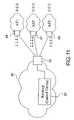
- FIG. 11is a functional block diagram providing a first computer network and routing peers associated with the first computer network.
- Table 12provides, for didactic purposes, a network prefix dataset, including the paths corresponding to each network prefix, segregated into a plurality of interleave groups.
- FIG. 13is a flow chart diagram setting forth a method directed to the identification of a target intermediate system in a path to a destination network.
- FIG. 14is a flow chart diagram illustrating an interleaved route injection and testing method according to one embodiment of the present invention.
- FIG. 15is a flow chart diagram providing a method associated with testing a path to a destination network.
- routing control device 20that can be deployed within a network environment and used to manipulate routing policy implemented by routing systems 30 (e.g., applying path preferences to routing systems).
- the routing control device 20is an Internet appliance and, in some embodiments, routing control device 20 obtains routing path information and modifies the operation of associated routing systems 30 .
- a central server 40 in connection with a plurality of data collectors 90obtains path information for use by one or more routing policy control devices 20 (see FIG. 2 ).
- the functionality described hereincan be deployed in a variety of configurations from stand-alone Internet appliances to centrally and virtually managed services.
- FIG. 1illustrates a computer network environment including an embodiment of the present invention.
- the computer network environmentincludes autonomous systems 52 and 54 , each of which are a single network or a collection of networks under a common administrative policy and registration.
- routing control device 20is operably coupled to at least one routing system 30 within a customer autonomous system 80 .
- the computer network environmentin one embodiment, also includes routing control center 25 providing a centralized point of administration and/or access to one or more routing control devices 20 .
- routing control device 20operates in connection with routing control device database 24 .
- Routing control device database 24may be an integral part of routing control device 20 or, in other forms, may reside in a separate database server.
- routing control device database 24includes routing control device configuration data, configuration policies, routing system rule sets, and test results (e.g., routing path metrics and/or traffic data).
- routing control device database 24includes routing system profiles for each routing system connected to routing control device 20 .
- FIG. 2illustrates a system providing a centralized source for Internet routing policy.
- the systemin one embodiment, comprises a central server 40 operably connected to a plurality of data collectors 90 within an autonomous system 80 . Although only one autonomous system 80 is shown, sets of data collectors 90 may be deployed on multiple autonomous systems, respectively. Operation of the central server 40 and the data collectors 90 is described in more detail below.
- a routing system 30is any machine capable of routing data between two networks and sharing network layer reachability information between one or more routing systems.
- routing systems 30share network layer reachability information via BGP.
- the usermay add routing systems 30 to routing control device 20 by supplying the IP address or fully qualified domain name of a primary interface and access authority information for the routing system ( FIG. 3 , step 204 ).
- routing control device 20may import a set of routing systems from an external source or via a system discovery protocol ( FIG. 3 , step 206 ).
- a primary interfaceis one that has a known IP address or a fully qualified domain name assigned for the duration of the life of the routing system.
- Access authority informationusually consists of a user name, password combination but may contain other necessary information for a specific authentication protocol and should be supplied for each type of access method supported by routing control device 20 (see step 202 ). Access methods include Simple Network Management Protocol (SNMP) queries, interactive sessions to terminal interfaces, and other proprietary access protocols.
- the routing system 30is initially probed using the supplied access method to determine system wide parameters such as make and model of the routing system ( FIG. 3 , step 208 ). The routing system 30 may be probed using multiple access methods as required to obtain the system wide parameters. After all routing system responses have been collected, a routing system profile consisting of the user supplied information combined with probe responses is stored in routing control device database 24 ( FIG. 3 , step 210 ).
- Routing control device 20includes a predefined or default routing policy configuration, called the default device configuration policy.
- the default routing policy configurationis stored in routing control device database 24 .
- This set of routing policiesdefines a default configuration rule set that determines how inter-domain routing should be configured based on current industry best practices. All actions routing control device 20 makes are directly or indirectly based on this default configuration rule set.
- the usercan update the default device configuration policy periodically by querying a central server (e.g., such as a server located at routing control center 25 ) and downloading the latest default device configuration policy, if desired.
- the usercan further modify the default device configuration policy to apply customized network wide configuration parameters by supplying the requested policy as a local configuration policy that is input to routing control device 20 using a graphical interface, a configuration file, or a command line interface.
- This local configuration policyis checked for errors based on the specifications of the default device configuration policy.
- the local configuration policyis then saved in routing control device database 24 , over-writing any previously saved local configuration policies.
- Each time routing control device 20 is powered on itreads the local configuration policy from routing control device database 24 and if it exists, combines it with the default configuration policy. This combined policy becomes the primary configuration policy for routing control device 20 .
- a usermay specify a local configuration policy for each routing system 30 ; routing control device 20 therefore generates a primary configuration policy for each routing system 30 .
- Routing control device 20enforces the primary configuration policy on any routing system 30 for which it is requested to control. When a routing system is added, routing control device 20 checks the routing system rule set for inconsistencies with the primary configuration policy and changes the routing system rule set to be consistent with the primary configuration policy for routing control device 20 .
- routing system 30must be configured. Subsequent changes in the primary device configuration policy may also require the routing system 30 to be reconfigured. To do this, the user specifies the routing system(s) 30 to be configured ( FIG. 4 , step 302 ). Query methods and access authority information are retrieved for the corresponding IP addresses or fully qualified domain names from routing control device database 24 (step 304 ). Routing control device 20 then queries the routing systems 30 to assemble a current routing system configuration for each routing system 30 using the appropriate query method (step 306 ). The retrieved routing system configuration is interpreted to define the current BGP peering setup as a rule set per routing system called a system rule set (step 308 ).
- This system rule setincludes the entire data set of configuration information for the peers such as IP addresses, autonomous systems, filters, descriptions, and peering options. If the retrieved system rule set is in conflict with the primary device configuration policy of routing control device 20 , routing control device 20 logs an error, fixes the system rule set (step 312 ), and applies the updated system rule set to the routing system 30 (step 314 ). The finalized system rule set is stored in the routing control database 24 for later retrieval (step 316 ). Parameters in the system rule set may be translated into user-friendly names using a proprietary database of information. For example routing control device 20 may map autonomous system numbers to network names.
- Routing control device 20retrieves access authority information and system rule sets from routing control device database 24 (step 404 ). Routing control device 20 removes all references to the routing system from the local configuration policy (step 406 ), if any exist, and re-runs the verification routines on the resulting local configuration policy (step 408 ). If the new local configuration policy passes the verification process, any reference to peers and system parameters for the removed routing system are removed from routing control device database 24 . The user may request the system rule set for the deleted routing system to continue to be stored in routing control database 24 for future use after being marked as inactive by routing control device 20 (see steps 414 and 418 ).
- routing control device 20removes it from the routing control device database 24 (step 416 ). The user may request that routing control device 20 remove all corresponding configurations from the routing system (see step 410 ). If so, routing control device 20 will generate the necessary configurations from the existing system rule sets before they are deleted from routing control device database 24 (step 412 ). Routing control device 20 will then use the default access method to remove the routing configurations from the routing system before continuing.
- routing control device 20configures the peering relationships associated with the routing system in order to apply the primary routing policy configuration.
- routing control device 20The user must supply a nominal amount of information to have routing control device 20 configure a new peer (e.g., an inter-domain peer or internal peer) or modify an existing one.
- a new peere.g., an inter-domain peer or internal peer
- the userprovides routing control device 20 with the name of the routing system 30 being configured and the IP address of the peer (e.g., inter-domain peer 60 or 62 or internal peer 34 ) ( FIG. 6 , step 502 ).
- the usercan supply routing control device 20 with additional policy requirements for this peer such as peer-specific filtering or transit parameters.
- the peering configuration state on the routing system 30is compared with the last known good peering configuration saved in the routing control device database 24 , if one exists, to ensure consistency and to detect any non-routing-control-device- 20 -introduced changes.
- step 506retrieves the current peering configuration from the routing system 30 (step 506 ), translating it into a system rule set, and comparing it to the version stored in routing control device database 24 (see steps 504 and 508 ). If the system rule sets do not match (step 508 ), a warning is issued (step 510 ) and by default the action is aborted. However, the user may specify that if the retrieved system rule set does not match the stored system rule set, routing control device 20 should overwrite the existing configuration using the new stored system rule set (step 512 ). Once the system rule sets have been compared, the user supplies data explaining the desired policy outcome by responding to questions from a predefined template (step 514 ).
- This datais combined with the previously stored system rule set to generate an inclusive view of the desired routing policy for that peer (step 516 ).
- This inclusive system rule setis interpreted against the primary configuration policy and formatted to generate the new peer configuration.
- the completed rule setis verified for consistency with network wide policy and translated to the proper configuration nomenclature for the routing system (step 518 ).
- routing control device 20will use the previously stored default access method for the routing system to apply the new configuration (step 522 ).
- the userhas the option, however, of overriding this step and choosing to apply the configuration generated by the routing control device 20 manually to the routing system.
- the old system rule setis replaced with the new one in routing control device database 24 (step 524 ).
- Routing control device 20retrieves access authorization information from routing control device database 24 (step 604 ), queries the routing system using the default access method to retrieve the current peering configuration from the routing system (step 606 ) and translates it into a system rule set. Next, the peer's retrieved rule set is analyzed for compliance with the primary configuration policy (steps 608 and 610 ).
- routing control device 20stores the system rule set in routing control device database 24 (step 616 ).
- Routing control device 20will retrieve the existing system rule set for the peer from routing control device database 24 and use it to generate the configuration necessary to remove the peer from the routing system. Routing control device 20 uses the default access method for the routing system to apply the configuration and remove the peer. Finally, any data for the peer is removed from the system rule set and the resulting system rule set is stored in the routing control device database 24 .
- the peer configurationcan be retained in the system rule set in routing control device database 24 for future use by being marked as inactive.
- Routing control device 20may be deployed in a number of different manners for different purposes. Routing control device 20 may be deployed as a single standalone unit for operation in connection with one or more locations. Multiple devices may be deployed at a single location or at multiple locations to serve in a redundant fashion. If more than one device is talking to a routing system, the routing control device with the lowest IP address injects the best route into the routing system in accordance with BGP protocol. The priority of additional routing control devices is determined by the increasing magnitude of IP addresses.
- routing control device 20acting as the server identifies and locates the client devices and provides the clients with a set of policies as established on the server device for those locations.
- Routing systems 30 requiring traffic engineering functionalitymust be peered with routing control device 20 using an Internal Border Gateway Protocol (IBGP) session called a control peering session.
- the control peering sessionis the BGP4 peer relationship between the routing system 30 and the routing control device 20 used to update the routing system 30 with traffic-engineered routes.
- routing control device 20is peered to all routing systems 30 serving as egress points from the customer network or autonomous system 80 . Multiple devices located at multiple egress points from the customer network may work together and share a common routing control device database 24 (not shown). A single IP address assigned to routing control device 20 is to be used as the neighbor address for all control peering sessions.
- Routing system 30should supply a unique and static IP address as the preferred BGP neighbor address for establishing the control peering session between it and the routing control device 20 .
- the usercan configure a standard inter-domain or IBGP peering session for the purposes of traffic engineering by supplying routing control device 20 with information that is a unique identifier for the peer on the routing system 30 .
- Routing control device 20will generate a system rule set based on the primary configuration policy and apply it to the routing system 30 using the default access method.
- the userspecifies the inter-domain or IBGP peer on the routing system by supplying a unique identifier.
- Routing control device 20will retrieve the current system rule set, generate a routing system configuration to remove the inter-domain or IBGP peer, and apply the configuration to the routing system 30 based on the default access method.
- routing control device 20controls routing in a routing system 30 by injecting routes with better metrics than the ones installed locally. Metrics used include local-preference, weight, multi-exit discriminator, and/or others as defined by the BGP protocol.
- the routing system 30interprets these routes and installs them into its local routing table as long as the control peering session is active.
- An adjacency-Routing Information Base-inis the total set of routes the routing system 30 receives from all BGP speakers, including routing control device 20 and all other BGP peers.
- routing control device 20must monitor the adjacency-RIB-in on the routing system 30 to insure the destination peer specified by the traffic engineered route maintains network layer reachability (steps 704 and 706 ). This may be done by polling the routing system using the default access method or by monitoring the unadulterated BGP update messages from each destination peer.
- routing control device 20must immediately withdraw its corresponding traffic engineered route for this destination as well (step 708 ). Routing control device 20 should then inject a new traffic engineering route by selecting the next best destination peer after verifying that the destination peer still exists in the adjacency-RIB-in and waiting for a predefined hold down time (steps 710 and 712 ). Routes that are withdrawn from the routing control device 20 RIB start collecting a penalty that is reduced over time by using the exponential decay algorithm described in RFC2439. Once the half-life has been reached in the decay period, the previously withdrawn route can be used again (see step 714 ). Routing control device 20 can then reevaluate all potential destination peers, selecting the best route and inject a traffic engineered route into the routing system 30 .
- the usercan define the frequency with which routing control device 20 controls routing updates being injected into the routing systems by supplying an interval timer for traffic engineering methods. If the user does not supply a metric for a given method, a default will be used. The default timer is based on the update period that achieves the best network stability for that traffic engineering method. Since routing control device 20 is simply a BGP peer using the standard protocol, if the peering session between routing control device 20 and the routing system 30 fails all modified routes are flushed from the routing system RIB.
- routing control device 20can request that routing control device 20 actively load share traffic across multiple inter-domain peers by supplying information that uniquely identifies each peer and a minimum utilization threshold at which the process should begin (see FIG. 9 , step 814 ).
- the usermay specify a maximum threshold at which load sharing ceases (see step 816 ).
- routing control device 20determines the active traffic load by directly sampling traffic flows from the network, by accepting sampling data from other systems, or by other deterministic or non-deterministic methods and stores the ordered results in the routing control device database 24 . Traffic-sampling data is analyzed to generate the total amount of traffic per destination network (see step 804 ).
- routing control device 20queries the routing system 30 using all necessary access methods (as described in 1.1.1) to monitor network utilization (see steps 808 , 810 and 812 ).
- routing control device 20loads the sorted list of top traffic destinations from the routing control device database 24 (step 818 ). In the absence of sampling traffic or data, routing control device 20 alternates destination networks based on a heuristic designed to choose the most likely candidates for large traffic flows. Using the primary configuration policy, routing control device 20 load shares traffic based on available routing system resources. An ordered set of inter-domain peers to be balanced is generated from the IP addresses supplied by the user (step 806 ). In one preferred form, the first element of the set is the active peer for the largest destination network.
- the results from a load sharing algorithmare used to select the destination peer for each network (see steps 834 , 836 , 838 and 840 ).
- the destination network's current traffic load figuresare subtracted from its present destination peer's total traffic load figures (step 824 ).
- the destination networkis then compared to each destination peer in the set in turn until a suitable path is found or the entire set has been traversed (see steps 828 , 834 , 836 , 838 and 840 ).
- the first destination peer in the setis chosen (step 834 ) and the network is verified to be reachable through it (step 836 ).
- the destination peer's current traffic loadis verified to insure sufficient bandwidth is available to handle the additional burden of the destination network (step 840 ). If the bandwidth is available the destination peer is chosen as the best path (step 842 ). If neither of these expectations are met, the next destination peer in the set is analyzed against the network using the same methods (step 838 ). The process is repeated for the destination network until an available peer can be found or the entire set has been traversed (see step 828 ). If no suitable destination peer is found, then the destination peer with network reachability and the greatest available bandwidth is chosen (step 830 ).
- the networkis routed over that peer by injecting a BGP route update into the routing system 30 with the next hop field set to the destination peer's address, using techniques as described in section 1.2.2.
- the peer setis then reordered so that the chosen peer becomes the last available element in the set and the next destination peer becomes the first available element in the set (step 826 ). This process is repeated for each destination network in the list up to the user-defined limit (see steps 820 and 832 ).
- the actual load balancing routinesonly run at predefined or user defined intervals. Additionally, a user may supply a local configuration policy to define how traffic is balanced between inter-domain peers. If the minimum or maximum thresholds are attained, any previously balanced networks will be maintained in the routing table, but no new networks will be injected for load sharing purposes.
- the usercan request routing control device 20 to route traffic based on metrics alternative to the standard BGP protocol metrics.
- the usersupplies routing control device 20 with a set of destinations to test ( FIG. 10 , step 902 ).
- This setmay be defined as individual destinations using names, IP addresses, URLs or other host identification tags or it may be defined as a sequential list of networks.
- a destination setmay be a local user defined list, may be supplied by an external source, or may be generated by routing control device 20 using traffic analysis similar to the method described in section 1.2.4, above.
- routing control device 20must determine what peers have network layer reachability to the destination networks by examining the adjacency-RIB-in on the routing system 30 (steps 904 and 906 ). Routing control device 20 then builds a set of possible destination peers based on this information and tests each in sequence.
- Routing control device 20has three options for determining the best path to a destination network: 1) routing control device 20 may test performance metrics itself (step 908 ), 2) it may request that the routing system test performance metrics (step 924 ), or 3) routing control device 20 may query a central location containing a set of performance metrics (step 926 ) [see section 2.2.1, infra]. For routing control device 20 to test network blocks internally without affecting the current traffic flows to the destination, routing control device 20 first finds the corresponding network route for a host in the destination set and identifies a list of all possible destination peers for that network route. The route entry contains enough information for routing control device 20 to determine the broadcast address for the destination network.
- Routing control device 20then injects into the routing system 30 being tested a host route (i.e., a network route with an all-one's network mask) to the broadcast address of the destination network with a next hop of the first destination peer in the previously identified list of possible destination peers (step 910 ). Routing control device 20 runs performance tests on the path through that peer. The results are stored in routing control device database 24 for trending purposes and the process is repeated for the next destination peer (step 912 ). After all possible paths have been tested a best path is chosen based on the performance metrics.
- a host routei.e., a network route with an all-one's network mask
- routing control device 20For routing control device 20 to test metrics from within the routing system 30 , routing control device 20 queries the routing system 30 with the default access method and uses the available routing system tests such as the TCP/IP ping or traceroute facility to determine best path by sourcing the tests through each destination peer in sequence (step 914 ). The results are stored in routing control device database 24 for trending and a best path is chosen. Finally, routing control device 20 may query a central server by first testing the metrics from routing control device 20 to the data collectors 90 associated with a central server 40 (step 916 ) and then supplying the central server with the set of destination networks or hosts to be tested (step 918 ).
- routing control device 20queries the routing system 30 with the default access method and uses the available routing system tests such as the TCP/IP ping or traceroute facility to determine best path by sourcing the tests through each destination peer in sequence (step 914 ). The results are stored in routing control device database 24 for trending and a best path is chosen. Finally, routing control device 20 may query a central server by first testing
- the central server 40determines the best path based on the results of tests previously run from a central location, such as to the destination networks combined with the results of the path tests between routing control device 20 and a data collector 90 associated with the central server 40 . (See Section 2.2, infra, and FIG. 2 .)
- best pathis determined by attempting to characterize the performance of the path through each destination peer. This performance is gauged on a weighted aggregate of the results of a series of tests, which may include any of the following factors: 1) response time, 2) hop count, 3) available bandwidth, 4) jitter, 5) throughput, and 6) reliability.
- the path performance metric generated by the central server 40 and data collectors 90can be used as merely another test that is weighted and aggregated with other tests in selecting the best path to a given destination. Since the function of the tests is simply to determine best path, new methods may be added in the future by simply defining the test method and adding the weight of the results to the scale.
- routing control device 20injects a route for the destination network into the routing system 30 with the next hop set to the address of the selected destination peer using techniques as described in section 1.2.2 (see steps 920 and 922 ).
- an expanded set of performance testsmay be performed between two or more routing control devices at different locations.
- routing policycan be engineered for data traversing between those locations.
- routing control devices 20perform a closed loop-test between each other. The closed-loop test runs by injecting host routes to the IP address of the remote routing control device with the next hop set to each potential destination peer in their respective routing systems. This method of testing allows routing control devices 20 to gather a greater amount of information since the flow of traffic can be controlled and analyzed on both sides of a stream. This method of testing is accomplished, in one form, using only routing control device resources.
- Routing control device 20employs enhanced testing methodologies that maximize the likelihood of receiving responses to test packets.
- Embodiments of the enhanced testing methodologies described hereinfeature one to three components. First, as to a given path, routing control device 20 probes the path to locate and define the characteristics of a target intermediate system for subsequent use by path metrics test modules. A second component involves the interleaved injection and testing of routes to reduce the time required to perform metrics tests on the paths associated with a given set of network prefixes. Lastly, the metrics test modules themselves incorporate checks to determine whether the properties of the previously defined path are still valid, or whether such path properties require re-computation.
- a preliminary step associated with testing paths to destination networks in relation to at least one metricis the definition of a target intermediate system for each path.
- routing control device 20After routing control device 20 has identified a target intermediate system for a particular path, it stores the IP address of the intermediate system and the number of hops to the intermediate system in association with a path identifier. In subsequent testing of the path, routing control device 20 , in one embodiment, tests to the target intermediate system, as discussed more fully below, and analyzes the responses, if any, to the test packets to determine whether the properties of the path and target intermediate system should be recomputed.
- the target selection process for a pathis performed only if no target intermediate system has been previously identified for a particular path or the execution of the metrics tests achieves an invalid result (see below). For example and in one embodiment, assuming target intermediate data is not stored persistently, routing control device 20 performs the target selection process upon start up or re-initialization. In addition, routing control device may also perform the target selection process as required for previously undefined paths before execution of the interleaved route injection and testing process discussed below.
- the goal of the target selection phaseis to determine the properties of the path and the target intermediate system.
- routing control device 20uses hop-limited UDP packets configured to expire at the target intermediate system to determine individual path metrics. Accordingly, target selection allows for a determination of the hop on which to limit the test packets and the IP address from which responses should emanate.
- routing control device 20can inject a host route to a particular destination network host corresponding to the path and employ a conventional traceroute utility (see below) directed to the destination network host to characterize the path and identify the target intermediate system.
- routing control device 20identifies the target intermediate system by injecting host routes to the broadcast address of the destination network prefix and transmitting a series of hop-limited probe packets to the broadcast address of the destination network prefix.
- the IP protocoluses the Time to Live (TTL) field to limit the distance a packet may travel before it expires and is discarded.
- TTLTime to Live
- the TTL field in an IP packet headeris decremented by one for each intermediate system the packet passes through.
- ICMPInternet Control Message Protocol
- a packet sent with a TTL value of threewould be able to traverse three intermediate systems before expiring or “timing out.”
- the third intermediate systemwould discard the packet and send an ICMP response back to the sender.
- the sendercan then determine the address of the third intermediate system by analyzing the source IP address of the ICMP response packet.
- Information included in the payload of the outbound test packet(s), and therefore in the payload of the ICMP response,allows the sender to send many different packets and still correlate unique outbound packets with inbound ICMP responses.
- Van Jacobsenuses hop limited probes and the characteristics of the IP protocol to define a utility called traceroute that can determine the path a packet takes to reach a destination. See Van Jacobsen, “Traceroute” (1988).
- the traceroute utilityuses UDP packets sourced from unique source port, destination port pairs where the destination ports are high number ports not likely to be in use on the remote end system. If a port is not in use on an end host, the host will return an ICMP “port unreachable” response if it receives a packet on that port. The port information is returned in an ICMP packet and can therefore be correlated to an individual test.
- traceroutesends a series of packets where each succeeding packet's TTL value is incremented by one.
- the traceroute utilityanalyzes the “ICMP TTL expired” responses to determine the IP address of the intermediate systems in the path. For example, the source address of the ICMP response that corresponds to the UDP packet with a TTL of one is the IP address of the first hop in the path, and so on.
- the traceroute utilityknows it has reached the target host when it receives an ICMP “port unreachable” packet from the end host.
- routing control device 20uses a modified version of the traceroute utility discussed above to ensure that legitimate network traffic remains unaffected by the metrics test process.
- FIG. 13sets forth a method allowing for the selection of a target intermediate system for a given path.
- the target selection processinvolves transmitting hop-limited probe packets to the broadcast address of the destination network ( 1102 ).
- the routing control device 20beginning with a TTL value of 1 ( 1104 ), utilizes two UDP packets per TTL value to allow for detection of per-packet load balancing, redirects and network loss ( 1106 ).
- the probe packetsare User Datagram Protocol (UDP) packets; however, other IP packet types can also be used, such as TCP packets. Since the probe packets are sent to the broadcast address associated with the network prefix, routing control device 20 can not expect to consistently receive a “port unreachable” or other ICMP type code three response allowing it to explicitly determine that the last intermediate system in a given path has been reached and to terminate the probing sequence. Since there is no guaranteed error response packet, routing control device 20 terminates the transmission of probe packets, if it receives any kind of ICMP type three response to any single UDP packet probe with any TTL ( 1112 ) or no response to two consecutive UDP packet probes with the same TTL ( 1108 ).
- UDPUser Datagram Protocol
- routing control device 20After routing control device 20 transmits two UDP probe packets for a given TTL, it waits for ICMP responses, if any, to the probes. If routing control device 20 does not receive a response to either probe packet ( 1108 ) within a threshold period of time (e.g., 5 seconds), it terminates the probing sequence.
- a threshold period of timee.g., 5 seconds
- the timeout periodis a configurable parameter.
- routing control device 20If routing control device 20 receives two responses, it compares the source IP addresses of the ICMP responses to determine whether they are the same ( 1110 ). If the ICMP responses were sourced from different intermediate systems, routing control device 20 marks the path as being multi-pathed ( 1111 ), stores the IP address(es), ICMP type code, and TTL value associated with the response(s) ( 1114 ). If only one response is received, routing control device 20 assumes a network loss as to the remaining probe packet, bypasses a comparison of the source IP addresses of the ICMP responses, and, assuming the response is a TTL expired response, stores the IP address(es), ICMP type code, and TTL value associated with the response(s) ( 1114 ).
- the ICMP response type(s)are analyzed ( 1112 ). If the ICMP response type is a “TTL expired” response (Type 11), routing control device 20 increments the TTL value for the probe packets ( 1116 ) and continues the probing sequence. Otherwise, routing control device 20 discontinues the probing sequence. Routing control device 20 , however, stores the ICMP type code of the response that triggered termination of the probing sequence (the terminating response) ( 1118 ).
- routing control device 20After terminating the successive transmission of probe packets with incremented TTL values, routing control device 20 chooses the last non-repeating hop and stores the TTL and IP address associated with the chosen intermediate system.
- a repeating hopis an intermediate system that responds to two or more UDP packet probes that were initially transmitted with different TTL values. This usually indicates a routing loop and is likely to happen with the target selection process described herein, as the packets are destined for broadcast addresses.
- routing control device 20removes from the list of IP address-TTL pairs generated during the probe transmission process all duplicate IP addresses ( 1120 ). In the case where an IP address is associated with more than one TTL value, the IP address-TTL value pair having the larger TTL value is removed. Routing control device 20 then selects the intermediate system/IP address associated with the largest TTL value ( 1122 ).
- routing control device 20executes certain validity tests based on the route information available to it. If the terminating ICMP response was a host unreachable error (ICMP type 3 code 1) ( 1124 ), then routing control device 20 assumes that it has reached the end of the path and uses the selected intermediate system as the target intermediate system for subsequent testing of the path. If the type of the last ICMP packet offers insufficient information as to the termination point of the path, however, then routing control device 20 resorts to route information in the BGP tables to validate the selected intermediate system. As FIG.
- routing control device 20finds the BGP route matching the network prefix corresponding to the broadcast address used in the probe packets and analyzes the AS path to identify the last and second-to-last AS in the path ( 1128 ). By BGP convention, the last AS in the path is the AS that sourced the network prefix. Routing control device 20 also finds the BGP route matching the IP address that was determined to be the last non-repeating hop ( 1126 ).
- routing control device 20can determine that the last non-repeating hop IP address is at least in the administrative domain of the prefix ( 1130 ) and uses the last non-repeating hop as the target intermediate system for subsequent metrics tests. If the source AS of the BGP route corresponding to the last non-repeating hop matches the second to last AS in the network prefix AS path, then routing control device 20 assumes the last non-repeating hop is associated with the provider to the administrative domain of the network prefix and uses the last non-repeating hop as the target intermediate system in subsequent metrics tests. If none of these cases are met, then routing control device 20 assumes a failure and tries to re-compute path properties ( 1132 ).
- routing control device 20tests each possible network path to the set of network prefixes using a predetermined set of metrics tests. Routing control device 20 , in one embodiment, accomplishes this by injecting a host route matching the broadcast address of the network prefix into the local BGP domain and executing the set of metrics tests to the broadcast address, as discussed below. Routing control device 20 then repeats this process for all paths to the network prefix. Specifically and in one embodiment, each injected route has NLRI set to a single available nexthop.
- routing control device 20will inject a route to 10.0.0.255/32 with a nexthop of 1.1.1.1 and wait for the route to propagate through the local BGP domain. Once the route has propagated through the local BGP domain, routing control device 20 tests the path through peer A 66 by sending test packets with a destination address of the broadcast address of the network prefix being tested.
- a given network prefixe.g., 10.0.0.0/24
- routing control device 20After testing of the particular path is completed, routing control device 20 stores the results in a database, and injects a new host route for 10.0.0.255/32 with a nexthop of 2.2.2.2. Again, routing control device 20 executes the metrics tests and stores the results for the second path. Routing control device repeats this process for all possible network paths to the network prefix, making sure to withdraw the last-injected host route for the network prefix.
- Routing control device 20uses an interleaved route injection and testing method to ensure enough time passes for injected test routes to propagate throughout the local BGP domain, before conducting path metric tests using such host routes.
- routing control device 20segregates unique network prefixes into two or more groups and sorts the set of test routes by both the corresponding network prefix and grouping of network prefixes (See, e.g., Table 12 and discussion below).
- the number of prefixes allocated to each groupis determined by dividing the total number of network prefixes to be tested by the number of concurrent testing resources available. In another embodiment, the number of network prefixes in each group is determined by a configurable parameter limited by the number of concurrent testing resources.
- Routing control device 20injects a set of routes from a first group of network prefixes before testing a previously injected set of routes from a previous group.
- This techniqueallows for injected routes to propagate throughout the BGP domain during the natural time delay associated with execution of the metrics tests on a set of previously injected test routes. As FIG. 14 shows, this is accomplished by injecting the routes for the next interleave group before initiating the metrics tests on the current group. For example, if routing control device 20 is testing ten unique prefixes with two paths each, routing control device 20 , in one embodiment, may divide the network prefixes into two groups of five network prefixes.
- Routing control device 20waits for a small period of time to allow these first set of routes to propagate. Although certainly contemplated by some embodiments of the present invention (above), continually waiting for route propagation before testing is suboptimal; so, before testing the paths just inserted, routing control device 20 inserts the next group of prefixes to their respective first paths as well. Therefore, the time spent testing the paths in the first group allows the paths for the second group to propagate in time for the metrics test to be run on the second group.
- routing control device 20verifies that the last route in a group has propagated by using Simple Network Management Protocol (SNMP) to query the routing table of the routing device 30 through which the test packets ultimately egress.
- SNMPSimple Network Management Protocol
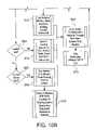
- FIG. 14sets forth a method that interleaves injection of test routes and the testing of previously injected routes according to an embodiment of the present invention.
- routing control device 20retrieves the network prefixes to be engineered ( 1002 ) and fetches the paths to the network prefixes obtained from NLRI information ( 1004 ).
- routing control device 20determines whether a target intermediate system has been previously defined for each path and, if not, executes the target selection process for such paths. Routing control device 20 then segregates the network prefixes into two or more groups ( 1006 ).
- the number of network prefix groupsis determined by dividing the number of network prefixes by the number of available sockets (which is limited by the operating system kernel or, artificially limited to a smaller number to conserve resources (e.g., 200 sockets)). For example, 1000 network prefixes and 200 available sockets would result in 5 network prefix groups.
- Table 12sets forth an exemplary grouping of network prefixes. As Table 12 illustrates, the network prefixes have varying numbers of network paths. Each path in a particular group corresponds to a path set. For example, Group 1 includes three levels of path sets with the lowest level path set including a single path (Path 3 ).
- routing control device 20injects a test route for the first set of paths in the first group ( 1010 , 1012 , 1014 ) and, in one embodiment, waits for a small period of time to allow for propagation of the injected routes throughout the BGP domain ( 1016 ). Routing control device 20 then injects a first set of test routes for the second interleave group ( 1018 , 1020 ). Routing control device 20 , starting with the first network prefix in the first interleave group ( 1022 , 1024 ), then tests the path as discussed below ( 1028 ). Routing control device 20 , in one embodiment, first determines for the given path set level, whether there is a path associated with the network prefix ( 1026 ). As FIG.
- routing control device 20tests each path in the current interleave group and path set ( 1030 , 1032 ). Routing control device 20 then proceeds to the second group ( 1034 , 1036 ), but first injects test routes for the subsequent group ( 1038 , 1018 , 1020 , 1040 , 1042 , 1044 , and 1046 ). Routing control device 20 progresses through the groups in a circular fashion changing the path set level at each full cycle through the interleave groups (see 1034 , 1050 , 1052 ) until all routes have been tested.
- routing control device 20tests paths to a given network prefix by sending test packets addressed to the broadcast address associated with the network prefix.
- Using the broadcast address as the destination of metrics testsallows routing control device 20 to inject routes into the BGP domain that will not affect normal traffic flows while still making it possible for the tests to be preformed on each path.
- the broadcast addressis normally used only by systems local to the network for administrative purposes. Since routing control device 20 tests remote networks, it can safely change the routing of this single address in the local BGP domain because there should be no legitimate network traffic destined for a remote broadcast address.
- Test modules implemented by routing control device 20send a series of hop-limited UDP packets sent to the network prefix's broadcast address to determine path characteristics.
- the test modulesmay use the computer network address of a destination network host, use of the broadcast address is preferred as the injection and testing of routes using the broadcast address ensures that legitimate network traffic remains unaffected.
- the test packetsare configured to expire at the target intermediate system previously identified during a target selection process. In an IP network environment, this can be accomplished by setting the TTL value of the test packets to the number of hops to the target intermediate system. In one embodiment, the hop number on which to expire the test packets and the expected IP address of the response are determined by a previously executed target selection process, discussed above.
- routing control device 20is more likely to receive an ICMP error response since intermediate systems are required by RFC1812 to respond to a TTL timeout.
- hop-limited test packetsreduce the perception that the packets are associated with intrusive or suspicious activities since packet expiration is usually processed by a system before other packet validity checks that would report the error, such as those done by a firewall or an application layer process. For example, a hop-limited test packet expiring at a network gateway triggers an error at a lower level process in the IP stack of the gateway. Accordingly, the gateway drops the packet and responds with a TTL expired ICMP response. The packet never reaches a firewall process or other application that operates in connection with higher levels of the protocol stack associated with the gateway and that would trigger and alarm due to the error, or would prevent transmission of a response.
- Test modulescan calculate any number of different types of industry standard measurements, such as latency, jitter, loss or available bandwidth, by varying the size of the test packets and/or the quantity transmitted. Results are computed for each path and are stored by routing control device 20 for future path comparisons. However, if the path changes after the target selection phase has completed, the results of the metrics test will be invalid. Therefore, if the metrics tests detect a path change the results for the current tests should be invalidated and the target selection process should be re-initiated.
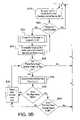
- FIG. 15sets forth a method associated with metrics testing to determine whether the characteristics of the target intermediate system in a given path should be recomputed.
- One way metrics tests can detect a path changeis by analyzing the source IP address of the ICMP error response ( 1204 ). If the source address of the error packet is different from the previously computed source address then the metrics test knows the path has changed and requests that the target selection process recompute the path properties ( 1210 ). Also if the ICMP type of the response packet is not of ICMP type 11, TTL expired, then the path has changed and will need to be recomputed ( 1206 ). A metrics test will also request that the target selection process recompute path properties, if routing control device 20 does not receive any ICMP error packets for all the probes it sends in a given measurement cycle ( 1208 ).
- routing control device 20injects a route for the destination network into the routing system 30 with the next hop set to the address of the selected destination peer using techniques as described in section 1.2.2.
- the usercan initiate traffic engineering based on the time of day by specifying an action, a time, and, in some embodiments, a destination set.
- the actionmay be procedural or specific depending on the desired outcome.
- a procedural actionis one that deals with the overall routing policy in routing control device 20 .
- routing control device 20cease traffic engineering for all destinations between 1 AM and 2 AM.
- a specific actionis one that deals with a predefined set of destinations that are supplied by the user.
- the usermay request that a set of destinations use peer A during business hours and peer B at all other times. Routing control device 20 identifies and attempts to resolve inconsistencies between multiple time-of-day policies. Once valid time-of-day engineering is determined, routes that conform to the policy are injected using techniques as described in section 1.2.2.
- Explicit traffic engineeringallows the user to explicitly set a policy regardless of peer load or path metrics. For example, the user can specify that all traffic to a destination network always exit through a given peer. After verifying that the route has valid network layer reachability through the destination peer, routing control device 20 will inject a route for the network with the next hop set to the destination peer. If the peer does not have reachability to the network, routing control device 20 will not inject the route unless the user specifies that the policy is absolute and should not be judged based on network layer reachability. Explicit traffic engineering routes are injected into the routing system(s) 30 using techniques as described in section 1.2.2.
- Part of the primary configuration policydefines how local network announcements are made to other autonomous systems. These announcements influence the path ingress traffic chooses to the set of local networks and routing systems for the user's autonomous system. If a user wishes to modify network advertisements in order to influence inbound path selection, the local configuration policy is defined so as to modify outbound route advertisements to inter-domain peers. Modifications to the outbound route advertisements include BGP techniques such as Multi-Exit Discriminators (MEDs), modification of the AS Path length, and network prefix length adjustment selected from a template of available modification types.
- MEDsMulti-Exit Discriminators
- This local configuration policyis uploaded as part of the primary routing configuration policy as described in section 1.1.3.
- routing control device 20allows for more granularity in load sharing and other traffic engineering processes than otherwise available using standard Network Layer Reachability Information (NLRI).
- BGP updates for a given network prefixmust contain a valid network layer reachability information (NLRI) field. Routing control device 20 uses the information in the NLRI field to determine to where traffic flows destined for a given network prefix are capable of being routed.
- routing control device 20operates on the assumption that, if a parent network is reachable via a given nexthop, all subnets of that parent should be reachable via the same nexthop. Routing control device 20 uses this concept called soft NLRI (SNLRI) to enhance various traffic engineering processes discussed herein.
- SNLRIsoft NLRI
- routing control device 20When traffic engineering, routing control device 20 , by default, inserts routing updates to match the originally advertised prefix of the network, as it exists in the local BGP table. However, the larger the prefix the less accurate any performance measurement or load sharing decision will be due to the increased number of hosts in the prefix. In order to be more accurate in performance based (see Section 1.2.5) or load sharing routing updates, a network administrator may configure routing control device 20 to engineer routes based on a specified network mask size, as opposed to the network masks associated with standard NLRI address information. In one embodiment, routing control device 20 may effectively increase the network mask size of a given prefix by injecting routes associated with a single or multiple soft NLRI (SNLRI) subnets of the network prefix being engineered.
- SNLRIsoft NLRI
- routing control device 20applies certain rules when engineering SNLRI routes.
- Each SNLRI subnet of a given network prefixmay have different nexthop information as long as there exists a corresponding parent route with the same nexthop in the BGP table of routing control device 20 .
- a SNLRI routemay not be injected if a more specific naturally occurring NLRI subnet route with the same prefix and mask length as the engineered SNLRI route already exists in the routing table.
- routing control device 20engineering SNLRI routes for a network prefix of 192.168.0.0/16 down to a /17 network mask (breaking the prefix into SNLRI prefixes of 192.168.0.0/17 and 192.168.128.0/17), first determines whether a naturally occurring NLRI route for either prefix exists in the BGP routing table. If a natural route exists for 192.168.128.0/17, for example, routing control device may inject a route for the 192.168.0.0/17 network prefix, but not both prefixes. Unless prohibited by the previous caveats, routing control device 20 injects SNLRI routes to cover the entire range of the parent network prefix.
- routing control device 20engineering a standard prefix of 192.168.0.0/23 to a /24 network mask, injects routes for 192.168.0.0/24 and 192.168.1.0/24, unless one of these routes already exists as a naturally occurring route. Additionally, if routing control device 20 injects a SNLRI subnet route using the process outlined in 1.2.2, routing control device 20 monitors the parent route with the same NLRI information as the engineered SNLRI subnet route and removes the engineered SNLRI route(s) should the parent route be withdrawn. Still further, although the foregoing examples effectively increase the network mask by one bit, routing control device 20 can engineer SNLRI routes for more specific subnets. For example, routing control device 20 can engineer SNLRI routes for a network prefix having a /16 network mask down to, for example, /24 network prefixes.
- routing control device 20allows a network administrator to configure load balancing of network prefixes down to a given subnet mask (e.g., /24), if possible.
- routing control device 20 for a /16 network prefixdetermines the traffic load to all /24 subnets of the parent network prefix and performs the load sharing process with respect to each /24 subnet.
- SNLRImay also be used in connection with other network traffic engineering processes, such as performance-based traffic engineering (see Section 1.2.5) and explicit traffic engineering (see Section 1.2.7).
- the priorities for traffic engineering methods for routing control device 20is: (1) Time of day traffic engineering has highest precedence; (2) Explicit traffic engineering has second precedence; (3) Performance traffic engineering to a limited set of destinations identified by the user has third precedence; and (4) Load sharing traffic engineering has fourth precedence.
- Third precedenceif the results of a general load-balancing test would negate the results of a metrics based update for a specific route, then the load balancing update for that route will not be sent.
- precedence methodsmay include precedence methods that contain user-defined priorities, precedence methods based on IGP routing protocols such as OSPF or IS-IS, or precedence methods based on value-added functionality additions.
- the design of the routing control device 20is extensible such that additional methods for traffic engineering may be added by defining the method as a module for inclusion into the routing control device 20 .
- Methods for traffic engineeringmay include: Interior Gateway Protocol Analysis, enforcement of Common Open Policy Service (COPS), enforcement of Quality of Service (QoS), arbitration of Multi-protocol Label Switching (MPLS), and routing policy based on network layer security.
- COPSCommon Open Policy Service
- QoSQuality of Service
- MPLSMulti-protocol Label Switching
- Routing control device 20includes a command line interface that allows the user to monitor and configure all parameters.
- the command line interfaceaccepts input in the form of a text based configuration language.
- the configuration scriptis made up of sections including general device parameters and peering setup, policy configuration, load balancing configuration, and traffic engineering configuration. Routing control device 20 also provides multiple methods for access and retrieval for the configuration script.
- the command line interfacealso allows the user to manually query routing control device 20 parameters such as routing tables and system load.
- the usermay enable a locally run web server on routing control device 20 that allows complete control and reporting functions for routing control device 20 .
- Configurationconsists of four main areas.
- the usermay configure routing policies, load balancing functions, traffic engineering functions, and general device parameters. All configurations entered into the web interface are translated into a routing control device 20 configuration script format that is compatible with the command line interface.
- the web interfacealso reports on all aspects of routing control device 20 operations and statistics that have been collected.
- the usermay view routing statistics such as currently modified routes, statistics on response times, and route churn. Routing control device 20 also reports on traffic statistics such as peer utilization and traffic levels by Autonomous System. Finally, routing control device 20 reports on routing system health statistics such as processor load and free memory.
- Routing control device 20keeps a log of events. This log may be viewed locally on routing control device 20 or is available for export to an external system using methods such as the syslog protocol. This log tracks events such as routing updates, configuration changes to routing control device 20 or systems, and device errors.
- Routing control device parameters and system variablesare capable of being queried using the Simple Network Management Protocol.
- a vendor-specific Management Information Base (MIB) located in the routing control device 20supplies access to system statistics and information useful for network management applications.
- MIBManagement Information Base
- routing control device 20can be deployed in a stand-alone configuration or as part of a centrally managed service.
- routing control device 20can operate in connection with a centralized routing control database 42 storing routing path information gathered by a plurality of data collectors 90 connected to an autonomous system (see FIG. 2 ).
- the functionality described hereincan be incorporated into a centralized routing policy management service requiring no equipment at the customer's site.
- routing control device 20is a standalone box that runs on a kernel based operating system.
- the kernelruns multiple modules, which handle the individual tasks of routing control device 20 .
- the appliancemay comprise a Linux-based server programmed to execute the required functionality, including an Apache web server providing an interface allowing for configuration and monitoring. Modules are proprietary code that implements the policy and engineering functions described above. Additionally, the kernel handles system functions such as packet generation and threading.
- Routing control device 20includes one or more network interfaces for peering and traffic sampling purposes. An included BGP protocol daemon is responsible for peering and for route injection. A web server daemon provides a graphical front end.
- a managed serviceis defined as the purchase of a defined set of capabilities for a monthly recurring charge (“MRC”).
- MRCmonthly recurring charge
- the companyowns all hardware, software, and services required to operate such capabilities, and costs of which are part of the MRC.
- Customersbear minimum up front costs and pay for only the services they use.
- Routing control device 20resides at the customer site, but is run centrally at the Routing Control Center (ARCC@) 25 .
- the Routing Control Center(ARCC@) 25 .
- the customerusing an Internet browser, directs the RCC 25 to conduct changes to the appliance 20 on their behalf.
- the RCC 25connects directly to the customer premise appliance 20 in a secure manner to modify the modules as required.
- the customeris able to monitor the system through a Web interface presented by the RCC 25 and view reports on network statistics.
- Routing control device 20or the functionality it performs resides and is run centrally at the Routing Control Center 25 .
- routing control device 20becomes an IBGP peer with customer systems through an arbitrary network topology to control customers' routing policy at their location.
- Customersconnect to this service through a dedicated, secure connection, using a graphical Web interface to interact with the RCC and monitor the impact of this service on their network connections.
- routing control device 20can be packaged as a stand-alone set of software modules that third-parties may implement on their own platforms.
- a third partymay license the traffic engineering functionality described herein.
- the third partywill be able to integrate the technology into its product or service offering, which may include the outsourcing of all or part of the managed services solution.
- Routing Control Center 25may be a source of Internet Routing policy data for routing control devices 20 at customer autonomous systems 80 .
- Routing control device 20is capable of querying a central server 40 to determine network topology and path metrics to a given destination set.
- This central server 40is a device designed to build a topological map of the Internet using a plurality of data collectors 90 .
- These data collectors 90are placed in strategic locations inside of an autonomous system 80 . In a preferred form, each data collector 90 will be located at the maximum logical distance from each other data collector.
- An example of a preferred collector configuration for the continental United Stateswould include a minimum of four data collectors (see FIG. 2 ).
- One data collector 90is placed in an east coast collocation facility.
- One data collector 90is placed in a west coast collocation facility.
- Two data collectors 90are placed in collocation facilities located centrally between the two coasts, (for example) one in the north and one in the south. This allows the data collectors to characterize all possible network paths and metrics within the autonomous system 80 .
- the data collectors 90build sets of destination network routes to be analyzed by enumerating a list of all or a portion of routes received from a BGP session with a routing system within the subject's autonomous system 80 .
- a partial set of routeswill minimally include provider and customer-originated networks.
- the data collectors 90then test the path to each network in the list by using a method similar to the TCP/IP traceroute facility as described below. This involves sending packets to the destination host with incrementing time to live (TTL) field values.
- TTLtime to live
- the first packetis sent with a TTL of 1. When it reaches the first intermediate system in the path, the intermediate system will drop the packet due to an aged TTL and respond to the collector with an ICMP packet of type TTL exceeded.
- the data collector 90will then send a second packet with the TTL set to two to determine the next intermediate system in the path. This process is repeated until a complete intermediate system hop-by-hop path is created for the destination network. This list is the set of all ingress interfaces the path passes through on each intermediate system in route to the destination network.
- the data collector 90determines the egress interfaces for each intermediate system in the path as well.
- Network transit linkscan be generalized by classifying them as either point-to-point or point-to-multipoint.
- the data collector 90maps the intermediate system hop-by-hop path for the network destination, it is really receiving the ICMP response that was sourced from the ingress interface of each intermediate system in the path.
- the data collector 90will use a heuristic method to determine the egress interface of the previous intermediate system. Due to the design of the TCP/IP protocol, the IP address of the ingress interface on any intermediate system in a path must be in the same logical network as the IP address of the egress interface of the previous intermediate system in the path.
- the data collector 90To find the exact address of the egress interface, the data collector 90 first assumes that the link is a point-to-point type connection. Therefore, there can be only two addresses in use on the logical network (because the first and last available addresses are reserved for the network address and the network broadcast address, respectively).
- the data collector 90applies a /30 network mask to the ingress interface IP address to determine the logical IP network number. With this information the data collector can determine the other usable IP address in the logical network.
- the data collector 90assumes that this address is the egress interface IP address of the previous intermediate system in the path. To verify the assumption, the data collector 90 sends a packet using the assumed IP address of the egress interface with the TTL set to the previous intermediate system's numerical position in the path.
- the data collector 90can verify the validity of the assumption. If the results of the test destined for the egress interface IP address of the previous intermediate system are exactly the same as the results when testing to the previous intermediate system's ingress interface IP address, then the assumed egress interface IP address is valid for that previous intermediate system. The assumption is validated since the results of each test, executed with the same TTL parameters, return the same source IP address in the response packet sent by the intermediate system being tested even though the destination addresses being tested are different since the intermediate system should only ever respond with packets being sourced from the ingress interface.
- the intermediate systemis assumed to be a point-to-multipoint type circuit.
- the network maskis expanded by one bit and all possible addresses are tested within that logical network, except the ingress interface address, the network address, and the broadcast address, until a match is found. The process of expanding the mask and testing all available addresses is repeated until either a test match is found or a user defined mask limit is reached. If a match is found, then the egress interface is mapped onto the intermediate system node in the centralized server database 42 . Once the path has been defined, metric tests are run on each intermediate system hop in the path to characterize the performance of the entire path.
- This performanceis gauged on a weighted scale of the results of a series of tests, which may include response time, number of hops, available bandwidth, jitter, throughput, and reliability. New methods may be added in the future by simply defining the test method and adding the weight of the results to the scale.
- the metric test results for each intermediate system hop in the pathare stored in centralized server database. This process is repeated over time for each network in the list on all data collectors 90 in the autonomous system 80 . The final results for all networks tested by a single data collector are combined so that all duplicate instances of an intermediate system in the paths known by that data collector are collapsed into a single instance in a tree structure.
- the root of this tree data structureis the data collector node itself with each intermediate system being topographically represented by a single node in the tree.
- Metricsare represented in the database by a vector between nodes that is calculated based on a weighted scale of metric types. The length of the vector is determined by the results of the metric tests.
- the databasemay optionally store the unprocessed metric results for the intermediate system node as well.
- the results from all data collectors 90are transferred to a central database server 40 .
- the central server 40interprets the results by finding nodes that represent the same intermediate system in the different trees. Intermediate systems nodes are determined to be duplicated across multiple tree data structures when an IP address for an intermediate system node in one collector's tree exactly matches an IP address for an intermediate system node in another data collector's tree. Nodes determined to be duplicated between trees are merged into a single node when the trees are merged into the final topology graph data structure.
- the central server 40supplies the path metrics used by the routing control device 20 in the path selection process based on the routing control device's location in an autonomous system 80 . If the central server 40 has not already mapped the location of the routing control device 20 in the autonomous system 80 , the routing control device 20 must determine its path into the autonomous system. To accomplish this, the routing control device 20 tests the path to each data collector 90 in the autonomous system 80 and supplies the results to the central server 40 . The central server 40 analyzes these results to find an intersecting node in the path to the data collectors 90 and the autonomous system topology stored in the centralized database 42 .
- the centralized server 40may respond to path and metrics requests for destination networks made by the routing control device 20 . Once supplied, the path and metrics information may be used as part of the route selection process by the routing control device 20 . Once the routing control device 20 has selected the best path, a route is injected into the routing system 30 as specified in section 1.2.2.
Landscapes
- Engineering & Computer Science (AREA)
- Computer Networks & Wireless Communication (AREA)
- Signal Processing (AREA)
- Health & Medical Sciences (AREA)
- Cardiology (AREA)
- General Health & Medical Sciences (AREA)
- Data Exchanges In Wide-Area Networks (AREA)
Abstract
Description
Claims (14)
Priority Applications (4)
| Application Number | Priority Date | Filing Date | Title |
|---|---|---|---|
| US10/133,005US7260645B2 (en) | 2002-04-26 | 2002-04-26 | Methods, apparatuses and systems facilitating determination of network path metrics |
| PCT/US2003/011370WO2003091893A1 (en) | 2002-04-26 | 2003-04-10 | Methods, apparatuses and systems facilitating determination of network path metrics |
| AU2003223592AAU2003223592A1 (en) | 2002-04-26 | 2003-04-10 | Methods, apparatuses and systems facilitating determination of network path metrics |
| US11/776,055US7773533B2 (en) | 2002-04-26 | 2007-07-11 | Methods, apparatuses and systems facilitating determination of network path metrics |
Applications Claiming Priority (1)
| Application Number | Priority Date | Filing Date | Title |
|---|---|---|---|
| US10/133,005US7260645B2 (en) | 2002-04-26 | 2002-04-26 | Methods, apparatuses and systems facilitating determination of network path metrics |
Related Child Applications (1)
| Application Number | Title | Priority Date | Filing Date |
|---|---|---|---|
| US11/776,055DivisionUS7773533B2 (en) | 2002-04-26 | 2007-07-11 | Methods, apparatuses and systems facilitating determination of network path metrics |
Publications (2)
| Publication Number | Publication Date |
|---|---|
| US20030204619A1 US20030204619A1 (en) | 2003-10-30 |
| US7260645B2true US7260645B2 (en) | 2007-08-21 |
Family
ID=29248893
Family Applications (2)
| Application Number | Title | Priority Date | Filing Date |
|---|---|---|---|
| US10/133,005Expired - Fee RelatedUS7260645B2 (en) | 2002-04-26 | 2002-04-26 | Methods, apparatuses and systems facilitating determination of network path metrics |
| US11/776,055Expired - Fee RelatedUS7773533B2 (en) | 2002-04-26 | 2007-07-11 | Methods, apparatuses and systems facilitating determination of network path metrics |
Family Applications After (1)
| Application Number | Title | Priority Date | Filing Date |
|---|---|---|---|
| US11/776,055Expired - Fee RelatedUS7773533B2 (en) | 2002-04-26 | 2007-07-11 | Methods, apparatuses and systems facilitating determination of network path metrics |
Country Status (3)
| Country | Link |
|---|---|
| US (2) | US7260645B2 (en) |
| AU (1) | AU2003223592A1 (en) |
| WO (1) | WO2003091893A1 (en) |
Cited By (81)
| Publication number | Priority date | Publication date | Assignee | Title |
|---|---|---|---|---|
| US20030145080A1 (en)* | 2002-01-31 | 2003-07-31 | International Business Machines Corporation | Method and system for performance reporting in a network environment |
| US20040205100A1 (en)* | 2003-03-06 | 2004-10-14 | International Business Machines Corporation | E-business competitive measurements |
| US20050044535A1 (en)* | 2003-08-20 | 2005-02-24 | Acres Gaming Incorporated | Method and apparatus for monitoring and updating system software |
| US20050078610A1 (en)* | 2003-10-14 | 2005-04-14 | Previdi Stefano Benedetto | Method and apparatus for generating routing information in a data communication network |
| US20050243728A1 (en)* | 2004-04-15 | 2005-11-03 | Andreas Vehse | Configuration of filter for data stream organized in frames |
| US20050265239A1 (en)* | 2004-06-01 | 2005-12-01 | Previdi Stefano B | Method and apparatus for forwarding data in a data communications network |
| US20060029035A1 (en)* | 2004-03-25 | 2006-02-09 | Chase Christopher J | Method and apparatus for selecting routes for distribution within IP networks |
| US20060031469A1 (en)* | 2004-06-29 | 2006-02-09 | International Business Machines Corporation | Measurement, reporting, and management of quality of service for a real-time communication application in a network environment |
| US20060087965A1 (en)* | 2004-10-27 | 2006-04-27 | Shand Ian Michael C | Method and apparatus for forwarding data in a data communications network |
| US20060101158A1 (en)* | 2004-11-05 | 2006-05-11 | Shand Ian M C | Method and apparatus for managing a network component change |
| US20060153089A1 (en)* | 2004-12-23 | 2006-07-13 | Silverman Robert M | System and method for analysis of communications networks |
| US20060187819A1 (en)* | 2005-02-22 | 2006-08-24 | Bryant Stewart F | Method and apparatus for constructing a repair path around a non-available component in a data communications network |
| US20060193252A1 (en)* | 2005-02-25 | 2006-08-31 | Cisco Technology, Inc. | Active-active data center using RHI, BGP, and IGP anycast for disaster recovery and load distribution |
| US20060195607A1 (en)* | 2005-02-25 | 2006-08-31 | Cisco Technology, Inc. | Application based active-active data center network using route health injection and IGP |
| US20060230238A1 (en)* | 2005-03-10 | 2006-10-12 | Interdigital Technology Corporation | Multi-node communication system and method of requesting, reporting and collecting destination-node-based measurements and route-based measurements |
| US20060285498A1 (en)* | 2005-06-21 | 2006-12-21 | Wakumoto Shaun K | Broadcast traceroute |
| US20070019646A1 (en)* | 2005-07-05 | 2007-01-25 | Bryant Stewart F | Method and apparatus for constructing a repair path for multicast data |
| US20070038767A1 (en)* | 2003-01-09 | 2007-02-15 | Miles Kevin G | Method and apparatus for constructing a backup route in a data communications network |
| US20070041379A1 (en)* | 2005-07-22 | 2007-02-22 | Previdi Stefano B | Method and apparatus for advertising repair capability |
| US20070083649A1 (en)* | 2005-10-12 | 2007-04-12 | Brian Zuzga | Performance monitoring of network applications |
| US20070268897A1 (en)* | 2006-03-16 | 2007-11-22 | Kenzoh Nishikawa | Communication apparatus, transmission control method, and transmission control program |
| US20070280244A1 (en)* | 2006-06-05 | 2007-12-06 | Fujitsu Limited | Management device to investigate path states of network and network system |
| US20080052141A1 (en)* | 2003-03-06 | 2008-02-28 | Olsson Stig A | E-Business Operations Measurements Reporting |
| US20080133739A1 (en)* | 2006-12-01 | 2008-06-05 | Brian Zuzga | Response time benchmarking |
| US20080192737A1 (en)* | 2007-02-13 | 2008-08-14 | Fujitsu Limited | Switching apparatus and path monitoring setting method |
| US20080216095A1 (en)* | 2002-04-18 | 2008-09-04 | International Business Machines Corporation | Graphics for End to End Component Mapping and Problem-Solving in a Network Environment |
| US7423977B1 (en) | 2004-08-23 | 2008-09-09 | Foundry Networks Inc. | Smoothing algorithm for round trip time (RTT) measurements |
| US7454500B1 (en) | 2000-09-26 | 2008-11-18 | Foundry Networks, Inc. | Global server load balancing |
| US20080310433A1 (en)* | 2007-06-13 | 2008-12-18 | Alvaro Retana | Fast Re-routing in Distance Vector Routing Protocol Networks |
| US20090013070A1 (en)* | 2007-07-05 | 2009-01-08 | Saurabh Srivastava | System and method for providing network application performance management in a network |
| US7496651B1 (en) | 2004-05-06 | 2009-02-24 | Foundry Networks, Inc. | Configurable geographic prefixes for global server load balancing |
| US20090100162A1 (en)* | 2007-10-15 | 2009-04-16 | Microsoft Corporation | Sharing Policy and Workload among Network Access Devices |
| US7574508B1 (en) | 2002-08-07 | 2009-08-11 | Foundry Networks, Inc. | Canonical name (CNAME) handling for global server load balancing |
| US7577106B1 (en) | 2004-07-12 | 2009-08-18 | Cisco Technology, Inc. | Method and apparatus for managing a transition for a class of data between first and second topologies in a data communications network |
| US7577738B1 (en)* | 2005-08-01 | 2009-08-18 | Avaya Inc. | Method and apparatus using voice and data attributes for probe registration and network monitoring systems |
| US7584301B1 (en)* | 2004-05-06 | 2009-09-01 | Foundry Networks, Inc. | Host-level policies for global server load balancing |
| US7657629B1 (en) | 2000-09-26 | 2010-02-02 | Foundry Networks, Inc. | Global server load balancing |
| US7676576B1 (en) | 2002-08-01 | 2010-03-09 | Foundry Networks, Inc. | Method and system to clear counters used for statistical tracking for global server load balancing |
| US20100085886A1 (en)* | 2007-07-13 | 2010-04-08 | Fujitsu Limited | Packet delay characteristic measuring apparatus and method |
| US20100091685A1 (en)* | 2008-10-14 | 2010-04-15 | International Business Machines Corporation | Method and System for Deducing Network Routes by Querying Routers |
| US7701845B2 (en) | 2006-09-25 | 2010-04-20 | Cisco Technology, Inc. | Forwarding data in a data communications network |
| US7710882B1 (en) | 2004-03-03 | 2010-05-04 | Cisco Technology, Inc. | Method and apparatus for computing routing information for a data communications network |
| US7710865B2 (en) | 2005-02-25 | 2010-05-04 | Cisco Technology, Inc. | Disaster recovery for active-standby data center using route health and BGP |
| US20100125643A1 (en)* | 2008-11-14 | 2010-05-20 | At&T Corp. | Interdomain Network Aware Peer-to-Peer Protocol |
| US20100128606A1 (en)* | 2008-11-26 | 2010-05-27 | Patel Rahul G | First-hop domain reliability measurement and load balancing in a computer network |
| US20100142543A1 (en)* | 2008-12-09 | 2010-06-10 | Aman Shaikh | Methods and apparatus to analyze autonomous system peering policies |
| US7756999B2 (en)* | 2008-03-05 | 2010-07-13 | International Business Machines Corporation | Method and system for routing service requests based on throughput of teams of servers |
| US7869350B1 (en)* | 2003-01-15 | 2011-01-11 | Cisco Technology, Inc. | Method and apparatus for determining a data communication network repair strategy |
| US20110010585A1 (en)* | 2009-07-09 | 2011-01-13 | Embarg Holdings Company, Llc | System and method for a testing vector and associated performance map |
| US20110286395A1 (en)* | 2008-12-19 | 2011-11-24 | Nec Europe Ltd. | Radio network and a method for operating a radio network |
| US8072901B1 (en)* | 2005-05-09 | 2011-12-06 | Cisco Technology, Inc. | Technique for efficient probing to verify policy conformance |
| US20120051224A1 (en)* | 2010-09-01 | 2012-03-01 | Litepoint Corporation | Method for Testing Wireless Devices Using Predefined Test Segments Initiated by Over-The-Air Signal Characteristics |
| US8248928B1 (en) | 2007-10-09 | 2012-08-21 | Foundry Networks, Llc | Monitoring server load balancing |
| US20120290693A1 (en)* | 2011-05-13 | 2012-11-15 | At&T Intellectual Property I, L.P. | System and Method for Content Delivery using Dynamic Region Assignment |
| US20120300780A1 (en)* | 2007-12-10 | 2012-11-29 | Masum Hasan | Collecting network performance data from multiple autonomous systems |
| US8542578B1 (en) | 2010-08-04 | 2013-09-24 | Cisco Technology, Inc. | System and method for providing a link-state path to a node in a network environment |
| US8549148B2 (en) | 2010-10-15 | 2013-10-01 | Brocade Communications Systems, Inc. | Domain name system security extensions (DNSSEC) for global server load balancing |
| US8730807B2 (en) | 2005-06-24 | 2014-05-20 | At&T Intellectual Property Ii, L.P. | Systems, methods, and devices for monitoring networks |
| US8949850B2 (en) | 2002-08-01 | 2015-02-03 | Brocade Communications Systems, Inc. | Statistical tracking for global server load balancing |
| US9130954B2 (en) | 2000-09-26 | 2015-09-08 | Brocade Communications Systems, Inc. | Distributed health check for global server load balancing |
| US9294367B2 (en) | 2007-07-11 | 2016-03-22 | Foundry Networks, Llc | Duplicating network traffic through transparent VLAN flooding |
| US9565138B2 (en) | 2013-12-20 | 2017-02-07 | Brocade Communications Systems, Inc. | Rule-based network traffic interception and distribution scheme |
| US9584360B2 (en) | 2003-09-29 | 2017-02-28 | Foundry Networks, Llc | Global server load balancing support for private VIP addresses |
| US9648542B2 (en) | 2014-01-28 | 2017-05-09 | Brocade Communications Systems, Inc. | Session-based packet routing for facilitating analytics |
| US9769070B2 (en) | 2015-01-28 | 2017-09-19 | Maxim Basunov | System and method of providing a platform for optimizing traffic through a computer network with distributed routing domains interconnected through data center interconnect links |
| US9866478B2 (en) | 2015-03-23 | 2018-01-09 | Extreme Networks, Inc. | Techniques for user-defined tagging of traffic in a network visibility system |
| US10003536B2 (en) | 2013-07-25 | 2018-06-19 | Grigore Raileanu | System and method for managing bandwidth usage rates in a packet-switched network |
| US10057126B2 (en) | 2015-06-17 | 2018-08-21 | Extreme Networks, Inc. | Configuration of a network visibility system |
| US10091075B2 (en) | 2016-02-12 | 2018-10-02 | Extreme Networks, Inc. | Traffic deduplication in a visibility network |
| US10129088B2 (en) | 2015-06-17 | 2018-11-13 | Extreme Networks, Inc. | Configuration of rules in a network visibility system |
| US10326819B2 (en)* | 2016-08-09 | 2019-06-18 | Baidu Online Network Technology (Beijing) Co., Ltd. | Method and apparatus for detecting access path |
| US10530688B2 (en) | 2015-06-17 | 2020-01-07 | Extreme Networks, Inc. | Configuration of load-sharing components of a network visibility router in a network visibility system |
| US10567259B2 (en) | 2016-10-19 | 2020-02-18 | Extreme Networks, Inc. | Smart filter generator |
| US10771475B2 (en) | 2015-03-23 | 2020-09-08 | Extreme Networks, Inc. | Techniques for exchanging control and configuration information in a network visibility system |
| US10892976B2 (en) | 2017-10-24 | 2021-01-12 | Keysight Technologies, Inc. | Methods, systems, and computer readable media for intelligent network topology mapping |
| US10911353B2 (en) | 2015-06-17 | 2021-02-02 | Extreme Networks, Inc. | Architecture for a network visibility system |
| US10924408B2 (en) | 2014-11-07 | 2021-02-16 | Noction, Inc. | System and method for optimizing traffic in packet-switched networks with internet exchanges |
| US10999200B2 (en) | 2016-03-24 | 2021-05-04 | Extreme Networks, Inc. | Offline, intelligent load balancing of SCTP traffic |
| US11784912B2 (en)* | 2019-05-13 | 2023-10-10 | Cloudflare, Inc. | Intelligently routing internet traffic |
| US12068958B1 (en) | 2023-03-30 | 2024-08-20 | Juniper Networks, Inc. | Network service discovery |
| US12425482B2 (en) | 2023-06-05 | 2025-09-23 | Juniper Networks, Inc. | Network service discovery |
Families Citing this family (139)
| Publication number | Priority date | Publication date | Assignee | Title |
|---|---|---|---|---|
| US8851369B2 (en) | 1999-11-05 | 2014-10-07 | Lead Core Fund, L.L.C. | Systems and methods for transaction processing using a smartcard |
| US7243369B2 (en) | 2001-08-06 | 2007-07-10 | Sun Microsystems, Inc. | Uniform resource locator access management and control system and method |
| US6985476B1 (en)* | 2001-08-20 | 2006-01-10 | Bbnt Solutions Llc | Automatic setting of time-to-live fields for packets in an ad hoc network |
| US7957401B2 (en) | 2002-07-05 | 2011-06-07 | Geos Communications, Inc. | System and method for using multiple communication protocols in memory limited processors |
| US7376749B2 (en)* | 2002-08-12 | 2008-05-20 | Sandvine Incorporated | Heuristics-based peer to peer message routing |
| US7444428B1 (en)* | 2002-08-26 | 2008-10-28 | Netapp, Inc. | Method and apparatus for estimating relative network proximity in the presence of a network filter |
| ITTO20020762A1 (en)* | 2002-09-02 | 2004-03-03 | Telecom Italia Lab Spa | PROCEDURE AND SYSTEM FOR REALIZING CONNECTIVITY ESTIMATES |
| US7296235B2 (en)* | 2002-10-10 | 2007-11-13 | Sun Microsystems, Inc. | Plugin architecture for extending polices |
| GB0227797D0 (en)* | 2002-11-29 | 2003-01-08 | Marconi Comm Optical Networks | Route objects in telecommunications networks |
| DE60204581T2 (en)* | 2002-12-09 | 2006-05-04 | Telefonaktiebolaget Lm Ericsson (Publ) | A method for optimizing the distribution of a service from one source to multiple service recipients in a network |
| JP3577067B2 (en)* | 2002-12-24 | 2004-10-13 | 一 福嶋 | Method and system for managing devices with dynamic IP address assignment |
| US7366187B2 (en)* | 2003-04-17 | 2008-04-29 | Verizon Business Global Llc | Linking autonomous systems with dual premise routing domains |
| US7747716B2 (en)* | 2003-04-28 | 2010-06-29 | Alcatel-Lucent Usa Inc. | Injecting addresses to enable OAM functions |
| US20040230943A1 (en)* | 2003-05-14 | 2004-11-18 | Hewlett-Packard Development Company, L.P. | System and method for managing information technology resources |
| US7594256B2 (en)* | 2003-06-26 | 2009-09-22 | Sun Microsystems, Inc. | Remote interface for policy decisions governing access control |
| US7606217B2 (en) | 2003-07-02 | 2009-10-20 | I2 Telecom International, Inc. | System and method for routing telephone calls over a voice and data network |
| US7529192B2 (en)* | 2003-07-21 | 2009-05-05 | Arbor Networks | System and method for correlating traffic and routing information |
| US20050047412A1 (en)* | 2003-08-25 | 2005-03-03 | Susan Hares | Establishment and enforcement of policies in packet-switched networks |
| US20050050013A1 (en)* | 2003-08-28 | 2005-03-03 | Sharp Laboratories Of America, Inc. | System and method for policy-driven device queries |
| JP4186776B2 (en)* | 2003-10-01 | 2008-11-26 | 日本電気株式会社 | Flow control method and flow control method |
| US20050074003A1 (en)* | 2003-10-02 | 2005-04-07 | Ball David Alexander | Distributed software architecture for implementing BGP |
| US8250225B1 (en) | 2003-10-14 | 2012-08-21 | Paradox Technical Solutions Llc | Generation of suffixes for pseudo e-mail addresses |
| US7860115B1 (en)* | 2003-12-18 | 2010-12-28 | Cisco Technology, Inc. | Withdrawing multiple advertised routes based on a single tag which may be of particular use in border gateway protocol |
| US7280486B2 (en)* | 2004-01-07 | 2007-10-09 | Cisco Technology, Inc. | Detection of forwarding problems for external prefixes |
| US8285874B2 (en)* | 2004-01-27 | 2012-10-09 | Cisco Technology, Inc. | Routing systems and methods for implementing routing policy with reduced configuration and new configuration capabilities |
| US7676599B2 (en)* | 2004-01-28 | 2010-03-09 | I2 Telecom Ip Holdings, Inc. | System and method of binding a client to a server |
| CA2559891A1 (en)* | 2004-03-11 | 2005-09-22 | Ali Awais | Dynamically adapting the transmission rate of packets in real-time voip communications to the available bandwidth |
| US8804758B2 (en) | 2004-03-11 | 2014-08-12 | Hipcricket, Inc. | System and method of media over an internet protocol communication |
| US7818780B1 (en) | 2004-04-01 | 2010-10-19 | Cisco Technology, Inc. | Method and compiler for routing policy |
| US8407792B2 (en)* | 2004-05-19 | 2013-03-26 | Ca, Inc. | Systems and methods for computer security |
| GB2414367B (en)* | 2004-05-20 | 2009-03-04 | Vodafone Plc | Data transmission |
| US8042180B2 (en)* | 2004-05-21 | 2011-10-18 | Computer Associates Think, Inc. | Intrusion detection based on amount of network traffic |
| US8001047B2 (en)* | 2004-06-18 | 2011-08-16 | Paradox Technical Solutions Llc | Method and apparatus for effecting payment |
| GB0416272D0 (en)* | 2004-07-20 | 2004-08-25 | British Telecomm | Method of operating a network |
| US7782878B2 (en)* | 2004-08-16 | 2010-08-24 | I2Telecom Ip Holdings, Inc. | System and method for sharing an IP address |
| US20060039288A1 (en)* | 2004-08-17 | 2006-02-23 | National Applied Research Laboratories National Center For High-Performance Computing | Network status monitoring and warning method |
| US7783784B1 (en)* | 2004-08-31 | 2010-08-24 | Oracle America, Inc. | Method and apparatus for adaptive selection of algorithms to load and spread traffic on an aggregation of network interface cards |
| US7536448B2 (en)* | 2004-09-02 | 2009-05-19 | Cisco Technology, Inc. | Auto-generation of configuration and topology models |
| CA2549577A1 (en) | 2004-09-09 | 2006-03-16 | Avaya Technology Corp. | Methods of and systems for network traffic security |
| US7336654B2 (en)* | 2004-10-20 | 2008-02-26 | I2Telecom International, Inc. | Portable VoIP service access module |
| US8131873B2 (en)* | 2004-11-05 | 2012-03-06 | Cisco Technology, Inc. | Technique for selecting a path computation element |
| US7643483B2 (en)* | 2004-11-24 | 2010-01-05 | Microsoft Corporation | System and method for using a hop limited cast for internet egress point selection |
| US7715395B2 (en)* | 2004-11-24 | 2010-05-11 | Microsoft Corporation | System and method for expanding the range of a mesh network |
| US8572234B2 (en)* | 2004-11-30 | 2013-10-29 | Hewlett-Packard Development, L.P. | MPLS VPN fault management using IGP monitoring system |
| US7656886B2 (en)* | 2005-02-07 | 2010-02-02 | Chin-Tau Lea | Non-blocking internet backbone network |
| WO2006085270A1 (en)* | 2005-02-14 | 2006-08-17 | Koninklijke Philips Electronics N.V. | Fault tolerant communication system |
| US7675861B2 (en)* | 2005-04-25 | 2010-03-09 | Cisco Technology, Inc. | Active probe target management |
| DE102005025421A1 (en)* | 2005-06-02 | 2006-12-07 | Siemens Ag | A method for providing spare paths as a quick response to the failure of a link between two routing domains |
| US20070027984A1 (en)* | 2005-07-29 | 2007-02-01 | Jorgensen Steven G | Monitoring of network packets |
| US9565191B2 (en)* | 2005-08-23 | 2017-02-07 | The Boeing Company | Global policy apparatus and related methods |
| US8489562B1 (en) | 2007-11-30 | 2013-07-16 | Silver Peak Systems, Inc. | Deferred data storage |
| US8811431B2 (en) | 2008-11-20 | 2014-08-19 | Silver Peak Systems, Inc. | Systems and methods for compressing packet data |
| US7898957B2 (en)* | 2005-10-03 | 2011-03-01 | The Hong Kong University Of Science And Technology | Non-blocking destination-based routing networks |
| US7564781B2 (en)* | 2005-11-16 | 2009-07-21 | Tropos Networks, Inc. | Determining throughput between hosts |
| US8589573B2 (en)* | 2006-03-08 | 2013-11-19 | Cisco Technology, Inc. | Technique for preventing routing loops by disseminating BGP attribute information in an OSPF-configured network |
| US20070240214A1 (en)* | 2006-03-30 | 2007-10-11 | Berry Andrea N | Live routing |
| US20070250612A1 (en)* | 2006-04-20 | 2007-10-25 | Sbc Knowledge Ventures, L.P. | Method for updating a virtual private network in a multi-protocol label switching network |
| EP2033420A4 (en)* | 2006-05-26 | 2009-12-23 | Whaleback Systems Corp | Call quality monitoring |
| WO2007140165A2 (en) | 2006-05-26 | 2007-12-06 | Whaleback Systems Corporation | Selecting routes through a network |
| US8885632B2 (en) | 2006-08-02 | 2014-11-11 | Silver Peak Systems, Inc. | Communications scheduler |
| US7912981B2 (en)* | 2006-10-09 | 2011-03-22 | Robert Bosch Gmbh | System and method for intelligent data routing |
| US7986689B2 (en)* | 2006-11-08 | 2011-07-26 | Cisco Technology, Inc. | ICMP with IP routing instance information |
| US7970394B2 (en)* | 2006-12-13 | 2011-06-28 | Tropos Networks, Inc. | Determining coverage of a wireless network |
| JP4764810B2 (en)* | 2006-12-14 | 2011-09-07 | 富士通株式会社 | Abnormal traffic monitoring device, entry management device, and network system |
| US8510464B2 (en)* | 2006-12-20 | 2013-08-13 | Cisco Technology, Inc. | Measuring delays from content servers to network devices on paths to a client such as for use in selecting a content server based on a common network device |
| CN1996907A (en)* | 2007-01-09 | 2007-07-11 | 华为技术有限公司 | Method and device for testing the performance of the route information protocol of the network devices |
| US20080205388A1 (en)* | 2007-02-22 | 2008-08-28 | Microsoft Corporation | Discovery of network devices logically located between a client and a service |
| CN101394677B (en)* | 2007-09-19 | 2012-10-03 | 烽火通信科技股份有限公司 | Method and device for verifying link attribute in node of ASON |
| US7761579B2 (en) | 2007-11-27 | 2010-07-20 | Verizon Patent And Licensing Inc. | Packet-switched network-to-network interconnection interface |
| US8307115B1 (en) | 2007-11-30 | 2012-11-06 | Silver Peak Systems, Inc. | Network memory mirroring |
| US8504048B2 (en) | 2007-12-17 | 2013-08-06 | Geos Communications IP Holdings, Inc., a wholly owned subsidiary of Augme Technologies, Inc. | Systems and methods of making a call |
| US8880724B2 (en)* | 2008-01-31 | 2014-11-04 | Cisco Technology, Inc. | Event triggered traceroute for optimized routing in a computer network |
| US20090240824A1 (en)* | 2008-03-11 | 2009-09-24 | Boris Rekhtman | UDP Hole Punch Timeout Discovery Algorithm Over Network Address Translation Connection |
| US10805840B2 (en) | 2008-07-03 | 2020-10-13 | Silver Peak Systems, Inc. | Data transmission via a virtual wide area network overlay |
| US10164861B2 (en) | 2015-12-28 | 2018-12-25 | Silver Peak Systems, Inc. | Dynamic monitoring and visualization for network health characteristics |
| US9717021B2 (en) | 2008-07-03 | 2017-07-25 | Silver Peak Systems, Inc. | Virtual network overlay |
| JP4743239B2 (en)* | 2008-08-22 | 2011-08-10 | ソニー株式会社 | Wireless communication apparatus, communication system, communication control method, and program |
| US7848230B2 (en)* | 2008-11-06 | 2010-12-07 | Cisco Technology, Inc. | Sharing performance measurements among address prefixes of a same domain in a computer network |
| US8064360B2 (en)* | 2009-01-23 | 2011-11-22 | Empire Technology Development Llc | Wireless home network routing protocol |
| US8531978B2 (en) | 2009-02-02 | 2013-09-10 | Level 3 Communications, Llc | Network cost analysis |
| CN102369690B (en)* | 2009-02-02 | 2015-10-21 | 第三雷沃通讯有限责任公司 | Analysis of network traffic |
| US8892745B2 (en)* | 2009-03-30 | 2014-11-18 | Cisco Technology, Inc. | Redirection of a request for information |
| US8116213B2 (en)* | 2009-04-24 | 2012-02-14 | Verizon Patent And Licensing Inc. | Tracing routes and protocols |
| US9818073B2 (en)* | 2009-07-17 | 2017-11-14 | Honeywell International Inc. | Demand response management system |
| JP2011087302A (en)* | 2009-10-19 | 2011-04-28 | Ip Infusion Inc | Device and method for bgp route monitoring, and program |
| WO2011108185A1 (en)* | 2010-03-05 | 2011-09-09 | 日本電気株式会社 | Control policy adjustment device, control policy adjustment method, and program |
| US8705090B2 (en)* | 2010-04-15 | 2014-04-22 | Xerox Corporation | System and method for burstiness-aware scheduling and capacity assessment on a network of electronic devices |
| US9130991B2 (en) | 2011-10-14 | 2015-09-08 | Silver Peak Systems, Inc. | Processing data packets in performance enhancing proxy (PEP) environment |
| US9626224B2 (en) | 2011-11-03 | 2017-04-18 | Silver Peak Systems, Inc. | Optimizing available computing resources within a virtual environment |
| US8873403B2 (en) | 2012-02-21 | 2014-10-28 | Avaya Inc. | System and method for automatic DSCP tracing for XoIP elements |
| US9438524B2 (en)* | 2012-02-29 | 2016-09-06 | Avaya Inc. | System and method for verifying multiprotocol label switching contracts |
| US8929225B2 (en)* | 2012-12-07 | 2015-01-06 | Hewlett-Packard Development Company, L.P. | Customer edge device problem identification |
| US10355962B2 (en)* | 2013-02-11 | 2019-07-16 | Riverbed Technology, Inc. | Network topology generation using traceroute data |
| GB2514093B (en)* | 2013-03-28 | 2016-10-19 | Microsoft Technology Licensing Llc | Receiving a communication event |
| US10069903B2 (en) | 2013-04-16 | 2018-09-04 | Amazon Technologies, Inc. | Distributed load balancer |
| CN104158736B (en)* | 2013-05-15 | 2017-12-22 | 华为技术有限公司 | A kind of method and apparatus for determining next-hop, issuing routing iinformation |
| US9544332B2 (en)* | 2013-10-31 | 2017-01-10 | Aruba Networks, Inc. | Method and system for network service health check and load balancing |
| US10104169B1 (en) | 2013-12-18 | 2018-10-16 | Amazon Technologies, Inc. | Optimizing a load balancer configuration |
| US9813259B2 (en)* | 2014-05-13 | 2017-11-07 | Cisco Technology, Inc. | Probing available bandwidth along a network path |
| US9948496B1 (en) | 2014-07-30 | 2018-04-17 | Silver Peak Systems, Inc. | Determining a transit appliance for data traffic to a software service |
| US9712381B1 (en)* | 2014-07-31 | 2017-07-18 | Google Inc. | Systems and methods for targeted probing to pinpoint failures in large scale networks |
| US9875344B1 (en) | 2014-09-05 | 2018-01-23 | Silver Peak Systems, Inc. | Dynamic monitoring and authorization of an optimization device |
| US9473489B2 (en) | 2014-09-29 | 2016-10-18 | Aerohive Networks, Inc. | Private simultaneous authentication of equals |
| CN104394104B (en)* | 2014-11-19 | 2018-02-09 | 新华三技术有限公司 | A kind of routing iinformation sending method and device |
| US11381468B1 (en)* | 2015-03-16 | 2022-07-05 | Amazon Technologies, Inc. | Identifying correlated resource behaviors for resource allocation |
| US9917753B2 (en)* | 2015-06-12 | 2018-03-13 | Level 3 Communications, Llc | Network operational flaw detection using metrics |
| US9929949B2 (en)* | 2015-06-29 | 2018-03-27 | Google Llc | Systems and methods for inferring network topology and path metrics in wide area networks |
| US10084676B2 (en)* | 2015-08-18 | 2018-09-25 | International Business Machines Corporation | Auditing networking devices |
| US10469362B1 (en)* | 2015-09-30 | 2019-11-05 | Amazon Technologies, Inc. | Network routing utilization of application programming interfaces |
| US10148675B1 (en) | 2016-03-30 | 2018-12-04 | Amazon Technologies, Inc. | Block-level forensics for distributed computing systems |
| US10320750B1 (en) | 2016-03-30 | 2019-06-11 | Amazon Technologies, Inc. | Source specific network scanning in a distributed environment |
| US10178119B1 (en) | 2016-03-30 | 2019-01-08 | Amazon Technologies, Inc. | Correlating threat information across multiple levels of distributed computing systems |
| US10079842B1 (en) | 2016-03-30 | 2018-09-18 | Amazon Technologies, Inc. | Transparent volume based intrusion detection |
| US10142290B1 (en)* | 2016-03-30 | 2018-11-27 | Amazon Technologies, Inc. | Host-based firewall for distributed computer systems |
| US10333962B1 (en) | 2016-03-30 | 2019-06-25 | Amazon Technologies, Inc. | Correlating threat information across sources of distributed computing systems |
| US10432484B2 (en) | 2016-06-13 | 2019-10-01 | Silver Peak Systems, Inc. | Aggregating select network traffic statistics |
| US10021040B2 (en)* | 2016-08-03 | 2018-07-10 | Ripple Luxembourg S.A. | Resource path monitoring |
| US10419359B2 (en) | 2016-08-03 | 2019-09-17 | Ripple Luxembourg S.A. | Resource path monitoring |
| US9967056B1 (en) | 2016-08-19 | 2018-05-08 | Silver Peak Systems, Inc. | Forward packet recovery with constrained overhead |
| CN106445817B (en)* | 2016-09-09 | 2018-11-27 | 网易(杭州)网络有限公司 | Processing method, the device and system of test data |
| US10509541B2 (en)* | 2016-10-25 | 2019-12-17 | Servicenow, Inc. | System and method for generating geographical maps for initiating discovery of a computer network |
| US10320619B2 (en)* | 2016-11-12 | 2019-06-11 | Solana Networks Inc. | Method and system for discovery and mapping of a network topology |
| US11044202B2 (en) | 2017-02-06 | 2021-06-22 | Silver Peak Systems, Inc. | Multi-level learning for predicting and classifying traffic flows from first packet data |
| US10771394B2 (en) | 2017-02-06 | 2020-09-08 | Silver Peak Systems, Inc. | Multi-level learning for classifying traffic flows on a first packet from DNS data |
| US10257082B2 (en) | 2017-02-06 | 2019-04-09 | Silver Peak Systems, Inc. | Multi-level learning for classifying traffic flows |
| US10892978B2 (en) | 2017-02-06 | 2021-01-12 | Silver Peak Systems, Inc. | Multi-level learning for classifying traffic flows from first packet data |
| US11212210B2 (en) | 2017-09-21 | 2021-12-28 | Silver Peak Systems, Inc. | Selective route exporting using source type |
| US10715415B2 (en)* | 2017-11-28 | 2020-07-14 | T-Mobile Usa, Inc. | Remotely and dynamically injecting routes into an IP network |
| US10791047B2 (en)* | 2018-02-19 | 2020-09-29 | Disney Enterprise Inc. | Automated network navigation |
| US10637721B2 (en) | 2018-03-12 | 2020-04-28 | Silver Peak Systems, Inc. | Detecting path break conditions while minimizing network overhead |
| US11889342B2 (en) | 2018-10-30 | 2024-01-30 | Telefonaktiebolaget Lm Ericsson (Publ) | Method and apparatus for quality of service management |
| US10880218B2 (en)* | 2018-11-21 | 2020-12-29 | Amazon Technologies, Inc. | Load balanced access to distributed endpoints using resiliently advertised global network addresses |
| US11115309B1 (en)* | 2019-06-03 | 2021-09-07 | Amazon Technologies, Inc. | External network route advertisement validation |
| US11985133B1 (en)* | 2020-04-28 | 2024-05-14 | Equinix, Inc. | Gating access to destinations on a network |
| CN114676157B (en)* | 2020-12-24 | 2024-08-13 | 中国电信股份有限公司 | Internet access quality monitoring and analyzing method, system, medium and program |
| CN112511569B (en)* | 2021-02-07 | 2021-05-11 | 杭州筋斗腾云科技有限公司 | Method and system for processing network resource access request and computer equipment |
| US20220321457A1 (en)* | 2021-04-02 | 2022-10-06 | Microsoft Technology Licensing, Llc | Route discovery for failure detection in computer networks |
| US11811638B2 (en) | 2021-07-15 | 2023-11-07 | Juniper Networks, Inc. | Adaptable software defined wide area network application-specific probing |
| US11824733B2 (en)* | 2021-10-20 | 2023-11-21 | Cisco Technology, Inc. | Dynamic AI-driven split tunneling policies for remote teleworkers |
Citations (4)
| Publication number | Priority date | Publication date | Assignee | Title |
|---|---|---|---|---|
| US5881051A (en) | 1995-07-10 | 1999-03-09 | International Business Machines | Management of route testing in packet communications networks |
| US5926463A (en) | 1997-10-06 | 1999-07-20 | 3Com Corporation | Method and apparatus for viewing and managing a configuration of a computer network |
| US6421726B1 (en) | 1997-03-14 | 2002-07-16 | Akamai Technologies, Inc. | System and method for selection and retrieval of diverse types of video data on a computer network |
| US20020141378A1 (en)* | 2001-03-28 | 2002-10-03 | Bays Robert James | Methods, apparatuses and systems facilitating deployment, support and configuration of network routing policies |
- 2002
- 2002-04-26USUS10/133,005patent/US7260645B2/ennot_activeExpired - Fee Related
- 2003
- 2003-04-10AUAU2003223592Apatent/AU2003223592A1/ennot_activeAbandoned
- 2003-04-10WOPCT/US2003/011370patent/WO2003091893A1/ennot_activeApplication Discontinuation
- 2007
- 2007-07-11USUS11/776,055patent/US7773533B2/ennot_activeExpired - Fee Related
Patent Citations (4)
| Publication number | Priority date | Publication date | Assignee | Title |
|---|---|---|---|---|
| US5881051A (en) | 1995-07-10 | 1999-03-09 | International Business Machines | Management of route testing in packet communications networks |
| US6421726B1 (en) | 1997-03-14 | 2002-07-16 | Akamai Technologies, Inc. | System and method for selection and retrieval of diverse types of video data on a computer network |
| US5926463A (en) | 1997-10-06 | 1999-07-20 | 3Com Corporation | Method and apparatus for viewing and managing a configuration of a computer network |
| US20020141378A1 (en)* | 2001-03-28 | 2002-10-03 | Bays Robert James | Methods, apparatuses and systems facilitating deployment, support and configuration of network routing policies |
Non-Patent Citations (1)
| Title |
|---|
| Traceroute(8), NetBSD Manual Pages (1997). |
Cited By (156)
| Publication number | Priority date | Publication date | Assignee | Title |
|---|---|---|---|---|
| US8504721B2 (en) | 2000-09-26 | 2013-08-06 | Brocade Communications Systems, Inc. | Global server load balancing |
| US9130954B2 (en) | 2000-09-26 | 2015-09-08 | Brocade Communications Systems, Inc. | Distributed health check for global server load balancing |
| US9225775B2 (en) | 2000-09-26 | 2015-12-29 | Brocade Communications Systems, Inc. | Global server load balancing |
| US7454500B1 (en) | 2000-09-26 | 2008-11-18 | Foundry Networks, Inc. | Global server load balancing |
| US7581009B1 (en) | 2000-09-26 | 2009-08-25 | Foundry Networks, Inc. | Global server load balancing |
| US9479574B2 (en) | 2000-09-26 | 2016-10-25 | Brocade Communications Systems, Inc. | Global server load balancing |
| US9015323B2 (en) | 2000-09-26 | 2015-04-21 | Brocade Communications Systems, Inc. | Global server load balancing |
| US8024441B2 (en) | 2000-09-26 | 2011-09-20 | Brocade Communications Systems, Inc. | Global server load balancing |
| US7657629B1 (en) | 2000-09-26 | 2010-02-02 | Foundry Networks, Inc. | Global server load balancing |
| US20030145080A1 (en)* | 2002-01-31 | 2003-07-31 | International Business Machines Corporation | Method and system for performance reporting in a network environment |
| US8086720B2 (en) | 2002-01-31 | 2011-12-27 | International Business Machines Corporation | Performance reporting in a network environment |
| US8316381B2 (en) | 2002-04-18 | 2012-11-20 | International Business Machines Corporation | Graphics for end to end component mapping and problem-solving in a network environment |
| US20080216095A1 (en)* | 2002-04-18 | 2008-09-04 | International Business Machines Corporation | Graphics for End to End Component Mapping and Problem-Solving in a Network Environment |
| US8949850B2 (en) | 2002-08-01 | 2015-02-03 | Brocade Communications Systems, Inc. | Statistical tracking for global server load balancing |
| US7676576B1 (en) | 2002-08-01 | 2010-03-09 | Foundry Networks, Inc. | Method and system to clear counters used for statistical tracking for global server load balancing |
| US7574508B1 (en) | 2002-08-07 | 2009-08-11 | Foundry Networks, Inc. | Canonical name (CNAME) handling for global server load balancing |
| US11095603B2 (en) | 2002-08-07 | 2021-08-17 | Avago Technologies International Sales Pte. Limited | Canonical name (CNAME) handling for global server load balancing |
| US10193852B2 (en) | 2002-08-07 | 2019-01-29 | Avago Technologies International Sales Pte. Limited | Canonical name (CNAME) handling for global server load balancing |
| US7707307B2 (en)* | 2003-01-09 | 2010-04-27 | Cisco Technology, Inc. | Method and apparatus for constructing a backup route in a data communications network |
| US20070038767A1 (en)* | 2003-01-09 | 2007-02-15 | Miles Kevin G | Method and apparatus for constructing a backup route in a data communications network |
| US7869350B1 (en)* | 2003-01-15 | 2011-01-11 | Cisco Technology, Inc. | Method and apparatus for determining a data communication network repair strategy |
| US20080052141A1 (en)* | 2003-03-06 | 2008-02-28 | Olsson Stig A | E-Business Operations Measurements Reporting |
| US8527620B2 (en) | 2003-03-06 | 2013-09-03 | International Business Machines Corporation | E-business competitive measurements |
| US20040205100A1 (en)* | 2003-03-06 | 2004-10-14 | International Business Machines Corporation | E-business competitive measurements |
| US20050044535A1 (en)* | 2003-08-20 | 2005-02-24 | Acres Gaming Incorporated | Method and apparatus for monitoring and updating system software |
| US7712083B2 (en)* | 2003-08-20 | 2010-05-04 | Igt | Method and apparatus for monitoring and updating system software |
| US9584360B2 (en) | 2003-09-29 | 2017-02-28 | Foundry Networks, Llc | Global server load balancing support for private VIP addresses |
| US20050078610A1 (en)* | 2003-10-14 | 2005-04-14 | Previdi Stefano Benedetto | Method and apparatus for generating routing information in a data communication network |
| US7710882B1 (en) | 2004-03-03 | 2010-05-04 | Cisco Technology, Inc. | Method and apparatus for computing routing information for a data communications network |
| US20060029035A1 (en)* | 2004-03-25 | 2006-02-09 | Chase Christopher J | Method and apparatus for selecting routes for distribution within IP networks |
| US7765320B2 (en)* | 2004-04-15 | 2010-07-27 | Tektronix, Inc. | Configuration of filter for data stream organized in frames |
| US20050243728A1 (en)* | 2004-04-15 | 2005-11-03 | Andreas Vehse | Configuration of filter for data stream organized in frames |
| US7584301B1 (en)* | 2004-05-06 | 2009-09-01 | Foundry Networks, Inc. | Host-level policies for global server load balancing |
| US8280998B2 (en) | 2004-05-06 | 2012-10-02 | Brocade Communications Systems, Inc. | Configurable geographic prefixes for global server load balancing |
| US7496651B1 (en) | 2004-05-06 | 2009-02-24 | Foundry Networks, Inc. | Configurable geographic prefixes for global server load balancing |
| US8510428B2 (en) | 2004-05-06 | 2013-08-13 | Brocade Communications Systems, Inc. | Configurable geographic prefixes for global server load balancing |
| US20100115133A1 (en)* | 2004-05-06 | 2010-05-06 | Foundry Networks, Inc. | Configurable geographic prefixes for global server load balancing |
| US7840678B2 (en) | 2004-05-06 | 2010-11-23 | Brocade Communication Systems, Inc. | Host-level policies for global server load balancing |
| US7949757B2 (en) | 2004-05-06 | 2011-05-24 | Brocade Communications Systems, Inc. | Host-level policies for global server load balancing |
| US20100299427A1 (en)* | 2004-05-06 | 2010-11-25 | Foundry Networks, Inc. | Configurable geographic prefixes for global server load balancing |
| US8862740B2 (en) | 2004-05-06 | 2014-10-14 | Brocade Communications Systems, Inc. | Host-level policies for global server load balancing |
| US7899899B2 (en) | 2004-05-06 | 2011-03-01 | Foundry Networks, Llc | Configurable geographic prefixes for global server load balancing |
| US7756965B2 (en) | 2004-05-06 | 2010-07-13 | Foundry Networks, Inc. | Configurable geographic prefixes for global server load balancing |
| US7848240B2 (en) | 2004-06-01 | 2010-12-07 | Cisco Technology, Inc. | Method and apparatus for forwarding data in a data communications network |
| US20050265239A1 (en)* | 2004-06-01 | 2005-12-01 | Previdi Stefano B | Method and apparatus for forwarding data in a data communications network |
| US20060031469A1 (en)* | 2004-06-29 | 2006-02-09 | International Business Machines Corporation | Measurement, reporting, and management of quality of service for a real-time communication application in a network environment |
| US7577106B1 (en) | 2004-07-12 | 2009-08-18 | Cisco Technology, Inc. | Method and apparatus for managing a transition for a class of data between first and second topologies in a data communications network |
| US8755279B2 (en) | 2004-08-23 | 2014-06-17 | Brocade Communications Systems, Inc. | Smoothing algorithm for round trip time (RTT) measurements |
| US7885188B2 (en) | 2004-08-23 | 2011-02-08 | Brocade Communications Systems, Inc. | Smoothing algorithm for round trip time (RTT) measurements |
| US7423977B1 (en) | 2004-08-23 | 2008-09-09 | Foundry Networks Inc. | Smoothing algorithm for round trip time (RTT) measurements |
| US7630298B2 (en) | 2004-10-27 | 2009-12-08 | Cisco Technology, Inc. | Method and apparatus for forwarding data in a data communications network |
| US20060087965A1 (en)* | 2004-10-27 | 2006-04-27 | Shand Ian Michael C | Method and apparatus for forwarding data in a data communications network |
| US20060101158A1 (en)* | 2004-11-05 | 2006-05-11 | Shand Ian M C | Method and apparatus for managing a network component change |
| US7496644B2 (en) | 2004-11-05 | 2009-02-24 | Cisco Technology, Inc. | Method and apparatus for managing a network component change |
| US7769850B2 (en)* | 2004-12-23 | 2010-08-03 | International Business Machines Corporation | System and method for analysis of communications networks |
| US20060153089A1 (en)* | 2004-12-23 | 2006-07-13 | Silverman Robert M | System and method for analysis of communications networks |
| US20060187819A1 (en)* | 2005-02-22 | 2006-08-24 | Bryant Stewart F | Method and apparatus for constructing a repair path around a non-available component in a data communications network |
| US7933197B2 (en) | 2005-02-22 | 2011-04-26 | Cisco Technology, Inc. | Method and apparatus for constructing a repair path around a non-available component in a data communications network |
| US7609619B2 (en) | 2005-02-25 | 2009-10-27 | Cisco Technology, Inc. | Active-active data center using RHI, BGP, and IGP anycast for disaster recovery and load distribution |
| US20060193252A1 (en)* | 2005-02-25 | 2006-08-31 | Cisco Technology, Inc. | Active-active data center using RHI, BGP, and IGP anycast for disaster recovery and load distribution |
| US8243588B2 (en) | 2005-02-25 | 2012-08-14 | Cisco Technology, Inc. | Disaster recovery for active-standby data center using route health and BGP |
| US7710865B2 (en) | 2005-02-25 | 2010-05-04 | Cisco Technology, Inc. | Disaster recovery for active-standby data center using route health and BGP |
| US7769886B2 (en)* | 2005-02-25 | 2010-08-03 | Cisco Technology, Inc. | Application based active-active data center network using route health injection and IGP |
| US20060195607A1 (en)* | 2005-02-25 | 2006-08-31 | Cisco Technology, Inc. | Application based active-active data center network using route health injection and IGP |
| US20100189044A1 (en)* | 2005-03-10 | 2010-07-29 | Interdigital Technology Corporation | Multi-node communication system and method of requesting, reporting and collecting destination-node-based measurements and route-based measurements |
| US20060230238A1 (en)* | 2005-03-10 | 2006-10-12 | Interdigital Technology Corporation | Multi-node communication system and method of requesting, reporting and collecting destination-node-based measurements and route-based measurements |
| US7738859B2 (en)* | 2005-03-10 | 2010-06-15 | Interdigital Technology Corporation | Multi-node communication system and method of requesting, reporting and collecting destination-node-based measurements and route-based measurements |
| US8364127B2 (en)* | 2005-03-10 | 2013-01-29 | Interdigital Technology Corporation | Multi-node communication system and method of requesting, reporting and collecting destination-node-based measurements and route-based measurements |
| US9722928B2 (en) | 2005-05-09 | 2017-08-01 | Cisco Technology, Inc. | Link policy routing based on link utilization |
| US8072901B1 (en)* | 2005-05-09 | 2011-12-06 | Cisco Technology, Inc. | Technique for efficient probing to verify policy conformance |
| US7636315B2 (en)* | 2005-06-21 | 2009-12-22 | Hewlett-Packard Development Company, L.P. | Broadcast traceroute |
| US20060285498A1 (en)* | 2005-06-21 | 2006-12-21 | Wakumoto Shaun K | Broadcast traceroute |
| US8730807B2 (en) | 2005-06-24 | 2014-05-20 | At&T Intellectual Property Ii, L.P. | Systems, methods, and devices for monitoring networks |
| US20070019646A1 (en)* | 2005-07-05 | 2007-01-25 | Bryant Stewart F | Method and apparatus for constructing a repair path for multicast data |
| US7848224B2 (en) | 2005-07-05 | 2010-12-07 | Cisco Technology, Inc. | Method and apparatus for constructing a repair path for multicast data |
| US20070041379A1 (en)* | 2005-07-22 | 2007-02-22 | Previdi Stefano B | Method and apparatus for advertising repair capability |
| US7693043B2 (en) | 2005-07-22 | 2010-04-06 | Cisco Technology, Inc. | Method and apparatus for advertising repair capability |
| US7577738B1 (en)* | 2005-08-01 | 2009-08-18 | Avaya Inc. | Method and apparatus using voice and data attributes for probe registration and network monitoring systems |
| US8005943B2 (en)* | 2005-10-12 | 2011-08-23 | Computer Associates Think, Inc. | Performance monitoring of network applications |
| US8239528B2 (en)* | 2005-10-12 | 2012-08-07 | Ca, Inc. | Performance monitoring of network applications |
| US20070083649A1 (en)* | 2005-10-12 | 2007-04-12 | Brian Zuzga | Performance monitoring of network applications |
| US20110252087A1 (en)* | 2005-10-12 | 2011-10-13 | Computer Associates Think, Inc. | Performance monitoring of network applications |
| US7924721B2 (en)* | 2006-03-16 | 2011-04-12 | Sony Corporation | Communication apparatus, transmission control method, and transmission control program |
| US20070268897A1 (en)* | 2006-03-16 | 2007-11-22 | Kenzoh Nishikawa | Communication apparatus, transmission control method, and transmission control program |
| US8254388B2 (en)* | 2006-06-05 | 2012-08-28 | Fujitsu Limited | Management device to investigate path states of network and network system |
| US20070280244A1 (en)* | 2006-06-05 | 2007-12-06 | Fujitsu Limited | Management device to investigate path states of network and network system |
| US7701845B2 (en) | 2006-09-25 | 2010-04-20 | Cisco Technology, Inc. | Forwarding data in a data communications network |
| US8849981B2 (en) | 2006-12-01 | 2014-09-30 | Ca, Inc. | Response time benchmarking |
| US20080133739A1 (en)* | 2006-12-01 | 2008-06-05 | Brian Zuzga | Response time benchmarking |
| US20080192737A1 (en)* | 2007-02-13 | 2008-08-14 | Fujitsu Limited | Switching apparatus and path monitoring setting method |
| US20080310433A1 (en)* | 2007-06-13 | 2008-12-18 | Alvaro Retana | Fast Re-routing in Distance Vector Routing Protocol Networks |
| US7940776B2 (en) | 2007-06-13 | 2011-05-10 | Cisco Technology, Inc. | Fast re-routing in distance vector routing protocol networks |
| US20090013070A1 (en)* | 2007-07-05 | 2009-01-08 | Saurabh Srivastava | System and method for providing network application performance management in a network |
| US9306812B2 (en)* | 2007-07-05 | 2016-04-05 | Rpx Clearinghouse Llc | System and method for providing network application performance management in a network |
| US9479415B2 (en) | 2007-07-11 | 2016-10-25 | Foundry Networks, Llc | Duplicating network traffic through transparent VLAN flooding |
| US9294367B2 (en) | 2007-07-11 | 2016-03-22 | Foundry Networks, Llc | Duplicating network traffic through transparent VLAN flooding |
| US20100085886A1 (en)* | 2007-07-13 | 2010-04-08 | Fujitsu Limited | Packet delay characteristic measuring apparatus and method |
| US8243607B2 (en)* | 2007-07-13 | 2012-08-14 | Fujitsu Limited | Packet delay characteristic measuring apparatus and method |
| US8248928B1 (en) | 2007-10-09 | 2012-08-21 | Foundry Networks, Llc | Monitoring server load balancing |
| US9270566B2 (en) | 2007-10-09 | 2016-02-23 | Brocade Communications Systems, Inc. | Monitoring server load balancing |
| US20090100162A1 (en)* | 2007-10-15 | 2009-04-16 | Microsoft Corporation | Sharing Policy and Workload among Network Access Devices |
| WO2009051997A1 (en)* | 2007-10-15 | 2009-04-23 | Microsoft Corporation | Sharing policy and workload among network access devices |
| US8830988B2 (en)* | 2007-12-10 | 2014-09-09 | Cisco Technology, Inc. | Collecting network performance data from multiple autonomous systems |
| US20120300780A1 (en)* | 2007-12-10 | 2012-11-29 | Masum Hasan | Collecting network performance data from multiple autonomous systems |
| US7756999B2 (en)* | 2008-03-05 | 2010-07-13 | International Business Machines Corporation | Method and system for routing service requests based on throughput of teams of servers |
| US7869349B2 (en)* | 2008-10-14 | 2011-01-11 | International Business Machines Corporation | Method and system for deducing network routes by querying routers |
| US20100091685A1 (en)* | 2008-10-14 | 2010-04-15 | International Business Machines Corporation | Method and System for Deducing Network Routes by Querying Routers |
| US8533359B2 (en) | 2008-11-14 | 2013-09-10 | At&T Intellectual Property I, L.P. | Interdomain network aware peer-to-peer protocol |
| US20100125643A1 (en)* | 2008-11-14 | 2010-05-20 | At&T Corp. | Interdomain Network Aware Peer-to-Peer Protocol |
| US8219706B2 (en)* | 2008-11-14 | 2012-07-10 | At&T Intellectual Property I, Lp | Interdomain network aware peer-to-peer protocol |
| US8125911B2 (en)* | 2008-11-26 | 2012-02-28 | Cisco Technology, Inc. | First-hop domain reliability measurement and load balancing in a computer network |
| US20100128606A1 (en)* | 2008-11-26 | 2010-05-27 | Patel Rahul G | First-hop domain reliability measurement and load balancing in a computer network |
| US7885277B2 (en) | 2008-12-09 | 2011-02-08 | At&T Intellectual Property I, L.P. | Methods and apparatus to analyze autonomous system peering policies |
| US20100142543A1 (en)* | 2008-12-09 | 2010-06-10 | Aman Shaikh | Methods and apparatus to analyze autonomous system peering policies |
| US8660065B2 (en)* | 2008-12-19 | 2014-02-25 | Nec Europe Ltd. | Radio network and a method for operating a radio network |
| US20110286395A1 (en)* | 2008-12-19 | 2011-11-24 | Nec Europe Ltd. | Radio network and a method for operating a radio network |
| US9210050B2 (en)* | 2009-07-09 | 2015-12-08 | Centurylink Intellectual Property Llc | System and method for a testing vector and associated performance map |
| US20110010585A1 (en)* | 2009-07-09 | 2011-01-13 | Embarg Holdings Company, Llc | System and method for a testing vector and associated performance map |
| US8542578B1 (en) | 2010-08-04 | 2013-09-24 | Cisco Technology, Inc. | System and method for providing a link-state path to a node in a network environment |
| US20120051224A1 (en)* | 2010-09-01 | 2012-03-01 | Litepoint Corporation | Method for Testing Wireless Devices Using Predefined Test Segments Initiated by Over-The-Air Signal Characteristics |
| US8811194B2 (en)* | 2010-09-01 | 2014-08-19 | Litepoint Corporation | Method for testing wireless devices using predefined test segments initiated by over-the-air signal characteristics |
| US9338182B2 (en) | 2010-10-15 | 2016-05-10 | Brocade Communications Systems, Inc. | Domain name system security extensions (DNSSEC) for global server load balancing |
| US8549148B2 (en) | 2010-10-15 | 2013-10-01 | Brocade Communications Systems, Inc. | Domain name system security extensions (DNSSEC) for global server load balancing |
| US8832245B2 (en)* | 2011-05-13 | 2014-09-09 | At&T Intellectual Property I, L.P. | System and method for content delivery using dynamic region assignment |
| US20120290693A1 (en)* | 2011-05-13 | 2012-11-15 | At&T Intellectual Property I, L.P. | System and Method for Content Delivery using Dynamic Region Assignment |
| US11509582B2 (en) | 2013-07-25 | 2022-11-22 | Noction, Inc. | System and method for managing bandwidth usage rates in a packet-switched network |
| US11316790B2 (en) | 2013-07-25 | 2022-04-26 | Noction, Inc. | System and method for managing bandwidth usage rates in a packet-switched network |
| US10003536B2 (en) | 2013-07-25 | 2018-06-19 | Grigore Raileanu | System and method for managing bandwidth usage rates in a packet-switched network |
| US11102124B2 (en) | 2013-07-25 | 2021-08-24 | Noction, Inc. | System and method for managing bandwidth usage rates in a packet-switched network |
| US10785156B2 (en) | 2013-07-25 | 2020-09-22 | Noction, Inc. | System and method for managing bandwidth usage rates in a packet-switched network |
| US9565138B2 (en) | 2013-12-20 | 2017-02-07 | Brocade Communications Systems, Inc. | Rule-based network traffic interception and distribution scheme |
| US10069764B2 (en) | 2013-12-20 | 2018-09-04 | Extreme Networks, Inc. | Ruled-based network traffic interception and distribution scheme |
| US10728176B2 (en) | 2013-12-20 | 2020-07-28 | Extreme Networks, Inc. | Ruled-based network traffic interception and distribution scheme |
| US9648542B2 (en) | 2014-01-28 | 2017-05-09 | Brocade Communications Systems, Inc. | Session-based packet routing for facilitating analytics |
| US10924408B2 (en) | 2014-11-07 | 2021-02-16 | Noction, Inc. | System and method for optimizing traffic in packet-switched networks with internet exchanges |
| US9769070B2 (en) | 2015-01-28 | 2017-09-19 | Maxim Basunov | System and method of providing a platform for optimizing traffic through a computer network with distributed routing domains interconnected through data center interconnect links |
| US12363034B2 (en) | 2015-03-23 | 2025-07-15 | Extreme Networks, Inc. | Packet routing based on forwarding rules in a network visibility system |
| US10750387B2 (en) | 2015-03-23 | 2020-08-18 | Extreme Networks, Inc. | Configuration of rules in a network visibility system |
| US10771475B2 (en) | 2015-03-23 | 2020-09-08 | Extreme Networks, Inc. | Techniques for exchanging control and configuration information in a network visibility system |
| US9866478B2 (en) | 2015-03-23 | 2018-01-09 | Extreme Networks, Inc. | Techniques for user-defined tagging of traffic in a network visibility system |
| US10530688B2 (en) | 2015-06-17 | 2020-01-07 | Extreme Networks, Inc. | Configuration of load-sharing components of a network visibility router in a network visibility system |
| US10129088B2 (en) | 2015-06-17 | 2018-11-13 | Extreme Networks, Inc. | Configuration of rules in a network visibility system |
| US10057126B2 (en) | 2015-06-17 | 2018-08-21 | Extreme Networks, Inc. | Configuration of a network visibility system |
| US10911353B2 (en) | 2015-06-17 | 2021-02-02 | Extreme Networks, Inc. | Architecture for a network visibility system |
| US10091075B2 (en) | 2016-02-12 | 2018-10-02 | Extreme Networks, Inc. | Traffic deduplication in a visibility network |
| US10855562B2 (en) | 2016-02-12 | 2020-12-01 | Extreme Networks, LLC | Traffic deduplication in a visibility network |
| US10243813B2 (en) | 2016-02-12 | 2019-03-26 | Extreme Networks, Inc. | Software-based packet broker |
| US10999200B2 (en) | 2016-03-24 | 2021-05-04 | Extreme Networks, Inc. | Offline, intelligent load balancing of SCTP traffic |
| US12267241B2 (en) | 2016-03-24 | 2025-04-01 | Extreme Networks, Inc. | Offline, intelligent load balancing of SCTP traffic |
| US10326819B2 (en)* | 2016-08-09 | 2019-06-18 | Baidu Online Network Technology (Beijing) Co., Ltd. | Method and apparatus for detecting access path |
| US10567259B2 (en) | 2016-10-19 | 2020-02-18 | Extreme Networks, Inc. | Smart filter generator |
| US10892976B2 (en) | 2017-10-24 | 2021-01-12 | Keysight Technologies, Inc. | Methods, systems, and computer readable media for intelligent network topology mapping |
| US11784912B2 (en)* | 2019-05-13 | 2023-10-10 | Cloudflare, Inc. | Intelligently routing internet traffic |
| US11895009B2 (en) | 2019-05-13 | 2024-02-06 | Cloudflare, Inc. | Intelligently routing internet traffic |
| US12068958B1 (en) | 2023-03-30 | 2024-08-20 | Juniper Networks, Inc. | Network service discovery |
| US12425482B2 (en) | 2023-06-05 | 2025-09-23 | Juniper Networks, Inc. | Network service discovery |
Also Published As
| Publication number | Publication date |
|---|---|
| WO2003091893A1 (en) | 2003-11-06 |
| US20030204619A1 (en) | 2003-10-30 |
| AU2003223592A1 (en) | 2003-11-10 |
| US20090016335A1 (en) | 2009-01-15 |
| US7773533B2 (en) | 2010-08-10 |
Similar Documents
| Publication | Publication Date | Title |
|---|---|---|
| US7260645B2 (en) | Methods, apparatuses and systems facilitating determination of network path metrics | |
| US7139242B2 (en) | Methods, apparatuses and systems facilitating deployment, support and configuration of network routing policies | |
| US20020141378A1 (en) | Methods, apparatuses and systems facilitating deployment, support and configuration of network routing policies | |
| US8139475B2 (en) | Method and system for fault and performance recovery in communication networks, related network and computer program product therefor | |
| US8942106B2 (en) | Method and apparatus for route optimization enforcement and verification | |
| US9769070B2 (en) | System and method of providing a platform for optimizing traffic through a computer network with distributed routing domains interconnected through data center interconnect links | |
| US9692679B2 (en) | Event triggered traceroute for optimized routing in a computer network | |
| Augustin et al. | Measuring multipath routing in the internet | |
| US7426577B2 (en) | Detection of load balanced links in internet protocol netwoks | |
| WO2016079722A1 (en) | Passive performance measurement for inline service chaining | |
| WO2006102398A2 (en) | System and methods for identifying network path performance | |
| US10924408B2 (en) | System and method for optimizing traffic in packet-switched networks with internet exchanges | |
| Feamster et al. | Network-wide BGP route prediction for traffic engineering | |
| Cisco | ISO CLNS Commands | |
| Cisco | ISO CLNS Commands | |
| Cisco | ISO CLNS Commands | |
| Cisco | ISO CLNS Commands | |
| Cisco | ISO CLNS Commands | |
| Cisco | ISO CLNS Commands | |
| Cisco | ISO CLNS Commands | |
| Cisco | ISO CLNS Commands | |
| Emma et al. | Discovering topologies at router level | |
| Bohdanowicz et al. | Statistical Convergence Investigation of Routing Protocols | |
| Headquarters | Transport Diversity: Performance Routing (PfR) Design Guide | |
| Eichler | Implementing Internet topology analysis with emphasis on load balancers and using large numbers of vantage points |
Legal Events
| Date | Code | Title | Description |
|---|---|---|---|
| AS | Assignment | Owner name:PROFICIENT NETWORKS, INC., CALIFORNIA Free format text:ASSIGNMENT OF ASSIGNORS INTEREST;ASSIGNOR:BAYS, ROBERT JAMES;REEL/FRAME:012838/0421 Effective date:20020425 | |
| AS | Assignment | Owner name:TRANSACTION NETWORK SERVICES, INC., VIRGINIA Free format text:ASSIGNMENT OF ASSIGNORS INTEREST;ASSIGNOR:INFINIROUTE NETWORKS, INC.;REEL/FRAME:019119/0970 Effective date:20060228 Owner name:INFINIROUTE NETWORKS, INC., NEW JERSEY Free format text:MERGER;ASSIGNORS:PROFICIENT NETWORKS, INC.;IP DELIVER, INC.;REEL/FRAME:019119/0877 Effective date:20040414 | |
| AS | Assignment | Owner name:GENERAL ELECTRIC CAPITAL CORPORATION, AS AGENT, IL Free format text:SECURITY AGREEMENT;ASSIGNOR:TRANSACTION NETWORK SERVICES, INC.;REEL/FRAME:019215/0259 Effective date:20070328 | |
| CC | Certificate of correction | ||
| AS | Assignment | Owner name:SUNTRUST BANK, AS SUCCESSOR AGENT, GEORGIA Free format text:ASSIGNMENT OF ASSIGNORS INTEREST;ASSIGNOR:GENERAL ELECTRIC CAPITAL CORPORATION;REEL/FRAME:022619/0979 Effective date:20090501 | |
| AS | Assignment | Owner name:SUNTRUST BANK, GEORGIA Free format text:SECURITY AGREEMENT;ASSIGNOR:TRANSACTION NETWORK SERVICES, INC.;REEL/FRAME:023546/0158 Effective date:20091119 Owner name:TRANSACTION NETWORK SERVICES, INC., VIRGINIA Free format text:RELEASE BY SECURED PARTY;ASSIGNOR:SUNTRUST BANK;REEL/FRAME:023546/0147 Effective date:20091119 | |
| REMI | Maintenance fee reminder mailed | ||
| LAPS | Lapse for failure to pay maintenance fees | ||
| STCH | Information on status: patent discontinuation | Free format text:PATENT EXPIRED DUE TO NONPAYMENT OF MAINTENANCE FEES UNDER 37 CFR 1.362 | |
| FP | Lapsed due to failure to pay maintenance fee | Effective date:20110821 | |
| AS | Assignment | Owner name:TRANSACTION NETWORK SERVICES, INC., VIRGINIA Free format text:RELEASE BY SECURED PARTY;ASSIGNOR:SUNTRUST BANK;REEL/FRAME:027651/0468 Effective date:20120203 | |
| AS | Assignment | Owner name:SUNTRUST BANK, GEORGIA Free format text:SECURITY AGREEMENT;ASSIGNOR:TRANSACTION NETWORK SERVICES, INC.;REEL/FRAME:027676/0181 Effective date:20120203 | |
| AS | Assignment | Owner name:SUNTRUST BANK, GEORGIA Free format text:CORRECTIVE ASSIGNMENT TO CORRECT THE INCLUSION OF U.S. PATENT NOS. 5991410, 5907801 AND 5870722 IN THE PATENT SECURITY AGREEMENT PREVIOUSLY RECORDED ON REEL 027676 FRAME 0181. ASSIGNOR(S) HEREBY CONFIRMS THE REMOVAL OF THE AFOREMENTIONED PATENTS FROM THE AMENDED AND RESTATED PATENT SECURITY AGREEMENT;ASSIGNOR:TRANSACTION NETWORK SERVICES, INC.;REEL/FRAME:027931/0296 Effective date:20120203 | |
| AS | Assignment | Owner name:TRANSACTION NETWORK SERVICES, INC., VIRGINIA Free format text:TERMINATION AND RELEASE OF PATENT SECURITY INTEREST;ASSIGNOR:SUNTRUST BANK;REEL/FRAME:029823/0686 Effective date:20130215 |