US7260465B2 - Ramp identification in adaptive cruise control - Google Patents
Ramp identification in adaptive cruise controlDownload PDFInfo
- Publication number
- US7260465B2 US7260465B2US10/063,501US6350102AUS7260465B2US 7260465 B2US7260465 B2US 7260465B2US 6350102 AUS6350102 AUS 6350102AUS 7260465 B2US7260465 B2US 7260465B2
- Authority
- US
- United States
- Prior art keywords
- ramp
- vehicle
- automotive vehicle
- determining
- exit
- Prior art date
- Legal status (The legal status is an assumption and is not a legal conclusion. Google has not performed a legal analysis and makes no representation as to the accuracy of the status listed.)
- Expired - Lifetime, expires
Links
- 230000003044adaptive effectEffects0.000titleabstractdescription10
- 230000004044responseEffects0.000claimsabstractdescription17
- 238000000034methodMethods0.000claimsdescription36
- 230000008859changeEffects0.000claimsdescription34
- 238000001514detection methodMethods0.000claimsdescription17
- 230000002401inhibitory effectEffects0.000claimsdescription4
- 238000002372labellingMethods0.000claims1
- 238000010586diagramMethods0.000description6
- 230000008901benefitEffects0.000description5
- 238000013459approachMethods0.000description4
- 239000003550markerSubstances0.000description3
- 230000007704transitionEffects0.000description3
- 230000001133accelerationEffects0.000description2
- 238000012544monitoring processMethods0.000description2
- 230000008569processEffects0.000description2
- 230000006399behaviorEffects0.000description1
- 230000000694effectsEffects0.000description1
- 238000000605extractionMethods0.000description1
- 230000005484gravityEffects0.000description1
- 238000012804iterative processMethods0.000description1
- 238000004519manufacturing processMethods0.000description1
- 239000000463materialSubstances0.000description1
- 239000007787solidSubstances0.000description1
- 238000012795verificationMethods0.000description1
Images


Classifications
- B—PERFORMING OPERATIONS; TRANSPORTING
- B60—VEHICLES IN GENERAL
- B60W—CONJOINT CONTROL OF VEHICLE SUB-UNITS OF DIFFERENT TYPE OR DIFFERENT FUNCTION; CONTROL SYSTEMS SPECIALLY ADAPTED FOR HYBRID VEHICLES; ROAD VEHICLE DRIVE CONTROL SYSTEMS FOR PURPOSES NOT RELATED TO THE CONTROL OF A PARTICULAR SUB-UNIT
- B60W30/00—Purposes of road vehicle drive control systems not related to the control of a particular sub-unit, e.g. of systems using conjoint control of vehicle sub-units
- B60W30/14—Adaptive cruise control
- B60W30/16—Control of distance between vehicles, e.g. keeping a distance to preceding vehicle
- B—PERFORMING OPERATIONS; TRANSPORTING
- B60—VEHICLES IN GENERAL
- B60K—ARRANGEMENT OR MOUNTING OF PROPULSION UNITS OR OF TRANSMISSIONS IN VEHICLES; ARRANGEMENT OR MOUNTING OF PLURAL DIVERSE PRIME-MOVERS IN VEHICLES; AUXILIARY DRIVES FOR VEHICLES; INSTRUMENTATION OR DASHBOARDS FOR VEHICLES; ARRANGEMENTS IN CONNECTION WITH COOLING, AIR INTAKE, GAS EXHAUST OR FUEL SUPPLY OF PROPULSION UNITS IN VEHICLES
- B60K31/00—Vehicle fittings, acting on a single sub-unit only, for automatically controlling vehicle speed, i.e. preventing speed from exceeding an arbitrarily established velocity or maintaining speed at a particular velocity, as selected by the vehicle operator
- B60K31/0008—Vehicle fittings, acting on a single sub-unit only, for automatically controlling vehicle speed, i.e. preventing speed from exceeding an arbitrarily established velocity or maintaining speed at a particular velocity, as selected by the vehicle operator including means for detecting potential obstacles in vehicle path
- B—PERFORMING OPERATIONS; TRANSPORTING
- B60—VEHICLES IN GENERAL
- B60K—ARRANGEMENT OR MOUNTING OF PROPULSION UNITS OR OF TRANSMISSIONS IN VEHICLES; ARRANGEMENT OR MOUNTING OF PLURAL DIVERSE PRIME-MOVERS IN VEHICLES; AUXILIARY DRIVES FOR VEHICLES; INSTRUMENTATION OR DASHBOARDS FOR VEHICLES; ARRANGEMENTS IN CONNECTION WITH COOLING, AIR INTAKE, GAS EXHAUST OR FUEL SUPPLY OF PROPULSION UNITS IN VEHICLES
- B60K31/00—Vehicle fittings, acting on a single sub-unit only, for automatically controlling vehicle speed, i.e. preventing speed from exceeding an arbitrarily established velocity or maintaining speed at a particular velocity, as selected by the vehicle operator
- B60K31/0058—Vehicle fittings, acting on a single sub-unit only, for automatically controlling vehicle speed, i.e. preventing speed from exceeding an arbitrarily established velocity or maintaining speed at a particular velocity, as selected by the vehicle operator responsive to externally generated signalling
- B—PERFORMING OPERATIONS; TRANSPORTING
- B60—VEHICLES IN GENERAL
- B60W—CONJOINT CONTROL OF VEHICLE SUB-UNITS OF DIFFERENT TYPE OR DIFFERENT FUNCTION; CONTROL SYSTEMS SPECIALLY ADAPTED FOR HYBRID VEHICLES; ROAD VEHICLE DRIVE CONTROL SYSTEMS FOR PURPOSES NOT RELATED TO THE CONTROL OF A PARTICULAR SUB-UNIT
- B60W50/00—Details of control systems for road vehicle drive control not related to the control of a particular sub-unit, e.g. process diagnostic or vehicle driver interfaces
- B60W50/08—Interaction between the driver and the control system
- B60W50/14—Means for informing the driver, warning the driver or prompting a driver intervention
- B60W2050/143—Alarm means
- B—PERFORMING OPERATIONS; TRANSPORTING
- B60—VEHICLES IN GENERAL
- B60W—CONJOINT CONTROL OF VEHICLE SUB-UNITS OF DIFFERENT TYPE OR DIFFERENT FUNCTION; CONTROL SYSTEMS SPECIALLY ADAPTED FOR HYBRID VEHICLES; ROAD VEHICLE DRIVE CONTROL SYSTEMS FOR PURPOSES NOT RELATED TO THE CONTROL OF A PARTICULAR SUB-UNIT
- B60W2520/00—Input parameters relating to overall vehicle dynamics
- B60W2520/14—Yaw
- B—PERFORMING OPERATIONS; TRANSPORTING
- B60—VEHICLES IN GENERAL
- B60W—CONJOINT CONTROL OF VEHICLE SUB-UNITS OF DIFFERENT TYPE OR DIFFERENT FUNCTION; CONTROL SYSTEMS SPECIALLY ADAPTED FOR HYBRID VEHICLES; ROAD VEHICLE DRIVE CONTROL SYSTEMS FOR PURPOSES NOT RELATED TO THE CONTROL OF A PARTICULAR SUB-UNIT
- B60W2552/00—Input parameters relating to infrastructure
- B60W2552/05—Type of road, e.g. motorways, local streets, paved or unpaved roads
- B—PERFORMING OPERATIONS; TRANSPORTING
- B60—VEHICLES IN GENERAL
- B60W—CONJOINT CONTROL OF VEHICLE SUB-UNITS OF DIFFERENT TYPE OR DIFFERENT FUNCTION; CONTROL SYSTEMS SPECIALLY ADAPTED FOR HYBRID VEHICLES; ROAD VEHICLE DRIVE CONTROL SYSTEMS FOR PURPOSES NOT RELATED TO THE CONTROL OF A PARTICULAR SUB-UNIT
- B60W2552/00—Input parameters relating to infrastructure
- B60W2552/10—Number of lanes
- B—PERFORMING OPERATIONS; TRANSPORTING
- B60—VEHICLES IN GENERAL
- B60W—CONJOINT CONTROL OF VEHICLE SUB-UNITS OF DIFFERENT TYPE OR DIFFERENT FUNCTION; CONTROL SYSTEMS SPECIALLY ADAPTED FOR HYBRID VEHICLES; ROAD VEHICLE DRIVE CONTROL SYSTEMS FOR PURPOSES NOT RELATED TO THE CONTROL OF A PARTICULAR SUB-UNIT
- B60W2552/00—Input parameters relating to infrastructure
- B60W2552/15—Road slope, i.e. the inclination of a road segment in the longitudinal direction
- B—PERFORMING OPERATIONS; TRANSPORTING
- B60—VEHICLES IN GENERAL
- B60W—CONJOINT CONTROL OF VEHICLE SUB-UNITS OF DIFFERENT TYPE OR DIFFERENT FUNCTION; CONTROL SYSTEMS SPECIALLY ADAPTED FOR HYBRID VEHICLES; ROAD VEHICLE DRIVE CONTROL SYSTEMS FOR PURPOSES NOT RELATED TO THE CONTROL OF A PARTICULAR SUB-UNIT
- B60W2552/00—Input parameters relating to infrastructure
- B60W2552/20—Road profile, i.e. the change in elevation or curvature of a plurality of continuous road segments
- B—PERFORMING OPERATIONS; TRANSPORTING
- B60—VEHICLES IN GENERAL
- B60W—CONJOINT CONTROL OF VEHICLE SUB-UNITS OF DIFFERENT TYPE OR DIFFERENT FUNCTION; CONTROL SYSTEMS SPECIALLY ADAPTED FOR HYBRID VEHICLES; ROAD VEHICLE DRIVE CONTROL SYSTEMS FOR PURPOSES NOT RELATED TO THE CONTROL OF A PARTICULAR SUB-UNIT
- B60W2552/00—Input parameters relating to infrastructure
- B60W2552/30—Road curve radius
- B—PERFORMING OPERATIONS; TRANSPORTING
- B60—VEHICLES IN GENERAL
- B60W—CONJOINT CONTROL OF VEHICLE SUB-UNITS OF DIFFERENT TYPE OR DIFFERENT FUNCTION; CONTROL SYSTEMS SPECIALLY ADAPTED FOR HYBRID VEHICLES; ROAD VEHICLE DRIVE CONTROL SYSTEMS FOR PURPOSES NOT RELATED TO THE CONTROL OF A PARTICULAR SUB-UNIT
- B60W2556/00—Input parameters relating to data
- B60W2556/45—External transmission of data to or from the vehicle
- B60W2556/50—External transmission of data to or from the vehicle of positioning data, e.g. GPS [Global Positioning System] data
Definitions
- the present inventionrelates generally to vehicle adaptive cruise control systems, and more particularly to a method and apparatus for adjusting vehicle speed and inhibiting vehicle resume speed when a ramp is detected.
- Adaptive Cruise Controlhas reached a level of technical and business readiness that it is beginning to appear in the consumer market as a comfort and convenience system. Consumer technical enthusiasm for ACC has increased because of their interest in intelligent vehicles and systems such as collision warning. ACC performs as an enhancement to traditional cruise control by automatically adjusting the set speed to allow a vehicle to adapt to moving traffic.
- the ACC systemUnder normal driving conditions the ACC system is engaged with a set speed equal to a maximum autonomous speed which is desired by the operator, referred to as a set speed, and the ACC system operates in a conventional cruise control mode.
- the ACC systemcontinuously adjusts the speed of the vehicle to maintain the set speed.
- the ACC systemuses radar to detect target vehicles in a future path of the vehicle.
- the ACC systemautomatically adjusts the set speed to follow the traffic at a desired headway distance.
- the desired headway distanceis a predetermined distance that the follow vehicle remains behind a detected target vehicle.
- the traffic clears or the follow vehicle changes lanesthe ACC system slowly resumes the speed of the vehicle back to the set speed.
- the ACC systemWhen the follow vehicle approaches slow traffic the ACC system is automatically disengaged and the operator manually follows slower vehicles in the slow traffic.
- the slow trafficis no longer in front of the vehicle the operator pushes the resume button and the ACC system accelerates the vehicle back to the set speed.
- An ACC system of a vehicleincluding a navigation system.
- the navigation systemincludes a global positioning system and a map database.
- the navigation systemdetects a ramp and generates a navigation signal including navigation data and map data.
- a controlleris electrically coupled to the navigation system. The controller in response to the navigation signal adjusts the speed of the vehicle.
- the present inventionhas several advantages over existing ACC systems.
- One advantage of the present inventionis that it prevents automatic resume when the vehicle is near an exit ramp.
- Yet another advantage of the present inventionis that it prevents false accelerations on exit ramps when the ACC system is in auto resume mode. Therefore, reducing the number of automatic resume cycles when the vehicle is on an exit ramp and an object is no longer in the future path of the vehicle, enhances collision avoidance.
- the present inventionallows automatic resume when the vehicle is on a high-speed connector ramp.
- FIG. 1Ais a placement diagrammatic view of a vehicle using an adaptive cruise control (ACC) system following a target vehicle and approaching an exit ramp.
- ACCadaptive cruise control
- FIG. 1Bis a placement diagrammatic view of the vehicle in FIG. 1A , using an ACC system, no longer following the target vehicle and entering the exit ramp.
- FIG. 2is a block diagrammatic view of a control system according to an embodiment of the present invention.
- FIG. 3is a macro-view of a freeway interchange having known coordinate locations represented by various markers according to the present invention.
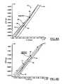
- FIG. 4Ais a graph illustrating exit ramp locations relative to road survey edges for a single lane transitioning into an exit ramp, which is branching from the single lane according to the present invention.
- FIG. 4Bis a graph illustrating ramp locations relative to road survey edges for two lanes transitioning into two high speed connector ramps 76 according to the present invention.
- FIG. 5Ais a placement diagrammatic view of a navigation induced placement error of a vehicle using a control system operating on an exit only lane in accordance with an embodiment of the present invention.
- FIG. 5Bis a placement diagrammatic view of navigation induced placement error of a vehicle using a control system operating on an exit ramp and predicting the vehicle to be on a previously exited highway in accordance with an embodiment of the present invention.
- FIG. 5Cis a placement diagrammatic view of navigation induced placement error of a vehicle using a control system operating on a highway and predicting the vehicle to be on a close parallel road in accordance with an embodiment of the present invention.
- FIG. 6is a flowchart illustrating a ramp-based approach for resume mode algorithm in accordance with an embodiment of the present invention.
- FIG. 7is a stateflow diagram illustrating control logic for ramp based InhibitResume mode in accordance with an embodiment of the present invention.
- FIG. 8is a stateflow diagram illustrating control logic for inhibit resume as implemented in the ACC follow mode control according to an embodiment of the present invention.
- FIG. 9is a stateflow diagram illustrating control logic for a candidate method of ramp detection in accordance with an embodiment of the present invention.
- FIG. 10is a vehicle position overlay on a map illustrating a navigation system exit ramp prediction, using the candidate method, for a vehicle on a road approaching an exit ramp according to an embodiment of the present invention.
- FIG. 11Ais a vehicle position overlay on a map illustrating an incorrect navigation system vehicle prediction location event for a vehicle near an exit ramp according to an embodiment of the present invention.
- FIG. 11Bis a vehicle position overlay on a map illustrating a next time sequence from the event in FIG. 12A of a correct navigation system vehicle prediction location according to an embodiment of the present invention.
- FIG. 12is a vehicle position overlay on a map illustrating navigation system misplaced position data for a vehicle, on a highway that is parallel to a side road according to an embodiment of the present invention.
- FIG. 13is a vehicle position overlay on a map illustrating a navigation system exit ramp prediction, using a successor method, for a vehicle on a road approaching an exit ramp according to an embodiment of the present invention.
- FIG. 14is a vehicle position overlay on a map illustrating a navigation system exit ramp prediction, using both the candidate and successor methods, for a vehicle on a road near an exit ramp according to an embodiment of the present invention.
- adaptive speed control apparatus and methodis capable of being adapted for various purposes and is not limited to the following applications: cruise control systems, forward collision warning systems, collision avoidance systems, vehicle systems, or other systems that may require adaptive speed control.
- FIGS. 1A and 1Bplacement diagrammatic views of an automotive vehicle 10 using an ACC system initially following a target vehicle 12 and approaching a ramp 16 followed by no longer following the target vehicle 12 and entering the ramp, are shown.
- a vehicle 10is using an ACC system following a target vehicle 12 on road 14 and approaching a ramp 16 .
- FIG. 1Bafter vehicle 10 has been following a target vehicle 12 , it proceeds onto the ramp 16 .
- a rampis a road segment that allows a vehicle to enter or exit another road.
- a rampmay include but is not limited to an: exit ramp, off ramp, on ramp, high-speed connector ramp, or any other road segment that provides a method of allowing a vehicle to enter or exit another road.
- a typical ACC systemwould initiate an automatic resume and accelerate the vehicle 10 to the set speed. This is in contrast to the control system 20 of the present invention which detects the ramp 16 and initiates an inhibit resume mode to prevent the vehicle 10 from accelerating.
- An assumption for the situation above describedis that the set speed is greater than current follow of the vehicle 10 .
- FIG. 2a block diagrammatic view of a control system 20 located in a vehicle 22 according to an embodiment of the present invention is shown.
- the system 20includes a vehicle controller 24 that is preferably microprocessor-based. Controller 24 is illustrating having a memory 26 therein for storing information related to vehicle position, target vehicle position, and vehicle characteristics. However, memory 26 may also be a separate component. The controller 24 receives signals from several sensors and systems located within the vehicle 22 .
- the controller 24receives a detected target vehicle signal from a detection system 28 .
- the detection system 28 of the present inventionis radar based the detection system 28 may be laser based, infrared based, x-ray based, or based off other detection methods known in the art.
- the target vehicle signalconsists of a target vehicle location relative to the vehicle 22 and a road on which the vehicle 22 is being operated.
- the target vehicle signalalso consists of a distance value between the target vehicle and the vehicle 22 and the speed of the target vehicle relative to the speed of the vehicle 22 .
- the controller 24measures the yaw rate of the vehicle 22 using a yaw rate sensor 30 , which generates a yaw rate signal corresponding to the yawing of the vehicle about an axis extending vertically at the center of gravity of the vehicle.
- the yaw rate signalscaled with vehicle speed, is an indication of the instantaneous curvature of a road the vehicle 22 is traveling.
- the yaw rate sensormay be used in determining whether the vehicle 22 has entered a ramp and what type of ramp the vehicle 22 is on, as will be further described below.
- the controller 24also measures the velocity of the vehicle 24 using a speed sensor 32 .
- a speed sensor 32is illustrated as a single sensor, various numbers of sensors may be employed.
- a suitable speed sensoremploys four sensors located at a respective wheel.
- the speed of the vehiclemay be obtained therefrom in a known way similar to that of an anti-lock braking system.
- the speed sensormay be used by the system 20 not only in adjusting the speed of the vehicle but also in road classification verification.
- the controller 24receives a navigation signal from a navigation system 34 .
- the navigation system 34includes a vehicle positioning module 36 which uses a Global Positioning System 38 and a digital map database 40 to predict a vehicle position and location.
- the navigation system 34may perform a map query, thereby, classifying road segments.
- the navigation signalmay also include but is not limited to data on information including: vehicle position, ramp location, speed category, future vehicle path, number of lanes, road type, road inclination, road conditions or other data that may effect whether to adjust the speed of the vehicle 22 .
- the controller 24 in a preferred embodiment of the present inventionalso receives a lane change signal from a radar based lane change detector 46 .
- the lane change detector 46informs the controller 24 of when the vehicle 22 has changed lanes.
- the lane change signalis used in determining whether the vehicle has entered an exit ramp.
- the lane change detector 46may be of various style.
- the lane change detector 46may include the global positioning system 38 , radar sensors, infrared sensors, ultrasonic sensors, laser sensors, cameras, or other lane change detection sensors or vision based components.
- Lane change detector 46may simply detect a lane change or may track the manner as to which a lane is changed.
- a computer vision based lane change trackermay monitor lane changes to determine positioning of vehicles on a road or whether a vehicle is departing from a road.
- the lane change detector 46may also use various techniques to detect or track a lane change, such as tracking a color, shape, pattern, of a lane marker.
- Lane change detector 46may also monitor whether a lane marker is solid or segmented.
- Lane change detector 46may also detect metallic, magnetic, or other lane marker and object material or signals in determining a lane change.
- the lane change detectormay monitor objects other than the host vehicle to determine that the host vehicle or target vehicle has changed a
- the controller 24may also use a warning system 48 to alert the operator of impeding objects in response to the object profile, the yaw rate, the speed at the vehicle, the navigation signal, and the operating mode.
- the controller 24in response to the target vehicle signal, the yaw rate signal, the speed of the vehicle 22 , the navigation signal, and the lane change signal, determines the system 20 operating mode.
- Some of the system 20 operating modesare as follows: follow mode, cruise mode, auto resume mode, or inhibit resume mode.
- follow modeis when the system 20 is continuously adjusting the speed of the vehicle 22 to remain a headway distance from a target vehicle in the future path of the vehicle 22 .
- cruise modethe system 20 is continuously adjusting the speed of the vehicle 22 to remain at a set speed.
- auto resume modethe system 20 is slowly accelerating the vehicle 22 to a set speed.
- inhibit resume modethe system 20 is not accelerating the vehicle 22 .
- the system 20 using the vehicle accelerator 42 or brakes 44adjusts the speed of the vehicle 22 accordingly.
- the system 20may use the vehicle accelerator 42 or may use mechanical or electrical throttle control device in adjusting the speed of the vehicle 22 .
- FIG. 3a macro-view of a freeway interchange 50 having known coordinate locations represented by various markers 52 according to the present invention is shown.
- Production navigation systemsuse GPS (global positioning systems), dead reckoning, map matching, and a digital map database to locate a vehicle on a map, and route the vehicle to a destination given a set of routing criteria.
- Road classificationin terms of average travel speed are attached to each road segment 54 , which have a start node identification. Road segments are further classified with information pertaining to permissible travel directions such as a one-way street or a divided highway.
- Ramp signs and ramp classification attributesare attached to ramp sections 56 .
- an exit rampmay have a ramp class link of 19587642. The class link refers to the location and classification of a road segment.
- the road classificationpermits straightforward extraction of ramp status from the map database 40 , issues with map database 40 inaccuracy and the ability of the navigation system 34 to place the vehicle 22 on the correct road section add uncertainty to ramp detection.
- FIG. 4Aa graph illustrating exit ramp locations 60 relative to road survey edges 62 for a single lane 64 transitioning into an exit ramp 66 branching from the single lane 64 according to the present invention.
- the navigation system 34searches road segment information for start node identification.
- the navigation system 34also searches road segment information for highway and ramp segment pairs that have identical start nodes.
- An exit rampis identified in response to an identical start node.
- Link 19587642is a ramp class link that branches off the single lane 64 , at a location represented by triangle 68 that is part of freeway 70 .
- the map database pathis represented by the dashed lines 72 . The distance between the map database transition and the actual coordinates of where the exit ramp branches off a freeway varies per exit ramp causing varying inaccuracy in vehicle placement.
- FIGS. 3 and 4Ba graph illustrating ramp locations 73 relative to road survey edges 62 for two lanes 74 transitioning into two high-speed connector ramps 76 according to the present invention is shown.
- the ramp class link 19587642transitions to class links 19587844 and class link 19587818.
- the link transitionoccurs close to the actual ramp split 78 and is represented by triangle 80 .
- FIG. 5Aa placement diagrammatic view of a navigation induced placement error of a vehicle using an ACC system operating on an exit only lane in accordance with an embodiment of the present invention is shown.
- the lateral placement errorsmay arise in three situations. First lateral placement error may arise when the navigation system 34 experiences an “exit only” lane 90 the system 34 does not classify the lane 90 as an exit ramp 102 . Therefore, the navigation system 34 begins to operate in cruise resume mode when no target vehicle is detected and accelerates the vehicle 22 , while operating in the exit only lane and being directed towards the exit ramp 102 , towards the exit ramp 102 and enter the ramp 102 at a higher speed.
- FIG. 5Ba placement diagrammatic view of navigation induced placement error of a vehicle using an ACC system operating on an exit ramp and predicting the vehicle to be on a previously exited highway in accordance with an embodiment of the present invention is shown.
- Another lateral placement erroroccurs when the exit ramp 102 gradually branches off from the highway 100 , thereby, the navigation system 34 remains predicting the vehicle 22 to be on the highway 100 instead of on the exit ramp 102 represented by triangle 104 . Also, inhibit resume mode is not enabled.
- FIG. 5Cis a placement diagrammatic view of navigation induced placement error of a vehicle using an ACC system operating on a highway and predicting the vehicle to be on a close parallel road in accordance with an embodiment of the present invention is shown.
- a lateral placement erroroccurs when a parallel road, for example a service drive 106 is near the highway 100 and the navigation system 34 predicts the vehicle 22 to be on the service drive 106 instead of the highway 100 , as best shown in FIG. 5C .
- the final situationmay cause the navigation system 34 to not identify an exit ramp for miles.
- FIG. 6a flowchart illustrating a ramp-based approach for a resume mode algorithm in accordance with an embodiment of the present invention is shown.
- steps 120 and 122a current road segment and a proceeding road segment speed are classified by the navigation system 34 .
- the system 20then proceeds to step 124 .
- step 124when the current segment is a ramp and the speed classification is high the vehicle is on a high-speed connector ramp.
- the system 20proceeds to step 126 .
- step 126When the road segment is a ramp and the speed classification is low, the vehicle is on an exit ramp.
- the system 20then proceeds to step 125 in which an inhibit resume mode is entered.
- step 125the system 20 is in inhibit resume mode.
- an exit rampis detected the system 20 inhibits the resume speed of the vehicle 22 until the vehicle is operating on a road segment that corresponds to the set speed.
- step 124ramp status is set to one for a high-speed connector ramp.
- step 126is performed.
- step 128is performed.
- the system 20proceeds to operate in resume mode. Otherwise when a ramp is detected and the ramp status value is zero or some other criteria is met step 125 is performed.
- FIG. 7a stateflow diagram illustrating control logic for ramp based inhibit resume mode in accordance with an embodiment of the present invention is shown.
- the system 20has two main states, during inhibit resume mode, inhibit on state 150 and inhibit off state 152 .
- inhibit off state 152the system 20 disables inhibit resume based on an operator selection or when the navigation system 34 is not providing reliable positioning. Otherwise inhibit on state 150 is performed.
- the system 20waits for a ramp flag to be set equal to one in which a inhibit on state 150 is performed or, a logic “OR” gate is represented by circle 154 , the ramp flag is set to zero in which a inhibit wait state 156 is performed.
- the system 20waits until a ramp is detected and the ramp flag is set equal to one.
- the inhibit state 158is performed.
- the system 20starts an inhibit resume state 160 when a timer is equal to zero, otherwise a warning state 162 is performed.
- state 160the system continues to inhibit resume speed of the vehicle 22 .
- the warning state 162is performed when the timer value is greater than a predetermined value and navigation system 34 decides to warn the operator.
- the system 20is operating in a warning state 164 or a warning silent state 166 .
- the systemwarns the operator that inhibit resume is active after a predetermined time delay.
- the controller 24may use the warning system 48 to alert the operator.
- the warning system 48allows the operator to have ample time to react when necessary.
- a warning silent state 166is performed after the warning signal to the operator has occurred for a time period greater then a preset time duration.
- the systemceases to warn the operator and returns back to the state 160 .
- FIG. 8a stateflow diagram illustrating control logic for inhibit resume as implemented in the ACC follow mode control according to an embodiment of the present invention is shown.
- initialization state 170the system 20 is powered on, initialized, and the set speed is set manually by the operator.
- the system 20is waiting for a ramp flag and continuously monitoring for a target vehicle.
- ACC active state 172the system 20 operates in either a follow control state 174 or cruise control state 176 .
- the vehicle 22is following a target vehicle and adjusting the vehicle speed to remain a predetermined distance from the target vehicle as known in the art.
- the follow control state 174is overridden by either the detection of a target vehicle, the detection of an exit ramp, or manually overridden by the operator.
- the system 20In the cruise control state 176 the system 20 is operating the vehicle 22 at the set speed until a target vehicle is detected, an exit ramp is detected, or other vehicle characteristic overrides the cruise control state 176 . In the cruise control state 176 , the system 20 is further operating in a feedback control state 180 or a cruise override state 182 .
- the system 20is operating in either a Cruising state 184 or an inhibit resume state 186 .
- the vehicle 22In the cruising state 188 , the vehicle 22 is cruising at the set speed shown by box 188 or adjusting the vehicle speed accordingly to maintain the set speed shown by box 190 .
- inhibit resume state 186when an exit ramp is detected the system 20 inhibits the resume speed of the vehicle 22 until the vehicle is operating on a road segment that corresponds to the set speed. During inhibit resume, vehicle speed is held constant.
- the feedback control state 180may be overridden by manual control, shown by box 183 .
- the operatormay manually adjust the speed of the vehicle 22 , cancel the set speed, or may power off the system 20 altogether.
- the present inventionuses not only a navigation system 34 but also a radar based lane change detector 46 for vehicle position prediction.
- the lane change detector 46provides a flag to the ACC control logic that indicates when the vehicle 22 has moved laterally left or right a distance commensurate of approximately half a lane change.
- the lane change detector 46may have tracking errors that may lead to false lane change indications.
- the false lane change indicationsare not a major problem since the near ramp and ramp direction conditions must match before the system 20 inhibits resume speed of the vehicle 22 , therefore minimizing the number of false indications.
- the navigation system 34provides information that a ramp is nearby. Ramp proximity is an indirect result of the map matching process that determines the most probable vehicle position.
- the system 20uses input information such as vehicle speed, yaw rate, GPS data, and map data in conjunction with algorithms within the vehicle position module to determine up to fifteen possible vehicle positions (candidates) on a digital map.
- map matchingforms a list of probable candidate positions. A “swarm” of positions are created around the most probable position. Each candidate is assigned a probability. The candidate with the highest probability is the “best” candidate. The “best” candidate represents the predicted vehicle position. When a candidate, in the swarm of candidates, is on an exit ramp, a ramp can be flagged as being nearby, but as discussed above the system 20 would trigger inhibit resume.
- FIG. 9a stateflow diagram illustrating control logic for a candidate method of ramp detection in accordance with an embodiment of the present invention is shown.
- near ramp detector state 200the system 20 is monitoring the navigation signal and the lane change detector 46 to determine whether the vehicle 22 is near an exit ramp.
- a near ramp wait state 202is performed.
- the system 20sets a near ramp flag equal to one when the vehicle 22 is near an exit ramp or near ramp flag equal to zero when the vehicle 22 is no longer near an exit ramp.
- ramp near state 204is performed.
- the system 20determines whether the exit ramp is upcoming on the left side of the vehicle 22 or the right side of the vehicle 22 .
- a ramp left flagis set equal to one.
- a ramp right flagis set equal to one.
- the near ramp flagis equal to one the system 20 then proceeds to the ramp probable state 206 otherwise the system 20 returns to the near ramp wait state 202 .
- an iterative processcontinues until the vehicle 22 is no longer near the exit ramp and the duration of the time the vehicle 22 was near the exit ramp is greater than a predetermined ramp hold time.
- the NearRamp flagremains equal to one.
- Ramp direction informationis combined with the lane change detector information to determine whether a left or right lane change has occurred in order to infer that an exit ramp has been taken.
- the near ramp flagis set equal to zero.
- a ramp timerbegins counting time until the counted time is greater than the predetermined hold time at which the system 20 returns to the near ramp wait state 202 .
- Each road segment in the map databasehas a heading component, whereby the system 20 using the data calculates the direction of the exit ramp with respect to the highway. Thus it is possible to determine whether the ramp exits to the left or to the right.
- FIG. 10a vehicle position overlay on a map illustrating a navigation system exit ramp prediction, using the candidate method, for a vehicle on a road approaching an exit ramp according to an embodiment of the present invention is shown.
- the triangle symbols 220represent each candidate's position and point in the direction of travel of the vehicle 22 .
- Triangle 222 with a dark borderrepresents the best probable candidate.
- the candidatesare lined up along the highway segment 224 with the best candidate 222 located near the center of the swarm 226 .
- Other candidate swarm patternsare created for different road segments. The larger the triangle the higher the probability value.
- a candidate 228is on an exit ramp 230 , in which the system 20 determines the vehicle 22 is near the exit ramp 230 .
- FIGS. 11A and 11Billustrating a potential problem of when vehicle 22 is operating on an exit ramp, represented by triangle 232 , and yet the navigation system 34 continues to predict the vehicle position to be on the highway 240 , represented by triangle 234 (similar to the problem illustrated in FIG. 5B ).
- the problemis overcome by using the candidate prediction method, in which the navigation system 34 is able to detect that there is an exit ramp 242 nearby and whether the exit ramp 242 is on the left side or the right side of the vehicle 22 .
- the systemcorrects this problem by assuming the vehicle 22 is on the exit ramp 242 , represented by triangle 244 and the system inhibit resume speed of the vehicle 22 .
- FIG. 12a vehicle position overlay on a map illustrating another potential problem with using a navigation prediction system alone and misplacing the vehicle position on a highway 250 that is parallel to a side road, such as a service drive or frontage road, according to an embodiment of the present invention is shown (similar to the problem illustrated in FIG. 5C ).
- the triangles 254represent incorrect “best” candidate predicted vehicle positions showing the vehicle to be on a side road.
- the triangles 256represent other correct candidate positions. This problem is solved by also looking at both the candidate positions and the lane change detection signal.
- the system 20may assume the vehicle 22 is on the exit ramp 258 .
- the candidate methodmay also be used when the ramp has minimal curvature or small ramp departure angle with respect to the highway.
- a vehicle position overlay 259 on a map 260 illustrating a navigation system exit ramp prediction, using a successor method, for a vehicle 22 on a road 261 approaching an exit ramp 262 according to an embodiment of the present inventionis shown.
- the successor methodprovides added benefits to the candidate method.
- the successor methodincreases the “preview distance” of the navigation system 34 so as to monitor for exit ramps earlier.
- the successor methodprovides for early detection when there is an exit only lane just before an exit ramp 262 (similar to the problem illustrated in FIG. 5A ). Without the successor method the vehicle may remain in cruise mode or resume mode while in the exit only lane.
- the successor methodprovides for inhibit resume while the vehicle 22 is in an exit only lane.
- a vehicle position overlay 270 on a map 272 illustrating a navigation system exit ramp prediction, using both the candidate and successor methods, for a vehicle 22 on a road 261 near an exit ramp 262 according to an embodiment of the present inventionis shown.
- the candidate methoddetects the exit ramp 274 on the left and the successor method detects the next exit ramp 262 on the right.
- the navigation system 34positions the vehicle 22 on the left exit ramp 274 , on the highway 261 , or on the right exit ramp 262 .
- the yaw rate sensor 30may be used in combination with the above mentioned methods to detect road curvature and further increase the prediction accuracy for exit ramps.
- Implementation of inhibit resume during exit ramp detectionprovides an additional safety enhancement to traditional cruise control systems.
- the present inventionintroduces exit ramps and situational awareness information into a control system in a useful manner that enhances operator comfort and safety without detracting from current performance standards.
Landscapes
- Engineering & Computer Science (AREA)
- Transportation (AREA)
- Mechanical Engineering (AREA)
- Chemical & Material Sciences (AREA)
- Combustion & Propulsion (AREA)
- Automation & Control Theory (AREA)
- Control Of Driving Devices And Active Controlling Of Vehicle (AREA)
- Traffic Control Systems (AREA)
Abstract
Description
Claims (8)
Priority Applications (1)
| Application Number | Priority Date | Filing Date | Title |
|---|---|---|---|
| US10/063,501US7260465B2 (en) | 2002-04-30 | 2002-04-30 | Ramp identification in adaptive cruise control |
Applications Claiming Priority (1)
| Application Number | Priority Date | Filing Date | Title |
|---|---|---|---|
| US10/063,501US7260465B2 (en) | 2002-04-30 | 2002-04-30 | Ramp identification in adaptive cruise control |
Publications (2)
| Publication Number | Publication Date |
|---|---|
| US20030204299A1 US20030204299A1 (en) | 2003-10-30 |
| US7260465B2true US7260465B2 (en) | 2007-08-21 |
Family
ID=29248099
Family Applications (1)
| Application Number | Title | Priority Date | Filing Date |
|---|---|---|---|
| US10/063,501Expired - LifetimeUS7260465B2 (en) | 2002-04-30 | 2002-04-30 | Ramp identification in adaptive cruise control |
Country Status (1)
| Country | Link |
|---|---|
| US (1) | US7260465B2 (en) |
Cited By (36)
| Publication number | Priority date | Publication date | Assignee | Title |
|---|---|---|---|---|
| US20060229792A1 (en)* | 2005-03-31 | 2006-10-12 | Nissan Technical Center North America, Inc. | System and methods utilizing slope of target speed for cooperative speed for cooperative speed control system |
| US20070233386A1 (en)* | 2006-03-29 | 2007-10-04 | Fuji Jukogyo Kabushiki Kaisha | Traffic lane deviation preventing system for a vehicle |
| US20080300783A1 (en)* | 2007-05-31 | 2008-12-04 | Aisin Aw Co., Ltd. | Navigation devices, methods, and programs |
| US20090276135A1 (en)* | 2005-06-07 | 2009-11-05 | Markus Hagemann | Adaptive cruise controller having dynamics matching as a function of the situation |
| US8014928B2 (en) | 2008-06-17 | 2011-09-06 | Ford Global Technologies, Llc | Automotive slipstreaming support system |
| US20110251749A1 (en)* | 2010-04-09 | 2011-10-13 | Chris Schwarz | Method and system for vehicle ESC system using map data |
| US20110251748A1 (en)* | 2010-04-09 | 2011-10-13 | Navteq North America, Llc | Method and system for vehicle ESC system using map data |
| WO2012129437A3 (en)* | 2011-03-23 | 2012-11-29 | Tk Holdings Inc. | Driver assistance system |
| WO2012129425A3 (en)* | 2011-03-23 | 2013-02-28 | Tk Holdings Inc. | Driver assistance system |
| US8744675B2 (en) | 2012-02-29 | 2014-06-03 | Ford Global Technologies | Advanced driver assistance system feature performance using off-vehicle communications |
| US20140354454A1 (en)* | 2011-09-13 | 2014-12-04 | Stefan Nordbruch | detecting travel of a vehicle in an impermissible driving direction |
| US8996197B2 (en) | 2013-06-20 | 2015-03-31 | Ford Global Technologies, Llc | Lane monitoring with electronic horizon |
| US9150220B2 (en) | 2013-12-04 | 2015-10-06 | Mobileye Vision Technologies Ltd. | Systems and methods for mimicking a leading vehicle |
| CN105346390A (en)* | 2015-10-21 | 2016-02-24 | 奇瑞汽车股份有限公司 | Constant-speed cruise control system and method based on vehicle-mounted navigation system |
| WO2016173717A1 (en) | 2015-04-29 | 2016-11-03 | Knorr-Bremse Systeme für Nutzfahrzeuge GmbH | Method and device for regulating the speed of a vehicle |
| US9738280B2 (en) | 2013-10-03 | 2017-08-22 | Robert Bosch Gmbh | Adaptive cruise control with on-ramp detection |
| WO2017205278A1 (en)* | 2016-05-23 | 2017-11-30 | nuTonomy Inc. | Supervisory control of vehicles |
| US10037696B2 (en)* | 2016-03-31 | 2018-07-31 | Delphi Technologies, Inc. | Cooperative automated vehicle system |
| US10126136B2 (en) | 2016-06-14 | 2018-11-13 | nuTonomy Inc. | Route planning for an autonomous vehicle |
| US20190061755A1 (en)* | 2017-08-29 | 2019-02-28 | Ford Global Technologies, Llc | Inhibiting highway assist mode |
| CN109559532A (en)* | 2018-12-10 | 2019-04-02 | 北京工业大学 | Expressway exit shunting zone bus or train route Cooperative Security pre-warning and control method |
| US10309792B2 (en) | 2016-06-14 | 2019-06-04 | nuTonomy Inc. | Route planning for an autonomous vehicle |
| US10331129B2 (en) | 2016-10-20 | 2019-06-25 | nuTonomy Inc. | Identifying a stopping place for an autonomous vehicle |
| DE102018201896A1 (en) | 2018-02-07 | 2019-08-08 | Ford Global Technologies, Llc | Determining the driving of a vehicle on a driveway |
| US10473470B2 (en) | 2016-10-20 | 2019-11-12 | nuTonomy Inc. | Identifying a stopping place for an autonomous vehicle |
| US10681513B2 (en) | 2016-10-20 | 2020-06-09 | nuTonomy Inc. | Identifying a stopping place for an autonomous vehicle |
| US20200191603A1 (en)* | 2018-12-12 | 2020-06-18 | Here Global B.V. | Methods and systems for roadwork extension identification using speed funnels |
| US10829116B2 (en) | 2016-07-01 | 2020-11-10 | nuTonomy Inc. | Affecting functions of a vehicle based on function-related information about its environment |
| US10857994B2 (en) | 2016-10-20 | 2020-12-08 | Motional Ad Llc | Identifying a stopping place for an autonomous vehicle |
| US11092446B2 (en) | 2016-06-14 | 2021-08-17 | Motional Ad Llc | Route planning for an autonomous vehicle |
| US11097735B1 (en) | 2020-03-19 | 2021-08-24 | Toyota Motor North America, Inc. | Transport lane usage |
| US20220306103A1 (en)* | 2021-03-25 | 2022-09-29 | Toyota Jidosha Kabushiki Kaisha | Automatic speed control device, automatic speed control method, and automatic speed control program |
| US11488424B2 (en) | 2020-03-19 | 2022-11-01 | Toyota Motor North America, Inc. | Motion-based transport assessment |
| US11720114B2 (en) | 2020-03-19 | 2023-08-08 | Toyota Motor North America, Inc. | Safety of transport maneuvering |
| DE102023116978A1 (en) | 2023-06-28 | 2025-01-02 | Valeo Schalter Und Sensoren Gmbh | Method for operating an adaptive cruise control system in a motor vehicle |
| US12208800B2 (en) | 2022-06-06 | 2025-01-28 | Ford Global Techologies, Llc | Methods and apparatuses for dynamic vehicle access permissioning analysis and handling |
Families Citing this family (37)
| Publication number | Priority date | Publication date | Assignee | Title |
|---|---|---|---|---|
| DE10356860A1 (en)* | 2003-12-05 | 2005-07-07 | Siemens Ag | Method and system for reliability-dependent activation-deactivation of functions |
| DE10360129A1 (en)* | 2003-12-20 | 2005-07-21 | Daimlerchrysler Ag | Driving assistance device, vehicle and method for driving speed control of a vehicle |
| JP2005186813A (en)* | 2003-12-25 | 2005-07-14 | Fuji Heavy Ind Ltd | Vehicle driving support device |
| DE102004019337A1 (en)* | 2004-04-21 | 2005-11-17 | Siemens Ag | Assistance system for motor vehicles |
| DE102005014309A1 (en)* | 2005-03-30 | 2006-10-05 | Robert Bosch Gmbh | Speed and distance control device for motor vehicles |
| US7545956B2 (en)* | 2005-08-12 | 2009-06-09 | Visteon Global Technologies, Inc. | Single camera system and method for range and lateral position measurement of a preceding vehicle |
| US7266438B2 (en)* | 2005-08-26 | 2007-09-04 | Gm Global Technology Operations, Inc. | Method of assisting driver to negotiate a roadway |
| JP4720383B2 (en) | 2005-09-01 | 2011-07-13 | トヨタ自動車株式会社 | Vehicle control device |
| US20080065328A1 (en)* | 2006-09-08 | 2008-03-13 | Andreas Eidehall | Method and system for collision avoidance |
| JP5244787B2 (en)* | 2007-03-29 | 2013-07-24 | トヨタ自動車株式会社 | Collision possibility acquisition device and collision possibility acquisition method |
| JP4933962B2 (en)* | 2007-06-22 | 2012-05-16 | 富士重工業株式会社 | Branch entry judgment device |
| JP4450023B2 (en)* | 2007-07-12 | 2010-04-14 | トヨタ自動車株式会社 | Own vehicle risk acquisition device |
| JP5061776B2 (en)* | 2007-08-03 | 2012-10-31 | 日産自動車株式会社 | Vehicle travel control device and vehicle travel control method |
| JP4748232B2 (en)* | 2009-02-27 | 2011-08-17 | トヨタ自動車株式会社 | Driving assistance device |
| US8417448B1 (en) | 2010-04-14 | 2013-04-09 | Jason Adam Denise | Electronic direction technology |
| US8818678B2 (en)* | 2010-08-24 | 2014-08-26 | GM Global Technology Operations LLC | Method for preventing activation of resume function in a cruise control system |
| KR101472615B1 (en)* | 2010-12-21 | 2014-12-16 | 삼성전기주식회사 | System and method for warning lane departure |
| EP2711909B1 (en)* | 2011-05-20 | 2018-07-18 | Honda Motor Co., Ltd. | Lane change assistant information visualization system |
| FR2977851B1 (en)* | 2011-07-13 | 2014-02-14 | Renault Sa | SPEED CONTROL CONTROL FOR A VEHICLE |
| US8996273B2 (en) | 2012-08-31 | 2015-03-31 | GM Global Technology Operations LLC | Anticipatory cruise control |
| US10002433B2 (en)* | 2012-12-26 | 2018-06-19 | Nippon Soken, Inc. | Boundary line recognition apparatus and branch road determination apparatus |
| KR101558786B1 (en)* | 2014-06-30 | 2015-10-07 | 현대자동차주식회사 | Apparatus and method for recognizing driving lane of vehicle |
| FR3025475B1 (en)* | 2014-09-04 | 2016-12-30 | Renault Sa | "METHOD OF AUTOMATICALLY DEACTIVATING A SPEED REGULATOR THROUGH VERIFICATION OF VISUAL CRITERIA" |
| JP6423212B2 (en)* | 2014-09-12 | 2018-11-14 | 株式会社ゼンリン | Driving support system, data structure |
| JP6138840B2 (en)* | 2015-02-27 | 2017-05-31 | 株式会社Subaru | Vehicle control apparatus and vehicle control method |
| US9650043B2 (en) | 2015-04-30 | 2017-05-16 | GM Global Technology Operations LLC | Real-time anticipatory speed control |
| JP6390525B2 (en)* | 2015-06-04 | 2018-09-19 | 株式会社デンソー | Driving assistance device |
| US10131362B1 (en)* | 2015-06-23 | 2018-11-20 | United Services Automobile Association (Usaa) | Automobile detection system |
| JP6475130B2 (en)* | 2015-09-17 | 2019-02-27 | トヨタ自動車株式会社 | Vehicle speed control device |
| CN109690344B (en)* | 2016-06-17 | 2023-06-27 | 罗伯特·博世有限公司 | Overtaking acceleration assist for adaptive cruise control in vehicles |
| CN111886167A (en)* | 2017-12-27 | 2020-11-03 | 宝马股份公司 | Autonomous vehicle control via collision risk map |
| US11167759B2 (en)* | 2019-04-10 | 2021-11-09 | GM Global Technology Operations LLC | Method and apparatus for controlling a vehicle including an adaptive cruise control system |
| JP7414683B2 (en)* | 2020-09-29 | 2024-01-16 | 日立Astemo株式会社 | Own vehicle position estimation device and own vehicle position estimation method |
| CN112896162B (en)* | 2021-03-29 | 2022-09-27 | 东风汽车集团股份有限公司 | Method and device for optimally controlling longitudinal running of automobile under ramp working condition |
| DE102021206694A1 (en) | 2021-06-28 | 2022-12-29 | Volkswagen Aktiengesellschaft | Method for carrying out a lane change on a deceleration lane using an assistance system, computer program product and assistance system |
| CN114200825B (en)* | 2021-10-29 | 2024-01-19 | 东风商用车有限公司 | Whole car self-adaptation control system |
| US20230415741A1 (en)* | 2022-06-22 | 2023-12-28 | Aptiv Technologies Limited | Target of Interest Selection on Roadway Ramps |
Citations (24)
| Publication number | Priority date | Publication date | Assignee | Title |
|---|---|---|---|---|
| US4670845A (en) | 1983-12-06 | 1987-06-02 | Nissan Motor Company, Limited | System and method for automatically controlling vehicle speed |
| US5485161A (en) | 1994-11-21 | 1996-01-16 | Trimble Navigation Limited | Vehicle speed control based on GPS/MAP matching of posted speeds |
| US5745870A (en) | 1994-09-14 | 1998-04-28 | Mazda Motor Corporation | Traveling-path prediction apparatus and method for vehicles |
| US5771007A (en) | 1995-11-24 | 1998-06-23 | Honda Giken Kogyo Kabushiki Kaisha | Auto-cruise system for vehicle |
| JPH10329576A (en)* | 1997-06-04 | 1998-12-15 | Toyota Motor Corp | Vehicle travel control device |
| US5854987A (en)* | 1995-02-22 | 1998-12-29 | Honda Giken Kogyo Kabushiki Kaisha | Vehicle steering control system using navigation system |
| US5902345A (en) | 1995-05-25 | 1999-05-11 | Hitachi, Ltd. | Method and apparatus for controller power train of motor vehicle |
| US5977869A (en) | 1996-12-04 | 1999-11-02 | Volkswagen Ag | Motor vehicle speed control method and arrangement |
| US6085137A (en)* | 1996-10-25 | 2000-07-04 | Kabushikikaisha Equos Research | Vehicle control device |
| US6125324A (en)* | 1997-04-09 | 2000-09-26 | Honda Giken Kogyo Kabushiki Kaisha | Vehicle control apparatus |
| US6141619A (en)* | 1996-11-07 | 2000-10-31 | Honda Giken Kogyo Kabushiki Kaisha | Vehicle control system |
| US6161072A (en)* | 1999-01-21 | 2000-12-12 | Intel Corporation | Automatic cruise control |
| US6320515B1 (en)* | 1996-08-09 | 2001-11-20 | Kjell Olsson | Method and equipment for motorway control |
| US20010056326A1 (en)* | 2000-04-11 | 2001-12-27 | Keiichi Kimura | Navigation apparatus, method for map matching performed in the navigation apparatus, and computer-readable medium storing a program for executing the method |
| US6343253B1 (en)* | 1999-09-21 | 2002-01-29 | Fuji Jukogyo Kabushiki Kaisha | Road shape estimation apparatus and curve approach control apparatus |
| US20020031242A1 (en)* | 1996-08-28 | 2002-03-14 | Nobuhiko Yasui | Local positioning appartus, and method therefor |
| US20020042672A1 (en)* | 2000-10-11 | 2002-04-11 | Toyota Jidosha Kabushiki Kaisha | Vehicular shift control unit and vehicular automatic shift control method |
| US20020080617A1 (en)* | 2000-12-27 | 2002-06-27 | Aisin Aw Co., Ltd | Light distribution control apparatus |
| US6418367B1 (en)* | 1999-10-08 | 2002-07-09 | Nissan Motor Co., Ltd. | Engine transmission control system |
| US20020095246A1 (en)* | 2001-01-18 | 2002-07-18 | Nissan Motor Co., Ltd. | Lane tracking control system for vehicle |
| US6473685B2 (en)* | 1997-12-01 | 2002-10-29 | Hitachi, Ltd. | Vehicle speed control apparatus |
| US20020173903A1 (en)* | 2001-05-21 | 2002-11-21 | Phung Tam A. | Environmental traffic recognition identification prediction strategies |
| US20030023369A1 (en)* | 2000-08-23 | 2003-01-30 | Koji Takashima | Vehicle-mounted position computing apparatus |
| US20030135318A1 (en)* | 2002-01-17 | 2003-07-17 | Levasseur Tellis | Stop and go adaptive cruise control system |
- 2002
- 2002-04-30USUS10/063,501patent/US7260465B2/ennot_activeExpired - Lifetime
Patent Citations (25)
| Publication number | Priority date | Publication date | Assignee | Title |
|---|---|---|---|---|
| US4670845A (en) | 1983-12-06 | 1987-06-02 | Nissan Motor Company, Limited | System and method for automatically controlling vehicle speed |
| US5745870A (en) | 1994-09-14 | 1998-04-28 | Mazda Motor Corporation | Traveling-path prediction apparatus and method for vehicles |
| US5485161A (en) | 1994-11-21 | 1996-01-16 | Trimble Navigation Limited | Vehicle speed control based on GPS/MAP matching of posted speeds |
| US5928299A (en)* | 1995-02-22 | 1999-07-27 | Honda Giken Kogyo Kabushiki Kaisha | Vehicle control system using navigation system steering |
| US5854987A (en)* | 1995-02-22 | 1998-12-29 | Honda Giken Kogyo Kabushiki Kaisha | Vehicle steering control system using navigation system |
| US5902345A (en) | 1995-05-25 | 1999-05-11 | Hitachi, Ltd. | Method and apparatus for controller power train of motor vehicle |
| US5771007A (en) | 1995-11-24 | 1998-06-23 | Honda Giken Kogyo Kabushiki Kaisha | Auto-cruise system for vehicle |
| US6320515B1 (en)* | 1996-08-09 | 2001-11-20 | Kjell Olsson | Method and equipment for motorway control |
| US20020031242A1 (en)* | 1996-08-28 | 2002-03-14 | Nobuhiko Yasui | Local positioning appartus, and method therefor |
| US6085137A (en)* | 1996-10-25 | 2000-07-04 | Kabushikikaisha Equos Research | Vehicle control device |
| US6141619A (en)* | 1996-11-07 | 2000-10-31 | Honda Giken Kogyo Kabushiki Kaisha | Vehicle control system |
| US5977869A (en) | 1996-12-04 | 1999-11-02 | Volkswagen Ag | Motor vehicle speed control method and arrangement |
| US6125324A (en)* | 1997-04-09 | 2000-09-26 | Honda Giken Kogyo Kabushiki Kaisha | Vehicle control apparatus |
| JPH10329576A (en)* | 1997-06-04 | 1998-12-15 | Toyota Motor Corp | Vehicle travel control device |
| US6473685B2 (en)* | 1997-12-01 | 2002-10-29 | Hitachi, Ltd. | Vehicle speed control apparatus |
| US6161072A (en)* | 1999-01-21 | 2000-12-12 | Intel Corporation | Automatic cruise control |
| US6343253B1 (en)* | 1999-09-21 | 2002-01-29 | Fuji Jukogyo Kabushiki Kaisha | Road shape estimation apparatus and curve approach control apparatus |
| US6418367B1 (en)* | 1999-10-08 | 2002-07-09 | Nissan Motor Co., Ltd. | Engine transmission control system |
| US20010056326A1 (en)* | 2000-04-11 | 2001-12-27 | Keiichi Kimura | Navigation apparatus, method for map matching performed in the navigation apparatus, and computer-readable medium storing a program for executing the method |
| US20030023369A1 (en)* | 2000-08-23 | 2003-01-30 | Koji Takashima | Vehicle-mounted position computing apparatus |
| US20020042672A1 (en)* | 2000-10-11 | 2002-04-11 | Toyota Jidosha Kabushiki Kaisha | Vehicular shift control unit and vehicular automatic shift control method |
| US20020080617A1 (en)* | 2000-12-27 | 2002-06-27 | Aisin Aw Co., Ltd | Light distribution control apparatus |
| US20020095246A1 (en)* | 2001-01-18 | 2002-07-18 | Nissan Motor Co., Ltd. | Lane tracking control system for vehicle |
| US20020173903A1 (en)* | 2001-05-21 | 2002-11-21 | Phung Tam A. | Environmental traffic recognition identification prediction strategies |
| US20030135318A1 (en)* | 2002-01-17 | 2003-07-17 | Levasseur Tellis | Stop and go adaptive cruise control system |
Cited By (62)
| Publication number | Priority date | Publication date | Assignee | Title |
|---|---|---|---|---|
| US20060229792A1 (en)* | 2005-03-31 | 2006-10-12 | Nissan Technical Center North America, Inc. | System and methods utilizing slope of target speed for cooperative speed for cooperative speed control system |
| US7627413B2 (en)* | 2005-03-31 | 2009-12-01 | Nissan Technical Center North America, Inc. | System and methods utilizing slope of target speed for cooperative speed for cooperative speed control system |
| US20090276135A1 (en)* | 2005-06-07 | 2009-11-05 | Markus Hagemann | Adaptive cruise controller having dynamics matching as a function of the situation |
| US8311729B2 (en)* | 2006-03-29 | 2012-11-13 | Fuji Jukogyo Kabushiki Kaisha | Traffic lane deviation preventing system for a vehicle |
| US20070233386A1 (en)* | 2006-03-29 | 2007-10-04 | Fuji Jukogyo Kabushiki Kaisha | Traffic lane deviation preventing system for a vehicle |
| US8214143B2 (en)* | 2007-05-31 | 2012-07-03 | Aisin Aw Co., Ltd. | Navigation devices, methods, and programs |
| US20080300783A1 (en)* | 2007-05-31 | 2008-12-04 | Aisin Aw Co., Ltd. | Navigation devices, methods, and programs |
| US8014928B2 (en) | 2008-06-17 | 2011-09-06 | Ford Global Technologies, Llc | Automotive slipstreaming support system |
| US20110251749A1 (en)* | 2010-04-09 | 2011-10-13 | Chris Schwarz | Method and system for vehicle ESC system using map data |
| US20110251748A1 (en)* | 2010-04-09 | 2011-10-13 | Navteq North America, Llc | Method and system for vehicle ESC system using map data |
| US9302659B2 (en) | 2010-04-09 | 2016-04-05 | Here Global B.V. | Method and system for vehicle ESC system using map data |
| US8437936B2 (en)* | 2010-04-09 | 2013-05-07 | Navteq B.V. | Method and system for vehicle ESC system using map data |
| US8630779B2 (en)* | 2010-04-09 | 2014-01-14 | Navteq B.V. | Method and system for vehicle ESC system using map data |
| US10220856B2 (en) | 2010-04-09 | 2019-03-05 | Here Global B.V. | Method and system for vehicle ESC system using map data |
| US9499166B2 (en) | 2010-04-09 | 2016-11-22 | Here Global B.V. | Method and system for vehicle ESC system using map data |
| WO2012129437A3 (en)* | 2011-03-23 | 2012-11-29 | Tk Holdings Inc. | Driver assistance system |
| WO2012129425A3 (en)* | 2011-03-23 | 2013-02-28 | Tk Holdings Inc. | Driver assistance system |
| US20140354454A1 (en)* | 2011-09-13 | 2014-12-04 | Stefan Nordbruch | detecting travel of a vehicle in an impermissible driving direction |
| US8744675B2 (en) | 2012-02-29 | 2014-06-03 | Ford Global Technologies | Advanced driver assistance system feature performance using off-vehicle communications |
| US8996197B2 (en) | 2013-06-20 | 2015-03-31 | Ford Global Technologies, Llc | Lane monitoring with electronic horizon |
| US9738280B2 (en) | 2013-10-03 | 2017-08-22 | Robert Bosch Gmbh | Adaptive cruise control with on-ramp detection |
| US9150220B2 (en) | 2013-12-04 | 2015-10-06 | Mobileye Vision Technologies Ltd. | Systems and methods for mimicking a leading vehicle |
| US9676389B2 (en) | 2013-12-04 | 2017-06-13 | Mobileye Vision Technologies Ltd. | Systems and methods for mimicking a leading vehicle |
| WO2016173717A1 (en) | 2015-04-29 | 2016-11-03 | Knorr-Bremse Systeme für Nutzfahrzeuge GmbH | Method and device for regulating the speed of a vehicle |
| DE102015106575A1 (en) | 2015-04-29 | 2016-11-03 | Knorr-Bremse Systeme für Nutzfahrzeuge GmbH | Method and device for regulating the speed of a vehicle |
| CN105346390A (en)* | 2015-10-21 | 2016-02-24 | 奇瑞汽车股份有限公司 | Constant-speed cruise control system and method based on vehicle-mounted navigation system |
| CN105346390B (en)* | 2015-10-21 | 2018-04-17 | 奇瑞汽车股份有限公司 | A kind of constant speed cruising system and constant speed cruising method based on onboard navigation system |
| US10037696B2 (en)* | 2016-03-31 | 2018-07-31 | Delphi Technologies, Inc. | Cooperative automated vehicle system |
| CN109476337A (en)* | 2016-05-23 | 2019-03-15 | 优特诺股份有限公司 | Supervisory Control of Vehicles |
| US10303166B2 (en) | 2016-05-23 | 2019-05-28 | nuTonomy Inc. | Supervisory control of vehicles |
| US11175656B2 (en) | 2016-05-23 | 2021-11-16 | Motional Ad Llc | Supervisory control of vehicles |
| WO2017205278A1 (en)* | 2016-05-23 | 2017-11-30 | nuTonomy Inc. | Supervisory control of vehicles |
| CN109476337B (en)* | 2016-05-23 | 2021-01-05 | 动态Ad有限责任公司 | Supervisory Control of Vehicles |
| US10309792B2 (en) | 2016-06-14 | 2019-06-04 | nuTonomy Inc. | Route planning for an autonomous vehicle |
| US11022450B2 (en) | 2016-06-14 | 2021-06-01 | Motional Ad Llc | Route planning for an autonomous vehicle |
| US10126136B2 (en) | 2016-06-14 | 2018-11-13 | nuTonomy Inc. | Route planning for an autonomous vehicle |
| US11092446B2 (en) | 2016-06-14 | 2021-08-17 | Motional Ad Llc | Route planning for an autonomous vehicle |
| US11022449B2 (en) | 2016-06-14 | 2021-06-01 | Motional Ad Llc | Route planning for an autonomous vehicle |
| US10829116B2 (en) | 2016-07-01 | 2020-11-10 | nuTonomy Inc. | Affecting functions of a vehicle based on function-related information about its environment |
| US10681513B2 (en) | 2016-10-20 | 2020-06-09 | nuTonomy Inc. | Identifying a stopping place for an autonomous vehicle |
| US11711681B2 (en) | 2016-10-20 | 2023-07-25 | Motional Ad Llc | Identifying a stopping place for an autonomous vehicle |
| US10857994B2 (en) | 2016-10-20 | 2020-12-08 | Motional Ad Llc | Identifying a stopping place for an autonomous vehicle |
| US10473470B2 (en) | 2016-10-20 | 2019-11-12 | nuTonomy Inc. | Identifying a stopping place for an autonomous vehicle |
| US10331129B2 (en) | 2016-10-20 | 2019-06-25 | nuTonomy Inc. | Identifying a stopping place for an autonomous vehicle |
| US10703366B2 (en)* | 2017-08-29 | 2020-07-07 | Ford Global Technologies, Llc | Inhibiting highway assist mode |
| US20190061755A1 (en)* | 2017-08-29 | 2019-02-28 | Ford Global Technologies, Llc | Inhibiting highway assist mode |
| US11214257B2 (en) | 2018-02-07 | 2022-01-04 | Ford Global Technologies, Llc | Vehicle operation on an on-ramp |
| DE102018201896A1 (en) | 2018-02-07 | 2019-08-08 | Ford Global Technologies, Llc | Determining the driving of a vehicle on a driveway |
| DE102018201896B4 (en) | 2018-02-07 | 2022-07-07 | Ford Global Technologies, Llc | detecting driving of a vehicle on a ramp |
| CN109559532A (en)* | 2018-12-10 | 2019-04-02 | 北京工业大学 | Expressway exit shunting zone bus or train route Cooperative Security pre-warning and control method |
| CN109559532B (en)* | 2018-12-10 | 2020-03-13 | 北京工业大学 | Expressway exit diversion area vehicle road cooperative safety early warning control method |
| US10900804B2 (en)* | 2018-12-12 | 2021-01-26 | Here Global B.V. | Methods and systems for roadwork extension identification using speed funnels |
| US20200191603A1 (en)* | 2018-12-12 | 2020-06-18 | Here Global B.V. | Methods and systems for roadwork extension identification using speed funnels |
| US11097735B1 (en) | 2020-03-19 | 2021-08-24 | Toyota Motor North America, Inc. | Transport lane usage |
| US11488424B2 (en) | 2020-03-19 | 2022-11-01 | Toyota Motor North America, Inc. | Motion-based transport assessment |
| US11720114B2 (en) | 2020-03-19 | 2023-08-08 | Toyota Motor North America, Inc. | Safety of transport maneuvering |
| US11875613B2 (en) | 2020-03-19 | 2024-01-16 | Toyota Motor North America, Inc. | Motion-based transport assessment |
| US11958487B2 (en) | 2020-03-19 | 2024-04-16 | Toyota Motor North America, Inc. | Transport lane usage |
| US20220306103A1 (en)* | 2021-03-25 | 2022-09-29 | Toyota Jidosha Kabushiki Kaisha | Automatic speed control device, automatic speed control method, and automatic speed control program |
| US12024169B2 (en)* | 2021-03-25 | 2024-07-02 | Toyota Jidosha Kabushiki Kaisha | Automatic speed control device, automatic speed control method, and automatic speed control program |
| US12208800B2 (en) | 2022-06-06 | 2025-01-28 | Ford Global Techologies, Llc | Methods and apparatuses for dynamic vehicle access permissioning analysis and handling |
| DE102023116978A1 (en) | 2023-06-28 | 2025-01-02 | Valeo Schalter Und Sensoren Gmbh | Method for operating an adaptive cruise control system in a motor vehicle |
Also Published As
| Publication number | Publication date |
|---|---|
| US20030204299A1 (en) | 2003-10-30 |
Similar Documents
| Publication | Publication Date | Title |
|---|---|---|
| US7260465B2 (en) | Ramp identification in adaptive cruise control | |
| US11462022B2 (en) | Traffic signal analysis system | |
| CN110667578B (en) | Lateral decision making system and lateral decision making determination method for automatic driving vehicle | |
| CN112498365B (en) | Delay decisions for autonomous vehicles responsive to obstacles based on confidence level and distance | |
| US10583839B2 (en) | Method of lane change decision-making and path planning | |
| US12233903B2 (en) | In-vehicle device and driving assist method | |
| CN109155107B (en) | Perception system for automated vehicle scene perception | |
| US20220227392A1 (en) | Vehicle control device, vehicle control method, and automatic driving method | |
| US20220314968A1 (en) | Electronic control device | |
| US20170248959A1 (en) | Vehicle control device and vehicle control method | |
| US11731616B2 (en) | Autonomous driving system for preventing collision of cut-in vehicle and autonomous driving method thereof | |
| JP2021527591A (en) | Occlusion recognition planning | |
| US11780448B2 (en) | Vehicle behavior estimation method, vehicle control method, and vehicle behavior estimation device | |
| US11938935B2 (en) | Vehicle driving control apparatus | |
| JP2020157831A (en) | Vehicle control device, vehicle control method, and program | |
| US11938972B2 (en) | Vehicle controller and method for controlling vehicle | |
| US11535249B2 (en) | Vehicle action determining method and vehicle action determining device | |
| CN111319631A (en) | Vehicle control device and vehicle control method | |
| EP4145420A1 (en) | Hierarchical processing of traffic signal face states | |
| CN112689584B (en) | Automatic driving control method and automatic driving control system | |
| CN119283889A (en) | A method, system, electronic device and storage medium for managing an autonomous vehicle | |
| JP7307651B2 (en) | Surrounding vehicle behavior prediction method, vehicle control method, and surrounding vehicle behavior prediction device | |
| JP7334107B2 (en) | Vehicle control method and vehicle control device | |
| US12420841B2 (en) | Vehicle controller, vehicle control method, and vehicle control computer program for vehicle control | |
| US20250157333A1 (en) | Vehicle control device |
Legal Events
| Date | Code | Title | Description |
|---|---|---|---|
| AS | Assignment | Owner name:FORD GLOBAL TECHNOLOGIES, INC., MICHIGAN Free format text:ASSIGNMENT OF ASSIGNORS INTEREST;ASSIGNOR:FORD MOTOR COMPANY;REEL/FRAME:012640/0907 Effective date:20020430 Owner name:FORD MOTOR COMPANY, MICHIGAN Free format text:ASSIGNMENT OF ASSIGNORS INTEREST;ASSIGNORS:WALDIS, ANDREW;ENGELMAN, GERALD H.;PALMER, MELVIN DOUGLAS;AND OTHERS;REEL/FRAME:012640/0901;SIGNING DATES FROM 20020130 TO 20020201 | |
| AS | Assignment | Owner name:FORD GLOBAL TECHNOLOGIES, LLC, MICHIGAN Free format text:MERGER;ASSIGNOR:FORD GLOBAL TECHNOLOGIES, INC.;REEL/FRAME:013987/0838 Effective date:20030301 Owner name:FORD GLOBAL TECHNOLOGIES, LLC,MICHIGAN Free format text:MERGER;ASSIGNOR:FORD GLOBAL TECHNOLOGIES, INC.;REEL/FRAME:013987/0838 Effective date:20030301 | |
| STCF | Information on status: patent grant | Free format text:PATENTED CASE | |
| FPAY | Fee payment | Year of fee payment:4 | |
| FPAY | Fee payment | Year of fee payment:8 | |
| MAFP | Maintenance fee payment | Free format text:PAYMENT OF MAINTENANCE FEE, 12TH YEAR, LARGE ENTITY (ORIGINAL EVENT CODE: M1553); ENTITY STATUS OF PATENT OWNER: LARGE ENTITY Year of fee payment:12 |