US7260424B2 - Dynamically configured antenna for multiple frequencies and bandwidths - Google Patents
Dynamically configured antenna for multiple frequencies and bandwidthsDownload PDFInfo
- Publication number
- US7260424B2 US7260424B2US10/155,485US15548502AUS7260424B2US 7260424 B2US7260424 B2US 7260424B2US 15548502 AUS15548502 AUS 15548502AUS 7260424 B2US7260424 B2US 7260424B2
- Authority
- US
- United States
- Prior art keywords
- antenna
- substrate
- mobile station
- switches
- reconfigurable antenna
- Prior art date
- Legal status (The legal status is an assumption and is not a legal conclusion. Google has not performed a legal analysis and makes no representation as to the accuracy of the status listed.)
- Expired - Lifetime, expires
Links
- 238000004891communicationMethods0.000claimsabstractdescription49
- 230000005540biological transmissionEffects0.000claimsdescription46
- 239000000758substrateSubstances0.000claimsdescription44
- 238000012545processingMethods0.000claimsdescription9
- 239000004065semiconductorSubstances0.000claimsdescription7
- 238000000034methodMethods0.000abstractdescription9
- 230000008569processEffects0.000abstractdescription5
- 230000001413cellular effectEffects0.000description43
- 238000013461designMethods0.000description10
- 230000008901benefitEffects0.000description8
- 230000001939inductive effectEffects0.000description8
- 241001422033ThestylusSpecies0.000description6
- 238000005516engineering processMethods0.000description5
- 230000037361pathwayEffects0.000description5
- 238000010586diagramMethods0.000description4
- 238000012546transferMethods0.000description4
- 230000008878couplingEffects0.000description3
- 238000010168coupling processMethods0.000description3
- 238000005859coupling reactionMethods0.000description3
- 238000012986modificationMethods0.000description3
- 230000004048modificationEffects0.000description3
- 239000013598vectorSubstances0.000description3
- JBRZTFJDHDCESZ-UHFFFAOYSA-NAsGaChemical compound[As]#[Ga]JBRZTFJDHDCESZ-UHFFFAOYSA-N0.000description2
- 229910001218Gallium arsenideInorganic materials0.000description2
- 238000006243chemical reactionMethods0.000description2
- 238000013523data managementMethods0.000description2
- 230000000694effectsEffects0.000description2
- 230000006870functionEffects0.000description2
- 238000004519manufacturing processMethods0.000description2
- 238000010295mobile communicationMethods0.000description2
- 238000003032molecular dockingMethods0.000description2
- 230000000737periodic effectEffects0.000description2
- 230000009467reductionEffects0.000description2
- 229910052710siliconInorganic materials0.000description2
- 239000010703siliconSubstances0.000description2
- 230000000007visual effectEffects0.000description2
- 235000008694Humulus lupulusNutrition0.000description1
- 239000000853adhesiveSubstances0.000description1
- 230000001070adhesive effectEffects0.000description1
- 238000004458analytical methodMethods0.000description1
- 238000003491arrayMethods0.000description1
- 230000000712assemblyEffects0.000description1
- 238000000429assemblyMethods0.000description1
- 239000003990capacitorSubstances0.000description1
- 239000000919ceramicSubstances0.000description1
- 238000012937correctionMethods0.000description1
- 125000004122cyclic groupChemical group0.000description1
- 238000013500data storageMethods0.000description1
- 230000003247decreasing effectEffects0.000description1
- 230000005672electromagnetic fieldEffects0.000description1
- 239000000835fiberSubstances0.000description1
- 238000001914filtrationMethods0.000description1
- 238000003780insertionMethods0.000description1
- 230000037431insertionEffects0.000description1
- 238000002955isolationMethods0.000description1
- 239000004973liquid crystal related substanceSubstances0.000description1
- 230000007774longtermEffects0.000description1
- 239000000463materialSubstances0.000description1
- 238000002156mixingMethods0.000description1
- 238000013439planningMethods0.000description1
- 229920001690polydopaminePolymers0.000description1
- 239000010453quartzSubstances0.000description1
- 230000005855radiationEffects0.000description1
- 230000008707rearrangementEffects0.000description1
- 238000011084recoveryMethods0.000description1
- 230000004044responseEffects0.000description1
- 238000000926separation methodMethods0.000description1
- 238000004904shorteningMethods0.000description1
- VYPSYNLAJGMNEJ-UHFFFAOYSA-Nsilicon dioxideInorganic materialsO=[Si]=OVYPSYNLAJGMNEJ-UHFFFAOYSA-N0.000description1
- 238000003860storageMethods0.000description1
- 238000006467substitution reactionMethods0.000description1
- 230000002618waking effectEffects0.000description1
Images


Classifications
- H—ELECTRICITY
- H04—ELECTRIC COMMUNICATION TECHNIQUE
- H04B—TRANSMISSION
- H04B1/00—Details of transmission systems, not covered by a single one of groups H04B3/00 - H04B13/00; Details of transmission systems not characterised by the medium used for transmission
- H04B1/005—Details of transmission systems, not covered by a single one of groups H04B3/00 - H04B13/00; Details of transmission systems not characterised by the medium used for transmission adapting radio receivers, transmitters andtransceivers for operation on two or more bands, i.e. frequency ranges
- H04B1/0053—Details of transmission systems, not covered by a single one of groups H04B3/00 - H04B13/00; Details of transmission systems not characterised by the medium used for transmission adapting radio receivers, transmitters andtransceivers for operation on two or more bands, i.e. frequency ranges with common antenna for more than one band
- H04B1/006—Details of transmission systems, not covered by a single one of groups H04B3/00 - H04B13/00; Details of transmission systems not characterised by the medium used for transmission adapting radio receivers, transmitters andtransceivers for operation on two or more bands, i.e. frequency ranges with common antenna for more than one band using switches for selecting the desired band
- H—ELECTRICITY
- H01—ELECTRIC ELEMENTS
- H01Q—ANTENNAS, i.e. RADIO AERIALS
- H01Q1/00—Details of, or arrangements associated with, antennas
- H01Q1/12—Supports; Mounting means
- H01Q1/22—Supports; Mounting means by structural association with other equipment or articles
- H01Q1/24—Supports; Mounting means by structural association with other equipment or articles with receiving set
- H01Q1/241—Supports; Mounting means by structural association with other equipment or articles with receiving set used in mobile communications, e.g. GSM
- H—ELECTRICITY
- H01—ELECTRIC ELEMENTS
- H01Q—ANTENNAS, i.e. RADIO AERIALS
- H01Q9/00—Electrically-short antennas having dimensions not more than twice the operating wavelength and consisting of conductive active radiating elements
- H01Q9/04—Resonant antennas
- H01Q9/0407—Substantially flat resonant element parallel to ground plane, e.g. patch antenna
- H01Q9/0442—Substantially flat resonant element parallel to ground plane, e.g. patch antenna with particular tuning means
- H—ELECTRICITY
- H01—ELECTRIC ELEMENTS
- H01Q—ANTENNAS, i.e. RADIO AERIALS
- H01Q9/00—Electrically-short antennas having dimensions not more than twice the operating wavelength and consisting of conductive active radiating elements
- H01Q9/04—Resonant antennas
- H01Q9/0407—Substantially flat resonant element parallel to ground plane, e.g. patch antenna
- H01Q9/045—Substantially flat resonant element parallel to ground plane, e.g. patch antenna with particular feeding means
- H01Q9/0457—Substantially flat resonant element parallel to ground plane, e.g. patch antenna with particular feeding means electromagnetically coupled to the feed line
- H—ELECTRICITY
- H01—ELECTRIC ELEMENTS
- H01Q—ANTENNAS, i.e. RADIO AERIALS
- H01Q9/00—Electrically-short antennas having dimensions not more than twice the operating wavelength and consisting of conductive active radiating elements
- H01Q9/04—Resonant antennas
- H01Q9/06—Details
- H01Q9/14—Length of element or elements adjustable
- H—ELECTRICITY
- H04—ELECTRIC COMMUNICATION TECHNIQUE
- H04B—TRANSMISSION
- H04B1/00—Details of transmission systems, not covered by a single one of groups H04B3/00 - H04B13/00; Details of transmission systems not characterised by the medium used for transmission
- H04B1/005—Details of transmission systems, not covered by a single one of groups H04B3/00 - H04B13/00; Details of transmission systems not characterised by the medium used for transmission adapting radio receivers, transmitters andtransceivers for operation on two or more bands, i.e. frequency ranges
- H—ELECTRICITY
- H04—ELECTRIC COMMUNICATION TECHNIQUE
- H04B—TRANSMISSION
- H04B1/00—Details of transmission systems, not covered by a single one of groups H04B3/00 - H04B13/00; Details of transmission systems not characterised by the medium used for transmission
- H04B1/38—Transceivers, i.e. devices in which transmitter and receiver form a structural unit and in which at least one part is used for functions of transmitting and receiving
Definitions
- the present inventionrelates to a wireless communication device that is capable of receiving and transmitting wireless signals at a wide range of frequencies for different wireless communication protocols.
- Microstrip antennasare not suitable for wireless communications in such wide operating frequencies and operating bandwidths.
- Typical microstrip antennassuffer from several drawbacks: first, they only operate at a single frequency. Second, they have relatively narrow bandwidth. Third, they do not have good gain performance. It is known that multi-band antennas can simultaneously serve as antennas for AM/FM broadcast radio and for Citizen Band transceivers. As discussed in USPN U.S. Pat. No. 6,107,972 to Seward, et al., one problem in designing antennas of this type is to define an antenna that has near optimal receiving/transmission capabilities in several separate frequency bands.
- the AM radio bandfalls in the comparatively low frequency range of 550 to 1600 KHz while FM radio operates in the 88 to 108 MHz range and CB operates in the relatively narrow range of 26.95 to 27.405 MHz.
- Cellular telephoneoperates in a frequency band of 825 to 890 MHz.
- Basic antenna design principlesdictate that a commonly used electrical length for a rod antenna used with a ground plane is one-quarter of the wavelength of the transmitted signal. Thus, there is a design conflict when a single antenna is used for several frequency ranges.
- One option used in prior art antenna designis to tune the antenna to the separate frequencies when switching between bands. This has obvious disadvantages to the user of the radio, using impedance matching networks. Another option is to design an antenna that provides a compromise and is usable in several frequency bands.
- Such an antennaby its nature, provides near optimal reception in at most one frequency range. For example, it is not uncommon in automobile antennas to use an antenna length equivalent to one-quarter wavelength to the midpoint of the FM range. As a consequence, the lower frequency AM reception is not optimum but is acceptable. However, such an antenna is unacceptable for use with a cellular or CB transceiver. In vehicles, it is common to use one antenna for CB, another for AM/FM, and a third for cellular telephone.
- a major challenge for all wireless devices communicating in different operating frequencies and bandwidthsis to control the manufacturing cost and the device size.
- the antennashould be manufactured at lower than one dollar in cost for portable devices. If multiple antennas are required for different bands, it would be difficult to meet this cost goal or to fit all the antennas on a single Network Interface Card or a Compact Flash Card.
- An object of the present inventionis to provide an inexpensive and compact reconfigurable antenna that can operate at a wide range of frequencies for different communication protocols.
- Another object of the present inventionis to provide wireless communication device that can receive and transmit wireless signals, and process the wireless signals at different frequencies.
- a further object of the present inventionis to provide a portable device that can communicate wirelessly at different frequencies.
- a wireless communication devicecomprising:
- An advantage of the present inventionis that the reconfigurable antenna and the associated processor allow seamless wireless communication at different frequencies and different communication protocols.
- the switching between different communication protocolsis seamless and convenient to the users.
- the reconfigurable antennacan be fabricated on printed circuit board so that it can be manufactured at low cost and it is compact in size. This is advantageous compared to a plurality of antennas with each dedicated to a different frequency band and a different communication protocol. This also allows the miniaturization of the wireless portable devices such as cellular telephones and PDAs.
- a further advantage of the present inventionis that the reconfigurable antenna uses a combination of active and passive antennas to maximize the operating frequency range. Furthermore, the low-loss switches are shared with diversity switches and transceiver switches that already exist in common antenna. In addition, the low-loss switches can control a plurality of conductive lines between antenna bodies. The number of switches is thus minimized; cost and size are reduced.
- Yet another advantage of the present inventionis the broadening of the bandwidth at a resonance frequency, which is achieved by adding both a capacitive load and an inductive load to the reconfigurable antenna.
- a further advantage of the present inventionis that the reception and transmission of the wireless signals are designed using active and passive antennas so that crosstalk is reduced between different frequency bands.
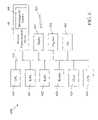
- FIG. 1Ais a block diagram of a wireless communication device in accordance with the present invention.
- the wireless communication deviceis fabricated as integrated circuit on a single semiconductor substrate.
- the wireless communication deviceincludes a reconfigurable antenna that can be dynamically configured to transmit and receive wireless signals at a plurality of frequencies.
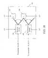
- FIG. 1Bis a detailed diagram of the switches in the reconfigurable antenna of FIG. 1A .
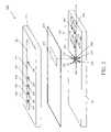
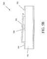
- FIG. 2is an exploded perspective of an implementation of the reconfigurable antenna of FIG. 1A .
- the reconfigurable antennais fabricated on two substrates separated by a ground plane.
- the reconfigurable antennaincludes an active portion that can be dynamically controlled to tune in to the plurality of frequencies, and a passive portion that are dedicated to resonate at one or more fixed frequencies.
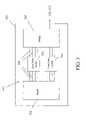
- FIG. 3shows another implementation of the active portion of the reconfigurable antenna in FIG. 2 .
- FIG. 4illustrates the effect of broadening resonance frequencies by adding a capacitive load and an inductive load to the reconfigurable antenna.
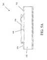
- FIG. 5Aillustrates a side view of a low-loss switch in an open position.
- FIG. 5Billustrates a side view of a low-loss switch in a close position.
- FIG. 6is a block diagram of a portable computer system for providing data management support in accordance with the present invention.
- FIG. 1Ashows a block diagram of a wireless communication device 100 in accordance with the present invention.
- the wireless communication device 100is an integrated CMOS device with radio frequency (RF) circuits, including wireless transceivers 105 , a processor core 150 including a baseband processor, and a memory system 170 .
- the processor core 150can be fabricated on a single semiconductor substrate or chip.
- the reconfigurable antenna 140as described below, can be dynamically configured by controlling the states of the switches 145 the to transmit and receive wireless signals at different band frequencies.
- the memory system 170can be a high-density memory array comprising various memory technologies such as flash memory and dynamic random access memory (DRAM), among others, on different portions of the memory array core.
- the memory system 170can also be fabricated on the same semiconductor substrate as the processor core 150 .
- the wireless transceivers 105include a cellular radio core 110 and a short-range wireless transceiver core 130 .
- the processor core 150can include one or more central processor units (CPU) 151 such as MIPS processors, one or more digital signal processors (DSPs) 153 , and a router 180 , among others. These processors 151 and 153 can be configured to operate optimally on specific problems. For example, the bank of DSPs 153 can be optimized to handle discrete cosine transforms (DCTs) or Viterbi encodings, among others. Additionally, Application Specific Integrated Circuits (ASICs) 155 can be provided to handle specific algorithms in silicon more efficiently than the programmable processors 151 and 153 . The number of active processors is controlled depending on the application, so that power is not used when it is not needed. This embodiment does not rely on complex clock control methods to conserve power, since the individual clocks are not run at high speed, but rather the unused processor is simply turned off when not needed.
- CPUcentral processor units
- DSPsdigital signal processors
- ASICsApplication Specific Integrated Circuits
- the processor core 150includes a controller 157 that can dynamically control the reconfigurable antenna 140 to enable it to transmit and receive wireless signals at different frequencies.
- the controller 157controls the open/close states of the switches 145 in the reconfigurable antenna 140 so that it resonates at the interest frequencies and filters out noises or other frequencies.
- the switches 145can include micro-electro-mechanical (MEM) switches (described below in relation to FIGS. 2 , 3 , 5 A and 5 B).
- MEMmicro-electro-mechanical
- FIG. 1Billustrates details of one implementation of the switches 145 .
- the switches 145include low-loss switches 194 , 196 as well as receiver switch 190 and transmission switch 192 .
- the receiver switch 190 and transmission switch 192are already present in the common antennas.
- the low loss switchesare also referred as diversity switches; they allow the device to receive from different spatial antenna configurations, improving noise characteristics.
- the receiver switch 190 , transmission switch 192 and low-loss switches 194 , 196are controlled by the controller 157 .
- the switching between different wireless frequenciescan be realized by configuring a combination of diversity switches and low-loss switches.
- the multiple uses of the pre-existing diversity switchesreduce the cost and the size of the reconfigurable antenna.
- the processor core 150also includes an analog circuit 160 for receiving the analog signals from the transceiver 105 and convert them into digital signals, as well as for converting digital signals to analog signals to be output to the transceiver 105 for transmission.
- One exemplary processor embedded in the processor core 150includes a register bank, a multiplier, a barrel shifter, an arithmetic logic unit (ALU) and a write data register.
- the exemplary processorcan handle DSP functions by having a multiply-accumulate (MAC) unit in parallel with the ALU.
- Embodiments of the processorcan rapidly execute multiply-accumulate (MAC) and add-compare-subtract (ACS) instructions in either scalar or vector mode.
- Other parts of the exemplary processorinclude an instruction pipeline, a multiplexer, one or more instruction decoders, and a read data register.
- a program counter (PC) registeraddresses the memory system 170 .
- a program counter controllerserves to increment the program counter value within the program counter register as each instruction is executed and a new instruction must be fetched for the instruction pipeline. Also, when a branch instruction is executed, the target address of the branch instruction is loaded into the program counter by the program counter controller.
- the processor core 150incorporates data pathways between the various functional units. The lines of the data pathways may be synchronously used for writing information into the core 150 , or for reading information from the core 150 . Strobe lines can be used for this purpose.
- instructions within the instruction pipelineare decoded by one or more of the instruction decoders to produce various core control signals that are passed to the different functional elements of the processor core 150 .
- the different portions of the processor coreconduct processing operations, such as multiplication, addition, subtraction and logical operations.
- the register bankincludes a current programming status register (CPSR) and a saved programming status register (SPSR).
- CPSRcurrent programming status register
- SPSRsaved programming status register
- the current programming status registerholds various condition and status flags for the processor core 150 . These flags may include processing mode flags (e.g. system mode, user mode, memory abort mode, etc.) as well as flags indicating the occurrence of zero results in arithmetic operations, carries and the like.
- the wireless communication device 100can detect and communicate with any wireless system it encounters at a given frequency.
- the router 180performs the switch in real-time through an engine that keeps track of the addresses of where the packets are going.
- the router 180can send packets in parallel through two or more separate pathways. For example, if a BluetoothTM connection is established, the router 180 knows which address it is looking at and will be able to immediately route packets using another connection standard. In doing this operation, the router 180 working with a digital sniffer program periodically scans its radio environment (‘ping’) to decide on optimal transmission medium.
- the router 180can send some packets in parallel through both the primary and secondary communication channel to make sure some of the packets arrive at their destinations.
- the processor core 150controls the cellular radio core 110 and the short-range wireless transceiver core 130 to provide a seamless dual-mode network integrated circuit that operates with a plurality of distinct and unrelated communications standards and protocols such as Global System for Mobile Communications (GSM), General Packet Radio Service (GPRS), Enhance Data Rates for GSM Evolution (Edge) and BluetoothTM.
- GSMGlobal System for Mobile Communications
- GPRSGeneral Packet Radio Service
- EdgeEnhance Data Rates for GSM Evolution
- BluetoothTMBluetoothTM.
- the cellular radio core 110provides wide area network (WAN) access
- WANwide area network
- LANlocal area network
- the processor core 150has embedded read-only-memory (ROM) containing software such as IEEE802.11 (including IEEE802.11a, IEEE802.11b, IEEE802.11g, etc.), GSM, GPRS, Edge, and/or BluetoothTM protocol software, among others.
- ROMread-only-memory
- the cellular radio core 110includes a transmitter/receiver section that is connected to the reconfigurable antenna 140 .
- the transmitter/receiver sectionis a direct conversion radio that includes an I/Q demodulator, transmit/receive oscillator/clock generator, multi-band power amplifier (PA) and power control circuit, and voltage-controlled oscillators and synthesizers.
- IFintermediate frequency
- the transmitter/receiver sectionconverts received signals into a first intermediate frequency (IF) by mixing the received signals with a synthesized local oscillator frequency and then translates the first IF signal to a second IF signal.
- the second IF signalis hard-limited and processed to extract an RSSI signal proportional to the logarithm of the amplitude of the second IF signal.
- the hard-limited IF signalis processed to extract numerical values related to the instantaneous signal phase, which are then combined with the RSSI signal.
- the combined signalsare processed by the processor core 150 to form PCM voice samples that are subsequently converted into an analog signal and provided to an external speaker or earphone.
- the processorsimply transfers the data over an input/output (I/O) port.
- I/Oinput/output
- an off-chip microphonecaptures analog voice signals, digitizes the signal, and provides the digitized signal to the processor core 150 .
- the processor core 150codes the signal and reduces the bit-rate for transmission.
- the processor core 150converts the reduced bit-rate signals to modulated signals such as I,I,Q,Q modulating signals, for example.
- the datais modulated and the modulated signals are then fed to the cellular telephone transmitter of the transmitter/receiver section.
- the short-range wireless transceiver core 130contains a radio frequency (RF) modem core 132 that communicates with a link controller core 134 .
- the processor core 150controls the link controller core 134 .
- the RF modem core 132has a direct-conversion radio architecture with integrated VCO and frequency synthesizer.
- the RF modem core 132includes an RF receiver connected to an analog-digital converter (ADC), which in turn is connected to a modem performing digital modulation, channel filtering, AFC, symbol timing recovery, and bit slicing operations.
- ADCanalog-digital converter
- the modemis connected to a digital to analog converter (DAC) that in turn drives an RF transmitter.
- DACdigital to analog converter
- the link controller core 134provides link control function and can be implemented in hardware or in firmware.
- One embodiment of the link controller core 134is compliant with the BluetoothTM specification and processes BluetoothTM packet types.
- the link controller core 134performs a header error check, scrambles the header to randomize the data and to minimize DC bias, and performs forward error correction (FEC) encoding to reduce the chances of getting corrupted information.
- the payloadis passed through a cyclic redundancy check (CRC), encrypted/scrambled and FEC-encoded.
- CRCcyclic redundancy check
- the FEC encoded datais then inserted into the header.
- a useris in his or her office and browses a web site on a portable computer through a wired local area network cable such as an Ethernet cable. Then the user walks to a nearby cubicle. As the user disconnects, the wireless communication device 100 initiates a short-range connection using a BluetoothTM connection. When the user drives from his or her office to an off-site meeting, the BluetoothTM connection is replaced with cellular telephone connection.
- the wireless communication device 100enables easy synchronization and mobility during a cordless connection, and open up possibilities for establishing quick, temporary (ad-hoc) connections with colleagues, friends, or office networks. Appliances using the wireless communication device 100 are easy to use since they can be set to automatically find and contact each other when within range.
- the short-range wireless transceiver core 130When the wireless communication device 100 is in the cellular telephone connection mode, the short-range wireless transceiver core 130 is powered down to save power. Unused sections of the chip are also powered down to save power. Many other battery-power saving features are incorporated, and in particular, the cellular radio core 110 when in the standby mode can be powered down for most of the time and only wake up at predetermined instances to read messages transmitted by cellular telephone base stations in the radio's allocated paging time slot.
- the cellular radio core 110uses idle time between its waking periods to activate the short-range wireless transceiver core 130 to search for a BluetoothTM channel signal. If BluetoothTM signals are detected, the phone sends a de-registration message to the cellular system and/or a registration message to the BluetoothTM system. Upon de-registration from the cellular system, the cellular radio core 110 is turned off or put into a deep sleep mode with periodic pinging and the short-range wireless transceiver core 130 and relevant parts of the synthesizer are powered up to listen to the BluetoothTM channel.
- the wireless communication device 100activates the cellular radio core 110 to establish a cellular link, using information from the latest periodic ping. If a cellular connection is established and BluetoothTM signals are weak, the wireless communication device 100 sends a de-registration message to the BluetoothTM system and/or a registration message to the cellular system. Upon registration from the cellular system, the short-range wireless transceiver core 130 is turned off or put into a deep sleep mode and the cellular radio core 110 and relevant parts of the synthesizer are powered up to listen to the cellular channel.
- the router 180can send packets in parallel through the separate pathways of cellular or BluetoothTM. For example, if a BluetoothTM connection is established, the router 180 knows which address it is looking at and will be able to immediately route packets using another connection standard. In doing this operation, the router 180 pings its environment to decide on optimal transmission medium. If the signal reception is poor for both pathways, the router 180 can send some packets in parallel through both the primary and secondary communication channel (cellular and/or BluetoothTM) to make sure some of the packets arrive at their destinations. However, if the signal strength is adequate, the router 180 prefers the BluetoothTM mode to minimize the number of subscribers using the capacity-limited and more expensive cellular system at any give time. Only a small percentage of the wireless communication device 100 , those that are temporarily outside the BluetoothTM coverage, represents a potential load on the capacity of the cellular system, so that the number of mobile users can be many times greater than the capacity of the cellular system alone could support.
- the reconfigurable antenna 140includes an active portion that can be dynamically controlled to tune in to the plurality of frequencies, and a passive portion that is dedicated to resonate at fixed frequencies.
- FIG. 2is an exploded perspective of an implementation of the reconfigurable antenna 140 of FIG. 1A .
- the reconfigurable antenna 140is fabricated on a first substrate 215 and a second substrate 220 separated by a conducting layer (a ground plane 230 ).
- the first substrate 215includes multiple antenna bodies and multiple poles that can be dynamically configured to resonate at a multiple of frequencies compatible with different communication protocols.
- the frequency rangesare preferably (but not limited to) centered at 900 MHz, 1570 MHz, 1800 MHz, 1900 MHz, 2400 MHz, and 5700 MHz.
- the second substrate 220includes frequency matching stubs, which resonate at fixed frequencies (i.e. the passive portion of the reconfigurable antenna).
- the second substrate 220also includes a configurable filter 280 that can be actively configured to filter out noises from unwanted frequencies.
- a transmission line 210is printed on a first substrate 215 .
- a main antenna body 221 and a series of secondary antenna bodies 222 – 226are printed on a separate second substrate 220 .
- a common ground plane 230is located between the two substrates. Communication signals pass between the transmission line 210 and the main antenna body 221 through an aperture 232 in the ground plane 230 .
- the ground plane 230shields the radiating energy from the transmission line 210 so that it will not couple into the main antenna body 221 and the secondary antenna bodies 222 – 226 .
- the switches 145include low-loss switches 241 – 245 that connect the main antenna body 221 and the secondary antenna bodies 222 – 226 .
- the reconfigurable antenna 140can be dynamically configured to resonate at different frequencies by selectively opening or closing low-loss switches 241 – 245 .
- the low-loss switch 241is open, the main antenna body 221 is electrically isolated from all the secondary antenna bodies 222 – 226 .
- the effective antenna length of the reconfigurable antenna 140is the length of the main antenna body 221 .
- the length of the main antenna body 221is chosen to be half wavelength at 5700 MHz, which allows the wireless signals at 5700 MHz to resonant in the main antenna body 221 .
- the main antenna body 221 and the secondary antenna body 222are electrically connected, but they are isolated from the rest of the secondary antenna bodies 223 – 226 .
- the effective antenna length of the reconfigurable antenna 140is then the length of the main antenna body 221 plus the length of the secondary antenna body 222 , which corresponds to half wavelength at 2400 MHz.
- the electrically connected main antenna body 221 and the secondary-antenna body 222have their resonant frequency at 2400 MHz.
- the low-loss switchesare preferably micro-electro-mechanical (MEM) switches, as illustrated in FIGS. 5A and 5B below.
- MEM switcheshave a very low insertion loss when closed and a high isolation value when open.
- Other types low-loss switchesinclude p-HEMT (High Electron Mobility Transistor) switches such as gallium arsenide semiconductor switches.
- Table 1summarizes the configurations of the low-loss switches 241 – 245 at each of the resonant frequencies of the reconfigurable antenna 140 at 900 MHz, 1570 MHz, 1800 MHz, 1900 MHz, 2400 MHz, and 5700 MHz.
- the effective length of the antenna body in each configurationcorresponds to half wavelength at the corresponding frequency.
- the open and close states of the low-loss switches 241 – 245are dynamically controlled by the controller 157 as instructed by the processor core 150 so that the resonance frequency of the reconfigurable antenna 140 is always tuned to match the frequency mode of the wireless communication device 100 .
- the transmission line 210is terminated by frequency matching stubs 251 , 252 , 253 , 254 , 255 , 256 that join the transmission line 210 at a stub junction 260 .
- the frequency matching stubs 251 – 256respectively corresponding to 900 MHz, 1570 MHz, 1800 MHz, 1900 MHz, 2400 MHz, and 5700 MHz.
- Each of frequency matching stubs 251 – 256is designed so that their lengths are respectively one-quarter wavelengths of their corresponding frequencies.
- the frequency-matching stub 251has a length of one-quarter of the wavelength at 5700 MHz.
- the frequency-matching stub 256has the length of one-quarter wavelength at 900 MHz.
- a frequency-matching stubgenerates a short circuit at the entrance to the stub when a signal having a wavelength four times the stub length passes through the stub. For example, when a signal at 1900 MHz passes through the transmission line 210 and the frequency matching stub 253 , the frequency matching stub 253 creates a short circuit at the stub junction 260 , which allows maximum power flow between the transmission line 210 and the main antenna body 221 .
- the angle between the matching stubs 251 – 256is desirable to keep the angle between the matching stubs 251 – 256 as large as possible.
- the large angular separationalso minimizes the size of the stub junction 260 .
- the finite size of the stub junction 260produces non-ideal impedances to the reconfigurable antenna 140 .
- the lengths of the frequency-matching stub 251 – 256need to be adjusted from the ideal one-quarter wavelength to correct for these non-ideal factors.
- each of the frequency matching stubs 251 – 256is approximately 52 degrees away from the neighboring stub and the transmission line 210 .
- the effective antenna lengthis dynamically configured to tune in a large dynamic range by switching the low-loss switches 241 – 245 .
- the reconfigurable antenna 140includes a combination of active and passive antennas.
- the passive antennaprovides sharp resonance peaks in the rejection ratio at a subset of interested frequencies, while the dynamic antenna provides capability of changing tuning frequency to a drastically different frequency.
- the combination of active and passive antennasfurther broadens the range of the resonance frequencies.
- the reconfigurable antenna 140can therefore be tuned into-wireless communication bands at drastic different frequencies.
- the different frequency bands in the example of Table 1different by at least ten percent or larger in percentage of the number of cycles per second at each frequency.
- the length for the aperture 232is designed to maximize antenna performance.
- the aperture 232is chosen to be equal to one-half of the wavelength of the highest frequency, that is, 5700 MHz in the particular implementation described herein.
- the one-half of a wavelengthis optimal for maximum power transfer at 5700 MHz.
- the shortest wavelengthis chosen to prevent higher order modes from appearing on any shorter wavelength signals.
- the aperture 232 having one-half of the wavelength at 5700 MHzis too short to allow a full half-wavelength of the longer wavelength signals (at 900 MHz, 1570 MHz, 1800 MHz, 1900 MHz, and 2400 MHz) to appear in the aperture 232 .
- Such inductive effect of the aperture 232can be compensated by shortening the frequency-matching stub 252 – 256 to less than one-quarter wavelength. The stub lengths could be reduced enough to allow the capacitive components of the frequency matching stubs 252 – 256 to resonate out the inductive component of the aperture 232 .
- the reconfigurable antenna 140can be fabricated using printed circuit technology.
- the transmission line 210 and the frequency matching stubs 251 – 256may be printed directly onto a circuit board that serves as the first substrate 215 .
- the main antenna body 221 and the secondary antenna bodies 222 – 226may be printed onto a second circuit board that will serve as the second substrate 220 .
- the low-loss switches 241 – 245can be fabricated on a semiconductor wafer and die cut, inserted onto the printed circuit board serving as the second substrate 220 .
- the ground plane 230may be printed on either circuit board.
- a low loss adhesiveis used to bond the first substrate 215 and the second substrate 220 together.
- the coupling between different frequency bandscan be reduced further by a configurable filter 280 printed on the second substrate 220 ( FIG. 2 ).
- Signals received by the antenna bodies 221 – 226are coupled into the stub junction 260 .
- the signalsthen pass through the transmission line 210 and output to the amplifier in the wireless transceivers 105 .
- the impedance of the filter 280is a function of the frequency of the signal passing through the transmission line 210 .
- the configurable filter 280reduces the magnitude of the signals at some frequencies while allowing other frequency signals to pass relatively unimpeded.
- Filter stubs 282 , 284 , 286are connected to the transmission line 210 at a stub injunctions by low-loss switches 292 , 294 , 296 (included the group of switches 145 ).
- the transmission line 210is electrically isolated from the filter stubs 282 , 284 , 286 .
- the only impedance affecting the signalis the impedance of the transmission line 210 . This impedance is determined primarily by the geometry of the transmission line 210 and the frequency of the signal.
- the filter stub 282When the low-loss switch 292 is closed by the controller 157 , the filter stub 282 is electrically connected to the transmission line 210 . The filter stub 282 is then in parallel with the section of the transmission line 210 that follows. The impedance of the filter stub 282 will be, therefore, in parallel with the impedance of the transmission line 210 that follows the stub junction of the filter stub 282 . This will alter the impedance of the configurable filter 280 as seen by a signal entering the transmission line 210 , causing the configurable filter 280 to pass and/or block different frequencies.
- the low-loss switchescan also be located inside of the filter stubs 282 , 284 , 286 .
- a filter stubcan also have more than one low-loss switch.
- two low-loss switches 294 , 298provide two electric conductive lengths of filter stub 284 .
- the filter stub 284has a short conductive length when the low-loss switch 294 is closed while low-loss switch 298 is open, and a longer stub length when both low-loss switches 294 , 298 are closed.
- the locations of the filter stubs, the number and the locations of the low-loss switches 292 , 294 , 296 , 298 as well as the geometries of the filter stubs 282 , 284 , 286 and transmission line 210different frequencies can be impeded or while the others unimpeded at different low-loss switch configurations.
- the different of close/open states of the low-loss switches 292 – 298result in a plurality of filter configurations, each of which allows one of the signal frequency 900 MHz, 1570 MHz, 1800 MHz, 1900 MHz, 2400 MHz, and 5700 MHz to pass relatively unimpeded while the other frequencies blocked. This resulted in a reduction of unwanted signals from different frequency bands when the reconfigurable antenna 140 is tuned into one frequency band.
- the switchings between different wireless communication bandscan be made automatically and seamlessly to the users.
- the need for band (and/or protocol) switchingcan be caused a drop in signal strength in one protocol or mode. For example, if the short-range wireless transceiver core 130 in the idle mode detects that BluetoothTM signals have dropped in strength.
- the wireless communication device 100activates the cellular radio core 110 to establish a cellular link while the controller 157 dynamically controls the open and close states of the low-loss switches 241 – 245 and low-loss switches 292 – 298 so that the reconfigurable antenna 140 is tuned to the cellular frequency for the new connection.
- the cellular connectionis established, the wireless communication device 100 deregisers from the BluetoothTM system and registers to the cellular system.
- the signals from the BluetoothTM systemare now filtered out by the reconfigurable antenna 140 .
- FIG. 3shows another implementation of the active portion of the reconfigurable antenna 140 which is fabricated on the first substrate 215 of the reconfigurable antenna 140 ( FIG. 2 ).
- the active antenna 300includes two electrode patches 310 and 320 (or antenna bodies), a series of narrow conductive lines 360 that connect the electrode patches 310 and 320 , and low-loss switches 330 and 340 that control the connections.
- the electrode patch 320is fed to the aperture 232 in the ground plane 230 and the transmission line 210 on the second substrate 220 .
- the electrode patches 310 and 320 and the narrow conductive lines 360can be printed directly onto a circuit boards that serves as the first substrate 215 .
- the low-loss switches 330 and 340can be fabricated on a semiconductor wafer, die cut and inserted onto the printed circuit board. This design takes advantage of the fact that current in a shaped patch antenna typically flows in a laminar form in only one dimension. This means the current can be directed by the narrow conductive lines 360 between the electrode patches 310 , 320 without losing the desired radiation pattern. The narrow conductive lines result in a decrease in the resonance frequency due to increased inductance and decreased capacitance.
- the compact design shown in FIG. 3enables the miniaturization of the wireless device 100 .
- a major problem faced by wireless systemsis the antenna size.
- An efficient antennatypically requires a size larger than about 1 ⁇ 2 of the wavelength. For GSM at 800 MHz, this translates to about 20 cm, which is longer than the design constraints of the most of the wireless devices.
- the low-loss switchesare reused to low cost and reduce device dimensions as well as manufacture complexity.
- the low-loss switches 330 , 340can be the diversity switch and transceiver/receiver switches that are already existence in the common antenna. Furthermore, the low-loss switches 330 , 340 are shared among a plurality of narrow conductive lines 360 , which reduces the number of components and thus cost.
- the designcombines innovative geometries with sophisticated loading and switching schemes, re-using the same components that are already present on current wireless devices. This reconfigurable antenna in this design first tune to the neighborhood of a carrier frequency, and then follow the carrier frequency by adjusting antenna gain (versus adjusting frequency as in PLL).
- the frequency tracking and band switchingcan be made real time with the baseband processor in the processor core 150 selecting antenna configurations based on signal strength and signal type. For example, in the case of a switch between 802.11b and GPRS, a dual-frequency antenna (900 MHz and 2.4 GHz) can operate at narrowband during one of the empty GPRS time slots.
- the processor core 150examines the presence and the strength of the signals at the 2.4 GHz frequency in a narrowband mode. If the signals are present and strong enough, the whole antenna is switched to a wideband mode to allow for 802.11b proper demodulation.
- the receiveris capable of tuning in a specific narrow-band frequency by slightly varying the antenna loading (thus the resonance frequency).
- the variable antenna loadingcan be implemented on the RF chip or the power amplifier, which can be controlled by the baseband chip (processor core 150 ). This is achieved by varying the capacitance of a variable capacitor mounted on the antenna or on the power amplifier with very low loss in the system.
- GSMGlobal System for Mobile Communications
- the capability of narrowband selectioncan also be applied to aid in frequency hopping systems such as BluetoothTM.
- the carrier frequencyhops 1600 times per second in BluetoothTM, with 1–2 MHz bandwidth per hop.
- the system bandwidth requiredis 70 MHz.
- the signal strengths in a frequency-hopping wireless modeare detected in a narrowband mode so that the antenna parameters can be adjustably optimized before each frequency hop. As a result, the signal-to-noise ratio of BluetoothTM can be considerably.
- FIG. 4illustrates the effect of the broadening resonance frequencies by adding a capacitive load and an inductive load to the reconfigurable antenna. As shown, the rejection ratio in the unloaded antenna has a narrow negative resonance peak. Two additional resonance frequencies can be added above and below the unloaded resonance by adding a capacitive load and an inductive load to the antenna. The addition of the capacitive and inductive loads effectively increases the bandwidth by a factor of three.
- the operating frequency ranges of the reconfigurable antenna 140can be further broadened by being used in combination with raised patch antenna, PCB patch antenna, quarter wave movable antenna such as helical antenna, etc.
- FIG. 5A and FIG. 5Brespectively show the side views of the low-loss switch 241 in ‘open’ and ‘close’ positions.
- the low-loss switch 241may be fabricated using standard integrated circuit technology.
- the low-loss switch 241is constructed on a substrate 500 .
- GaAsis used as the substrate 500 .
- Other materials, such as InP, silicon, quartz, or even ceramicsmay also be used.
- On top of the substrate 500is an input line 502 , an output line 504 , an armature 506 , and a substrate electrode 508 .
- the open position of low-loss switch 241as shown in FIG.
- low-loss switches 242 – 245 , 261 – 263can also be similarly fabricated.
- FIG. 6illustrates an exemplary portable computer system 600 equipped with the wireless communication device 100 .
- the portable computer system 600is preferably housed in a small, rectangular portable enclosure.
- a general-purpose architecture for entering information into the data management by writing or speaking to the computer systemis illustrated.
- a computer processor 620 or central processing unit (CPU)provides the processing capability.
- the computer processor 620can be a reduced instruction set computer (RISC) processor or a complex instruction set computer (CISC) processor.
- RISCreduced instruction set computer
- CISCcomplex instruction set computer
- the computer processor 620is a low power CPU such as the MC68328V DragonBall device available from Motorola Inc.
- the computer processor 620is connected to a read-only-memory (ROM) 621 for receiving executable instructions as well as certain predefined data and variables.
- the computer processor 620is also connected to a random access memory (RAM) 622 for storing various run-time variables and data arrays, among others.
- the RAM 622is sufficient to store user application programs and data. In this instance, the RAM 622 can be provided with a back-up battery to prevent the loss of data even when the computer system is turned off.
- non-volatile memorysuch as a programmable ROM such as an electrically erasable programmable ROM, a flash ROM memory in addition to the ROM 621 for data back-up purposes.
- the portable computer system 600has built-in applications stored in the ROM 621 or downloadable to the RAM 622 which include, among others, an appointment book to keep track of meetings and to-do lists, a phone book to store phone numbers and other contact information, a notepad for simple word processing applications, a world time clock which shows time around the world and city locations on a map, a database for storing user specific data, a stopwatch with an alarm clock and a countdown timer, a calculator for basic computations and financial computations, and a spreadsheet for more complex data modeling and analysis. Additionally, project planning tools, and CAD/CAM systems, Internet browsers, among others, may be added to increase the functionality of portable computing appliances. Users benefit from this software, as the software allows users to be more productive when they travel as well as when they are in their offices.
- the portable computer system 600receives instructions from the user via one or more switches such as push-button switches in a keypad 624 .
- the computer processor 620is also connected to a real-time clock/timer 625 that tracks time.
- the real-time clock/timer 625can be a dedicated integrated circuit for tracking the real-time clock data, or alternatively, the real-time clock/timer 625 can be a software clock where time is tracked based on the clock signal clocking the computer processor 620 .
- the software clock/timerbe interrupt driven to minimize the CPU loading.
- an interrupt-driven software real-time clock/timer 625requires certain CPU overhead in tracking time.
- the real-time clock/timer integrated circuit 625is preferable where high processing performance is needed.
- the computer processor 620drives an internal bus 626 .
- the computer systemcan access data from the ROM 621 or RAM 622 , or can acquire I/O information such as visual information via a charged-coupled-device (CCD) sensor 628 .
- CCDcharged-coupled-device
- the CCD sensor 628is further connected to a lens assembly (not shown) for receiving and focusing light beams to the CCD sensor 628 for digitization. Images scanned via the CCD sensor 628 can be compressed and transmitted via a suitable network such as the Internet, through BluetoothTM channel, cellular telephone channels or via facsimile to a remote site.
- the computer processor 620is connected to the wireless communication device 100 that embodies a reconfigurable antenna 140 .
- the wireless communication device 100satisfies the need to access electronic mail, paging, mode/facsimile, remote access to home computers and the Internet. Because the wireless communication device 100 can dynamically tune into a wide range of frequency bands at high fidelity, the portable computer system 600 can communicate with other device using a plurality of wireless protocols.
- One simple form of wireless communication device 100is a wireless link to a cellular telephone where the user simply accesses a cellular channel similar to the making of a regular voice call.
- One channelis dedicated to voice calls because the latency and low packet reliability in data channels are not suitable for voice communications.
- GPRSprovides 8 channels per user with one being dedicated to voice and independent of the data connection.
- the computer processor 620 of the preferred embodimentaccepts handwritings as an input medium from the user.
- a digitizer 634 , a pen 633 , and a display 635are provided to capture the handwriting.
- the digitizer 634has a character input region and a numeral input region that are adapted to capture the user's handwritings on words and numbers, respectively.
- the display 635has a viewing screen exposed along one of the planar sides of the enclosure are provided.
- the displaycan be a Liquid Crystal Display or (LCD) or Organic Light Emitting Diode (OLED) Display.
- LCDLiquid Crystal Display
- OLEDOrganic Light Emitting Diode
- the display 635When operating as an output device, the display 635 displays computer-generated images developed by the CPU 620 . The display 635 also provides visual feedback to the user when one or more application software execute.
- the digitizer 634senses the position of the tip of the stylus or pen 633 on the display 635 and provides this information to the computer processor 620 .
- the present inventioncontemplates that display assemblies capable of sensing the pressure of the stylus on the screen can be used to provide further information to the CPU 620 .
- the CPU 620accepts pen strokes from the user using the stylus or pen 633 that is positioned over the digitizer 634 .
- the position of the pen 633is sensed by the digitizer 634 via an electromagnetic field as the user writes information to the computer system.
- the digitizer 634converts the position information to graphic data. For example, graphical images can be input into the pen-based computer by merely moving the stylus over the surface of the screen.
- the CPU 620senses the position and movement of the stylus, it generates a corresponding image on the screen to create the illusion that the pen or stylus is drawing the image directly upon the screen.
- the data on the position and movement of the stylusis also provided to handwriting recognition software, which is stored in the ROM 621 and/or the RAM 622 .
- the handwriting recognizersuitably converts the written instructions from the user into text data suitable for saving time and expense information. The process of converting the pen strokes into equivalent characters and/or drawing vectors using the handwriting recognizer is described below.
- the computer systemis also connected to one or more input/output (I/O) ports 642 which allow the CPU 620 to communicate with other computers.
- I/O ports 642may be a parallel port, a serial port, a universal serial bus (USB) port, a Firewire port, or alternatively a proprietary port to enable the computer system to dock with the host computer.
- USBuniversal serial bus
- Firewire portor alternatively a proprietary port to enable the computer system to dock with the host computer.
- the I/O port 642is housed in a docking port, after docking, the I/O ports 642 and software located on a host computer (not shown) support an automatic synchronization of data between the computer system and the host computer.
- the synchronization softwareruns in the background mode on the host computer and listens for a synchronization request or command from the portable computer system 600 of the present invention. Changes made on the computer system and the host computer will be reflected on both systems after synchronization. Preferably, the synchronization software only synchronizes the portions of the files that have been modified to reduce the updating times.
- the I/O port 642is preferably a high speed serial port such as an RS-232 port, a Universal Serial Bus, or a Fiber Channel for cost reasons, but can also be a parallel port for higher data transfer rate.
- One or more portable computer systems 600can be dispersed in nearby cell regions and communicate with a cellular mobile support station (MSS) as well as a BluetoothTM station.
- MSScellular mobile support station
- BluetoothTM stationsrelay the messages via stations positioned on a global basis to ensure that the user is connected to the network, regardless of his or her reference to home.
- the stationsare eventually connected to the Internet, which is a super-network, or a network of networks, interconnecting a number of computers together using predefined protocols to tell the computers how to locate and exchange data with one another.
- the primary elements of the Internetare host computers that are linked by a backbone telecommunications network and communicate using one or more protocols.
- the most fundamental of Internet protocolsis called Transmission Control Protocol/Internet Protocol (TCP/IP), which is essentially an envelope where data resides.
- TCP/IPTransmission Control Protocol/Internet Protocol
- the TCP protocoltells computers what is in the packet, and the IP protocol tells computers where to send the packet.
- the IPtransmits blocks of data called datagrams from sources to destinations throughout the Internet. As packets of information travel across the Internet, routers throughout the network check the addresses of data packages and determine the best route to send them to their destinations. Furthermore, packets of information are detoured around non-operative computers if necessary until the information finds its way to the proper destination.
- the Webis based on a client/server model where Web pages reside on host computers that “serve up” pages when the user's computer (client computer) requests them.
- client computerAs the user “surfs” the Web, a browser can request data from the database on a server computer that processes and replies the desired data back to the computer system of FIG. 6 and to display that request when the request is fulfilled by the server.
- the client computerruns a browser software which asks for specific information by sending a HTTP request across the Internet 150 connection to the host computer. When the host computer receives the HTTP request, it responds by sending the data back to the client.
- the browsercommonly features a graphical user interface with icons and menus across the top along with a field to supply the URL for retrieval purposes.
- Navigational buttonsguide the users through cyberspace in a linear manner, either one page forward or backward at a time.
- Pull down menusprovide a history of sites accessed so that the user can revisit previous pages.
- a stop buttonis typically provided to cancel the loading of a page.
- a bookmarkis provided to hold the user's favorite URLs in a list such as a directory tree.
- the browsertypically provides a temporary cache on the data storage device or in RAM. The cache allows a more efficient Internet access as it saves bandwidth and improves access performance significantly.
- the browseralso interprets HyperText Markup Language (HTML) which allows web site creators to specify a display format accessible by HTML compatible browsers.
- HTMLHyperText Markup Language
- TCP/IPopens a connection between the host and client computers.
- the browserthen generates a request header to ask for a specific HTML document.
- the serverresponds by sending the HTML document as text to the client via the TCP/IP pipeline.
- the client computeracknowledges receipt of the page and the connection is closed.
- the HTML documentis stored in the browser's cache.
- the browserthen parses the HTML document for text and tags. If the browser runs across tags that link to images/pictures and sounds, the browser makes separate requests for these files to the server and displays or generates sounds to the user.
- a languagesuch as Java may be utilized. Java was developed originally by Sun Microsystems of Mountain View, Calif.
- JavaThe specification for the Java language is stored at the Java web site http://java.sun.com/.
- the web sitecontains the Java development software, a HotJava web browser, and on-line documentation for all aspects of the Java language, hereby incorporated by reference.
- Javacan download and play applets on a browser system of the receiver, or reader.
- Appletsare Java programs that are downloaded over the Internet World Wide Web, as dictated by a tag such as ⁇ applet> tags and executed by a Web browser on the reader's machine.
- the compilertakes the instructions and generates bytecodes, which are system independent machine codes.
- a bytecode interpreterexecutes the bytecodes.
- the bytecode interpretercan execute stand-alone, or in the case of applets, the bytecode interpreter is built-in Java compatible browsers.
- the Internetis transformed from a passive giant book of information into an active network capable of supporting electronic commerce and virtual ecosystems.
- the portable computer system 600allows users to move about freely within and between cells while transparently maintaining all connections, particularly with the Internet.
Landscapes
- Engineering & Computer Science (AREA)
- Computer Networks & Wireless Communication (AREA)
- Signal Processing (AREA)
- Physics & Mathematics (AREA)
- Electromagnetism (AREA)
- Transceivers (AREA)
Abstract
Description
- a) a reconfigurable antenna that can be dynamically configured to transmit and receive wireless signals at a plurality of frequencies and bandwidths;
- b) one or more wireless transceivers coupled to the antenna; and
- c) a processor core coupled to the reconfigurable antenna and the wireless transceivers, for dynamically controlling the configurations of the reconfigurable antenna and processing the wireless signals transmitted and received at the plurality of frequencies.
| TABLE 1 |
| Low-loss Switch Configurations for Tuning Different Antenna Frequencies |
| Low-loss | Low-loss | Low-loss | Low-loss | Low-loss | ||
| Switch | Switch | Switch | Switch | |||
| 241 | 242 | 243 | 244 | 245 | ||
| 5700 MHz | Open | Open | Open | Open | Open |
| 2400 MHz | Closed | Open | Open | Open | Open |
| 1900 MHz | Closed | Closed | Open | Open | Open |
| 1800 MHz | Closed | Closed | Closed | Open | Open |
| 1570 MHz | Closed | Closed | Closed | Closed | Open |
| 900 MHz | Closed | Closed | Closed | Closed | Closed |
- 100 wireless communication device
- 105 transceiver
- 110 cellular radio core
- 130 short-range wireless transceiver core
- 132 radio frequency (RF) modem core
- 134 link controller core
- 140 reconfigurable antenna
- 145 switch
- 150 processor core
- 151 central processor unit (CPU)
- 153 digital signal processor (DSP)
- 155 Application Specific Integrated Circuit (ASIC)
- 160 analog circuit
- 170 memory system
- 180 router
- 190 receiver switch
- 192 transmission switch
- 194 low-loss switch
- 196 low-loss switch
- 210 transmission line
- 215 first substrate
- 220 second substrate
- 221 main antenna body
- 222 secondary antenna body
- 223 secondary antenna body
- 224 secondary antenna body
- 225 secondary antenna body
- 226 secondary antenna body
- 230 ground plane
- 232 aperture
- 241 low-loss switch
- 242 low-loss switch
- 243 low-loss switch
- 244 low-loss switch
- 245 low-loss switch
- 251 frequency matching stub
- 252 frequency matching stub
- 253 frequency matching stub
- 254 frequency matching stub
- 255 frequency matching stub
- 256 frequency matching stub
- 260 stub junction
- 280 configurable filter
- 282 filter stub
- 284 filter stub
- 286 filter stub
- 292 low-loss switch
- 294 low-loss switch
- 296 low-loss switch
- 298 low-loss switch
- 300 active antenna
- 310 electrode patch
- 320 electrode patch
- 330 low-loss switch
- 340 low-loss switch
- 360 narrow conductive lines
- 500 substrate
- 502 input line
- 504 output line
- 506 armature
- 508 substrate electrode
- 600 portable computer system
- 620 computer processor
- 621 read only memory (ROM)
- 622 random access memory (RAM)
- 624 keypad
- 625 real-time clock/timer
- 626 bus
- 628 charge couple device (CCD) sensor
- 633 stylus pen
- 634 digitizer
- 635 display
- 642 input/output ports (I/O)
Claims (16)
Priority Applications (2)
| Application Number | Priority Date | Filing Date | Title |
|---|---|---|---|
| US10/155,485US7260424B2 (en) | 2002-05-24 | 2002-05-24 | Dynamically configured antenna for multiple frequencies and bandwidths |
| US11/805,231US7610070B2 (en) | 2002-05-24 | 2007-05-22 | Dynamically configured antenna for multiple frequencies and bandwidths |
Applications Claiming Priority (1)
| Application Number | Priority Date | Filing Date | Title |
|---|---|---|---|
| US10/155,485US7260424B2 (en) | 2002-05-24 | 2002-05-24 | Dynamically configured antenna for multiple frequencies and bandwidths |
Related Child Applications (1)
| Application Number | Title | Priority Date | Filing Date |
|---|---|---|---|
| US11/805,231ContinuationUS7610070B2 (en) | 2002-05-24 | 2007-05-22 | Dynamically configured antenna for multiple frequencies and bandwidths |
Publications (2)
| Publication Number | Publication Date |
|---|---|
| US20030219035A1 US20030219035A1 (en) | 2003-11-27 |
| US7260424B2true US7260424B2 (en) | 2007-08-21 |
Family
ID=29549076
Family Applications (2)
| Application Number | Title | Priority Date | Filing Date |
|---|---|---|---|
| US10/155,485Expired - LifetimeUS7260424B2 (en) | 2002-05-24 | 2002-05-24 | Dynamically configured antenna for multiple frequencies and bandwidths |
| US11/805,231Expired - LifetimeUS7610070B2 (en) | 2002-05-24 | 2007-05-22 | Dynamically configured antenna for multiple frequencies and bandwidths |
Family Applications After (1)
| Application Number | Title | Priority Date | Filing Date |
|---|---|---|---|
| US11/805,231Expired - LifetimeUS7610070B2 (en) | 2002-05-24 | 2007-05-22 | Dynamically configured antenna for multiple frequencies and bandwidths |
Country Status (1)
| Country | Link |
|---|---|
| US (2) | US7260424B2 (en) |
Cited By (227)
| Publication number | Priority date | Publication date | Assignee | Title |
|---|---|---|---|---|
| US20050057421A1 (en)* | 2003-09-16 | 2005-03-17 | Farrokh Mohamadi | Direct downlink RF module |
| US20060146849A1 (en)* | 2004-12-30 | 2006-07-06 | Alan Stone | Parallel processing data transfer arrangements |
| US20060240785A1 (en)* | 2002-08-29 | 2006-10-26 | Harald Fischer | Transceiver apparatus for use in a multi-frequency communication system, base station of a multi-frequency communication system, method for use of the transceiver apparatus, method of transceiving a multi-frequency signal in a multi-frequency communication system |
| US20070164868A1 (en)* | 2005-12-14 | 2007-07-19 | Deavours Daniel D | Microstrip antenna for rfid device |
| US20070183116A1 (en)* | 2006-01-24 | 2007-08-09 | Stmicroelectronics S.R.L. | Micro-electro-mechanical variable capacitor for radio frequency applications with reduced influence of a surface roughness |
| US20080001823A1 (en)* | 2006-07-03 | 2008-01-03 | Samsung Electronics Co., Ltd. | Antenna capable of micro-tuning and macro tuning for wireless terminal |
| US20080039043A1 (en)* | 2004-07-26 | 2008-02-14 | Matsushita Electric Industrial Co., Ltd. | Mobile Telephone Device |
| US20080081577A1 (en)* | 2006-09-29 | 2008-04-03 | Ahmadreza Rofougaran | Method and system for utilizing diplexer/duplexer for wcdma operation as a filter for supporting gsm-based operation |
| US20080081582A1 (en)* | 2006-09-29 | 2008-04-03 | Ahmadreza Rofougaran | Method and system for dynamically tuning and calibrating an antenna using antenna hopping |
| US20080080452A1 (en)* | 2006-09-29 | 2008-04-03 | Ahmadreza Rofougaran | Method and system for diversity processing based on antenna switching |
| US20080080418A1 (en)* | 2006-09-29 | 2008-04-03 | Ahmadreza Rofougaran | Method and system for antenna architecture for wcdma/hsdpa/hsudpa diversity and enhanced gsm/gprs/edge performance |
| US20080080453A1 (en)* | 2006-09-29 | 2008-04-03 | Ahmadreza Rofougaran | Method and system for sharing rf filters in systems supporting wcdma and gsm |
| US20080200131A1 (en)* | 2002-07-16 | 2008-08-21 | Franca-Neto Luiz M | Chip package with transceiver front-end |
| US20080287071A1 (en)* | 2007-05-16 | 2008-11-20 | Wistron Neweb Corp. | Expandable wireless transceiver |
| US20090073076A1 (en)* | 2007-09-13 | 2009-03-19 | Sony Ericsson Mobile Communications Ab | Adaptive antenna matching |
| US20090156120A1 (en)* | 2007-12-12 | 2009-06-18 | Ahmadreza Rofougaran | Method and system for portable data storage with integrated 60 ghz radio |
| US20090153428A1 (en)* | 2007-12-12 | 2009-06-18 | Ahmadreza Rofougaran | Method and system for a phased array antenna embedded in an integrated circuit package |
| US20090157927A1 (en)* | 2007-12-12 | 2009-06-18 | Ahmadreza Rofougaran | Method and system for chip-to-chip communications with wireline control |
| US20090156276A1 (en)* | 2007-12-12 | 2009-06-18 | Ahmadreza Rofougaran | Method and system for sharing antennas for high frequency and low frequency applications |
| US20090221313A1 (en)* | 2008-02-28 | 2009-09-03 | Ahmadreza Rofougaran | Method and system for a multistandard proxy |
| US20090247213A1 (en)* | 2008-03-27 | 2009-10-01 | Ahmadreza Rofougaran | Method and system for frequency-shift based chip-to-chip communications |
| US20090243740A1 (en)* | 2008-03-27 | 2009-10-01 | Ahmadreza Rofougaran | Method and system for reduced jitter signal generation |
| US20090248929A1 (en)* | 2008-03-27 | 2009-10-01 | Ahmadreza Rofougaran | Method and system for inter-pcb communications with wireline control |
| US20090280768A1 (en)* | 2008-05-07 | 2009-11-12 | Ahmadreza Rofougaran | Method And System For Inter IC Communications Utilizing A Spatial Multi-Link Repeater |
| US7627291B1 (en)* | 2005-01-21 | 2009-12-01 | Xilinx, Inc. | Integrated circuit having a routing element selectively operable to function as an antenna |
| US20090316846A1 (en)* | 2008-06-19 | 2009-12-24 | Ahmadreza Rofougaran | Method and system for 60 ghz wireless clock distribution |
| US20090318086A1 (en)* | 2008-06-19 | 2009-12-24 | Ahmadreza Rofougaran | Method and system for frequency-shift based pcb-to-pcb communications |
| EP2169764A1 (en) | 2008-09-26 | 2010-03-31 | Commissariat A L'energie Atomique | Transmit/receive radiofrequency antenna with modifiable transmit/receive parameters |
| US20100111046A1 (en)* | 2004-12-13 | 2010-05-06 | Van Rooyen Pieter Gert Wessel | Method and System for Mobile Receiver Antenna Architecture for European Band Cellular and Broadcasting Services |
| US20100201511A1 (en)* | 2009-02-11 | 2010-08-12 | Eric Chabin | Method and systems to facilitate reducing interference between rf signals |
| US20100245186A1 (en)* | 2007-12-12 | 2010-09-30 | Takuya Kojima | Folded-type mobile terminal |
| US20110010118A1 (en)* | 2007-09-17 | 2011-01-13 | Pal Even Gaarder | Method and apparatus for monitoring power transmission |
| US20110037679A1 (en)* | 2009-08-17 | 2011-02-17 | Shlager Kurt L | Electrically Small Antenna with Wideband Switchable Frequency Capability |
| US20110105176A1 (en)* | 2004-12-13 | 2011-05-05 | Pieter Van Rooyen | Method and System for Mobile Receiver Architecture for US Band Cellular and VHF/UHF Broadcasting |
| US20110234043A1 (en)* | 2008-09-25 | 2011-09-29 | Commissariat A L'energie Atomique Et Aux Ene. Alt. | Flexible dielectric variable capacitance system |
| WO2012006152A1 (en)* | 2010-07-06 | 2012-01-12 | Apple Inc. | Tunable antenna systems |
| US20120114025A1 (en)* | 2009-07-17 | 2012-05-10 | Freescale Semiconductor, Inc. | Diversity receiver and transceiver |
| US8238285B2 (en) | 2006-09-29 | 2012-08-07 | Broadcom Corporation | Method and system for minimizing power consumption in a communication system |
| US8442467B1 (en) | 2009-02-18 | 2013-05-14 | Sprint Communications Company L.P. | Wireless communication device with a multi-band antenna |
| US8564439B2 (en) | 2010-05-27 | 2013-10-22 | The University Of Kansas | Microstrip antenna for RFID device |
| US8626232B1 (en)* | 2012-05-15 | 2014-01-07 | The United States Of America As Represented By The Secretary Of The Navy | Method for controlling the launch of high-power broadband radio frequency waves |
| US20140087740A1 (en)* | 2012-09-26 | 2014-03-27 | Fujitsu Semiconductor Limited | Wireless station, semiconductor device, wireless communication system, and a method for controlling the same |
| US8754825B2 (en) | 2010-04-16 | 2014-06-17 | Nokia Corporation | Control logic for adaptive antenna |
| US8798554B2 (en) | 2012-02-08 | 2014-08-05 | Apple Inc. | Tunable antenna system with multiple feeds |
| US9119127B1 (en) | 2012-12-05 | 2015-08-25 | At&T Intellectual Property I, Lp | Backhaul link for distributed antenna system |
| US9154966B2 (en) | 2013-11-06 | 2015-10-06 | At&T Intellectual Property I, Lp | Surface-wave communications and methods thereof |
| US9166279B2 (en) | 2011-03-07 | 2015-10-20 | Apple Inc. | Tunable antenna system with receiver diversity |
| US9166634B2 (en) | 2013-05-06 | 2015-10-20 | Apple Inc. | Electronic device with multiple antenna feeds and adjustable filter and matching circuitry |
| US9190712B2 (en) | 2012-02-03 | 2015-11-17 | Apple Inc. | Tunable antenna system |
| US9209902B2 (en) | 2013-12-10 | 2015-12-08 | At&T Intellectual Property I, L.P. | Quasi-optical coupler |
| US9246221B2 (en) | 2011-03-07 | 2016-01-26 | Apple Inc. | Tunable loop antennas |
| US20160049929A1 (en)* | 2014-08-18 | 2016-02-18 | Rohde & Schwarz Gmbh & Co. Kg | Switchable frequency filter |
| US9312919B1 (en) | 2014-10-21 | 2016-04-12 | At&T Intellectual Property I, Lp | Transmission device with impairment compensation and methods for use therewith |
| US9350069B2 (en) | 2012-01-04 | 2016-05-24 | Apple Inc. | Antenna with switchable inductor low-band tuning |
| US9363794B1 (en)* | 2014-12-15 | 2016-06-07 | Motorola Solutions, Inc. | Hybrid antenna for portable radio communication devices |
| JP2016134805A (en)* | 2015-01-20 | 2016-07-25 | シャープ株式会社 | Information processing device |
| US9444130B2 (en) | 2013-04-10 | 2016-09-13 | Apple Inc. | Antenna system with return path tuning and loop element |
| US9461706B1 (en) | 2015-07-31 | 2016-10-04 | At&T Intellectual Property I, Lp | Method and apparatus for exchanging communication signals |
| US9490869B1 (en) | 2015-05-14 | 2016-11-08 | At&T Intellectual Property I, L.P. | Transmission medium having multiple cores and methods for use therewith |
| US9503189B2 (en) | 2014-10-10 | 2016-11-22 | At&T Intellectual Property I, L.P. | Method and apparatus for arranging communication sessions in a communication system |
| US9509415B1 (en) | 2015-06-25 | 2016-11-29 | At&T Intellectual Property I, L.P. | Methods and apparatus for inducing a fundamental wave mode on a transmission medium |
| US9520945B2 (en) | 2014-10-21 | 2016-12-13 | At&T Intellectual Property I, L.P. | Apparatus for providing communication services and methods thereof |
| US9525524B2 (en) | 2013-05-31 | 2016-12-20 | At&T Intellectual Property I, L.P. | Remote distributed antenna system |
| US9525210B2 (en) | 2014-10-21 | 2016-12-20 | At&T Intellectual Property I, L.P. | Guided-wave transmission device with non-fundamental mode propagation and methods for use therewith |
| US9531427B2 (en) | 2014-11-20 | 2016-12-27 | At&T Intellectual Property I, L.P. | Transmission device with mode division multiplexing and methods for use therewith |
| US9559433B2 (en) | 2013-03-18 | 2017-01-31 | Apple Inc. | Antenna system having two antennas and three ports |
| US9564947B2 (en) | 2014-10-21 | 2017-02-07 | At&T Intellectual Property I, L.P. | Guided-wave transmission device with diversity and methods for use therewith |
| US9577307B2 (en) | 2014-10-21 | 2017-02-21 | At&T Intellectual Property I, L.P. | Guided-wave transmission device and methods for use therewith |
| US9608692B2 (en) | 2015-06-11 | 2017-03-28 | At&T Intellectual Property I, L.P. | Repeater and methods for use therewith |
| US9608740B2 (en) | 2015-07-15 | 2017-03-28 | At&T Intellectual Property I, L.P. | Method and apparatus for launching a wave mode that mitigates interference |
| US9615269B2 (en) | 2014-10-02 | 2017-04-04 | At&T Intellectual Property I, L.P. | Method and apparatus that provides fault tolerance in a communication network |
| US9628116B2 (en) | 2015-07-14 | 2017-04-18 | At&T Intellectual Property I, L.P. | Apparatus and methods for transmitting wireless signals |
| US9628854B2 (en) | 2014-09-29 | 2017-04-18 | At&T Intellectual Property I, L.P. | Method and apparatus for distributing content in a communication network |
| US9640850B2 (en) | 2015-06-25 | 2017-05-02 | At&T Intellectual Property I, L.P. | Methods and apparatus for inducing a non-fundamental wave mode on a transmission medium |
| US9653770B2 (en) | 2014-10-21 | 2017-05-16 | At&T Intellectual Property I, L.P. | Guided wave coupler, coupling module and methods for use therewith |
| US9654173B2 (en) | 2014-11-20 | 2017-05-16 | At&T Intellectual Property I, L.P. | Apparatus for powering a communication device and methods thereof |
| US9667317B2 (en) | 2015-06-15 | 2017-05-30 | At&T Intellectual Property I, L.P. | Method and apparatus for providing security using network traffic adjustments |
| US9680670B2 (en) | 2014-11-20 | 2017-06-13 | At&T Intellectual Property I, L.P. | Transmission device with channel equalization and control and methods for use therewith |
| US9685992B2 (en) | 2014-10-03 | 2017-06-20 | At&T Intellectual Property I, L.P. | Circuit panel network and methods thereof |
| US9692101B2 (en) | 2014-08-26 | 2017-06-27 | At&T Intellectual Property I, L.P. | Guided wave couplers for coupling electromagnetic waves between a waveguide surface and a surface of a wire |
| WO2017113270A1 (en)* | 2015-12-31 | 2017-07-06 | 华为技术有限公司 | Antenna apparatus and terminal |
| US9705571B2 (en) | 2015-09-16 | 2017-07-11 | At&T Intellectual Property I, L.P. | Method and apparatus for use with a radio distributed antenna system |
| US9702923B2 (en) | 2007-09-17 | 2017-07-11 | Pål Even Gaarder | Method and apparatus for monitoring electric power transmission, disturbances and forecasts |
| US9705561B2 (en) | 2015-04-24 | 2017-07-11 | At&T Intellectual Property I, L.P. | Directional coupling device and methods for use therewith |
| US9722318B2 (en) | 2015-07-14 | 2017-08-01 | At&T Intellectual Property I, L.P. | Method and apparatus for coupling an antenna to a device |
| US9729197B2 (en) | 2015-10-01 | 2017-08-08 | At&T Intellectual Property I, L.P. | Method and apparatus for communicating network management traffic over a network |
| US9735833B2 (en) | 2015-07-31 | 2017-08-15 | At&T Intellectual Property I, L.P. | Method and apparatus for communications management in a neighborhood network |
| US9742462B2 (en) | 2014-12-04 | 2017-08-22 | At&T Intellectual Property I, L.P. | Transmission medium and communication interfaces and methods for use therewith |
| US9748626B2 (en) | 2015-05-14 | 2017-08-29 | At&T Intellectual Property I, L.P. | Plurality of cables having different cross-sectional shapes which are bundled together to form a transmission medium |
| US9749053B2 (en) | 2015-07-23 | 2017-08-29 | At&T Intellectual Property I, L.P. | Node device, repeater and methods for use therewith |
| US9749013B2 (en) | 2015-03-17 | 2017-08-29 | At&T Intellectual Property I, L.P. | Method and apparatus for reducing attenuation of electromagnetic waves guided by a transmission medium |
| US9755697B2 (en) | 2014-09-15 | 2017-09-05 | At&T Intellectual Property I, L.P. | Method and apparatus for sensing a condition in a transmission medium of electromagnetic waves |
| US9762289B2 (en) | 2014-10-14 | 2017-09-12 | At&T Intellectual Property I, L.P. | Method and apparatus for transmitting or receiving signals in a transportation system |
| US9769128B2 (en) | 2015-09-28 | 2017-09-19 | At&T Intellectual Property I, L.P. | Method and apparatus for encryption of communications over a network |
| US9769020B2 (en) | 2014-10-21 | 2017-09-19 | At&T Intellectual Property I, L.P. | Method and apparatus for responding to events affecting communications in a communication network |
| US9780834B2 (en) | 2014-10-21 | 2017-10-03 | At&T Intellectual Property I, L.P. | Method and apparatus for transmitting electromagnetic waves |
| US9793951B2 (en) | 2015-07-15 | 2017-10-17 | At&T Intellectual Property I, L.P. | Method and apparatus for launching a wave mode that mitigates interference |
| US9793954B2 (en) | 2015-04-28 | 2017-10-17 | At&T Intellectual Property I, L.P. | Magnetic coupling device and methods for use therewith |
| US9793955B2 (en) | 2015-04-24 | 2017-10-17 | At&T Intellectual Property I, Lp | Passive electrical coupling device and methods for use therewith |
| US9800327B2 (en) | 2014-11-20 | 2017-10-24 | At&T Intellectual Property I, L.P. | Apparatus for controlling operations of a communication device and methods thereof |
| US9820146B2 (en) | 2015-06-12 | 2017-11-14 | At&T Intellectual Property I, L.P. | Method and apparatus for authentication and identity management of communicating devices |
| US9836957B2 (en) | 2015-07-14 | 2017-12-05 | At&T Intellectual Property I, L.P. | Method and apparatus for communicating with premises equipment |
| US9838896B1 (en) | 2016-12-09 | 2017-12-05 | At&T Intellectual Property I, L.P. | Method and apparatus for assessing network coverage |
| US9847850B2 (en) | 2014-10-14 | 2017-12-19 | At&T Intellectual Property I, L.P. | Method and apparatus for adjusting a mode of communication in a communication network |
| US9847566B2 (en) | 2015-07-14 | 2017-12-19 | At&T Intellectual Property I, L.P. | Method and apparatus for adjusting a field of a signal to mitigate interference |
| US9853342B2 (en) | 2015-07-14 | 2017-12-26 | At&T Intellectual Property I, L.P. | Dielectric transmission medium connector and methods for use therewith |
| US9860075B1 (en) | 2016-08-26 | 2018-01-02 | At&T Intellectual Property I, L.P. | Method and communication node for broadband distribution |
| US9866309B2 (en) | 2015-06-03 | 2018-01-09 | At&T Intellectual Property I, Lp | Host node device and methods for use therewith |
| US9865911B2 (en) | 2015-06-25 | 2018-01-09 | At&T Intellectual Property I, L.P. | Waveguide system for slot radiating first electromagnetic waves that are combined into a non-fundamental wave mode second electromagnetic wave on a transmission medium |
| US9871282B2 (en) | 2015-05-14 | 2018-01-16 | At&T Intellectual Property I, L.P. | At least one transmission medium having a dielectric surface that is covered at least in part by a second dielectric |
| US9871283B2 (en) | 2015-07-23 | 2018-01-16 | At&T Intellectual Property I, Lp | Transmission medium having a dielectric core comprised of plural members connected by a ball and socket configuration |
| US9876570B2 (en) | 2015-02-20 | 2018-01-23 | At&T Intellectual Property I, Lp | Guided-wave transmission device with non-fundamental mode propagation and methods for use therewith |
| US9876264B2 (en) | 2015-10-02 | 2018-01-23 | At&T Intellectual Property I, Lp | Communication system, guided wave switch and methods for use therewith |
| US9876605B1 (en) | 2016-10-21 | 2018-01-23 | At&T Intellectual Property I, L.P. | Launcher and coupling system to support desired guided wave mode |
| US9882277B2 (en) | 2015-10-02 | 2018-01-30 | At&T Intellectual Property I, Lp | Communication device and antenna assembly with actuated gimbal mount |
| US9882257B2 (en) | 2015-07-14 | 2018-01-30 | At&T Intellectual Property I, L.P. | Method and apparatus for launching a wave mode that mitigates interference |
| US9893795B1 (en) | 2016-12-07 | 2018-02-13 | At&T Intellectual Property I, Lp | Method and repeater for broadband distribution |
| US9906269B2 (en) | 2014-09-17 | 2018-02-27 | At&T Intellectual Property I, L.P. | Monitoring and mitigating conditions in a communication network |
| US9904535B2 (en) | 2015-09-14 | 2018-02-27 | At&T Intellectual Property I, L.P. | Method and apparatus for distributing software |
| US9911020B1 (en) | 2016-12-08 | 2018-03-06 | At&T Intellectual Property I, L.P. | Method and apparatus for tracking via a radio frequency identification device |
| US9912419B1 (en) | 2016-08-24 | 2018-03-06 | At&T Intellectual Property I, L.P. | Method and apparatus for managing a fault in a distributed antenna system |
| US9912382B2 (en) | 2015-06-03 | 2018-03-06 | At&T Intellectual Property I, Lp | Network termination and methods for use therewith |
| US9913139B2 (en) | 2015-06-09 | 2018-03-06 | At&T Intellectual Property I, L.P. | Signal fingerprinting for authentication of communicating devices |
| US9912027B2 (en) | 2015-07-23 | 2018-03-06 | At&T Intellectual Property I, L.P. | Method and apparatus for exchanging communication signals |
| US9917341B2 (en) | 2015-05-27 | 2018-03-13 | At&T Intellectual Property I, L.P. | Apparatus and method for launching electromagnetic waves and for modifying radial dimensions of the propagating electromagnetic waves |
| US9927517B1 (en) | 2016-12-06 | 2018-03-27 | At&T Intellectual Property I, L.P. | Apparatus and methods for sensing rainfall |
| US9948333B2 (en) | 2015-07-23 | 2018-04-17 | At&T Intellectual Property I, L.P. | Method and apparatus for wireless communications to mitigate interference |
| US9948354B2 (en) | 2015-04-28 | 2018-04-17 | At&T Intellectual Property I, L.P. | Magnetic coupling device with reflective plate and methods for use therewith |
| US9954287B2 (en) | 2014-11-20 | 2018-04-24 | At&T Intellectual Property I, L.P. | Apparatus for converting wireless signals and electromagnetic waves and methods thereof |
| US9967173B2 (en) | 2015-07-31 | 2018-05-08 | At&T Intellectual Property I, L.P. | Method and apparatus for authentication and identity management of communicating devices |
| US9973940B1 (en) | 2017-02-27 | 2018-05-15 | At&T Intellectual Property I, L.P. | Apparatus and methods for dynamic impedance matching of a guided wave launcher |
| US9991580B2 (en) | 2016-10-21 | 2018-06-05 | At&T Intellectual Property I, L.P. | Launcher and coupling system for guided wave mode cancellation |
| US9997819B2 (en) | 2015-06-09 | 2018-06-12 | At&T Intellectual Property I, L.P. | Transmission medium and method for facilitating propagation of electromagnetic waves via a core |
| US9998870B1 (en) | 2016-12-08 | 2018-06-12 | At&T Intellectual Property I, L.P. | Method and apparatus for proximity sensing |
| US9999038B2 (en) | 2013-05-31 | 2018-06-12 | At&T Intellectual Property I, L.P. | Remote distributed antenna system |
| US10009063B2 (en) | 2015-09-16 | 2018-06-26 | At&T Intellectual Property I, L.P. | Method and apparatus for use with a radio distributed antenna system having an out-of-band reference signal |
| US10009065B2 (en) | 2012-12-05 | 2018-06-26 | At&T Intellectual Property I, L.P. | Backhaul link for distributed antenna system |
| US10009901B2 (en) | 2015-09-16 | 2018-06-26 | At&T Intellectual Property I, L.P. | Method, apparatus, and computer-readable storage medium for managing utilization of wireless resources between base stations |
| US10009067B2 (en) | 2014-12-04 | 2018-06-26 | At&T Intellectual Property I, L.P. | Method and apparatus for configuring a communication interface |
| US10020844B2 (en) | 2016-12-06 | 2018-07-10 | T&T Intellectual Property I, L.P. | Method and apparatus for broadcast communication via guided waves |
| US10020587B2 (en) | 2015-07-31 | 2018-07-10 | At&T Intellectual Property I, L.P. | Radial antenna and methods for use therewith |
| US20180198212A1 (en)* | 2016-12-12 | 2018-07-12 | Skyworks Solutions, Inc. | Frequency and polarization reconfigurable antenna systems |
| US10027397B2 (en) | 2016-12-07 | 2018-07-17 | At&T Intellectual Property I, L.P. | Distributed antenna system and methods for use therewith |
| US10033108B2 (en) | 2015-07-14 | 2018-07-24 | At&T Intellectual Property I, L.P. | Apparatus and methods for generating an electromagnetic wave having a wave mode that mitigates interference |
| US10033107B2 (en) | 2015-07-14 | 2018-07-24 | At&T Intellectual Property I, L.P. | Method and apparatus for coupling an antenna to a device |
| US10044409B2 (en) | 2015-07-14 | 2018-08-07 | At&T Intellectual Property I, L.P. | Transmission medium and methods for use therewith |
| US10051483B2 (en) | 2015-10-16 | 2018-08-14 | At&T Intellectual Property I, L.P. | Method and apparatus for directing wireless signals |
| US10051629B2 (en) | 2015-09-16 | 2018-08-14 | At&T Intellectual Property I, L.P. | Method and apparatus for use with a radio distributed antenna system having an in-band reference signal |
| US10069535B2 (en) | 2016-12-08 | 2018-09-04 | At&T Intellectual Property I, L.P. | Apparatus and methods for launching electromagnetic waves having a certain electric field structure |
| US10074890B2 (en) | 2015-10-02 | 2018-09-11 | At&T Intellectual Property I, L.P. | Communication device and antenna with integrated light assembly |
| US10079661B2 (en) | 2015-09-16 | 2018-09-18 | At&T Intellectual Property I, L.P. | Method and apparatus for use with a radio distributed antenna system having a clock reference |
| US10090606B2 (en) | 2015-07-15 | 2018-10-02 | At&T Intellectual Property I, L.P. | Antenna system with dielectric array and methods for use therewith |
| US10090594B2 (en) | 2016-11-23 | 2018-10-02 | At&T Intellectual Property I, L.P. | Antenna system having structural configurations for assembly |
| US10103422B2 (en) | 2016-12-08 | 2018-10-16 | At&T Intellectual Property I, L.P. | Method and apparatus for mounting network devices |
| US10103801B2 (en) | 2015-06-03 | 2018-10-16 | At&T Intellectual Property I, L.P. | Host node device and methods for use therewith |
| US10136434B2 (en) | 2015-09-16 | 2018-11-20 | At&T Intellectual Property I, L.P. | Method and apparatus for use with a radio distributed antenna system having an ultra-wideband control channel |
| US10135145B2 (en) | 2016-12-06 | 2018-11-20 | At&T Intellectual Property I, L.P. | Apparatus and methods for generating an electromagnetic wave along a transmission medium |
| US10135146B2 (en) | 2016-10-18 | 2018-11-20 | At&T Intellectual Property I, L.P. | Apparatus and methods for launching guided waves via circuits |
| US10135147B2 (en) | 2016-10-18 | 2018-11-20 | At&T Intellectual Property I, L.P. | Apparatus and methods for launching guided waves via an antenna |
| US10139820B2 (en) | 2016-12-07 | 2018-11-27 | At&T Intellectual Property I, L.P. | Method and apparatus for deploying equipment of a communication system |
| US10142086B2 (en) | 2015-06-11 | 2018-11-27 | At&T Intellectual Property I, L.P. | Repeater and methods for use therewith |
| US10144036B2 (en) | 2015-01-30 | 2018-12-04 | At&T Intellectual Property I, L.P. | Method and apparatus for mitigating interference affecting a propagation of electromagnetic waves guided by a transmission medium |
| US10148016B2 (en) | 2015-07-14 | 2018-12-04 | At&T Intellectual Property I, L.P. | Apparatus and methods for communicating utilizing an antenna array |
| US10154493B2 (en) | 2015-06-03 | 2018-12-11 | At&T Intellectual Property I, L.P. | Network termination and methods for use therewith |
| US10168695B2 (en) | 2016-12-07 | 2019-01-01 | At&T Intellectual Property I, L.P. | Method and apparatus for controlling an unmanned aircraft |
| US10170840B2 (en) | 2015-07-14 | 2019-01-01 | At&T Intellectual Property I, L.P. | Apparatus and methods for sending or receiving electromagnetic signals |
| US10178445B2 (en) | 2016-11-23 | 2019-01-08 | At&T Intellectual Property I, L.P. | Methods, devices, and systems for load balancing between a plurality of waveguides |
| US10205655B2 (en) | 2015-07-14 | 2019-02-12 | At&T Intellectual Property I, L.P. | Apparatus and methods for communicating utilizing an antenna array and multiple communication paths |
| US10224634B2 (en) | 2016-11-03 | 2019-03-05 | At&T Intellectual Property I, L.P. | Methods and apparatus for adjusting an operational characteristic of an antenna |
| US10225025B2 (en) | 2016-11-03 | 2019-03-05 | At&T Intellectual Property I, L.P. | Method and apparatus for detecting a fault in a communication system |
| US10243270B2 (en) | 2016-12-07 | 2019-03-26 | At&T Intellectual Property I, L.P. | Beam adaptive multi-feed dielectric antenna system and methods for use therewith |
| US10243784B2 (en) | 2014-11-20 | 2019-03-26 | At&T Intellectual Property I, L.P. | System for generating topology information and methods thereof |
| US10264586B2 (en) | 2016-12-09 | 2019-04-16 | At&T Mobility Ii Llc | Cloud-based packet controller and methods for use therewith |
| US10291311B2 (en) | 2016-09-09 | 2019-05-14 | At&T Intellectual Property I, L.P. | Method and apparatus for mitigating a fault in a distributed antenna system |
| US10291334B2 (en) | 2016-11-03 | 2019-05-14 | At&T Intellectual Property I, L.P. | System for detecting a fault in a communication system |
| US10298293B2 (en) | 2017-03-13 | 2019-05-21 | At&T Intellectual Property I, L.P. | Apparatus of communication utilizing wireless network devices |
| US10305190B2 (en) | 2016-12-01 | 2019-05-28 | At&T Intellectual Property I, L.P. | Reflecting dielectric antenna system and methods for use therewith |
| US10312567B2 (en) | 2016-10-26 | 2019-06-04 | At&T Intellectual Property I, L.P. | Launcher with planar strip antenna and methods for use therewith |
| US10320586B2 (en) | 2015-07-14 | 2019-06-11 | At&T Intellectual Property I, L.P. | Apparatus and methods for generating non-interfering electromagnetic waves on an insulated transmission medium |
| US10326689B2 (en) | 2016-12-08 | 2019-06-18 | At&T Intellectual Property I, L.P. | Method and system for providing alternative communication paths |
| US10326494B2 (en) | 2016-12-06 | 2019-06-18 | At&T Intellectual Property I, L.P. | Apparatus for measurement de-embedding and methods for use therewith |
| US10340983B2 (en) | 2016-12-09 | 2019-07-02 | At&T Intellectual Property I, L.P. | Method and apparatus for surveying remote sites via guided wave communications |
| US10340601B2 (en) | 2016-11-23 | 2019-07-02 | At&T Intellectual Property I, L.P. | Multi-antenna system and methods for use therewith |
| US10340600B2 (en) | 2016-10-18 | 2019-07-02 | At&T Intellectual Property I, L.P. | Apparatus and methods for launching guided waves via plural waveguide systems |
| US10340573B2 (en) | 2016-10-26 | 2019-07-02 | At&T Intellectual Property I, L.P. | Launcher with cylindrical coupling device and methods for use therewith |
| US10340603B2 (en) | 2016-11-23 | 2019-07-02 | At&T Intellectual Property I, L.P. | Antenna system having shielded structural configurations for assembly |
| US10341142B2 (en) | 2015-07-14 | 2019-07-02 | At&T Intellectual Property I, L.P. | Apparatus and methods for generating non-interfering electromagnetic waves on an uninsulated conductor |
| US10348391B2 (en) | 2015-06-03 | 2019-07-09 | At&T Intellectual Property I, L.P. | Client node device with frequency conversion and methods for use therewith |
| US10355367B2 (en) | 2015-10-16 | 2019-07-16 | At&T Intellectual Property I, L.P. | Antenna structure for exchanging wireless signals |
| US10355339B2 (en) | 2013-03-18 | 2019-07-16 | Apple Inc. | Tunable antenna with slot-based parasitic element |
| US10361489B2 (en) | 2016-12-01 | 2019-07-23 | At&T Intellectual Property I, L.P. | Dielectric dish antenna system and methods for use therewith |
| US10359749B2 (en) | 2016-12-07 | 2019-07-23 | At&T Intellectual Property I, L.P. | Method and apparatus for utilities management via guided wave communication |
| US10374316B2 (en) | 2016-10-21 | 2019-08-06 | At&T Intellectual Property I, L.P. | System and dielectric antenna with non-uniform dielectric |
| US10382976B2 (en) | 2016-12-06 | 2019-08-13 | At&T Intellectual Property I, L.P. | Method and apparatus for managing wireless communications based on communication paths and network device positions |
| US10389037B2 (en) | 2016-12-08 | 2019-08-20 | At&T Intellectual Property I, L.P. | Apparatus and methods for selecting sections of an antenna array and use therewith |
| US10389029B2 (en) | 2016-12-07 | 2019-08-20 | At&T Intellectual Property I, L.P. | Multi-feed dielectric antenna system with core selection and methods for use therewith |
| US10396887B2 (en) | 2015-06-03 | 2019-08-27 | At&T Intellectual Property I, L.P. | Client node device and methods for use therewith |
| US10411356B2 (en) | 2016-12-08 | 2019-09-10 | At&T Intellectual Property I, L.P. | Apparatus and methods for selectively targeting communication devices with an antenna array |
| US10439675B2 (en) | 2016-12-06 | 2019-10-08 | At&T Intellectual Property I, L.P. | Method and apparatus for repeating guided wave communication signals |
| US10446936B2 (en) | 2016-12-07 | 2019-10-15 | At&T Intellectual Property I, L.P. | Multi-feed dielectric antenna system and methods for use therewith |
| US10498044B2 (en) | 2016-11-03 | 2019-12-03 | At&T Intellectual Property I, L.P. | Apparatus for configuring a surface of an antenna |
| US10530505B2 (en) | 2016-12-08 | 2020-01-07 | At&T Intellectual Property I, L.P. | Apparatus and methods for launching electromagnetic waves along a transmission medium |
| US10535928B2 (en) | 2016-11-23 | 2020-01-14 | At&T Intellectual Property I, L.P. | Antenna system and methods for use therewith |
| US10547348B2 (en) | 2016-12-07 | 2020-01-28 | At&T Intellectual Property I, L.P. | Method and apparatus for switching transmission mediums in a communication system |
| US10554240B2 (en) | 2015-12-28 | 2020-02-04 | Apple, Inc. | Wireless electronic device with radio-frequency sensors |
| US10601494B2 (en) | 2016-12-08 | 2020-03-24 | At&T Intellectual Property I, L.P. | Dual-band communication device and method for use therewith |
| US10637149B2 (en) | 2016-12-06 | 2020-04-28 | At&T Intellectual Property I, L.P. | Injection molded dielectric antenna and methods for use therewith |
| US10650940B2 (en) | 2015-05-15 | 2020-05-12 | At&T Intellectual Property I, L.P. | Transmission medium having a conductive material and methods for use therewith |
| US10665942B2 (en) | 2015-10-16 | 2020-05-26 | At&T Intellectual Property I, L.P. | Method and apparatus for adjusting wireless communications |
| US10679767B2 (en) | 2015-05-15 | 2020-06-09 | At&T Intellectual Property I, L.P. | Transmission medium having a conductive material and methods for use therewith |
| US10694379B2 (en) | 2016-12-06 | 2020-06-23 | At&T Intellectual Property I, L.P. | Waveguide system with device-based authentication and methods for use therewith |
| US10727599B2 (en) | 2016-12-06 | 2020-07-28 | At&T Intellectual Property I, L.P. | Launcher with slot antenna and methods for use therewith |
| US10755542B2 (en) | 2016-12-06 | 2020-08-25 | At&T Intellectual Property I, L.P. | Method and apparatus for surveillance via guided wave communication |
| US10777873B2 (en) | 2016-12-08 | 2020-09-15 | At&T Intellectual Property I, L.P. | Method and apparatus for mounting network devices |
| US10784670B2 (en) | 2015-07-23 | 2020-09-22 | At&T Intellectual Property I, L.P. | Antenna support for aligning an antenna |
| US10811767B2 (en) | 2016-10-21 | 2020-10-20 | At&T Intellectual Property I, L.P. | System and dielectric antenna with convex dielectric radome |
| US10812136B1 (en) | 2019-12-02 | 2020-10-20 | At&T Intellectual Property I, L.P. | Surface wave repeater with controllable isolator and methods for use therewith |
| US10819035B2 (en) | 2016-12-06 | 2020-10-27 | At&T Intellectual Property I, L.P. | Launcher with helical antenna and methods for use therewith |
| US10916969B2 (en) | 2016-12-08 | 2021-02-09 | At&T Intellectual Property I, L.P. | Method and apparatus for providing power using an inductive coupling |
| US10938108B2 (en) | 2016-12-08 | 2021-03-02 | At&T Intellectual Property I, L.P. | Frequency selective multi-feed dielectric antenna system and methods for use therewith |
| US10965035B2 (en) | 2017-05-18 | 2021-03-30 | Skyworks Solutions, Inc. | Reconfigurable antenna systems with ground tuning pads |
| US11032819B2 (en) | 2016-09-15 | 2021-06-08 | At&T Intellectual Property I, L.P. | Method and apparatus for use with a radio distributed antenna system having a control channel reference signal |
| US11158938B2 (en) | 2019-05-01 | 2021-10-26 | Skyworks Solutions, Inc. | Reconfigurable antenna systems integrated with metal case |
| US11251530B2 (en)* | 2019-11-06 | 2022-02-15 | United Arab Emirates University | Frequency agile antenna |
| US11310171B2 (en)* | 2016-12-29 | 2022-04-19 | Oticon A/S | Wireless communication device for communicating with multiple external devices via a wireless communication unit |
| US20220286121A1 (en)* | 2021-03-05 | 2022-09-08 | Qualcomm Incorporated | Inverter-based delay element with adjustable current source/sink to reduce delay sensitivity to process and supply voltage variation |
| US12407107B2 (en) | 2022-07-01 | 2025-09-02 | Skyworks Solutions, Inc. | Antenna systems with tunable frequency response circuits |
Families Citing this family (86)
| Publication number | Priority date | Publication date | Assignee | Title |
|---|---|---|---|---|
| TW561706B (en)* | 2001-03-12 | 2003-11-11 | Conexant Systems Inc | Method and apparatus for multipath signal detection, identification, and monitoring for wideband code division multiple access systems |
| US7035608B2 (en)* | 2001-03-16 | 2006-04-25 | Aura Communications Technology, Inc. | Methods and apparatus for tuning in an inductive system |
| US20040214605A1 (en)* | 2003-04-28 | 2004-10-28 | Zhang Da Ming | Adaptable multi-band antenna system |
| US7880685B2 (en)* | 2003-10-02 | 2011-02-01 | Toyon Research Corporation | Switched-resonance antenna phase shifter and phased array incorporating same |
| US7129907B2 (en)* | 2003-10-03 | 2006-10-31 | Sensor Systems, Inc. | Broadband tunable antenna and transceiver systems |
| US6989785B2 (en)* | 2003-10-06 | 2006-01-24 | General Motors Corporation | Low-profile, multi-band antenna module |
| US20050153658A1 (en)* | 2004-01-12 | 2005-07-14 | Nagy Louis L. | Multiplexed self-structuring antenna system |
| US6950629B2 (en)* | 2004-01-23 | 2005-09-27 | Delphi Technologies, Inc. | Self-structuring antenna system with memory |
| US7190325B2 (en) | 2004-02-18 | 2007-03-13 | Delphi Technologies, Inc. | Dynamic frequency selective surfaces |
| US10575376B2 (en) | 2004-02-25 | 2020-02-25 | Lynk Labs, Inc. | AC light emitting diode and AC LED drive methods and apparatus |
| WO2011143510A1 (en) | 2010-05-12 | 2011-11-17 | Lynk Labs, Inc. | Led lighting system |
| US10499465B2 (en) | 2004-02-25 | 2019-12-03 | Lynk Labs, Inc. | High frequency multi-voltage and multi-brightness LED lighting devices and systems and methods of using same |
| US20050208900A1 (en)* | 2004-03-16 | 2005-09-22 | Ulun Karacaoglu | Co-existing BluetoothTM and wireless local area networks |
| US20050223227A1 (en)* | 2004-03-31 | 2005-10-06 | Deleeuw William C | Addressable authentication in a scalable, reconfigurable communication architecture |
| US20050219142A1 (en)* | 2004-04-05 | 2005-10-06 | Nagy Louis L | Self-structuring hybrid antenna system |
| US20050243748A1 (en)* | 2004-04-30 | 2005-11-03 | Peter Bosch | Band switching for coherent beam forming in full-duplex wireless communication |
| US7966012B2 (en) | 2004-09-09 | 2011-06-21 | Parkervision, Inc. | Wireless protocol converter |
| US7493152B1 (en)* | 2004-12-01 | 2009-02-17 | Broadcom Corporation | Integrated circuit incorporating antennas |
| TW200625799A (en)* | 2004-12-22 | 2006-07-16 | Airoha Tech Corp | RF front-end structure |
| US7546149B2 (en)* | 2005-03-08 | 2009-06-09 | Motorola, Inc. | Deep sleep mode for portable communication device |
| KR100688537B1 (en)* | 2005-03-16 | 2007-03-02 | 삼성전자주식회사 | System with memory device accessible to multiple processors |
| KR100677481B1 (en)* | 2005-08-04 | 2007-02-02 | 엘지전자 주식회사 | Apparatus and method for sharing antenna of mobile terminal with RFI function |
| US8380132B2 (en) | 2005-09-14 | 2013-02-19 | Delphi Technologies, Inc. | Self-structuring antenna with addressable switch controller |
| JP4628331B2 (en)* | 2005-09-26 | 2011-02-09 | パナソニック株式会社 | Multi-mode wireless communication apparatus and wireless communication method |
| US8532718B2 (en) | 2005-10-06 | 2013-09-10 | Broadcom Corporation | Mobile communication device with low power signal detector |
| US8355757B2 (en)* | 2005-10-06 | 2013-01-15 | Broadcom Corporation | System and method providing low power operation in a multimode communication device |
| US20070082614A1 (en)* | 2005-10-11 | 2007-04-12 | Motorola, Inc. | Personal security aware subscription service framework |
| US7558555B2 (en)* | 2005-11-17 | 2009-07-07 | Delphi Technologies, Inc. | Self-structuring subsystems for glass antenna |
| JP5284798B2 (en)* | 2005-12-12 | 2013-09-11 | フレクストロニクス エイピー エルエルシー | Broadband antenna system |
| US7937054B2 (en)* | 2005-12-16 | 2011-05-03 | Honeywell International Inc. | MEMS based multiband receiver architecture |
| US7698437B2 (en)* | 2006-01-18 | 2010-04-13 | Digital Acoustics L.L.C. | Method and apparatus for multiple audio connections over networks |
| US20070191007A1 (en)* | 2006-02-14 | 2007-08-16 | Claude Hayek | Method and system for a processor that handles a plurality of wireless access communication protocols |
| US7577779B2 (en)* | 2006-02-14 | 2009-08-18 | Broadcom Corporation | Method and system for a RFIC master |
| EP1993437A4 (en)* | 2006-02-24 | 2014-05-14 | Hmicro Inc | A medical signal processing system with distributed wireless sensors |
| EP1845659A1 (en)* | 2006-04-13 | 2007-10-17 | Aastra DeTeWe GmbH | Arrangement comprising at least two radiofields and method of operating |
| US20070281614A1 (en)* | 2006-06-01 | 2007-12-06 | Motorola, Inc. | Method and apparatus for dual mode communications |
| US20070280155A1 (en)* | 2006-06-02 | 2007-12-06 | Vinh-Phuong Tra Le | Device and method for optimizing communications in a wireless network |
| US8023959B2 (en)* | 2006-06-28 | 2011-09-20 | Motorola Mobility, Inc. | Method and system for personal area networks |
| US20080064356A1 (en)* | 2006-09-07 | 2008-03-13 | Telefonaktiebolaget Lm Ericsson (Publ) | Method of receiving wideband signal |
| US8447348B2 (en)* | 2006-09-27 | 2013-05-21 | Broadcom Corporation | Configurable antenna structure and applications thereof |
| US20080081630A1 (en)* | 2006-09-29 | 2008-04-03 | Ahmadreza Rofougaran | Method And System For Configuring A Frequency Modulation (FM) Antenna To Receive Digital Video Broadcasting Handheld (DVB-H) Signals |
| US8149799B2 (en)* | 2006-09-29 | 2012-04-03 | Broadcom Corporation | Method and system for interfacing to a plurality of antennas |
| US8462799B2 (en)* | 2006-12-13 | 2013-06-11 | The Boeing Company | Distributed application communication routing system for internet protocol networks |
| US8369796B2 (en)* | 2006-12-22 | 2013-02-05 | Intel Corporation | Multi-band tunable frequency reconfigurable antennas using higher order resonances |
| JP2008172569A (en)* | 2007-01-12 | 2008-07-24 | Matsushita Electric Ind Co Ltd | Wireless communication system |
| WO2009026289A2 (en)* | 2007-08-20 | 2009-02-26 | Hmicro, Inc. | Wearable user interface device, system, and method of use |
| US8926509B2 (en)* | 2007-08-24 | 2015-01-06 | Hmicro, Inc. | Wireless physiological sensor patches and systems |
| US11297705B2 (en) | 2007-10-06 | 2022-04-05 | Lynk Labs, Inc. | Multi-voltage and multi-brightness LED lighting devices and methods of using same |
| US10986714B2 (en) | 2007-10-06 | 2021-04-20 | Lynk Labs, Inc. | Lighting system having two or more LED packages having a specified separation distance |
| US11317495B2 (en) | 2007-10-06 | 2022-04-26 | Lynk Labs, Inc. | LED circuits and assemblies |
| US8086225B2 (en)* | 2007-10-22 | 2011-12-27 | Panasonic Corporation | Methods and apparatus for controlling the operation of wireless communications systems |
| US20110019824A1 (en)* | 2007-10-24 | 2011-01-27 | Hmicro, Inc. | Low power radiofrequency (rf) communication systems for secure wireless patch initialization and methods of use |
| US8611319B2 (en)* | 2007-10-24 | 2013-12-17 | Hmicro, Inc. | Methods and apparatus to retrofit wired healthcare and fitness systems for wireless operation |
| KR101262078B1 (en)* | 2007-10-31 | 2013-05-09 | 에이저 시스템즈 엘엘시 | Short range fm modulator/transmitter and system incorporating same |
| US7696929B2 (en)* | 2007-11-09 | 2010-04-13 | Alcatel-Lucent Usa Inc. | Tunable microstrip devices |
| GB2490834B (en)* | 2008-02-06 | 2013-05-29 | Hmicro Inc | Wireless communications systems using multiple radios |
| US20090203399A1 (en)* | 2008-02-08 | 2009-08-13 | Broadcom Corporation | Integrated circuit with communication and rfid functions and methods for use therewith |
| US7821443B2 (en)* | 2008-02-12 | 2010-10-26 | Infineon Technologies Ag | Dual mode radar methods and systems |
| TW201019529A (en)* | 2008-11-11 | 2010-05-16 | Asustek Comp Inc | A multi-band antenna device |
| US7930519B2 (en)* | 2008-12-17 | 2011-04-19 | Advanced Micro Devices, Inc. | Processor with coprocessor interfacing functional unit for forwarding result from coprocessor to retirement unit |
| US8106838B2 (en)* | 2009-02-05 | 2012-01-31 | Research In Motion Limited | Mobile wireless communications device having diversity antenna system and related methods |
| US8169839B2 (en)* | 2009-02-11 | 2012-05-01 | Stec, Inc. | Flash backed DRAM module including logic for isolating the DRAM |
| EP3573432A3 (en) | 2009-05-28 | 2020-02-12 | Lynk Labs, Inc. | Multi-voltage and multi-brigthness led lighting devices and methods of using |
| KR101643731B1 (en)* | 2009-08-11 | 2016-07-29 | 삼성전자주식회사 | Apparatus and method for multiple fa reception in mobile communication system |
| KR20110034254A (en)* | 2009-09-28 | 2011-04-05 | 삼성전자주식회사 | Power saving method and system and portable terminal using same |
| US12279345B2 (en) | 2009-12-28 | 2025-04-15 | Lynk Labs, Inc. | Light emitting diode and LED drive apparatus |
| KR101686432B1 (en)* | 2010-06-29 | 2016-12-15 | 삼성전자주식회사 | Method and apparatus for controlling multi band antenna in mobile communication temianl |
| KR101896979B1 (en)* | 2011-05-12 | 2018-09-11 | 삼성전자주식회사 | Wireless power transmission and charging system, and control method of resonant frequency of wireless power transmission and charging system |
| US10218063B2 (en)* | 2013-03-13 | 2019-02-26 | Aliphcom | Radio signal pickup from an electrically conductive substrate utilizing passive slits |
| TW201251203A (en)* | 2011-06-13 | 2012-12-16 | Wistron Neweb Corp | Active antenna and electronic device |
| US9564676B2 (en) | 2011-06-30 | 2017-02-07 | Google Technology Holdings LLC | System and methods for adaptive antenna optimization |
| US8929838B2 (en)* | 2011-06-30 | 2015-01-06 | Motorola Mobility Llc | System and methods for adaptive antenna optimization |
| WO2013026053A1 (en) | 2011-08-18 | 2013-02-21 | Lynk Labs, Inc. | Devices and systems having ac led circuits and methods of driving the same |
| WO2013082609A1 (en) | 2011-12-02 | 2013-06-06 | Lynk Labs, Inc. | Color temperature controlled and low thd led lighting devices and systems and methods of driving the same |
| US9627739B2 (en)* | 2012-06-19 | 2017-04-18 | Alcatel Lucent | System for coupling printed circuit boards |
| US11412020B2 (en)* | 2012-10-19 | 2022-08-09 | Parallel Wireless, Inc. | Wireless broadband network with integrated streaming multimedia services |
| US9767066B2 (en) | 2012-12-11 | 2017-09-19 | Mark Kramer | Wireless protocol communication bridge and system comprising bridge |
| US11044451B2 (en) | 2013-03-14 | 2021-06-22 | Jawb Acquisition Llc | Proximity-based control of media devices for media presentations |
| US9312821B2 (en) | 2013-05-07 | 2016-04-12 | Maxlinear, Inc. | Method and system for a configurable low-noise amplifier with programmable band-selection filters |
| WO2016044208A1 (en)* | 2014-09-15 | 2016-03-24 | Massachusetts Institute Of Technology | Miniature ultra-wideband multifunctional antennas and related techniques |
| US20160127993A1 (en)* | 2014-11-04 | 2016-05-05 | Qualcomm Incorporated | Antenna tuner control for wan/wlan antenna sharing |
| FR3045956B1 (en)* | 2015-12-17 | 2017-12-01 | Tekcem | METHOD FOR AUTOMATICALLY ADJUSTING PASSIVE TUNABLE ANTENNAS AND AUTOMATICALLY TUNABLE ANTENNA ARRAY USING THE SAME |
| US10419749B2 (en)* | 2017-06-20 | 2019-09-17 | Ethertronics, Inc. | Host-independent VHF-UHF active antenna system |
| US11079077B2 (en) | 2017-08-31 | 2021-08-03 | Lynk Labs, Inc. | LED lighting system and installation methods |
| KR102731105B1 (en)* | 2020-05-14 | 2024-11-18 | 삼성전자주식회사 | Electronic device and method for controlling antenna thereof |
| US20240421498A1 (en)* | 2023-06-14 | 2024-12-19 | Microsoft Technology Licensing, Llc | Hybrid antenna array |
Citations (6)
| Publication number | Priority date | Publication date | Assignee | Title |
|---|---|---|---|---|
| US3939422A (en)* | 1974-02-12 | 1976-02-17 | Westinghouse Electric Corporation | Dynamic antenna tuner |
| US5701595A (en)* | 1995-05-04 | 1997-12-23 | Nippondenso Co., Ltd. | Half duplex RF transceiver having low transmit path signal loss |
| US20020142796A1 (en)* | 2001-03-30 | 2002-10-03 | Gregory Sutton | Antenna switch assembly, and associated method, for a radio communication station |
| US20030098812A1 (en)* | 2001-11-26 | 2003-05-29 | Zhinong Ying | Compact broadband antenna |
| US6643522B1 (en)* | 2000-03-27 | 2003-11-04 | Sharp Laboratories Of America, Inc. | Method and apparatus providing simultaneous dual mode operations for radios in the shared spectrum |
| US6912406B2 (en)* | 2002-02-13 | 2005-06-28 | Motorola Inc. | Apparatus for multiple band communication |
Family Cites Families (6)
| Publication number | Priority date | Publication date | Assignee | Title |
|---|---|---|---|---|
| US5272324A (en)* | 1990-08-10 | 1993-12-21 | Interlink Technologies, Inc. | Portable scanner system with transceiver for two-way radio frequency communication |
| US5655223A (en)* | 1994-06-16 | 1997-08-12 | Cozza; Frank C. | Electronic golf glove training device |
| US6244873B1 (en)* | 1998-10-16 | 2001-06-12 | At&T Corp. | Wireless myoelectric control apparatus and methods |
| US6311052B1 (en)* | 1999-04-13 | 2001-10-30 | Golden West Communications, Inc. | PTT radio system |
| US20050212202A1 (en)* | 2004-03-23 | 2005-09-29 | Rpm Sports, Llc | Telepath sports training system |
| US7296752B2 (en)* | 2005-12-22 | 2007-11-20 | Carnevali Jeffrey D | Body strap mount |
- 2002
- 2002-05-24USUS10/155,485patent/US7260424B2/ennot_activeExpired - Lifetime
- 2007
- 2007-05-22USUS11/805,231patent/US7610070B2/ennot_activeExpired - Lifetime
Patent Citations (6)
| Publication number | Priority date | Publication date | Assignee | Title |
|---|---|---|---|---|
| US3939422A (en)* | 1974-02-12 | 1976-02-17 | Westinghouse Electric Corporation | Dynamic antenna tuner |
| US5701595A (en)* | 1995-05-04 | 1997-12-23 | Nippondenso Co., Ltd. | Half duplex RF transceiver having low transmit path signal loss |
| US6643522B1 (en)* | 2000-03-27 | 2003-11-04 | Sharp Laboratories Of America, Inc. | Method and apparatus providing simultaneous dual mode operations for radios in the shared spectrum |
| US20020142796A1 (en)* | 2001-03-30 | 2002-10-03 | Gregory Sutton | Antenna switch assembly, and associated method, for a radio communication station |
| US20030098812A1 (en)* | 2001-11-26 | 2003-05-29 | Zhinong Ying | Compact broadband antenna |
| US6912406B2 (en)* | 2002-02-13 | 2005-06-28 | Motorola Inc. | Apparatus for multiple band communication |
Cited By (345)
| Publication number | Priority date | Publication date | Assignee | Title |
|---|---|---|---|---|
| US20080200131A1 (en)* | 2002-07-16 | 2008-08-21 | Franca-Neto Luiz M | Chip package with transceiver front-end |
| US7583934B2 (en)* | 2002-08-29 | 2009-09-01 | Nxp B.V. | Transceiver apparatus for use in a multi-frequency communication system, base station of a multi-frequency communication system, method for use of the transceiver apparatus, method of transceiving a multi-frequency signal in a multi-frequency communication system |
| US20060240785A1 (en)* | 2002-08-29 | 2006-10-26 | Harald Fischer | Transceiver apparatus for use in a multi-frequency communication system, base station of a multi-frequency communication system, method for use of the transceiver apparatus, method of transceiving a multi-frequency signal in a multi-frequency communication system |
| US20050057421A1 (en)* | 2003-09-16 | 2005-03-17 | Farrokh Mohamadi | Direct downlink RF module |
| US7610064B2 (en)* | 2003-09-16 | 2009-10-27 | Farrokh Mohamadi | Direct downlink RF module |
| US20080039043A1 (en)* | 2004-07-26 | 2008-02-14 | Matsushita Electric Industrial Co., Ltd. | Mobile Telephone Device |
| US20100111046A1 (en)* | 2004-12-13 | 2010-05-06 | Van Rooyen Pieter Gert Wessel | Method and System for Mobile Receiver Antenna Architecture for European Band Cellular and Broadcasting Services |
| US20110105176A1 (en)* | 2004-12-13 | 2011-05-05 | Pieter Van Rooyen | Method and System for Mobile Receiver Architecture for US Band Cellular and VHF/UHF Broadcasting |
| US7570611B2 (en)* | 2004-12-30 | 2009-08-04 | Intel Corporation | Parallel processing data transfer arrangements |
| US20060146849A1 (en)* | 2004-12-30 | 2006-07-06 | Alan Stone | Parallel processing data transfer arrangements |
| US7627291B1 (en)* | 2005-01-21 | 2009-12-01 | Xilinx, Inc. | Integrated circuit having a routing element selectively operable to function as an antenna |
| US7750813B2 (en)* | 2005-12-14 | 2010-07-06 | University Of Kansas | Microstrip antenna for RFID device |
| US20070164868A1 (en)* | 2005-12-14 | 2007-07-19 | Deavours Daniel D | Microstrip antenna for rfid device |
| US8970378B2 (en) | 2005-12-14 | 2015-03-03 | University Of Kansas | Microstrip antenna for RFID device having both far-field and near-field functionality |
| US20070183116A1 (en)* | 2006-01-24 | 2007-08-09 | Stmicroelectronics S.R.L. | Micro-electro-mechanical variable capacitor for radio frequency applications with reduced influence of a surface roughness |
| US7489004B2 (en)* | 2006-01-24 | 2009-02-10 | Stmicroelectronics S.R.L. | Micro-electro-mechanical variable capacitor for radio frequency applications with reduced influence of a surface roughness |
| US7375694B2 (en)* | 2006-07-03 | 2008-05-20 | Samsung Electronics Co., Ltd. | Antenna capable of micro-tuning and macro tuning for wireless terminal |
| US20080001823A1 (en)* | 2006-07-03 | 2008-01-03 | Samsung Electronics Co., Ltd. | Antenna capable of micro-tuning and macro tuning for wireless terminal |
| US20080080452A1 (en)* | 2006-09-29 | 2008-04-03 | Ahmadreza Rofougaran | Method and system for diversity processing based on antenna switching |
| US8116259B2 (en) | 2006-09-29 | 2012-02-14 | Broadcom Corporation | Method and system for diversity processing based on antenna switching |
| US8238285B2 (en) | 2006-09-29 | 2012-08-07 | Broadcom Corporation | Method and system for minimizing power consumption in a communication system |
| US8340712B2 (en) | 2006-09-29 | 2012-12-25 | Broadcom Corporation | Method and system for utilizing diplexer/duplexer for WCDMA operation as a filter for supporting GSM-based operation |
| US8396044B2 (en) | 2006-09-29 | 2013-03-12 | Broadcom Corporation | Method and system for antenna architecture for WCDMA/HSDPA/HSUDPA diversity and enhanced GSM/GPRS/edge performance |
| US8233935B2 (en) | 2006-09-29 | 2012-07-31 | Broadcom Corporation | Method and system for sharing RF filters in systems supporting WCDMA and GSM |
| US20100150287A1 (en)* | 2006-09-29 | 2010-06-17 | Ahmadreza Rofougaran | Method and system for dynamically tuning and calibrating an antenna using antenna hopping |
| US20080081582A1 (en)* | 2006-09-29 | 2008-04-03 | Ahmadreza Rofougaran | Method and system for dynamically tuning and calibrating an antenna using antenna hopping |
| US20110207424A1 (en)* | 2006-09-29 | 2011-08-25 | Ahmadreza Rofougaran | Method and system for dynamically tuning and calibrating an antenna using antenna hopping |
| US8265577B2 (en) | 2006-09-29 | 2012-09-11 | Broadcom Corporation | Method and system for dynamically tuning and calibrating an antenna using antenna hopping |
| US20080080453A1 (en)* | 2006-09-29 | 2008-04-03 | Ahmadreza Rofougaran | Method and system for sharing rf filters in systems supporting wcdma and gsm |
| US20080080418A1 (en)* | 2006-09-29 | 2008-04-03 | Ahmadreza Rofougaran | Method and system for antenna architecture for wcdma/hsdpa/hsudpa diversity and enhanced gsm/gprs/edge performance |
| US7917112B2 (en) | 2006-09-29 | 2011-03-29 | Broadcom Corporation | Method and system for dynamically tuning and calibrating an antenna using antenna hopping |
| US20080081577A1 (en)* | 2006-09-29 | 2008-04-03 | Ahmadreza Rofougaran | Method and system for utilizing diplexer/duplexer for wcdma operation as a filter for supporting gsm-based operation |
| US7689188B2 (en)* | 2006-09-29 | 2010-03-30 | Broadcom Corporation | Method and system for dynamically tuning and calibrating an antenna using antenna hopping |
| US20080287071A1 (en)* | 2007-05-16 | 2008-11-20 | Wistron Neweb Corp. | Expandable wireless transceiver |
| US7796955B2 (en)* | 2007-05-16 | 2010-09-14 | Wistron Neweb Corp. | Expandable wireless transceiver |
| US7746290B2 (en)* | 2007-09-13 | 2010-06-29 | Sony Ericsson Mobile Communications Ab | Adaptive antenna matching |
| US20090073076A1 (en)* | 2007-09-13 | 2009-03-19 | Sony Ericsson Mobile Communications Ab | Adaptive antenna matching |
| US9702923B2 (en) | 2007-09-17 | 2017-07-11 | Pål Even Gaarder | Method and apparatus for monitoring electric power transmission, disturbances and forecasts |
| US20110010118A1 (en)* | 2007-09-17 | 2011-01-13 | Pal Even Gaarder | Method and apparatus for monitoring power transmission |
| US10598705B2 (en)* | 2007-09-17 | 2020-03-24 | Live Power Intelligence Company Na, Llc | Method and apparatus for monitoring power transmission |
| US8855093B2 (en) | 2007-12-12 | 2014-10-07 | Broadcom Corporation | Method and system for chip-to-chip communications with wireline control |
| US20090153428A1 (en)* | 2007-12-12 | 2009-06-18 | Ahmadreza Rofougaran | Method and system for a phased array antenna embedded in an integrated circuit package |
| CN101897080A (en)* | 2007-12-12 | 2010-11-24 | 日本电气株式会社 | Foldable portable terminal |
| CN101897080B (en)* | 2007-12-12 | 2013-07-10 | 日本电气株式会社 | Foldable portable terminal |
| US7880677B2 (en) | 2007-12-12 | 2011-02-01 | Broadcom Corporation | Method and system for a phased array antenna embedded in an integrated circuit package |
| US20090156120A1 (en)* | 2007-12-12 | 2009-06-18 | Ahmadreza Rofougaran | Method and system for portable data storage with integrated 60 ghz radio |
| US8583197B2 (en) | 2007-12-12 | 2013-11-12 | Broadcom Corporation | Method and system for sharing antennas for high frequency and low frequency applications |
| US20100245186A1 (en)* | 2007-12-12 | 2010-09-30 | Takuya Kojima | Folded-type mobile terminal |
| US20110122037A1 (en)* | 2007-12-12 | 2011-05-26 | Ahmadreza Rofougaran | Method and system for a phased array antenna embedded in an integrated circuit package |
| US20090157927A1 (en)* | 2007-12-12 | 2009-06-18 | Ahmadreza Rofougaran | Method and system for chip-to-chip communications with wireline control |
| US20090156276A1 (en)* | 2007-12-12 | 2009-06-18 | Ahmadreza Rofougaran | Method and system for sharing antennas for high frequency and low frequency applications |
| US8160498B2 (en) | 2007-12-12 | 2012-04-17 | Broadcom Corporation | Method and system for portable data storage with integrated 60 GHz radio |
| US8199060B2 (en) | 2007-12-12 | 2012-06-12 | Broadcom Corporation | Method and system for a phased array antenna embedded in an integrated circuit package |
| US20090221313A1 (en)* | 2008-02-28 | 2009-09-03 | Ahmadreza Rofougaran | Method and system for a multistandard proxy |
| US8064936B2 (en) | 2008-02-28 | 2011-11-22 | Broadcom Corporation | Method and system for a multistandard proxy |
| US8144674B2 (en) | 2008-03-27 | 2012-03-27 | Broadcom Corporation | Method and system for inter-PCB communications with wireline control |
| US20090243740A1 (en)* | 2008-03-27 | 2009-10-01 | Ahmadreza Rofougaran | Method and system for reduced jitter signal generation |
| US20090247213A1 (en)* | 2008-03-27 | 2009-10-01 | Ahmadreza Rofougaran | Method and system for frequency-shift based chip-to-chip communications |
| US8090313B2 (en) | 2008-03-27 | 2012-01-03 | Broadcom Corporation | Method and system for frequency-shift based chip-to-chip communications |
| US20090248929A1 (en)* | 2008-03-27 | 2009-10-01 | Ahmadreza Rofougaran | Method and system for inter-pcb communications with wireline control |
| US8116676B2 (en) | 2008-05-07 | 2012-02-14 | Broadcom Corporation | Method and system for inter IC communications utilizing a spatial multi-link repeater |
| US20090280768A1 (en)* | 2008-05-07 | 2009-11-12 | Ahmadreza Rofougaran | Method And System For Inter IC Communications Utilizing A Spatial Multi-Link Repeater |
| US20090316846A1 (en)* | 2008-06-19 | 2009-12-24 | Ahmadreza Rofougaran | Method and system for 60 ghz wireless clock distribution |
| US8494030B2 (en) | 2008-06-19 | 2013-07-23 | Broadcom Corporation | Method and system for 60 GHz wireless clock distribution |
| US8483623B2 (en)* | 2008-06-19 | 2013-07-09 | Broadcom Corporation | Method and system for frequency-shift based PCB-to-PCB communications |
| US20090318086A1 (en)* | 2008-06-19 | 2009-12-24 | Ahmadreza Rofougaran | Method and system for frequency-shift based pcb-to-pcb communications |
| US8588439B2 (en) | 2008-09-25 | 2013-11-19 | Commissariat a l'energie atomique et aux alternatives | Flexible dielectric variable capacitance system |
| US20110234043A1 (en)* | 2008-09-25 | 2011-09-29 | Commissariat A L'energie Atomique Et Aux Ene. Alt. | Flexible dielectric variable capacitance system |
| EP2169764A1 (en) | 2008-09-26 | 2010-03-31 | Commissariat A L'energie Atomique | Transmit/receive radiofrequency antenna with modifiable transmit/receive parameters |
| US20100095762A1 (en)* | 2008-09-26 | 2010-04-22 | Commissariat A L'energie Atomique | Radio frequency transmitting/receiving antenna with modifiable transmitting-receiving parameters |
| US8730109B2 (en) | 2008-09-26 | 2014-05-20 | Commissariat A L'energie Atomique | Radio frequency transmitting/receiving antenna with modifiable transmitting-receiving parameters |
| US8249510B2 (en) | 2009-02-11 | 2012-08-21 | Utc Fire & Security Americas Corporation, Inc. | Method and systems to facilitate reducing interference between RF signals |
| US20100201511A1 (en)* | 2009-02-11 | 2010-08-12 | Eric Chabin | Method and systems to facilitate reducing interference between rf signals |
| US8442467B1 (en) | 2009-02-18 | 2013-05-14 | Sprint Communications Company L.P. | Wireless communication device with a multi-band antenna |
| US8897343B2 (en)* | 2009-07-17 | 2014-11-25 | Freescale Semiconductor, Inc. | Diversity receiver and transceiver |
| US20120114025A1 (en)* | 2009-07-17 | 2012-05-10 | Freescale Semiconductor, Inc. | Diversity receiver and transceiver |
| US8378920B2 (en) | 2009-08-17 | 2013-02-19 | Lockheed Martin Corporation | Electrically small antenna with wideband switchable frequency capability |
| US20110037679A1 (en)* | 2009-08-17 | 2011-02-17 | Shlager Kurt L | Electrically Small Antenna with Wideband Switchable Frequency Capability |
| US8754825B2 (en) | 2010-04-16 | 2014-06-17 | Nokia Corporation | Control logic for adaptive antenna |
| US8564439B2 (en) | 2010-05-27 | 2013-10-22 | The University Of Kansas | Microstrip antenna for RFID device |
| US9893755B2 (en) | 2010-07-06 | 2018-02-13 | Apple Inc. | Tunable antenna systems |
| TWI509877B (en)* | 2010-07-06 | 2015-11-21 | Apple Inc | Tunable antenna systems |
| CN102394372B (en)* | 2010-07-06 | 2015-01-07 | 苹果公司 | Electronic device and tunable antenna system |
| WO2012006152A1 (en)* | 2010-07-06 | 2012-01-12 | Apple Inc. | Tunable antenna systems |
| US9070969B2 (en) | 2010-07-06 | 2015-06-30 | Apple Inc. | Tunable antenna systems |
| US10171125B2 (en) | 2010-07-06 | 2019-01-01 | Apple Inc. | Tunable antenna systems |
| CN102394372A (en)* | 2010-07-06 | 2012-03-28 | 苹果公司 | Electronic device and tunable antenna system |
| US9246221B2 (en) | 2011-03-07 | 2016-01-26 | Apple Inc. | Tunable loop antennas |
| US9166279B2 (en) | 2011-03-07 | 2015-10-20 | Apple Inc. | Tunable antenna system with receiver diversity |
| US9350069B2 (en) | 2012-01-04 | 2016-05-24 | Apple Inc. | Antenna with switchable inductor low-band tuning |
| US9190712B2 (en) | 2012-02-03 | 2015-11-17 | Apple Inc. | Tunable antenna system |
| US8798554B2 (en) | 2012-02-08 | 2014-08-05 | Apple Inc. | Tunable antenna system with multiple feeds |
| US8626232B1 (en)* | 2012-05-15 | 2014-01-07 | The United States Of America As Represented By The Secretary Of The Navy | Method for controlling the launch of high-power broadband radio frequency waves |
| US20140087740A1 (en)* | 2012-09-26 | 2014-03-27 | Fujitsu Semiconductor Limited | Wireless station, semiconductor device, wireless communication system, and a method for controlling the same |
| US9072017B2 (en)* | 2012-09-26 | 2015-06-30 | Fujitsu Semiconductor Limited | Wireless station, semiconductor device, wireless communication system, and a method for controlling the same |
| US10009065B2 (en) | 2012-12-05 | 2018-06-26 | At&T Intellectual Property I, L.P. | Backhaul link for distributed antenna system |
| US10194437B2 (en) | 2012-12-05 | 2019-01-29 | At&T Intellectual Property I, L.P. | Backhaul link for distributed antenna system |
| US9119127B1 (en) | 2012-12-05 | 2015-08-25 | At&T Intellectual Property I, Lp | Backhaul link for distributed antenna system |
| US9788326B2 (en) | 2012-12-05 | 2017-10-10 | At&T Intellectual Property I, L.P. | Backhaul link for distributed antenna system |
| US9699785B2 (en) | 2012-12-05 | 2017-07-04 | At&T Intellectual Property I, L.P. | Backhaul link for distributed antenna system |
| US10355339B2 (en) | 2013-03-18 | 2019-07-16 | Apple Inc. | Tunable antenna with slot-based parasitic element |
| US9559433B2 (en) | 2013-03-18 | 2017-01-31 | Apple Inc. | Antenna system having two antennas and three ports |
| US9444130B2 (en) | 2013-04-10 | 2016-09-13 | Apple Inc. | Antenna system with return path tuning and loop element |
| US9166634B2 (en) | 2013-05-06 | 2015-10-20 | Apple Inc. | Electronic device with multiple antenna feeds and adjustable filter and matching circuitry |
| US9930668B2 (en) | 2013-05-31 | 2018-03-27 | At&T Intellectual Property I, L.P. | Remote distributed antenna system |
| US9525524B2 (en) | 2013-05-31 | 2016-12-20 | At&T Intellectual Property I, L.P. | Remote distributed antenna system |
| US10091787B2 (en) | 2013-05-31 | 2018-10-02 | At&T Intellectual Property I, L.P. | Remote distributed antenna system |
| US10051630B2 (en) | 2013-05-31 | 2018-08-14 | At&T Intellectual Property I, L.P. | Remote distributed antenna system |
| US9999038B2 (en) | 2013-05-31 | 2018-06-12 | At&T Intellectual Property I, L.P. | Remote distributed antenna system |
| US9467870B2 (en) | 2013-11-06 | 2016-10-11 | At&T Intellectual Property I, L.P. | Surface-wave communications and methods thereof |
| US9674711B2 (en) | 2013-11-06 | 2017-06-06 | At&T Intellectual Property I, L.P. | Surface-wave communications and methods thereof |
| US9661505B2 (en) | 2013-11-06 | 2017-05-23 | At&T Intellectual Property I, L.P. | Surface-wave communications and methods thereof |
| US9154966B2 (en) | 2013-11-06 | 2015-10-06 | At&T Intellectual Property I, Lp | Surface-wave communications and methods thereof |
| US9876584B2 (en) | 2013-12-10 | 2018-01-23 | At&T Intellectual Property I, L.P. | Quasi-optical coupler |
| US9479266B2 (en) | 2013-12-10 | 2016-10-25 | At&T Intellectual Property I, L.P. | Quasi-optical coupler |
| US9794003B2 (en) | 2013-12-10 | 2017-10-17 | At&T Intellectual Property I, L.P. | Quasi-optical coupler |
| US9209902B2 (en) | 2013-12-10 | 2015-12-08 | At&T Intellectual Property I, L.P. | Quasi-optical coupler |
| US20160049929A1 (en)* | 2014-08-18 | 2016-02-18 | Rohde & Schwarz Gmbh & Co. Kg | Switchable frequency filter |
| US9825623B2 (en)* | 2014-08-18 | 2017-11-21 | Rohde & Schwarz Gmbh & Co. Kg | Switchable frequency filter |
| US10096881B2 (en) | 2014-08-26 | 2018-10-09 | At&T Intellectual Property I, L.P. | Guided wave couplers for coupling electromagnetic waves to an outer surface of a transmission medium |
| US9692101B2 (en) | 2014-08-26 | 2017-06-27 | At&T Intellectual Property I, L.P. | Guided wave couplers for coupling electromagnetic waves between a waveguide surface and a surface of a wire |
| US9755697B2 (en) | 2014-09-15 | 2017-09-05 | At&T Intellectual Property I, L.P. | Method and apparatus for sensing a condition in a transmission medium of electromagnetic waves |
| US9768833B2 (en) | 2014-09-15 | 2017-09-19 | At&T Intellectual Property I, L.P. | Method and apparatus for sensing a condition in a transmission medium of electromagnetic waves |
| US9906269B2 (en) | 2014-09-17 | 2018-02-27 | At&T Intellectual Property I, L.P. | Monitoring and mitigating conditions in a communication network |
| US10063280B2 (en) | 2014-09-17 | 2018-08-28 | At&T Intellectual Property I, L.P. | Monitoring and mitigating conditions in a communication network |
| US9628854B2 (en) | 2014-09-29 | 2017-04-18 | At&T Intellectual Property I, L.P. | Method and apparatus for distributing content in a communication network |
| US9998932B2 (en) | 2014-10-02 | 2018-06-12 | At&T Intellectual Property I, L.P. | Method and apparatus that provides fault tolerance in a communication network |
| US9973416B2 (en) | 2014-10-02 | 2018-05-15 | At&T Intellectual Property I, L.P. | Method and apparatus that provides fault tolerance in a communication network |
| US9615269B2 (en) | 2014-10-02 | 2017-04-04 | At&T Intellectual Property I, L.P. | Method and apparatus that provides fault tolerance in a communication network |
| US9685992B2 (en) | 2014-10-03 | 2017-06-20 | At&T Intellectual Property I, L.P. | Circuit panel network and methods thereof |
| US9503189B2 (en) | 2014-10-10 | 2016-11-22 | At&T Intellectual Property I, L.P. | Method and apparatus for arranging communication sessions in a communication system |
| US9866276B2 (en) | 2014-10-10 | 2018-01-09 | At&T Intellectual Property I, L.P. | Method and apparatus for arranging communication sessions in a communication system |
| US9847850B2 (en) | 2014-10-14 | 2017-12-19 | At&T Intellectual Property I, L.P. | Method and apparatus for adjusting a mode of communication in a communication network |
| US9762289B2 (en) | 2014-10-14 | 2017-09-12 | At&T Intellectual Property I, L.P. | Method and apparatus for transmitting or receiving signals in a transportation system |
| US9973299B2 (en) | 2014-10-14 | 2018-05-15 | At&T Intellectual Property I, L.P. | Method and apparatus for adjusting a mode of communication in a communication network |
| US9596001B2 (en) | 2014-10-21 | 2017-03-14 | At&T Intellectual Property I, L.P. | Apparatus for providing communication services and methods thereof |
| US9571209B2 (en) | 2014-10-21 | 2017-02-14 | At&T Intellectual Property I, L.P. | Transmission device with impairment compensation and methods for use therewith |
| US9912033B2 (en) | 2014-10-21 | 2018-03-06 | At&T Intellectual Property I, Lp | Guided wave coupler, coupling module and methods for use therewith |
| US9520945B2 (en) | 2014-10-21 | 2016-12-13 | At&T Intellectual Property I, L.P. | Apparatus for providing communication services and methods thereof |
| US9653770B2 (en) | 2014-10-21 | 2017-05-16 | At&T Intellectual Property I, L.P. | Guided wave coupler, coupling module and methods for use therewith |
| US9312919B1 (en) | 2014-10-21 | 2016-04-12 | At&T Intellectual Property I, Lp | Transmission device with impairment compensation and methods for use therewith |
| US9627768B2 (en) | 2014-10-21 | 2017-04-18 | At&T Intellectual Property I, L.P. | Guided-wave transmission device with non-fundamental mode propagation and methods for use therewith |
| US9525210B2 (en) | 2014-10-21 | 2016-12-20 | At&T Intellectual Property I, L.P. | Guided-wave transmission device with non-fundamental mode propagation and methods for use therewith |
| US9564947B2 (en) | 2014-10-21 | 2017-02-07 | At&T Intellectual Property I, L.P. | Guided-wave transmission device with diversity and methods for use therewith |
| US9876587B2 (en) | 2014-10-21 | 2018-01-23 | At&T Intellectual Property I, L.P. | Transmission device with impairment compensation and methods for use therewith |
| US9705610B2 (en) | 2014-10-21 | 2017-07-11 | At&T Intellectual Property I, L.P. | Transmission device with impairment compensation and methods for use therewith |
| US9871558B2 (en) | 2014-10-21 | 2018-01-16 | At&T Intellectual Property I, L.P. | Guided-wave transmission device and methods for use therewith |
| US9948355B2 (en) | 2014-10-21 | 2018-04-17 | At&T Intellectual Property I, L.P. | Apparatus for providing communication services and methods thereof |
| US9577307B2 (en) | 2014-10-21 | 2017-02-21 | At&T Intellectual Property I, L.P. | Guided-wave transmission device and methods for use therewith |
| US9960808B2 (en) | 2014-10-21 | 2018-05-01 | At&T Intellectual Property I, L.P. | Guided-wave transmission device and methods for use therewith |
| US9954286B2 (en) | 2014-10-21 | 2018-04-24 | At&T Intellectual Property I, L.P. | Guided-wave transmission device with non-fundamental mode propagation and methods for use therewith |
| US9577306B2 (en) | 2014-10-21 | 2017-02-21 | At&T Intellectual Property I, L.P. | Guided-wave transmission device and methods for use therewith |
| US9769020B2 (en) | 2014-10-21 | 2017-09-19 | At&T Intellectual Property I, L.P. | Method and apparatus for responding to events affecting communications in a communication network |
| US9780834B2 (en) | 2014-10-21 | 2017-10-03 | At&T Intellectual Property I, L.P. | Method and apparatus for transmitting electromagnetic waves |
| US9654173B2 (en) | 2014-11-20 | 2017-05-16 | At&T Intellectual Property I, L.P. | Apparatus for powering a communication device and methods thereof |
| US9680670B2 (en) | 2014-11-20 | 2017-06-13 | At&T Intellectual Property I, L.P. | Transmission device with channel equalization and control and methods for use therewith |
| US9954287B2 (en) | 2014-11-20 | 2018-04-24 | At&T Intellectual Property I, L.P. | Apparatus for converting wireless signals and electromagnetic waves and methods thereof |
| US9749083B2 (en) | 2014-11-20 | 2017-08-29 | At&T Intellectual Property I, L.P. | Transmission device with mode division multiplexing and methods for use therewith |
| US9800327B2 (en) | 2014-11-20 | 2017-10-24 | At&T Intellectual Property I, L.P. | Apparatus for controlling operations of a communication device and methods thereof |
| US9544006B2 (en) | 2014-11-20 | 2017-01-10 | At&T Intellectual Property I, L.P. | Transmission device with mode division multiplexing and methods for use therewith |
| US9531427B2 (en) | 2014-11-20 | 2016-12-27 | At&T Intellectual Property I, L.P. | Transmission device with mode division multiplexing and methods for use therewith |
| US9742521B2 (en) | 2014-11-20 | 2017-08-22 | At&T Intellectual Property I, L.P. | Transmission device with mode division multiplexing and methods for use therewith |
| US10243784B2 (en) | 2014-11-20 | 2019-03-26 | At&T Intellectual Property I, L.P. | System for generating topology information and methods thereof |
| US9712350B2 (en) | 2014-11-20 | 2017-07-18 | At&T Intellectual Property I, L.P. | Transmission device with channel equalization and control and methods for use therewith |
| US9742462B2 (en) | 2014-12-04 | 2017-08-22 | At&T Intellectual Property I, L.P. | Transmission medium and communication interfaces and methods for use therewith |
| US10009067B2 (en) | 2014-12-04 | 2018-06-26 | At&T Intellectual Property I, L.P. | Method and apparatus for configuring a communication interface |
| US9363794B1 (en)* | 2014-12-15 | 2016-06-07 | Motorola Solutions, Inc. | Hybrid antenna for portable radio communication devices |
| JP2016134805A (en)* | 2015-01-20 | 2016-07-25 | シャープ株式会社 | Information processing device |
| US10144036B2 (en) | 2015-01-30 | 2018-12-04 | At&T Intellectual Property I, L.P. | Method and apparatus for mitigating interference affecting a propagation of electromagnetic waves guided by a transmission medium |
| US9876570B2 (en) | 2015-02-20 | 2018-01-23 | At&T Intellectual Property I, Lp | Guided-wave transmission device with non-fundamental mode propagation and methods for use therewith |
| US9876571B2 (en) | 2015-02-20 | 2018-01-23 | At&T Intellectual Property I, Lp | Guided-wave transmission device with non-fundamental mode propagation and methods for use therewith |
| US9749013B2 (en) | 2015-03-17 | 2017-08-29 | At&T Intellectual Property I, L.P. | Method and apparatus for reducing attenuation of electromagnetic waves guided by a transmission medium |
| US9831912B2 (en) | 2015-04-24 | 2017-11-28 | At&T Intellectual Property I, Lp | Directional coupling device and methods for use therewith |
| US9793955B2 (en) | 2015-04-24 | 2017-10-17 | At&T Intellectual Property I, Lp | Passive electrical coupling device and methods for use therewith |
| US9705561B2 (en) | 2015-04-24 | 2017-07-11 | At&T Intellectual Property I, L.P. | Directional coupling device and methods for use therewith |
| US10224981B2 (en) | 2015-04-24 | 2019-03-05 | At&T Intellectual Property I, Lp | Passive electrical coupling device and methods for use therewith |
| US9793954B2 (en) | 2015-04-28 | 2017-10-17 | At&T Intellectual Property I, L.P. | Magnetic coupling device and methods for use therewith |
| US9948354B2 (en) | 2015-04-28 | 2018-04-17 | At&T Intellectual Property I, L.P. | Magnetic coupling device with reflective plate and methods for use therewith |
| US9871282B2 (en) | 2015-05-14 | 2018-01-16 | At&T Intellectual Property I, L.P. | At least one transmission medium having a dielectric surface that is covered at least in part by a second dielectric |
| US9748626B2 (en) | 2015-05-14 | 2017-08-29 | At&T Intellectual Property I, L.P. | Plurality of cables having different cross-sectional shapes which are bundled together to form a transmission medium |
| US9490869B1 (en) | 2015-05-14 | 2016-11-08 | At&T Intellectual Property I, L.P. | Transmission medium having multiple cores and methods for use therewith |
| US9887447B2 (en) | 2015-05-14 | 2018-02-06 | At&T Intellectual Property I, L.P. | Transmission medium having multiple cores and methods for use therewith |
| US10650940B2 (en) | 2015-05-15 | 2020-05-12 | At&T Intellectual Property I, L.P. | Transmission medium having a conductive material and methods for use therewith |
| US10679767B2 (en) | 2015-05-15 | 2020-06-09 | At&T Intellectual Property I, L.P. | Transmission medium having a conductive material and methods for use therewith |
| US9917341B2 (en) | 2015-05-27 | 2018-03-13 | At&T Intellectual Property I, L.P. | Apparatus and method for launching electromagnetic waves and for modifying radial dimensions of the propagating electromagnetic waves |
| US10348391B2 (en) | 2015-06-03 | 2019-07-09 | At&T Intellectual Property I, L.P. | Client node device with frequency conversion and methods for use therewith |
| US10154493B2 (en) | 2015-06-03 | 2018-12-11 | At&T Intellectual Property I, L.P. | Network termination and methods for use therewith |
| US9967002B2 (en) | 2015-06-03 | 2018-05-08 | At&T Intellectual I, Lp | Network termination and methods for use therewith |
| US10050697B2 (en) | 2015-06-03 | 2018-08-14 | At&T Intellectual Property I, L.P. | Host node device and methods for use therewith |
| US10797781B2 (en) | 2015-06-03 | 2020-10-06 | At&T Intellectual Property I, L.P. | Client node device and methods for use therewith |
| US10103801B2 (en) | 2015-06-03 | 2018-10-16 | At&T Intellectual Property I, L.P. | Host node device and methods for use therewith |
| US10812174B2 (en) | 2015-06-03 | 2020-10-20 | At&T Intellectual Property I, L.P. | Client node device and methods for use therewith |
| US10396887B2 (en) | 2015-06-03 | 2019-08-27 | At&T Intellectual Property I, L.P. | Client node device and methods for use therewith |
| US9935703B2 (en) | 2015-06-03 | 2018-04-03 | At&T Intellectual Property I, L.P. | Host node device and methods for use therewith |
| US9866309B2 (en) | 2015-06-03 | 2018-01-09 | At&T Intellectual Property I, Lp | Host node device and methods for use therewith |
| US9912382B2 (en) | 2015-06-03 | 2018-03-06 | At&T Intellectual Property I, Lp | Network termination and methods for use therewith |
| US9912381B2 (en) | 2015-06-03 | 2018-03-06 | At&T Intellectual Property I, Lp | Network termination and methods for use therewith |
| US9913139B2 (en) | 2015-06-09 | 2018-03-06 | At&T Intellectual Property I, L.P. | Signal fingerprinting for authentication of communicating devices |
| US9997819B2 (en) | 2015-06-09 | 2018-06-12 | At&T Intellectual Property I, L.P. | Transmission medium and method for facilitating propagation of electromagnetic waves via a core |
| US10142010B2 (en) | 2015-06-11 | 2018-11-27 | At&T Intellectual Property I, L.P. | Repeater and methods for use therewith |
| US10142086B2 (en) | 2015-06-11 | 2018-11-27 | At&T Intellectual Property I, L.P. | Repeater and methods for use therewith |
| US10027398B2 (en) | 2015-06-11 | 2018-07-17 | At&T Intellectual Property I, Lp | Repeater and methods for use therewith |
| US9608692B2 (en) | 2015-06-11 | 2017-03-28 | At&T Intellectual Property I, L.P. | Repeater and methods for use therewith |
| US9820146B2 (en) | 2015-06-12 | 2017-11-14 | At&T Intellectual Property I, L.P. | Method and apparatus for authentication and identity management of communicating devices |
| US9667317B2 (en) | 2015-06-15 | 2017-05-30 | At&T Intellectual Property I, L.P. | Method and apparatus for providing security using network traffic adjustments |
| US9882657B2 (en) | 2015-06-25 | 2018-01-30 | At&T Intellectual Property I, L.P. | Methods and apparatus for inducing a fundamental wave mode on a transmission medium |
| US9787412B2 (en) | 2015-06-25 | 2017-10-10 | At&T Intellectual Property I, L.P. | Methods and apparatus for inducing a fundamental wave mode on a transmission medium |
| US9509415B1 (en) | 2015-06-25 | 2016-11-29 | At&T Intellectual Property I, L.P. | Methods and apparatus for inducing a fundamental wave mode on a transmission medium |
| US10090601B2 (en) | 2015-06-25 | 2018-10-02 | At&T Intellectual Property I, L.P. | Waveguide system and methods for inducing a non-fundamental wave mode on a transmission medium |
| US10069185B2 (en) | 2015-06-25 | 2018-09-04 | At&T Intellectual Property I, L.P. | Methods and apparatus for inducing a non-fundamental wave mode on a transmission medium |
| US9640850B2 (en) | 2015-06-25 | 2017-05-02 | At&T Intellectual Property I, L.P. | Methods and apparatus for inducing a non-fundamental wave mode on a transmission medium |
| US9865911B2 (en) | 2015-06-25 | 2018-01-09 | At&T Intellectual Property I, L.P. | Waveguide system for slot radiating first electromagnetic waves that are combined into a non-fundamental wave mode second electromagnetic wave on a transmission medium |
| US10341142B2 (en) | 2015-07-14 | 2019-07-02 | At&T Intellectual Property I, L.P. | Apparatus and methods for generating non-interfering electromagnetic waves on an uninsulated conductor |
| US9722318B2 (en) | 2015-07-14 | 2017-08-01 | At&T Intellectual Property I, L.P. | Method and apparatus for coupling an antenna to a device |
| US10033107B2 (en) | 2015-07-14 | 2018-07-24 | At&T Intellectual Property I, L.P. | Method and apparatus for coupling an antenna to a device |
| US10170840B2 (en) | 2015-07-14 | 2019-01-01 | At&T Intellectual Property I, L.P. | Apparatus and methods for sending or receiving electromagnetic signals |
| US9628116B2 (en) | 2015-07-14 | 2017-04-18 | At&T Intellectual Property I, L.P. | Apparatus and methods for transmitting wireless signals |
| US10148016B2 (en) | 2015-07-14 | 2018-12-04 | At&T Intellectual Property I, L.P. | Apparatus and methods for communicating utilizing an antenna array |
| US10205655B2 (en) | 2015-07-14 | 2019-02-12 | At&T Intellectual Property I, L.P. | Apparatus and methods for communicating utilizing an antenna array and multiple communication paths |
| US10044409B2 (en) | 2015-07-14 | 2018-08-07 | At&T Intellectual Property I, L.P. | Transmission medium and methods for use therewith |
| US9929755B2 (en) | 2015-07-14 | 2018-03-27 | At&T Intellectual Property I, L.P. | Method and apparatus for coupling an antenna to a device |
| US10033108B2 (en) | 2015-07-14 | 2018-07-24 | At&T Intellectual Property I, L.P. | Apparatus and methods for generating an electromagnetic wave having a wave mode that mitigates interference |
| US9853342B2 (en) | 2015-07-14 | 2017-12-26 | At&T Intellectual Property I, L.P. | Dielectric transmission medium connector and methods for use therewith |
| US10320586B2 (en) | 2015-07-14 | 2019-06-11 | At&T Intellectual Property I, L.P. | Apparatus and methods for generating non-interfering electromagnetic waves on an insulated transmission medium |
| US9847566B2 (en) | 2015-07-14 | 2017-12-19 | At&T Intellectual Property I, L.P. | Method and apparatus for adjusting a field of a signal to mitigate interference |
| US9882257B2 (en) | 2015-07-14 | 2018-01-30 | At&T Intellectual Property I, L.P. | Method and apparatus for launching a wave mode that mitigates interference |
| US9947982B2 (en) | 2015-07-14 | 2018-04-17 | At&T Intellectual Property I, Lp | Dielectric transmission medium connector and methods for use therewith |
| US9836957B2 (en) | 2015-07-14 | 2017-12-05 | At&T Intellectual Property I, L.P. | Method and apparatus for communicating with premises equipment |
| US9793951B2 (en) | 2015-07-15 | 2017-10-17 | At&T Intellectual Property I, L.P. | Method and apparatus for launching a wave mode that mitigates interference |
| US10090606B2 (en) | 2015-07-15 | 2018-10-02 | At&T Intellectual Property I, L.P. | Antenna system with dielectric array and methods for use therewith |
| US9608740B2 (en) | 2015-07-15 | 2017-03-28 | At&T Intellectual Property I, L.P. | Method and apparatus for launching a wave mode that mitigates interference |
| US10014946B2 (en) | 2015-07-23 | 2018-07-03 | At&T Intellectual Property I, L.P. | Node device, repeater and methods for use therewith |
| US10074886B2 (en) | 2015-07-23 | 2018-09-11 | At&T Intellectual Property I, L.P. | Dielectric transmission medium comprising a plurality of rigid dielectric members coupled together in a ball and socket configuration |
| US9749053B2 (en) | 2015-07-23 | 2017-08-29 | At&T Intellectual Property I, L.P. | Node device, repeater and methods for use therewith |
| US9871283B2 (en) | 2015-07-23 | 2018-01-16 | At&T Intellectual Property I, Lp | Transmission medium having a dielectric core comprised of plural members connected by a ball and socket configuration |
| US9912027B2 (en) | 2015-07-23 | 2018-03-06 | At&T Intellectual Property I, L.P. | Method and apparatus for exchanging communication signals |
| US10560191B2 (en) | 2015-07-23 | 2020-02-11 | At&T Intellectual Property I, L.P. | Node device, repeater and methods for use therewith |
| US9806818B2 (en) | 2015-07-23 | 2017-10-31 | At&T Intellectual Property I, Lp | Node device, repeater and methods for use therewith |
| US9948333B2 (en) | 2015-07-23 | 2018-04-17 | At&T Intellectual Property I, L.P. | Method and apparatus for wireless communications to mitigate interference |
| US10432312B2 (en) | 2015-07-23 | 2019-10-01 | At&T Intellectual Property I, L.P. | Node device, repeater and methods for use therewith |
| US10784670B2 (en) | 2015-07-23 | 2020-09-22 | At&T Intellectual Property I, L.P. | Antenna support for aligning an antenna |
| US9735833B2 (en) | 2015-07-31 | 2017-08-15 | At&T Intellectual Property I, L.P. | Method and apparatus for communications management in a neighborhood network |
| US9838078B2 (en) | 2015-07-31 | 2017-12-05 | At&T Intellectual Property I, L.P. | Method and apparatus for exchanging communication signals |
| US9461706B1 (en) | 2015-07-31 | 2016-10-04 | At&T Intellectual Property I, Lp | Method and apparatus for exchanging communication signals |
| US9967173B2 (en) | 2015-07-31 | 2018-05-08 | At&T Intellectual Property I, L.P. | Method and apparatus for authentication and identity management of communicating devices |
| US10020587B2 (en) | 2015-07-31 | 2018-07-10 | At&T Intellectual Property I, L.P. | Radial antenna and methods for use therewith |
| US9904535B2 (en) | 2015-09-14 | 2018-02-27 | At&T Intellectual Property I, L.P. | Method and apparatus for distributing software |
| US9705571B2 (en) | 2015-09-16 | 2017-07-11 | At&T Intellectual Property I, L.P. | Method and apparatus for use with a radio distributed antenna system |
| US10051629B2 (en) | 2015-09-16 | 2018-08-14 | At&T Intellectual Property I, L.P. | Method and apparatus for use with a radio distributed antenna system having an in-band reference signal |
| US10009901B2 (en) | 2015-09-16 | 2018-06-26 | At&T Intellectual Property I, L.P. | Method, apparatus, and computer-readable storage medium for managing utilization of wireless resources between base stations |
| US10009063B2 (en) | 2015-09-16 | 2018-06-26 | At&T Intellectual Property I, L.P. | Method and apparatus for use with a radio distributed antenna system having an out-of-band reference signal |
| US10136434B2 (en) | 2015-09-16 | 2018-11-20 | At&T Intellectual Property I, L.P. | Method and apparatus for use with a radio distributed antenna system having an ultra-wideband control channel |
| US10079661B2 (en) | 2015-09-16 | 2018-09-18 | At&T Intellectual Property I, L.P. | Method and apparatus for use with a radio distributed antenna system having a clock reference |
| US10225842B2 (en) | 2015-09-16 | 2019-03-05 | At&T Intellectual Property I, L.P. | Method, device and storage medium for communications using a modulated signal and a reference signal |
| US10349418B2 (en) | 2015-09-16 | 2019-07-09 | At&T Intellectual Property I, L.P. | Method and apparatus for managing utilization of wireless resources via use of a reference signal to reduce distortion |
| US9769128B2 (en) | 2015-09-28 | 2017-09-19 | At&T Intellectual Property I, L.P. | Method and apparatus for encryption of communications over a network |
| US9729197B2 (en) | 2015-10-01 | 2017-08-08 | At&T Intellectual Property I, L.P. | Method and apparatus for communicating network management traffic over a network |
| US10074890B2 (en) | 2015-10-02 | 2018-09-11 | At&T Intellectual Property I, L.P. | Communication device and antenna with integrated light assembly |
| US9882277B2 (en) | 2015-10-02 | 2018-01-30 | At&T Intellectual Property I, Lp | Communication device and antenna assembly with actuated gimbal mount |
| US9876264B2 (en) | 2015-10-02 | 2018-01-23 | At&T Intellectual Property I, Lp | Communication system, guided wave switch and methods for use therewith |
| US10665942B2 (en) | 2015-10-16 | 2020-05-26 | At&T Intellectual Property I, L.P. | Method and apparatus for adjusting wireless communications |
| US10051483B2 (en) | 2015-10-16 | 2018-08-14 | At&T Intellectual Property I, L.P. | Method and apparatus for directing wireless signals |
| US10355367B2 (en) | 2015-10-16 | 2019-07-16 | At&T Intellectual Property I, L.P. | Antenna structure for exchanging wireless signals |
| US10554240B2 (en) | 2015-12-28 | 2020-02-04 | Apple, Inc. | Wireless electronic device with radio-frequency sensors |
| US11264725B2 (en) | 2015-12-31 | 2022-03-01 | Huawei Technologies Co., Ltd. | Antenna apparatus and terminal |
| WO2017113270A1 (en)* | 2015-12-31 | 2017-07-06 | 华为技术有限公司 | Antenna apparatus and terminal |
| US9912419B1 (en) | 2016-08-24 | 2018-03-06 | At&T Intellectual Property I, L.P. | Method and apparatus for managing a fault in a distributed antenna system |
| US9860075B1 (en) | 2016-08-26 | 2018-01-02 | At&T Intellectual Property I, L.P. | Method and communication node for broadband distribution |
| US10291311B2 (en) | 2016-09-09 | 2019-05-14 | At&T Intellectual Property I, L.P. | Method and apparatus for mitigating a fault in a distributed antenna system |
| US11032819B2 (en) | 2016-09-15 | 2021-06-08 | At&T Intellectual Property I, L.P. | Method and apparatus for use with a radio distributed antenna system having a control channel reference signal |
| US10135147B2 (en) | 2016-10-18 | 2018-11-20 | At&T Intellectual Property I, L.P. | Apparatus and methods for launching guided waves via an antenna |
| US10135146B2 (en) | 2016-10-18 | 2018-11-20 | At&T Intellectual Property I, L.P. | Apparatus and methods for launching guided waves via circuits |
| US10340600B2 (en) | 2016-10-18 | 2019-07-02 | At&T Intellectual Property I, L.P. | Apparatus and methods for launching guided waves via plural waveguide systems |
| US10811767B2 (en) | 2016-10-21 | 2020-10-20 | At&T Intellectual Property I, L.P. | System and dielectric antenna with convex dielectric radome |
| US10374316B2 (en) | 2016-10-21 | 2019-08-06 | At&T Intellectual Property I, L.P. | System and dielectric antenna with non-uniform dielectric |
| US9876605B1 (en) | 2016-10-21 | 2018-01-23 | At&T Intellectual Property I, L.P. | Launcher and coupling system to support desired guided wave mode |
| US9991580B2 (en) | 2016-10-21 | 2018-06-05 | At&T Intellectual Property I, L.P. | Launcher and coupling system for guided wave mode cancellation |
| US10340573B2 (en) | 2016-10-26 | 2019-07-02 | At&T Intellectual Property I, L.P. | Launcher with cylindrical coupling device and methods for use therewith |
| US10312567B2 (en) | 2016-10-26 | 2019-06-04 | At&T Intellectual Property I, L.P. | Launcher with planar strip antenna and methods for use therewith |
| US10225025B2 (en) | 2016-11-03 | 2019-03-05 | At&T Intellectual Property I, L.P. | Method and apparatus for detecting a fault in a communication system |
| US10498044B2 (en) | 2016-11-03 | 2019-12-03 | At&T Intellectual Property I, L.P. | Apparatus for configuring a surface of an antenna |
| US10291334B2 (en) | 2016-11-03 | 2019-05-14 | At&T Intellectual Property I, L.P. | System for detecting a fault in a communication system |
| US10224634B2 (en) | 2016-11-03 | 2019-03-05 | At&T Intellectual Property I, L.P. | Methods and apparatus for adjusting an operational characteristic of an antenna |
| US10535928B2 (en) | 2016-11-23 | 2020-01-14 | At&T Intellectual Property I, L.P. | Antenna system and methods for use therewith |
| US10340601B2 (en) | 2016-11-23 | 2019-07-02 | At&T Intellectual Property I, L.P. | Multi-antenna system and methods for use therewith |
| US10178445B2 (en) | 2016-11-23 | 2019-01-08 | At&T Intellectual Property I, L.P. | Methods, devices, and systems for load balancing between a plurality of waveguides |
| US10340603B2 (en) | 2016-11-23 | 2019-07-02 | At&T Intellectual Property I, L.P. | Antenna system having shielded structural configurations for assembly |
| US10090594B2 (en) | 2016-11-23 | 2018-10-02 | At&T Intellectual Property I, L.P. | Antenna system having structural configurations for assembly |
| US10305190B2 (en) | 2016-12-01 | 2019-05-28 | At&T Intellectual Property I, L.P. | Reflecting dielectric antenna system and methods for use therewith |
| US10361489B2 (en) | 2016-12-01 | 2019-07-23 | At&T Intellectual Property I, L.P. | Dielectric dish antenna system and methods for use therewith |
| US10819035B2 (en) | 2016-12-06 | 2020-10-27 | At&T Intellectual Property I, L.P. | Launcher with helical antenna and methods for use therewith |
| US10135145B2 (en) | 2016-12-06 | 2018-11-20 | At&T Intellectual Property I, L.P. | Apparatus and methods for generating an electromagnetic wave along a transmission medium |
| US10694379B2 (en) | 2016-12-06 | 2020-06-23 | At&T Intellectual Property I, L.P. | Waveguide system with device-based authentication and methods for use therewith |
| US10326494B2 (en) | 2016-12-06 | 2019-06-18 | At&T Intellectual Property I, L.P. | Apparatus for measurement de-embedding and methods for use therewith |
| US10727599B2 (en) | 2016-12-06 | 2020-07-28 | At&T Intellectual Property I, L.P. | Launcher with slot antenna and methods for use therewith |
| US10382976B2 (en) | 2016-12-06 | 2019-08-13 | At&T Intellectual Property I, L.P. | Method and apparatus for managing wireless communications based on communication paths and network device positions |
| US10755542B2 (en) | 2016-12-06 | 2020-08-25 | At&T Intellectual Property I, L.P. | Method and apparatus for surveillance via guided wave communication |
| US10439675B2 (en) | 2016-12-06 | 2019-10-08 | At&T Intellectual Property I, L.P. | Method and apparatus for repeating guided wave communication signals |
| US9927517B1 (en) | 2016-12-06 | 2018-03-27 | At&T Intellectual Property I, L.P. | Apparatus and methods for sensing rainfall |
| US10637149B2 (en) | 2016-12-06 | 2020-04-28 | At&T Intellectual Property I, L.P. | Injection molded dielectric antenna and methods for use therewith |
| US10020844B2 (en) | 2016-12-06 | 2018-07-10 | T&T Intellectual Property I, L.P. | Method and apparatus for broadcast communication via guided waves |
| US10389029B2 (en) | 2016-12-07 | 2019-08-20 | At&T Intellectual Property I, L.P. | Multi-feed dielectric antenna system with core selection and methods for use therewith |
| US10243270B2 (en) | 2016-12-07 | 2019-03-26 | At&T Intellectual Property I, L.P. | Beam adaptive multi-feed dielectric antenna system and methods for use therewith |
| US10446936B2 (en) | 2016-12-07 | 2019-10-15 | At&T Intellectual Property I, L.P. | Multi-feed dielectric antenna system and methods for use therewith |
| US10139820B2 (en) | 2016-12-07 | 2018-11-27 | At&T Intellectual Property I, L.P. | Method and apparatus for deploying equipment of a communication system |
| US10027397B2 (en) | 2016-12-07 | 2018-07-17 | At&T Intellectual Property I, L.P. | Distributed antenna system and methods for use therewith |
| US10359749B2 (en) | 2016-12-07 | 2019-07-23 | At&T Intellectual Property I, L.P. | Method and apparatus for utilities management via guided wave communication |
| US10547348B2 (en) | 2016-12-07 | 2020-01-28 | At&T Intellectual Property I, L.P. | Method and apparatus for switching transmission mediums in a communication system |
| US10168695B2 (en) | 2016-12-07 | 2019-01-01 | At&T Intellectual Property I, L.P. | Method and apparatus for controlling an unmanned aircraft |
| US9893795B1 (en) | 2016-12-07 | 2018-02-13 | At&T Intellectual Property I, Lp | Method and repeater for broadband distribution |
| US10530505B2 (en) | 2016-12-08 | 2020-01-07 | At&T Intellectual Property I, L.P. | Apparatus and methods for launching electromagnetic waves along a transmission medium |
| US10916969B2 (en) | 2016-12-08 | 2021-02-09 | At&T Intellectual Property I, L.P. | Method and apparatus for providing power using an inductive coupling |
| US10103422B2 (en) | 2016-12-08 | 2018-10-16 | At&T Intellectual Property I, L.P. | Method and apparatus for mounting network devices |
| US10069535B2 (en) | 2016-12-08 | 2018-09-04 | At&T Intellectual Property I, L.P. | Apparatus and methods for launching electromagnetic waves having a certain electric field structure |
| US10938108B2 (en) | 2016-12-08 | 2021-03-02 | At&T Intellectual Property I, L.P. | Frequency selective multi-feed dielectric antenna system and methods for use therewith |
| US9998870B1 (en) | 2016-12-08 | 2018-06-12 | At&T Intellectual Property I, L.P. | Method and apparatus for proximity sensing |
| US10326689B2 (en) | 2016-12-08 | 2019-06-18 | At&T Intellectual Property I, L.P. | Method and system for providing alternative communication paths |
| US10601494B2 (en) | 2016-12-08 | 2020-03-24 | At&T Intellectual Property I, L.P. | Dual-band communication device and method for use therewith |
| US10389037B2 (en) | 2016-12-08 | 2019-08-20 | At&T Intellectual Property I, L.P. | Apparatus and methods for selecting sections of an antenna array and use therewith |
| US10777873B2 (en) | 2016-12-08 | 2020-09-15 | At&T Intellectual Property I, L.P. | Method and apparatus for mounting network devices |
| US9911020B1 (en) | 2016-12-08 | 2018-03-06 | At&T Intellectual Property I, L.P. | Method and apparatus for tracking via a radio frequency identification device |
| US10411356B2 (en) | 2016-12-08 | 2019-09-10 | At&T Intellectual Property I, L.P. | Apparatus and methods for selectively targeting communication devices with an antenna array |
| US10264586B2 (en) | 2016-12-09 | 2019-04-16 | At&T Mobility Ii Llc | Cloud-based packet controller and methods for use therewith |
| US10340983B2 (en) | 2016-12-09 | 2019-07-02 | At&T Intellectual Property I, L.P. | Method and apparatus for surveying remote sites via guided wave communications |
| US9838896B1 (en) | 2016-12-09 | 2017-12-05 | At&T Intellectual Property I, L.P. | Method and apparatus for assessing network coverage |
| US11424541B2 (en) | 2016-12-12 | 2022-08-23 | Skyworks Solutions, Inc. | Frequency and polarization reconfigurable antenna systems |
| US20180198212A1 (en)* | 2016-12-12 | 2018-07-12 | Skyworks Solutions, Inc. | Frequency and polarization reconfigurable antenna systems |
| US10439288B2 (en)* | 2016-12-12 | 2019-10-08 | Skyworks Solutions, Inc. | Frequency and polarization reconfigurable antenna systems |
| US10892555B2 (en) | 2016-12-12 | 2021-01-12 | Skyworks Solutions, Inc. | Frequency and polarization reconfigurable antenna systems |
| US11310171B2 (en)* | 2016-12-29 | 2022-04-19 | Oticon A/S | Wireless communication device for communicating with multiple external devices via a wireless communication unit |
| US12177136B2 (en) | 2016-12-29 | 2024-12-24 | Oticon A/S | Wireless communication device for communicating with multiple external devices via a wireless communication unit |
| US11729117B2 (en) | 2016-12-29 | 2023-08-15 | Oticon A/S | Wireless communication device for communicating with multiple external devices via a wireless communication unit |
| US9973940B1 (en) | 2017-02-27 | 2018-05-15 | At&T Intellectual Property I, L.P. | Apparatus and methods for dynamic impedance matching of a guided wave launcher |
| US10298293B2 (en) | 2017-03-13 | 2019-05-21 | At&T Intellectual Property I, L.P. | Apparatus of communication utilizing wireless network devices |
| US10965035B2 (en) | 2017-05-18 | 2021-03-30 | Skyworks Solutions, Inc. | Reconfigurable antenna systems with ground tuning pads |
| US11973283B2 (en) | 2017-05-18 | 2024-04-30 | Skyworks Solutions, Inc. | Reconfigurable antenna systems with ground tuning pads |
| US12224509B2 (en) | 2017-05-18 | 2025-02-11 | Skyworks Solutions, Inc. | Reconfigurable antenna systems with ground tuning pads |
| US11158938B2 (en) | 2019-05-01 | 2021-10-26 | Skyworks Solutions, Inc. | Reconfigurable antenna systems integrated with metal case |
| US12142824B2 (en) | 2019-05-01 | 2024-11-12 | Skyworks Solutions, Inc. | Reconfigurable antenna systems integrated with metal case |
| US11735815B2 (en) | 2019-05-01 | 2023-08-22 | Skyworks Solutions, Inc. | Reconfigurable antenna systems integrated with metal case |
| US11251530B2 (en)* | 2019-11-06 | 2022-02-15 | United Arab Emirates University | Frequency agile antenna |
| US10812136B1 (en) | 2019-12-02 | 2020-10-20 | At&T Intellectual Property I, L.P. | Surface wave repeater with controllable isolator and methods for use therewith |
| US11489518B2 (en)* | 2021-03-05 | 2022-11-01 | Qualcomm Incorporated | Inverter-based delay element with adjustable current source/sink to reduce delay sensitivity to process and supply voltage variation |
| US20220286121A1 (en)* | 2021-03-05 | 2022-09-08 | Qualcomm Incorporated | Inverter-based delay element with adjustable current source/sink to reduce delay sensitivity to process and supply voltage variation |
| US12407107B2 (en) | 2022-07-01 | 2025-09-02 | Skyworks Solutions, Inc. | Antenna systems with tunable frequency response circuits |
Also Published As
| Publication number | Publication date |
|---|---|
| US7610070B2 (en) | 2009-10-27 |
| US20030219035A1 (en) | 2003-11-27 |
| US20070225034A1 (en) | 2007-09-27 |
Similar Documents
| Publication | Publication Date | Title |
|---|---|---|
| US7260424B2 (en) | Dynamically configured antenna for multiple frequencies and bandwidths | |
| US7142882B2 (en) | Single chip wireless communication integrated circuit | |
| US7924878B2 (en) | Flexible processing system | |
| US9509042B1 (en) | Single feed passive antenna for a metal back cover | |
| US9413058B1 (en) | Loop-feeding wireless area network (WAN) antenna for metal back cover | |
| US7831230B2 (en) | Terminal and associated transducer assembly and method for selectively transducing in at least two frequency bands | |
| KR100824456B1 (en) | Mobile radio communication device having a multi-frequency band antenna and its manufacturing method | |
| US9337539B1 (en) | Combined antenna element with multiple matched feeds for multiple component carrier aggregation | |
| US8232925B2 (en) | Impedance tuning of transmitting and receiving antennas | |
| US10027023B1 (en) | Embedded multi-band antenna in a band of a wearable electronic device | |
| US20100302123A1 (en) | Wireless Communication Device Antenna With Tuning Elements | |
| US20070182636A1 (en) | Dual band trace antenna for WLAN frequencies in a mobile phone | |
| US20050262278A1 (en) | Integrated circuit with a plurality of host processor family types | |
| JP2017153081A (en) | Encoded information reading terminal with multi-band antenna | |
| US10381710B1 (en) | Single feed passive antenna for a metal back cover | |
| JP2007208993A (en) | Mobile communication terminal equipped with RFID system | |
| CN105514578A (en) | Antenna system and mobile terminal | |
| US9548787B1 (en) | Integrated button antenna structure | |
| US10020579B1 (en) | Wireless local area network antenna for a metal housing | |
| US10411326B1 (en) | Single feed passive antenna for a metal back cover | |
| US6788259B2 (en) | Antenna structure and mobile terminal having antenna structure | |
| JP2003179515A (en) | Portable radio | |
| JPH0969798A (en) | Portable wireless device and wireless communication system using the same | |
| US6496150B1 (en) | Decoupling between plural antennas for wireless communication device | |
| JP3756136B2 (en) | Wireless base station |
Legal Events
| Date | Code | Title | Description |
|---|---|---|---|
| AS | Assignment | Owner name:AIRIP CORP., CALIFORNIA Free format text:ASSIGNMENT OF ASSIGNORS INTEREST;ASSIGNOR:AIRIFY COMMUNICATIONS, INC.;REEL/FRAME:014607/0909 Effective date:20030828 | |
| AS | Assignment | Owner name:GALLITZIN ALLEGHENY LLC, CALIFORNIA Free format text:ASSIGNMENT OF ASSIGNORS INTEREST;ASSIGNOR:AIRIP CORPORATION;REEL/FRAME:015271/0226 Effective date:20040830 | |
| AS | Assignment | Owner name:AIRIP CORPORATION, CALIFORNIA Free format text:ASSIGNMENT OF ASSIGNORS INTEREST;ASSIGNOR:INTELLECT CAPITAL VENTURES L.L.C.;REEL/FRAME:015460/0652 Effective date:20030725 Owner name:INTELLECT CAPITAL VENTURES, L.L.C., CALIFORNIA Free format text:ASSIGNMENT OF ASSIGNORS INTEREST;ASSIGNOR:AIRIFY COMMUNICATIONS, INC.;REEL/FRAME:015460/0646 Effective date:20021218 | |
| AS | Assignment | Owner name:AIRIFY COMMUNICATIONS, INC., CALIFORNIA Free format text:ASSIGNMENT OF ASSIGNORS INTEREST;ASSIGNOR:SCHMIDT, DOMINIK J.;REEL/FRAME:015606/0340 Effective date:20021202 | |
| STCF | Information on status: patent grant | Free format text:PATENTED CASE | |
| AS | Assignment | Owner name:INTELLECTUAL VENTURES I LLC, DELAWARE Free format text:MERGER;ASSIGNOR:GALLITZIN ALLEGHENY LLC;REEL/FRAME:025446/0035 Effective date:20101207 | |
| FPAY | Fee payment | Year of fee payment:4 | |
| FPAY | Fee payment | Year of fee payment:8 | |
| MAFP | Maintenance fee payment | Free format text:PAYMENT OF MAINTENANCE FEE, 12TH YEAR, LARGE ENTITY (ORIGINAL EVENT CODE: M1553); ENTITY STATUS OF PATENT OWNER: LARGE ENTITY Year of fee payment:12 |