US7260248B2 - Image processing using measures of similarity - Google Patents
Image processing using measures of similarityDownload PDFInfo
- Publication number
- US7260248B2 US7260248B2US10/099,881US9988102AUS7260248B2US 7260248 B2US7260248 B2US 7260248B2US 9988102 AUS9988102 AUS 9988102AUS 7260248 B2US7260248 B2US 7260248B2
- Authority
- US
- United States
- Prior art keywords
- tissue
- regions
- similarity
- images
- cin
- Prior art date
- Legal status (The legal status is an assumption and is not a legal conclusion. Google has not performed a legal analysis and makes no representation as to the accuracy of the status listed.)
- Expired - Fee Related, expires
Links
Images


Classifications
- A—HUMAN NECESSITIES
- A61—MEDICAL OR VETERINARY SCIENCE; HYGIENE
- A61B—DIAGNOSIS; SURGERY; IDENTIFICATION
- A61B5/00—Measuring for diagnostic purposes; Identification of persons
- A61B5/0059—Measuring for diagnostic purposes; Identification of persons using light, e.g. diagnosis by transillumination, diascopy, fluorescence
- G—PHYSICS
- G06—COMPUTING OR CALCULATING; COUNTING
- G06T—IMAGE DATA PROCESSING OR GENERATION, IN GENERAL
- G06T7/00—Image analysis
- G06T7/10—Segmentation; Edge detection
- G06T7/11—Region-based segmentation
- G—PHYSICS
- G06—COMPUTING OR CALCULATING; COUNTING
- G06T—IMAGE DATA PROCESSING OR GENERATION, IN GENERAL
- G06T7/00—Image analysis
- G06T7/10—Segmentation; Edge detection
- G06T7/155—Segmentation; Edge detection involving morphological operators
- G—PHYSICS
- G06—COMPUTING OR CALCULATING; COUNTING
- G06T—IMAGE DATA PROCESSING OR GENERATION, IN GENERAL
- G06T7/00—Image analysis
- G06T7/10—Segmentation; Edge detection
- G06T7/174—Segmentation; Edge detection involving the use of two or more images
- G—PHYSICS
- G06—COMPUTING OR CALCULATING; COUNTING
- G06V—IMAGE OR VIDEO RECOGNITION OR UNDERSTANDING
- G06V20/00—Scenes; Scene-specific elements
- G06V20/60—Type of objects
- G06V20/69—Microscopic objects, e.g. biological cells or cellular parts
- G06V20/695—Preprocessing, e.g. image segmentation
- G—PHYSICS
- G06—COMPUTING OR CALCULATING; COUNTING
- G06T—IMAGE DATA PROCESSING OR GENERATION, IN GENERAL
- G06T2207/00—Indexing scheme for image analysis or image enhancement
- G06T2207/10—Image acquisition modality
- G06T2207/10056—Microscopic image
- G—PHYSICS
- G06—COMPUTING OR CALCULATING; COUNTING
- G06T—IMAGE DATA PROCESSING OR GENERATION, IN GENERAL
- G06T2207/00—Indexing scheme for image analysis or image enhancement
- G06T2207/10—Image acquisition modality
- G06T2207/10064—Fluorescence image
- G—PHYSICS
- G06—COMPUTING OR CALCULATING; COUNTING
- G06T—IMAGE DATA PROCESSING OR GENERATION, IN GENERAL
- G06T2207/00—Indexing scheme for image analysis or image enhancement
- G06T2207/20—Special algorithmic details
- G06T2207/20016—Hierarchical, coarse-to-fine, multiscale or multiresolution image processing; Pyramid transform
- G—PHYSICS
- G06—COMPUTING OR CALCULATING; COUNTING
- G06T—IMAGE DATA PROCESSING OR GENERATION, IN GENERAL
- G06T2207/00—Indexing scheme for image analysis or image enhancement
- G06T2207/20—Special algorithmic details
- G06T2207/20112—Image segmentation details
- G06T2207/20152—Watershed segmentation
- G—PHYSICS
- G06—COMPUTING OR CALCULATING; COUNTING
- G06T—IMAGE DATA PROCESSING OR GENERATION, IN GENERAL
- G06T2207/00—Indexing scheme for image analysis or image enhancement
- G06T2207/30—Subject of image; Context of image processing
- G06T2207/30004—Biomedical image processing
- G06T2207/30016—Brain
- G—PHYSICS
- G06—COMPUTING OR CALCULATING; COUNTING
- G06T—IMAGE DATA PROCESSING OR GENERATION, IN GENERAL
- G06T2207/00—Indexing scheme for image analysis or image enhancement
- G06T2207/30—Subject of image; Context of image processing
- G06T2207/30004—Biomedical image processing
- G06T2207/30024—Cell structures in vitro; Tissue sections in vitro
Definitions
- This inventionrelates generally to image processing. More particularly, in certain embodiments, the invention relates to segmentation of a sequence of colposcopic images based on measures of similarity.
- tissue of the cervixwhen tissues of the cervix are examined in vivo, chemical agents such as acetic acid are applied to enhance the differences in appearance between normal and pathological areas.
- Aceto-whitening techniquesmay aid a colposcopist in the determination of areas where there is a suspicion of pathology.
- colposcopic techniquesgenerally require analysis by a highly trained physician. Colposcopic images may contain complex and confusing patterns. In colposcopic techniques such as aceto-whitening, analysis of a still image does not capture the patterns of change in the appearance of tissue following application of a chemical agent. These patterns of change may be complex and difficult to analyze. Current automated image analysis methods do not allow the capture of the dynamic information available in various colposcopic techniques.
- Segmentationis a morphological technique that splits an image into different regions according to one or more pre-defined criteria. For example, an image may be divided into regions of similar intensity. It may therefore be possible to determine which sections of a single image have an intensity within a given range. If a given range of intensity indicates suspicion of pathology, the segmentation may be used as part of a diagnostic technique to determine which regions of an image may indicate diseased tissue.
- a critical factor in discriminating between healthy and diseased tissuemay be the manner in which the tissue behaves throughout a diagnostic test, not just at a given time. For example, the rate at which a tissue whitens upon application of a chemical agent may be indicative of disease.
- Traditional segmentation techniquesdo not take into account time-dependent behavior, such as rate of whitening.
- the inventionprovides methods for relating aspects of a plurality of images of a tissue in order to obtain diagnostic information about the tissue.
- the inventionprovides methods for image segmentation across a plurality of images instead of only one image at a time.
- inventive methodsenable the compression of a large amount of pertinent information from a sequence of images into a single frame.
- An important application of methods of the inventionis the analysis of a sequence of images of biological tissue in which an agent has been applied to the tissue in order to change its optical properties in a way that is indicative of the physiological state of the tissue. Diagnostic tests which have traditionally required analysis by trained medical personnel may be automatically analyzed using these methods.
- the inventionmay be used, for example, in addition to or in place of traditional analysis.
- the inventionprovides methods of performing image segmentation using information from a sequence of images, not just from one image at a time. This is important because it allows the incorporation of time effects in image segmentation. For example, according to an embodiment of the invention, an area depicted in a sequence of images is divided into regions based on a measure of similarity of the changes those regions undergo throughout the sequence. In this way, inventive segmentation methods incorporate more information and can be more helpful, for example, in determining a characteristic of a tissue, than segmentation performed using one image at a time.
- segmentation of an imageand “segmenting an image,” as used herein, may apply, for example, to dividing an image into different regions, or dividing into different regions an area in space depicted in one or more images (an image plane).
- Segmentation methods of this inventionallow, for example, the automated analysis of a sequence of images using complex criteria for determining a disease state which may be difficult or impossible for a human analyst to perceive by simply viewing the sequence.
- the inventionalso allows the very development of these kinds of complex criteria for determining a disease state by permitting the relation of complex behaviors of tissue samples during dynamic diagnostic tests to the known disease states of the tissue samples. Criteria may be developed using the inventive methods described herein to analyze sequences of images for dynamic diagnostic tests that are not yet in existence.
- One way to relate a plurality of images to each other according to the inventionis to create or use a segmentation mask that represents an image plane divided into regions that exhibit similar behavior throughout a test sequence.
- Another way to relate imagesis by creating or using graphs or other means of data representation which show mean signal intensities throughout each of a plurality of segmented regions as a function of time. Relating images may also be performed by identifying any particular area represented in an image sequence which satisfies given criteria.
- the inventionis directed to a method of relating a plurality of images of a tissue.
- the methodincludes the steps of: obtaining a plurality of images of a tissue; determining a relationship between two or more regions in each of two or more of the images; segmenting at least a subset of the two or more images based on the relationship; and relating two or more images of the subset of images based at least in part on the segmentation.
- the step of obtaining a plurality of images of a tissueincludes collecting an optical signal.
- the optical signalincludes fluorescence illumination from the tissue.
- the optical signalincludes reflectance, or backscatter, illumination from the tissue.
- the tissueis illuminated by a white light source, a UV light source, or both.
- the step of obtaining imagesincludes recording visual images of the tissue.
- the tissueis or includes cervical tissue.
- the tissueis one of the group consisting of epithelial tissue, colorectal tissue, skin, and uterine tissue.
- the plurality of images being relatedare sequential images.
- the chemical agentis applied to change its optical properties in a way that is indicative of the physiological state of the tissue.
- a chemical agentis applied to the tissue.
- the chemical agentis selected from the group consisting of acetic acid, formic acid, propionic acid, butyric acid, Lugol's iodine, Shiller's iodine, methylene blue, toluidine blue, osmotic agents, ionic agents, and indigo carmine.
- the methodincludes filtering two or more of the images.
- the methodincludes applying either or both of a temporal filter, such as a morphological filter, and a spatial filter, such as a diffusion filter.
- the step of determining a relationship between two or more regions in each of two or more of the imagesincludes determining a measure of similarity between at least two of the two or more images. In one embodiment, determining the measure of similarity includes computing an N-dimensional dot product of the mean signal intensities of two of the two or more regions. In one embodiment, the two regions (of the two or more regions) are neighboring regions.
- the step of relating images based on the segmentationincludes determining a segmentation mask of an image plane, where two or more regions of the image plane are differentiated. In one embodiment, the step of relating images based on the segmentation includes defining one or more data series representing a characteristic of one or more associated segmented regions of the image plane. In one embodiment, this characteristic is mean signal intensity.
- the step of relating imagesincludes creating or using a segmentation mask that represents an image plane divided into regions that exhibit similar behavior throughout the plurality of images.
- the step of relating imagesincludes creating or using graphs or other means of data representation which show mean signal intensities throughout each of a plurality of segmented regions as a function of time.
- the step of relating imagesincludes identifying a particular area represented in the image sequence which satisfies given criteria.
- the inventionis directed to a method of relating a plurality of images of a tissue, where the method includes the steps of: obtaining a plurality of images of a tissue; determining a measure of similarity between two or more regions in each of two or more of the images; and relating at least a subset of the images based at least in part on the measure of similarity.
- the step of determining a measure of similarityincludes computing an N-dimensional dot product of the mean signal intensities of two of the two or more regions.
- the two regionsare neighboring regions.
- the inventionis directed to a method of determining a tissue characteristic.
- the methodincludes the steps of: obtaining a plurality of images of a tissue; determining a relationship between two or more regions in each of two or more of the images; segmenting at least a subset of the two or more images based at least in part on the relationship; and determining a characteristic of the tissue based at least in part on the segmentation.
- the step of obtaining a plurality of images of a tissueincludes collecting an optical signal.
- the optical signalincludes fluorescence illumination from the tissue.
- the optical signalincludes reflectance, or backscatter, illumination from the tissue.
- the tissueis illuminated by a white light source, a UV light source, or both.
- the step of obtaining imagesincludes recording visual images of the tissue.
- the tissueis or includes cervical tissue.
- the tissueis one of the group consisting of epithelial tissue, colorectal tissue, skin, and uterine tissue.
- the plurality of images being relatedare sequential images.
- the chemical agentis applied to change its optical properties in a way that is indicative of the physiological state of the tissue.
- a chemical agentis applied to the tissue.
- the chemical agentis selected from the group consisting of acetic acid, formic acid, propionic acid, butyric acid, Lugol's iodine, Shiller's iodine, methylene blue, toluidine blue, osmotic agents, ionic agents, and indigo carmine.
- the methodincludes filtering two or more of the images.
- the methodincludes applying either or both of a temporal filter, such as a morphological filter, and a spatial filter, such as a diffusion filter.
- the methodincludes processing two or more images to compensate for a relative motion between the tissue and a detection device.
- the step of determining a relationship between two or more regions in each of two or more of the imagesincludes determining a measure of similarity between at least two of the two or more images. In certain embodiments, determining this measure of similarity includes computing an N-dimensional dot product of the mean signal intensities of two of the two or more regions. In one embodiment, the two regions are neighboring regions.
- the segmenting stepincludes analyzing an aceto-whitening signal. In one embodiment, the segmenting step includes analyzing a variance signal. In one embodiment, the segmenting step includes determining a gradient image.
- the methodincludes processing one or more optical signals based on the segmentation. In one embodiment, the method includes filtering at least one image based at least in part on the segmentation.
- the step of determining a characteristic of the tissueincludes determining one or more regions of the tissue where there is suspicion of pathology. In certain embodiments, the step of determining a characteristic of the tissue includes classifying a region of tissue as one of the following: normal squamous tissue, metaplasia, Cervical Intraepithelial Neoplasia, Grade I (CIN I), and Cervical Intraepithelial Neoplasia, Grade II or Grade III (CIN II/CIN III).
- the inventionis directed to a method of determining a characteristic of a tissue.
- the methodincludes the steps of: (a) for each of a first plurality of reference sequences of images of tissue having a first known characteristic, quantifying one or more features of each of a first plurality of mean signal intensity data series corresponding to segmented regions represented in each of the first plurality of reference sequences of images; (b) for a test sequence of images, quantifying one of more features of each of one or more mean signal intensity data series corresponding to one or more segmented regions represented in the test sequence of images; and (c) determining a characteristic of a tissue represented in the test sequence of images based at least in part on a comparison between the one or more features quantified in step (a) and the one or more features quantified in step (b).
- step (c)includes repeating step (a) for each of a second plurality of reference sequences of images of tissue having a second known characteristic.
- step (c)includes applying a classification rule based at least in part on the first plurality of reference sequences and the second plurality of reference sequences.
- step (c)includes performing a linear discriminant analysis to determine the classification rule.
- one of the one or more features of step (a)includes the slope of a curve at a given point fitted to one of the plurality of mean signal intensity data series.
- the methodincludes determining the segmented regions of the test sequence of images by analyzing an acetowhitening signal.
- the first known characteristicis CIN II/CIN III and the second known characteristic is absence of CIN II/CIN III.
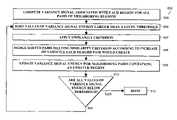
- FIG. 1is a schematic flow diagram depicting steps in the analysis of a sequence of images of tissue according to an illustrative embodiment of the invention.
- FIGS. 2 A and 2 A- 1depict human cervix tissue and show an area of which a sequence of images are to be obtained according to an illustrative embodiment of the invention.
- FIG. 2Bdepicts the characterization of a discrete signal from a sequence of images of tissue according to an illustrative embodiment of the invention.
- FIGS. 3A and 3Bshow a series of graphs depicting mean signal intensity of a region as a function of time, as determined from a sequence of images according to an illustrative embodiment of the invention.
- FIG. 4Adepicts a “maximum” RGB image representation used in preprocessing a sequence of images of tissue according to an illustrative embodiment of the invention.
- FIG. 4Bdepicts the image representation of FIG. 4A after applying a manual mask, used in preprocessing a sequence of images of tissue according to an illustrative embodiment of the invention.
- FIG. 4Cdepicts the image representation of FIG. 4B after accounting for glare, used in preprocessing a sequence of images of tissue according to an illustrative embodiment of the invention.
- FIG. 4Ddepicts the image representation of FIG. 4C after accounting for chromatic artifacts, used in preprocessing a sequence of images of tissue according to an illustrative embodiment of the invention.
- FIG. 5shows a graph illustrating the determination of a measure of similarity of time series of mean signal intensity for each of two regions according to an illustrative embodiment of the invention.
- FIG. 6is a schematic flow diagram depicting a region merging approach of segmentation according to an illustrative embodiment of the invention.
- FIG. 7Arepresents a segmentation mask produced using a region merging approach according to an illustrative embodiment of the invention.
- FIG. 7Bshows a graph depicting mean signal intensities of segmented regions represented in FIG. 7A as functions of time according to an illustrative embodiment of the invention.
- FIG. 8is a schematic flow diagram depicting a robust region merging approach of segmentation according to an illustrative embodiment of the invention.
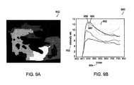
- FIG. 9Arepresents a segmentation mask produced using a robust region merging approach according to an illustrative embodiment of the invention.
- FIG. 9Bshows a graph depicting mean variance signals of segmented regions represented in FIG. 9A as functions of time according to an illustrative embodiment of the invention.
- FIG. 10is a schematic flow diagram depicting a clustering approach of segmentation according to an illustrative embodiment of the invention.
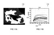
- FIG. 11Arepresents a segmentation mask produced using a clustering approach according to an illustrative embodiment of the invention.
- FIG. 11Bshows a graph depicting mean signal intensities of segmented regions represented in FIG. 11A as functions of time according to an illustrative embodiment of the invention.
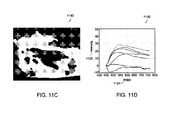
- FIG. 11Crepresents a segmentation mask produced using a clustering approach according to an illustrative embodiment of the invention.
- FIG. 11Dshows a graph depicting mean signal intensities of segmented regions represented in FIG. 11C as functions of time according to an illustrative embodiment of the invention.
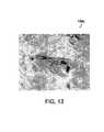
- FIG. 12is a schematic flow diagram depicting a watershed approach of segmentation according to an illustrative embodiment of the invention.
- FIG. 13represents a gradient image used in a watershed approach of segmentation according to an illustrative embodiment of the invention.
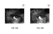
- FIG. 14Arepresents a segmentation mask produced using a watershed approach according to an illustrative embodiment of the invention.
- FIG. 14Brepresents a segmentation mask produced using a watershed approach according to an illustrative embodiment of the invention.
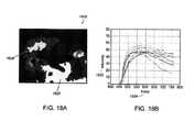
- FIG. 15Arepresents a seed region superimposed on a reference image from a sequence of images, used in a region growing approach of segmentation according to an illustrative embodiment of the invention.
- FIG. 15Brepresents the completed growth of the “seed region” of FIG. 15A using a region growing approach according to an illustrative embodiment of the invention.
- FIG. 16Arepresents a segmentation mask produced using a combined clustering approach and robust region merging approach according to an illustrative embodiment of the invention.
- FIG. 16Bshows a graph depicting mean signal intensities of segmented regions represented in FIG. 16A as functions of time according to an illustrative embodiment of the invention.
- FIG. 17Arepresents a segmentation mask produced using a combined clustering approach and watershed technique according to an illustrative embodiment of the invention.
- FIG. 17Bshows a graph depicting mean signal intensities of segmented regions represented in FIG. 17A as functions of time according to an illustrative embodiment of the invention.
- FIG. 18Arepresents a segmentation mask produced using a two-part clustering approach according to an illustrative embodiment of the invention.
- FIG. 18Bshows a graph depicting mean signal intensities of segmented regions represented in FIG. 18A as functions of time according to an illustrative embodiment of the invention.
- FIG. 19depicts the human cervix tissue of FIG. 2A with an overlay of manual doctor annotations made after viewing an image sequence.
- FIG. 20Ais a representation of a segmentation mask produced using a combined clustering approach and robust region merging approach with a correspondingly-aligned overlay of the manual doctor annotations of FIG. 19 , according to an embodiment of the invention.
- FIG. 20Bis a representation of a segmentation mask produced using a combined clustering approach and morphological technique with a correspondingly-aligned overlay of the manual doctor annotations of FIG. 19 , according to an embodiment of the invention.
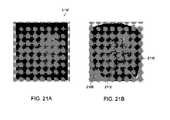
- FIG. 21Adepicts a reference image of cervical tissue of a patient from a sequence of images obtained during an acetowhitening test according to an illustrative embodiment of the invention.
- FIG. 21Bdepicts an image from the sequence of FIG. 21A after applying a manual mask, accounting for glare, and accounting for chromatic artifacts according to an illustrative embodiment of the invention.
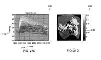
- FIG. 21Cshows a graph depicting mean signal intensities of segmented regions for the sequence of FIG. 21A determined using a clustering segmentation approach according to an illustrative embodiment of the invention.
- FIG. 21Drepresents a map of regions of tissue as segmented in FIG. 21C classified as either high grade disease tissue or not high grade disease tissue using a classification algorithm according to an illustrative embodiment of the invention.
- the inventionprovides methods for image segmentation across a plurality of images. Segmentation across a plurality of images provides a much more robust analysis than segmentation in a single image. Segmentation across multiple images according to the invention allows incorporation of a temporal element (e.g., the change of tissue over time in a sequence of images) in optics-based disease diagnosis.
- the inventionprovides means to analyze changes in tissue over time in response to a treatment. It also provides the ability to increase the resolution of segmented imaging by increasing the number of images over time. This allows an additional dimension to image-based tissue analysis, which leads to increase sensitivity and specificity of analysis. The following is a detailed description of a preferred embodiment of the invention.
- the schematic flow diagram 100 of FIG. 1depicts steps in the analysis of a sequence of images of tissue according to an illustrative embodiment of the invention.
- FIG. 1also serves as a general outline of the contents of this description.
- the stepsinclude obtaining a sequence of images of the tissue 102 , preprocessing the images 104 , determining a measure of similarity between regions in each of the images 108 , segmenting the images 110 , relating the images 112 , and finally, determining a tissue characteristic 114 .
- the stepsmay be preceded by application of a chemical agent onto the tissue, for example. In other embodiments, a chemical agent is applied during the performance of the steps of the schematic flow diagram 100 FIG. 1 .
- the segmentation techniques of the inventive embodiments discussed hereininclude region merging, robust region merging, clustering, watershed, and region growing techniques, as well as combinations of these techniques.
- FIGS. 2A , 2 A- 1 , and 2 Brelate to step 102 of FIG. 1 , obtaining a sequence of images of the tissue.
- FIG. 2Adepicts a full-frame image 202 of a human cervix after application of acetic acid, at the start of an aceto-whitening test.
- the inset image 204depicts an area of interest to be analyzed herein using embodiment methods of the invention. This area of interest may be determined by a technician or may be determined in a semi-automated fashion using a multi-step segmentation approach such as one of those discussed herein below.
- FIG. 2Bdepicts the characterization 206 of a discrete signal w(i,j;t) from a sequence of images of tissue according to an illustrative embodiment of the invention.
- the signalcould be any type of image signal of interest known in the art.
- the signalis an intensity signal of an image.
- images of an area of interestare taken at N time steps ⁇ t 0 , t 1 , . . . , t N-1 ⁇ .
- time t 0corresponds to the moment of application of a chemical agent to the tissue, for instance
- time t N ⁇ 1corresponds to the end of the test.
- n N-1 ⁇be the image and time domains, respectively, where r is the number of rows and c is the number of columns.
- r ⁇ c discrete signals w(i,j;t)may be constructed describing the evolution of some optically-detectable phenomena, such as aceto-whitening, with time.
- the “whiteness”may be computed from RGB data of the images.
- the signal w(i,j;t)is defined in any of a multiplicity of other ways.
- the characterization 206 of FIG. 2Bshows that the intensity signal w(i,j;t) has a value corresponding to each discrete location (i,j) in each of the images taken at N discrete time steps.
- a location (i,j) in an imagecorresponds to a single pixel.
- the whitening signalsare background subtracted.
- each of the signals corresponding to a given location at a particular time stepare transformed by subtracting the initial intensity signal at that location as shown in Equation (2): w(i,j;n) w(i,j;n) ⁇ w(i,j;n 0 ), ⁇ n ⁇ .
- Noise, glare, and sometimes chromatic artifactsmay corrupt images in a sequence.
- Signal noise due to misaligned image pairs and local deformations of the tissuemay be taken into account as well.
- Alignment functions and image restoration techniquesoften do not adequately reduce this type of noise. Therefore, it may be necessary to apply temporal and spatial filters.
- FIGS. 3A and 3Brelate to part of step 104 of FIG. 1 , preprocessing the images.
- FIGS. 3A and 3Bshow a series of graphs depicting mean signal intensity 304 of a pixel as a function of time 306 , as determined from a sequence of images according to an illustrative embodiment of the invention.
- the graphsdepict application of a morphological filter, application of a diffusion filter, modification of intensity data to account for background intensity, and normalization of intensity data, according to an illustrative embodiment of the invention.
- a first filteris applied to the time axis, individually for each pixel.
- the imagesare then spatially filtered.
- Graph 302 of FIG. 3Adepicts the application of both a temporal filter and a spatial filter at a representative pixel.
- the original datais connected by a series of line segments 308 . It is evident from graph 302 that noise makes the signal choppy and adversely affects further analysis if not removed.
- the structuring elementhas a half circle shape.
- the temporally-filtered datais connected by a series of line segments 310 in the graph 302 of FIG. 3 A. The noise is decreased from the series 308 to the series 310 .
- the imagesare then spatially filtered, for example, with either an isotropic or a Gaussian filter.
- a diffusion equation implemented by an illustrative isotropic filtermay be expressed as Equation (4):
- Equation (4)The iterative filter of Equation (4) is much faster than a Gaussian filter, since the iterative filter allows for increasing smoothness by performing successive iterations.
- the Gaussian filterrequires re-applying a more complex filter to the original image for increasing degrees of filtration.
- the methods of the inventionperform two iterations. However, in other embodiments, the method performs one iteration or three or more iterations.
- the spatially-filtered data for a representative pixelis connected by a series of line segments 312 in graph 302 of FIG. 3A .
- the noiseis decreased from series 310 to series 312 .
- Graph 314 of FIG. 3Bshows the application of Equation (2), background subtracting the intensity signal 304 .
- Graph 318 of FIG. 3Bshows the intensity signal data following normalization 320 .
- normalizationincludes division of values of the intensity signal 304 by a reference value, such as the maximum intensity signal over the sequence of images. Glare and chromatic artifacts can affect selection of the maximum intensity signal; thus, in an illustrative embodiment, normalization is performed subsequent to correcting for glare and chromatic artifacts.
- the inventionmasks glare and chromatic artifacts from images prior to normalization.
- glaremay have a negative impact, since glare is visually similar to the tissue whitening that is the object of the analysis.
- Chromatic artifactsmay have a more limited impact on the intensity of pixels and may be removed with the temporal and spatial filters described above.
- Thresholdingmay be used to mask out glare and chromatic artifacts.
- thresholdingis performed in the L*u*v* color space.
- the inventionalso employs a correlate for hue, expressed as in Equation (5):
- Equation (6)a ⁇ ⁇ tan ⁇ ( v * u * ) ( 5 ) Since the hue h* is a periodic function, the illustrative methods of the invention rotate the u*-v* plane such that the typical reddish color of the cervix correlates to higher values of h*. This makes it possible to work with a single threshold for chromatic artifacts.
- the rotationis given by Equation (6):
- FIGS. 4A and 4Brelate to part of step 104 of FIG. 1 , preprocessing the images.
- FIG. 4Adepicts a “maximum” RGB image representation 402 used in preprocessing a sequence of images of tissue according to an illustrative embodiment of the invention.
- the maximum RGB imageis computed by taking for each pixel the maximum RGB values in the whole sequence of images.
- FIG. 4Bdepicts the image representation of FIG. 4A after applying a manual mask, used in preprocessing a sequence of images of tissue according to an illustrative embodiment of the invention.
- the methodapplies the manual mask in addition to the masks for glare and chromatic effects in order to account for obstructions such as hair, foam from the chemical agent, or other obstruction, and/or to narrow analysis to an area of interest.
- Area 406 of the frame 404 of FIG. 4Bhas been manually masked in accord with the methods of the embodiment.
- FIG. 4Cwhich depicts the image representation of FIG. 4B after accounting for glare, is used in preprocessing a sequence of images of tissue according to an illustrative embodiment of the invention. Note that the areas 408 , 410 , 412 , 414 , 416 , and 418 of the frame 405 of FIG. 4C have been masked for glare using Equation (7).
- FIG. 4Dwhich depicts the image representation of FIG. 4C after accounting for chromatic artifacts, is used in preprocessing a sequence of images of tissue according to an illustrative embodiment of the invention.
- the areas 420 and 422 of the frame 407 of FIG. 4Dhave been masked for chromatic artifacts using Equation (8).
- illustrative methods of the inventionpre-segment the image plane into grains.
- the mean grain surfaceis about 30 pixels. However, in other embodiments, it is between about a few pixels and about a few hundred pixels.
- the segmentation methodscan be applied starting at either the pixel level or the grain level.
- One way to “pre-segment” the image plane into grainsis to segment each of the images in the sequence using a watershed transform.
- One goal of the watershed techniqueis to simplify a gray-level image by viewing it as a three-dimensional surface and by progressively “flooding” the surface from below through “holes” in the surface.
- the third dimensionis the gradient of an intensity signal over the image plane (further discussed herein below).
- a “hole”is located at each minimum of the surface, and areas are progressively flooded as the “water level” reaches each minimum.
- the flooded minimaare called catchment basins, and the borders between neighboring catchment basins are called watersheds.
- the catchment basinsdetermine the pre-segmented image.
- Image segmentation with the watershed transformis preferably performed on the image gradient. If the watershed transform is performed on the image itself, and not the gradient, the watershed transform may obliterate important distinctions in the images. Determination of a gradient image is discussed herein below.
- Segmentationis a process by which an image is split into different regions according to one or more pre-defined criteria.
- segmentation methodsare performed using information from an entire sequence of images, not just from one image at a time. The area depicted in the sequence of images is split into regions based on a measure of similarity of the detected changes those regions undergo throughout the sequence.
- Segmentationis useful in the analysis of a sequence of images such as in aceto-whitening cervical testing.
- segmentationis needed. Often, filtering and masking procedures are insufficient to adequately relate regions of an image based on the similarity of the signals those regions produce over a sequence of images. Therefore, the illustrative methods of the invention average time-series data over regions made up of pixels whose signals display similar behavior over time.
- regions of an imageare segmented based at least in part upon a measure of similarity of the detected changes those regions undergo. Since a measure of similarity between regions depends on the way regions are defined, and since regions are defined based upon criteria involving the measure of similarity, the illustrative embodiment of the invention employs an iterative process for segmentation of an area into regions. In some embodiments, segmentation begins by assuming each pixel or each grain (as determined above) represents a region. These individual pixels or grains are then grouped into regions according to criteria defined by the segmentation method. These regions are then merged together to form new, larger regions, again according to criteria defined by the segmentation method.
- a problem that arises when processing raw image datais its high dimension.
- a typical whitening signal for a single pixeldescribed by, for example, a sixty-or-more-dimensional vector, it is often necessary to reduce data dimensionality prior to processing.
- the inventionobtains a scalar that quantifies a leading characteristic of two vectors. More particularly, illustrative methods of the invention take the N-dimensional inner (dot) product of two vectors corresponding to two pixel coordinates. A fitting function based on this dot product is shown in Equation (9). This fitting function quantifies the similarity between the signals at two locations.
- FIG. 5relates to step 108 of FIG. 1 , determining a measure of similarity between regions in each of a series of images.
- FIG. 5shows a graph 502 illustrating the determination of a measure of similarity of a time series of mean signal intensity 504 for each of two regions k and l according to an illustrative embodiment of the invention.
- FIG. 5represents one step in an illustrative segmentation method in which the similarity between the time-series signals of two neighboring regions is compared against criteria to determine whether those regions should be merged together.
- the type of measure of similarity chosenmay vary depending on the segmentation method employed.
- Curve 506 in FIG. 5represents the mean signal intensity 504 of region k in each of a sequence of images and is graphed versus time 505 .
- Mean signal intensity 504 of region kis expressed as in Equation (10):
- w ⁇ ( k ; t )1 N k ⁇ ⁇ ( i , j ) ⁇ ?? k ⁇ ⁇ w ⁇ ( i , j ; t ) , ( 10 ) where k ⁇ 2 is the set of all pixels that belong to the k th region and N k is the size of k .
- Curve 508 of FIG. 5represents the mean signal intensity 504 of region l and is graphed versus time 505 .
- Mean signal intensity 504 of region lis expressed as in Equation (10), replacing “k” with “l” in appropriate locations.
- the shaded area 510 of FIG. 5represents dissimilarity between mean signals over region k and region l.
- the chosen measure of similarity, ⁇ klalso referred to herein as the fitting function, between regions k and l may depend on the segmentation method employed. For the region merging segmentation technique, discussed in more detail below, as well as for other segmentation techniques, the measure of similarity used is shown in Equation (11):
- ⁇ kl⁇ w ⁇ ( k ; t ) , w ⁇ ( l ; t ) ⁇ max ⁇ ( ⁇ ⁇ ( k ) , ⁇ ⁇ ( l ) ) , ( 11 )
- the numeratorrepresents the N-dimensional dot product of the background-subtracted mean signal intensities 504 of region k and region l; the denominator represents the greater of the energies of the signals corresponding to regions k and l, ⁇ (k) and ⁇ (l); and ⁇ 1 ⁇ kl ⁇ 1.
- the numerator of Equation (11)is normalized by the higher signal energy and not by the square root of the product of both energies.
- Equation (9)the fitting function defined by Equation (9) can be used to obtain a gradient image representing the variation of whitening values in x-y space.
- the gradient of an image made up of intensity signalsis the approximation of the amplitude of the local gradient of signal intensity at every pixel location.
- the watershed transformis then applied to the gradient image. This may be done when pre-segmenting images into “grains” as discussed above, as well as when performing the hierarchical watershed segmentation approach and combined method segmentation approaches discussed below.
- ⁇ ⁇ ⁇ ( i , j ; i 0 , j 0 )⁇ ⁇ 1 - ⁇ ⁇ ( i , j ; i 0 , j 0 ) 1 + ⁇ ⁇ ( i , j ; i 0 , j 0 ) , ( 12 ) where ⁇ ⁇ ⁇ ⁇ ⁇ ( i , j ; i 0 , j 0 ) ⁇ ( - ⁇ , ⁇ ) .
- the fitting valuesinclude information from the entire sequence of images
- a gradient imagewhich includes information from the entire sequence of images, and which, therefore, shows details not visible in all of the images.
- the gradient imagemay be used in the watershed pre-segmentation technique discussed herein above and the hierarchical watershed technique discussed herein below. Had the gradient image been obtained from a single reference image, less detail would be included, and the application of a watershed segmentation method to the gradient image would segment the image plane based on less data. However, by using a gradient image as determined from Equations (14) and (15), the invention enables a watershed segmentation technique to be applied which divides an image plane into regions based on an entire sequence of data, not just a single reference image.
- FIG. 6relates to step 110 of FIG. 1 , segmenting the area represented in a sequence of images into regions based on measures of similarity between regions over the sequence.
- FIG. 6shows a schematic flow diagram 602 depicting a region merging technique of segmentation according to an illustrative embodiment of the invention.
- each grain or pixelis initially a region, and the method merges neighboring according to a predefined criterion in an iterative fashion.
- the criterionis based on a measure of similarity, also called a fitting function.
- the segmentationconverges to the final result when no pair of neighboring regions satisfies the merging criterion.
- aceto-whitening datafor instance, it is desired to merge regions whose whitening data is similar.
- the fitting functionwill therefore quantify the similarity over the sequence between two signals corresponding to two neighboring regions.
- the segmentationbegins at step 604 of FIG. 6 , computing the fitting function to obtain “fitting values” for all pairs of neighboring regions.
- thisis the measure of similarity provided by Equation (11), where mean signal intensity of a region k is defined by Equation (10).
- This fitting functionis equivalent to the minimum normalized Euclidean distance, ⁇ 2 kl , between the mean signal intensities of regions k and l shown in Equation (16):
- ⁇ kl 2
- L 2 2 max ⁇ ( ⁇ ⁇ ( k ) , ⁇ ⁇ ( l ) )2 ⁇ ( 1 2 ⁇ ( 1 + min ⁇ ( ⁇ ⁇ ( k ) , ⁇ ⁇ ( l ) ) max ⁇ ( ⁇ ⁇ ( k ) , ⁇ ⁇ ( l ) ) ) - ⁇ w ⁇ ( k ; t ) , w ⁇ ( l ; t ) ⁇ max ⁇ ( ⁇ ⁇ ( k ) , ⁇ ⁇ ( l ) ) ) .
- Equation (16)This notation reveals the effect of normalizing using the higher energy of the two signals instead of normalizing each signal by its L 2 norm.
- Equation (16) or Equation (11)applies an additional “penalty” when both signals have different energies, and therefore, fitting values are below 1.0 when the scaled versions of the two signals are the same, but their absolute values are different.
- step 606 of FIG. 6the fitting values (measures of similarity) corresponding to pairs of neighboring regions that are larger than a given threshold are sorted from greatest to least.
- step 608sorted pairs are merged according to best fit, keeping in mind that each region can only be merged once during one iteration. For instance, if neighboring regions k and l have a fitting value of 0.80 and neighboring regions k and m have a fitting value of 0.79, regions k and l are merged together, not k and m. However, region m may be merged with another of its neighboring regions during this iteration, depending on the fitting values computed.
- step 609the method recalculates fitting values for all pairs of neighboring regions containing an updated (newly merged) region.
- Fitting valuesare not recalculated for pairs of neighboring regions whose regions are unchanged.
- step 610 of FIG. 6it is determined whether the fitting values of all pairs of neighboring regions are below a given threshold.
- the fitting functionis a measure of similarity between regions; thus, the higher the threshold, the more similar regions have to be in order to be merged, resulting in fewer iterations and, therefore, more regions that are ultimately defined. If the fitting values of all the regions are below the given threshold, the merging is complete 612 . If not, the process beginning at step 606 repeats, and fitting values of the pairs of neighboring regions as newly defined are sorted.
- a size ruleis applied that forces each region whose size is below a given value to be merged with its best fitting neighboring region, even though the fitting value is lower than the threshold. In this way, very small regions not larger than a few pixels are avoided.
- segmentation method of FIG. 6is performed, for example, where each pixel has up to four neighbors: above, below, left, and right. However, in other illustrative embodiments, segmentation is performed where each pixel can has up to eight neighbors or more, which includes diagonal pixels. It should also be noted that images in a given sequence may be sub-sampled to reduce computation time. For instance, a sequence of 100 images may be reduced to 50 images by eliminating every other image from the sequence to be segmented.
- FIGS. 7A and 7Billustrate step 112 of FIG. 1 , relating images after segmentation.
- FIG. 7Adepicts a segmentation mask 702 produced using the region merging segmentation technique discussed above for an exemplary aceto-whitening sequence.
- the threshold used in step 610 of FIG. 6 to produce this segmentation mask 702is 0.7.
- Each regionhas a different label, and is represented by a different color in the mask 702 in order to improve the contrast between neighboring regions.
- Other illustrative embodimentsuse other kinds of display techniques known in the art, in order to relate images of the sequence based on segmentation and/or based on the measure of similarity.
- FIG. 7Bshows a graph 750 depicting mean signal intensities 752 of segmented regions represented in FIG. 7A as functions of a time index 754 according to an illustrative embodiment of the invention.
- the color of each data series in FIG. 7Bcorresponds to the same-colored segment depicted in FIG. 7A .
- Thisis one way to visually relate a sequence of images using the results of segmentation. For instance, according to the illustrative embodiment, regions having a high initial rate of increase of signal intensity 752 are identified by observing data series 756 and 758 in FIG. 7B , whose signal intensities 752 increase more quickly than the other data series. The location of the two regions corresponding to these two data series is found in FIG. 7A .
- kinetic rate constantsare derived from each of the data series determined in FIG. 7B , and the regions having data series most closely matching kinetic rate constants of interest are identified.
- one or more data seriesare curve fit to obtain a characterization of the mean signal intensities 752 of each data series as functions of time.
- Mean signal intensitymay have a negative value after background subtraction. This is evident, for example, in the first part of data series 760 of FIG. 7B . In some examples, this is due to the choice of the reference frame for background subtraction. In other examples, it is due to negative intensities corresponding to regions corrupted by glare that is not completely masked from the analysis.
- FIG. 8relates to step 110 of FIG. 1 , segmenting the area represented in a sequence of images into regions based on measures of similarity between regions over the sequence.
- FIG. 8shows a schematic flow diagram 802 depicting a robust region merging approach of segmentation according to an illustrative embodiment of the invention.
- One objective of the robust region merging approachis to take into account the “homogeneity” of data inside the different regions. While the region merging approach outlined in FIG. 6 relies essentially on the mean signal of each region to decide subsequent merging, the robust region merging approach outlined in FIG. 8 controls the maximum variability allowed inside each region. More specifically, the variance signal, ⁇ 2 w (k;t), associated with each region, k, is computed as in Equation (17):
- Segmentation using the illustrative robust region merging approachbegins at step 804 of the schematic flow diagram 802 of FIG. 8 .
- the variance signal, ⁇ 2 w (k;t), of Equation (17)is computed for each region k.
- variance signal energyor the energy of the standard deviation signal as shown in Equation (18)
- the values of variance signal energy that are larger than a given thresholdare sorted. This determines which regions can be merged, but not in which order the regions may be merged.
- the sorted pairsare merged according to the increase in variance each merged pair would create, ⁇ ⁇ (k,l), given by Equation (19):
- ⁇ ⁇ ⁇ ( k , l )⁇ t ⁇ T ⁇ ( ⁇ w 2 ⁇ ( k ⁇ l ; t ) - 1 2 [ ⁇ w 2 ⁇ ( k ; t ) + ⁇ w 2 ⁇ ( l ; t ) ] ) , ( 19 )
- k and lrepresent two neighboring regions to be merged.
- the methods of the inventionapply an additional criterion as shown in step 807 of FIG. 8 prior to merging sorted pairs in step 808 .
- step 807fitting values corresponding to the pairs of neighboring regions are checked against a threshold. The fitting values are determined as shown in Equation (11), used in the region-merging approach.
- a candidate pair of regionsare not merged if its fitting value is below the threshold (e.g., if the two regions are too dissimilar).
- ⁇ kl0.7. This value is low enough not to become the main criterion, yet the value is high enough to avoid the merging of regions with very different signals.
- other ⁇ kl valuesmay be used without deviating from the scope of the invention.
- step 809 of FIG. 8values of the variance signal are recalculated for pairs of neighboring regions containing an updated (newly-merged) region. According to an embodiment of the invention, variance signal values are not recalculated for pairs of neighboring regions whose regions are unchanged.
- FIGS. 9A and 9Billustrate step 112 of FIG. 1 , relating images after segmentation.
- FIG. 9Adepicts a segmentation mask 902 produced using the robust region merging segmentation technique discussed above for an exemplary aceto-whitening sequence.
- the variance threshold used in step 810 of FIG. 8 to produce the segmentation mask 902is 70.
- Each regionhas a different label, and is represented by a different color in the mask 902 to improve the contrast between neighboring regions.
- Other display techniquesmay be used to relate images of the sequence based on segmentation and/or based on the measure of similarity.
- FIG. 9Bshows a graph 950 depicting mean signal intensity 952 of segmented regions represented in FIG. 9A as functions of a time index 954 according to an illustrative embodiment of the invention.
- the color of each curve in FIG. 9Bcorresponds to the same-colored segment depicted in FIG. 9A . This is one way to visually relate a sequence of images using the results of segmentation.
- the methodobserves data series 956 , 958 , 960 , and 962 in FIG. 9B , whose signal intensities 952 increase more quickly than the other data series.
- the location of the four regions corresponding to these four data seriesare in FIG. 9A .
- the methodderives kinetic rate constants from each of the data series determined in FIG. 9B , and the regions having data series most closely matching kinetic rate constants of interest are identified.
- the methodcurve fits one or more data series to obtain a characterization of the mean signal intensities 952 of each data series as functions of time.
- FIG. 10relates to step 110 of FIG. 1 , segmenting an area represented in a sequence of images into regions based on measures of similarity between regions over the sequence, according to one embodiment of the invention.
- FIG. 10shows a schematic flow diagram 1002 depicting a segmentation approach based on the clustering of data, or more precisely, a “fuzzy c-means” clustering segmentation approach, used in an embodiment of the invention.
- An objective of this clustering approachis to group pixels into clusters with similar values.
- the methoddoes not merge regions based on their spatial relation to each other. In other words, two non-neighboring regions may be merged, depending on the criterion used.
- v iis the “center” of the i th cluster
- u ik ⁇ [0,1]is called the fuzzy membership of x k to v i , with
- Equation (23)The distance, ⁇ x k ⁇ v j ⁇ , is based on the fitting function given in Equation (11). If it is assumed that similar signals are at a short distance from each other, then Equation (23) results:
- the methodsets the initial value of v i randomly.
- the methodcalculates values of u ik , the fuzzy membership of x k to v i , according to Equation (21).
- the methodupdates values of v i according to Equation (22), using the previously determined value of u ik .
- the algorithmconverges when the relative decrease of the functional J m as defined by Equation (20) is below a predefined threshold, for instance, 0.001.
- an embodiment of the methoddetermines whether the relative decrease of J m is below the threshold. If not, then the process beginning at step 1006 is repeated. If the relative decrease of J m is below the threshold, then the segmentation is completed by labeling each pixel according to its highest fuzzy membership,
- Some embodimentshave more regions than clusters, since pixels belonging to different regions with similar signals can contribute to the same cluster.
- FIGS. 11A and 11Bshow an illustrative embodiment of the method at step 112 of FIG. 1 .
- FIG. 11Adepicts a segmentation mask 1102 produced using the clustering technique discussed above for an exemplary aceto-whitening sequence, according to the embodiment.
- the number of clusters, c, chosen in this embodimentis 3. There are more regions than clusters, since portions of some clusters are non-contiguous.
- the threshold for the relative decrease of J m in step 1010 of FIG. 10is chosen as 0.001 in this embodiment.
- Each clusterhas a different label and is represented by a different color in the mask 1102 .
- Other embodimentsemploy other kinds of display techniques to relate images of the sequence based on segmentation and/or based on the measure of similarity.
- FIG. 11Bshows a graph 1120 depicting mean signal intensities 1122 of segmented regions represented in FIG. 11A as functions of a time index 1124 according to an illustrative embodiment of the invention.
- the color of each data series in FIG. 11Bcorresponds to the same-colored cluster depicted in FIG. 11A .
- the graph 1120 of FIG. 11Bis one way to visually relate a sequence of images using the results of segmentation according to this embodiment.
- the methodidentifies a cluster having a high initial rate of increase of signal intensity 1122 by observing data series 1126 in FIG. 11B , whose signal intensity increases more quickly than the other data series. Regions belonging to the same cluster have data series 1126 of the same color.
- the methodderives kinetic rate constants from each of the data series determined in FIG. 11B , and the regions having data series most closely matching kinetic rate constants of interest are identified.
- the methodcurve fits one or more data series to obtain characterization of the mean signal intensities 1122 of each data series as functions of time.
- FIGS. 11C and 11Dillustrate an embodiment of the method at step 112 of FIG. 1 , relating images after segmentation.
- FIG. 11Cdepicts a segmentation mask 1140 produced using the clustering technique for the exemplary aceto-whitening sequence in FIG. 11A , according to the embodiment.
- the number of clusters, c, chosenis 2. Again, there are more regions than clusters, since portions of the same clusters are non-contiguous.
- the threshold for the relative decrease of J m in step 1010 of FIG. 10is 0.001 for this embodiment.
- FIG. 12relates to step 110 of FIG. 1 , segmenting the area represented in a sequence of images into regions based on measures of similarity between regions over the sequence, according to an illustrative embodiment of the invention.
- morphological techniques of segmentationare continued beyond filtering and pre-segmentation.
- FIG. 12shows a schematic flow diagram 1202 depicting a hierarchical watershed approach of segmentation according to the illustrative embodiment.
- the methodcomputes a gradient image from Equations (14) and (15) according to the embodiment, which incorporates data from the entire sequence of images, as discussed above.
- the methodsegments data based on information from the entire sequence of images, not just one image.
- a watershed transformis applied to this gradient image in step 1206 of FIG. 12 .
- Some embodimentsapply first-in-first-out (FIFO) queues, sorted data, and other techniques to speed the performance of the watershed transform.
- the methodapplies a sigmoidal scaling function to the gradient image, prior to performing the watershed transform to enhance the contrast between whitish and reddish (dark) regions, which is particularly useful when analyzing images of a cervix.
- the catchment basins resulting from application of the watershed transformrepresent the segmented regions in this embodiment.
- FIG. 13shows a gradient image 1302 calculated from Equations (5) and (6) for an exemplary sequence of images, according to an embodiment of the invention.
- the method at step 1208 of FIG. 12constructs a new gradient image using geodesic reconstruction.
- Two different techniques of geodesic reconstruction which embodiments may employinclude erosion and dilation.
- the methoddetermines whether over-segmentation has been reduced sufficiently, according to this embodiment. If so, the segmentation may be considered complete, or one or more additional segmentation techniques may be applied, such as a region merging or robust region merging technique, both of which are discussed above. If over-segmentation has not been reduced sufficiently, the method calculates the watershed transform of the reconstructed gradient image as in step 1206 , and the process is continued.
- Certain embodiment methodsuse the hierarchical watershed to segment larger areas, such as large lesions or the background cervix.
- the number of iterationsis less than about 4 such that regions do not become too large, obscuring real details.
- the methodperforms one iteration of the hierarchical watershed, and continues merging regions using the robust region merging technique.
- FIGS. 14A and 14Bshow an illustrative embodiment of the method at step 112 of FIG. 1 , relating images after segmentation.
- FIG. 14Adepicts a segmentation mask 1402 produced using one iteration of the hierarchical watershed technique discussed above for an exemplary aceto-whitening sequence, according to the embodiment. Each region has a different label, and is represented by a different color in the mask 1402 .
- FIG. 14Bdepicts a segmentation mask 1430 produced using two iterations of the hierarchical watershed technique discussed above for the exemplary aceto-whitening sequence, according to the embodiment.
- the segmentation mask 1430 in FIG. 14Bproduced using two iterations, has fewer regions and is more simplified than the segmentation mask 1402 in FIG. 14A , produced using one iteration.
- a “region growing technique”to performing step 110 of FIG. 1 , segmenting an area represented in a sequence of images into regions based on measures of similarity between regions over the sequence.
- the region growing techniqueis different from the region merging and robust region merging techniques in that one or more initial regions, called seed regions, grow by merging with neighboring regions.
- the region merging, robust region merging, and region growing methodsare each iterative.
- the region merging and region growing techniqueseach use the same fitting function to evaluate the similarity between signals from neighboring regions.
- the usermanually selects seed regions.
- the seed regionsare selected in an automatic fashion. Hard criteria may be used to select areas that are of high interest and/or which behave in a certain way.
- a userselects seed regions based on that user's experience.
- the region growing algorithmthen proceeds by detecting similar regions and adding them to the set of seeds.
- One embodiment of the inventionis a combined technique using the region growing algorithm, starting with a grain image, followed by performing one iteration of the hierarchical watershed technique, and then growing the selected region according to the robust region merging algorithm.
- the segmentation techniques discussed hereinare combined in various ways.
- the methodprocesses and analyzes data from a sequence of images in an aceto-whitening test, for instance, using a coarse-to-fine approach.
- a first segmentationreveals large whitening regions, called background lesions, which are then considered as regions of interest and are masked for additional segmentation.
- a second segmentation step of the embodimentmay outline smaller regions, called foreground lesions. Segmentation steps subsequent to the second step may also be considered.
- the term “lesion”does not necessarily refer to any diagnosed area, but to an area of interest, such as an area displaying a certain whitening characteristic during the sequence. From the final segmentation, regions are selected for diagnosis, preliminary or otherwise; for further analysis; or for biopsy, for example. Additionally, the segmentation information may be combined with manually drawn biopsy locations for which a pathology report may be generated. In one illustrative embodiment, the method still applies the pre-processing procedures discussed herein above before performing the multi-step segmentation techniques.
- FIG. 16Ashows a segmentation mask produced using a combined clustering approach and robust region merging approach for an exemplary aceto-whitening sequence, according to an illustrative embodiment of the invention.
- a robust region merging procedureis applied, as shown in FIG. 8 , to the background lesion, according to the embodiment.
- regions less than 16 pixels largeare removed.
- the resulting segmentationis shown in frame 1602 of FIG. 16A .
- FIG. 16Bshows a graph 1604 depicting mean signal intensity 1606 of segmented regions represented in FIG. 16A as functions of a time index 1608 according to an illustrative embodiment of the invention.
- the color of each curve in FIG. 16Bcorresponds to the same-colored segment depicted in FIG. 16A .
- Regions having a high initial rate of increase of signal intensity 1606include regions 1610 and 1612 , shown in FIG. 16A .
- FIG. 17Arepresents a segmentation mask produced using a combined clustering approach and watershed approach for the exemplary aceto-whitening sequence of FIG. 16A , according to an illustrative embodiment of the invention.
- the methodapplies a hierarchical watershed segmentation procedure, as shown in FIG. 12 .
- the methodcomputes one iteration of the watershed transform, then a region merging technique as per FIG. 6 , using a fitting value threshold of 0.85 in step 610 of FIG. 6 . Regions smaller than 16 pixels are removed. The resulting segmentation is shown in frame 1702 of FIG. 17A .
- FIG. 17Bshows a graph 1720 depicting mean signal intensity 1722 of segmented regions represented in FIG. 17A as functions of a time index 1724 according to an illustrative embodiment of the invention.
- the color of each curve in FIG. 17Bcorresponds to the same-colored segment depicted in FIG. 17A .
- Regions having a high initial rate of increase of signal intensity 1722include regions 1726 and 1728 , shown in FIG. 17A .
- FIG. 18Arepresents a segmentation mask produced using a two-step clustering approach for the exemplary aceto-whitening sequence of FIG. 16A , according to an illustrative embodiment of the invention.
- the methodapplies a second clustering procedure, as shown in FIG. 10 , to the background lesion.
- FIG. 18Bshows a graph 1820 depicting mean signal intensity 1822 of segmented regions represented in FIG. 18A as functions of a time index 1824 according to an illustrative embodiment of the invention.
- the color of each curve in FIG. 18Bcorresponds to the same-colored cluster depicted in FIG. 18A .
- Regions having a high initial rate of increase of signal intensity 1822include regions 1828 and 1826 , shown in FIG. 18A .
- FIG. 19depicts the human cervix tissue of FIG. 2A with an overlay of manual doctor annotations made after viewing the exemplary aceto-whitening image sequence discussed herein above. Based on her viewing of the sequence and on her experience with the aceto-whitening procedure, the doctor annotated regions with suspicion of pathology 1904 , 1906 , 1908 , 1910 , and 1912 . The doctor did not examine results of any segmentation analysis prior to making the annotations. Regions 1910 and 1912 were singled out by the doctor as regions with the highest suspicion of pathology.
- FIG. 20Ais a representation of a segmentation mask produced using a combined clustering approach and robust region merging approach as discussed above and as shown in FIG. 16A , according to an illustrative embodiment of the invention.
- the segmentation mask in FIG. 20Ais shown with a correspondingly-aligned overlay of the manual doctor annotations of FIG. 19 .
- FIG. 20Bis a representation of a segmentation mask produced using a combined clustering approach and watershed technique as discussed above and shown in FIG. 18A .
- the segmentation mask in FIG. 20Bis shown with a correspondingly-aligned overlay of the manual doctor annotations of FIG. 19 , according to an embodiment of the invention.
- Areas 1912 and 1910 in FIGS. 20A and 20Bcorrespond to the doctor's annotations of areas of high suspicion of pathology.
- these areas ( 1912 and 1910 )correspond to regions of rapid, intense whitening.
- areas of rapid, intense whiteningcorrespond to areas of suspicion of pathology.
- the techniques discussed hereinprovide a method of determining a tissue characteristic, namely, the presence or absence of a suspicion of pathology. Certain embodiments of the invention use the techniques in addition to a doctor's analysis or in place of a doctor's analysis. Certain embodiments use combinations of the methods described herein to produce similar results.
- Some embodiments of the invention for applications other than the analysis of acetowhitening tests of cervical tissuealso use various inventive analysis techniques as described herein.
- a practitionermay customize elements of an analysis technique disclosed herein, based on the attributes of her particular application, according to embodiments of the invention. For instance, the practitioner may choose among the segmentation techniques disclosed herein, depending on the application for which she intends to practice embodiments of the inventive methods.
- itis possible to visually capture all the frames of a sequence at once and relate regions according to their signals over a period of time.
- Certain embodiments of the invention methodsanalyze more complex behavior. Some embodiments segment the image plane of a sequence of images, then feature-extract the resulting mean intensity signals to characterize the signals of each segmented region. Examples of feature extraction procedures include any number of curve fitting techniques or functional analysis techniques used to mathematically and/or statistically describe characteristics of one or more data series. In some embodiments, these features are then used in a manual, automated, or semi-automated method for the classification of tissue.
- the methodclassifies a region of cervical tissue either as “high grade disease” tissue, which includes Cervical Intraepithelial Neoplasia II/III (CIN II/III), or as “not high grade disease” tissue, which includes normal squamous (NED—no evidence of disease), metaplasia, and CIN I tissue.
- the classification for a segmented regionmay be within a predicted degree of certainty using features extracted from the mean signal intensity curve corresponding to the region. In one embodiment, this classification is performed for each segmented region in an image plane to produce a map of regions of tissue classified as high grade disease tissue.
- Other embodimentsmake more specific classifications and distinctions between tissue characteristics, such as distinction between NED, metaplasia, and CIN I tissue.
- FIG. 21A , FIG. 21B , FIG. 21C , and FIG. 21Ddepict steps in the classification of regions of tissue in a sequence of images obtained during an acetowhitening procedure performed on a patient with high grade disease according to an illustrative embodiment of the invention.
- FIG. 21Adepicts a reference image 2102 of cervical tissue of the patient from a sequence of images obtained during the acetowhitening test.
- FIG. 21Bis a representation 2106 of the reference image 2102 of FIG. 21A after applying a manual mask, accounting for glare, and accounting for chromatic artifacts as discussed herein according to an illustrative embodiment of the invention.
- areassuch as areas 2110 and 2112 of FIG.
- FIG. 21Cshows a graph 2120 depicting mean signal intensities 2122 of segmented regions for the sequence of FIG. 21A as functions of a time index 2124 and as determined using the clustering segmentation approach depicted in the schematic flow diagram 1002 of FIG. 10 and as discussed herein according to an illustrative embodiment of the invention.
- an embodiment of the inventionextracted specific features from each of the mean signal intensity data series depicted in the graph 2120 of FIG. 21C , and used these features in a classification algorithm.
- a classification algorithmwas designed using results of a clinical study.
- mean signal intensity curveswere determined using sequences of images from acetowhitening tests performed on over 200 patients.
- the classification algorithmmay be updated according to an embodiment of the invention upon conducting further or different clinical testing.
- the present algorithmwas based upon two feature parameters extracted from each of certain mean signal intensity data series corresponding to segmented regions of the image sequences for which biopsies were performed. These two feature parameters are as follows:
- FIG. 21Drepresents a map 2130 of regions of tissue as segmented in FIG. 21C classified as either high grade disease tissue or not high grade disease tissue using the classification algorithm of Equation (24).
- This embodimentdetermined this classification for each of the segmented regions by calculating X and Y for each region and determining whether the point (X,Y) falls below the line of Equation (24), in which case the region was classified as high grade disease, or whether the point (X,Y) falls above the line of Equation (24), in which case the region was classified as not high grade disease.
- the embodimentdraws further distinction depending on how far above or below the line of Equation (24) the point (X,Y) falls.
- 21Dindicates segmented regions of high grade disease as red, orange, and yellow, and regions not classifiable as high grade disease as blue.
- the index 2132reflects how far the point (X,Y) of a given segment falls below the line of Equation (24).
- Other embodimentsinclude those employing other segmentation techniques as described herein.
- Still other embodimentsinclude those employing different classification algorithms, including those using feature parameters other than X and Y, extracted from mean signal data series corresponding to segmented regions.
Landscapes
- Engineering & Computer Science (AREA)
- Physics & Mathematics (AREA)
- General Physics & Mathematics (AREA)
- Life Sciences & Earth Sciences (AREA)
- Theoretical Computer Science (AREA)
- Health & Medical Sciences (AREA)
- Computer Vision & Pattern Recognition (AREA)
- Molecular Biology (AREA)
- Biomedical Technology (AREA)
- General Health & Medical Sciences (AREA)
- Medical Informatics (AREA)
- Biophysics (AREA)
- Pathology (AREA)
- Heart & Thoracic Surgery (AREA)
- Multimedia (AREA)
- Surgery (AREA)
- Animal Behavior & Ethology (AREA)
- Public Health (AREA)
- Veterinary Medicine (AREA)
- Image Analysis (AREA)
- Image Processing (AREA)
Abstract
Description


I=0.299R+0.587G+0.114B. (1)
w(i,j;n)


w(t)⊙b=½[(w∘b)•b+(w•b)∘b], (3)
where b is the structuring element, ∘ is the opening operator, and ◯ is the closing operator. According to the illustrative embodiment, the structuring element has a half circle shape. The temporally-filtered data is connected by a series of
where ∇ is the gradient operator, Δ is the Laplacian operator, and τ is the diffusion time (distinguished from the time component of the whitening signal itself). An isotropic filter is iterative, while a Gaussian filter is an infinite impulse response (IIR) filter. The iterative filter of Equation (4) is much faster than a Gaussian filter, since the iterative filter allows for increasing smoothness by performing successive iterations. The Gaussian filter requires re-applying a more complex filter to the original image for increasing degrees of filtration. According to the illustrative embodiment, the methods of the invention perform two iterations. However, in other embodiments, the method performs one iteration or three or more iterations. The spatially-filtered data for a representative pixel is connected by a series of
Since the hue h* is a periodic function, the illustrative methods of the invention rotate the u*-v* plane such that the typical reddish color of the cervix correlates to higher values of h*. This makes it possible to work with a single threshold for chromatic artifacts. The rotation is given by Equation (6):
The masks for glare and chromatic artifacts are then respectively obtained using Equations (7) and (8):
maskglare=L*>90 (7)
maskhue=h*<π/5, (8)
where L*ε[0,100] and h*ε[0,2π]. According to the illustrative embodiment, the masks are eroded to create a safety margin, such that they are slightly larger than the corrupted areas.
where x1and x2are two pixel coordinates, and Ω(x1)=<w(x1;t),w(x1;t)>is the energy of the signal at location x1.
where


where the numerator represents the N-dimensional dot product of the background-subtracted
The norm of the gradient vector is then calculated from the approximations of Equations (14) and (15).
This notation reveals the effect of normalizing using the higher energy of the two signals instead of normalizing each signal by its L2norm. The method using Equation (16) or Equation (11) applies an additional “penalty” when both signals have different energies, and therefore, fitting values are below 1.0 when the scaled versions of the two signals are the same, but their absolute values are different.
where w(k;t) is mean signal intensity of region k as expressed in Equation (10). The merging criterion is then the energy of the standard deviation signal, computed as in Equation (18):
where k and l represent two neighboring regions to be merged. Thus, if a region can merge with more than one of its neighbors, it merges with the one that increases less the variance shown in Equation (19). Another neighbor may merge with the region in the next iteration, given that it still meets the fitting criterion with the updated region.


where viis the “center” of the ithcluster, uikε[0,1] is called the fuzzy membership of xkto vi, with
and mε[1,∞] is a weighting exponent. The inventors have used m=2 in exemplary embodiments. The distance ∥•∥ is any inner product induced norm on
where φkiis given by Equation (11).
Some embodiments have more regions than clusters, since pixels belonging to different regions with similar signals can contribute to the same cluster.
- 1. X is the slope of a curve (here, a polynomial curve) fitted to the mean signal intensity data series of a segmented region at the time corresponding to 235 seconds after application of the acetic acid (M235); and
- 2. Y is the slope of the polynomial curve at the time corresponding to an intensity that is −16 dB from the maximum intensity (about 45% of the maximum mean signal intensity) on the decaying side of the polynomial curve (−16 dB slope).
The choice of the feature parameters X and Y above was made by conducting a Discrimination Function (DF) analysis of the data sets from the clinical study. A wide range of candidate feature parameters, including X and Y, were tested. X and Y provided a classification algorithm having the best accuracy.
Y=−0.9282X−0.1348. (24)
Varying the classification model parameters by as much as 10% yields very similar model outcomes, suggesting the model features are highly stable.
Claims (34)
Priority Applications (5)
| Application Number | Priority Date | Filing Date | Title |
|---|---|---|---|
| US10/099,881US7260248B2 (en) | 1999-12-15 | 2002-03-15 | Image processing using measures of similarity |
| EP03706024AEP1476076A1 (en) | 2002-01-31 | 2003-01-31 | Image processing using measures of similarity |
| AU2003207787AAU2003207787A2 (en) | 2002-01-31 | 2003-01-31 | Image processing using measures of similarity |
| PCT/US2003/003007WO2003063706A1 (en) | 2002-01-31 | 2003-01-31 | Image processing using measures of similarity |
| CA002474417ACA2474417A1 (en) | 2002-01-31 | 2003-01-31 | Image processing using measures of similarity |
Applications Claiming Priority (5)
| Application Number | Priority Date | Filing Date | Title |
|---|---|---|---|
| US17097299P | 1999-12-15 | 1999-12-15 | |
| US09/738,614US6902935B2 (en) | 1999-12-15 | 2000-12-15 | Methods of monitoring effects of chemical agents on a sample |
| US35397802P | 2002-01-31 | 2002-01-31 | |
| US10/068,133US20020127735A1 (en) | 1999-12-15 | 2002-02-05 | Methods of monitoring effects of chemical agents on a sample |
| US10/099,881US7260248B2 (en) | 1999-12-15 | 2002-03-15 | Image processing using measures of similarity |
Related Parent Applications (1)
| Application Number | Title | Priority Date | Filing Date |
|---|---|---|---|
| US10/068,133Continuation-In-PartUS20020127735A1 (en) | 1999-12-15 | 2002-02-05 | Methods of monitoring effects of chemical agents on a sample |
Publications (2)
| Publication Number | Publication Date |
|---|---|
| US20030144585A1 US20030144585A1 (en) | 2003-07-31 |
| US7260248B2true US7260248B2 (en) | 2007-08-21 |
Family
ID=27616078
Family Applications (1)
| Application Number | Title | Priority Date | Filing Date |
|---|---|---|---|
| US10/099,881Expired - Fee RelatedUS7260248B2 (en) | 1999-12-15 | 2002-03-15 | Image processing using measures of similarity |
Country Status (5)
| Country | Link |
|---|---|
| US (1) | US7260248B2 (en) |
| EP (1) | EP1476076A1 (en) |
| AU (1) | AU2003207787A2 (en) |
| CA (1) | CA2474417A1 (en) |
| WO (1) | WO2003063706A1 (en) |
Cited By (24)
| Publication number | Priority date | Publication date | Assignee | Title |
|---|---|---|---|---|
| US20040047498A1 (en)* | 2000-11-22 | 2004-03-11 | Miguel Mulet-Parada | Detection of features in images |
| US20060061595A1 (en)* | 2002-05-31 | 2006-03-23 | Goede Patricia A | System and method for visual annotation and knowledge representation |
| US20060270912A1 (en)* | 2003-03-27 | 2006-11-30 | Koninklijke Philips Electronics N.V. | Medical imaging system and a method for segmenting an object of interest |
| US20070167788A1 (en)* | 2005-09-22 | 2007-07-19 | Andreas Hartlep | Brain tissue classification |
| US20070237378A1 (en)* | 2005-07-08 | 2007-10-11 | Bruce Reiner | Multi-input reporting and editing tool |
| US20080013814A1 (en)* | 2004-05-06 | 2008-01-17 | Koninklijke Philips Electronics, N.V. | Pharmacokinetic Image Registration |
| US20080243383A1 (en)* | 2006-12-12 | 2008-10-02 | Ching-Fang Lin | Integrated collision avoidance enhanced GN&C system for air vehicle |
| US20090034824A1 (en)* | 2007-08-03 | 2009-02-05 | Sti Medical Systems Llc | Computerized image analysis for acetic acid induced Cervical Intraepithelial Neoplasia |
| US20100080430A1 (en)* | 2008-09-29 | 2010-04-01 | Carestream Health, Inc | Noise suppression in diagnostic images |
| US20100092064A1 (en)* | 2008-10-10 | 2010-04-15 | Wenjing Li | Methods for tissue classification in cervical imagery |
| US20110004448A1 (en)* | 2009-07-01 | 2011-01-06 | Schlumberger Technology Corporation | Method to quantify discrete pore shapes, volumes, and surface areas using confocal profilometry |
| US20120076434A1 (en)* | 2009-03-24 | 2012-03-29 | Olympus Corporation | Fluoroscopy apparatus, fluoroscopy system, and fluorescence-image processing method |
| US20140029832A1 (en)* | 2012-07-30 | 2014-01-30 | General Electric Company | Systems and methods for performing segmentation and visualization of images |
| US8725477B2 (en) | 2008-04-10 | 2014-05-13 | Schlumberger Technology Corporation | Method to generate numerical pseudocores using borehole images, digital rock samples, and multi-point statistics |
| US9404870B2 (en) | 2013-03-15 | 2016-08-02 | Cedars-Sinai Medical Center | Time-resolved laser-induced fluorescence spectroscopy systems and uses thereof |
| US9433468B2 (en) | 2013-10-04 | 2016-09-06 | Tidi Products, Llc | Sheath for a medical or dental instrument |
| US9581723B2 (en) | 2008-04-10 | 2017-02-28 | Schlumberger Technology Corporation | Method for characterizing a geological formation traversed by a borehole |
| US9588046B2 (en) | 2011-09-07 | 2017-03-07 | Olympus Corporation | Fluorescence observation apparatus |
| US20170251931A1 (en)* | 2016-03-04 | 2017-09-07 | University Of Manitoba | Intravascular Plaque Detection in OCT Images |
| US9852354B2 (en)* | 2014-05-05 | 2017-12-26 | Dako Denmark A/S | Method and apparatus for image scoring and analysis |
| US10656089B2 (en) | 2016-04-01 | 2020-05-19 | Black Light Surgical, Inc. | Systems, devices, and methods for time-resolved fluorescent spectroscopy |
| US11527329B2 (en) | 2020-07-28 | 2022-12-13 | Xifin, Inc. | Automatically determining a medical recommendation for a patient based on multiple medical images from multiple different medical imaging modalities |
| US11654635B2 (en) | 2019-04-18 | 2023-05-23 | The Research Foundation For Suny | Enhanced non-destructive testing in directed energy material processing |
| US20250226114A1 (en)* | 2021-10-19 | 2025-07-10 | Koninklijke Philips N.V. | Determining a measure of subject similarity |
Families Citing this family (39)
| Publication number | Priority date | Publication date | Assignee | Title |
|---|---|---|---|---|
| CA2356195A1 (en) | 1998-12-23 | 2000-06-29 | Medispectra, Inc. | Optical methods and systems for cervical screening |
| US7187810B2 (en) | 1999-12-15 | 2007-03-06 | Medispectra, Inc. | Methods and systems for correcting image misalignment |
| US7260248B2 (en) | 1999-12-15 | 2007-08-21 | Medispectra, Inc. | Image processing using measures of similarity |
| US6839661B2 (en)* | 2000-12-15 | 2005-01-04 | Medispectra, Inc. | System for normalizing spectra |
| US7263538B2 (en)* | 2002-04-19 | 2007-08-28 | City University Of Hong Kong | Curve tracing system |
| US7469160B2 (en) | 2003-04-18 | 2008-12-23 | Banks Perry S | Methods and apparatus for evaluating image focus |
| US6933154B2 (en) | 2002-07-09 | 2005-08-23 | Medispectra, Inc. | Optimal windows for obtaining optical data for characterization of tissue samples |
| US7136518B2 (en) | 2003-04-18 | 2006-11-14 | Medispectra, Inc. | Methods and apparatus for displaying diagnostic data |
| US7282723B2 (en) | 2002-07-09 | 2007-10-16 | Medispectra, Inc. | Methods and apparatus for processing spectral data for use in tissue characterization |
| US7459696B2 (en) | 2003-04-18 | 2008-12-02 | Schomacker Kevin T | Methods and apparatus for calibrating spectral data |
| US7309867B2 (en) | 2003-04-18 | 2007-12-18 | Medispectra, Inc. | Methods and apparatus for characterization of tissue samples |
| US6818903B2 (en) | 2002-07-09 | 2004-11-16 | Medispectra, Inc. | Method and apparatus for identifying spectral artifacts |
| US6768918B2 (en) | 2002-07-10 | 2004-07-27 | Medispectra, Inc. | Fluorescent fiberoptic probe for tissue health discrimination and method of use thereof |
| US7983446B2 (en)* | 2003-07-18 | 2011-07-19 | Lockheed Martin Corporation | Method and apparatus for automatic object identification |
| US8795195B2 (en)* | 2004-11-29 | 2014-08-05 | Senorx, Inc. | Graphical user interface for tissue biopsy system |
| US20080293980A1 (en)* | 2005-10-28 | 2008-11-27 | Frank Kiesslich | Method for the Synthesis of Aromatic Hydrocarbons From C1-C4-Alkanes and Utilization of C1-C4-Alkane-Comprising Product Stream |
| DE102007009485A1 (en)* | 2007-02-22 | 2008-08-28 | Perner, Petra, Dr.-Ing. | Method and data processing system for modeling the image segmentation |
| US8335358B2 (en)* | 2007-03-29 | 2012-12-18 | Palodex Group Oy | Method and system for reconstructing a medical image of an object |
| US8073277B2 (en)* | 2007-06-21 | 2011-12-06 | The University Of Southern Mississippi | Apparatus and methods for image restoration |
| WO2009078957A1 (en)* | 2007-12-14 | 2009-06-25 | Flashfoto, Inc. | Systems and methods for rule-based segmentation for objects with full or partial frontal view in color images |
| JP5291955B2 (en)* | 2008-03-10 | 2013-09-18 | 富士フイルム株式会社 | Endoscopy system |
| US8437570B2 (en)* | 2008-05-23 | 2013-05-07 | Microsoft Corporation | Geodesic image and video processing |
| US20100008576A1 (en)* | 2008-07-11 | 2010-01-14 | Robinson Piramuthu | System and method for segmentation of an image into tuned multi-scaled regions |
| US8351654B2 (en)* | 2009-04-28 | 2013-01-08 | Microsoft Corporation | Image processing using geodesic forests |
| US8670615B2 (en)* | 2009-09-30 | 2014-03-11 | Flashfoto, Inc. | Refinement of segmentation markup |
| US9311567B2 (en) | 2010-05-10 | 2016-04-12 | Kuang-chih Lee | Manifold learning and matting |
| CN103442628B (en) | 2011-03-16 | 2016-06-15 | 皇家飞利浦有限公司 | Medical devices used to examine the cervix |
| US8781173B2 (en) | 2012-02-28 | 2014-07-15 | Microsoft Corporation | Computing high dynamic range photographs |
| US8942447B2 (en) | 2012-11-07 | 2015-01-27 | Sony Corporation | Method and apparatus for tissue region identification |
| WO2014074399A1 (en)* | 2012-11-07 | 2014-05-15 | Sony Corporation | Method and apparatus for tissue region identification |
| CN108171712B (en)* | 2016-12-07 | 2022-02-11 | 富士通株式会社 | Method and device for determining image similarity |
| US10721477B2 (en) | 2018-02-07 | 2020-07-21 | Netflix, Inc. | Techniques for predicting perceptual video quality based on complementary perceptual quality models |
| US10887602B2 (en)* | 2018-02-07 | 2021-01-05 | Netflix, Inc. | Techniques for modeling temporal distortions when predicting perceptual video quality |
| WO2020164042A1 (en)* | 2019-02-14 | 2020-08-20 | 唐锐 | Region merging image segmentation algorithm based on boundary extraction |
| CN109977955B (en)* | 2019-04-03 | 2021-11-30 | 南昌航空大学 | Cervical carcinoma pre-lesion identification method based on deep learning |
| US11749401B2 (en)* | 2020-10-30 | 2023-09-05 | Guerbet | Seed relabeling for seed-based segmentation of a medical image |
| US11436724B2 (en) | 2020-10-30 | 2022-09-06 | International Business Machines Corporation | Lesion detection artificial intelligence pipeline computing system |
| US11688517B2 (en) | 2020-10-30 | 2023-06-27 | Guerbet | Multiple operating point false positive removal for lesion identification |
| US11688063B2 (en) | 2020-10-30 | 2023-06-27 | Guerbet | Ensemble machine learning model architecture for lesion detection |
Citations (311)
| Publication number | Priority date | Publication date | Assignee | Title |
|---|---|---|---|---|
| US3013467A (en) | 1957-11-07 | 1961-12-19 | Minsky Marvin | Microscopy apparatus |
| US3632865A (en) | 1969-12-23 | 1972-01-04 | Bell Telephone Labor Inc | Predictive video encoding using measured subject velocity |
| US3809072A (en) | 1971-10-07 | 1974-05-07 | Med General Inc | Sterile sheath apparatus for fiber optic illuminator with compatible lens |
| US3890462A (en) | 1974-04-17 | 1975-06-17 | Bell Telephone Labor Inc | Speed and direction indicator for video systems |
| US3945371A (en) | 1972-05-26 | 1976-03-23 | Stuart Lee Adelman | Apparatus for inspection and sampling in restricted aperture cavities employing fibre optics |
| US3963019A (en) | 1974-11-25 | 1976-06-15 | Quandt Robert S | Ocular testing method and apparatus |
| US4017192A (en) | 1975-02-06 | 1977-04-12 | Neotec Corporation | Optical analysis of biomedical specimens |
| US4071020A (en) | 1976-06-03 | 1978-01-31 | Xienta, Inc. | Apparatus and methods for performing in-vivo measurements of enzyme activity |
| US4198571A (en) | 1977-04-28 | 1980-04-15 | National Research Development Corporation | Scanning microscopes |
| US4218703A (en) | 1979-03-16 | 1980-08-19 | Bell Telephone Laboratories, Incorporated | Technique for estimation of displacement and/or velocity of objects in video scenes |
| US4254421A (en) | 1979-12-05 | 1981-03-03 | Communications Satellite Corporation | Integrated confocal electromagnetic wave lens and feed antenna system |
| US4273110A (en) | 1978-07-13 | 1981-06-16 | Jean Groux | Ultraviolet endoscope |
| US4349510A (en) | 1979-07-24 | 1982-09-14 | Seppo Kolehmainen | Method and apparatus for measurement of samples by luminescence |
| US4357075A (en) | 1979-07-02 | 1982-11-02 | Hunter Thomas M | Confocal reflector system |
| US4396579A (en) | 1981-08-06 | 1983-08-02 | Miles Laboratories, Inc. | Luminescence detection device |
| US4397557A (en) | 1979-12-20 | 1983-08-09 | Heimann Gmbh | Optical arrangement for a light scattering type smoke detector |
| EP0135134A2 (en) | 1983-08-11 | 1985-03-27 | Vitacomm Ltd | Esophageal stethoscope and vital signs monitor system |
| US4515165A (en) | 1980-02-04 | 1985-05-07 | Energy Conversion Devices, Inc. | Apparatus and method for detecting tumors |
| US4549229A (en) | 1982-02-01 | 1985-10-22 | Sony Corporation | Method and apparatus for compensating for tape jitter during recording and reproducing of a video signal and PCM audio signal |
| US4558462A (en) | 1982-09-02 | 1985-12-10 | Hitachi Medical Corporation | Apparatus for correcting image distortions automatically by inter-image processing |
| US4641352A (en) | 1984-07-12 | 1987-02-03 | Paul Fenster | Misregistration correction |
| US4646722A (en) | 1984-12-10 | 1987-03-03 | Opielab, Inc. | Protective endoscope sheath and method of installing same |
| US4662360A (en) | 1984-10-23 | 1987-05-05 | Intelligent Medical Systems, Inc. | Disposable speculum |
| US4733063A (en) | 1985-12-13 | 1988-03-22 | Hitachi, Ltd. | Scanning laser microscope with aperture alignment |
| US4741326A (en) | 1986-10-01 | 1988-05-03 | Fujinon, Inc. | Endoscope disposable sheath |
| US4753530A (en) | 1980-08-21 | 1988-06-28 | Oriel Scientific Ltd. | Analytical optical instruments |
| US4755055A (en) | 1985-12-04 | 1988-07-05 | Johnson Ian R | Luminometer construction |
| EP0280418A1 (en) | 1987-02-02 | 1988-08-31 | Wyatt Technology Corporation | Method and apparatus for examining the interior of semi-opaque objects |
| US4768513A (en) | 1986-04-21 | 1988-09-06 | Agency Of Industrial Science And Technology | Method and device for measuring and processing light |
| US4800571A (en) | 1988-01-11 | 1989-01-24 | Tektronix, Inc. | Timing jitter measurement display |
| US4803049A (en) | 1984-12-12 | 1989-02-07 | The Regents Of The University Of California | pH-sensitive optrode |
| US4845352A (en) | 1986-12-08 | 1989-07-04 | U.S. Philips Corporation | Scanning differential phase contrast microscope |
| US4844617A (en) | 1988-01-20 | 1989-07-04 | Tencor Instruments | Confocal measuring microscope with automatic focusing |
| US4852955A (en) | 1986-09-16 | 1989-08-01 | Laser Precision Corporation | Microscope for use in modular FTIR spectrometer system |
| JPH01245215A (en) | 1988-01-27 | 1989-09-29 | Commiss Energ Atom | Method and apparatus for scan confocal optomicroscopic and depth-wise test of expanded field of view |
| US4877033A (en) | 1988-05-04 | 1989-10-31 | Seitz Jr H Michael | Disposable needle guide and examination sheath for transvaginal ultrasound procedures |
| US4878485A (en) | 1989-02-03 | 1989-11-07 | Adair Edwin Lloyd | Rigid video endoscope with heat sterilizable sheath |
| US4891829A (en) | 1986-11-19 | 1990-01-02 | Exxon Research And Engineering Company | Method and apparatus for utilizing an electro-optic detector in a microtomography system |
| JPH0217429Y2 (en) | 1984-07-02 | 1990-05-15 | ||
| US4930516A (en) | 1985-11-13 | 1990-06-05 | Alfano Robert R | Method for detecting cancerous tissue using visible native luminescence |
| US4945478A (en) | 1987-11-06 | 1990-07-31 | Center For Innovative Technology | Noninvasive medical imaging system and method for the identification and 3-D display of atherosclerosis and the like |
| US4972258A (en) | 1989-07-31 | 1990-11-20 | E. I. Du Pont De Nemours And Company | Scanning laser microscope system and methods of use |
| US4974580A (en) | 1988-06-25 | 1990-12-04 | Effner Gmbh | Endoscope protective member |
| US4979498A (en) | 1989-10-30 | 1990-12-25 | Machida Incorporated | Video cervicoscope system |
| US4997242A (en) | 1988-03-07 | 1991-03-05 | Medical Research Council | Achromatic scanning system |
| EP0335725A3 (en) | 1988-04-01 | 1991-03-27 | Syntex (U.S.A.) Inc. | Apparatus and method for detection of fluorescence or light scatter |
| US5003979A (en) | 1989-02-21 | 1991-04-02 | University Of Virginia | System and method for the noninvasive identification and display of breast lesions and the like |
| US5011243A (en) | 1986-09-16 | 1991-04-30 | Laser Precision Corporation | Reflectance infrared microscope having high radiation throughput |
| US5022757A (en) | 1989-01-23 | 1991-06-11 | Modell Mark D | Heterodyne system and method for sensing a target substance |
| US5028802A (en) | 1990-01-11 | 1991-07-02 | Eye Research Institute Of Retina Foundation | Imaging apparatus and methods utilizing scannable microlaser source |
| US5032720A (en) | 1988-04-21 | 1991-07-16 | White John G | Confocal imaging system |
| US5034613A (en) | 1989-11-14 | 1991-07-23 | Cornell Research Foundation, Inc. | Two-photon laser microscopy |
| US5036853A (en) | 1988-08-26 | 1991-08-06 | Polartechnics Ltd. | Physiological probe |
| US5042494A (en) | 1985-11-13 | 1991-08-27 | Alfano Robert R | Method and apparatus for detecting cancerous tissue using luminescence excitation spectra |
| EP0444689A2 (en) | 1990-03-01 | 1991-09-04 | X-Rite, Inc. | A compensation method adapted for use in color measuring apparatus |
| US5048946A (en) | 1990-05-15 | 1991-09-17 | Phoenix Laser Systems, Inc. | Spectral division of reflected light in complex optical diagnostic and therapeutic systems |
| US5054926A (en) | 1987-03-24 | 1991-10-08 | Commonwealth Scientific And Industrial Research Organisation | Distance measuring device |
| US5065008A (en) | 1989-10-18 | 1991-11-12 | Fuji Photo Film Co., Ltd. | Scanning microscope and scanning mechanism for the same |
| US5071246A (en) | 1989-10-27 | 1991-12-10 | Carl-Zeiss-Stiftung | Confocal scanning ophthalmoscope |
| US5074306A (en) | 1990-02-22 | 1991-12-24 | The General Hospital Corporation | Measurement of burn depth in skin |
| US5083220A (en) | 1990-03-22 | 1992-01-21 | Tandem Scanning Corporation | Scanning disks for use in tandem scanning reflected light microscopes and other optical systems |
| US5091652A (en) | 1990-01-12 | 1992-02-25 | The Regents Of The University Of California | Laser excited confocal microscope fluorescence scanner and method |
| US5101825A (en) | 1988-10-28 | 1992-04-07 | Blackbox, Inc. | Method for noninvasive intermittent and/or continuous hemoglobin, arterial oxygen content, and hematocrit determination |
| US5120953A (en) | 1988-07-13 | 1992-06-09 | Harris Martin R | Scanning confocal microscope including a single fibre for transmitting light to and receiving light from an object |
| US5122653A (en) | 1989-08-22 | 1992-06-16 | Nikon Corporation | Confocal type laser scan microscope with integrated illumination, detection and waveguide system |
| US5132526A (en) | 1990-04-10 | 1992-07-21 | Fuji Photo Film Co., Ltd. | Confocal scanning microscope having a signal output regulating means |
| US5139025A (en) | 1983-10-14 | 1992-08-18 | Somanetics Corporation | Method and apparatus for in vivo optical spectroscopic examination |
| US5154166A (en) | 1990-02-01 | 1992-10-13 | Machida Endoscope Co., Ltd. | Endoscope cover |
| US5161053A (en) | 1988-08-01 | 1992-11-03 | Commonwealth Scientific & Industrial Research | Confocal microscope |
| US5159919A (en) | 1990-02-01 | 1992-11-03 | Machida Endoscope Co., Ltd. | Endoscope cover |
| US5162941A (en) | 1991-07-23 | 1992-11-10 | The Board Of Governors Of Wayne State University | Confocal microscope |
| US5162641A (en) | 1991-02-19 | 1992-11-10 | Phoenix Laser Systems, Inc. | System and method for detecting, correcting and measuring depth movement of target tissue in a laser surgical system |
| WO1992019148A1 (en) | 1991-05-06 | 1992-11-12 | Adair Edwin Lloyd | Cervical videoscope with detachable camera unit |
| US5168157A (en) | 1990-11-20 | 1992-12-01 | Fuji Photo Film Co., Ltd. | Scanning microscope with means for detecting a first and second polarized light beams along first and second optical receiving paths |
| US5192980A (en) | 1990-06-27 | 1993-03-09 | A. E. Dixon | Apparatus and method for method for spatially- and spectrally-resolved measurements |
| US5193525A (en) | 1990-11-30 | 1993-03-16 | Vision Sciences | Antiglare tip in a sheath for an endoscope |
| US5199431A (en) | 1985-03-22 | 1993-04-06 | Massachusetts Institute Of Technology | Optical needle for spectroscopic diagnosis |
| USRE34214E (en) | 1984-03-15 | 1993-04-06 | Molecular Dynamics, Inc. | Method and apparatus for microphotometering microscope specimens |
| US5201318A (en) | 1989-04-24 | 1993-04-13 | Rava Richard P | Contour mapping of spectral diagnostics |
| US5201908A (en) | 1991-06-10 | 1993-04-13 | Endomedical Technologies, Inc. | Sheath for protecting endoscope from contamination |
| US5203328A (en) | 1991-07-17 | 1993-04-20 | Georgia Tech Research Corporation | Apparatus and methods for quantitatively measuring molecular changes in the ocular lens |
| US5205291A (en) | 1988-11-08 | 1993-04-27 | Health Research, Inc. | In vivo fluorescence photometer |
| EP0474264A3 (en) | 1991-04-24 | 1993-06-16 | Kaman Aerospace Corporation | Spectrally dispersive imaging lidar method and apparatus |
| US5225671A (en) | 1991-05-29 | 1993-07-06 | Olympus Optical Co., Ltd. | Confocal optical apparatus |
| WO1993014688A1 (en) | 1992-01-24 | 1993-08-05 | Frantz Medical Development, Ltd. | Endoscope sterile liquid supply system |
| US5235457A (en) | 1987-09-24 | 1993-08-10 | Washington University | Kit for converting a standard microscope into a single aperture confocal scanning epi-illumination microscope |
| US5237984A (en) | 1991-06-24 | 1993-08-24 | Xomed-Treace Inc. | Sheath for endoscope |
| US5239178A (en) | 1990-11-10 | 1993-08-24 | Carl Zeiss | Optical device with an illuminating grid and detector grid arranged confocally to an object |
| US5248876A (en) | 1992-04-21 | 1993-09-28 | International Business Machines Corporation | Tandem linear scanning confocal imaging system with focal volumes at different heights |
| JPH05256772A (en) | 1992-03-11 | 1993-10-05 | Nissan Motor Co Ltd | Painted surface property measuring device |
| US5253071A (en) | 1991-12-20 | 1993-10-12 | Sony Corporation Of America | Method and apparatus for stabilizing an image produced in a video camera |
| US5257617A (en) | 1989-12-25 | 1993-11-02 | Asahi Kogaku Kogyo Kabushiki Kaisha | Sheathed endoscope and sheath therefor |
| US5260578A (en) | 1991-04-10 | 1993-11-09 | Mayo Foundation For Medical Education And Research | Confocal imaging system for visible and ultraviolet light |
| US5260569A (en) | 1991-07-25 | 1993-11-09 | Fuji Photo Film Co., Ltd. | Scanning microscope and scanning mechanism |
| US5261410A (en) | 1991-02-07 | 1993-11-16 | Alfano Robert R | Method for determining if a tissue is a malignant tumor tissue, a benign tumor tissue, or a normal or benign tissue using Raman spectroscopy |
| US5262646A (en) | 1990-07-27 | 1993-11-16 | Booker Graham R | Infra-red scanning microscopy |
| US5267179A (en)* | 1989-08-30 | 1993-11-30 | The United States Of America As Represented By The United States Department Of Energy | Ferroelectric optical image comparator |
| US5274240A (en) | 1990-01-12 | 1993-12-28 | The Regents Of The University Of California | Capillary array confocal fluorescence scanner and method |
| US5285490A (en)* | 1992-10-22 | 1994-02-08 | Eastman Kodak Company | Imaging combination for detecting soft tissue anomalies |
| US5284149A (en) | 1992-01-23 | 1994-02-08 | Dhadwal Harbans S | Method and apparatus for determining the physical characteristics of ocular tissue |
| US5289274A (en) | 1991-02-06 | 1994-02-22 | Sony Corporation | Electronic image stabilization apparatus |
| US5294799A (en) | 1993-02-01 | 1994-03-15 | Aslund Nils R D | Apparatus for quantitative imaging of multiple fluorophores |
| US5296700A (en) | 1991-09-12 | 1994-03-22 | Nikon Corporation | Fluorescent confocal microscope with chromatic aberration compensation |
| US5303026A (en) | 1991-02-26 | 1994-04-12 | The Regents Of The University Of California Los Alamos National Laboratory | Apparatus and method for spectroscopic analysis of scattering media |
| US5306902A (en) | 1992-09-01 | 1994-04-26 | International Business Machines Corporation | Confocal method and apparatus for focusing in projection lithography |
| US5313567A (en) | 1991-06-13 | 1994-05-17 | At&T Bell Laboratories | Arrangement for determining and displaying volumetric data in an imaging system |
| US5319200A (en) | 1991-06-05 | 1994-06-07 | Zeltex, Inc. | Rapid near-infrared measurement of nonhomogeneous samples |
| US5321501A (en) | 1991-04-29 | 1994-06-14 | Massachusetts Institute Of Technology | Method and apparatus for optical imaging with means for controlling the longitudinal range of the sample |
| US5324979A (en) | 1990-09-26 | 1994-06-28 | Futrex, Inc. | Method and means for generating synthetic spectra allowing quantitative measurement in near infrared measuring instruments |
| US5325846A (en) | 1992-07-27 | 1994-07-05 | Linvatec Corporation | Endoscopic draping apparatus and method |
| US5329352A (en) | 1991-04-12 | 1994-07-12 | Bayer Aktiengesellschaft | Spectroscopically correlated light scanning microscopy |
| US5337734A (en) | 1992-10-29 | 1994-08-16 | Advanced Polymers, Incorporated | Disposable sheath with optically transparent window formed continuously integral therewith |
| US5343038A (en) | 1991-12-12 | 1994-08-30 | Matsushita Electric Industrial Co., Ltd. | Scanning laser microscope with photo coupling and detecting unit |
| US5345306A (en) | 1990-05-22 | 1994-09-06 | Research Development Corporation Of Japan | Method and apparatus for measuring spectral absorption in an opaque specimen and method and apparatus for measuring the microscopic absorption distribution |
| WO1994026168A1 (en) | 1993-05-12 | 1994-11-24 | Board Of Regents, The University Of Texas System | Diagnosis of dysplasia using laser induced fluorescence |
| WO1995000067A1 (en) | 1993-06-18 | 1995-01-05 | Infra-Temp, Inc. | Electronic thermometer probe cover |
| US5383874A (en) | 1991-11-08 | 1995-01-24 | Ep Technologies, Inc. | Systems for identifying catheters and monitoring their use |
| WO1995004385A1 (en) | 1993-07-27 | 1995-02-09 | Microsulis Limited | Treatment apparatus |
| US5398685A (en) | 1992-01-10 | 1995-03-21 | Wilk; Peter J. | Endoscopic diagnostic system and associated method |
| US5402768A (en) | 1992-09-01 | 1995-04-04 | Adair; Edwin L. | Endoscope with reusable core and disposable sheath with passageways |
| US5406939A (en) | 1994-02-14 | 1995-04-18 | Bala; Harry | Endoscope sheath |
| US5412563A (en) | 1993-09-16 | 1995-05-02 | General Electric Company | Gradient image segmentation method |
| US5413108A (en) | 1993-04-21 | 1995-05-09 | The Research Foundation Of City College Of New York | Method and apparatus for mapping a tissue sample for and distinguishing different regions thereof based on luminescence measurements of cancer-indicative native fluorophor |
| US5415157A (en) | 1993-02-05 | 1995-05-16 | Welcome; Steven | Damage preventing endoscope head cover |
| US5418797A (en) | 1993-01-15 | 1995-05-23 | The United States Of America As Represented By The Secretary Of The Navy | Time gated imaging through scattering material using polarization and stimulated raman amplification |
| US5419311A (en) | 1993-02-18 | 1995-05-30 | Olympus Optical Co., Ltd. | Endoscope apparatus of a type having cover for covering the endoscope |
| US5419323A (en) | 1988-12-21 | 1995-05-30 | Massachusetts Institute Of Technology | Method for laser induced fluorescence of tissue |
| US5421337A (en) | 1989-04-14 | 1995-06-06 | Massachusetts Institute Of Technology | Spectral diagnosis of diseased tissue |
| US5424543A (en) | 1993-04-19 | 1995-06-13 | Surface Optics Corporation | Imaging spectroradiometer |
| US5441053A (en) | 1991-05-03 | 1995-08-15 | University Of Kentucky Research Foundation | Apparatus and method for multiple wavelength of tissue |
| US5451931A (en) | 1992-09-14 | 1995-09-19 | Cerberus Ag | Optical smoke detector |
| US5450857A (en) | 1994-05-19 | 1995-09-19 | Board Of Regents, The University Of Texas System | Method for the diagnosis of cervical changes |
| US5452723A (en) | 1992-07-24 | 1995-09-26 | Massachusetts Institute Of Technology | Calibrated spectrographic imaging |
| US5458133A (en) | 1993-03-15 | 1995-10-17 | Olympus Optical Co., Ltd. | Cover type endoscope apparatus |
| US5458132A (en) | 1993-03-15 | 1995-10-17 | Olympus Optical Co., Ltd. | Endoscope cover-sheathed endoscope system |
| US5467767A (en) | 1991-11-25 | 1995-11-21 | Alfano; Robert R. | Method for determining if tissue is malignant as opposed to non-malignant using time-resolved fluorescence spectroscopy |
| US5469853A (en) | 1992-12-11 | 1995-11-28 | Tetrad Corporation | Bendable ultrasonic probe and sheath for use therewith |
| US5477382A (en) | 1994-08-05 | 1995-12-19 | Northrop Grumman Corporation | Optical correlator system |
| EP0689045A1 (en) | 1994-06-23 | 1995-12-27 | Koninklijke Philips Electronics N.V. | Multi-frequency modulation spectrometer |
| US5480775A (en) | 1990-01-26 | 1996-01-02 | Canon Kabushiki Kaisha | Method for measuring a specimen by the use of fluorescent light |
| US5493444A (en) | 1994-04-28 | 1996-02-20 | The United States Of America As Represented By The Secretary Of The Air Force | Photorefractive two-beam coupling nonlinear joint transform correlator |
| US5496259A (en) | 1993-09-13 | 1996-03-05 | Welch Allyn, Inc. | Sterile protective sheath and drape for video laparoscope and method of use |
| US5507295A (en) | 1992-07-01 | 1996-04-16 | British Technology Group Limited | Medical devices |
| US5516010A (en) | 1984-10-23 | 1996-05-14 | Sherwood Medical Company | Sanitary speculum for tympanic thermometer probe |
| US5519545A (en) | 1993-11-30 | 1996-05-21 | Sony Corporation | Digital signal recording circuit using a rotary transformer with a reduced-jitter low-frequency compensation circuit |
| US5529235A (en) | 1994-04-28 | 1996-06-25 | Ethicon Endo-Surgery, Inc. | Identification device for surgical instrument |
| US5536236A (en) | 1993-02-12 | 1996-07-16 | Olympus Optical Co., Ltd. | Covered endoscope system |
| US5545121A (en) | 1993-02-02 | 1996-08-13 | Olympus Optical Co., Ltd. | Cover-type endoscope apparatus |
| US5551945A (en) | 1993-03-16 | 1996-09-03 | Olympus Optical Co., Ltd. | Endoscope system including endoscope and protection cover |
| US5556367A (en) | 1993-03-05 | 1996-09-17 | Olympus Optical Co., Ltd. | Cover type endoscope apparatus |
| EP0737849A2 (en) | 1995-04-12 | 1996-10-16 | Kyoto Daiichi Kagaku Co., Ltd. | Method of stabilizing spectra in spectometry |
| JPH08280602A (en) | 1995-04-14 | 1996-10-29 | Olympus Optical Co Ltd | Cover type endoscope |
| US5579773A (en) | 1994-09-30 | 1996-12-03 | Martin Marietta Energy Systems, Inc. | Laser-induced differential normalized fluorescence method for cancer diagnosis |
| WO1996041152A1 (en) | 1995-06-07 | 1996-12-19 | Inphocyte, Inc. | A system and method for diagnosis of disease by infrared analysis of human tissues and cells |
| US5587832A (en) | 1993-10-20 | 1996-12-24 | Biophysica Technologies, Inc. | Spatially light modulated confocal microscope and method |
| US5596992A (en) | 1993-06-30 | 1997-01-28 | Sandia Corporation | Multivariate classification of infrared spectra of cell and tissue samples |
| US5599717A (en) | 1994-09-02 | 1997-02-04 | Martin Marietta Energy Systems, Inc. | Advanced synchronous luminescence system |
| WO1997005473A1 (en) | 1995-08-01 | 1997-02-13 | Medispectra, Inc. | Optical microprobes and methods for spectral analysis of materials |
| US5609560A (en) | 1992-08-19 | 1997-03-11 | Olympus Optical Co., Ltd. | Medical operation device control system for controlling a operation devices accessed respectively by ID codes |
| US5612540A (en) | 1995-03-31 | 1997-03-18 | Board Of Regents, The University Of Texas Systems | Optical method for the detection of cervical neoplasias using fluorescence spectroscopy |
| US5643175A (en) | 1992-09-01 | 1997-07-01 | Adair; Edwin L. | Sterilizable endoscope with separable disposable tube assembly |
| US5647368A (en) | 1996-02-28 | 1997-07-15 | Xillix Technologies Corp. | Imaging system for detecting diseased tissue using native fluorsecence in the gastrointestinal and respiratory tract |
| US5659384A (en) | 1993-04-09 | 1997-08-19 | Canon Kabushiki Kaisha | Position detection apparatus and method |
| US5662588A (en) | 1994-05-31 | 1997-09-02 | Olympus Optical Co., Ltd. | Endoscope apparatus |
| US5685822A (en) | 1996-08-08 | 1997-11-11 | Vision-Sciences, Inc. | Endoscope with sheath retaining device |
| US5690106A (en) | 1995-06-30 | 1997-11-25 | Siemens Corporate Research, Inc. | Flexible image registration for rotational angiography |
| US5693043A (en) | 1985-03-22 | 1997-12-02 | Massachusetts Institute Of Technology | Catheter for laser angiosurgery |
| US5695448A (en) | 1994-08-29 | 1997-12-09 | Olympus Optical Co., Ltd. | Endoscopic sheath |
| US5697373A (en) | 1995-03-14 | 1997-12-16 | Board Of Regents, The University Of Texas System | Optical method and apparatus for the diagnosis of cervical precancers using raman and fluorescence spectroscopies |
| US5699795A (en) | 1995-03-31 | 1997-12-23 | Board Of Regents, The University Of Texas System | Optical probe for the detection of cervical neoplasia using fluorescence spectroscopy and apparatus incorporating same |
| WO1997048331A1 (en) | 1996-06-19 | 1997-12-24 | Board Of Regents, The University Of Texas System | Method and apparatus for diagnosing squamous intraepithelial lesions of the cervix using fluorescence spectroscopy |
| US5704892A (en) | 1992-09-01 | 1998-01-06 | Adair; Edwin L. | Endoscope with reusable core and disposable sheath with passageways |
| US5713364A (en) | 1995-08-01 | 1998-02-03 | Medispectra, Inc. | Spectral volume microprobe analysis of materials |
| US5717209A (en) | 1996-04-29 | 1998-02-10 | Petrometrix Ltd. | System for remote transmission of spectral information through communication optical fibers for real-time on-line hydrocarbons process analysis by near infra red spectroscopy |
| WO1998005253A1 (en) | 1996-08-02 | 1998-02-12 | The Board Of Regents, The University Of Texas System | Method and apparatus for the characterization of tissue of epithelial lined viscus |
| US5730701A (en) | 1995-09-12 | 1998-03-24 | Olympus Optical Co., Ltd. | Endoscope |
| US5733244A (en) | 1995-03-13 | 1998-03-31 | Asahi Kogaku Kogyo Kabushiki Kaisha | Distal end part of endoscope |
| US5735276A (en) | 1995-03-21 | 1998-04-07 | Lemelson; Jerome | Method and apparatus for scanning and evaluating matter |
| US5746695A (en) | 1993-11-18 | 1998-05-05 | Asahi Kogaku Kogyo Kabushiki Kaisha | Front end structure of endoscope |
| WO1998024369A1 (en) | 1996-12-02 | 1998-06-11 | The University Of Texas System | Spectroscopic detection of cervical pre-cancer using radial basis function networks |
| US5768333A (en) | 1996-12-02 | 1998-06-16 | Philips Electronics N.A. Corporation | Mass detection in digital radiologic images using a two stage classifier |
| US5769792A (en) | 1991-07-03 | 1998-06-23 | Xillix Technologies Corp. | Endoscopic imaging system for diseased tissue |
| US5773835A (en) | 1996-06-07 | 1998-06-30 | Rare Earth Medical, Inc. | Fiber optic spectroscopy |
| WO1998030889A1 (en) | 1997-01-13 | 1998-07-16 | Medispectra, Inc. | Spatially resolved optical measurements |
| US5784162A (en) | 1993-08-18 | 1998-07-21 | Applied Spectral Imaging Ltd. | Spectral bio-imaging methods for biological research, medical diagnostics and therapy |
| US5791346A (en) | 1996-08-22 | 1998-08-11 | Western Research Company, Inc. | Colposcope device and method for measuring areas of cervical lesions |
| US5795632A (en) | 1996-02-06 | 1998-08-18 | Parker Laboratories | Protective cover set for a medical probe |
| US5800350A (en) | 1993-11-01 | 1998-09-01 | Polartechnics, Limited | Apparatus for tissue type recognition |
| DE19629646C2 (en) | 1996-07-23 | 1998-09-10 | Wolf Gmbh Richard | Method and device for the automatic identification of components of medical device systems |
| US5807248A (en) | 1996-05-15 | 1998-09-15 | Ohmeda Inc. | Medical monitoring probe with modular device housing |
| WO1998041176A1 (en) | 1997-03-17 | 1998-09-24 | Polartechnics Limited | Sheath for a side view probe |
| US5813987A (en) | 1995-08-01 | 1998-09-29 | Medispectra, Inc. | Spectral volume microprobe for analysis of materials |
| US5817015A (en) | 1993-06-22 | 1998-10-06 | Adair; Edwin L. | Endoscope with reusable core and disposable sheath with passageways |
| US5830146A (en) | 1997-03-17 | 1998-11-03 | Polartechnics Limited | Sheathed probes for tissue type recognition |
| US5833617A (en) | 1996-03-06 | 1998-11-10 | Fuji Photo Film Co., Ltd. | Fluorescence detecting apparatus |
| US5832931A (en) | 1996-10-30 | 1998-11-10 | Photogen, Inc. | Method for improved selectivity in photo-activation and detection of molecular diagnostic agents |
| US5838435A (en) | 1997-10-20 | 1998-11-17 | Sandia Corporation | Calibration method for spectroscopic systems |
| US5840035A (en) | 1995-02-07 | 1998-11-24 | Siemens Aktiengesellschaft | Method for the spectroscopic examination of a biological tissue |
| US5842995A (en) | 1996-06-28 | 1998-12-01 | Board Of Regents, The Univerisity Of Texas System | Spectroscopic probe for in vivo measurement of raman signals |
| US5855551A (en) | 1997-03-17 | 1999-01-05 | Polartechnics Limited | Integral sheathing apparatus for tissue recognition probes |
| US5860913A (en) | 1996-05-16 | 1999-01-19 | Olympus Optical Co., Ltd. | Endoscope whose distal cover can be freely detachably attached to main distal part thereof with high positioning precision |
| US5863287A (en) | 1995-10-04 | 1999-01-26 | Fuji Photo Optical Co., Ltd. | Removable protector sheath for use with endoscopic insertion instrument |
| US5865726A (en) | 1996-03-27 | 1999-02-02 | Asahi Kogaku Kogyo Kabushiki Kaisha | Front end structure of side-view type endoscope |
| US5871439A (en) | 1995-01-18 | 1999-02-16 | Asahi Kogaku Kogyo Kabushiki Kaisha | Endoscope system transmitting a magnification ratio to an external processing device |
| US5894340A (en) | 1995-02-17 | 1999-04-13 | The Regents Of The University Of California | Method for quantifying optical properties of the human lens |
| WO1999018847A1 (en) | 1997-10-15 | 1999-04-22 | Accumed International, Inc. | Imaging diseased tissue using autofluorescence |
| WO1999020313A1 (en) | 1997-10-20 | 1999-04-29 | The Board Of Regents, The University Of Texas System | Acetic acid as a contrast agent in reflectance confocal imaging of tissue |
| US5902246A (en) | 1996-03-26 | 1999-05-11 | Lifespex, Incorporated | Method and apparatus for calibrating an optical probe |
| US5912257A (en) | 1995-09-06 | 1999-06-15 | The Research Foundation Of State University Of New York | Two-photon upconverting dyes and applications |
| US5920399A (en) | 1997-03-18 | 1999-07-06 | Sandia Corporation | Multispectral imaging method and apparatus |
| US5921926A (en) | 1997-07-28 | 1999-07-13 | University Of Central Florida | Three dimensional optical imaging colposcopy |
| US5929985A (en) | 1997-03-18 | 1999-07-27 | Sandia Corporation | Multispectral imaging probe |
| US5931779A (en) | 1996-06-06 | 1999-08-03 | Wisconsin Alumni Research Foundation | Real-time in-vivo measurement of myoglobin oxygen saturation |
| WO1999047041A1 (en) | 1998-03-19 | 1999-09-23 | Board Of Regents, The University Of Texas System | Fiber-optic confocal imaging apparatus and methods of use |
| US5983125A (en) | 1993-12-13 | 1999-11-09 | The Research Foundation Of City College Of New York | Method and apparatus for in vivo examination of subcutaneous tissues inside an organ of a body using optical spectroscopy |
| WO1999057507A1 (en) | 1998-05-01 | 1999-11-11 | Board Of Regents, The University Of Texas System | Method and apparatus for subsurface imaging |
| WO1999057529A1 (en) | 1998-05-04 | 1999-11-11 | The Board Of Regents | Combined fluorescence and reflectance spectroscopy |
| US5987343A (en) | 1997-11-07 | 1999-11-16 | Datascope Investment Corp. | Method for storing pulse oximetry sensor characteristics |
| US5989184A (en) | 1997-04-04 | 1999-11-23 | Medtech Research Corporation | Apparatus and method for digital photography useful in cervical cancer detection |
| US5991653A (en) | 1995-03-14 | 1999-11-23 | Board Of Regents, The University Of Texas System | Near-infrared raman spectroscopy for in vitro and in vivo detection of cervical precancers |
| US5995645A (en)* | 1993-08-18 | 1999-11-30 | Applied Spectral Imaging Ltd. | Method of cancer cell detection |
| US5999844A (en) | 1997-04-23 | 1999-12-07 | Accumed International, Inc. | Method and apparatus for imaging and sampling diseased tissue using autofluorescence |
| US6011596A (en)* | 1991-05-24 | 2000-01-04 | British Broadcasting | Video image motion compensation using an algorithm involving at least two fields |
| US6021344A (en) | 1996-12-04 | 2000-02-01 | Derma Technologies, Inc. | Fluorescence scope system for dermatologic diagnosis |
| US6026319A (en) | 1997-02-13 | 2000-02-15 | Fuji Photo Film Co., Ltd. | Fluorescence detecting system |
| WO2000015101A1 (en) | 1998-09-11 | 2000-03-23 | Spectrx, Inc. | Multi-modal optical tissue diagnostic system |
| US6058322A (en)* | 1997-07-25 | 2000-05-02 | Arch Development Corporation | Methods for improving the accuracy in differential diagnosis on radiologic examinations |
| US6067371A (en) | 1995-11-28 | 2000-05-23 | Dornier Medical Systems, Inc. | Method and system for non-invasive temperature mapping of tissue |
| US6069689A (en) | 1997-04-16 | 2000-05-30 | Derma Technologies, Inc. | Apparatus and methods relating to optical systems for diagnosis of skin diseases |
| US6083487A (en) | 1997-08-25 | 2000-07-04 | Advanced Photodynamic Technologies, Inc. | Methylene blue and toluidene blue mediated fluorescence diagnosis of cancer |
| US6091985A (en) | 1998-01-23 | 2000-07-18 | Research Foundation Of City College Of New York | Detection of cancer and precancerous conditions in tissues and/or cells using native fluorescence excitation spectroscopy |
| WO2000041615A1 (en) | 1999-01-11 | 2000-07-20 | Medispectra, Inc. | Spectral volume microprobe arrays |
| US6096065A (en) | 1997-09-29 | 2000-08-01 | Boston Scientific Corporation | Sheath for tissue spectroscopy |
| US6101408A (en)* | 1996-08-22 | 2000-08-08 | Western Research Company, Inc. | Probe and method to obtain accurate area measurements from cervical lesions |
| US6099464A (en) | 1995-04-10 | 2000-08-08 | Olympus Optical Co., Ltd. | Bending sheath for probe |
| US6119031A (en) | 1996-11-21 | 2000-09-12 | Boston Scientific Corporation | Miniature spectrometer |
| US6123454A (en) | 1999-06-11 | 2000-09-26 | Trutek, Inc. | Tympanic thermometer disposable probe cover with further stretching prevention structure |
| US6124597A (en) | 1997-07-07 | 2000-09-26 | Cedars-Sinai Medical Center | Method and devices for laser induced fluorescence attenuation spectroscopy |
| WO2000057361A1 (en) | 1999-03-19 | 2000-09-28 | Isis Innovation Limited | Method and apparatus for image processing |
| US6126899A (en)* | 1996-04-03 | 2000-10-03 | The Perkins-Elmer Corporation | Device for multiple analyte detection |
| US6146897A (en) | 1995-11-13 | 2000-11-14 | Bio-Rad Laboratories | Method for the detection of cellular abnormalities using Fourier transform infrared spectroscopy |
| US6166079A (en) | 1996-09-25 | 2000-12-26 | Board Of Regents, The University Of Texas System | DFMO for the treatment or prevention of cervical intraepithelial neoplasia |
| US6169817B1 (en) | 1998-11-04 | 2001-01-02 | University Of Rochester | System and method for 4D reconstruction and visualization |
| US6208887B1 (en) | 1999-06-24 | 2001-03-27 | Richard H. Clarke | Catheter-delivered low resolution Raman scattering analyzing system for detecting lesions |
| US6210331B1 (en) | 1996-06-26 | 2001-04-03 | Morphometrix Technologies Inc. | Confocal ultrasonic imaging system |
| US6224256B1 (en) | 1998-06-18 | 2001-05-01 | Harry Bala | Cover for medical probe |
| US6243601B1 (en) | 1998-09-18 | 2001-06-05 | Abund Ottokar Wist | Transillumination imaging instrumentation with scattered light discrimination |
| US6246471B1 (en) | 1998-06-08 | 2001-06-12 | Lj Laboratories, Llc | Apparatus and method for measuring optical characteristics of an object |
| US6246479B1 (en) | 1998-06-08 | 2001-06-12 | Lj Laboratories, L.L.C. | Integrated spectrometer assembly and methods |
| WO2000059366A3 (en) | 1999-04-07 | 2001-06-28 | Blue Lake Products Inc | Identification of protective covers for medical imaging devices |
| WO2000074556A3 (en) | 1999-06-09 | 2001-07-12 | Medispectra Inc | An optical probe accessory device for use in in vivo diagnostic procedures |
| US6277067B1 (en)* | 1997-04-04 | 2001-08-21 | Kerry L. Blair | Method and portable colposcope useful in cervical cancer detection |
| US6285639B1 (en) | 1998-04-29 | 2001-09-04 | Sony Corporation | On-the-fly of jitter during optical disc mastering/recording |
| US6289236B1 (en) | 1997-10-10 | 2001-09-11 | The General Hospital Corporation | Methods and apparatus for distinguishing inflamed and tumorous bladder tissue |
| US6312385B1 (en) | 2000-05-01 | 2001-11-06 | Ge Medical Systems Global Technology Company, Llc | Method and apparatus for automatic detection and sizing of cystic objects |
| US6317617B1 (en) | 1997-07-25 | 2001-11-13 | Arch Development Corporation | Method, computer program product, and system for the automated analysis of lesions in magnetic resonance, mammogram and ultrasound images |
| US20010041843A1 (en) | 1999-02-02 | 2001-11-15 | Mark Modell | Spectral volume microprobe arrays |
| US6332092B1 (en) | 1998-07-08 | 2001-12-18 | Lifespex, Incorporated | Optical probe having and methods for uniform light irradiation and/or light collection over a volume |
| US20020007122A1 (en) | 1999-12-15 | 2002-01-17 | Howard Kaufman | Methods of diagnosing disease |
| US20020007123A1 (en)* | 2000-03-28 | 2002-01-17 | Constantinos Balas | Method and system for characterization and mapping of tissue lesions |
| USD453832S1 (en) | 2001-02-09 | 2002-02-19 | Medispectra, Inc. | Sheath for cervical optical probe |
| USD453964S1 (en) | 2001-02-09 | 2002-02-26 | Medispectra, Inc. | Sheath for cervical optical probe |
| USD453962S1 (en) | 2001-02-09 | 2002-02-26 | Medispectra, Inc. | Sheath for cervical optical probe |
| USD453963S1 (en) | 2001-02-09 | 2002-02-26 | Medispectra, Inc. | Sheath for cervical optical probe |
| US6373998B2 (en)* | 1997-05-21 | 2002-04-16 | Inria Institut National Dn Recherche En Informatique Et En Automatique | Image processing electronic device for detecting dimensional variations |
| US6377842B1 (en) | 1998-09-22 | 2002-04-23 | Aurora Optics, Inc. | Method for quantitative measurement of fluorescent and phosphorescent drugs within tissue utilizing a fiber optic probe |
| US6385484B2 (en) | 1998-12-23 | 2002-05-07 | Medispectra, Inc. | Spectroscopic system employing a plurality of data types |
| US6390671B1 (en) | 2000-04-28 | 2002-05-21 | K-Jump Health Co., Ltd. | Probe cover with film insert |
| US6405070B1 (en) | 1998-06-16 | 2002-06-11 | Bhaskar Banerjee | Detection of cancer using cellular autofluorescence |
| USD460821S1 (en) | 2001-02-09 | 2002-07-23 | Medispectra, Inc. | Sheath for cervical optical probe |
| US6424852B1 (en) | 1996-10-18 | 2002-07-23 | Lucid, Inc. | System for confocal imaging within dermal tissue |
| US6427082B1 (en) | 1998-12-23 | 2002-07-30 | Medispectra, Incorporated | Optical methods and systems for rapid screening of the cervix |
| US20020107668A1 (en) | 2000-12-15 | 2002-08-08 | Costa Peter J. | System for normalizing spectra |
| EP1246124A2 (en) | 2001-03-19 | 2002-10-02 | Ricoh Company, Ltd. | Image space display method and apparatus |
| US6465968B1 (en)* | 1999-11-02 | 2002-10-15 | Fuji Photo Film Co., Ltd. | Method and apparatus for displaying fluorescence information |
| US6466687B1 (en)* | 1997-02-12 | 2002-10-15 | The University Of Iowa Research Foundation | Method and apparatus for analyzing CT images to determine the presence of pulmonary tissue pathology |
| US6487440B2 (en) | 1998-07-08 | 2002-11-26 | Lifespex, Inc. | Optical probe having and methods for difuse and uniform light irradiation |
| EP0641542B1 (en) | 1993-09-03 | 2002-11-27 | Ken Ishihara | Non-invasive blood analyzer |
| US6497659B1 (en) | 1999-04-09 | 2002-12-24 | Spacelabs Medical, Inc. | System for identifying a cable transmitting a signal from a sensor to an electronic instrument |
| US20030095721A1 (en) | 1999-12-15 | 2003-05-22 | Thomas Clune | Methods and systems for correcting image misalignment |
| US6571119B2 (en) | 1996-03-06 | 2003-05-27 | Fuji Photo Film Co., Ltd. | Fluorescence detecting apparatus |
| US6574502B2 (en) | 1999-12-02 | 2003-06-03 | Fuji Photo Film Co., Ltd. | Apparatus for displaying fluorescence images |
| US6593101B2 (en) | 2000-03-28 | 2003-07-15 | Board Of Regents, The University Of Texas System | Enhancing contrast in biological imaging |
| US6593102B2 (en) | 1999-10-29 | 2003-07-15 | Cytyc Corporation | Cytological stain composition |
| US20030144585A1 (en) | 1999-12-15 | 2003-07-31 | Howard Kaufman | Image processing using measures of similarity |
| US6633657B1 (en)* | 1999-07-15 | 2003-10-14 | General Electric Company | Method and apparatus for controlling a dynamic range of a digital diagnostic image |
| US6640000B1 (en)* | 1996-09-16 | 2003-10-28 | Stephen J. Fey | Method and apparatus for analyzing images |
| US6639674B2 (en) | 2000-03-28 | 2003-10-28 | Board Of Regents, The University Of Texas System | Methods and apparatus for polarized reflectance spectroscopy |
| US6671540B1 (en)* | 1990-08-10 | 2003-12-30 | Daryl W. Hochman | Methods and systems for detecting abnormal tissue using spectroscopic techniques |
| US20040010195A1 (en) | 2002-07-10 | 2004-01-15 | Zelenchuk Alex R. | Fluorescent fiberoptic probe for tissue health discrimination and method of use thereof |
| US20040007674A1 (en) | 2002-07-09 | 2004-01-15 | Schomacker Kevin T. | Method and apparatus for identifying spectral artifacts |
| WO2004005895A1 (en) | 2002-07-09 | 2004-01-15 | Medispectra, Inc. | Methods and apparatus for characterization of tissue samples |
| US20040010375A1 (en) | 2002-07-09 | 2004-01-15 | Medispectra, Inc. | Methods and apparatus for processing spectral data for use in tissue characterization |
| US20040010187A1 (en) | 2002-07-10 | 2004-01-15 | Schomacker Kevin T. | Colonic polyp discrimination by tissue fluorescence and fiberoptic probe |
| US20040023406A1 (en) | 2002-07-09 | 2004-02-05 | Schomacker Kevin T. | Optimal windows for obtaining optical data for characterization of tissue samples |
| US6697666B1 (en) | 1999-06-22 | 2004-02-24 | Board Of Regents, The University Of Texas System | Apparatus for the characterization of tissue of epithelial lined viscus |
| US6717668B2 (en)* | 2000-03-07 | 2004-04-06 | Chemimage Corporation | Simultaneous imaging and spectroscopy apparatus |
| US6766184B2 (en)* | 2000-03-28 | 2004-07-20 | Board Of Regents, The University Of Texas System | Methods and apparatus for diagnostic multispectral digital imaging |
| US6794431B1 (en) | 2000-08-18 | 2004-09-21 | Veil Corporation | Near infrared electromagnetic radiation absorbing composition and method of use |
| US20040206914A1 (en) | 2003-04-18 | 2004-10-21 | Medispectra, Inc. | Methods and apparatus for calibrating spectral data |
| US20040206913A1 (en) | 2003-04-18 | 2004-10-21 | Medispectra, Inc. | Methods and apparatus for characterization of tissue samples |
| US20040207625A1 (en) | 2003-04-18 | 2004-10-21 | Medispectra, Inc. | Methods and apparatus for displaying diagnostic data |
| US20040206882A1 (en) | 2003-04-18 | 2004-10-21 | Medispectra, Inc. | Methods and apparatus for evaluating image focus |
| US20040209237A1 (en) | 2003-04-18 | 2004-10-21 | Medispectra, Inc. | Methods and apparatus for characterization of tissue samples |
| US20040208385A1 (en) | 2003-04-18 | 2004-10-21 | Medispectra, Inc. | Methods and apparatus for visually enhancing images |
| US20040208390A1 (en) | 2003-04-18 | 2004-10-21 | Medispectra, Inc. | Methods and apparatus for processing image data for use in tissue characterization |
| US6826422B1 (en) | 1997-01-13 | 2004-11-30 | Medispectra, Inc. | Spectral volume microprobe arrays |
| WO2004095359A3 (en) | 2003-04-18 | 2004-12-16 | Medispectra Inc | Systems for identifying, displaying, marking, and treating suspect regions of tissue |
| USD500134S1 (en) | 2003-09-04 | 2004-12-21 | Medispectra, Inc. | Sheath for cervical optical probe |
| US6847490B1 (en) | 1997-01-13 | 2005-01-25 | Medispectra, Inc. | Optical probe accessory device for use in vivo diagnostic procedures |
| USD507349S1 (en) | 2003-09-04 | 2005-07-12 | Medispectra, Inc. | Sheath for cervical optical probe |
- 2002
- 2002-03-15USUS10/099,881patent/US7260248B2/ennot_activeExpired - Fee Related
- 2003
- 2003-01-31WOPCT/US2003/003007patent/WO2003063706A1/ennot_activeApplication Discontinuation
- 2003-01-31EPEP03706024Apatent/EP1476076A1/ennot_activeWithdrawn
- 2003-01-31AUAU2003207787Apatent/AU2003207787A2/ennot_activeAbandoned
- 2003-01-31CACA002474417Apatent/CA2474417A1/ennot_activeAbandoned
Patent Citations (356)
| Publication number | Priority date | Publication date | Assignee | Title |
|---|---|---|---|---|
| US3013467A (en) | 1957-11-07 | 1961-12-19 | Minsky Marvin | Microscopy apparatus |
| US3632865A (en) | 1969-12-23 | 1972-01-04 | Bell Telephone Labor Inc | Predictive video encoding using measured subject velocity |
| US3809072A (en) | 1971-10-07 | 1974-05-07 | Med General Inc | Sterile sheath apparatus for fiber optic illuminator with compatible lens |
| US3945371A (en) | 1972-05-26 | 1976-03-23 | Stuart Lee Adelman | Apparatus for inspection and sampling in restricted aperture cavities employing fibre optics |
| US3890462A (en) | 1974-04-17 | 1975-06-17 | Bell Telephone Labor Inc | Speed and direction indicator for video systems |
| US3963019A (en) | 1974-11-25 | 1976-06-15 | Quandt Robert S | Ocular testing method and apparatus |
| US4017192A (en) | 1975-02-06 | 1977-04-12 | Neotec Corporation | Optical analysis of biomedical specimens |
| US4071020A (en) | 1976-06-03 | 1978-01-31 | Xienta, Inc. | Apparatus and methods for performing in-vivo measurements of enzyme activity |
| US4198571A (en) | 1977-04-28 | 1980-04-15 | National Research Development Corporation | Scanning microscopes |
| US4273110A (en) | 1978-07-13 | 1981-06-16 | Jean Groux | Ultraviolet endoscope |
| US4218703A (en) | 1979-03-16 | 1980-08-19 | Bell Telephone Laboratories, Incorporated | Technique for estimation of displacement and/or velocity of objects in video scenes |
| US4357075A (en) | 1979-07-02 | 1982-11-02 | Hunter Thomas M | Confocal reflector system |
| US4349510A (en) | 1979-07-24 | 1982-09-14 | Seppo Kolehmainen | Method and apparatus for measurement of samples by luminescence |
| US4254421A (en) | 1979-12-05 | 1981-03-03 | Communications Satellite Corporation | Integrated confocal electromagnetic wave lens and feed antenna system |
| US4397557A (en) | 1979-12-20 | 1983-08-09 | Heimann Gmbh | Optical arrangement for a light scattering type smoke detector |
| US4515165A (en) | 1980-02-04 | 1985-05-07 | Energy Conversion Devices, Inc. | Apparatus and method for detecting tumors |
| US4753530A (en) | 1980-08-21 | 1988-06-28 | Oriel Scientific Ltd. | Analytical optical instruments |
| US4396579A (en) | 1981-08-06 | 1983-08-02 | Miles Laboratories, Inc. | Luminescence detection device |
| US4549229A (en) | 1982-02-01 | 1985-10-22 | Sony Corporation | Method and apparatus for compensating for tape jitter during recording and reproducing of a video signal and PCM audio signal |
| US4558462A (en) | 1982-09-02 | 1985-12-10 | Hitachi Medical Corporation | Apparatus for correcting image distortions automatically by inter-image processing |
| EP0135134A2 (en) | 1983-08-11 | 1985-03-27 | Vitacomm Ltd | Esophageal stethoscope and vital signs monitor system |
| US5349961A (en) | 1983-10-14 | 1994-09-27 | Somanetics Corporation | Method and apparatus for in vivo optical spectroscopic examination |
| US5139025A (en) | 1983-10-14 | 1992-08-18 | Somanetics Corporation | Method and apparatus for in vivo optical spectroscopic examination |
| USRE34214E (en) | 1984-03-15 | 1993-04-06 | Molecular Dynamics, Inc. | Method and apparatus for microphotometering microscope specimens |
| JPH0217429Y2 (en) | 1984-07-02 | 1990-05-15 | ||
| US4641352A (en) | 1984-07-12 | 1987-02-03 | Paul Fenster | Misregistration correction |
| US5707343A (en) | 1984-10-23 | 1998-01-13 | O'hara; Gary J. | Disposable sanitary speculum for timpanic thermometer probe |
| US4662360A (en) | 1984-10-23 | 1987-05-05 | Intelligent Medical Systems, Inc. | Disposable speculum |
| US5516010A (en) | 1984-10-23 | 1996-05-14 | Sherwood Medical Company | Sanitary speculum for tympanic thermometer probe |
| US4646722A (en) | 1984-12-10 | 1987-03-03 | Opielab, Inc. | Protective endoscope sheath and method of installing same |
| US4803049A (en) | 1984-12-12 | 1989-02-07 | The Regents Of The University Of California | pH-sensitive optrode |
| US5199431A (en) | 1985-03-22 | 1993-04-06 | Massachusetts Institute Of Technology | Optical needle for spectroscopic diagnosis |
| US5693043A (en) | 1985-03-22 | 1997-12-02 | Massachusetts Institute Of Technology | Catheter for laser angiosurgery |
| US4930516B1 (en) | 1985-11-13 | 1998-08-04 | Laser Diagnostic Instr Inc | Method for detecting cancerous tissue using visible native luminescence |
| US4930516A (en) | 1985-11-13 | 1990-06-05 | Alfano Robert R | Method for detecting cancerous tissue using visible native luminescence |
| US5042494A (en) | 1985-11-13 | 1991-08-27 | Alfano Robert R | Method and apparatus for detecting cancerous tissue using luminescence excitation spectra |
| US4755055A (en) | 1985-12-04 | 1988-07-05 | Johnson Ian R | Luminometer construction |
| US4733063A (en) | 1985-12-13 | 1988-03-22 | Hitachi, Ltd. | Scanning laser microscope with aperture alignment |
| US4768513A (en) | 1986-04-21 | 1988-09-06 | Agency Of Industrial Science And Technology | Method and device for measuring and processing light |
| US5011243A (en) | 1986-09-16 | 1991-04-30 | Laser Precision Corporation | Reflectance infrared microscope having high radiation throughput |
| US4852955A (en) | 1986-09-16 | 1989-08-01 | Laser Precision Corporation | Microscope for use in modular FTIR spectrometer system |
| US4741326A (en) | 1986-10-01 | 1988-05-03 | Fujinon, Inc. | Endoscope disposable sheath |
| US4891829A (en) | 1986-11-19 | 1990-01-02 | Exxon Research And Engineering Company | Method and apparatus for utilizing an electro-optic detector in a microtomography system |
| US4845352A (en) | 1986-12-08 | 1989-07-04 | U.S. Philips Corporation | Scanning differential phase contrast microscope |
| EP0280418A1 (en) | 1987-02-02 | 1988-08-31 | Wyatt Technology Corporation | Method and apparatus for examining the interior of semi-opaque objects |
| US5054926A (en) | 1987-03-24 | 1991-10-08 | Commonwealth Scientific And Industrial Research Organisation | Distance measuring device |
| US5235457A (en) | 1987-09-24 | 1993-08-10 | Washington University | Kit for converting a standard microscope into a single aperture confocal scanning epi-illumination microscope |
| US4945478A (en) | 1987-11-06 | 1990-07-31 | Center For Innovative Technology | Noninvasive medical imaging system and method for the identification and 3-D display of atherosclerosis and the like |
| US4800571A (en) | 1988-01-11 | 1989-01-24 | Tektronix, Inc. | Timing jitter measurement display |
| US4844617A (en) | 1988-01-20 | 1989-07-04 | Tencor Instruments | Confocal measuring microscope with automatic focusing |
| JPH01245215A (en) | 1988-01-27 | 1989-09-29 | Commiss Energ Atom | Method and apparatus for scan confocal optomicroscopic and depth-wise test of expanded field of view |
| US4965441A (en) | 1988-01-27 | 1990-10-23 | Commissariat A L'energie Atomique | Method for the scanning confocal light-optical microscopic and indepth examination of an extended field and devices for implementing said method |
| US4997242A (en) | 1988-03-07 | 1991-03-05 | Medical Research Council | Achromatic scanning system |
| EP0335725A3 (en) | 1988-04-01 | 1991-03-27 | Syntex (U.S.A.) Inc. | Apparatus and method for detection of fluorescence or light scatter |
| US5032720A (en) | 1988-04-21 | 1991-07-16 | White John G | Confocal imaging system |
| US4877033A (en) | 1988-05-04 | 1989-10-31 | Seitz Jr H Michael | Disposable needle guide and examination sheath for transvaginal ultrasound procedures |
| US4974580A (en) | 1988-06-25 | 1990-12-04 | Effner Gmbh | Endoscope protective member |
| US5120953A (en) | 1988-07-13 | 1992-06-09 | Harris Martin R | Scanning confocal microscope including a single fibre for transmitting light to and receiving light from an object |
| US5161053A (en) | 1988-08-01 | 1992-11-03 | Commonwealth Scientific & Industrial Research | Confocal microscope |
| US5036853A (en) | 1988-08-26 | 1991-08-06 | Polartechnics Ltd. | Physiological probe |
| US5101825A (en) | 1988-10-28 | 1992-04-07 | Blackbox, Inc. | Method for noninvasive intermittent and/or continuous hemoglobin, arterial oxygen content, and hematocrit determination |
| US5205291A (en) | 1988-11-08 | 1993-04-27 | Health Research, Inc. | In vivo fluorescence photometer |
| US5562100A (en) | 1988-12-21 | 1996-10-08 | Massachusetts Institute Of Technology | Method for laser induced fluorescence of tissue |
| US5419323A (en) | 1988-12-21 | 1995-05-30 | Massachusetts Institute Of Technology | Method for laser induced fluorescence of tissue |
| US5022757A (en) | 1989-01-23 | 1991-06-11 | Modell Mark D | Heterodyne system and method for sensing a target substance |
| US4878485A (en) | 1989-02-03 | 1989-11-07 | Adair Edwin Lloyd | Rigid video endoscope with heat sterilizable sheath |
| US5003979A (en) | 1989-02-21 | 1991-04-02 | University Of Virginia | System and method for the noninvasive identification and display of breast lesions and the like |
| US5421337A (en) | 1989-04-14 | 1995-06-06 | Massachusetts Institute Of Technology | Spectral diagnosis of diseased tissue |
| US5345941A (en) | 1989-04-24 | 1994-09-13 | Massachusetts Institute Of Technology | Contour mapping of spectral diagnostics |
| US5201318A (en) | 1989-04-24 | 1993-04-13 | Rava Richard P | Contour mapping of spectral diagnostics |
| US4972258A (en) | 1989-07-31 | 1990-11-20 | E. I. Du Pont De Nemours And Company | Scanning laser microscope system and methods of use |
| US5122653A (en) | 1989-08-22 | 1992-06-16 | Nikon Corporation | Confocal type laser scan microscope with integrated illumination, detection and waveguide system |
| US5267179A (en)* | 1989-08-30 | 1993-11-30 | The United States Of America As Represented By The United States Department Of Energy | Ferroelectric optical image comparator |
| US5065008A (en) | 1989-10-18 | 1991-11-12 | Fuji Photo Film Co., Ltd. | Scanning microscope and scanning mechanism for the same |
| US5071246A (en) | 1989-10-27 | 1991-12-10 | Carl-Zeiss-Stiftung | Confocal scanning ophthalmoscope |
| US4979498A (en) | 1989-10-30 | 1990-12-25 | Machida Incorporated | Video cervicoscope system |
| US5034613A (en) | 1989-11-14 | 1991-07-23 | Cornell Research Foundation, Inc. | Two-photon laser microscopy |
| US5257617A (en) | 1989-12-25 | 1993-11-02 | Asahi Kogaku Kogyo Kabushiki Kaisha | Sheathed endoscope and sheath therefor |
| US5028802A (en) | 1990-01-11 | 1991-07-02 | Eye Research Institute Of Retina Foundation | Imaging apparatus and methods utilizing scannable microlaser source |
| US5091652A (en) | 1990-01-12 | 1992-02-25 | The Regents Of The University Of California | Laser excited confocal microscope fluorescence scanner and method |
| US5274240A (en) | 1990-01-12 | 1993-12-28 | The Regents Of The University Of California | Capillary array confocal fluorescence scanner and method |
| US5480775A (en) | 1990-01-26 | 1996-01-02 | Canon Kabushiki Kaisha | Method for measuring a specimen by the use of fluorescent light |
| US5154166A (en) | 1990-02-01 | 1992-10-13 | Machida Endoscope Co., Ltd. | Endoscope cover |
| US5159919A (en) | 1990-02-01 | 1992-11-03 | Machida Endoscope Co., Ltd. | Endoscope cover |
| US5074306A (en) | 1990-02-22 | 1991-12-24 | The General Hospital Corporation | Measurement of burn depth in skin |
| EP0444689A2 (en) | 1990-03-01 | 1991-09-04 | X-Rite, Inc. | A compensation method adapted for use in color measuring apparatus |
| US5083220A (en) | 1990-03-22 | 1992-01-21 | Tandem Scanning Corporation | Scanning disks for use in tandem scanning reflected light microscopes and other optical systems |
| US5132526A (en) | 1990-04-10 | 1992-07-21 | Fuji Photo Film Co., Ltd. | Confocal scanning microscope having a signal output regulating means |
| US5048946A (en) | 1990-05-15 | 1991-09-17 | Phoenix Laser Systems, Inc. | Spectral division of reflected light in complex optical diagnostic and therapeutic systems |
| US5345306A (en) | 1990-05-22 | 1994-09-06 | Research Development Corporation Of Japan | Method and apparatus for measuring spectral absorption in an opaque specimen and method and apparatus for measuring the microscopic absorption distribution |
| US5192980A (en) | 1990-06-27 | 1993-03-09 | A. E. Dixon | Apparatus and method for method for spatially- and spectrally-resolved measurements |
| US5262646A (en) | 1990-07-27 | 1993-11-16 | Booker Graham R | Infra-red scanning microscopy |
| US6671540B1 (en)* | 1990-08-10 | 2003-12-30 | Daryl W. Hochman | Methods and systems for detecting abnormal tissue using spectroscopic techniques |
| US5324979A (en) | 1990-09-26 | 1994-06-28 | Futrex, Inc. | Method and means for generating synthetic spectra allowing quantitative measurement in near infrared measuring instruments |
| US5239178A (en) | 1990-11-10 | 1993-08-24 | Carl Zeiss | Optical device with an illuminating grid and detector grid arranged confocally to an object |
| US5168157A (en) | 1990-11-20 | 1992-12-01 | Fuji Photo Film Co., Ltd. | Scanning microscope with means for detecting a first and second polarized light beams along first and second optical receiving paths |
| US5193525A (en) | 1990-11-30 | 1993-03-16 | Vision Sciences | Antiglare tip in a sheath for an endoscope |
| US5289274A (en) | 1991-02-06 | 1994-02-22 | Sony Corporation | Electronic image stabilization apparatus |
| US5261410A (en) | 1991-02-07 | 1993-11-16 | Alfano Robert R | Method for determining if a tissue is a malignant tumor tissue, a benign tumor tissue, or a normal or benign tissue using Raman spectroscopy |
| US5162641A (en) | 1991-02-19 | 1992-11-10 | Phoenix Laser Systems, Inc. | System and method for detecting, correcting and measuring depth movement of target tissue in a laser surgical system |
| US5286964A (en) | 1991-02-19 | 1994-02-15 | Phoenix Laser Systems, Inc. | System for detecting, correcting and measuring depth movement of a target |
| US5303026A (en) | 1991-02-26 | 1994-04-12 | The Regents Of The University Of California Los Alamos National Laboratory | Apparatus and method for spectroscopic analysis of scattering media |
| US5260578A (en) | 1991-04-10 | 1993-11-09 | Mayo Foundation For Medical Education And Research | Confocal imaging system for visible and ultraviolet light |
| US5329352A (en) | 1991-04-12 | 1994-07-12 | Bayer Aktiengesellschaft | Spectroscopically correlated light scanning microscopy |
| EP0474264A3 (en) | 1991-04-24 | 1993-06-16 | Kaman Aerospace Corporation | Spectrally dispersive imaging lidar method and apparatus |
| US5321501A (en) | 1991-04-29 | 1994-06-14 | Massachusetts Institute Of Technology | Method and apparatus for optical imaging with means for controlling the longitudinal range of the sample |
| US5441053A (en) | 1991-05-03 | 1995-08-15 | University Of Kentucky Research Foundation | Apparatus and method for multiple wavelength of tissue |
| WO1992019148A1 (en) | 1991-05-06 | 1992-11-12 | Adair Edwin Lloyd | Cervical videoscope with detachable camera unit |
| US6011596A (en)* | 1991-05-24 | 2000-01-04 | British Broadcasting | Video image motion compensation using an algorithm involving at least two fields |
| US5225671A (en) | 1991-05-29 | 1993-07-06 | Olympus Optical Co., Ltd. | Confocal optical apparatus |
| US5319200A (en) | 1991-06-05 | 1994-06-07 | Zeltex, Inc. | Rapid near-infrared measurement of nonhomogeneous samples |
| US5201908A (en) | 1991-06-10 | 1993-04-13 | Endomedical Technologies, Inc. | Sheath for protecting endoscope from contamination |
| US5313567A (en) | 1991-06-13 | 1994-05-17 | At&T Bell Laboratories | Arrangement for determining and displaying volumetric data in an imaging system |
| US5237984A (en) | 1991-06-24 | 1993-08-24 | Xomed-Treace Inc. | Sheath for endoscope |
| US5413092A (en) | 1991-06-24 | 1995-05-09 | Xomed-Treace, Inc. | Sheath for endoscope |
| US5769792A (en) | 1991-07-03 | 1998-06-23 | Xillix Technologies Corp. | Endoscopic imaging system for diseased tissue |
| US5582168A (en) | 1991-07-17 | 1996-12-10 | Georgia Tech Research Corp. | Apparatus and methods for measuring characteristics of biological tissues and similar materials |
| US5203328A (en) | 1991-07-17 | 1993-04-20 | Georgia Tech Research Corporation | Apparatus and methods for quantitatively measuring molecular changes in the ocular lens |
| US5162941A (en) | 1991-07-23 | 1992-11-10 | The Board Of Governors Of Wayne State University | Confocal microscope |
| US5260569A (en) | 1991-07-25 | 1993-11-09 | Fuji Photo Film Co., Ltd. | Scanning microscope and scanning mechanism |
| US5296700A (en) | 1991-09-12 | 1994-03-22 | Nikon Corporation | Fluorescent confocal microscope with chromatic aberration compensation |
| US5383874A (en) | 1991-11-08 | 1995-01-24 | Ep Technologies, Inc. | Systems for identifying catheters and monitoring their use |
| US5467767A (en) | 1991-11-25 | 1995-11-21 | Alfano; Robert R. | Method for determining if tissue is malignant as opposed to non-malignant using time-resolved fluorescence spectroscopy |
| US5343038A (en) | 1991-12-12 | 1994-08-30 | Matsushita Electric Industrial Co., Ltd. | Scanning laser microscope with photo coupling and detecting unit |
| US5253071A (en) | 1991-12-20 | 1993-10-12 | Sony Corporation Of America | Method and apparatus for stabilizing an image produced in a video camera |
| US5398685A (en) | 1992-01-10 | 1995-03-21 | Wilk; Peter J. | Endoscopic diagnostic system and associated method |
| US5284149A (en) | 1992-01-23 | 1994-02-08 | Dhadwal Harbans S | Method and apparatus for determining the physical characteristics of ocular tissue |
| WO1993014688A1 (en) | 1992-01-24 | 1993-08-05 | Frantz Medical Development, Ltd. | Endoscope sterile liquid supply system |
| JPH05256772A (en) | 1992-03-11 | 1993-10-05 | Nissan Motor Co Ltd | Painted surface property measuring device |
| US5248876A (en) | 1992-04-21 | 1993-09-28 | International Business Machines Corporation | Tandem linear scanning confocal imaging system with focal volumes at different heights |
| US5507295A (en) | 1992-07-01 | 1996-04-16 | British Technology Group Limited | Medical devices |
| US5452723A (en) | 1992-07-24 | 1995-09-26 | Massachusetts Institute Of Technology | Calibrated spectrographic imaging |
| US5325846A (en) | 1992-07-27 | 1994-07-05 | Linvatec Corporation | Endoscopic draping apparatus and method |
| US5609560A (en) | 1992-08-19 | 1997-03-11 | Olympus Optical Co., Ltd. | Medical operation device control system for controlling a operation devices accessed respectively by ID codes |
| US5306902A (en) | 1992-09-01 | 1994-04-26 | International Business Machines Corporation | Confocal method and apparatus for focusing in projection lithography |
| US5704892A (en) | 1992-09-01 | 1998-01-06 | Adair; Edwin L. | Endoscope with reusable core and disposable sheath with passageways |
| US5402768A (en) | 1992-09-01 | 1995-04-04 | Adair; Edwin L. | Endoscope with reusable core and disposable sheath with passageways |
| US5643175A (en) | 1992-09-01 | 1997-07-01 | Adair; Edwin L. | Sterilizable endoscope with separable disposable tube assembly |
| US5451931A (en) | 1992-09-14 | 1995-09-19 | Cerberus Ag | Optical smoke detector |
| US5285490A (en)* | 1992-10-22 | 1994-02-08 | Eastman Kodak Company | Imaging combination for detecting soft tissue anomalies |
| US5337734A (en) | 1992-10-29 | 1994-08-16 | Advanced Polymers, Incorporated | Disposable sheath with optically transparent window formed continuously integral therewith |
| US5469853A (en) | 1992-12-11 | 1995-11-28 | Tetrad Corporation | Bendable ultrasonic probe and sheath for use therewith |
| US5418797A (en) | 1993-01-15 | 1995-05-23 | The United States Of America As Represented By The Secretary Of The Navy | Time gated imaging through scattering material using polarization and stimulated raman amplification |
| US5294799A (en) | 1993-02-01 | 1994-03-15 | Aslund Nils R D | Apparatus for quantitative imaging of multiple fluorophores |
| US5545121A (en) | 1993-02-02 | 1996-08-13 | Olympus Optical Co., Ltd. | Cover-type endoscope apparatus |
| US5415157A (en) | 1993-02-05 | 1995-05-16 | Welcome; Steven | Damage preventing endoscope head cover |
| US5536236A (en) | 1993-02-12 | 1996-07-16 | Olympus Optical Co., Ltd. | Covered endoscope system |
| US5419311A (en) | 1993-02-18 | 1995-05-30 | Olympus Optical Co., Ltd. | Endoscope apparatus of a type having cover for covering the endoscope |
| US5556367A (en) | 1993-03-05 | 1996-09-17 | Olympus Optical Co., Ltd. | Cover type endoscope apparatus |
| US5458132A (en) | 1993-03-15 | 1995-10-17 | Olympus Optical Co., Ltd. | Endoscope cover-sheathed endoscope system |
| US5458133A (en) | 1993-03-15 | 1995-10-17 | Olympus Optical Co., Ltd. | Cover type endoscope apparatus |
| US5551945A (en) | 1993-03-16 | 1996-09-03 | Olympus Optical Co., Ltd. | Endoscope system including endoscope and protection cover |
| US5659384A (en) | 1993-04-09 | 1997-08-19 | Canon Kabushiki Kaisha | Position detection apparatus and method |
| US5424543A (en) | 1993-04-19 | 1995-06-13 | Surface Optics Corporation | Imaging spectroradiometer |
| US5413108A (en) | 1993-04-21 | 1995-05-09 | The Research Foundation Of City College Of New York | Method and apparatus for mapping a tissue sample for and distinguishing different regions thereof based on luminescence measurements of cancer-indicative native fluorophor |
| US5421339A (en) | 1993-05-12 | 1995-06-06 | Board Of Regents, The University Of Texas System | Diagnosis of dysplasia using laser induced fluoroescence |
| US5623932A (en) | 1993-05-12 | 1997-04-29 | Board Of Regents, The University Of Texas System | Diagnosis of dysplasia using laser induced fluorescence |
| WO1994026168A1 (en) | 1993-05-12 | 1994-11-24 | Board Of Regents, The University Of Texas System | Diagnosis of dysplasia using laser induced fluorescence |
| WO1995000067A1 (en) | 1993-06-18 | 1995-01-05 | Infra-Temp, Inc. | Electronic thermometer probe cover |
| US5817015A (en) | 1993-06-22 | 1998-10-06 | Adair; Edwin L. | Endoscope with reusable core and disposable sheath with passageways |
| US5596992A (en) | 1993-06-30 | 1997-01-28 | Sandia Corporation | Multivariate classification of infrared spectra of cell and tissue samples |
| WO1995004385A1 (en) | 1993-07-27 | 1995-02-09 | Microsulis Limited | Treatment apparatus |
| US5784162A (en) | 1993-08-18 | 1998-07-21 | Applied Spectral Imaging Ltd. | Spectral bio-imaging methods for biological research, medical diagnostics and therapy |
| US5995645A (en)* | 1993-08-18 | 1999-11-30 | Applied Spectral Imaging Ltd. | Method of cancer cell detection |
| EP0641542B1 (en) | 1993-09-03 | 2002-11-27 | Ken Ishihara | Non-invasive blood analyzer |
| US5496259A (en) | 1993-09-13 | 1996-03-05 | Welch Allyn, Inc. | Sterile protective sheath and drape for video laparoscope and method of use |
| US5412563A (en) | 1993-09-16 | 1995-05-02 | General Electric Company | Gradient image segmentation method |
| US5587832A (en) | 1993-10-20 | 1996-12-24 | Biophysica Technologies, Inc. | Spatially light modulated confocal microscope and method |
| US5800350A (en) | 1993-11-01 | 1998-09-01 | Polartechnics, Limited | Apparatus for tissue type recognition |
| US5746695A (en) | 1993-11-18 | 1998-05-05 | Asahi Kogaku Kogyo Kabushiki Kaisha | Front end structure of endoscope |
| US5519545A (en) | 1993-11-30 | 1996-05-21 | Sony Corporation | Digital signal recording circuit using a rotary transformer with a reduced-jitter low-frequency compensation circuit |
| US5983125A (en) | 1993-12-13 | 1999-11-09 | The Research Foundation Of City College Of New York | Method and apparatus for in vivo examination of subcutaneous tissues inside an organ of a body using optical spectroscopy |
| US5406939A (en) | 1994-02-14 | 1995-04-18 | Bala; Harry | Endoscope sheath |
| US5529235A (en) | 1994-04-28 | 1996-06-25 | Ethicon Endo-Surgery, Inc. | Identification device for surgical instrument |
| US5493444A (en) | 1994-04-28 | 1996-02-20 | The United States Of America As Represented By The Secretary Of The Air Force | Photorefractive two-beam coupling nonlinear joint transform correlator |
| US5450857A (en) | 1994-05-19 | 1995-09-19 | Board Of Regents, The University Of Texas System | Method for the diagnosis of cervical changes |
| US5662588A (en) | 1994-05-31 | 1997-09-02 | Olympus Optical Co., Ltd. | Endoscope apparatus |
| EP0689045A1 (en) | 1994-06-23 | 1995-12-27 | Koninklijke Philips Electronics N.V. | Multi-frequency modulation spectrometer |
| US5477382A (en) | 1994-08-05 | 1995-12-19 | Northrop Grumman Corporation | Optical correlator system |
| US5695448A (en) | 1994-08-29 | 1997-12-09 | Olympus Optical Co., Ltd. | Endoscopic sheath |
| US5599717A (en) | 1994-09-02 | 1997-02-04 | Martin Marietta Energy Systems, Inc. | Advanced synchronous luminescence system |
| US5938617A (en) | 1994-09-02 | 1999-08-17 | Lockhead Martin Energy Research Corporation | Advanced synchronous luminescence system for the detection of biological agents and infectious pathogens |
| US5579773A (en) | 1994-09-30 | 1996-12-03 | Martin Marietta Energy Systems, Inc. | Laser-induced differential normalized fluorescence method for cancer diagnosis |
| US5871439A (en) | 1995-01-18 | 1999-02-16 | Asahi Kogaku Kogyo Kabushiki Kaisha | Endoscope system transmitting a magnification ratio to an external processing device |
| US5840035A (en) | 1995-02-07 | 1998-11-24 | Siemens Aktiengesellschaft | Method for the spectroscopic examination of a biological tissue |
| US5894340A (en) | 1995-02-17 | 1999-04-13 | The Regents Of The University Of California | Method for quantifying optical properties of the human lens |
| US5733244A (en) | 1995-03-13 | 1998-03-31 | Asahi Kogaku Kogyo Kabushiki Kaisha | Distal end part of endoscope |
| US5991653A (en) | 1995-03-14 | 1999-11-23 | Board Of Regents, The University Of Texas System | Near-infrared raman spectroscopy for in vitro and in vivo detection of cervical precancers |
| US5697373A (en) | 1995-03-14 | 1997-12-16 | Board Of Regents, The University Of Texas System | Optical method and apparatus for the diagnosis of cervical precancers using raman and fluorescence spectroscopies |
| US6095982A (en) | 1995-03-14 | 2000-08-01 | Board Of Regents, The University Of Texas System | Spectroscopic method and apparatus for optically detecting abnormal mammalian epithelial tissue |
| US5735276A (en) | 1995-03-21 | 1998-04-07 | Lemelson; Jerome | Method and apparatus for scanning and evaluating matter |
| US5699795A (en) | 1995-03-31 | 1997-12-23 | Board Of Regents, The University Of Texas System | Optical probe for the detection of cervical neoplasia using fluorescence spectroscopy and apparatus incorporating same |
| US5612540A (en) | 1995-03-31 | 1997-03-18 | Board Of Regents, The University Of Texas Systems | Optical method for the detection of cervical neoplasias using fluorescence spectroscopy |
| US6099464A (en) | 1995-04-10 | 2000-08-08 | Olympus Optical Co., Ltd. | Bending sheath for probe |
| EP0737849A2 (en) | 1995-04-12 | 1996-10-16 | Kyoto Daiichi Kagaku Co., Ltd. | Method of stabilizing spectra in spectometry |
| JPH08280602A (en) | 1995-04-14 | 1996-10-29 | Olympus Optical Co Ltd | Cover type endoscope |
| WO1996041152A1 (en) | 1995-06-07 | 1996-12-19 | Inphocyte, Inc. | A system and method for diagnosis of disease by infrared analysis of human tissues and cells |
| US5690106A (en) | 1995-06-30 | 1997-11-25 | Siemens Corporate Research, Inc. | Flexible image registration for rotational angiography |
| WO1997005473A1 (en) | 1995-08-01 | 1997-02-13 | Medispectra, Inc. | Optical microprobes and methods for spectral analysis of materials |
| US5813987A (en) | 1995-08-01 | 1998-09-29 | Medispectra, Inc. | Spectral volume microprobe for analysis of materials |
| US6104945A (en) | 1995-08-01 | 2000-08-15 | Medispectra, Inc. | Spectral volume microprobe arrays |
| US5713364A (en) | 1995-08-01 | 1998-02-03 | Medispectra, Inc. | Spectral volume microprobe analysis of materials |
| US5912257A (en) | 1995-09-06 | 1999-06-15 | The Research Foundation Of State University Of New York | Two-photon upconverting dyes and applications |
| US5730701A (en) | 1995-09-12 | 1998-03-24 | Olympus Optical Co., Ltd. | Endoscope |
| US5863287A (en) | 1995-10-04 | 1999-01-26 | Fuji Photo Optical Co., Ltd. | Removable protector sheath for use with endoscopic insertion instrument |
| US6146897A (en) | 1995-11-13 | 2000-11-14 | Bio-Rad Laboratories | Method for the detection of cellular abnormalities using Fourier transform infrared spectroscopy |
| US6067371A (en) | 1995-11-28 | 2000-05-23 | Dornier Medical Systems, Inc. | Method and system for non-invasive temperature mapping of tissue |
| US5795632A (en) | 1996-02-06 | 1998-08-18 | Parker Laboratories | Protective cover set for a medical probe |
| US5647368A (en) | 1996-02-28 | 1997-07-15 | Xillix Technologies Corp. | Imaging system for detecting diseased tissue using native fluorsecence in the gastrointestinal and respiratory tract |
| US5833617A (en) | 1996-03-06 | 1998-11-10 | Fuji Photo Film Co., Ltd. | Fluorescence detecting apparatus |
| US6571119B2 (en) | 1996-03-06 | 2003-05-27 | Fuji Photo Film Co., Ltd. | Fluorescence detecting apparatus |
| US5902246A (en) | 1996-03-26 | 1999-05-11 | Lifespex, Incorporated | Method and apparatus for calibrating an optical probe |
| US5865726A (en) | 1996-03-27 | 1999-02-02 | Asahi Kogaku Kogyo Kabushiki Kaisha | Front end structure of side-view type endoscope |
| US6126899A (en)* | 1996-04-03 | 2000-10-03 | The Perkins-Elmer Corporation | Device for multiple analyte detection |
| US5717209A (en) | 1996-04-29 | 1998-02-10 | Petrometrix Ltd. | System for remote transmission of spectral information through communication optical fibers for real-time on-line hydrocarbons process analysis by near infra red spectroscopy |
| US5807248A (en) | 1996-05-15 | 1998-09-15 | Ohmeda Inc. | Medical monitoring probe with modular device housing |
| US5860913A (en) | 1996-05-16 | 1999-01-19 | Olympus Optical Co., Ltd. | Endoscope whose distal cover can be freely detachably attached to main distal part thereof with high positioning precision |
| US5931779A (en) | 1996-06-06 | 1999-08-03 | Wisconsin Alumni Research Foundation | Real-time in-vivo measurement of myoglobin oxygen saturation |
| US5773835A (en) | 1996-06-07 | 1998-06-30 | Rare Earth Medical, Inc. | Fiber optic spectroscopy |
| WO1997048331A1 (en) | 1996-06-19 | 1997-12-24 | Board Of Regents, The University Of Texas System | Method and apparatus for diagnosing squamous intraepithelial lesions of the cervix using fluorescence spectroscopy |
| US6258576B1 (en) | 1996-06-19 | 2001-07-10 | Board Of Regents, The University Of Texas System | Diagnostic method and apparatus for cervical squamous intraepithelial lesions in vitro and in vivo using fluorescence spectroscopy |
| US6210331B1 (en) | 1996-06-26 | 2001-04-03 | Morphometrix Technologies Inc. | Confocal ultrasonic imaging system |
| US5842995A (en) | 1996-06-28 | 1998-12-01 | Board Of Regents, The Univerisity Of Texas System | Spectroscopic probe for in vivo measurement of raman signals |
| US6092722A (en) | 1996-07-23 | 2000-07-25 | Richard Wolf Gmbh | Method and device for the automatic identification of components of medical apparatus systems |
| DE19629646C2 (en) | 1996-07-23 | 1998-09-10 | Wolf Gmbh Richard | Method and device for the automatic identification of components of medical device systems |
| WO1998005253A1 (en) | 1996-08-02 | 1998-02-12 | The Board Of Regents, The University Of Texas System | Method and apparatus for the characterization of tissue of epithelial lined viscus |
| US5685822A (en) | 1996-08-08 | 1997-11-11 | Vision-Sciences, Inc. | Endoscope with sheath retaining device |
| US5876329A (en) | 1996-08-08 | 1999-03-02 | Vision-Sciences, Inc. | Endoscope with sheath retaining device |
| US5791346A (en) | 1996-08-22 | 1998-08-11 | Western Research Company, Inc. | Colposcope device and method for measuring areas of cervical lesions |
| US6101408A (en)* | 1996-08-22 | 2000-08-08 | Western Research Company, Inc. | Probe and method to obtain accurate area measurements from cervical lesions |
| US6640000B1 (en)* | 1996-09-16 | 2003-10-28 | Stephen J. Fey | Method and apparatus for analyzing images |
| US6166079A (en) | 1996-09-25 | 2000-12-26 | Board Of Regents, The University Of Texas System | DFMO for the treatment or prevention of cervical intraepithelial neoplasia |
| US6424852B1 (en) | 1996-10-18 | 2002-07-23 | Lucid, Inc. | System for confocal imaging within dermal tissue |
| US5832931A (en) | 1996-10-30 | 1998-11-10 | Photogen, Inc. | Method for improved selectivity in photo-activation and detection of molecular diagnostic agents |
| US6119031A (en) | 1996-11-21 | 2000-09-12 | Boston Scientific Corporation | Miniature spectrometer |
| US5768333A (en) | 1996-12-02 | 1998-06-16 | Philips Electronics N.A. Corporation | Mass detection in digital radiologic images using a two stage classifier |
| WO1998024369A1 (en) | 1996-12-02 | 1998-06-11 | The University Of Texas System | Spectroscopic detection of cervical pre-cancer using radial basis function networks |
| US6135965A (en) | 1996-12-02 | 2000-10-24 | Board Of Regents, The University Of Texas System | Spectroscopic detection of cervical pre-cancer using radial basis function networks |
| US6021344A (en) | 1996-12-04 | 2000-02-01 | Derma Technologies, Inc. | Fluorescence scope system for dermatologic diagnosis |
| US6826422B1 (en) | 1997-01-13 | 2004-11-30 | Medispectra, Inc. | Spectral volume microprobe arrays |
| US6847490B1 (en) | 1997-01-13 | 2005-01-25 | Medispectra, Inc. | Optical probe accessory device for use in vivo diagnostic procedures |
| US6411835B1 (en) | 1997-01-13 | 2002-06-25 | Medispectra, Inc. | Spectral volume microprobe arrays |
| WO1998030889A1 (en) | 1997-01-13 | 1998-07-16 | Medispectra, Inc. | Spatially resolved optical measurements |
| US6466687B1 (en)* | 1997-02-12 | 2002-10-15 | The University Of Iowa Research Foundation | Method and apparatus for analyzing CT images to determine the presence of pulmonary tissue pathology |
| US6026319A (en) | 1997-02-13 | 2000-02-15 | Fuji Photo Film Co., Ltd. | Fluorescence detecting system |
| US5830146A (en) | 1997-03-17 | 1998-11-03 | Polartechnics Limited | Sheathed probes for tissue type recognition |
| US5941834A (en) | 1997-03-17 | 1999-08-24 | Polartechnics Limited | Sheath for a side view probe |
| WO1998041176A1 (en) | 1997-03-17 | 1998-09-24 | Polartechnics Limited | Sheath for a side view probe |
| US5855551A (en) | 1997-03-17 | 1999-01-05 | Polartechnics Limited | Integral sheathing apparatus for tissue recognition probes |
| US5920399A (en) | 1997-03-18 | 1999-07-06 | Sandia Corporation | Multispectral imaging method and apparatus |
| US5929985A (en) | 1997-03-18 | 1999-07-27 | Sandia Corporation | Multispectral imaging probe |
| US5989184A (en) | 1997-04-04 | 1999-11-23 | Medtech Research Corporation | Apparatus and method for digital photography useful in cervical cancer detection |
| US6277067B1 (en)* | 1997-04-04 | 2001-08-21 | Kerry L. Blair | Method and portable colposcope useful in cervical cancer detection |
| US6069689A (en) | 1997-04-16 | 2000-05-30 | Derma Technologies, Inc. | Apparatus and methods relating to optical systems for diagnosis of skin diseases |
| US5999844A (en) | 1997-04-23 | 1999-12-07 | Accumed International, Inc. | Method and apparatus for imaging and sampling diseased tissue using autofluorescence |
| US6373998B2 (en)* | 1997-05-21 | 2002-04-16 | Inria Institut National Dn Recherche En Informatique Et En Automatique | Image processing electronic device for detecting dimensional variations |
| US6124597A (en) | 1997-07-07 | 2000-09-26 | Cedars-Sinai Medical Center | Method and devices for laser induced fluorescence attenuation spectroscopy |
| US6317617B1 (en) | 1997-07-25 | 2001-11-13 | Arch Development Corporation | Method, computer program product, and system for the automated analysis of lesions in magnetic resonance, mammogram and ultrasound images |
| US6058322A (en)* | 1997-07-25 | 2000-05-02 | Arch Development Corporation | Methods for improving the accuracy in differential diagnosis on radiologic examinations |
| US5921926A (en) | 1997-07-28 | 1999-07-13 | University Of Central Florida | Three dimensional optical imaging colposcopy |
| US6083487A (en) | 1997-08-25 | 2000-07-04 | Advanced Photodynamic Technologies, Inc. | Methylene blue and toluidene blue mediated fluorescence diagnosis of cancer |
| US6096065A (en) | 1997-09-29 | 2000-08-01 | Boston Scientific Corporation | Sheath for tissue spectroscopy |
| US6289236B1 (en) | 1997-10-10 | 2001-09-11 | The General Hospital Corporation | Methods and apparatus for distinguishing inflamed and tumorous bladder tissue |
| WO1999018847A1 (en) | 1997-10-15 | 1999-04-22 | Accumed International, Inc. | Imaging diseased tissue using autofluorescence |
| US5838435A (en) | 1997-10-20 | 1998-11-17 | Sandia Corporation | Calibration method for spectroscopic systems |
| US6187289B1 (en) | 1997-10-20 | 2001-02-13 | Board Of Regents, The University Of Texas System | Acetic acid as a contrast in reflectance confocal imaging of tissue |
| WO1999020314A1 (en) | 1997-10-20 | 1999-04-29 | Board Of Regents, The University Of Texas System | Acetic acid as a signal enhancing contrast agent in fluorescence spectroscopy |
| US6241662B1 (en) | 1997-10-20 | 2001-06-05 | Lifespex, Inc. | Acetic acid as a signal enhancing contrast agent in fluorescence spectroscopy |
| WO1999020313A1 (en) | 1997-10-20 | 1999-04-29 | The Board Of Regents, The University Of Texas System | Acetic acid as a contrast agent in reflectance confocal imaging of tissue |
| US5987343A (en) | 1997-11-07 | 1999-11-16 | Datascope Investment Corp. | Method for storing pulse oximetry sensor characteristics |
| US6091985A (en) | 1998-01-23 | 2000-07-18 | Research Foundation Of City College Of New York | Detection of cancer and precancerous conditions in tissues and/or cells using native fluorescence excitation spectroscopy |
| WO1999047041A1 (en) | 1998-03-19 | 1999-09-23 | Board Of Regents, The University Of Texas System | Fiber-optic confocal imaging apparatus and methods of use |
| US6370422B1 (en) | 1998-03-19 | 2002-04-09 | Board Of Regents, The University Of Texas System | Fiber-optic confocal imaging apparatus and methods of use |
| US6285639B1 (en) | 1998-04-29 | 2001-09-04 | Sony Corporation | On-the-fly of jitter during optical disc mastering/recording |
| WO1999057507A1 (en) | 1998-05-01 | 1999-11-11 | Board Of Regents, The University Of Texas System | Method and apparatus for subsurface imaging |
| WO1999057529A1 (en) | 1998-05-04 | 1999-11-11 | The Board Of Regents | Combined fluorescence and reflectance spectroscopy |
| US6571118B1 (en) | 1998-05-04 | 2003-05-27 | Board Of Regents, The University Of Texas System | Combined fluorescence and reflectance spectroscopy |
| US6246479B1 (en) | 1998-06-08 | 2001-06-12 | Lj Laboratories, L.L.C. | Integrated spectrometer assembly and methods |
| US6246471B1 (en) | 1998-06-08 | 2001-06-12 | Lj Laboratories, Llc | Apparatus and method for measuring optical characteristics of an object |
| US6405070B1 (en) | 1998-06-16 | 2002-06-11 | Bhaskar Banerjee | Detection of cancer using cellular autofluorescence |
| US6224256B1 (en) | 1998-06-18 | 2001-05-01 | Harry Bala | Cover for medical probe |
| US6332092B1 (en) | 1998-07-08 | 2001-12-18 | Lifespex, Incorporated | Optical probe having and methods for uniform light irradiation and/or light collection over a volume |
| US6487440B2 (en) | 1998-07-08 | 2002-11-26 | Lifespex, Inc. | Optical probe having and methods for difuse and uniform light irradiation |
| WO2000015101A1 (en) | 1998-09-11 | 2000-03-23 | Spectrx, Inc. | Multi-modal optical tissue diagnostic system |
| US6975899B2 (en) | 1998-09-11 | 2005-12-13 | Spectrx, Inc. | Multi-modal optical tissue diagnostic system |
| US6243601B1 (en) | 1998-09-18 | 2001-06-05 | Abund Ottokar Wist | Transillumination imaging instrumentation with scattered light discrimination |
| US6377842B1 (en) | 1998-09-22 | 2002-04-23 | Aurora Optics, Inc. | Method for quantitative measurement of fluorescent and phosphorescent drugs within tissue utilizing a fiber optic probe |
| US6169817B1 (en) | 1998-11-04 | 2001-01-02 | University Of Rochester | System and method for 4D reconstruction and visualization |
| US6427082B1 (en) | 1998-12-23 | 2002-07-30 | Medispectra, Incorporated | Optical methods and systems for rapid screening of the cervix |
| US6385484B2 (en) | 1998-12-23 | 2002-05-07 | Medispectra, Inc. | Spectroscopic system employing a plurality of data types |
| US20020183626A1 (en) | 1998-12-23 | 2002-12-05 | Medispectra, Inc. | Systems and methods for optical examination of samples |
| US6760613B2 (en) | 1998-12-23 | 2004-07-06 | Medispectra, Inc. | Substantially monostatic, substantially confocal optical systems for examination of samples |
| US6411838B1 (en) | 1998-12-23 | 2002-06-25 | Medispectra, Inc. | Systems and methods for optical examination of samples |
| US20020177777A1 (en) | 1998-12-23 | 2002-11-28 | Medispectra, Inc. | Optical methods and systems for rapid screening of the cervix |
| US6421553B1 (en) | 1998-12-23 | 2002-07-16 | Mediaspectra, Inc. | Spectral data classification of samples |
| US20020133073A1 (en) | 1998-12-23 | 2002-09-19 | Nordstrom Robert J. | Spectroscopic system employing a plurality of data types |
| WO2000041615A1 (en) | 1999-01-11 | 2000-07-20 | Medispectra, Inc. | Spectral volume microprobe arrays |
| US20010041843A1 (en) | 1999-02-02 | 2001-11-15 | Mark Modell | Spectral volume microprobe arrays |
| WO2000057361A1 (en) | 1999-03-19 | 2000-09-28 | Isis Innovation Limited | Method and apparatus for image processing |
| WO2000059366A3 (en) | 1999-04-07 | 2001-06-28 | Blue Lake Products Inc | Identification of protective covers for medical imaging devices |
| US6497659B1 (en) | 1999-04-09 | 2002-12-24 | Spacelabs Medical, Inc. | System for identifying a cable transmitting a signal from a sensor to an electronic instrument |
| WO2000074556A3 (en) | 1999-06-09 | 2001-07-12 | Medispectra Inc | An optical probe accessory device for use in in vivo diagnostic procedures |
| US6123454A (en) | 1999-06-11 | 2000-09-26 | Trutek, Inc. | Tympanic thermometer disposable probe cover with further stretching prevention structure |
| US6697666B1 (en) | 1999-06-22 | 2004-02-24 | Board Of Regents, The University Of Texas System | Apparatus for the characterization of tissue of epithelial lined viscus |
| US6208887B1 (en) | 1999-06-24 | 2001-03-27 | Richard H. Clarke | Catheter-delivered low resolution Raman scattering analyzing system for detecting lesions |
| US6633657B1 (en)* | 1999-07-15 | 2003-10-14 | General Electric Company | Method and apparatus for controlling a dynamic range of a digital diagnostic image |
| US6593102B2 (en) | 1999-10-29 | 2003-07-15 | Cytyc Corporation | Cytological stain composition |
| US6465968B1 (en)* | 1999-11-02 | 2002-10-15 | Fuji Photo Film Co., Ltd. | Method and apparatus for displaying fluorescence information |
| US6574502B2 (en) | 1999-12-02 | 2003-06-03 | Fuji Photo Film Co., Ltd. | Apparatus for displaying fluorescence images |
| US20020197728A1 (en) | 1999-12-15 | 2002-12-26 | Howard Kaufman | Methods of monitoring effects of chemical agents on a sample |
| US20030144585A1 (en) | 1999-12-15 | 2003-07-31 | Howard Kaufman | Image processing using measures of similarity |
| US6902935B2 (en) | 1999-12-15 | 2005-06-07 | Medispectra, Inc. | Methods of monitoring effects of chemical agents on a sample |
| US20020127735A1 (en) | 1999-12-15 | 2002-09-12 | Howard Kaufman | Methods of monitoring effects of chemical agents on a sample |
| US20020007122A1 (en) | 1999-12-15 | 2002-01-17 | Howard Kaufman | Methods of diagnosing disease |
| US20030207250A1 (en) | 1999-12-15 | 2003-11-06 | Medispectra, Inc. | Methods of diagnosing disease |
| US20030095721A1 (en) | 1999-12-15 | 2003-05-22 | Thomas Clune | Methods and systems for correcting image misalignment |
| US6717668B2 (en)* | 2000-03-07 | 2004-04-06 | Chemimage Corporation | Simultaneous imaging and spectroscopy apparatus |
| US6639674B2 (en) | 2000-03-28 | 2003-10-28 | Board Of Regents, The University Of Texas System | Methods and apparatus for polarized reflectance spectroscopy |
| US20030114762A1 (en) | 2000-03-28 | 2003-06-19 | Konstantinos Balas | Method and system for characterization and mapping of tissue lesions |
| US20050090751A1 (en) | 2000-03-28 | 2005-04-28 | Foundation For Research And Technology | Method and system for characterization and mapping of tissue lesions |
| US6593101B2 (en) | 2000-03-28 | 2003-07-15 | Board Of Regents, The University Of Texas System | Enhancing contrast in biological imaging |
| US20050054936A1 (en) | 2000-03-28 | 2005-03-10 | Constantinos Balas | Method and system for characterization and mapping of tissue lesions |
| US20020007123A1 (en)* | 2000-03-28 | 2002-01-17 | Constantinos Balas | Method and system for characterization and mapping of tissue lesions |
| US20030163049A1 (en) | 2000-03-28 | 2003-08-28 | Foundation For Research And Technology - Hellas (Forth) | Method and system for characterization and mapping of tissue lesions |
| US6766184B2 (en)* | 2000-03-28 | 2004-07-20 | Board Of Regents, The University Of Texas System | Methods and apparatus for diagnostic multispectral digital imaging |
| US6390671B1 (en) | 2000-04-28 | 2002-05-21 | K-Jump Health Co., Ltd. | Probe cover with film insert |
| US6312385B1 (en) | 2000-05-01 | 2001-11-06 | Ge Medical Systems Global Technology Company, Llc | Method and apparatus for automatic detection and sizing of cystic objects |
| US6794431B1 (en) | 2000-08-18 | 2004-09-21 | Veil Corporation | Near infrared electromagnetic radiation absorbing composition and method of use |
| US6839661B2 (en) | 2000-12-15 | 2005-01-04 | Medispectra, Inc. | System for normalizing spectra |
| US20020107668A1 (en) | 2000-12-15 | 2002-08-08 | Costa Peter J. | System for normalizing spectra |
| USD453964S1 (en) | 2001-02-09 | 2002-02-26 | Medispectra, Inc. | Sheath for cervical optical probe |
| USD453962S1 (en) | 2001-02-09 | 2002-02-26 | Medispectra, Inc. | Sheath for cervical optical probe |
| USD453832S1 (en) | 2001-02-09 | 2002-02-19 | Medispectra, Inc. | Sheath for cervical optical probe |
| USD460821S1 (en) | 2001-02-09 | 2002-07-23 | Medispectra, Inc. | Sheath for cervical optical probe |
| USD453963S1 (en) | 2001-02-09 | 2002-02-26 | Medispectra, Inc. | Sheath for cervical optical probe |
| EP1246124A2 (en) | 2001-03-19 | 2002-10-02 | Ricoh Company, Ltd. | Image space display method and apparatus |
| WO2004005895A1 (en) | 2002-07-09 | 2004-01-15 | Medispectra, Inc. | Methods and apparatus for characterization of tissue samples |
| US6933154B2 (en) | 2002-07-09 | 2005-08-23 | Medispectra, Inc. | Optimal windows for obtaining optical data for characterization of tissue samples |
| US20040007674A1 (en) | 2002-07-09 | 2004-01-15 | Schomacker Kevin T. | Method and apparatus for identifying spectral artifacts |
| US6818903B2 (en) | 2002-07-09 | 2004-11-16 | Medispectra, Inc. | Method and apparatus for identifying spectral artifacts |
| US20040010375A1 (en) | 2002-07-09 | 2004-01-15 | Medispectra, Inc. | Methods and apparatus for processing spectral data for use in tissue characterization |
| WO2004005885A3 (en) | 2002-07-09 | 2004-03-25 | Medispectra Inc | Optimal windows for obtaining optical data for characterization of tissue samples |
| US20040023406A1 (en) | 2002-07-09 | 2004-02-05 | Schomacker Kevin T. | Optimal windows for obtaining optical data for characterization of tissue samples |
| US6768918B2 (en) | 2002-07-10 | 2004-07-27 | Medispectra, Inc. | Fluorescent fiberoptic probe for tissue health discrimination and method of use thereof |
| US20040010195A1 (en) | 2002-07-10 | 2004-01-15 | Zelenchuk Alex R. | Fluorescent fiberoptic probe for tissue health discrimination and method of use thereof |
| US20040010187A1 (en) | 2002-07-10 | 2004-01-15 | Schomacker Kevin T. | Colonic polyp discrimination by tissue fluorescence and fiberoptic probe |
| US20040208390A1 (en) | 2003-04-18 | 2004-10-21 | Medispectra, Inc. | Methods and apparatus for processing image data for use in tissue characterization |
| WO2004095359A3 (en) | 2003-04-18 | 2004-12-16 | Medispectra Inc | Systems for identifying, displaying, marking, and treating suspect regions of tissue |
| US20040208385A1 (en) | 2003-04-18 | 2004-10-21 | Medispectra, Inc. | Methods and apparatus for visually enhancing images |
| US20040209237A1 (en) | 2003-04-18 | 2004-10-21 | Medispectra, Inc. | Methods and apparatus for characterization of tissue samples |
| US20040206882A1 (en) | 2003-04-18 | 2004-10-21 | Medispectra, Inc. | Methods and apparatus for evaluating image focus |
| US20040207625A1 (en) | 2003-04-18 | 2004-10-21 | Medispectra, Inc. | Methods and apparatus for displaying diagnostic data |
| US20040206913A1 (en) | 2003-04-18 | 2004-10-21 | Medispectra, Inc. | Methods and apparatus for characterization of tissue samples |
| US20040206914A1 (en) | 2003-04-18 | 2004-10-21 | Medispectra, Inc. | Methods and apparatus for calibrating spectral data |
| USD500134S1 (en) | 2003-09-04 | 2004-12-21 | Medispectra, Inc. | Sheath for cervical optical probe |
| USD507349S1 (en) | 2003-09-04 | 2005-07-12 | Medispectra, Inc. | Sheath for cervical optical probe |
Non-Patent Citations (115)
Cited By (53)
| Publication number | Priority date | Publication date | Assignee | Title |
|---|---|---|---|---|
| US20040047498A1 (en)* | 2000-11-22 | 2004-03-11 | Miguel Mulet-Parada | Detection of features in images |
| US7519206B2 (en)* | 2000-11-22 | 2009-04-14 | Siemens Medical Solutions Usa, Inc. | Detection of features in images |
| US7453472B2 (en)* | 2002-05-31 | 2008-11-18 | University Of Utah Research Foundation | System and method for visual annotation and knowledge representation |
| US20060061595A1 (en)* | 2002-05-31 | 2006-03-23 | Goede Patricia A | System and method for visual annotation and knowledge representation |
| US20060270912A1 (en)* | 2003-03-27 | 2006-11-30 | Koninklijke Philips Electronics N.V. | Medical imaging system and a method for segmenting an object of interest |
| US9251593B2 (en)* | 2003-03-27 | 2016-02-02 | Koninklijke Philips N.V. | Medical imaging system and a method for segmenting an object of interest |
| US20080013814A1 (en)* | 2004-05-06 | 2008-01-17 | Koninklijke Philips Electronics, N.V. | Pharmacokinetic Image Registration |
| US7607079B2 (en)* | 2005-07-08 | 2009-10-20 | Bruce Reiner | Multi-input reporting and editing tool |
| US20070237378A1 (en)* | 2005-07-08 | 2007-10-11 | Bruce Reiner | Multi-input reporting and editing tool |
| US9101282B2 (en)* | 2005-09-22 | 2015-08-11 | Brainlab Ag | Brain tissue classification |
| US20070167788A1 (en)* | 2005-09-22 | 2007-07-19 | Andreas Hartlep | Brain tissue classification |
| US20080243383A1 (en)* | 2006-12-12 | 2008-10-02 | Ching-Fang Lin | Integrated collision avoidance enhanced GN&C system for air vehicle |
| US8509965B2 (en)* | 2006-12-12 | 2013-08-13 | American Gnc Corporation | Integrated collision avoidance system for air vehicle |
| US20090034824A1 (en)* | 2007-08-03 | 2009-02-05 | Sti Medical Systems Llc | Computerized image analysis for acetic acid induced Cervical Intraepithelial Neoplasia |
| EP2237190A2 (en) | 2007-08-03 | 2010-10-06 | STI Medical Systems, LLC | Computerized image analysis for a acetic acid induced cervical intraepithelial neoplasia |
| US8131054B2 (en)* | 2007-08-03 | 2012-03-06 | Sti Medical Systems, Llc | Computerized image analysis for acetic acid induced cervical intraepithelial neoplasia |
| US9581723B2 (en) | 2008-04-10 | 2017-02-28 | Schlumberger Technology Corporation | Method for characterizing a geological formation traversed by a borehole |
| US8725477B2 (en) | 2008-04-10 | 2014-05-13 | Schlumberger Technology Corporation | Method to generate numerical pseudocores using borehole images, digital rock samples, and multi-point statistics |
| US20100080430A1 (en)* | 2008-09-29 | 2010-04-01 | Carestream Health, Inc | Noise suppression in diagnostic images |
| US8306302B2 (en)* | 2008-09-29 | 2012-11-06 | Carestream Health, Inc. | Noise suppression in diagnostic images |
| US8483454B2 (en) | 2008-10-10 | 2013-07-09 | Sti Medical Systems, Llc | Methods for tissue classification in cervical imagery |
| US20100092064A1 (en)* | 2008-10-10 | 2010-04-15 | Wenjing Li | Methods for tissue classification in cervical imagery |
| US8682096B2 (en)* | 2009-03-24 | 2014-03-25 | Olympus Corporation | Fluoroscopy apparatus, fluoroscopy system, and fluorescence-image processing method |
| US20120076434A1 (en)* | 2009-03-24 | 2012-03-29 | Olympus Corporation | Fluoroscopy apparatus, fluoroscopy system, and fluorescence-image processing method |
| US20130200275A1 (en)* | 2009-03-24 | 2013-08-08 | Olympus Corporaton | Fluoroscopy Apparatus, Fluoroscopy System, and Fluorescence-Image Processing Method |
| US20130200274A1 (en)* | 2009-03-24 | 2013-08-08 | Olympus Corporaton | Fluoroscopy Apparatus, Fluoroscopy System, and Fluorescence-Image Processing Method |
| US20130201320A1 (en)* | 2009-03-24 | 2013-08-08 | Olympus Corporaton | Fluoroscopy Apparatus, Fluoroscopy System, and Fluorescence-Image Processing Method |
| US20130200273A1 (en)* | 2009-03-24 | 2013-08-08 | Olympus Corporaton | Fluoroscopy Apparatus, Fluoroscopy System, and Fluorescence-Image Processing Method |
| US8693802B2 (en)* | 2009-03-24 | 2014-04-08 | Olympus Corporation | Fluoroscopy apparatus, fluoroscopy system, and fluorescence-image processing method |
| US8718397B2 (en)* | 2009-03-24 | 2014-05-06 | Olympus Corporation | Fluoroscopy apparatus, fluoroscopy system, and fluorescence-image processing method |
| US8472749B2 (en)* | 2009-03-24 | 2013-06-25 | Olympus Corporation | Fluoroscopy apparatus, fluoroscopy system, and fluorescence-image processing method |
| US8831374B2 (en)* | 2009-03-24 | 2014-09-09 | Olympus Corporation | Fluoroscopy apparatus, fluoroscopy system, and fluorescence-image processing method |
| US20110004448A1 (en)* | 2009-07-01 | 2011-01-06 | Schlumberger Technology Corporation | Method to quantify discrete pore shapes, volumes, and surface areas using confocal profilometry |
| US8311788B2 (en) | 2009-07-01 | 2012-11-13 | Schlumberger Technology Corporation | Method to quantify discrete pore shapes, volumes, and surface areas using confocal profilometry |
| US9588046B2 (en) | 2011-09-07 | 2017-03-07 | Olympus Corporation | Fluorescence observation apparatus |
| US9262834B2 (en)* | 2012-07-30 | 2016-02-16 | General Electric Company | Systems and methods for performing segmentation and visualization of images |
| US20140029832A1 (en)* | 2012-07-30 | 2014-01-30 | General Electric Company | Systems and methods for performing segmentation and visualization of images |
| US10983060B2 (en) | 2013-03-15 | 2021-04-20 | Cedars-Sinai Medical Center | Time-resolved laser-induced fluorescence spectroscopy systems and uses thereof |
| US9404870B2 (en) | 2013-03-15 | 2016-08-02 | Cedars-Sinai Medical Center | Time-resolved laser-induced fluorescence spectroscopy systems and uses thereof |
| US12152991B2 (en) | 2013-03-15 | 2024-11-26 | Cedars-Sinai Medical Center | Time-resolved laser-induced fluorescence spectroscopy systems and uses thereof |
| US10288567B2 (en) | 2013-03-15 | 2019-05-14 | Cedars-Sinai Medical Center | Time-resolved laser-induced fluorescence spectroscopy systems and uses thereof |
| US11428636B2 (en) | 2013-03-15 | 2022-08-30 | Cedars-Sinai Medical Center | Time-resolved laser-induced fluorescence spectroscopy systems and uses thereof |
| US9433468B2 (en) | 2013-10-04 | 2016-09-06 | Tidi Products, Llc | Sheath for a medical or dental instrument |
| US9852354B2 (en)* | 2014-05-05 | 2017-12-26 | Dako Denmark A/S | Method and apparatus for image scoring and analysis |
| US10898079B2 (en)* | 2016-03-04 | 2021-01-26 | University Of Manitoba | Intravascular plaque detection in OCT images |
| US20170251931A1 (en)* | 2016-03-04 | 2017-09-07 | University Of Manitoba | Intravascular Plaque Detection in OCT Images |
| US10656089B2 (en) | 2016-04-01 | 2020-05-19 | Black Light Surgical, Inc. | Systems, devices, and methods for time-resolved fluorescent spectroscopy |
| US11630061B2 (en) | 2016-04-01 | 2023-04-18 | Black Light Surgical, Inc. | Systems, devices, and methods for time-resolved fluorescent spectroscopy |
| US12025557B2 (en) | 2016-04-01 | 2024-07-02 | Black Light Surgical, Inc. | Systems, devices, and methods for time-resolved fluorescent spectroscopy |
| US11654635B2 (en) | 2019-04-18 | 2023-05-23 | The Research Foundation For Suny | Enhanced non-destructive testing in directed energy material processing |
| US11527329B2 (en) | 2020-07-28 | 2022-12-13 | Xifin, Inc. | Automatically determining a medical recommendation for a patient based on multiple medical images from multiple different medical imaging modalities |
| US11984227B2 (en) | 2020-07-28 | 2024-05-14 | Xifin, Inc. | Automatically determining a medical recommendation for a patient based on multiple medical images from multiple different medical imaging modalities |
| US20250226114A1 (en)* | 2021-10-19 | 2025-07-10 | Koninklijke Philips N.V. | Determining a measure of subject similarity |
Also Published As
| Publication number | Publication date |
|---|---|
| WO2003063706A1 (en) | 2003-08-07 |
| CA2474417A1 (en) | 2003-08-07 |
| US20030144585A1 (en) | 2003-07-31 |
| AU2003207787A2 (en) | 2003-09-02 |
| EP1476076A1 (en) | 2004-11-17 |
Similar Documents
| Publication | Publication Date | Title |
|---|---|---|
| US7260248B2 (en) | Image processing using measures of similarity | |
| Niemeijer et al. | Comparative study of retinal vessel segmentation methods on a new publicly available database | |
| EP1568307B1 (en) | Image processing device and image processing method | |
| Goswami et al. | Brain tumour detection using unsupervised learning based neural network | |
| Mahendran et al. | Investigation of the severity level of diabetic retinopathy using supervised classifier algorithms | |
| US20020007122A1 (en) | Methods of diagnosing disease | |
| Sánchez et al. | Mixture model-based clustering and logistic regression for automatic detection of microaneurysms in retinal images | |
| Siddalingaswamy et al. | Automatic localization and boundary detection of optic disc using implicit active contours | |
| CN110772286A (en) | System for discernment liver focal lesion based on ultrasonic contrast | |
| Wighton et al. | A fully automatic random walker segmentation for skin lesions in a supervised setting | |
| KR102103280B1 (en) | Assistance diagnosis method for large intestine disease based on deep learning | |
| Rashid | Computerized exudate detection in fundus images using statistical feature based fuzzy c-mean clustering | |
| Ratheesh et al. | Advanced algorithm for polyp detection using depth segmentation in colon endoscopy | |
| KR102095730B1 (en) | Method for detecting lesion of large intestine disease based on deep learning | |
| Kuo et al. | Applied image processing techniques in video laryngoscope for occult tumor detection | |
| Zhang et al. | Retinal spot lesion detection using adaptive multiscale morphological processing | |
| Acosta-Mesa et al. | Cervical cancer detection using colposcopic images: a temporal approach | |
| Spyridonos et al. | Identification of intestinal motility events of capsule endoscopy video analysis | |
| CN117541864A (en) | Deep learning-based pathological feature recognition and classification method for mammary gland pathological data | |
| Athab et al. | Disc and Cup Segmentation for Glaucoma Detection | |
| Das et al. | A novel humanitarian technology for early detection of cervical neoplasia: ROI extraction and SR detection | |
| Bhardwaj et al. | Two-tier grading system for npdr severities of diabetic retinopathy in retinal fundus images | |
| RamaPraba et al. | Computerized lesion detection in colposcopy cervix images based on statistical features using Bayes classifier | |
| Chattaraj et al. | Mammographie image segmentation using kernel based FCM clustering approach | |
| Heyi et al. | Development of a retinal image segmentation algorithm for the identifying prevalence markers of diabetic retinopathy using a neural network |
Legal Events
| Date | Code | Title | Description |
|---|---|---|---|
| AS | Assignment | Owner name:MEDISPECTRA, INC., MASSACHUSETTS Free format text:ASSIGNMENT OF ASSIGNORS INTEREST;ASSIGNORS:KAUFMAN, HOWARD;SCHMID, PHILIPPE;REEL/FRAME:013014/0008;SIGNING DATES FROM 20020507 TO 20020513 | |
| STCF | Information on status: patent grant | Free format text:PATENTED CASE | |
| FEPP | Fee payment procedure | Free format text:PAYER NUMBER DE-ASSIGNED (ORIGINAL EVENT CODE: RMPN); ENTITY STATUS OF PATENT OWNER: SMALL ENTITY Free format text:PAYOR NUMBER ASSIGNED (ORIGINAL EVENT CODE: ASPN); ENTITY STATUS OF PATENT OWNER: SMALL ENTITY | |
| FPAY | Fee payment | Year of fee payment:4 | |
| AS | Assignment | Owner name:EUCLIDSR PARTNERS, LP, COLLATERAL AGENT, NEW YORK Free format text:ASSIGNMENT OF ASSIGNORS INTEREST;ASSIGNOR:MEDISPECTRA, INC.;REEL/FRAME:025875/0670 Effective date:20070830 Owner name:EUCLIDSR PARTNERS IV, L.P., NEW YORK Free format text:ASSIGNMENT OF ASSIGNORS INTEREST;ASSIGNOR:EUCLIDSR PARTNERS, LP, COLLATERAL AGENT;REEL/FRAME:025875/0685 Effective date:20070907 Owner name:EUCLIDSR BIOTECHNOLOGY PARTNERS, L.P., NEW YORK Free format text:ASSIGNMENT OF ASSIGNORS INTEREST;ASSIGNOR:EUCLIDSR PARTNERS, LP, COLLATERAL AGENT;REEL/FRAME:025875/0685 Effective date:20070907 Owner name:EUCLIDSR PARTNERS, L.P., NEW YORK Free format text:ASSIGNMENT OF ASSIGNORS INTEREST;ASSIGNOR:EUCLIDSR PARTNERS, LP, COLLATERAL AGENT;REEL/FRAME:025875/0685 Effective date:20070907 Owner name:LUMA IMAGING CORPORATION, CALIFORNIA Free format text:ASSIGNMENT OF ASSIGNORS INTEREST;ASSIGNORS:EUCLIDSR PARTNERS IV, L.P.;EUCLIDSR PARTNERS, L.P.;EUCLIDSR BIOTECHNOLOGY PARTNERS, L.P.;SIGNING DATES FROM 20070907 TO 20070910;REEL/FRAME:025875/0710 | |
| REMI | Maintenance fee reminder mailed | ||
| FPAY | Fee payment | Year of fee payment:8 | |
| SULP | Surcharge for late payment | Year of fee payment:7 | |
| FEPP | Fee payment procedure | Free format text:MAINTENANCE FEE REMINDER MAILED (ORIGINAL EVENT CODE: REM.); ENTITY STATUS OF PATENT OWNER: SMALL ENTITY | |
| LAPS | Lapse for failure to pay maintenance fees | Free format text:PATENT EXPIRED FOR FAILURE TO PAY MAINTENANCE FEES (ORIGINAL EVENT CODE: EXP.); ENTITY STATUS OF PATENT OWNER: SMALL ENTITY | |
| STCH | Information on status: patent discontinuation | Free format text:PATENT EXPIRED DUE TO NONPAYMENT OF MAINTENANCE FEES UNDER 37 CFR 1.362 | |
| FP | Lapsed due to failure to pay maintenance fee | Effective date:20190821 |