US7260096B2 - Method and router for forwarding internet data packets - Google Patents
Method and router for forwarding internet data packetsDownload PDFInfo
- Publication number
- US7260096B2 US7260096B2US10/191,657US19165702AUS7260096B2US 7260096 B2US7260096 B2US 7260096B2US 19165702 AUS19165702 AUS 19165702AUS 7260096 B2US7260096 B2US 7260096B2
- Authority
- US
- United States
- Prior art keywords
- address
- data
- network
- circuit
- storage
- Prior art date
- Legal status (The legal status is an assumption and is not a legal conclusion. Google has not performed a legal analysis and makes no representation as to the accuracy of the status listed.)
- Expired - Fee Related, expires
Links
- 238000000034methodMethods0.000titleclaimsdescription21
- 238000004891communicationMethods0.000claimsdescription13
- 238000000638solvent extractionMethods0.000claimsdescription7
- 230000003068static effectEffects0.000claimsdescription3
- 230000004044responseEffects0.000claims2
- 238000010586diagramMethods0.000description15
- 238000005192partitionMethods0.000description7
- 230000005540biological transmissionEffects0.000description4
- 230000006870functionEffects0.000description4
- 230000008520organizationEffects0.000description4
- 235000008694Humulus lupulusNutrition0.000description3
- 238000001914filtrationMethods0.000description2
- 238000007726management methodMethods0.000description2
- SLXKOJJOQWFEFD-UHFFFAOYSA-N6-aminohexanoic acidChemical compoundNCCCCCC(O)=OSLXKOJJOQWFEFD-UHFFFAOYSA-N0.000description1
- 241000282341Mustela putorius furoSpecies0.000description1
- 230000004075alterationEffects0.000description1
- 238000004364calculation methodMethods0.000description1
- 230000008859changeEffects0.000description1
- 230000006835compressionEffects0.000description1
- 238000007906compressionMethods0.000description1
- 238000013523data managementMethods0.000description1
- 239000004744fabricSubstances0.000description1
- RGNPBRKPHBKNKX-UHFFFAOYSA-NhexaflumuronChemical compoundC1=C(Cl)C(OC(F)(F)C(F)F)=C(Cl)C=C1NC(=O)NC(=O)C1=C(F)C=CC=C1FRGNPBRKPHBKNKX-UHFFFAOYSA-N0.000description1
- 230000006872improvementEffects0.000description1
- 238000007689inspectionMethods0.000description1
- 230000006855networkingEffects0.000description1
- 230000003287optical effectEffects0.000description1
- 238000006467substitution reactionMethods0.000description1
- 238000012384transportation and deliveryMethods0.000description1
Images


Classifications
- H—ELECTRICITY
- H04—ELECTRIC COMMUNICATION TECHNIQUE
- H04L—TRANSMISSION OF DIGITAL INFORMATION, e.g. TELEGRAPHIC COMMUNICATION
- H04L45/00—Routing or path finding of packets in data switching networks
- H04L45/60—Router architectures
- H—ELECTRICITY
- H04—ELECTRIC COMMUNICATION TECHNIQUE
- H04L—TRANSMISSION OF DIGITAL INFORMATION, e.g. TELEGRAPHIC COMMUNICATION
- H04L45/00—Routing or path finding of packets in data switching networks
- H—ELECTRICITY
- H04—ELECTRIC COMMUNICATION TECHNIQUE
- H04L—TRANSMISSION OF DIGITAL INFORMATION, e.g. TELEGRAPHIC COMMUNICATION
- H04L45/00—Routing or path finding of packets in data switching networks
- H04L45/54—Organization of routing tables
Definitions
- the present inventionrelates in general to methods and apparatus for forwarding Internet data packets at high speeds.
- Layer 3refers to the communications protocol that contains the logical address of a client or server station. It is called the “network layer” and contains the address (IP, IPX, etc.) inspected by a router that forwards it through the network. Layer 3 contains a type field so that traffic can be prioritized and forwarded based on message type as well as network destination. Since Layer 3 provides more filtering capabilities, it also adds more overhead than Layer 2 processing.
- a Layer 3 switchis a network device that forwards traffic based on Layer 3 information at very high speeds.
- routerswhich inspect Layer 3
- Layer 2 switcheshave been considerably slower than Layer 2 switches.
- many “cut-through” techniqueshave been used, which perform an “inspect the first packet at Layer 3 and send the rest at Layer 2 ” type of processing.
- Ipsilon's IP Switch and Cabletron's SecureFast switcheswere pioneers in cut-through switching; however, the MultiProtocol Label Switching (MPLS) protocol is expected to standardize this technique.
- MPLSis an Internet Engineering Task Force (IETF) standard for routing packets over the Internet.
- the Layer 3 network layerestablishes the route between the sending and receiving stations.
- the node to node function of the data link layer(Layer 2 ) is extended across the entire Internetwork, because a routable protocol contains a network address in addition to a station address.
- This layeris the switching function of the dial-up telephone system as well as the functions performed by routable protocols such as IP, IPX, SNA and AppleTalk. If all stations are contained within a single network segment, then the routing capability in this layer is not required.
- Internet hostsuse routing tables to compute the Next Hop for an Internet data packet.
- Layer 3 switchescould inspect each packet just like a router at high speed without using proprietary cut-through methods. If a Layer 3 switch supports packet-by-packet inspection and supports routing protocols, it is called a “routing switch” or “switch router.” which simply means “fast router.” For example, Cisco, Inc. calls its high-end routers Gigabit Switch Routers.
- IPv4 routing tablecomprises a set of routes, which is updated by routing protocols such as Routing Information Protocol (RIP) or Open Shortest Path First (OSPF). Each route determines the outgoing interface for a set of IP destination addresses, which is represented by an IP address and a subnet mask. Both the IPv4 addresses and the subnet masks are 32-bit numbers.
- routing protocolssuch as Routing Information Protocol (RIP) or Open Shortest Path First (OSPF).
- OSPFOpen Shortest Path First
- Routing tablescan take many forms. The following is a simple model that can explain most Internet routing.
- Each entry in a routing tablehas at least two fields, IP Address Prefix and Next Hop.
- the Next Hopis the IP address of another host or router that is directly reachable via an Ethernet, serial link, or some other physical connection.
- the IP Address Prefixspecifies a set of destinations for which the routing entry is valid. In order to be in this set, the beginning of the destination IP address must match the IP Address Prefix, which can have from 0 to 32 significant bits. For example, all IP Address Prefix of 128.8.0.0/16 would match any IP Destination Address of the form 128.8.X.X.
- the syntax “128.8.0.0”represents four 8-bit bytes where the value of each byte is written in decimal form.
- routing table entriesmatch a packet's Destination Address, the packet is discarded as undeliverable (possibly with a notification to the sender). If multiple routing table entries match, the longest (prefix) match is preferred. The longest match is the entry with the most 1 bits in its Routing Mask.
- a default routehas a Routing Address/Mask pair of 0.0.0.0/0.0.0.0. In other words, it matches every IP address, but since there are no 1 bits in its Routing Mask, any other match would be selected by the longest match rule.
- the default routewill only be used if there are no other matches in the routing table, thus its name.
- Default routesare quite common, and are put to best use on networks with only a single link connecting to the global Internet. On such a network, routing tables will have entries for local nets and sub-nets, as well as a single default route leading to the outbound link. However, remember that all Next Hops must be directly reachable, so the default routes won't necessarily point to the same IP address. Also, some networks (large Internet service providers, mostly) use default free routing tables that must be able to match every IP address in the global net.
- a routeruses the destination address of every incoming packet to decide the proper Next Hop information of the packet. High-speed routers are required to make these decisions at speeds of several million packets per second. Each search finds the longest prefix match of the destination address among all stored prefixes in the router.
- An essential task of a routeris to find out the outgoing interface of each incoming packet by querying its routing table, which may consist of more than 30.000 entries in a typical Internet backbone router. In the near future, the number of entries is expected to increase by almost an order of magnitude.
- routing table lookupis the performance bottleneck even though the system back plane (or switch fabric) is running at several times the lookup speed.
- To remove the bottleneck of table lookupa high-performance router is required to perform IP routing table lookup at the speed of the routers back plane throughput, which is translated into more than 4 million lookups per second for a 2 Gigabit per second backplane.
- OC(Optical Carrier)48defines transmission speeds of the SONET specification as 2488.32 Mbps.
- the newer OC192 specificationincreases these transmission speeds to 9953.28 Mbps.
- higher speed memorye.g., changing from DRAM to SRAM.
- the router forwarding tablesare getting increasingly large, therefore, to store all the routing information in high speed memory would add cost to the routers.
- the memory sizemay be reduced by using compression techniques and by finding ways to decrease the amount of data store without reducing performance of the high speed routers.
- the existing Layer 3 tree search data structureis partitioned into two parts henceforth referred to as the SRAM portion and the DRAM portion.
- the hardware information required to locate the forwarding datais stored in SRAM.
- SRAMstatic random access memory
- DRAMdynamic random access memory
- a new compact tree search data formatis used which minimizes the space required by the pattern data.
- the DRAM addressis determined from the SRAM address without pointers by using a simple add offset/constant value.
- TSETree Search Engine
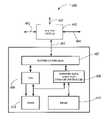
- FIG. 1is a diagram showing the partition of the SRAM and DRAM portions of the logical data
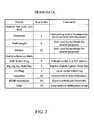
- FIG. 2is a table showing details of the SRAM portion of the logical data
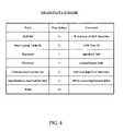
- FIG. 3is a table showing the details of the A, B, and C banks of the DRAM portion of the logical data
- FIG. 4is a table showing the details of the D bank of the DRAM portion of the logical data
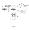
- FIG. 5is another diagram illustrating routing an Internet data packet using a longest prefix match
- FIG. 6is a block diagram of an Internet router according to embodiments of the present invention.
- FIG. 7is a flow diagram of method steps used in embodiments of the present invention.
- FIG. 8is a flow diagram of method steps used in embodiments of the present invention.
- FIG. 9is a block diagram of an Internetwork illustrating Internet connections.
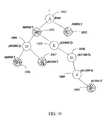
- FIG. 10is a diagram illustrating prefixes stored in a tree structure.
- IPv4 addressesare 32 bits long and are written in the following byte format.
- the Ipv4 addressis written as “x.x.x.x” where each “x” represents the decimal value of an 8 bit binary byte of the address.
- IPv4 addressesrange from 1.0.0.0 to 223.255.255.255. Addresses 0.0.0.0 to 0.255.255.255 and 224.0.0.0 to 255.255.255.255 have “special” uses not discussed in this disclosure.
- the IPv4 address formatcomprises an address and a subnet mask. For example, if an Internet address is 12.34.56.78 the mask will indicate the number of the bits in the address that are network bits with the remaining bits as host bits.
- the network bitsdefine the Internet connections accessing various physical networks.
- the physical networksconnect a number of host systems and also may connect to additional routers.
- an organizationmay have a large physical network (e.g., Ethernet) that connects all the systems within the organization.
- This organization's physical networkmay have one set of network bits that direct data to the organization's physical network. From that point the Host bits direct the data to the particular system which is the final destination.
- Multiple routersmay be connected to a particular physical network so that a final destination may be reached via multiple Internet network paths.
- the routing tables stored in a particular routerdefine those Internet network paths accessible by the router at a particular time.
- the above Internet addressmay be written as 12.34.56.78/255.255.255.0 with the bold numbers representing the mask. “255” indicates that all the bits in a corresponding 8 bit byte are part of the network bits. The three consecutive “255” make up 3 bytes or the 24 bits.
- This IPv4 addressmay also be written as 12.34.56.78/24. In this example, only the first 24 bits are network bits. The 24 bit mask therefore indicates the maximum number of bits that need to be examined to determine if a particular network connection will direct a received Internet data packet towards its final destination.
- a routermay be connected to a physical network which then connects all hosts with the 24 bit destination address prefix 12.34.56.78.
- the Internet routercan do no more in getting a data packet to its final destination at this point, it is up to the physical network to do the final delivery using the Host portion of the destination address.
- Network connections that will direct Internet data towards final destinations that have prefixes of 12.x.x.x, 12.34.x.x, 12.34.56.xall will direct the particular Internet data packet with destination address prefix 12.34.56.78 towards its final destination.
- the network connection that directs Internet data towards final destinations with the prefix of 12.34.56.xhas the “longest prefix match” and may be the best Next Hop for the particular final destination prefix 12.34.56.78/24.
- FIG. 10illustrates an example of a simple tree structure for storing a set of five bit prefixes.
- the syntaxis “xxxxx/y” or “prefix/length”.
- the “x's”represent binary bits (prefix) and “y” indicates how many bits (length) of the prefix are used. For example, “11111/4” is an all ones prefix where only the first foul bits are valid (used).
- the prefixes 10000/1, 00000/1, 00000/3, 00100/3, 01101/5are to be stored in a tree format.
- the root A 1001is the beginning and indicates that all five bit prefixes proceed from this point.
- first bit of the five bit prefixis a one
- a branchis taken to C 1002 .
- the first bitis a zero
- a branchis taken to B 1003 .
- Prefix 00000/3also has a first bit of zero and therefore it proceeds through B 1003 . From B 1003 branches are taken depending on whether the second bit is a one or a zero. If the second bit is a one the branch to E 1005 is taken and if it is a zero the branch to D 1004 is taken. None of the five prefixes given terminate at E 1005 or D 1004 as they all have more than two valid bits. From D 1004 branches are again taken based on the next (third) bit of the prefix. In this case, if the third bit is a one the branch is taken to G 1007 where prefix 00100/3 is stored. If the third bit is a zero the branch is taken to F 1008 where prefix 00000/3 is stored.
- the last prefix 01101/5has five valid bits and proceeds through E 1005 since the first two bits are 01. If the third bit is a one a branch is taken to H 1006 . Since there is no prefix with only three valid bits of 011, no prefix is stored at H 1006 . If the fourth bit is a zero in this path, then a branch is taken to I 1009 . All prefixes with the four valid bits of 0110 proceed through I 1009 . If the fifth bit is a one in this path, a branch is taken to J 1010 where prefix 01101/5 is stored. Again, J 1010 is a leaf of the tree 1000 .
- the prefixes in parenthesis at D 1004 , E 1005 , H 1006 , and I 1009indicate prefixes that would be stored at these locations if they existed.
- F 1008 , G 1007 and J 1010are considered leaf nodes because no branches are taken from these nodes. While a prefix is stored at B 1003 , node B 1003 is not a leaf node because branches are taken to intermediate nodes D 1004 and E 1005 from B 1003 .
- This exampleillustrates how a tree structure works. Methods exist in the arts on how to construct and how to search tree structures. The important point is that, depending on the prefix and length, one can find a stored prefix and access the data stored therein.
- Routing on the Internetmeans finding a communication path.
- the paths or directionsare derived from Internet connection data received from a routing protocol.
- Several alternative pathsmay exist when exiting one router and going to the next router or physical network (Next Hop) and option data describing the characteristics of the alternate paths is updated periodically or as the Internet connections change.
- the option datais based on topology, policies and metrics (Hop count, filtering, delay, bandwidth, etc.)
- the Internet connection data stored in router tablesis organized in a tree structure.
- the Internet connection datais sent to the routers and they build “maps” and determine “directions” for forwarding Internet data packets over the Internet network.
- the routerforwards Internet data packets by moving the packets between interfaces according to the “directions”.
- the directionsare in the form of Next Hop options that will move the Internet data packet towards a final destination based on how many of the bits in the packet's destination address matches the prefixes stored in the router tables.
- the router table tree structureis searched for the “longest” prefix that matches a corresponding number of bits in the destination address of the received Internet data packet.
- the longest prefix matchis found, there may be more than one Next Hop connection (direction) that will move the Internet data packet towards its final destination.
- Picking which optional Next Hop to takeis done based on data describing the “quality of service” requirement of the received Internet data packet and parameters describing a particular optional Next Hop's service characteristics.
- An algorithme.g., an Equal Cost Multi-Path takes this data and decides which of the Next Hop options to take for the particular received Internet data packet.
- FIG. 1is a block diagram illustrating the bits that may be stored as pail of the Internet data defining the Internet connections accessible with a particular router.
- Logical Internet connection data 100describes data that is normally stored in the router to define the connections accessible by the router.
- the logical Internet connection data 100includes Pattern and Equal Cost Multi-Path information (72 bits), three Next Hop addresses along with management data (128 bits each), and a Border Gateway Protocol (BGP) Next Hop data along with its management data (128 bits).
- Embodiments of the present inventionpartition this data as shown in FIG. 1 so that the Pattern and ECMP information is stored in static random access memory (SRAM) 101 .
- Next Hop one (NH1), NH2, NH3 and BGPare stored in dynamic random access memory (DRAM) Banks A 102 , B 103 , C 104 and D 105 , respectively.
- SRAMstatic random access memory
- DRAMdynamic random access memory
- FIG. 2is a table that lists the details of what is contained in the Pattern and ECMP data.
- the hardwarethat is searching the tables stored in the SRAM 101 uses the Prefix length field of 6 bits and the Pattern field of 32 bits. The remaining bits are used by the software algorithm to calculate the address in DRAM 106 that is accessed when a particular entry in the SRAM 101 is determined to be the LPM.
- FIG. 3illustrates the data stored in DRAM banks A 102 , B 103 and C 104 . Each of these banks represents one of the three potential Next Hop structures. The selection of which Next Hop to choose is made after execution of the ECMP algorithm.
- the thresholds used as inputs to the ECMP algorithmare obtained from the last two bytes of the SRAM 101 portion of the forwarding data as shown in FIG. 2 . By partitioning the data to put these thresholds in the SRAM 101 , the ECMP algorithm is applied before the DRAM 106 portion of the data needs to be accessed. This allows for an improvement in bandwidth allocation to the DRAM 106 memory by accessing fewer banks on a per frame basis (Internet data packet is a frame).
- FIG. 4is a block diagram illustrating the data stored in the bank D of DRAM 106 .
- the bank D 105contains the BGP Next Hop information along with overall data management parameters.
- FIG. 5is a diagram illustrating the connection between four routers, R 1 501 , R 2 502 , R 3 503 and R 4 504 .
- Router R 1 501is forwarding an Internet data packet 506 to router R 2 502 and has a destination IP address of 10.1.1.1.
- Router R 2 502has Internet connection data stored in its routing table 505 .
- Routing table 505indicates that Internet data packets with a prefix of 8 bits matching the decimal number 10 (binary 00001010) are forwarded to router R 3 503 if this is the longest prefix match. Likewise 16 bit prefixes matching 10.1 are forwarded to router R 4 504 .
- Prefixes with 8 bits matching 20are forwarded to router R 5 (not shown) and 8 bits matching 30 are forwarded to router R 6 (also not shown).
- the received Internet data packet 506has prefix bits that match both R 3 503 and R 4 504 , however, R 4 504 is the longest prefix match since the first 16 bits of the prefix match.
- Router R 2 502would pick router R 4 as the best Next Hop for Internet data packet 506 .
- FIG. 6is a block diagram of elements within a Internet router 600 according to embodiments of the present invention.
- Router switch 602is used to allow Internet data packet received on ports 601 , 603 and 604 to be forwarded to a next hop destination that best meets the requirements of the Internet data packet.
- Router controller 607receives Internet connection data describing which Next Hop destinations are accessible on a given port. The Internet connection data is updated periodically as connection configuration changes. This Internet connection data is stored in the Internet router 600 and is searched when an Internet data packet is received to find the best Next Hop destination for the data packet that fits its quality of service specifications.
- the Internet datais partitioned by Internet partition controller 608 into data that is searched with tree search engine (TSE) 609 and data that defines a set of Next Hop destination options.
- the data to be searchedis the set of destination addresses that are accessible via a given port or Internet connection accessible by a particular router (e.g., router 600 ).
- connection 604may be connected to another router that in turn has access to connections that lead to sets of final destinations.
- TSEtree search engine
- the searchable datais stored in fast SRAM 611 memory as it may take multiple reads to determine which connection option best fits a particular received Internet data packet.
- Option thresholdsare stored at the searchable addresses.
- the Next Hop options that are used to determine where to forward the Internet data packetare stored in slower DRAM 610 .
- the DRAM 610is partition into memory banks with each bank storing the data for a particular Next Hop option.
- the DRAM 610 storage addressis calculated with an ECMP algorithm that determines the DRAM 610 address from a corresponding SRAM 611 searchable address and the option threshold data stored therein at the SRAM 611 address locations. In this manner, DRAM 610 has to be read only once as the desired address is determined by reads of the fast SRAM and calculations of the ECMP algorithm.
- router 600When router 600 receives an Internet data packet, it is examined in Internet controller 607 for its destination address data and its quality of service criteria which in turn is used to determine which of the possible Next Hops is the best fit.
- TSE 609searches the stored data in SRAM 611 and determines which of the connection options has the longest prefix match with the received destination address of the Internet data packet. This may take two reads of SRAM 611 .
- the matchis made, the DRAM 610 address and a corresponding memory bank is calculated by the ECMP algorithm using the stored option threshold data and the quality of service data in the Internet data packet. DRAM 610 is then read only once to return data for forwarding the Internet data packet.
- Router controller 607then directs router switch 602 via 605 to forward the Internet data packet to the Next Hop destination address read from DRAM 610 .
- FIG. 7is a flow diagram of method steps used in embodiments of the present invention.
- step 701Internet data defining network router connections is received in the router 600 .
- controller 608partitions the Internet data into a search partition comprising Prefix data, Pattern data and ECMP threshold data and a forwarding data portion comprising Next Hop options.
- step 703the search partition is stored in a tree search format in SRAM 611 .
- step 703DRAM addresses are calculated from the SRAM address.
- the forwarding data portion comprising the Next Hop optionsare stored in memory banks at addresses determined algorithmically from the SRAM address.
- FIG. 8is a flow diagram of method steps used in embodiments of the present invention.
- an Internet data packetis received in router 600 .
- router 600uses Tree Search Engine (TSE) 609 to search SRAM 611 to determine the longest prefix match stored in the tables of SRAM 611 .
- TSETree Search Engine
- step 803data stored at the matched SRAM 611 location is outputted and provided to step 804 where an ECMP algorithm is run using the threshold data and quality of service data from within the Internet data packet.
- the DRAM addressis calculated algorithmically from the SRAM 611 address and the results of the ECMP algorithm of step 804 .
- step 806This is used to determine which particular DRAM 610 bank is accessed in step 806 to output the best Next Hop destination based on results from the ECMP algorithm.
- DRAM 610is accessed in step 806 using the generated addresses and the Next Hop forwarding data is outputted.
- step 807the forwarding data is used in the router controller 607 to make the correct connection for the received Internet data packet.
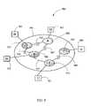
- FIG. 9is a block diagram of an Internetwork 900 illustrating Internet connections.
- Internet 902encompasses all of the physical networks P 904 , P 905 .
- P 908 , P 910 and P 915and the routers R 907 , R 909 , R 912 , R 914 , and R 916 .
- the Hosts H 901 , H 903 , H 906 , H 911 , and H 913communicate over the Internet 902 by sending data which gets forwarded by the routers R 907 , R 909 , R 912 , R 914 , and R 916 via the physical networks P 904 , P 905 , P 908 , P 910 and P 915 .
- may routesare possible from any one Host to any other Host by traversing the physical networks and the routers. All routes are not equal in the directness of path.
Landscapes
- Engineering & Computer Science (AREA)
- Computer Networks & Wireless Communication (AREA)
- Signal Processing (AREA)
- Data Exchanges In Wide-Area Networks (AREA)
Abstract
Description
Claims (21)
Priority Applications (1)
| Application Number | Priority Date | Filing Date | Title |
|---|---|---|---|
| US10/191,657US7260096B2 (en) | 2002-07-09 | 2002-07-09 | Method and router for forwarding internet data packets |
Applications Claiming Priority (1)
| Application Number | Priority Date | Filing Date | Title |
|---|---|---|---|
| US10/191,657US7260096B2 (en) | 2002-07-09 | 2002-07-09 | Method and router for forwarding internet data packets |
Publications (2)
| Publication Number | Publication Date |
|---|---|
| US20040008675A1 US20040008675A1 (en) | 2004-01-15 |
| US7260096B2true US7260096B2 (en) | 2007-08-21 |
Family
ID=30114197
Family Applications (1)
| Application Number | Title | Priority Date | Filing Date |
|---|---|---|---|
| US10/191,657Expired - Fee RelatedUS7260096B2 (en) | 2002-07-09 | 2002-07-09 | Method and router for forwarding internet data packets |
Country Status (1)
| Country | Link |
|---|---|
| US (1) | US7260096B2 (en) |
Cited By (9)
| Publication number | Priority date | Publication date | Assignee | Title |
|---|---|---|---|---|
| US20040174883A1 (en)* | 2001-02-16 | 2004-09-09 | Mathias Johansson | Method and arrangement for bandwidth shaping in data communications system |
| US20050138189A1 (en)* | 2003-04-23 | 2005-06-23 | Sunay Tripathi | Running a communication protocol state machine through a packet classifier |
| US20060126496A1 (en)* | 2004-12-10 | 2006-06-15 | Clarence Filsfils | Fast reroute (FRR) protection at the edge of a RFC 2547 network |
| US20060221960A1 (en)* | 2005-04-01 | 2006-10-05 | Gaetano Borgione | Performing extended lookups on mac-based tables |
| US20090103536A1 (en)* | 2002-08-29 | 2009-04-23 | International Business Machines Corporation | Method and System for Reducing Look-Up Time in Packet Forwarding on Computer Networks |
| WO2015032216A1 (en)* | 2013-09-09 | 2015-03-12 | 中兴通讯股份有限公司 | Routing lookup method and device, and construction method for b-tree structure |
| US20160087890A1 (en)* | 2014-09-19 | 2016-03-24 | Telefonaktiebolaget L M Ericsson (Publ) | Automated determination of tree attributes and assignment of receiver identifiers by distributed election in multicast architectures relying on packets identifying intended receivers |
| WO2016095439A1 (en)* | 2014-12-18 | 2016-06-23 | 中兴通讯股份有限公司 | Equal cost multi-path (ecmp) based packet transmission method and device |
| US20190372894A1 (en)* | 2018-06-05 | 2019-12-05 | NEC Laboratories Europe GmbH | Method and system for performing state-aware software defined networking |
Families Citing this family (33)
| Publication number | Priority date | Publication date | Assignee | Title |
|---|---|---|---|---|
| AU2003900991A0 (en)* | 2003-03-03 | 2003-03-20 | Intelliguard I.T. Pty. Ltd. | A firewall system |
| US6970464B2 (en)* | 2003-04-01 | 2005-11-29 | Cisco Technology, Inc. | Method for recursive BGP route updates in MPLS networks |
| US6917618B2 (en)* | 2003-04-02 | 2005-07-12 | Cisco Technology, Inc. | Arrangement in a router for generating a route based on a pattern of a received packet |
| US7697432B2 (en)* | 2003-06-27 | 2010-04-13 | Broadcom Corporation | Equal and weighted cost multipath load balancing in a network device |
| US7564869B2 (en) | 2004-10-22 | 2009-07-21 | Cisco Technology, Inc. | Fibre channel over ethernet |
| US7969971B2 (en) | 2004-10-22 | 2011-06-28 | Cisco Technology, Inc. | Ethernet extension for the data center |
| US8238347B2 (en)* | 2004-10-22 | 2012-08-07 | Cisco Technology, Inc. | Fibre channel over ethernet |
| US7830793B2 (en)* | 2004-10-22 | 2010-11-09 | Cisco Technology, Inc. | Network device architecture for consolidating input/output and reducing latency |
| US7602720B2 (en)* | 2004-10-22 | 2009-10-13 | Cisco Technology, Inc. | Active queue management methods and devices |
| US7801125B2 (en)* | 2004-10-22 | 2010-09-21 | Cisco Technology, Inc. | Forwarding table reduction and multipath network forwarding |
| US8320242B2 (en)* | 2004-12-24 | 2012-11-27 | Net Optics, Inc. | Active response communications network tap |
| US7961621B2 (en) | 2005-10-11 | 2011-06-14 | Cisco Technology, Inc. | Methods and devices for backward congestion notification |
| GB0524126D0 (en)* | 2005-11-26 | 2006-01-04 | Cogniscience Ltd | Data transmission method |
| CN100446508C (en)* | 2005-12-30 | 2008-12-24 | 华为技术有限公司 | A device and method for realizing message forwarding |
| US8259720B2 (en) | 2007-02-02 | 2012-09-04 | Cisco Technology, Inc. | Triple-tier anycast addressing |
| US8149710B2 (en) | 2007-07-05 | 2012-04-03 | Cisco Technology, Inc. | Flexible and hierarchical dynamic buffer allocation |
| US7898984B2 (en)* | 2007-08-07 | 2011-03-01 | Net Optics, Inc. | Enhanced communication network tap port aggregator arrangement and methods thereof |
| US7903576B2 (en)* | 2007-08-07 | 2011-03-08 | Net Optics, Inc. | Methods and arrangement for utilization rate display |
| US8094576B2 (en) | 2007-08-07 | 2012-01-10 | Net Optic, Inc. | Integrated switch tap arrangement with visual display arrangement and methods thereof |
| US8121038B2 (en) | 2007-08-21 | 2012-02-21 | Cisco Technology, Inc. | Backward congestion notification |
| US7876700B2 (en)* | 2007-12-14 | 2011-01-25 | Verizon Patent And Licensing Inc. | Method and system for providing default route advertisement protection |
| US7773529B2 (en) | 2007-12-27 | 2010-08-10 | Net Optic, Inc. | Director device and methods thereof |
| CA2780258C (en)* | 2009-11-30 | 2018-03-13 | International Business Machines Corporation | Packet communication system, communication method and program |
| US9306959B2 (en) | 2010-02-26 | 2016-04-05 | Ixia | Dual bypass module and methods thereof |
| US9813448B2 (en) | 2010-02-26 | 2017-11-07 | Ixia | Secured network arrangement and methods thereof |
| US8737197B2 (en) | 2010-02-26 | 2014-05-27 | Net Optic, Inc. | Sequential heartbeat packet arrangement and methods thereof |
| US8755293B2 (en) | 2010-02-28 | 2014-06-17 | Net Optics, Inc. | Time machine device and methods thereof |
| EP2540048B1 (en) | 2010-02-28 | 2019-07-17 | Keysight Technologies Singapore (Sales) Pte. Ltd. | Gigabits zero-delay tap and methods thereof |
| US9749261B2 (en) | 2010-02-28 | 2017-08-29 | Ixia | Arrangements and methods for minimizing delay in high-speed taps |
| US9183322B2 (en)* | 2012-12-04 | 2015-11-10 | Cisco Technology, Inc. | Increasing internet protocol version 6 host table scalability in top of rack switches for data center deployments |
| US9998213B2 (en) | 2016-07-29 | 2018-06-12 | Keysight Technologies Singapore (Holdings) Pte. Ltd. | Network tap with battery-assisted and programmable failover |
| JP7230729B2 (en)* | 2019-08-01 | 2023-03-01 | 日本電信電話株式会社 | Route control device, route control method, and program |
| US11431626B2 (en)* | 2020-10-05 | 2022-08-30 | Arista Networks, Inc. | Forwarding rules among lookup tables in a multi-stage packet processor |
Citations (15)
| Publication number | Priority date | Publication date | Assignee | Title |
|---|---|---|---|---|
| US5233604A (en) | 1992-04-28 | 1993-08-03 | International Business Machines Corporation | Methods and apparatus for optimum path selection in packet transmission networks |
| US5761440A (en)* | 1994-09-15 | 1998-06-02 | International Business Machines Corporation | System and method utilizing multiple search trees to route data within a data processing network |
| US5787255A (en) | 1996-04-12 | 1998-07-28 | Cisco Systems, Inc. | Internetworking device with enhanced protocol translation circuit |
| US6038233A (en) | 1996-07-04 | 2000-03-14 | Hitachi, Ltd. | Translator for IP networks, network system using the translator, and IP network coupling method therefor |
| US6055561A (en) | 1996-10-02 | 2000-04-25 | International Business Machines Corporation | Mapping of routing traffic to switching networks |
| US6118784A (en) | 1996-11-01 | 2000-09-12 | Hitachi, Ltd. | Communicating method between IPv4 terminal and IPv6 terminal and IPv4-IPv6 converting apparatus |
| US6157644A (en) | 1997-10-07 | 2000-12-05 | Northern Telecom Limited | Method and apparatus for accelerating OSI layer 3 routers |
| US6172927B1 (en) | 1997-04-01 | 2001-01-09 | Ramtron International Corporation | First-in, first-out integrated circuit memory device incorporating a retransmit function |
| US6189044B1 (en) | 1998-10-14 | 2001-02-13 | Hughes Electronics Corporation | Dynamic routing method for packet switched satellite communications |
| US6272132B1 (en) | 1998-06-11 | 2001-08-07 | Synchrodyne Networks, Inc. | Asynchronous packet switching with common time reference |
| US6335873B1 (en) | 1999-03-15 | 2002-01-01 | Nec Corporation | Semiconductor integrated circuit device |
| US6434144B1 (en)* | 1998-07-06 | 2002-08-13 | Aleksey Romanov | Multi-level table lookup |
| US20020172203A1 (en)* | 2000-11-16 | 2002-11-21 | Hongbin Ji | Fast IP route lookup with 16/K and 16/Kc compressed data structures |
| US6526056B1 (en)* | 1997-12-23 | 2003-02-25 | Cisco Technology, Inc. | Virtual private network employing tag-implemented egress-channel selection |
| US6985483B2 (en)* | 2001-07-31 | 2006-01-10 | North Carolina State University | Methods and systems for fast packet forwarding |
- 2002
- 2002-07-09USUS10/191,657patent/US7260096B2/ennot_activeExpired - Fee Related
Patent Citations (15)
| Publication number | Priority date | Publication date | Assignee | Title |
|---|---|---|---|---|
| US5233604A (en) | 1992-04-28 | 1993-08-03 | International Business Machines Corporation | Methods and apparatus for optimum path selection in packet transmission networks |
| US5761440A (en)* | 1994-09-15 | 1998-06-02 | International Business Machines Corporation | System and method utilizing multiple search trees to route data within a data processing network |
| US5787255A (en) | 1996-04-12 | 1998-07-28 | Cisco Systems, Inc. | Internetworking device with enhanced protocol translation circuit |
| US6038233A (en) | 1996-07-04 | 2000-03-14 | Hitachi, Ltd. | Translator for IP networks, network system using the translator, and IP network coupling method therefor |
| US6055561A (en) | 1996-10-02 | 2000-04-25 | International Business Machines Corporation | Mapping of routing traffic to switching networks |
| US6118784A (en) | 1996-11-01 | 2000-09-12 | Hitachi, Ltd. | Communicating method between IPv4 terminal and IPv6 terminal and IPv4-IPv6 converting apparatus |
| US6172927B1 (en) | 1997-04-01 | 2001-01-09 | Ramtron International Corporation | First-in, first-out integrated circuit memory device incorporating a retransmit function |
| US6157644A (en) | 1997-10-07 | 2000-12-05 | Northern Telecom Limited | Method and apparatus for accelerating OSI layer 3 routers |
| US6526056B1 (en)* | 1997-12-23 | 2003-02-25 | Cisco Technology, Inc. | Virtual private network employing tag-implemented egress-channel selection |
| US6272132B1 (en) | 1998-06-11 | 2001-08-07 | Synchrodyne Networks, Inc. | Asynchronous packet switching with common time reference |
| US6434144B1 (en)* | 1998-07-06 | 2002-08-13 | Aleksey Romanov | Multi-level table lookup |
| US6189044B1 (en) | 1998-10-14 | 2001-02-13 | Hughes Electronics Corporation | Dynamic routing method for packet switched satellite communications |
| US6335873B1 (en) | 1999-03-15 | 2002-01-01 | Nec Corporation | Semiconductor integrated circuit device |
| US20020172203A1 (en)* | 2000-11-16 | 2002-11-21 | Hongbin Ji | Fast IP route lookup with 16/K and 16/Kc compressed data structures |
| US6985483B2 (en)* | 2001-07-31 | 2006-01-10 | North Carolina State University | Methods and systems for fast packet forwarding |
Non-Patent Citations (3)
| Title |
|---|
| "Light Reading-The Global Site for Optical Network," via Internet at wysiwyg://54/http://www.lightreading.com/document.asp?doc<SUB>-</SUB>id =4009&page<SUB>-</SUB>number=5, pp. 1-2. |
| "New caching scheme for routing table lookups," IBM Research Disclosure, Aug. 2001, p. 1378. |
| Y-C Liu et al. "Fast IP Table Lookup and Memory Reduction," IEEE, 2001, pp. 228-232. |
Cited By (19)
| Publication number | Priority date | Publication date | Assignee | Title |
|---|---|---|---|---|
| US20040174883A1 (en)* | 2001-02-16 | 2004-09-09 | Mathias Johansson | Method and arrangement for bandwidth shaping in data communications system |
| US20090103536A1 (en)* | 2002-08-29 | 2009-04-23 | International Business Machines Corporation | Method and System for Reducing Look-Up Time in Packet Forwarding on Computer Networks |
| US7788406B2 (en)* | 2002-08-29 | 2010-08-31 | International Business Machines Corporation | Method and system for reducing look-up time in packet forwarding on computer networks |
| US20050138189A1 (en)* | 2003-04-23 | 2005-06-23 | Sunay Tripathi | Running a communication protocol state machine through a packet classifier |
| US7363383B2 (en)* | 2003-04-23 | 2008-04-22 | Sun Microsytems, Inc. | Running a communication protocol state machine through a packet classifier |
| US20090245259A1 (en)* | 2004-12-10 | 2009-10-01 | Cisco Technology, Inc. | Fast reroute (frr) protection at the edge of a rfc 2547 network |
| US7551551B2 (en)* | 2004-12-10 | 2009-06-23 | Cisco Technology, Inc. | Fast reroute (FRR) protection at the edge of a RFC 2547 network |
| US20060126496A1 (en)* | 2004-12-10 | 2006-06-15 | Clarence Filsfils | Fast reroute (FRR) protection at the edge of a RFC 2547 network |
| US7983153B2 (en) | 2004-12-10 | 2011-07-19 | Cisco Technology, Inc. | Fast reroute (FRR) protection at the edge of a RFC 2547 network |
| US7586895B2 (en)* | 2005-04-01 | 2009-09-08 | Cisco Technology, Inc. | Performing extended lookups on MAC-based tables including level 3 multicast group destination addresses |
| US20060221960A1 (en)* | 2005-04-01 | 2006-10-05 | Gaetano Borgione | Performing extended lookups on mac-based tables |
| CN104426770A (en)* | 2013-09-09 | 2015-03-18 | 中兴通讯股份有限公司 | Routing lookup method, routing lookup device and method for constructing B-Tree tree structure |
| WO2015032216A1 (en)* | 2013-09-09 | 2015-03-12 | 中兴通讯股份有限公司 | Routing lookup method and device, and construction method for b-tree structure |
| US20160087890A1 (en)* | 2014-09-19 | 2016-03-24 | Telefonaktiebolaget L M Ericsson (Publ) | Automated determination of tree attributes and assignment of receiver identifiers by distributed election in multicast architectures relying on packets identifying intended receivers |
| US9749220B2 (en)* | 2014-09-19 | 2017-08-29 | Telefonaktiebolaget L M Ericsson (Publ) | Automated determination of tree attributes and assignment of receiver identifiers by distributed election in multicast architectures relying on packets identifying intended receivers |
| US10439928B2 (en) | 2014-09-19 | 2019-10-08 | Telefonaktiebolaget Lm Ericsson (Publ) | Automated determination of tree attributes and assignment of receiver identifiers by distributed election in multicast architectures relying on packets identifying intended receivers |
| WO2016095439A1 (en)* | 2014-12-18 | 2016-06-23 | 中兴通讯股份有限公司 | Equal cost multi-path (ecmp) based packet transmission method and device |
| US20190372894A1 (en)* | 2018-06-05 | 2019-12-05 | NEC Laboratories Europe GmbH | Method and system for performing state-aware software defined networking |
| US10892985B2 (en)* | 2018-06-05 | 2021-01-12 | Nec Corporation | Method and system for performing state-aware software defined networking |
Also Published As
| Publication number | Publication date |
|---|---|
| US20040008675A1 (en) | 2004-01-15 |
Similar Documents
| Publication | Publication Date | Title |
|---|---|---|
| US7260096B2 (en) | Method and router for forwarding internet data packets | |
| US7660314B2 (en) | Apparatus and method for multi-protocol route redistribution in a massively parallel router | |
| US5917820A (en) | Efficient packet forwarding arrangement for routing packets in an internetwork | |
| US6876654B1 (en) | Method and apparatus for multiprotocol switching and routing | |
| EP1344152B1 (en) | Apparatus and method for performing high-speed ip route lookup and managing routing/forwarding tables | |
| US7787466B1 (en) | Nexthop to a forwarding table | |
| US5991300A (en) | Technique for efficiently performing optional TTL propagation during label imposition | |
| US7782874B2 (en) | Apparatus and method for route summarization and distribution in a massively parallel router | |
| US7039018B2 (en) | Technique to improve network routing using best-match and exact-match techniques | |
| US8014293B1 (en) | Scalable route resolution | |
| JP4076586B2 (en) | Systems and methods for multilayer network elements | |
| US6678269B1 (en) | Network switching device with disparate database formats | |
| US8194664B2 (en) | Two-level load-balancing of network traffic over an MPLS network | |
| US9559953B2 (en) | Path splitting with a connection-oriented network | |
| US9106506B2 (en) | Filter-based forwarding in a network | |
| US7277386B1 (en) | Distribution of label switched packets | |
| KR100666996B1 (en) | Routing System and Route Update Methods | |
| US7624226B1 (en) | Network search engine (NSE) and method for performing interval location using prefix matching | |
| US8170026B2 (en) | Method and apparatus for virtual circuit routes | |
| US6947415B1 (en) | Method and apparatus for processing packets in a routing switch | |
| US7103035B1 (en) | Arrangement for searching network addresses in a network switch using multiple tables based on subnet identifier | |
| US7702882B2 (en) | Apparatus and method for performing high-speed lookups in a routing table | |
| US7352748B1 (en) | Updating of routing data in a network element | |
| RU2233473C2 (en) | Device and method for performing high-speed search for routes of internet protocol and controlling routing/transfer tables | |
| KR100475436B1 (en) | distributed router and ARP packet processing method thereof |
Legal Events
| Date | Code | Title | Description |
|---|---|---|---|
| AS | Assignment | Owner name:INTERNATIONAL BUSINESS MACHINES CORPORATION, NEW Y Free format text:ASSIGNMENT OF ASSIGNORS INTEREST;ASSIGNORS:BASSO, CLAUDE;POVSE, MAX ROBERT;VAIDHYANATHAN, NATARAJAN;AND OTHERS;REEL/FRAME:013100/0072 Effective date:20020708 | |
| FEPP | Fee payment procedure | Free format text:PAYOR NUMBER ASSIGNED (ORIGINAL EVENT CODE: ASPN); ENTITY STATUS OF PATENT OWNER: LARGE ENTITY | |
| STCF | Information on status: patent grant | Free format text:PATENTED CASE | |
| REMI | Maintenance fee reminder mailed | ||
| FPAY | Fee payment | Year of fee payment:4 | |
| SULP | Surcharge for late payment | ||
| AS | Assignment | Owner name:GOOGLE INC., CALIFORNIA Free format text:ASSIGNMENT OF ASSIGNORS INTEREST;ASSIGNOR:INTERNATIONAL BUSINESS MACHINES CORPORATION;REEL/FRAME:026664/0866 Effective date:20110503 | |
| FPAY | Fee payment | Year of fee payment:8 | |
| AS | Assignment | Owner name:GOOGLE LLC, CALIFORNIA Free format text:CHANGE OF NAME;ASSIGNOR:GOOGLE INC.;REEL/FRAME:044127/0735 Effective date:20170929 | |
| FEPP | Fee payment procedure | Free format text:MAINTENANCE FEE REMINDER MAILED (ORIGINAL EVENT CODE: REM.); ENTITY STATUS OF PATENT OWNER: LARGE ENTITY | |
| LAPS | Lapse for failure to pay maintenance fees | Free format text:PATENT EXPIRED FOR FAILURE TO PAY MAINTENANCE FEES (ORIGINAL EVENT CODE: EXP.); ENTITY STATUS OF PATENT OWNER: LARGE ENTITY | |
| STCH | Information on status: patent discontinuation | Free format text:PATENT EXPIRED DUE TO NONPAYMENT OF MAINTENANCE FEES UNDER 37 CFR 1.362 | |
| FP | Lapsed due to failure to pay maintenance fee | Effective date:20190821 |