US7259630B2 - Elimination of peak clipping and improved efficiency for RF power amplifiers with a predistorter - Google Patents
Elimination of peak clipping and improved efficiency for RF power amplifiers with a predistorterDownload PDFInfo
- Publication number
- US7259630B2 US7259630B2US10/625,761US62576103AUS7259630B2US 7259630 B2US7259630 B2US 7259630B2US 62576103 AUS62576103 AUS 62576103AUS 7259630 B2US7259630 B2US 7259630B2
- Authority
- US
- United States
- Prior art keywords
- coupled
- look
- power
- input signal
- output
- Prior art date
- Legal status (The legal status is an assumption and is not a legal conclusion. Google has not performed a legal analysis and makes no representation as to the accuracy of the status listed.)
- Expired - Lifetime
Links
Images

Classifications
- H—ELECTRICITY
- H03—ELECTRONIC CIRCUITRY
- H03F—AMPLIFIERS
- H03F1/00—Details of amplifiers with only discharge tubes, only semiconductor devices or only unspecified devices as amplifying elements
- H03F1/32—Modifications of amplifiers to reduce non-linear distortion
- H03F1/3241—Modifications of amplifiers to reduce non-linear distortion using predistortion circuits
- H03F1/3294—Acting on the real and imaginary components of the input signal
- H—ELECTRICITY
- H03—ELECTRONIC CIRCUITRY
- H03F—AMPLIFIERS
- H03F1/00—Details of amplifiers with only discharge tubes, only semiconductor devices or only unspecified devices as amplifying elements
- H03F1/02—Modifications of amplifiers to raise the efficiency, e.g. gliding Class A stages, use of an auxiliary oscillation
- H03F1/0205—Modifications of amplifiers to raise the efficiency, e.g. gliding Class A stages, use of an auxiliary oscillation in transistor amplifiers
- H03F1/0211—Modifications of amplifiers to raise the efficiency, e.g. gliding Class A stages, use of an auxiliary oscillation in transistor amplifiers with control of the supply voltage or current
- H—ELECTRICITY
- H03—ELECTRONIC CIRCUITRY
- H03F—AMPLIFIERS
- H03F1/00—Details of amplifiers with only discharge tubes, only semiconductor devices or only unspecified devices as amplifying elements
- H03F1/32—Modifications of amplifiers to reduce non-linear distortion
- H03F1/3241—Modifications of amplifiers to reduce non-linear distortion using predistortion circuits
- H03F1/3247—Modifications of amplifiers to reduce non-linear distortion using predistortion circuits using feedback acting on predistortion circuits
- H—ELECTRICITY
- H03—ELECTRONIC CIRCUITRY
- H03F—AMPLIFIERS
- H03F2200/00—Indexing scheme relating to amplifiers
- H03F2200/102—A non-specified detector of a signal envelope being used in an amplifying circuit
- H—ELECTRICITY
- H03—ELECTRONIC CIRCUITRY
- H03F—AMPLIFIERS
- H03F2200/00—Indexing scheme relating to amplifiers
- H03F2200/336—A I/Q, i.e. phase quadrature, modulator or demodulator being used in an amplifying circuit
- H—ELECTRICITY
- H03—ELECTRONIC CIRCUITRY
- H03F—AMPLIFIERS
- H03F2201/00—Indexing scheme relating to details of amplifiers with only discharge tubes, only semiconductor devices or only unspecified devices as amplifying elements covered by H03F1/00
- H03F2201/32—Indexing scheme relating to modifications of amplifiers to reduce non-linear distortion
- H03F2201/3233—Adaptive predistortion using lookup table, e.g. memory, RAM, ROM, LUT, to generate the predistortion
Definitions
- This inventionrelates generally to amplifiers, and more particularly to reducing clipping while improving efficiency in such amplifiers.
- Wireless communications services within a cellular networkare provided through individual geographic areas or “cells.”
- a cell sitehas generally included a cellular tower, having RF antennas that communicate with a plurality of remote devices, such as cellular phones and paging devices, and a base terminal station (BTS).
- a BTStypically includes one or more radio frequency (RF) power amplifiers coupled to the RF antennas for transmitting wireless communication signals to the remote devices.
- RFradio frequency
- Cellular networksmay provide services using digital modulation schemes. Such modulation schemes may include time division multiple access (TDMA), code division multiple access (CDMA), and Global System for Mobile communications (GSM), as well as others.
- TDMAtime division multiple access
- CDMAcode division multiple access
- GSMGlobal System for Mobile communications
- the output power of the amplifieris equal to the input power of the amplifier multiplied by a constant (K), i.e., the amplification or gain factor, and does not vary with input power level.
- Ka constant
- the phase of the output signalis the same as the phase of the input signal. Practically, both the output power and phase vary as a function of the input signal.
- an RF power amplifierhas three operating regions.
- the first region, or linear regionincludes operation where input signal power levels are relatively small and K remains constant. In the linear region, the response of an amplifier closely approximates that of an ideal amplifier.
- the second and third regionsare referred to as non-linear regions.
- the second region or compression regionbegins where input power levels have increased to the point that K begins to reduce or roll-off with further increases in input power.
- the third region or saturation regionis where the output power of the amplifier fails to increase with an increase in input power.
- Transistor devices used in RF power amplifiersare coupled to a direct current (DC) power supply, and are biased, in part, based on the voltage of the DC power supply.
- the selection of the bias point or quiescent operating point of the transistor devicealso determines the efficiency and the distribution of intermodulation distortion products generated by the device, and thereby determines the spectral purity of signals amplified by the RF power amplifier.
- Transistors particularly suited to operation in the 500 Megahertz (MHz) to 3.5 Gigahertz (GHz) range and that are typically used in RF power amplifiers in BTSare often lateral diffusion metal oxide semiconductor (LDMOS) devices.
- LDMOS devicesoffer excellent thermal characteristics due to advanced flange materials.
- Other suitable transistorsmay be GaAs, SiGe, SiC, and GaN devices.
- RF power amplifiersmay be characterized and compared using their efficiency and spectral purity. RF power amplifiers may also be selected for a particular application based on their efficiency and spectral purity. Moreover, RF power amplifier suppliers often differentiate themselves based on efficiency and spectral purity.
- efficiency and spectral purityare typically mutually exclusive. For example, in order improve spectral purity the output power of the RF power amplifier must be reduced, causing an increase in the thermal dissipation of transistor devices in the RF power amplifier while the efficiency suffers. Conversely, in order to increase the output power and improve efficiency, the spectral purity of the RF amplifier often suffers.
- feed-forward techniquesdeveloped to reduce non-linearities in amplifiers may be categorized as either feed-forward, feedback or predistortion, each having their respective advantages and disadvantages.
- the feed-forward techniqueattenuates a portion of an RF power amplifier output signal so that it is the same level as the input signal. The difference between this distorted output signal and the input signal is used to generate an error signal. The error signal is then amplified and subtracted from the RF power amplifier output, improving the linearity of the RF power amplifier.
- feed-forward techniquesare capable of handling multi-carrier signals, but do so at the expense of efficiency.
- the feedback techniqueuses synchronously demodulated output signals as the feedback information, forming a feedback loop. These signals are subtracted from the input signals, generating loop error signals. If the feedback loop gain is sufficient, the loop error signals continuously correct any non-linearity in the RF power amplifier response.
- feedback techniques used with RF power amplifiersprovide a reduction in out of band emissions, while being easily implemented. However, stability requirements limit bandwidth due to a dependence on loop delay. Thus, feedback techniques are of limited utility when used with certain modulation schemes.
- the predistortion techniqueprovides an appropriately distorted signal to the RF power amplifier, so that the RF power amplifier output is a scaled replica of the input signal.
- One type of predistorteruses a fixed signal predistortion circuit prior to amplification.
- a fixed type predistorteris of limited utility when used with digital modulation scheme having a fluctuating envelope, and does not account for changes, or drifts, in RF power amplifiers used therewith.
- Another type of predistorteris an adaptive predistorter.
- the amplitude modulation to amplitude modulation (AM-AM) and the amplitude modulation to phase modulation (AM-PM) characteristics of an RF power amplifierare estimated, using cubic spline interpolation, from a look-up table of distortion values generated using synchronous demodulation from the RF power amplifier output. The estimated values are then used to predistort the input signal to the RF power amplifier.
- the performance of an adaptive predistorteris typically comparable with that of negative feedback and feed-forward techniques without being limited in the modulation scheme used or suffering from drift.
- such an adaptive predistorteroperates as follows. First, a digital signal or a baseband signal is encoded into in-phase (I) and quadrature-phase (Q) components. The I/Q components then pass through a pulse-shaping filter to ensure free-symbol-interference (FSI). The I/Q signals are then applied to a squaring circuit that produces a scalar value (Vm) 2 indicative of the power of the baseband input signal. The scalar value (Vm) 2 is then used as a pointer to a look-up table that contains predistortion values for the I/Q components.
- Iin-phase
- Qquadrature-phase
- FSIfree-symbol-interference
- the predistortion valuesare then multiplied with the I/Q components, generating predistorted signals I d and Q d , respectively.
- the predistorted signals I d and Q dare then converted to analog signals and applied to a quadrature modulator.
- the quadrature modulatordriven by an oscillator, generates a modulated RF signal that is applied to the RF power amplifier.
- a portion of the RF power amplifier outputis applied to a quadrature demodulator, driven by the same oscillator, to produce I/Q baseband signals.
- the I/Q baseband signalsare converted into digital signals (I′/Q′).
- I′/Q′are then compared to I/Q, respectively, to estimate the AM-AM and AM-PM characteristics of the RF power amplifier. Since there is a delay in time between when the predistorted signals I d /Q d are applied to the RF power amplifier and the time that digital signals I′/Q′ are developed, the input signals I/Q must be delayed by that same amount of time before making the comparison.
- a predistorterin comparing I/Q signals, may be said to be “correlated” and “adaptive” in that the values in the look-up table change with time.
- Such correlated adaptive predistortersmay use cubic spline interpolation in estimating the AM-AM and AM-PM characteristics for values of (Vm) 2 , using values stored in the look-up table. Accuracy equivalent to that afforded by cubic spline interpolation requires a high order polynomial for a single polynomial fit. Although the use or application of cubic spline interpolation avoids the need for higher order polynomials in linearizing the response of an RF power amplifier, such correlated adaptive predistorters are still complex and costly by virtue of the delay and demodulation circuits used therein.
- predistortionis one technique that may be used to improve the spectral purity of a RF power amplifier without reducing the efficiency of the amplifier
- one problem with predistortionis the improvement to spectral purity is quickly reduced, or thwarted, if clipping of the waveform occurs in the amplifier.
- the waveforms typically associated with communications system using the IS-95, CDMA2000, and Universal Mobile Telecommunications System (UMTS) communications standardsall may experience peak power levels that may be anywhere from 6 to 12 decibels (dB) greater than average power levels. As a result, a high probability of clipping RF power amplifier used in such systems exists.
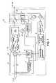
- FIG. 1is a schematic diagram of a first embodiment of an uncorrelated adaptive predistorter including a power supply control circuit in accordance with the principles of the present invention
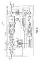
- FIG. 2is a schematic diagram of a second embodiment of an uncorrelated adaptive predistorter including a power supply control circuit in accordance with the principles of the present invention.
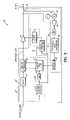
- FIG. 3is a schematic diagram of a third embodiment of an uncorrelated adaptive predistorter including a power supply control circuit in accordance with the principles of the present invention.
- an RF power amplifier and a predistorter including a peak control circuit for use therewithThe predistorter is configured to reduce non-linearities in the response of the RF power amplifier, thereby allowing an increase in efficiency, while the peak control circuit is configured to increase the power supply voltage to the RF power amplifier, thereby providing the RF power amplifier with the headroom necessary to provide peak instantaneous power demands without clipping.
- the predistortercomprises an input loop including a digitally based look-up table (LUT) and an output loop that measures an intermodulation distortion (IMD) product of the RF power amplifier.
- IMDintermodulation distortion
- a spline functionis used to produce an optimal set of values in the LUT such that an IMD product of the RF power amplifier in the output loop is minimized.
- the peak control circuitmay be further configured to reduce the power supply voltage in low power operation.
- a first embodiment 20 of an amplifier systemcomprises an RF power amplifier 10 and a predistorter 12 including a peak control circuit 70 .
- RF power amplifier 10is typical of RF power amplifiers known to those skilled in the art having linear, compression, and saturation regions of operation.
- RF power amplifier 10may also be a single channel or a multi-channel amplifier or a class AB or class B amplifier.
- RF power amplifier 10may be a lateral diffusion metal oxide semiconductor (LDMOS) particularly suited to operation in the 500 Megahertz (MHz) to 3.5 Gigahertz (GHz) range typically used in communications systems base terminal stations (BTS).
- LDMOSlateral diffusion metal oxide semiconductor
- RF power amplifier 10may also be a GaAs, SiGe, SiC, or GaN semiconductor device.
- Predistorter 12comprises an input loop 18 , an output loop 16 , and a peak control circuit 70 .
- Input loop 18comprises magnitude detection circuit 22 , LUT 14 , complex multiplier 24 , real and imaginary circuits 26 , 28 , digital-to-analog converters (DACs) 30 , 32 , quadrature modulator 34 , and RF oscillator 36 .
- Output loop 16comprises coupler 38 , mixer 40 , local oscillator 42 , amplifier 44 , bandpass filter (BPF) 46 , intermediate frequency to baseband conversion circuit 48 , and processor 52 .
- Peak control circuit 70comprises threshold detector 72 and power supply 74 .
- input loop 18accepts an input signal of the type including in-phase and quadrature-phase components I+jQ, referred to herein as a “baseband signal”, coupling the signal I+jQ to magnitude detection circuit 22 and complex multiplier 24 .
- Magnitude detection circuit 22produces a scalar value, e.g., I 2 +Q 2 , representative of a monotonically increasing function of the input power, e.g., power, logarithm of the input power, square root of the input power, etc., of the signal I+jQ that functions as an index to LUT 14 .
- LUT 14contains predistortion values, e.g., I′′, Q′′, for the in-phase (I) and quadrature-phase (Q) components of signal I+jQ.
- the initial values in LUT 14may be determined in one of a number of ways. For example, a calibration routine may be used to determine the transfer characteristics of a particular RF power amplifier, and the initial values in a LUT may be based thereon. Similarly, a particular family or type of RF power amplifiers may be characterized and the initial values in a LUT may be based on such a generalized characterization. Other methods of characterizing the performance of an amplifier and populating a LUT will readily appear to those of skill in the art.
- LUT 14couples the initial predistortion values to complex multiplier 24 where the predistortion values I′′, Q′′ are multiplied with signal I+jQ, forming predistorted signal I′+jQ′.
- Complex multiplier 24couples the in-phase (I′) and quadrature phase (Q′) components of predistorted signal I′+jQ′, to real (RE( )) and imaginary (IM( )) circuits, as indicated at reference numerals 26 and 28 , respectively.
- Real and imaginary circuits 26 , 28couple the in-phase (I′) and quadrature-phase (Q′) components of predistorted signal I′+jQ′to first and second DACs 30 , 32 , respectively.
- First and second DACs 30 , 32convert the real (I′) and imaginary (Q′) portions of the digital signal I′+jQ′ to analog signals, coupling the analog signals to quadrature modulator 34 .
- Quadrature modulator 34coupled to RF oscillator 36 , modulates the analog I′ and Q′ signals onto a carrier, and couples the carrier to RF power amplifier 10 , as indicated by signal A′(t)cos[ ⁇ ′t+ ⁇ ′(t)].
- RF power amplifier 10amplifies the signal A′(t)cos[ ⁇ ′t+ ⁇ ′(t)], and has an output signal as indicated at RF OPT.
- Such an output signal RF OPTmay be coupled to an antenna for purposes of communicating a digital in-phase and quadrature-phase signal I+jQ to a wireless device.
- Coupler 38is preferably a low loss coupler such that a minimal amount of power is lost in coupling output signal RF OPT to an antenna.
- Local oscillator 42is also coupled to mixer 40 .
- the frequency of local oscillator 42is selected so that mixer 40 couples an intermodulation distortion product, such as, for example, the third intermodulation distortion (3 rd IMD), of RF power amplifier 10 to amplifier 44 .
- an intermodulation distortion productsuch as, for example, the third intermodulation distortion (3 rd IMD)
- local oscillatormay be tunable in frequency or selected to produce a desired frequency such that one or more of the desired IMD products are selected.
- amplifier 44may not be required.
- amplifier 44amplifies and couples the 3 rd IMD product of RF power amplifier 10 to BPF 46 .
- BPF 46frequency selects the 3 rd IMD product of RF power amplifier 10 , coupling the 3 rd IMD product to intermediate frequency (I/F) to baseband converter circuit 48 .
- I/F to baseband converter circuit 48produces and couples a digital signal representative of the magnitude of the 3 rd IMD product to processor 52 .
- Processor 52selects an optimal set of predistortion values using a gradient search, i.e., comparing successive values of the magnitude of the 3rd IMD product, to minimize the 3rd IMD product and thereby improve the linearity of the response of RF power amplifier 10 .
- Processor 52also applies a spline function to update predistortion values in the LUT 14 .
- a spline functionSuch application involves analyzing the amplitude to amplitude (AM-AM) and amplitude to phase (AM-PM) predistortion curves, referring to the inputs and outputs of the RF power amplifier 10 respectively, and placing knots along the LUT 14 index to most closely resemble the transfer characteristics of RF power amplifier 10 .
- AM-AMamplitude to amplitude
- AM-PMamplitude to phase
- each knotis then varied in magnitude only. For example, during operation, the magnitude of each knot is changed, predistortion values are generated, and the 3rd IMD product is measured to determine whether the change in the magnitude of the knot improved the 3 rd IMD performance. This process is repeated continuously to improve the spectral purity of RF power amplifier 10 .
- knot placement along the LUT indexmay also be varied.
- the complexity of the processing performed by a processor, such as processor 52is essentially doubled.
- coupler 38 , mixer 40 , local oscillator 42 , amplifier 44 , BPF 46 , detector 48 , ADC 50 , and processor 52may be used as desired to select one or more intermodulation distortion products from the output of a RF power amplifier.
- coupler 38 , mixer 40 , local oscillator 42 , amplifier 44 , BPF 46 , detector 48 , ADC 50 , and processor 52are shown for purposes of example and are, therefore, merely exemplary in nature.
- threshold detector 72is coupled to magnitude detection circuit 22 and power supply 74 .
- Power supply 74is coupled to RF power amplifier 10 .
- Power supply 74acts as a voltage supply for RF power amplifier 10 , the nominal voltage of which determines, in part, the quiescent operating point or bias of RF power amplifier 10 .
- Threshold detector 72like LUT 14 , receives a monotonically increasing function that is representative of the input power from magnitude detection circuit 22 , and uses the function to change or select the voltage of power supply 74 based on the input power.
- power supply 74may operate at a nominal voltage of 27 volts direct current (DC). However, when the power of the signal I+jQ exceeds a high end set point, or threshold, of threshold detector 72 , power supply 74 may switch to 32 volts DC, or perhaps some other advantageous voltage, to provide RF amplifier 10 with the headroom to provide the peak instantaneous power demand by the signal I+jQ without clipping. When the power in the signal I+jQ drops back below the high end threshold, power supply 74 returns to nominal 27 volt DC operation.
- threshold detector 72 in peak control circuit 70may advantageously include a low end threshold configured to reduce the voltage, e.g., 24 volts, of power supply 74 when the power in input signal I+jQ drops below a low end threshold.
- a low end thresholdconfigured to reduce the voltage, e.g., 24 volts, of power supply 74 when the power in input signal I+jQ drops below a low end threshold.
- Such low power operationis particularly useful in increasing the overall capacity of particular communications systems, e.g., code division multiple access (CDMA).
- CDMAcode division multiple access
- such an embodiment 20may be thought of as an open loop configuration, being unconditionally stable, the output loop 16 being closed only for purposes of updating predistortion values in LUT 14 .
- such an embodiment 20may be referred to as “adaptive” in that predistortion values in the look-up table change with time.
- Such an embodiment 20may also be referred to as “uncorrelated” since the predistortion values that are applied are based on the 3 rd IMD product of a previous in-phase and quadrature-phase signal, and not the in-phase and quadrature-phase signal the RF power amplifier is about to amplify as in a correlated adaptive predistorter.
- predistortion values in LUT 14 for RF power amplifier 10will reflect operation based on those voltages.
- FIG. 2a second embodiment 20 ′ of an amplifier system is illustrated.
- Amplifier system 20 ′ in FIG. 2is similar to amplifier system 20 in FIG. 1 , differing only in the input loop 18 ′. Therefore, only input loop 18 ′ will be described. Otherwise, as will be appreciated by those skilled in the art, embodiment 20 ′ of FIG. 2 operates in like manner to embodiment 20 of FIG. 1 .
- Amplifier system 20 ′comprises an RF power amplifier 10 and a predistorter 12 ′.
- Predistorter 12 ′comprises an input loop 18 ′, an output loop 16 , and a peak control circuit 70 .
- Input loop 18 ′comprises a first converter circuit (I/Q to M/ ⁇ ) 54 , LUT 14 ′, multiplier circuit 56 , adder circuit 58 , a second converter circuit (M′/ ⁇ ′ to I′/Q′) 60 , digital-to-analog converters (DACs) 30 , 32 , quadrature modulator 34 , and RF oscillator 36 .
- input loop 18 ′accepts an input signal of the type including in-phase and quadrature-phase components I+jQ, coupling the signal I+jQ to first converter circuit (I/Q to M/ ⁇ ) 54 .
- First converter circuit (I/Q to M/ ⁇ ) 54converts signal I+jQ into magnitude M and phase ⁇ components.
- Magnitude component Mis coupled to multiplier circuit 56 , LUT 14 ′, and threshold detector 72 .
- Phase component ⁇is coupled to adder circuit 58 .
- Magnitude component Mfunctions as a scalar value representative of the power of the baseband signal I+jQ, and indexes LUT 14 ′.
- LUT 14 ′contains predistortion values G, ⁇ for the magnitude and phase components M, ⁇ , respectively, of baseband signal I+jQ.
- LUT 14 ′couples predistortion values G, ⁇ to multiplier circuit 56 and adder circuit 58 , respectively, where the predistortion values G, ⁇ are combined with the magnitude and phase components M, ⁇ of signal I+jQ, forming predistorted magnitude and phase components M′, ⁇ ′.
- Multiplier circuit 56 and adder circuit 58couple the predistorted magnitude and phase components M′, ⁇ ′ to second converter circuit (M′/ ⁇ ′ to I′/Q′) 60 .
- Second converter circuit (M′/ ⁇ ′ to I′/Q′) 60converts the predistorted magnitude and phase components M′, ⁇ ′ to in-phase I′ and quadrature-phase Q′ components of predistorted signal I′+jQ′.
- the in-phase I′ and quadrature-phase Q′ componentsare coupled to real (RE( )) and imaginary (IMO) circuits 26 , 28 , respectively.
- first and second DACs 30 , 32 , quadrature modulator 34 , and RF oscillator 36operate in like manner to that of input loop 18 of FIG. 1 .
- both amplifier system 20 of FIG. 1 and amplifier system 20 ′ of FIG. 2operate on a baseband input signal including in-phase and quadrature-phase components.
- amplifier system 20differs from amplifier system 20 ′ in that input loop 18 of FIG. 1 operates on the input signal in rectangular form (I/Q), whereas input loop 18 ′ of FIG. 2 operates on the input signal in polar form (M, ⁇ ).
- the present inventiondoes not rely on processing an input signal in any particular form.
- FIG. 3a third embodiment 20 ′′ of an amplifier system is illustrated.
- Amplifier system 20 ′′ in FIG. 3is similar to amplifier systems 20 and 20 ′ in FIGS. 1 and 2 , differing only in the input loop 18 ′′. Therefore, only input loop 18 ′′ is described.
- Embodiment 20 ′′ of FIG. 3operates in like manner to the embodiments 20 , 20 ′ of FIGS. 1 and 2 otherwise.
- Amplifier system 20 ′′comprises an RF power amplifier 10 and a predistorter 12 ′′.
- Predistorter 12 ′′comprises an input loop 18 ′′, an output loop 16 , and a peak control circuit 70 .
- Input loop 18 ′′comprises delay circuit 62 , envelope detector circuit 64 , analog-to-digital converter (ADC) 66 , complex attenuator 68 , and LUT 14 ′′.
- ADCanalog-to-digital converter
- input loop 18accepts an input signal of the type including in-phase and quadrature-phase components I+jQ, referred to herein as a “baseband signal”, coupling the signal I+jQ to envelope detection circuit 22 and complex multiplier 24 .
- Input loop 18 ′′accepts a modulated RF signal of the type A(t)cos[ ⁇ (t)+ ⁇ (t)].
- Signal A(t)cos[ ⁇ t+ ⁇ (t)]is coupled to delay circuit 62 and envelope detector circuit 64 .
- Envelope detector circuit 64produces a scalar value A(t) representative of the power of signal A(t)cos[ ⁇ (t)+ ⁇ (t)].
- a diodeis one example of an envelope detection circuit 64 .
- Envelope detector circuit 64is coupled to ADC 66 and threshold detector 72 .
- ADC 66converts scalar value A(t) to a digital signal that functions as an index to LUT 14 ′′.
- LUT 14 ′′contains predistortion values for the magnitude and phase components of input signal A(t)cos[ ⁇ (t)+ ⁇ (t)].
- LUT 14 ′′couples the predistortion values to complex attenuator 68 wherein the predistortion values effect the magnitude and phase components of input signal A(t)cos[ ⁇ (t)+ ⁇ (t)], forming predistorted signal A′(t)cos[ ⁇ ′(t)+ ⁇ ′(t)].
- Delay circuit 62allows enough time for detection and conversion such that signal A(t)cos[ ⁇ (t)+ ⁇ (t)] is coupled to the complex attenuator 68 at the same time as the predistiortion values.
- Complex attenuator 68couples the predistorted signal A′(t)cos[ ⁇ ′(t)+ ⁇ ′(t)] to RF power amplifier 10 .
- a power attenuator combined with a phase shiftermay function as a complex attenuator.
- a vector modulatormay be used as a complex attenuator.
- amplifier system 20 ′′ of FIG. 3operates on a sinusoidal or RF based input signal.
- input loop 18 ′′operates on an input signal in rectangular form (I/Q) and polar form (M, ⁇ ), respectively.
- input loop 18 ′′operates on a sinusoidal signal.
- the present inventionis not limited in the form of input signal used.
- a signal input to an uncorrelated adaptive predistortermay take any one of several forms, including but not limited to the types I+jQ and A(t)cos[ ⁇ (t)+ ⁇ (t)], representing in-phase and quadrature-phase components and a modulated carrier signal, respectively.
- an input loop 18 , 18 ′, 18 ′′may be configured accordingly to accommodate such signals. Additional advantages and modifications will readily appear to those skilled in the art. Therefore, the invention in its broader aspects is not limited to the specific details representative apparatus and method, and illustrative examples shown and described. Accordingly, departures may be made from such details without departure from the spirit or scope of applicants' general inventive concept.
Landscapes
- Engineering & Computer Science (AREA)
- Power Engineering (AREA)
- Physics & Mathematics (AREA)
- Nonlinear Science (AREA)
- Amplifiers (AREA)
Abstract
Description
Claims (45)
Priority Applications (1)
| Application Number | Priority Date | Filing Date | Title |
|---|---|---|---|
| US10/625,761US7259630B2 (en) | 2003-07-23 | 2003-07-23 | Elimination of peak clipping and improved efficiency for RF power amplifiers with a predistorter |
Applications Claiming Priority (1)
| Application Number | Priority Date | Filing Date | Title |
|---|---|---|---|
| US10/625,761US7259630B2 (en) | 2003-07-23 | 2003-07-23 | Elimination of peak clipping and improved efficiency for RF power amplifiers with a predistorter |
Publications (2)
| Publication Number | Publication Date |
|---|---|
| US20050017801A1 US20050017801A1 (en) | 2005-01-27 |
| US7259630B2true US7259630B2 (en) | 2007-08-21 |
Family
ID=34080267
Family Applications (1)
| Application Number | Title | Priority Date | Filing Date |
|---|---|---|---|
| US10/625,761Expired - LifetimeUS7259630B2 (en) | 2003-07-23 | 2003-07-23 | Elimination of peak clipping and improved efficiency for RF power amplifiers with a predistorter |
Country Status (1)
| Country | Link |
|---|---|
| US (1) | US7259630B2 (en) |
Cited By (31)
| Publication number | Priority date | Publication date | Assignee | Title |
|---|---|---|---|---|
| US20060046665A1 (en)* | 2002-05-01 | 2006-03-02 | Dali Yang | System and method for digital memorized predistortion for wireless communication |
| US20060108660A1 (en)* | 2004-11-19 | 2006-05-25 | Eudyna Devices Inc. | Amplifier circuit, control method of the same, and amplifier circuit module |
| US20060120479A1 (en)* | 2004-10-07 | 2006-06-08 | Cai Khiem V | System and method for crest factor reduction |
| US20070008033A1 (en)* | 2005-07-07 | 2007-01-11 | Hitachi Kokusai Electric Inc. | Predistortion amplifier for compensation distortion |
| US20070241812A1 (en)* | 2002-05-01 | 2007-10-18 | Dali Systems Co. Ltd. | High efficiency linearization power amplifier for wireless communication |
| US20080152037A1 (en)* | 2006-12-26 | 2008-06-26 | Dali System Co., Ltd. | Method and System for Baseband Predistortion Linearization in Multi-Channel Wideband Communication Systems |
| US20080174365A1 (en)* | 2002-05-01 | 2008-07-24 | Dali Systems Co. Ltd. | Power Amplifier Time-Delay Invariant Predistortion Methods and Apparatus |
| US20080186095A1 (en)* | 2007-02-01 | 2008-08-07 | Hitachi Kokusai Electric Inc. | Amplification apparatus |
| US20080197925A1 (en)* | 2004-09-21 | 2008-08-21 | Hitachi Kokusai Electric Inc. | Distortion Compensation Amplifying Apparatus |
| US20080265996A1 (en)* | 2002-05-01 | 2008-10-30 | Dali Systems Co., Ltd | Digital Hybrid Mode Power Amplifier System |
| US20080284509A1 (en)* | 2007-04-23 | 2008-11-20 | Dali Systems Co., Ltd | N-way doherty distributed power amplifier |
| US20080309405A1 (en)* | 2007-06-15 | 2008-12-18 | Broadcom Corporation | Power Amplifier Pre-Distortion |
| US20080310487A1 (en)* | 2007-06-15 | 2008-12-18 | Broadcom Corporation | Single-chip wireless tranceiver |
| US20080310557A1 (en)* | 2007-06-15 | 2008-12-18 | Broadcom Corporation | Carrier selection for multiple antennas |
| US20080310558A1 (en)* | 2007-06-15 | 2008-12-18 | Broadcom Corporation | Apparatus to reconfigure an 802.11a/n transceiver to support 802.11j/10 MHz mode of operation |
| US20090096521A1 (en)* | 2007-08-30 | 2009-04-16 | Dali Systems Co. Ltd. | Power amplifier predistortion methods and apparatus using envelope and phase detector |
| US20090128236A1 (en)* | 2003-02-19 | 2009-05-21 | Nujira Ltd. | High Efficiency Amplification |
| US20100033246A1 (en)* | 2008-08-11 | 2010-02-11 | Qualcomm Incorporated | Adaptive digital predistortion of complex modulated waveform using peak and rms voltage feedback from the output of a power amplifier |
| US20100141257A1 (en)* | 2007-05-04 | 2010-06-10 | Koninklijke Philips Electronics N.V. | Rf transmitter with digital feedback for mri |
| US20100176885A1 (en)* | 2007-04-23 | 2010-07-15 | Dali System Co. Ltd. | N-Way Doherty Distributed Power Amplifier with Power Tracking |
| US20100271957A1 (en)* | 2007-04-23 | 2010-10-28 | Dali Systems Co. Ltd. | Remotely Reconfigurable Power Amplifier System and Method |
| US20110032032A1 (en)* | 2009-08-05 | 2011-02-10 | Stmicroelectronics S.A. | Digital predistorter for variable supply amplifier |
| US20120133434A1 (en)* | 2010-11-25 | 2012-05-31 | Samsung Electronics Co., Ltd. | Method and apparatus for improving digital pre-distortion performance |
| US8401499B2 (en) | 2007-12-07 | 2013-03-19 | Dali Systems Co. Ltd. | Baseband-derived RF digital predistortion |
| US8472897B1 (en) | 2006-12-22 | 2013-06-25 | Dali Systems Co. Ltd. | Power amplifier predistortion methods and apparatus |
| CN103430447A (en)* | 2011-01-11 | 2013-12-04 | 航空网络公司 | Systems and methods for a radio frequency transmitter with improved linearity and power out utilizing pre-distortion and a GAN (gallium nitride) power amplifier device |
| US10063203B1 (en) | 2017-09-07 | 2018-08-28 | Silicon Laboratories Inc. | Accurate, low-power power detector circuits and related methods |
| US10164593B1 (en) | 2017-09-07 | 2018-12-25 | Silicon Laboratories Inc. | Accurate, low-power power detector circuits and related methods using programmable reference circuitry |
| US11356065B2 (en)* | 2018-04-25 | 2022-06-07 | Wupatec | System and method of baseband linearization for a class G radiofrequency power amplifier |
| US20220295487A1 (en) | 2010-09-14 | 2022-09-15 | Dali Wireless, Inc. | Remotely reconfigurable distributed antenna system and methods |
| US20240204811A1 (en)* | 2020-12-31 | 2024-06-20 | Iridium Satellite Llc | Wireless communication with interference mitigation |
Families Citing this family (30)
| Publication number | Priority date | Publication date | Assignee | Title |
|---|---|---|---|---|
| FR2824437B1 (en)* | 2001-05-04 | 2005-06-03 | Eads Defence & Security Ntwk | GENERATOR OF A RADIO FREQUENCY SIGNAL MODULE IN PHASE OR FREQUENCY AND IN AMPLITUDE, AND TRANSMITTER INCORPORATING IT |
| US7254195B2 (en)* | 2003-08-25 | 2007-08-07 | M/A-Com, Inc. | Apparatus, methods and articles of manufacture for dynamic differential delay correction |
| US7340007B2 (en)* | 2003-09-16 | 2008-03-04 | M/A-Com, Inc. | Apparatus, methods and articles of manufacture for pre-emphasis filtering of a modulated signal |
| US7298854B2 (en)* | 2002-12-04 | 2007-11-20 | M/A-Com, Inc. | Apparatus, methods and articles of manufacture for noise reduction in electromagnetic signal processing |
| JP3841416B2 (en)* | 2003-10-07 | 2006-11-01 | 松下電器産業株式会社 | Transmission device, transmission output control method, and wireless communication device |
| US7305041B2 (en)* | 2004-02-20 | 2007-12-04 | Kiomars Anvari | Peak suppression of multi-carrier signal with different modulation |
| US7620371B2 (en)* | 2004-07-30 | 2009-11-17 | Broadcom Corporation | Transmitter signal strength indicator |
| US7426372B2 (en)* | 2005-03-31 | 2008-09-16 | M/A-Com Eurotec B.V. | Piecewise linearizer circuit for radio frequency amplification |
| JP5041158B2 (en)* | 2005-06-24 | 2012-10-03 | 日本電気株式会社 | Distortion compensation device for high frequency power amplifier |
| US7307570B2 (en)* | 2005-07-20 | 2007-12-11 | M/A-Com, Inc. | Method and apparatus to emulate a filter |
| US7436339B2 (en)* | 2005-07-20 | 2008-10-14 | M/A-Com, Inc. | Method and apparatus to emulate a filter using digital elements |
| GB2432271B (en)* | 2005-11-15 | 2007-10-10 | Motorola Inc | Linear RF transmitter and method of operation |
| US8884714B2 (en)* | 2005-12-22 | 2014-11-11 | Pine Valley Investments, Inc. | Apparatus, system, and method for digital base modulation of power amplifier in polar transmitter |
| US7599448B2 (en)* | 2006-02-03 | 2009-10-06 | Pine Valley Investments, Inc. | Multi-mode selectable modulation architecture calibration and power control apparatus, system, and method for radio frequency power amplifier |
| US7599418B2 (en) | 2006-02-16 | 2009-10-06 | Pine Valley Investments, Inc. | Method and apparatus for a frequency hopper |
| US20070216455A1 (en)* | 2006-03-17 | 2007-09-20 | M/A-Com, Inc. | Partial cascode delay locked loop architecture |
| US8995502B1 (en)* | 2006-04-04 | 2015-03-31 | Apple Inc. | Transceiver with spectral analysis |
| US7733978B2 (en)* | 2006-05-26 | 2010-06-08 | Industrial Technology Research Institute | Apparatus and method of dynamically adapting the LUT spacing for linearizing a power amplifier |
| US8050783B2 (en)* | 2007-03-12 | 2011-11-01 | Pine Valley Investments, Inc. | System and method for pre-distorting a device input |
| US7869543B2 (en)* | 2007-03-13 | 2011-01-11 | Pine Valley Investments, Inc. | System and method for synchronization, power control, calibration, and modulation in communication transmitters |
| US7787564B1 (en)* | 2007-03-13 | 2010-08-31 | Kiomars Anvari | Combined peak reduction equalizer and phase/amplitude pre-distortion |
| US8009765B2 (en)* | 2007-03-13 | 2011-08-30 | Pine Valley Investments, Inc. | Digital polar transmitter |
| US7965790B2 (en)* | 2007-11-08 | 2011-06-21 | Broadcom Corporation | Log-antilog circuit and method for producing an up-converted and amplified transmission signal |
| TWI356582B (en)* | 2008-07-31 | 2012-01-11 | Ralink Technology Corp | Method for calibrating a power amplifier and devic |
| US8351877B2 (en) | 2010-12-21 | 2013-01-08 | Dali Systems Co. Ltfd. | Multi-band wideband power amplifier digital predistorition system and method |
| JP5522835B2 (en)* | 2010-02-26 | 2014-06-18 | シャープ株式会社 | Wireless communication system, wireless transmission device, and wireless transmission method |
| WO2013134025A1 (en)* | 2012-03-04 | 2013-09-12 | Quantance, Inc. | Noise optimized envelope tracking system for power amplifiers |
| CN104955145A (en)* | 2014-03-25 | 2015-09-30 | 富士通株式会社 | Control device, transmitter and method |
| KR102785637B1 (en)* | 2019-12-19 | 2025-03-26 | 삼성전자주식회사 | Apparatus for preventing burn in a electronic device and thereof method |
| CN111082829B (en)* | 2019-12-25 | 2021-09-17 | 深圳三星通信技术研究有限公司 | Signal processing device, radio remote unit and base station |
Citations (75)
| Publication number | Priority date | Publication date | Assignee | Title |
|---|---|---|---|---|
| US3241078A (en) | 1963-06-18 | 1966-03-15 | Honeywell Inc | Dual output synchronous detector utilizing transistorized differential amplifiers |
| US3689752A (en) | 1970-04-13 | 1972-09-05 | Tektronix Inc | Four-quadrant multiplier circuit |
| US4156283A (en) | 1972-05-30 | 1979-05-22 | Tektronix, Inc. | Multiplier circuit |
| EP0085600A1 (en) | 1982-01-29 | 1983-08-10 | Thomson-Csf | Device for the correction of intermodulation produced by an amplifier for high-frequency signals with peak value regulation |
| US4870371A (en) | 1986-05-02 | 1989-09-26 | Rohde & Schwarz Gmbh & Co. Kg | Network for cascade compensation of the non-linearity of an amplifier |
| US4879519A (en) | 1988-10-31 | 1989-11-07 | American Telephone And Telegraph Company, At&T Bell Labs | Predistortion compensated linear amplifier |
| US4978873A (en) | 1989-10-11 | 1990-12-18 | The United States Of America As Represented By The Secretary Of The Navy | CMOS analog four-quadrant multiplier |
| US5023565A (en) | 1990-01-26 | 1991-06-11 | At&T Bell Laboratories | Linear amplifier with automatic adjustment of feed forward loop gain and phase |
| US5049832A (en) | 1990-04-20 | 1991-09-17 | Simon Fraser University | Amplifier linearization by adaptive predistortion |
| US5115409A (en) | 1988-08-31 | 1992-05-19 | Siemens Aktiengesellschaft | Multiple-input four-quadrant multiplier |
| US5119040A (en) | 1991-01-04 | 1992-06-02 | Motorola, Inc. | Method and apparatus for optimizing the performance of a power amplifier circuit |
| US5130663A (en) | 1991-04-15 | 1992-07-14 | Motorola, Inc. | Feed forward amplifier network with frequency swept pilot tone |
| US5323119A (en) | 1989-11-16 | 1994-06-21 | Motorola, Inc. | Amplifier having feed forward cancellation |
| US5325095A (en) | 1992-07-14 | 1994-06-28 | The United States Of America As Represented By The United States Department Of Energy | Stepped frequency ground penetrating radar |
| US5414383A (en) | 1993-04-08 | 1995-05-09 | U.S. Philips Corporation | Four quadrant multiplier circuit and a receiver including such a circuit |
| US5477187A (en) | 1992-03-19 | 1995-12-19 | Fujitsu Limited | Feed forward amplifier |
| US5485120A (en) | 1994-07-28 | 1996-01-16 | Aval Communications Inc. | Feed-forward power amplifier system with adaptive control and control method |
| US5491454A (en) | 1994-10-31 | 1996-02-13 | Motorola, Inc. | Method and apparatus for reducing distortion in an output signal of an amplifier |
| EP0367457B1 (en) | 1988-10-31 | 1996-03-27 | AT&T Corp. | A feed forward linear amplifier |
| US5528196A (en) | 1995-01-06 | 1996-06-18 | Spectrian, Inc. | Linear RF amplifier having reduced intermodulation distortion |
| WO1997008822A1 (en) | 1995-08-23 | 1997-03-06 | Motorola Inc. | Wideband power amplifier control systems |
| US5610554A (en) | 1994-07-28 | 1997-03-11 | Aval Communications Inc. | Cancellation loop, for a feed-forward amplifier, employing an adaptive controller |
| US5617061A (en) | 1994-08-31 | 1997-04-01 | Nec Corporation | Feed-forward amplifier |
| US5621354A (en) | 1995-10-17 | 1997-04-15 | Motorola, Inc. | Apparatus and method for performing error corrected amplification in a radio frequency system |
| US5691668A (en) | 1995-02-13 | 1997-11-25 | Matsushita Electric Industrial Co., Ltd. | Feedforward amplifier |
| US5699383A (en) | 1995-03-06 | 1997-12-16 | Nec Corporation | High-power linear amplification using periodically updated amplitude and phase correction values |
| US5732333A (en) | 1996-02-14 | 1998-03-24 | Glenayre Electronics, Inc. | Linear transmitter using predistortion |
| US5760646A (en) | 1996-03-29 | 1998-06-02 | Spectrian | Feed-forward correction loop with adaptive predistortion injection for linearization of RF power amplifier |
| US5808512A (en) | 1997-01-31 | 1998-09-15 | Ophir Rf, Inc. | Feed forward amplifiers and methods |
| US5831478A (en) | 1997-09-30 | 1998-11-03 | Motorola, Inc. | Feedforward amplifier |
| US5862459A (en) | 1996-08-27 | 1999-01-19 | Telefonaktiebolaget Lm Ericsson | Method of and apparatus for filtering intermodulation products in a radiocommunication system |
| US5867065A (en) | 1997-05-07 | 1999-02-02 | Glenayre Electronics, Inc. | Frequency selective predistortion in a linear transmitter |
| US5877653A (en) | 1995-11-16 | 1999-03-02 | Samsung Electronics Co., Ltd. | Linear power amplifier and method for removing intermodulation distortion with predistortion system and feed forward system |
| US5892397A (en) | 1996-03-29 | 1999-04-06 | Spectrian | Adaptive compensation of RF amplifier distortion by injecting predistortion signal derived from respectively different functions of input signal amplitude |
| US5900778A (en) | 1997-05-08 | 1999-05-04 | Stonick; John T. | Adaptive parametric signal predistorter for compensation of time varying linear and nonlinear amplifier distortion |
| US5912586A (en) | 1997-12-23 | 1999-06-15 | Motorola, Inc. | Feed forward amplifier with digital intermodulation control |
| US5923214A (en) | 1997-12-17 | 1999-07-13 | Motorola, Inc. | Feedforward amplifier network with swept pilot tone for reducing distortion generated by a power amplifier |
| US5929703A (en) | 1996-08-07 | 1999-07-27 | Alcatel Telspace | Method and device for modeling AM-AM and AM-PM characteristics of an amplifier, and corresponding predistortion method |
| US5933766A (en) | 1996-12-16 | 1999-08-03 | Ericsson Inc. | Intermodulation compensation in multi-channel amplifiers |
| US5959499A (en) | 1997-09-30 | 1999-09-28 | Motorola, Inc. | Predistortion system and method using analog feedback loop for look-up table training |
| US5963090A (en) | 1996-11-13 | 1999-10-05 | Nec Corporation | Automatic predistortion adjusting circuit having stable non-linear characteristics regardless of input signal frequency |
| US5970053A (en) | 1996-12-24 | 1999-10-19 | Rdl, Inc. | Method and apparatus for controlling peak factor of coherent frequency-division-multiplexed systems |
| US5986499A (en) | 1998-12-21 | 1999-11-16 | Lucent Technologies Inc. | Pilot signal detection system using band reject filter |
| US6046635A (en) | 1998-04-08 | 2000-04-04 | Powerwave Technologies, Inc. | Dynamic predistortion compensation for a power amplifier |
| US6047177A (en) | 1996-01-26 | 2000-04-04 | Telia Ab | Method, device, and system for radio communication at short distances |
| US6052023A (en) | 1998-08-31 | 2000-04-18 | Lucent Technologies Inc. | Calibration system for feed forward distortion reduction system |
| EP0998026A1 (en) | 1998-10-19 | 2000-05-03 | Powerwave Technologies, Inc. | Multichannel amplification system using mask detection |
| US6072364A (en) | 1997-06-17 | 2000-06-06 | Amplix | Adaptive digital predistortion for power amplifiers with real time modeling of memoryless complex gains |
| US6075411A (en) | 1997-12-22 | 2000-06-13 | Telefonaktiebolaget Lm Ericsson | Method and apparatus for wideband predistortion linearization |
| US6078216A (en) | 1998-03-31 | 2000-06-20 | Spectrian Corporation | Aliased wide band performance monitor for adjusting predistortion and vector modulator control parameters of RF amplifier |
| US6091295A (en) | 1997-06-27 | 2000-07-18 | The Whitaker Corporation | Predistortion to improve linearity of an amplifier |
| US6091715A (en) | 1997-01-02 | 2000-07-18 | Dynamic Telecommunications, Inc. | Hybrid radio transceiver for wireless networks |
| US6104239A (en) | 1999-03-12 | 2000-08-15 | Thomcast Communications, Inc. | Method for correcting frequency-varying nonlinear errors and digital correction circuit implementing same |
| GB2347031A (en) | 1999-02-12 | 2000-08-23 | Wireless Systems Int Ltd | A distortion cancellation arrangement between a frequency converter and an amplifier |
| US6118335A (en) | 1999-05-06 | 2000-09-12 | Nortel Networks Corporation | Method and apparatus for providing adaptive predistortion in power amplifier and base station utilizing same |
| US6118339A (en) | 1998-10-19 | 2000-09-12 | Powerwave Technologies, Inc. | Amplification system using baseband mixer |
| US6125266A (en) | 1997-12-31 | 2000-09-26 | Nokia Mobile Phones Limited | Dual band architectures for mobile stations having transmitter linearization feedback |
| US6137335A (en) | 1996-07-29 | 2000-10-24 | Townsend And Townsend And Crew Llp | Oscillator receiving variable supply voltage depending on substrate voltage detection |
| US6141390A (en) | 1997-05-05 | 2000-10-31 | Glenayre Electronics, Inc. | Predistortion in a linear transmitter using orthogonal kernels |
| US6144255A (en) | 1998-10-19 | 2000-11-07 | Powerwave Technologies, Inc. | Feedforward amplification system having mask detection compensation |
| US6148185A (en) | 1995-04-18 | 2000-11-14 | Fujitsu Limited | Feed-forward amplifying device and method of controlling the same and base station with feed-forward amplifying device |
| US6154641A (en) | 1998-10-27 | 2000-11-28 | Lucent Technologies Inc. | Wideband multiple channel frequency converter |
| US6157253A (en) | 1999-09-03 | 2000-12-05 | Motorola, Inc. | High efficiency power amplifier circuit with wide dynamic backoff range |
| US6175747B1 (en) | 1996-06-28 | 2001-01-16 | Fujitsu Limited | Base transceiver station and subscriber unit in wireless local loop system using personal handy-phone system and method for operating same |
| US6208846B1 (en) | 1997-01-13 | 2001-03-27 | Lucent Technologies, Inc. | Method and apparatus for enhancing transmitter circuit efficiency of mobile radio units by selectable switching of power amplifier |
| US6211733B1 (en) | 1999-10-22 | 2001-04-03 | Powerwave Technologies, Inc. | Predistortion compensation for a power amplifier |
| EP0948131B1 (en) | 1998-03-31 | 2002-03-27 | Lucent Technologies Inc. | Method for adaptively controlling amplifier linearization devices |
| US6400223B1 (en) | 2000-06-12 | 2002-06-04 | Nokia Networks Oy | Double carrier cancellation in wide band multi-carrier feed forward linearized power amplifier |
| GB2369735A (en) | 2000-12-02 | 2002-06-05 | Roke Manor Research | A linearization means for a component (eg an amplifier) in which the inverse transfer function for a predistorter is adjusted in dependence on the I/P and O/P |
| US20020101937A1 (en) | 1998-06-26 | 2002-08-01 | Franklin P. Antonio | Predistortion technique for high power amplifiers |
| US20020146996A1 (en) | 2001-03-06 | 2002-10-10 | Bachman Thomas A. | Scanning receiver for use in power amplifier linearization |
| GB2376584A (en) | 2001-06-15 | 2002-12-18 | Wireless Systems Int Ltd | An adaptive predistorter using normalised errors |
| US6714073B2 (en) | 2002-03-15 | 2004-03-30 | Hitachi Kokusai Electric Inc. | Predistortion type distortion compensation amplification apparatus |
| US20040136470A1 (en)* | 2003-01-15 | 2004-07-15 | Andrew Corporation | Uncorrelated adaptive predistorter |
| US6788151B2 (en)* | 2002-02-06 | 2004-09-07 | Lucent Technologies Inc. | Variable output power supply |
Family Cites Families (16)
| Publication number | Priority date | Publication date | Assignee | Title |
|---|---|---|---|---|
| US5116040A (en)* | 1990-04-06 | 1992-05-26 | De La Rue Giori S.A. | Sheet-feeder |
| US5377785A (en)* | 1993-07-12 | 1995-01-03 | Inventio Ag | Door closing system |
| US6285251B1 (en)* | 1998-04-02 | 2001-09-04 | Ericsson Inc. | Amplification systems and methods using fixed and modulated power supply voltages and buck-boost control |
| JP3058269B2 (en)* | 1998-04-08 | 2000-07-04 | 日本電気株式会社 | Mobile phone equipment |
| US6236837B1 (en)* | 1998-07-30 | 2001-05-22 | Motorola, Inc. | Polynomial Predistortion linearizing device, method, phone and base station |
| US6275685B1 (en)* | 1998-12-10 | 2001-08-14 | Nortel Networks Limited | Linear amplifier arrangement |
| US6236267B1 (en)* | 1998-12-29 | 2001-05-22 | International Business Machines Corporation | Linearization for power amplifiers using feed-forward and feedback control |
| US6342810B1 (en)* | 1999-07-13 | 2002-01-29 | Pmc-Sierra, Inc. | Predistortion amplifier system with separately controllable amplifiers |
| US6356146B1 (en)* | 1999-07-13 | 2002-03-12 | Pmc-Sierra, Inc. | Amplifier measurement and modeling processes for use in generating predistortion parameters |
| US6285255B1 (en)* | 1999-11-02 | 2001-09-04 | Harris Corporation | Adaptive compensation for carrier signal phase distortion |
| KR100674586B1 (en)* | 1999-12-30 | 2007-01-25 | 엘지전자 주식회사 | Predistortion Linearizer in Power Amplifier |
| JP2001223539A (en)* | 2000-02-08 | 2001-08-17 | Nec Corp | Linear power amplifier based on active feedforward type predistortion |
| GB0011326D0 (en)* | 2000-05-11 | 2000-06-28 | Nortel Networks Corp | A linear amplifier arrangement |
| US6304140B1 (en)* | 2000-06-12 | 2001-10-16 | Motorola, Inc. | Digital predistortion for amplifiers |
| US6359508B1 (en)* | 2000-08-17 | 2002-03-19 | Spectrian Corporation | Distortion detection apparatus for controlling predistortion, carrier cancellation and feed-forward cancellation in linear RF power amplifiers |
| JP3590571B2 (en)* | 2000-08-30 | 2004-11-17 | 株式会社日立国際電気 | Distortion compensator |
- 2003
- 2003-07-23USUS10/625,761patent/US7259630B2/ennot_activeExpired - Lifetime
Patent Citations (77)
| Publication number | Priority date | Publication date | Assignee | Title |
|---|---|---|---|---|
| US3241078A (en) | 1963-06-18 | 1966-03-15 | Honeywell Inc | Dual output synchronous detector utilizing transistorized differential amplifiers |
| US3689752A (en) | 1970-04-13 | 1972-09-05 | Tektronix Inc | Four-quadrant multiplier circuit |
| US4156283A (en) | 1972-05-30 | 1979-05-22 | Tektronix, Inc. | Multiplier circuit |
| EP0085600A1 (en) | 1982-01-29 | 1983-08-10 | Thomson-Csf | Device for the correction of intermodulation produced by an amplifier for high-frequency signals with peak value regulation |
| US4870371A (en) | 1986-05-02 | 1989-09-26 | Rohde & Schwarz Gmbh & Co. Kg | Network for cascade compensation of the non-linearity of an amplifier |
| US5115409A (en) | 1988-08-31 | 1992-05-19 | Siemens Aktiengesellschaft | Multiple-input four-quadrant multiplier |
| EP0367457B1 (en) | 1988-10-31 | 1996-03-27 | AT&T Corp. | A feed forward linear amplifier |
| US4879519A (en) | 1988-10-31 | 1989-11-07 | American Telephone And Telegraph Company, At&T Bell Labs | Predistortion compensated linear amplifier |
| US4978873A (en) | 1989-10-11 | 1990-12-18 | The United States Of America As Represented By The Secretary Of The Navy | CMOS analog four-quadrant multiplier |
| US5323119A (en) | 1989-11-16 | 1994-06-21 | Motorola, Inc. | Amplifier having feed forward cancellation |
| US5023565A (en) | 1990-01-26 | 1991-06-11 | At&T Bell Laboratories | Linear amplifier with automatic adjustment of feed forward loop gain and phase |
| US5049832A (en) | 1990-04-20 | 1991-09-17 | Simon Fraser University | Amplifier linearization by adaptive predistortion |
| US5119040A (en) | 1991-01-04 | 1992-06-02 | Motorola, Inc. | Method and apparatus for optimizing the performance of a power amplifier circuit |
| US5130663A (en) | 1991-04-15 | 1992-07-14 | Motorola, Inc. | Feed forward amplifier network with frequency swept pilot tone |
| US5477187A (en) | 1992-03-19 | 1995-12-19 | Fujitsu Limited | Feed forward amplifier |
| US5325095A (en) | 1992-07-14 | 1994-06-28 | The United States Of America As Represented By The United States Department Of Energy | Stepped frequency ground penetrating radar |
| US5414383A (en) | 1993-04-08 | 1995-05-09 | U.S. Philips Corporation | Four quadrant multiplier circuit and a receiver including such a circuit |
| US5485120A (en) | 1994-07-28 | 1996-01-16 | Aval Communications Inc. | Feed-forward power amplifier system with adaptive control and control method |
| US5594385A (en) | 1994-07-28 | 1997-01-14 | Aval Communications, Inc. | Ultra-linear feedforward amplifier with adaptive control and method for adaptive control |
| US5610554A (en) | 1994-07-28 | 1997-03-11 | Aval Communications Inc. | Cancellation loop, for a feed-forward amplifier, employing an adaptive controller |
| US5617061A (en) | 1994-08-31 | 1997-04-01 | Nec Corporation | Feed-forward amplifier |
| US5491454A (en) | 1994-10-31 | 1996-02-13 | Motorola, Inc. | Method and apparatus for reducing distortion in an output signal of an amplifier |
| US5528196A (en) | 1995-01-06 | 1996-06-18 | Spectrian, Inc. | Linear RF amplifier having reduced intermodulation distortion |
| US5691668A (en) | 1995-02-13 | 1997-11-25 | Matsushita Electric Industrial Co., Ltd. | Feedforward amplifier |
| US5699383A (en) | 1995-03-06 | 1997-12-16 | Nec Corporation | High-power linear amplification using periodically updated amplitude and phase correction values |
| US6148185A (en) | 1995-04-18 | 2000-11-14 | Fujitsu Limited | Feed-forward amplifying device and method of controlling the same and base station with feed-forward amplifying device |
| WO1997008822A1 (en) | 1995-08-23 | 1997-03-06 | Motorola Inc. | Wideband power amplifier control systems |
| US5621354A (en) | 1995-10-17 | 1997-04-15 | Motorola, Inc. | Apparatus and method for performing error corrected amplification in a radio frequency system |
| US5877653A (en) | 1995-11-16 | 1999-03-02 | Samsung Electronics Co., Ltd. | Linear power amplifier and method for removing intermodulation distortion with predistortion system and feed forward system |
| US6047177A (en) | 1996-01-26 | 2000-04-04 | Telia Ab | Method, device, and system for radio communication at short distances |
| US5732333A (en) | 1996-02-14 | 1998-03-24 | Glenayre Electronics, Inc. | Linear transmitter using predistortion |
| US5760646A (en) | 1996-03-29 | 1998-06-02 | Spectrian | Feed-forward correction loop with adaptive predistortion injection for linearization of RF power amplifier |
| US5892397A (en) | 1996-03-29 | 1999-04-06 | Spectrian | Adaptive compensation of RF amplifier distortion by injecting predistortion signal derived from respectively different functions of input signal amplitude |
| US6175747B1 (en) | 1996-06-28 | 2001-01-16 | Fujitsu Limited | Base transceiver station and subscriber unit in wireless local loop system using personal handy-phone system and method for operating same |
| US6137335A (en) | 1996-07-29 | 2000-10-24 | Townsend And Townsend And Crew Llp | Oscillator receiving variable supply voltage depending on substrate voltage detection |
| US5929703A (en) | 1996-08-07 | 1999-07-27 | Alcatel Telspace | Method and device for modeling AM-AM and AM-PM characteristics of an amplifier, and corresponding predistortion method |
| US5862459A (en) | 1996-08-27 | 1999-01-19 | Telefonaktiebolaget Lm Ericsson | Method of and apparatus for filtering intermodulation products in a radiocommunication system |
| US5963090A (en) | 1996-11-13 | 1999-10-05 | Nec Corporation | Automatic predistortion adjusting circuit having stable non-linear characteristics regardless of input signal frequency |
| US5933766A (en) | 1996-12-16 | 1999-08-03 | Ericsson Inc. | Intermodulation compensation in multi-channel amplifiers |
| US5970053A (en) | 1996-12-24 | 1999-10-19 | Rdl, Inc. | Method and apparatus for controlling peak factor of coherent frequency-division-multiplexed systems |
| US6091715A (en) | 1997-01-02 | 2000-07-18 | Dynamic Telecommunications, Inc. | Hybrid radio transceiver for wireless networks |
| US6208846B1 (en) | 1997-01-13 | 2001-03-27 | Lucent Technologies, Inc. | Method and apparatus for enhancing transmitter circuit efficiency of mobile radio units by selectable switching of power amplifier |
| US5808512A (en) | 1997-01-31 | 1998-09-15 | Ophir Rf, Inc. | Feed forward amplifiers and methods |
| US6141390A (en) | 1997-05-05 | 2000-10-31 | Glenayre Electronics, Inc. | Predistortion in a linear transmitter using orthogonal kernels |
| US5867065A (en) | 1997-05-07 | 1999-02-02 | Glenayre Electronics, Inc. | Frequency selective predistortion in a linear transmitter |
| US5900778A (en) | 1997-05-08 | 1999-05-04 | Stonick; John T. | Adaptive parametric signal predistorter for compensation of time varying linear and nonlinear amplifier distortion |
| US6072364A (en) | 1997-06-17 | 2000-06-06 | Amplix | Adaptive digital predistortion for power amplifiers with real time modeling of memoryless complex gains |
| US6091295A (en) | 1997-06-27 | 2000-07-18 | The Whitaker Corporation | Predistortion to improve linearity of an amplifier |
| US5831478A (en) | 1997-09-30 | 1998-11-03 | Motorola, Inc. | Feedforward amplifier |
| US5959499A (en) | 1997-09-30 | 1999-09-28 | Motorola, Inc. | Predistortion system and method using analog feedback loop for look-up table training |
| US5923214A (en) | 1997-12-17 | 1999-07-13 | Motorola, Inc. | Feedforward amplifier network with swept pilot tone for reducing distortion generated by a power amplifier |
| US6075411A (en) | 1997-12-22 | 2000-06-13 | Telefonaktiebolaget Lm Ericsson | Method and apparatus for wideband predistortion linearization |
| US5912586A (en) | 1997-12-23 | 1999-06-15 | Motorola, Inc. | Feed forward amplifier with digital intermodulation control |
| US6125266A (en) | 1997-12-31 | 2000-09-26 | Nokia Mobile Phones Limited | Dual band architectures for mobile stations having transmitter linearization feedback |
| EP0948131B1 (en) | 1998-03-31 | 2002-03-27 | Lucent Technologies Inc. | Method for adaptively controlling amplifier linearization devices |
| US6078216A (en) | 1998-03-31 | 2000-06-20 | Spectrian Corporation | Aliased wide band performance monitor for adjusting predistortion and vector modulator control parameters of RF amplifier |
| US6046635A (en) | 1998-04-08 | 2000-04-04 | Powerwave Technologies, Inc. | Dynamic predistortion compensation for a power amplifier |
| US6600792B2 (en) | 1998-06-26 | 2003-07-29 | Qualcomm Incorporated | Predistortion technique for high power amplifiers |
| US20020101937A1 (en) | 1998-06-26 | 2002-08-01 | Franklin P. Antonio | Predistortion technique for high power amplifiers |
| US6052023A (en) | 1998-08-31 | 2000-04-18 | Lucent Technologies Inc. | Calibration system for feed forward distortion reduction system |
| EP0998026A1 (en) | 1998-10-19 | 2000-05-03 | Powerwave Technologies, Inc. | Multichannel amplification system using mask detection |
| US6144255A (en) | 1998-10-19 | 2000-11-07 | Powerwave Technologies, Inc. | Feedforward amplification system having mask detection compensation |
| US6118339A (en) | 1998-10-19 | 2000-09-12 | Powerwave Technologies, Inc. | Amplification system using baseband mixer |
| US6154641A (en) | 1998-10-27 | 2000-11-28 | Lucent Technologies Inc. | Wideband multiple channel frequency converter |
| US5986499A (en) | 1998-12-21 | 1999-11-16 | Lucent Technologies Inc. | Pilot signal detection system using band reject filter |
| GB2347031A (en) | 1999-02-12 | 2000-08-23 | Wireless Systems Int Ltd | A distortion cancellation arrangement between a frequency converter and an amplifier |
| US6104239A (en) | 1999-03-12 | 2000-08-15 | Thomcast Communications, Inc. | Method for correcting frequency-varying nonlinear errors and digital correction circuit implementing same |
| US6118335A (en) | 1999-05-06 | 2000-09-12 | Nortel Networks Corporation | Method and apparatus for providing adaptive predistortion in power amplifier and base station utilizing same |
| US6157253A (en) | 1999-09-03 | 2000-12-05 | Motorola, Inc. | High efficiency power amplifier circuit with wide dynamic backoff range |
| US6211733B1 (en) | 1999-10-22 | 2001-04-03 | Powerwave Technologies, Inc. | Predistortion compensation for a power amplifier |
| US6400223B1 (en) | 2000-06-12 | 2002-06-04 | Nokia Networks Oy | Double carrier cancellation in wide band multi-carrier feed forward linearized power amplifier |
| GB2369735A (en) | 2000-12-02 | 2002-06-05 | Roke Manor Research | A linearization means for a component (eg an amplifier) in which the inverse transfer function for a predistorter is adjusted in dependence on the I/P and O/P |
| US20020146996A1 (en) | 2001-03-06 | 2002-10-10 | Bachman Thomas A. | Scanning receiver for use in power amplifier linearization |
| GB2376584A (en) | 2001-06-15 | 2002-12-18 | Wireless Systems Int Ltd | An adaptive predistorter using normalised errors |
| US6788151B2 (en)* | 2002-02-06 | 2004-09-07 | Lucent Technologies Inc. | Variable output power supply |
| US6714073B2 (en) | 2002-03-15 | 2004-03-30 | Hitachi Kokusai Electric Inc. | Predistortion type distortion compensation amplification apparatus |
| US20040136470A1 (en)* | 2003-01-15 | 2004-07-15 | Andrew Corporation | Uncorrelated adaptive predistorter |
Non-Patent Citations (6)
| Title |
|---|
| DeBruyn, William P. et al., An Uncorrelated Adaptive Predistorter, U.S. Appl. No. 10/342,633, filed Jan. 15, 2003. |
| Leffel, Michael D., Independence Between Paths That Predistort for Memory and Memory-less Distortion in Power Amplifiers, U.S. Appl. No. 10/406,959, filed Apr. 3, 2003. |
| Lohtia, Anit et al., "Power Amplifier Linearization using Cubic Spline Interpolation", IEEE, (1993), No. 0-7803-1266-x/93, pp. 676-679. |
| Stapleton, Shawn P., "Amplifier Linearization Using Adaptive Digital Predistortion-The need for greater linearity can be addressed at the digital coding level", Applied Microwave & Wireless, Technical Feature, (Feb. 2001), pp. 72-77. |
| Vella-Coleiro, George, Frequency-Dependent Phase Pre-Distortion for Reducing Spurious Emissions in Communication Networks, U.S. Appl. No. 10/068,343, filed Feb. 5, 2002. |
| White, Paul E. et al., Digital Baseband Receiver in a Multi-carrier Power Amplifier, U.S. Appl. No. 10/091,756, filed Mar. 6, 2002. |
Cited By (89)
| Publication number | Priority date | Publication date | Assignee | Title |
|---|---|---|---|---|
| US20060046665A1 (en)* | 2002-05-01 | 2006-03-02 | Dali Yang | System and method for digital memorized predistortion for wireless communication |
| US10985965B2 (en) | 2002-05-01 | 2021-04-20 | Dali Wireless, Inc. | System and method for digital memorized predistortion for wireless communication |
| US8620234B2 (en) | 2002-05-01 | 2013-12-31 | Dali Systems Co., Ltd. | High efficiency linearization power amplifier for wireless communication |
| US8380143B2 (en) | 2002-05-01 | 2013-02-19 | Dali Systems Co. Ltd | Power amplifier time-delay invariant predistortion methods and apparatus |
| US20070241812A1 (en)* | 2002-05-01 | 2007-10-18 | Dali Systems Co. Ltd. | High efficiency linearization power amplifier for wireless communication |
| US8326238B2 (en)* | 2002-05-01 | 2012-12-04 | Dali Systems Co, Ltd. | System and method for digital memorized predistortion for wireless communication |
| US8811917B2 (en) | 2002-05-01 | 2014-08-19 | Dali Systems Co. Ltd. | Digital hybrid mode power amplifier system |
| US20080174365A1 (en)* | 2002-05-01 | 2008-07-24 | Dali Systems Co. Ltd. | Power Amplifier Time-Delay Invariant Predistortion Methods and Apparatus |
| US9031521B2 (en) | 2002-05-01 | 2015-05-12 | Dali Systems Co. Ltd. | System and method for digital memorized predistortion for wireless communication |
| US9054758B2 (en) | 2002-05-01 | 2015-06-09 | Dali Systems Co. Ltd. | High efficiency linearization power amplifier for wireless communication |
| US9077297B2 (en) | 2002-05-01 | 2015-07-07 | Dali Systems Co., Ltd. | Power amplifier time-delay invariant predistortion methods and apparatus |
| US20080265996A1 (en)* | 2002-05-01 | 2008-10-30 | Dali Systems Co., Ltd | Digital Hybrid Mode Power Amplifier System |
| US11418155B2 (en) | 2002-05-01 | 2022-08-16 | Dali Wireless, Inc. | Digital hybrid mode power amplifier system |
| US9742446B2 (en) | 2002-05-01 | 2017-08-22 | Dali Wireless, Inc. | High efficiency linearization power amplifier for wireless communication |
| US8064850B2 (en) | 2002-05-01 | 2011-11-22 | Dali Systems Co., Ltd. | High efficiency linearization power amplifier for wireless communication |
| US9374196B2 (en) | 2002-05-01 | 2016-06-21 | Dali Systems Co. Ltd. | System and method for digital memorized predistortion for wireless communication |
| US10693425B2 (en) | 2002-05-01 | 2020-06-23 | Dali Wireless, Inc. | Power amplifier time-delay invariant predistortion methods and apparatus |
| US10305521B2 (en) | 2002-05-01 | 2019-05-28 | Dali Wireless, Inc. | High efficiency linearization power amplifier for wireless communication |
| US11159129B2 (en) | 2002-05-01 | 2021-10-26 | Dali Wireless, Inc. | Power amplifier time-delay invariant predistortion methods and apparatus |
| US10097142B2 (en) | 2002-05-01 | 2018-10-09 | Dali Wireless, Inc. | Power amplifier time-delay invariant predistortion methods and apparatus |
| US8749308B2 (en) | 2003-02-19 | 2014-06-10 | Nujira Limited | High efficiency amplification |
| US20090128236A1 (en)* | 2003-02-19 | 2009-05-21 | Nujira Ltd. | High Efficiency Amplification |
| US9118278B2 (en) | 2003-02-19 | 2015-08-25 | Snaptrack, Inc. | High efficiency amplification |
| US9641132B2 (en) | 2003-02-19 | 2017-05-02 | Snaptrack, Inc. | High efficiency amplification |
| US8169261B2 (en)* | 2003-02-19 | 2012-05-01 | Nujira Limited | High efficiency amplification |
| US9190958B2 (en) | 2003-02-19 | 2015-11-17 | Snaptrack, Inc. | High efficiency amplification |
| US20080197925A1 (en)* | 2004-09-21 | 2008-08-21 | Hitachi Kokusai Electric Inc. | Distortion Compensation Amplifying Apparatus |
| US7514996B2 (en)* | 2004-09-21 | 2009-04-07 | Hitachi Kokusai Electric Inc. | Distortion compensation amplifying apparatus |
| US20060120479A1 (en)* | 2004-10-07 | 2006-06-08 | Cai Khiem V | System and method for crest factor reduction |
| US7738573B2 (en)* | 2004-10-07 | 2010-06-15 | Microelectronics Technology Inc. | System and method for crest factor reduction |
| US7388429B2 (en)* | 2004-11-19 | 2008-06-17 | Eudyna Devices Inc. | Amplifier circuit, control method of the same, and amplifier circuit module |
| US20060108660A1 (en)* | 2004-11-19 | 2006-05-25 | Eudyna Devices Inc. | Amplifier circuit, control method of the same, and amplifier circuit module |
| US20070008033A1 (en)* | 2005-07-07 | 2007-01-11 | Hitachi Kokusai Electric Inc. | Predistortion amplifier for compensation distortion |
| US7414470B2 (en)* | 2005-07-07 | 2008-08-19 | Hitachi Kokusai Electric Inc. | Predistortion amplifier for compensation distortion |
| US8693962B2 (en) | 2006-04-28 | 2014-04-08 | Dali Systems Co. Ltd. | Analog power amplifier predistortion methods and apparatus |
| US20090085658A1 (en)* | 2006-04-28 | 2009-04-02 | Dali Systems Co. Ltd. | Analog power amplifier predistortion methods and apparatus |
| US8472897B1 (en) | 2006-12-22 | 2013-06-25 | Dali Systems Co. Ltd. | Power amplifier predistortion methods and apparatus |
| US8855234B2 (en) | 2006-12-26 | 2014-10-07 | Dali Systems Co. Ltd. | Method and system for baseband predistortion linearization in multi-channel wideband communications systems |
| US11818642B2 (en) | 2006-12-26 | 2023-11-14 | Dali Wireless, Inc. | Distributed antenna system |
| US11129076B2 (en) | 2006-12-26 | 2021-09-21 | Dali Wireless, Inc. | Method and system for baseband predistortion linearization in multi-channel wideband communication systems |
| US20080152037A1 (en)* | 2006-12-26 | 2008-06-26 | Dali System Co., Ltd. | Method and System for Baseband Predistortion Linearization in Multi-Channel Wideband Communication Systems |
| US9246731B2 (en) | 2006-12-26 | 2016-01-26 | Dali Systems Co. Ltd. | Method and system for baseband predistortion linearization in multi-channel wideband communication systems |
| US9913194B2 (en) | 2006-12-26 | 2018-03-06 | Dali Wireless, Inc. | Method and system for baseband predistortion linearization in multi-channel wideband communication systems |
| US8149950B2 (en) | 2006-12-26 | 2012-04-03 | Dali Systems Co. Ltd. | Method and system for baseband predistortion linearization in multi-channel wideband communication systems |
| US8509347B2 (en) | 2006-12-26 | 2013-08-13 | Dali Systems Co. Ltd. | Method and system for baseband predistortion linearization in multi-channel wideband communication systems |
| US7646238B2 (en)* | 2007-02-01 | 2010-01-12 | Hitachi Kokusai Electric Inc. | Amplification apparatus |
| US20080186095A1 (en)* | 2007-02-01 | 2008-08-07 | Hitachi Kokusai Electric Inc. | Amplification apparatus |
| US8274332B2 (en) | 2007-04-23 | 2012-09-25 | Dali Systems Co. Ltd. | N-way Doherty distributed power amplifier with power tracking |
| US20080284509A1 (en)* | 2007-04-23 | 2008-11-20 | Dali Systems Co., Ltd | N-way doherty distributed power amplifier |
| US10298177B2 (en) | 2007-04-23 | 2019-05-21 | Dali Systems Co. Ltd. | N-way doherty distributed power amplifier with power tracking |
| US7688135B2 (en) | 2007-04-23 | 2010-03-30 | Dali Systems Co. Ltd. | N-way Doherty distributed power amplifier |
| US8618883B2 (en) | 2007-04-23 | 2013-12-31 | Dali Systems Co. Ltd. | N-way doherty distributed power amplifier with power tracking |
| US20100176885A1 (en)* | 2007-04-23 | 2010-07-15 | Dali System Co. Ltd. | N-Way Doherty Distributed Power Amplifier with Power Tracking |
| US20100271957A1 (en)* | 2007-04-23 | 2010-10-28 | Dali Systems Co. Ltd. | Remotely Reconfigurable Power Amplifier System and Method |
| US9184703B2 (en) | 2007-04-23 | 2015-11-10 | Dali Systems Co. Ltd. | N-way doherty distributed power amplifier with power tracking |
| US9026067B2 (en) | 2007-04-23 | 2015-05-05 | Dali Systems Co. Ltd. | Remotely reconfigurable power amplifier system and method |
| US20100141257A1 (en)* | 2007-05-04 | 2010-06-10 | Koninklijke Philips Electronics N.V. | Rf transmitter with digital feedback for mri |
| US8294516B2 (en)* | 2007-06-15 | 2012-10-23 | Broadcom Corporation | Power amplifier pre-distortion |
| US20080310557A1 (en)* | 2007-06-15 | 2008-12-18 | Broadcom Corporation | Carrier selection for multiple antennas |
| US20080309405A1 (en)* | 2007-06-15 | 2008-12-18 | Broadcom Corporation | Power Amplifier Pre-Distortion |
| US8199857B2 (en) | 2007-06-15 | 2012-06-12 | Broadcom Corporation | Apparatus to reconfigure an 802.11a/n transceiver to support 802.11j/10 MHz mode of operation |
| US8194808B2 (en) | 2007-06-15 | 2012-06-05 | Broadcom Corporation | Carrier selection for multiple antennas |
| US20080310487A1 (en)* | 2007-06-15 | 2008-12-18 | Broadcom Corporation | Single-chip wireless tranceiver |
| US9112481B2 (en) | 2007-06-15 | 2015-08-18 | Broadcom Corporation | Carrier selection for multiple antennas |
| US8116408B2 (en) | 2007-06-15 | 2012-02-14 | Broadcom Corporation | Gain control for reduced interframe spacing (RIFS) |
| US8369388B2 (en) | 2007-06-15 | 2013-02-05 | Broadcom Corporation | Single-chip wireless tranceiver |
| US20080310558A1 (en)* | 2007-06-15 | 2008-12-18 | Broadcom Corporation | Apparatus to reconfigure an 802.11a/n transceiver to support 802.11j/10 MHz mode of operation |
| US8634501B2 (en) | 2007-06-15 | 2014-01-21 | Broadcom Corporation | Carrier selection for multiple antennas |
| US20080310559A1 (en)* | 2007-06-15 | 2008-12-18 | Broadcom Corporation | Gain control for reduced interframe spacing (RIFS) |
| US8618880B2 (en) | 2007-06-15 | 2013-12-31 | Broadcom Corporation | Power amplifier pre-distortion |
| US20090096521A1 (en)* | 2007-08-30 | 2009-04-16 | Dali Systems Co. Ltd. | Power amplifier predistortion methods and apparatus using envelope and phase detector |
| US8224266B2 (en) | 2007-08-30 | 2012-07-17 | Dali Systems Co., Ltd. | Power amplifier predistortion methods and apparatus using envelope and phase detector |
| US8401499B2 (en) | 2007-12-07 | 2013-03-19 | Dali Systems Co. Ltd. | Baseband-derived RF digital predistortion |
| US8548403B2 (en) | 2007-12-07 | 2013-10-01 | Dali Systems Co., Ltd. | Baseband-derived RF digital predistortion |
| US9768739B2 (en) | 2008-03-31 | 2017-09-19 | Dali Systems Co. Ltd. | Digital hybrid mode power amplifier system |
| US8384476B2 (en)* | 2008-08-11 | 2013-02-26 | Qualcomm, Incorporated | Adaptive digital predistortion of complex modulated waveform using peak and RMS voltage feedback from the output of a power amplifier |
| US20100033246A1 (en)* | 2008-08-11 | 2010-02-11 | Qualcomm Incorporated | Adaptive digital predistortion of complex modulated waveform using peak and rms voltage feedback from the output of a power amplifier |
| US20110032032A1 (en)* | 2009-08-05 | 2011-02-10 | Stmicroelectronics S.A. | Digital predistorter for variable supply amplifier |
| US8411792B2 (en)* | 2009-08-05 | 2013-04-02 | Stmicroelectronics S.A. | Digital predistorter for variable supply amplifier |
| US20220295487A1 (en) | 2010-09-14 | 2022-09-15 | Dali Wireless, Inc. | Remotely reconfigurable distributed antenna system and methods |
| US11805504B2 (en) | 2010-09-14 | 2023-10-31 | Dali Wireless, Inc. | Remotely reconfigurable distributed antenna system and methods |
| US8624670B2 (en)* | 2010-11-25 | 2014-01-07 | Samsung Electronics Co., Ltd | Method and apparatus for improving digital pre-distortion performance |
| US20120133434A1 (en)* | 2010-11-25 | 2012-05-31 | Samsung Electronics Co., Ltd. | Method and apparatus for improving digital pre-distortion performance |
| CN103430447A (en)* | 2011-01-11 | 2013-12-04 | 航空网络公司 | Systems and methods for a radio frequency transmitter with improved linearity and power out utilizing pre-distortion and a GAN (gallium nitride) power amplifier device |
| US10164593B1 (en) | 2017-09-07 | 2018-12-25 | Silicon Laboratories Inc. | Accurate, low-power power detector circuits and related methods using programmable reference circuitry |
| US10063203B1 (en) | 2017-09-07 | 2018-08-28 | Silicon Laboratories Inc. | Accurate, low-power power detector circuits and related methods |
| US11356065B2 (en)* | 2018-04-25 | 2022-06-07 | Wupatec | System and method of baseband linearization for a class G radiofrequency power amplifier |
| US20240204811A1 (en)* | 2020-12-31 | 2024-06-20 | Iridium Satellite Llc | Wireless communication with interference mitigation |
| US12244332B2 (en)* | 2020-12-31 | 2025-03-04 | Iridium Satellite Llc | Wireless communication with interference mitigation |
Also Published As
| Publication number | Publication date |
|---|---|
| US20050017801A1 (en) | 2005-01-27 |
Similar Documents
| Publication | Publication Date | Title |
|---|---|---|
| US7259630B2 (en) | Elimination of peak clipping and improved efficiency for RF power amplifiers with a predistorter | |
| US7403573B2 (en) | Uncorrelated adaptive predistorter | |
| US11418155B2 (en) | Digital hybrid mode power amplifier system | |
| US20200358640A1 (en) | Modulation agnostic digital hybrid mode power amplifier system and method | |
| US6928272B2 (en) | Distortion compensating circuit for compensating distortion occurring in power amplifier | |
| Boumaiza et al. | Adaptive digital/RF predistortion using a nonuniform LUT indexing function with built-in dependence on the amplifier nonlinearity | |
| US6141541A (en) | Method, device, phone and base station for providing envelope-following for variable envelope radio frequency signals | |
| Zhang et al. | Design of linear RF outphasing power amplifiers | |
| US5420536A (en) | Linearized power amplifier | |
| US6963242B2 (en) | Predistorter for phase modulated signals with low peak to average ratios | |
| EP1486005B1 (en) | Method and apparatus using base band transformation to improve transmitter performance | |
| EP1518320B1 (en) | Efficient generation of radio frequency currents | |
| CN102037699A (en) | Distortion compensation circuit and distortion compensation method | |
| AU5655400A (en) | A method and apparatus for reducing adjacent channel power in wireless communication systems | |
| AU7153600A (en) | System and method for producing an amplified signal | |
| Zavosh et al. | Digital predistortion techniques for RF power amplifiers with CDMA applications | |
| Mann et al. | Increasing the talk-time of mobile radios with efficient linear transmitter architectures | |
| CN101233683B (en) | Data processing method, transmitter, device, network element and base station | |
| KR101069781B1 (en) | Method for producing a transmission signal | |
| Boumaiza et al. | Implementation of an adaptive digital/RF predistorter using direct LUT synthesis | |
| US7319362B2 (en) | Power amplifying apparatus | |
| Woo et al. | Wideband predistortion linearization system for RF power amplifiers using an envelope modulation technique | |
| Hussaini et al. | Optimum design of Doherty RFPA for mobile WiMAX base stations | |
| LeFevre et al. | RF Power Amplifier Linearization Techniques | |
| JP2002344249A (en) | Distortion compensating apparatus |
Legal Events
| Date | Code | Title | Description |
|---|---|---|---|
| AS | Assignment | Owner name:ANDREW CORPORATION, ILLINOIS Free format text:ASSIGNMENT OF ASSIGNORS INTEREST;ASSIGNORS:BACHMAN, THOMAS A., II;LOVINGGOOD, BRECK W.;REEL/FRAME:014324/0887;SIGNING DATES FROM 20030131 TO 20030715 | |
| STCF | Information on status: patent grant | Free format text:PATENTED CASE | |
| AS | Assignment | Owner name:BANK OF AMERICA, N.A., AS ADMINISTRATIVE AGENT, CA Free format text:SECURITY AGREEMENT;ASSIGNORS:COMMSCOPE, INC. OF NORTH CAROLINA;ALLEN TELECOM, LLC;ANDREW CORPORATION;REEL/FRAME:020362/0241 Effective date:20071227 Owner name:BANK OF AMERICA, N.A., AS ADMINISTRATIVE AGENT,CAL Free format text:SECURITY AGREEMENT;ASSIGNORS:COMMSCOPE, INC. OF NORTH CAROLINA;ALLEN TELECOM, LLC;ANDREW CORPORATION;REEL/FRAME:020362/0241 Effective date:20071227 | |
| AS | Assignment | Owner name:ANDREW LLC, NORTH CAROLINA Free format text:CHANGE OF NAME;ASSIGNOR:ANDREW CORPORATION;REEL/FRAME:021763/0469 Effective date:20080827 | |
| AS | Assignment | Owner name:ALLEN TELECOM LLC, NORTH CAROLINA Free format text:PATENT RELEASE;ASSIGNOR:BANK OF AMERICA, N.A., AS ADMINISTRATIVE AGENT;REEL/FRAME:026039/0005 Effective date:20110114 Owner name:COMMSCOPE, INC. OF NORTH CAROLINA, NORTH CAROLINA Free format text:PATENT RELEASE;ASSIGNOR:BANK OF AMERICA, N.A., AS ADMINISTRATIVE AGENT;REEL/FRAME:026039/0005 Effective date:20110114 Owner name:ANDREW LLC (F/K/A ANDREW CORPORATION), NORTH CAROL Free format text:PATENT RELEASE;ASSIGNOR:BANK OF AMERICA, N.A., AS ADMINISTRATIVE AGENT;REEL/FRAME:026039/0005 Effective date:20110114 | |
| FPAY | Fee payment | Year of fee payment:4 | |
| AS | Assignment | Owner name:JPMORGAN CHASE BANK, N.A., AS COLLATERAL AGENT, NE Free format text:SECURITY AGREEMENT;ASSIGNORS:ALLEN TELECOM LLC, A DELAWARE LLC;ANDREW LLC, A DELAWARE LLC;COMMSCOPE, INC. OF NORTH CAROLINA, A NORTH CAROLINA CORPORATION;REEL/FRAME:026276/0363 Effective date:20110114 | |
| AS | Assignment | Owner name:JPMORGAN CHASE BANK, N.A., AS COLLATERAL AGENT, NE Free format text:SECURITY AGREEMENT;ASSIGNORS:ALLEN TELECOM LLC, A DELAWARE LLC;ANDREW LLC, A DELAWARE LLC;COMMSCOPE, INC OF NORTH CAROLINA, A NORTH CAROLINA CORPORATION;REEL/FRAME:026272/0543 Effective date:20110114 | |
| FPAY | Fee payment | Year of fee payment:8 | |
| AS | Assignment | Owner name:COMMSCOPE TECHNOLOGIES LLC, NORTH CAROLINA Free format text:CHANGE OF NAME;ASSIGNOR:ANDREW LLC;REEL/FRAME:035285/0057 Effective date:20150301 | |
| AS | Assignment | Owner name:WILMINGTON TRUST, NATIONAL ASSOCIATION, AS COLLATERAL AGENT, CONNECTICUT Free format text:SECURITY INTEREST;ASSIGNORS:ALLEN TELECOM LLC;COMMSCOPE TECHNOLOGIES LLC;COMMSCOPE, INC. OF NORTH CAROLINA;AND OTHERS;REEL/FRAME:036201/0283 Effective date:20150611 Owner name:WILMINGTON TRUST, NATIONAL ASSOCIATION, AS COLLATE Free format text:SECURITY INTEREST;ASSIGNORS:ALLEN TELECOM LLC;COMMSCOPE TECHNOLOGIES LLC;COMMSCOPE, INC. OF NORTH CAROLINA;AND OTHERS;REEL/FRAME:036201/0283 Effective date:20150611 | |
| AS | Assignment | Owner name:ALLEN TELECOM LLC, NORTH CAROLINA Free format text:RELEASE OF SECURITY INTEREST PATENTS (RELEASES RF 036201/0283);ASSIGNOR:WILMINGTON TRUST, NATIONAL ASSOCIATION;REEL/FRAME:042126/0434 Effective date:20170317 Owner name:COMMSCOPE TECHNOLOGIES LLC, NORTH CAROLINA Free format text:RELEASE OF SECURITY INTEREST PATENTS (RELEASES RF 036201/0283);ASSIGNOR:WILMINGTON TRUST, NATIONAL ASSOCIATION;REEL/FRAME:042126/0434 Effective date:20170317 Owner name:COMMSCOPE, INC. OF NORTH CAROLINA, NORTH CAROLINA Free format text:RELEASE OF SECURITY INTEREST PATENTS (RELEASES RF 036201/0283);ASSIGNOR:WILMINGTON TRUST, NATIONAL ASSOCIATION;REEL/FRAME:042126/0434 Effective date:20170317 Owner name:REDWOOD SYSTEMS, INC., NORTH CAROLINA Free format text:RELEASE OF SECURITY INTEREST PATENTS (RELEASES RF 036201/0283);ASSIGNOR:WILMINGTON TRUST, NATIONAL ASSOCIATION;REEL/FRAME:042126/0434 Effective date:20170317 | |
| MAFP | Maintenance fee payment | Free format text:PAYMENT OF MAINTENANCE FEE, 12TH YEAR, LARGE ENTITY (ORIGINAL EVENT CODE: M1553); ENTITY STATUS OF PATENT OWNER: LARGE ENTITY Year of fee payment:12 | |
| AS | Assignment | Owner name:COMMSCOPE, INC. OF NORTH CAROLINA, NORTH CAROLINA Free format text:RELEASE BY SECURED PARTY;ASSIGNOR:JPMORGAN CHASE BANK, N.A.;REEL/FRAME:048840/0001 Effective date:20190404 Owner name:COMMSCOPE TECHNOLOGIES LLC, NORTH CAROLINA Free format text:RELEASE BY SECURED PARTY;ASSIGNOR:JPMORGAN CHASE BANK, N.A.;REEL/FRAME:048840/0001 Effective date:20190404 Owner name:REDWOOD SYSTEMS, INC., NORTH CAROLINA Free format text:RELEASE BY SECURED PARTY;ASSIGNOR:JPMORGAN CHASE BANK, N.A.;REEL/FRAME:048840/0001 Effective date:20190404 Owner name:ANDREW LLC, NORTH CAROLINA Free format text:RELEASE BY SECURED PARTY;ASSIGNOR:JPMORGAN CHASE BANK, N.A.;REEL/FRAME:048840/0001 Effective date:20190404 Owner name:ALLEN TELECOM LLC, ILLINOIS Free format text:RELEASE BY SECURED PARTY;ASSIGNOR:JPMORGAN CHASE BANK, N.A.;REEL/FRAME:048840/0001 Effective date:20190404 Owner name:REDWOOD SYSTEMS, INC., NORTH CAROLINA Free format text:RELEASE BY SECURED PARTY;ASSIGNOR:JPMORGAN CHASE BANK, N.A.;REEL/FRAME:049260/0001 Effective date:20190404 Owner name:ALLEN TELECOM LLC, ILLINOIS Free format text:RELEASE BY SECURED PARTY;ASSIGNOR:JPMORGAN CHASE BANK, N.A.;REEL/FRAME:049260/0001 Effective date:20190404 Owner name:COMMSCOPE, INC. OF NORTH CAROLINA, NORTH CAROLINA Free format text:RELEASE BY SECURED PARTY;ASSIGNOR:JPMORGAN CHASE BANK, N.A.;REEL/FRAME:049260/0001 Effective date:20190404 Owner name:COMMSCOPE TECHNOLOGIES LLC, NORTH CAROLINA Free format text:RELEASE BY SECURED PARTY;ASSIGNOR:JPMORGAN CHASE BANK, N.A.;REEL/FRAME:049260/0001 Effective date:20190404 Owner name:ANDREW LLC, NORTH CAROLINA Free format text:RELEASE BY SECURED PARTY;ASSIGNOR:JPMORGAN CHASE BANK, N.A.;REEL/FRAME:049260/0001 Effective date:20190404 | |
| AS | Assignment | Owner name:JPMORGAN CHASE BANK, N.A., NEW YORK Free format text:TERM LOAN SECURITY AGREEMENT;ASSIGNORS:COMMSCOPE, INC. OF NORTH CAROLINA;COMMSCOPE TECHNOLOGIES LLC;ARRIS ENTERPRISES LLC;AND OTHERS;REEL/FRAME:049905/0504 Effective date:20190404 Owner name:WILMINGTON TRUST, NATIONAL ASSOCIATION, AS COLLATE Free format text:PATENT SECURITY AGREEMENT;ASSIGNOR:COMMSCOPE TECHNOLOGIES LLC;REEL/FRAME:049892/0051 Effective date:20190404 Owner name:JPMORGAN CHASE BANK, N.A., NEW YORK Free format text:ABL SECURITY AGREEMENT;ASSIGNORS:COMMSCOPE, INC. OF NORTH CAROLINA;COMMSCOPE TECHNOLOGIES LLC;ARRIS ENTERPRISES LLC;AND OTHERS;REEL/FRAME:049892/0396 Effective date:20190404 Owner name:WILMINGTON TRUST, NATIONAL ASSOCIATION, AS COLLATERAL AGENT, CONNECTICUT Free format text:PATENT SECURITY AGREEMENT;ASSIGNOR:COMMSCOPE TECHNOLOGIES LLC;REEL/FRAME:049892/0051 Effective date:20190404 | |
| AS | Assignment | Owner name:WILMINGTON TRUST, DELAWARE Free format text:SECURITY INTEREST;ASSIGNORS:ARRIS SOLUTIONS, INC.;ARRIS ENTERPRISES LLC;COMMSCOPE TECHNOLOGIES LLC;AND OTHERS;REEL/FRAME:060752/0001 Effective date:20211115 | |
| AS | Assignment | Owner name:RUCKUS WIRELESS, LLC (F/K/A RUCKUS WIRELESS, INC.), NORTH CAROLINA Free format text:RELEASE OF SECURITY INTEREST AT REEL/FRAME 049905/0504;ASSIGNOR:JPMORGAN CHASE BANK, N.A., AS COLLATERAL AGENT;REEL/FRAME:071477/0255 Effective date:20241217 Owner name:COMMSCOPE TECHNOLOGIES LLC, NORTH CAROLINA Free format text:RELEASE OF SECURITY INTEREST AT REEL/FRAME 049905/0504;ASSIGNOR:JPMORGAN CHASE BANK, N.A., AS COLLATERAL AGENT;REEL/FRAME:071477/0255 Effective date:20241217 Owner name:COMMSCOPE, INC. OF NORTH CAROLINA, NORTH CAROLINA Free format text:RELEASE OF SECURITY INTEREST AT REEL/FRAME 049905/0504;ASSIGNOR:JPMORGAN CHASE BANK, N.A., AS COLLATERAL AGENT;REEL/FRAME:071477/0255 Effective date:20241217 Owner name:ARRIS SOLUTIONS, INC., NORTH CAROLINA Free format text:RELEASE OF SECURITY INTEREST AT REEL/FRAME 049905/0504;ASSIGNOR:JPMORGAN CHASE BANK, N.A., AS COLLATERAL AGENT;REEL/FRAME:071477/0255 Effective date:20241217 Owner name:ARRIS TECHNOLOGY, INC., NORTH CAROLINA Free format text:RELEASE OF SECURITY INTEREST AT REEL/FRAME 049905/0504;ASSIGNOR:JPMORGAN CHASE BANK, N.A., AS COLLATERAL AGENT;REEL/FRAME:071477/0255 Effective date:20241217 Owner name:ARRIS ENTERPRISES LLC (F/K/A ARRIS ENTERPRISES, INC.), NORTH CAROLINA Free format text:RELEASE OF SECURITY INTEREST AT REEL/FRAME 049905/0504;ASSIGNOR:JPMORGAN CHASE BANK, N.A., AS COLLATERAL AGENT;REEL/FRAME:071477/0255 Effective date:20241217 |