US7259483B2 - Linear driving mechanism of electronic components mounting apparatus - Google Patents
Linear driving mechanism of electronic components mounting apparatusDownload PDFInfo
- Publication number
- US7259483B2 US7259483B2US10/922,664US92266404AUS7259483B2US 7259483 B2US7259483 B2US 7259483B2US 92266404 AUS92266404 AUS 92266404AUS 7259483 B2US7259483 B2US 7259483B2
- Authority
- US
- United States
- Prior art keywords
- driving mechanism
- moving element
- linear driving
- electronic components
- drive transmission
- Prior art date
- Legal status (The legal status is an assumption and is not a legal conclusion. Google has not performed a legal analysis and makes no representation as to the accuracy of the status listed.)
- Expired - Lifetime, expires
Links
Images


Classifications
- H—ELECTRICITY
- H02—GENERATION; CONVERSION OR DISTRIBUTION OF ELECTRIC POWER
- H02K—DYNAMO-ELECTRIC MACHINES
- H02K41/00—Propulsion systems in which a rigid body is moved along a path due to dynamo-electric interaction between the body and a magnetic field travelling along the path
- H02K41/02—Linear motors; Sectional motors
- H02K41/03—Synchronous motors; Motors moving step by step; Reluctance motors
- H—ELECTRICITY
- H02—GENERATION; CONVERSION OR DISTRIBUTION OF ELECTRIC POWER
- H02K—DYNAMO-ELECTRIC MACHINES
- H02K41/00—Propulsion systems in which a rigid body is moved along a path due to dynamo-electric interaction between the body and a magnetic field travelling along the path
- H02K41/02—Linear motors; Sectional motors
- H—ELECTRICITY
- H05—ELECTRIC TECHNIQUES NOT OTHERWISE PROVIDED FOR
- H05K—PRINTED CIRCUITS; CASINGS OR CONSTRUCTIONAL DETAILS OF ELECTRIC APPARATUS; MANUFACTURE OF ASSEMBLAGES OF ELECTRICAL COMPONENTS
- H05K13/00—Apparatus or processes specially adapted for manufacturing or adjusting assemblages of electric components
- H05K13/04—Mounting of components, e.g. of leadless components
- H05K13/0404—Pick-and-place heads or apparatus, e.g. with jaws
- H05K13/0406—Drive mechanisms for pick-and-place heads, e.g. details relating to power transmission, motors or vibration damping
Definitions
- This inventionrelates to a linear driving mechanism which is provided in an electronic components mounting apparatus such as an electronic component placement machine, and linearly drives a driven member such as a mounting head by a linear motor.
- a linear driving mechanismhas been extensively used as an elemental mechanism forming a head-moving mechanism for moving an operating head such as a mounting head.
- a conventional linear driving mechanism of the type in which a rotational motion of a motor is converted into a linear motion by a ball screwthere has been used the type of linear driving mechanism in which a linear motion is directly effected by a linear motor (see, for example, JP-A-2002-299896). By adopting this type, there is achieved the linear driving mechanism capable of effecting a high-speed operation with high positional accuracy.
- a linear motoris of such a type that a magnetic force is produced between a stator, mounted in a driving direction, and a moving element disposed in opposed relation to the stator, thereby obtaining a driving force. Therefore, the moving element is always kept in a heated condition by a drive current. Therefore, heat is transferred from the moving element to a drive transmission portion interconnecting a driven member and the moving element, and is further transferred to the driven member, so that the temperature of this driven member rises.
- the driven memberis subjected to thermal expansion and contraction because of this temperature rise, there has been encountered a problem that various troubles, such as lowered precision of positioning of the operating head mounted on the driven member, are incurred.
- a linear driving mechanismfor being provided in an electronic components mounting apparatus used to mount electronic components on a circuit board and for linearly driving a driven member in a first direction
- the linear driving mechanismcomprises a guide portion for guiding the driven member in the first direction, a linear motor for linearly driving the driven member in the first direction, having a stator and a moving element which are arranged in the first direction, a stator holding portion fixedly holding the stator in the first direction, and a drive transmission portion which is connected to the moving element so as to transmit a driving force of the moving element, acting in the first direction, to the driven member; and an air gap for interrupting a heat transfer is formed between the moving element and the drive transmission portion and/or between the drive transmission portion and the driven member.
- the air gap for interrupting a heat transferis formed between the moving element and the drive transmission portion and/or between the drive transmission portion and the driven member, and with this construction troubles, caused by the thermal expansion and contraction due to heat generated by the linear motor, can be prevented.
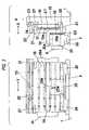
- FIG. 1is a plan view showing one preferred embodiment of an electronic components mounting apparatus of the invention
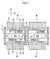
- FIG. 2is a cross-sectional view of the electronic components mounting apparatus of the invention
- FIG. 3is a view explanatory of the structure of a drive transmission portion of a moving beam of the electronic components mounting apparatus of the invention.
- FIG. 4is a cross-sectional view of the drive transmission portion of the moving beam of the electronic components mounting apparatus of the invention.
- a conveyer path 2is provided on a base 1 of the electronic components mounting apparatus, and extends in a direction X.
- the conveyer path 2transfers a board 3 on which electronic components are mounted, and this conveyer path 2 positions the board 3 in each of two stages S 1 and S 2 set on the conveyer path 2 .
- Each of the mounting stages S 1 and S 2comprises parts supply portions 4 , each having a plurality of juxtaposed parts feeders 5 , provided respectively at opposite sides thereof, and a mounting mechanism for taking electronic components from the parts-supply portions 4 and for mounting these parts on the board 3 .
- Two Y linear driving mechanisms 6are provided between the mounting stages S 1 and S 2 , and are disposed in a direction Y.
- the Y linear driving mechanism 6is driven by a linear motor as described later.
- This linear driving mechanismmoves X linear driving mechanisms 8 , each guided at opposite ends thereof by two guide rails 7 , in the direction Y.
- the X linear driving mechanism 8is driven by a linear motor, and this linear driving mechanism moves a mounting head 9 in the direction X.
- the mounting head 9is a multi-type mounting head having a plurality of unit mounting heads 9 a .
- Electronic componentsare suction-held respectively by suction nozzles 12 provided respectively at the unit mounting heads 9 a .
- the mounting head 9is provided with a board recognition camera 13 which is movable together with the mounting head 9 .
- the board recognition camera 13moves, together with the mounting head 9 , into a position above the board 3 , and recognizes the position of this board 3 .
- the mounting head 9When the Y linear driving mechanism 6 and the X linear driving mechanism 8 are driven, the mounting head 9 is moved in the directions X and Y, and the mounting head 9 picks up the electronic components from the parts feeders 5 of the parts supply portion 4 , and transfers the electronic components, and mounts them on the board 3 .
- a line camera 10 and a nozzle stocker 11are provided between the parts supply portion 4 and the conveyer path 2 .
- the mounting head 9which has taken the electronic components from the parts supply portion 4 , passes over the line camera 10 , the electronic components, held by the mounting head 9 , are recognized by this line camera 10 .
- the suction nozzles 12(corresponding respectively to the kinds of electronic components) which are to be attached to the mounting head 9 are stored in the nozzle stocker 11 , and when the mounting head 9 makes access to the nozzle stocker 11 , the suction nozzles 12 are automatically exchanged.
- the Y linear driving mechanism 6is provided in the electronic components-mounting apparatus used for mounting the electronic components on the board, and this Y linear driving mechanism 6 has the function of linearly moving the X linear driving mechanism 8 (which is a driven structure) in the direction Y (first direction) by the linear motor, and includes the drive transmission portion for transmitting a driving force of the linear motor to the X linear driving mechanism 8 .
- the guide rails 7 for guiding the X linear driving mechanism 8 in the direction Yare mounted on the base 1 .
- Sliders 26are slidably fitted on the guide rail 7 , and are fixed to a lower surface of a connecting member 25 connected to the X linear driving mechanism 8 .
- the guide rail 7 , the sliders 26 and the connecting member 25jointly serve as a guide portion for guiding the driven structure in the first direction.
- Reference numeral 15denotes a vertical bracket 15 which forms part of the Y linear driving mechanism, and this vertical bracket 15 is mounted in a vertical posture on the base 1 , and extends in the direction Y (the first direction).
- a stator 16 of the linear motor(which comprises this stator 16 and a moving element 17 opposed to the stator 16 ) is fixed to a side surface of the vertical bracket 15 .
- the vertical bracket 15serves as a stator holding portion which fixedly holds the stator 16 in the direction Y.
- the linear motorcomprising the stator 16 and the moving element 17 , is mounted in the direction Y in such a manner that the area of facing of the stator 16 and the moving element 17 each other is directed toward the driven structure (toward the X linear driving mechanism 8 ).
- a moving plate 18is connected to a rear surface of the moving element 17 (that is, that surface thereof facing away from the stator 16 ) through a spacer member 18 a , and a first gap G 1 which is equal to the thickness of the spacer member 18 a is formed between the moving element 17 and the moving plate 18 .
- the moving plate 18is mounted in such a manner that a second gap G 2 is formed between the moving plate 18 and the connecting member 25 .
- a flange portion 19formed on a rear surface of the moving plate 18 , is disposed in contact with an upper surface of the connecting member 25 .
- a projection 19 ais formed on a lower surface of the flange portion 19 , and this projection 19 a is fitted in a groove 25 a formed in the upper surface of the connecting member 25 .
- the projection 19 ais fitted in the groove 25 a in such a manner that a force to restrain the flange portion 19 and the connecting member 25 does not act in the direction X, and a restraining force acts only in the direction Y.
- a driving force of the moving element 17acts in the direction Y, but a force, applied from the moving element 17 to the flange portion 19 , will not be transmitted to the connecting member 25 as described later.
- the flange portion 19 and the connecting member 25are connected to the moving element 17 , and serve as the drive transmission portion for transmitting the driving force of the moving element 17 (acting in the direction Y) to the X linear driving mechanism 8 .
- This drive transmission portionis interposed between the moving element 17 and the X linear driving mechanism 8 , and is designed to transmit only the force acting in the direction Y.
- the drive transmission portionis not limited to the above construction, and any other suitable mechanism than the combination of the projection 19 a and the groove 25 a can be adopted in so far as the restraining force does not act in the direction X, but acts only in the direction Y.
- a plurality of guide rollers 21are mounted at upper and lower end portions of the moving plate 18 in such a manner that axes of these guide rollers 21 are disposed vertically.
- the guide rollers 21are held in contact with corresponding guide rails 20 mounted on the side surface of the vertical bracket 15 and extending in the direction Y.
- the guide rollers 21roll along the corresponding guide rails 20 .
- a plurality of guide rollers 23are mounted on a plate member 22 , fixed to the upper end of the moving plate 18 , in such a manner that axes of these guide rollers 23 are disposed horizontally.
- a guide groove 24 in which the guide rollers 23 are fittedis formed in the upper end portion of the vertical bracket 15 , and extends in the direction Y.
- FIG. 4shows a condition in which an attractive force F due to a magnetic force is exerted between the moving element 17 and the stator 16 during the operation of the linear motor.
- This attractive force Fis supported by reaction forces R produced as a result of pressing of the guide rollers 21 against the guide rails 20 .
- the guide rails 20 and the guide rollers 21serve as an attractive force-supporting portion provided at the drive transmission portion so as to support the attractive force acting between the stator 16 and moving element 17 in the opposing direction.
- the attractive force Fwill not act on sliding portions of the guide rails 7 and sliders 26 , and even when the X linear driving mechanism 8 moves at high speed in the direction Y, these sliding portions will not operate under a heavy load, so that a long lifetime of the component parts can be secured.
- the moving element 17is always kept in a heated condition by a drive current. Therefore, heat is transferred from the moving element 17 to the moving plate 18 and the connecting portion 25 , and is further transferred to the X linear driving mechanism 8 , so that the temperature of this X linear driving mechanism rises.
- the structural members of the X linear driving mechanism 8are thermally expanded by this temperature rise, and then are thermally contracted when they are cooled, thus repeating the thermal expansion and contraction. This thermal expansion and contraction incur various troubles such as lowered precision of positioning of the mounting head 9 mounted on the X linear driving mechanism 8 .
- the first gap G 1is formed between the moving element 17 and the moving plate 18 , and the transfer of heat from the moving element 17 to the moving plate 18 is effected only via the spacer member 18 a . Therefore, the heat transfer is suppressed as compared with a construction in which the moving element 17 is disposed in direct contact with the moving plate 18 .
- the second gap G 2is formed between the moving plate 18 and the connecting member 25 , and therefore the transfer of heat from the moving plate to the connecting member 25 is also suppressed.
- the Y linear driving mechanism 6has been described, a similar construction is applied to the X linear driving mechanism 8 for moving the mounting head 9 .
- the direction Xis a first direction
- the mounting headis a driven structure or member.
- the electronic components mounting apparatus for mounting the electronic components on the boardis illustrated as the electronic components-mounting apparatus, the invention can be applied to a mounting apparatus forming an electronic components-mounting line, such as a screen printing apparatus.
- the linear driving mechanismprovided in the electronic components mounting apparatus of the invention, has an advantage that it can prevent the troubles caused by the thermal expansion and contraction due to the generation of heat from the linear motor, and is effectively used as the linear driving mechanism for linearly driving the driven member such as the mounting head mounted in the electronic components-mounting apparatus such as the electronic components mounting apparatus.
Landscapes
- Engineering & Computer Science (AREA)
- Physics & Mathematics (AREA)
- Chemical & Material Sciences (AREA)
- Combustion & Propulsion (AREA)
- Electromagnetism (AREA)
- Power Engineering (AREA)
- Manufacturing & Machinery (AREA)
- Microelectronics & Electronic Packaging (AREA)
- Supply And Installment Of Electrical Components (AREA)
- Linear Motors (AREA)
Abstract
Description
Claims (5)
Applications Claiming Priority (2)
| Application Number | Priority Date | Filing Date | Title |
|---|---|---|---|
| JP2003296064AJP4062210B2 (en) | 2003-08-20 | 2003-08-20 | Linear motion mechanism of electronic component mounting equipment |
| JP2003-296064 | 2003-08-20 |
Publications (2)
| Publication Number | Publication Date |
|---|---|
| US20050040713A1 US20050040713A1 (en) | 2005-02-24 |
| US7259483B2true US7259483B2 (en) | 2007-08-21 |
Family
ID=34191132
Family Applications (1)
| Application Number | Title | Priority Date | Filing Date |
|---|---|---|---|
| US10/922,664Expired - LifetimeUS7259483B2 (en) | 2003-08-20 | 2004-08-20 | Linear driving mechanism of electronic components mounting apparatus |
Country Status (6)
| Country | Link |
|---|---|
| US (1) | US7259483B2 (en) |
| JP (1) | JP4062210B2 (en) |
| KR (1) | KR101042592B1 (en) |
| CN (1) | CN100506008C (en) |
| DE (1) | DE112004001534T5 (en) |
| WO (1) | WO2005020658A1 (en) |
Cited By (9)
| Publication number | Priority date | Publication date | Assignee | Title |
|---|---|---|---|---|
| US20050257638A1 (en)* | 2004-04-23 | 2005-11-24 | Matsushita Electric Industrial Co., Ltd. | Linear driving mechanism and electronic component mounting apparatus using the same |
| US20090206693A1 (en)* | 2007-05-09 | 2009-08-20 | David Gregory Calley | Electrical output generating devices and driven electrical devices having tape wound core laminate rotor or stator elements, and methods of making and use thereof |
| US20110050010A1 (en)* | 2008-11-03 | 2011-03-03 | Motor Excellence Llc | Transverse and/or commutated flux system stator concepts |
| US8053944B2 (en) | 2010-03-15 | 2011-11-08 | Motor Excellence, Llc | Transverse and/or commutated flux systems configured to provide reduced flux leakage, hysteresis loss reduction, and phase matching |
| US8222786B2 (en) | 2010-03-15 | 2012-07-17 | Motor Excellence Llc | Transverse and/or commutated flux systems having phase offset |
| US8395291B2 (en) | 2010-03-15 | 2013-03-12 | Electric Torque Machines, Inc. | Transverse and/or commutated flux systems for electric bicycles |
| US8405275B2 (en) | 2010-11-17 | 2013-03-26 | Electric Torque Machines, Inc. | Transverse and/or commutated flux systems having segmented stator laminations |
| US8836196B2 (en) | 2010-11-17 | 2014-09-16 | Electric Torque Machines, Inc. | Transverse and/or commutated flux systems having segmented stator laminations |
| US8952590B2 (en) | 2010-11-17 | 2015-02-10 | Electric Torque Machines Inc | Transverse and/or commutated flux systems having laminated and powdered metal portions |
Families Citing this family (3)
| Publication number | Priority date | Publication date | Assignee | Title |
|---|---|---|---|---|
| WO2013145180A1 (en)* | 2012-03-28 | 2013-10-03 | 富士機械製造株式会社 | Electrostatic-coupling-type non-contact power supplying device |
| DE102012025425B4 (en)* | 2012-12-21 | 2017-12-14 | Mimot Gmbh | Device for equipping substrates with electrical components |
| JP6011557B2 (en)* | 2014-01-31 | 2016-10-19 | 株式会社デンソー | Drive device |
Citations (6)
| Publication number | Priority date | Publication date | Assignee | Title |
|---|---|---|---|---|
| US5994799A (en)* | 1998-02-25 | 1999-11-30 | Siemens Aktiengesellschaft | Positioning apparatus for a positioning head |
| DE19857331C1 (en) | 1998-12-11 | 2001-01-25 | Siemens Ag | Cooling device for automatic placement machines |
| JP2001169529A (en)* | 1999-12-06 | 2001-06-22 | Shinko Electric Co Ltd | Mobile body and mobile body system |
| EP1246520A2 (en) | 2001-03-30 | 2002-10-02 | Sanyo Electric Co., Ltd. | Electronic component mounting apparatus |
| WO2004004100A1 (en)* | 2002-07-01 | 2004-01-08 | Thk Co., Ltd. | Drive guide device |
| US6724104B2 (en)* | 2000-09-29 | 2004-04-20 | Toshiba Kikai Kabushiki Kaisha | Linear motor drive apparatus |
Family Cites Families (1)
| Publication number | Priority date | Publication date | Assignee | Title |
|---|---|---|---|---|
| JP4551014B2 (en) | 2001-03-30 | 2010-09-22 | 株式会社日立ハイテクインスツルメンツ | Electronic component mounting device |
- 2003
- 2003-08-20JPJP2003296064Apatent/JP4062210B2/ennot_activeExpired - Fee Related
- 2004
- 2004-08-13CNCNB2004800228084Apatent/CN100506008C/ennot_activeExpired - Fee Related
- 2004-08-13DEDE112004001534Tpatent/DE112004001534T5/ennot_activeWithdrawn
- 2004-08-13WOPCT/JP2004/011947patent/WO2005020658A1/ennot_activeCeased
- 2004-08-13KRKR1020067003359Apatent/KR101042592B1/ennot_activeExpired - Fee Related
- 2004-08-20USUS10/922,664patent/US7259483B2/ennot_activeExpired - Lifetime
Patent Citations (6)
| Publication number | Priority date | Publication date | Assignee | Title |
|---|---|---|---|---|
| US5994799A (en)* | 1998-02-25 | 1999-11-30 | Siemens Aktiengesellschaft | Positioning apparatus for a positioning head |
| DE19857331C1 (en) | 1998-12-11 | 2001-01-25 | Siemens Ag | Cooling device for automatic placement machines |
| JP2001169529A (en)* | 1999-12-06 | 2001-06-22 | Shinko Electric Co Ltd | Mobile body and mobile body system |
| US6724104B2 (en)* | 2000-09-29 | 2004-04-20 | Toshiba Kikai Kabushiki Kaisha | Linear motor drive apparatus |
| EP1246520A2 (en) | 2001-03-30 | 2002-10-02 | Sanyo Electric Co., Ltd. | Electronic component mounting apparatus |
| WO2004004100A1 (en)* | 2002-07-01 | 2004-01-08 | Thk Co., Ltd. | Drive guide device |
Cited By (19)
| Publication number | Priority date | Publication date | Assignee | Title |
|---|---|---|---|---|
| US7578054B2 (en)* | 2004-04-23 | 2009-08-25 | Panasonic Corporation | Linear driving mechanism for electronic component mounting apparatus |
| US20050257638A1 (en)* | 2004-04-23 | 2005-11-24 | Matsushita Electric Industrial Co., Ltd. | Linear driving mechanism and electronic component mounting apparatus using the same |
| US7973446B2 (en) | 2007-05-09 | 2011-07-05 | Motor Excellence, Llc | Electrical devices having tape wound core laminate rotor or stator elements |
| US20090206693A1 (en)* | 2007-05-09 | 2009-08-20 | David Gregory Calley | Electrical output generating devices and driven electrical devices having tape wound core laminate rotor or stator elements, and methods of making and use thereof |
| US8030819B2 (en) | 2008-11-03 | 2011-10-04 | Motor Excellence, Llc | Transverse and/or commutated flux system rotor concepts |
| US20110062723A1 (en)* | 2008-11-03 | 2011-03-17 | Motor Excellence, Llc | Polyphase transverse and/or commutated flux systems |
| US7994678B2 (en) | 2008-11-03 | 2011-08-09 | Motor Excellence, Llc | Polyphase transverse and/or commutated flux systems |
| US8008821B2 (en)* | 2008-11-03 | 2011-08-30 | Motor Excellence, Llc | Transverse and/or commutated flux system stator concepts |
| US20110050010A1 (en)* | 2008-11-03 | 2011-03-03 | Motor Excellence Llc | Transverse and/or commutated flux system stator concepts |
| US8242658B2 (en) | 2008-11-03 | 2012-08-14 | Electric Torque Machines Inc. | Transverse and/or commutated flux system rotor concepts |
| US8193679B2 (en) | 2008-11-03 | 2012-06-05 | Motor Excellence Llc | Polyphase transverse and/or commutated flux systems |
| US8222786B2 (en) | 2010-03-15 | 2012-07-17 | Motor Excellence Llc | Transverse and/or commutated flux systems having phase offset |
| US8053944B2 (en) | 2010-03-15 | 2011-11-08 | Motor Excellence, Llc | Transverse and/or commutated flux systems configured to provide reduced flux leakage, hysteresis loss reduction, and phase matching |
| US8395291B2 (en) | 2010-03-15 | 2013-03-12 | Electric Torque Machines, Inc. | Transverse and/or commutated flux systems for electric bicycles |
| US8760023B2 (en)* | 2010-03-15 | 2014-06-24 | Electric Torque Machines, Inc. | Transverse and/or commutated flux systems having phase offset |
| US8405275B2 (en) | 2010-11-17 | 2013-03-26 | Electric Torque Machines, Inc. | Transverse and/or commutated flux systems having segmented stator laminations |
| US8836196B2 (en) | 2010-11-17 | 2014-09-16 | Electric Torque Machines, Inc. | Transverse and/or commutated flux systems having segmented stator laminations |
| US8854171B2 (en) | 2010-11-17 | 2014-10-07 | Electric Torque Machines Inc. | Transverse and/or commutated flux system coil concepts |
| US8952590B2 (en) | 2010-11-17 | 2015-02-10 | Electric Torque Machines Inc | Transverse and/or commutated flux systems having laminated and powdered metal portions |
Also Published As
| Publication number | Publication date |
|---|---|
| US20050040713A1 (en) | 2005-02-24 |
| CN100506008C (en) | 2009-06-24 |
| JP4062210B2 (en) | 2008-03-19 |
| KR20060065705A (en) | 2006-06-14 |
| WO2005020658A1 (en) | 2005-03-03 |
| KR101042592B1 (en) | 2011-06-20 |
| DE112004001534T5 (en) | 2006-06-14 |
| JP2005064418A (en) | 2005-03-10 |
| CN1833478A (en) | 2006-09-13 |
Similar Documents
| Publication | Publication Date | Title |
|---|---|---|
| US7259483B2 (en) | Linear driving mechanism of electronic components mounting apparatus | |
| US8823220B2 (en) | Positioning system for positioning a positioning unit along a longitudinal axis | |
| US20060236530A1 (en) | Device for assembling substrates with electronic components | |
| US5501388A (en) | Wire bonding apparatus | |
| JP4270019B2 (en) | Linear motion mechanism of electronic component mounting equipment | |
| JP4039342B2 (en) | Linear motion mechanism of electronic component mounting equipment | |
| EP1246519B1 (en) | Electronic component mounting apparatus | |
| US6796022B2 (en) | Electronic component mounting apparatus | |
| CN102548387A (en) | Component Mounting Device | |
| JPH11126996A (en) | Component mounting equipment | |
| JP4096837B2 (en) | Linear motion mechanism of electronic component mounting equipment | |
| US20060182585A1 (en) | Method and apparatus for mounting components | |
| JP4551014B2 (en) | Electronic component mounting device | |
| KR102865183B1 (en) | Stage for bonding die | |
| JP6126796B2 (en) | Electronic component mounting device | |
| JP4207833B2 (en) | Linear motion mechanism of electronic component mounting equipment | |
| JP2015015410A (en) | Component mounting device | |
| JP2002299892A (en) | Electronic component mounting device | |
| JP2005311104A (en) | Electronic component mounting equipment | |
| CN119789409A (en) | Novel chip mounter mounting head | |
| JP2005158924A (en) | Linear motion mechanism of electronic component mounting equipment | |
| JPH11307993A (en) | Mounting head | |
| JP2002299898A (en) | Electronic component mounting device | |
| JP2002299897A (en) | Electronic component mounting device |
Legal Events
| Date | Code | Title | Description |
|---|---|---|---|
| AS | Assignment | Owner name:MATSUSHITA ELECTRIC INDUSTRIAL CO., LTD., JAPAN Free format text:ASSIGNMENT OF ASSIGNORS INTEREST;ASSIGNORS:KOMIYA, TAKAHIRO;NAGAO, KAZUHIDE;REEL/FRAME:015721/0601 Effective date:20040728 | |
| FEPP | Fee payment procedure | Free format text:PAYOR NUMBER ASSIGNED (ORIGINAL EVENT CODE: ASPN); ENTITY STATUS OF PATENT OWNER: LARGE ENTITY | |
| STCF | Information on status: patent grant | Free format text:PATENTED CASE | |
| FEPP | Fee payment procedure | Free format text:PAYER NUMBER DE-ASSIGNED (ORIGINAL EVENT CODE: RMPN); ENTITY STATUS OF PATENT OWNER: LARGE ENTITY Free format text:PAYOR NUMBER ASSIGNED (ORIGINAL EVENT CODE: ASPN); ENTITY STATUS OF PATENT OWNER: LARGE ENTITY | |
| FPAY | Fee payment | Year of fee payment:4 | |
| FEPP | Fee payment procedure | Free format text:PAYOR NUMBER ASSIGNED (ORIGINAL EVENT CODE: ASPN); ENTITY STATUS OF PATENT OWNER: LARGE ENTITY Free format text:PAYER NUMBER DE-ASSIGNED (ORIGINAL EVENT CODE: RMPN); ENTITY STATUS OF PATENT OWNER: LARGE ENTITY | |
| FPAY | Fee payment | Year of fee payment:8 | |
| MAFP | Maintenance fee payment | Free format text:PAYMENT OF MAINTENANCE FEE, 12TH YEAR, LARGE ENTITY (ORIGINAL EVENT CODE: M1553); ENTITY STATUS OF PATENT OWNER: LARGE ENTITY Year of fee payment:12 |