US7258692B2 - Method and apparatus for reducing femoral fractures - Google Patents
Method and apparatus for reducing femoral fracturesDownload PDFInfo
- Publication number
- US7258692B2 US7258692B2US10/155,683US15568302AUS7258692B2US 7258692 B2US7258692 B2US 7258692B2US 15568302 AUS15568302 AUS 15568302AUS 7258692 B2US7258692 B2US 7258692B2
- Authority
- US
- United States
- Prior art keywords
- reamer
- retractor
- greater trochanter
- femoral
- guide tube
- Prior art date
- Legal status (The legal status is an assumption and is not a legal conclusion. Google has not performed a legal analysis and makes no representation as to the accuracy of the status listed.)
- Expired - Fee Related, expires
Links
Images


Classifications
- A—HUMAN NECESSITIES
- A61—MEDICAL OR VETERINARY SCIENCE; HYGIENE
- A61B—DIAGNOSIS; SURGERY; IDENTIFICATION
- A61B17/00—Surgical instruments, devices or methods
- A61B17/56—Surgical instruments or methods for treatment of bones or joints; Devices specially adapted therefor
- A61B17/58—Surgical instruments or methods for treatment of bones or joints; Devices specially adapted therefor for osteosynthesis, e.g. bone plates, screws or setting implements
- A61B17/88—Osteosynthesis instruments; Methods or means for implanting or extracting internal or external fixation devices
- A61B17/8875—Screwdrivers, spanners or wrenches
- A—HUMAN NECESSITIES
- A61—MEDICAL OR VETERINARY SCIENCE; HYGIENE
- A61B—DIAGNOSIS; SURGERY; IDENTIFICATION
- A61B17/00—Surgical instruments, devices or methods
- A61B17/16—Instruments for performing osteoclasis; Drills or chisels for bones; Trepans
- A61B17/164—Instruments for performing osteoclasis; Drills or chisels for bones; Trepans intramedullary
- A—HUMAN NECESSITIES
- A61—MEDICAL OR VETERINARY SCIENCE; HYGIENE
- A61B—DIAGNOSIS; SURGERY; IDENTIFICATION
- A61B17/00—Surgical instruments, devices or methods
- A61B17/16—Instruments for performing osteoclasis; Drills or chisels for bones; Trepans
- A61B17/1642—Instruments for performing osteoclasis; Drills or chisels for bones; Trepans for producing a curved bore
- A—HUMAN NECESSITIES
- A61—MEDICAL OR VETERINARY SCIENCE; HYGIENE
- A61B—DIAGNOSIS; SURGERY; IDENTIFICATION
- A61B17/00—Surgical instruments, devices or methods
- A61B17/16—Instruments for performing osteoclasis; Drills or chisels for bones; Trepans
- A61B17/1662—Instruments for performing osteoclasis; Drills or chisels for bones; Trepans for particular parts of the body
- A61B17/1664—Instruments for performing osteoclasis; Drills or chisels for bones; Trepans for particular parts of the body for the hip
- A61B17/1668—Instruments for performing osteoclasis; Drills or chisels for bones; Trepans for particular parts of the body for the hip for the upper femur
- A—HUMAN NECESSITIES
- A61—MEDICAL OR VETERINARY SCIENCE; HYGIENE
- A61B—DIAGNOSIS; SURGERY; IDENTIFICATION
- A61B17/00—Surgical instruments, devices or methods
- A61B17/16—Instruments for performing osteoclasis; Drills or chisels for bones; Trepans
- A61B17/17—Guides or aligning means for drills, mills, pins or wires
- A61B17/1739—Guides or aligning means for drills, mills, pins or wires specially adapted for particular parts of the body
- A61B17/1742—Guides or aligning means for drills, mills, pins or wires specially adapted for particular parts of the body for the hip
- A61B17/175—Guides or aligning means for drills, mills, pins or wires specially adapted for particular parts of the body for the hip for preparing the femur for hip prosthesis insertion
- A—HUMAN NECESSITIES
- A61—MEDICAL OR VETERINARY SCIENCE; HYGIENE
- A61B—DIAGNOSIS; SURGERY; IDENTIFICATION
- A61B17/00—Surgical instruments, devices or methods
- A61B17/56—Surgical instruments or methods for treatment of bones or joints; Devices specially adapted therefor
- A61B17/58—Surgical instruments or methods for treatment of bones or joints; Devices specially adapted therefor for osteosynthesis, e.g. bone plates, screws or setting implements
- A61B17/68—Internal fixation devices, including fasteners and spinal fixators, even if a part thereof projects from the skin
- A61B17/74—Devices for the head or neck or trochanter of the femur
- A61B17/742—Devices for the head or neck or trochanter of the femur having one or more longitudinal elements oriented along or parallel to the axis of the neck
- A—HUMAN NECESSITIES
- A61—MEDICAL OR VETERINARY SCIENCE; HYGIENE
- A61B—DIAGNOSIS; SURGERY; IDENTIFICATION
- A61B17/00—Surgical instruments, devices or methods
- A61B17/56—Surgical instruments or methods for treatment of bones or joints; Devices specially adapted therefor
- A61B17/58—Surgical instruments or methods for treatment of bones or joints; Devices specially adapted therefor for osteosynthesis, e.g. bone plates, screws or setting implements
- A61B17/88—Osteosynthesis instruments; Methods or means for implanting or extracting internal or external fixation devices
- A61B17/8802—Equipment for handling bone cement or other fluid fillers
- A61B17/8805—Equipment for handling bone cement or other fluid fillers for introducing fluid filler into bone or extracting it
- A—HUMAN NECESSITIES
- A61—MEDICAL OR VETERINARY SCIENCE; HYGIENE
- A61B—DIAGNOSIS; SURGERY; IDENTIFICATION
- A61B17/00—Surgical instruments, devices or methods
- A61B17/56—Surgical instruments or methods for treatment of bones or joints; Devices specially adapted therefor
- A61B17/58—Surgical instruments or methods for treatment of bones or joints; Devices specially adapted therefor for osteosynthesis, e.g. bone plates, screws or setting implements
- A61B17/88—Osteosynthesis instruments; Methods or means for implanting or extracting internal or external fixation devices
- A61B17/8863—Apparatus for shaping or cutting osteosynthesis equipment by medical personnel
- A—HUMAN NECESSITIES
- A61—MEDICAL OR VETERINARY SCIENCE; HYGIENE
- A61B—DIAGNOSIS; SURGERY; IDENTIFICATION
- A61B17/00—Surgical instruments, devices or methods
- A61B17/16—Instruments for performing osteoclasis; Drills or chisels for bones; Trepans
- A61B17/1613—Component parts
- A61B17/1615—Drill bits, i.e. rotating tools extending from a handpiece to contact the worked material
- A—HUMAN NECESSITIES
- A61—MEDICAL OR VETERINARY SCIENCE; HYGIENE
- A61B—DIAGNOSIS; SURGERY; IDENTIFICATION
- A61B17/00—Surgical instruments, devices or methods
- A61B17/16—Instruments for performing osteoclasis; Drills or chisels for bones; Trepans
- A61B17/1613—Component parts
- A61B17/1631—Special drive shafts, e.g. flexible shafts
- A—HUMAN NECESSITIES
- A61—MEDICAL OR VETERINARY SCIENCE; HYGIENE
- A61B—DIAGNOSIS; SURGERY; IDENTIFICATION
- A61B17/00—Surgical instruments, devices or methods
- A61B17/16—Instruments for performing osteoclasis; Drills or chisels for bones; Trepans
- A61B17/17—Guides or aligning means for drills, mills, pins or wires
- A61B17/1735—Guides or aligning means for drills, mills, pins or wires for rasps or chisels
- A—HUMAN NECESSITIES
- A61—MEDICAL OR VETERINARY SCIENCE; HYGIENE
- A61B—DIAGNOSIS; SURGERY; IDENTIFICATION
- A61B17/00—Surgical instruments, devices or methods
- A61B17/56—Surgical instruments or methods for treatment of bones or joints; Devices specially adapted therefor
- A61B17/58—Surgical instruments or methods for treatment of bones or joints; Devices specially adapted therefor for osteosynthesis, e.g. bone plates, screws or setting implements
- A61B17/68—Internal fixation devices, including fasteners and spinal fixators, even if a part thereof projects from the skin
- A61B17/70—Spinal positioners or stabilisers, e.g. stabilisers comprising fluid filler in an implant
- A61B17/7097—Stabilisers comprising fluid filler in an implant, e.g. balloon; devices for inserting or filling such implants
- A—HUMAN NECESSITIES
- A61—MEDICAL OR VETERINARY SCIENCE; HYGIENE
- A61B—DIAGNOSIS; SURGERY; IDENTIFICATION
- A61B17/00—Surgical instruments, devices or methods
- A61B17/00234—Surgical instruments, devices or methods for minimally invasive surgery
- A61B2017/00238—Type of minimally invasive operation
- A—HUMAN NECESSITIES
- A61—MEDICAL OR VETERINARY SCIENCE; HYGIENE
- A61B—DIAGNOSIS; SURGERY; IDENTIFICATION
- A61B17/00—Surgical instruments, devices or methods
- A61B17/00234—Surgical instruments, devices or methods for minimally invasive surgery
- A61B2017/00287—Bags for minimally invasive surgery
- A—HUMAN NECESSITIES
- A61—MEDICAL OR VETERINARY SCIENCE; HYGIENE
- A61B—DIAGNOSIS; SURGERY; IDENTIFICATION
- A61B17/00—Surgical instruments, devices or methods
- A61B2017/00535—Surgical instruments, devices or methods pneumatically or hydraulically operated
- A61B2017/00557—Surgical instruments, devices or methods pneumatically or hydraulically operated inflatable
- A—HUMAN NECESSITIES
- A61—MEDICAL OR VETERINARY SCIENCE; HYGIENE
- A61B—DIAGNOSIS; SURGERY; IDENTIFICATION
- A61B17/00—Surgical instruments, devices or methods
- A61B17/16—Instruments for performing osteoclasis; Drills or chisels for bones; Trepans
- A61B2017/1602—Mills
- A—HUMAN NECESSITIES
- A61—MEDICAL OR VETERINARY SCIENCE; HYGIENE
- A61F—FILTERS IMPLANTABLE INTO BLOOD VESSELS; PROSTHESES; DEVICES PROVIDING PATENCY TO, OR PREVENTING COLLAPSING OF, TUBULAR STRUCTURES OF THE BODY, e.g. STENTS; ORTHOPAEDIC, NURSING OR CONTRACEPTIVE DEVICES; FOMENTATION; TREATMENT OR PROTECTION OF EYES OR EARS; BANDAGES, DRESSINGS OR ABSORBENT PADS; FIRST-AID KITS
- A61F2/00—Filters implantable into blood vessels; Prostheses, i.e. artificial substitutes or replacements for parts of the body; Appliances for connecting them with the body; Devices providing patency to, or preventing collapsing of, tubular structures of the body, e.g. stents
- A61F2/02—Prostheses implantable into the body
- A61F2/28—Bones
- A61F2002/2825—Femur
- A—HUMAN NECESSITIES
- A61—MEDICAL OR VETERINARY SCIENCE; HYGIENE
- A61F—FILTERS IMPLANTABLE INTO BLOOD VESSELS; PROSTHESES; DEVICES PROVIDING PATENCY TO, OR PREVENTING COLLAPSING OF, TUBULAR STRUCTURES OF THE BODY, e.g. STENTS; ORTHOPAEDIC, NURSING OR CONTRACEPTIVE DEVICES; FOMENTATION; TREATMENT OR PROTECTION OF EYES OR EARS; BANDAGES, DRESSINGS OR ABSORBENT PADS; FIRST-AID KITS
- A61F2/00—Filters implantable into blood vessels; Prostheses, i.e. artificial substitutes or replacements for parts of the body; Appliances for connecting them with the body; Devices providing patency to, or preventing collapsing of, tubular structures of the body, e.g. stents
- A61F2/02—Prostheses implantable into the body
- A61F2/30—Joints
- A61F2002/30001—Additional features of subject-matter classified in A61F2/28, A61F2/30 and subgroups thereof
- A61F2002/30316—The prosthesis having different structural features at different locations within the same prosthesis; Connections between prosthetic parts; Special structural features of bone or joint prostheses not otherwise provided for
- A61F2002/30535—Special structural features of bone or joint prostheses not otherwise provided for
- A61F2002/30581—Special structural features of bone or joint prostheses not otherwise provided for having a pocket filled with fluid, e.g. liquid
- A61F2002/30583—Special structural features of bone or joint prostheses not otherwise provided for having a pocket filled with fluid, e.g. liquid filled with hardenable fluid, e.g. curable in-situ
- A—HUMAN NECESSITIES
- A61—MEDICAL OR VETERINARY SCIENCE; HYGIENE
- A61F—FILTERS IMPLANTABLE INTO BLOOD VESSELS; PROSTHESES; DEVICES PROVIDING PATENCY TO, OR PREVENTING COLLAPSING OF, TUBULAR STRUCTURES OF THE BODY, e.g. STENTS; ORTHOPAEDIC, NURSING OR CONTRACEPTIVE DEVICES; FOMENTATION; TREATMENT OR PROTECTION OF EYES OR EARS; BANDAGES, DRESSINGS OR ABSORBENT PADS; FIRST-AID KITS
- A61F2210/00—Particular material properties of prostheses classified in groups A61F2/00 - A61F2/26 or A61F2/82 or A61F9/00 or A61F11/00 or subgroups thereof
- A61F2210/0085—Particular material properties of prostheses classified in groups A61F2/00 - A61F2/26 or A61F2/82 or A61F9/00 or A61F11/00 or subgroups thereof hardenable in situ, e.g. epoxy resins
Definitions
- the present inventionrelates to a method and apparatus for treating hip fractures, and, more particularly, to a method and apparatus for reducing femoral fractures utilizing a minimally invasive procedure.
- a side plate/hip screw combinationi.e., a bone plate affixed to a lateral aspect of the femur and having a hip screw operably connected thereto, with the hip screw extending into the femoral head.
- a side plate hip screwTo properly implant a side plate hip screw, a surgeon must dissect an amount of muscle to expose the femur and operably attach the bone plate and hip screw.
- the side plate hip screwrequires an incision of about 10-12 cm through the quadriceps to expose the femur. While this approach provides surgeons with an excellent view of the bone surface, the underlying damage to soft tissue, including muscle, e.g., the quadriceps can lengthen a patient's rehabilitation time after surgery.
- What is needed in the artis a method and apparatus for reducing a hip fracture without requiring incision of soft tissue, including, e.g., the quadriceps.
- the present inventionprovides an improved method and apparatus for reducing a hip fracture utilizing a minimally invasive procedure which does not require dissection of the quadriceps.
- a femoral implant in accordance with the present inventionachieves intramedullary fixation as well as fixation into the femoral head to allow for the compression needed for a femoral fracture to heal.
- the femoral implant of the present inventionallows for sliding compression of the femoral fracture.
- an incision aligned with the greater trochanteris made and the wound is developed to expose the greater trochanter.
- the size of the wound developed on the surfaceis substantially constant throughout the depth of the wound.
- the incision through which the femur is prepared and the implant is insertedmeasures about 2.5 centimeters (3.9 inches). Because the greater trochanter is not circumferentially covered with muscle, the incision can be made and the wound developed through the skin and fascia to expose the greater trochanter, without incising muscle, including, e.g., the quadriceps. After exposing the greater trochanter, novel instruments of the present invention are utilized to prepare a cavity in the femur extending from the greater trochanter into the femoral head and further extending from the greater trochanter into the intramedullary canal of the femur.
- a femoral implant in accordance with the present inventionis inserted into the aforementioned cavity in the femur.
- the femoral implantis thereafter secured in the femur, with portions of the implant extending into and being secured within the femoral head and portions thereof extending into and being secured within the femoral shaft.
- the portion of the implant extending into the femoral headis slidable relative to the portion of the implant extending into the femoral shaft.
- the femoral implant of the present inventionincludes a sealed bag having a fill tube positioned therein to provide access to the bag interior so that the implant bag can be filled with material, e.g., bone cement after implantation of the femoral implant within the cavity formed in the femur.
- the femoral implant of the present inventionfurther includes a lag screw tube placed within the bag of the femoral implant.
- the bag of the femoral implantis tightly secured to the exterior of the lag screw tube to prevent material injected into the bag from escaping the bag at any point at which the bag contacts the lag screw tube.
- the lag screw tubeis hollow and accommodates a lag screw or other fixation device to be advanced into and secured to the femoral head.
- the sealed bag of the femoral implant of the present inventioncan be, e.g., formed of various films and fabrics.
- the bag of the femoral implant of the present inventionis formed from an acrylic material. Because bone cement is an acrylic, if the implant bag is formed of an acrylic, the bag and the bone cement will achieve an intimate chemical bond.
- the bag structure of the implant of the presentcomprises a nested bag structure in which an inner bag is filled with a high strength material relative to an outer bag in which the inner bag is placed.
- the outer bag of this form of the present inventionis formed from and filled with a more bioresorbable material relative to the material of construction and fill material of the inner bag.
- the femoral implant of the present inventionis inserted through an access aperture formed in the greater trochanter and placed within the femoral cavity described hereinabove.
- the lag screw or other fixation deviceis thereafter advanced through the lag screw tube and into the cavity formed in the femoral head.
- the lag screw or other fixation deviceis then secured to the femoral head.
- the fill tubeis thereafter utilized to fill the femoral implant with, e.g., bone cement to fill the femoral cavity and provide intramedullary fixation and stabilization of the lag screw.
- bone cementis utilized in lieu of lag screw threads to secure a lag screw shaft of an implant of the present invention.
- the guides and reamers of the present inventionare designed to allow for formation of a femoral cavity from the greater trochanter across the femoral neck and into the femoral head as well as from the greater trochanter into the intramedullary canal, with the femoral cavity having exposed access thereto only over the greater trochanter
- the method and apparatus of the current inventionadvantageously allow for the treatment of a femoral hip fracture in a minimally invasive procedure, which hastens patient recovery.
- FIG. 1is a partial perspective view of a patient, with an incision made along the greater trochanter to allow for implantation of a femoral implant of the present invention
- FIG. 2is a partial perspective view illustrating insertion of a guide plate in accordance with the present invention
- FIG. 3is a partial perspective view illustrating a guide tube/retractor in accordance with the present invention inserted through the incision aligned with the greater trochanter and engaged with the guide plate;
- FIG. 4is an elevational view illustrating the use of an alignment device of the present invention to properly select the appropriate guide tube/retractor of the present invention
- FIG. 5is an elevational view illustrating the alignment guide of FIG. 4 properly aligned from the greater trochanter along the femoral neck to the femoral head;
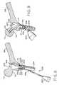
- FIG. 6is a sectional view of a femur illustrating a plunge reamer utilized to begin making the femoral cavity of the present invention
- FIG. 7is a sectional view illustrating the use of a swivel reamer in accordance with the present invention to further form the femoral cavity;
- FIG. 8is a sectional view illustrating further use of the swivel reamer depicted in FIG. 7 to form the femoral cavity;
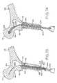
- FIG. 9is a sectional view illustrating the use of a curved femoral head reamer to extend the femoral cavity into the femoral head;
- FIG. 10is a sectional view illustrating the use of a curved femoral reamer to extend the femoral cavity into the intramedullary canal of the femur;
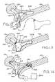
- FIG. 11is a sectional view illustrating a femoral cavity formed in accordance with the present invention.
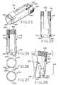
- FIG. 12is a sectional view illustrating insertion of a femoral implant of the present invention into the femoral cavity illustrated in FIG. 11 ;
- FIG. 13is a sectional view illustrating extension of the bag of the femoral implant into the intramedullary canal
- FIG. 14is a sectional view illustrating extension of a lag screw through the lag screw tube and into the femoral head, as well as a pump and source of bag fill, e.g., bone cement, utilized to fill the bag of the femoral implant of the present invention;
- bag fille.g., bone cement
- FIG. 15is a perspective view of a guide plate in accordance with the present invention.
- FIGS. 16 , 17 , and 18are, respectively, top, side, and bottom elevational views thereof;
- FIG. 19is a sectional view of an insertion member of the present invention with the guide plate illustrated in FIGS. 15-18 affixed thereto;
- FIG. 20is a perspective view of an insertion member which is utilized to operably position a guide plate, e.g., the guide plate illustrated in FIGS. 15-18 atop the greater trochanter as illustrated in FIG. 2 ;
- FIG. 21is a partial elevational view illustrating deactuation of the latch utilized to temporarily fix the guide plate to the insertion member
- FIG. 22is a side elevational view of the insertion member illustrated, e.g., in FIG. 20 ;
- FIG. 23is a perspective view of a guide tube/retractor of the present invention.
- FIG. 24is a radial elevational view thereof
- FIG. 25is a further radial elevational view thereof, rotated approximately 90 degrees with respect to the radial elevational view of FIG. 24 ;
- FIG. 26is a proximal axial view thereof
- FIG. 27is a distal axial view thereof
- FIG. 28is a radial elevational view of an angled guide tube/retractor of the present invention.
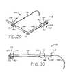
- FIG. 29is a perspective view of an alignment device of the present invention.
- FIG. 30is an elevational view thereof
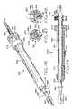
- FIG. 31is a perspective view of a plunge reamer of the present invention.
- FIG. 32is a distal axial view thereof
- FIG. 33is a partial sectional, elevational view thereof.
- FIG. 34is a perspective view of a swivel reamer of the present invention.
- FIG. 35is a proximal axial elevational view thereof
- FIG. 36is a sectional view taken along line 36 - 36 of FIG. 38 ;
- FIG. 37is a distal axial elevational view thereof
- FIG. 38is a partial sectional, elevational view of the swivel reamer of the present invention.
- FIG. 39is a perspective view of a curved femoral head reamer of the present invention.
- FIG. 40is a sectional view thereof
- FIG. 41is an elevational view of a femoral implant of the present invention.
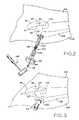
- FIG. 42is an exploded view of a lag screw of the present invention.
- FIG. 43is a sectional view of the femoral implant of the present invention taken along line 43 - 43 of FIG. 41 ;
- FIG. 44is a perspective view of an alternative embodiment alignment device of the present invention.
- FIG. 45is an elevational view thereof
- FIG. 46is a perspective view of a combination reamer in accordance with the present invention.
- FIG. 47is a sectional view thereof illustrating actuation of the swivel/plunge reaming selector into the plunge reaming position
- FIG. 48is a sectional view thereof with the swivel/plunge reaming selector moved into position for swivel reaming;
- FIG. 49is a partial sectional view of the combination reamer of the present invention.
- FIG. 50is a perspective view of an alternative embodiment guide plate in accordance with the present invention.
- FIGS. 51-54are top, end, side, and bottom elevational views thereof, respectively;
- FIG. 55is a sectional view thereof taken along line 55 - 55 of FIG. 53 ;
- FIG. 56is a perspective view of an alternative embodiment guide tube/retractor of the present invention.
- FIG. 57is a radial elevational view thereof
- FIG. 58is a radial elevational view of an alternative embodiment angled guide tube/retractor of the present invention.
- FIG. 59is a distal axial elevational view of the guide tube/retractor illustrated in FIG. 57 ;
- FIG. 60is a partial sectional view of the guide tube/retractor illustrated in FIG. 57 taken along line 60 - 60 thereof;
- FIG. 61is a perspective view of a fixation screw in accordance with an alternative embodiment of the present invention.
- FIG. 62is a radial elevational view thereof
- FIG. 63is a distal axial view thereof
- FIG. 64is a proximal axial view thereof
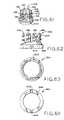
- FIG. 65is a perspective view of a second alternative embodiment guide plate in accordance with the present invention.
- FIG. 66is a top elevational view thereof
- FIG. 67is a sectional view thereof taken along line 67 - 67 of FIG. 66 ;
- FIG. 68is a bottom elevational view thereof
- FIG. 69is a perspective view of a second alternative embodiment guide tube/retractor in accordance with the present invention.
- FIG. 70is a radial elevational view thereof
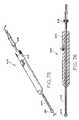
- FIG. 71is an exploded view of a flexible reamer guide in accordance with the present invention.
- FIG. 72is a sectional view thereof
- FIG. 73is a sectional view illustrating the flexible reamer guide of FIGS. 71 and 72 operably positioned within a patient's femur to guide a flexible reamer into the femoral head;
- FIG. 74is a sectional view illustrating a flexible reamer positioned over a flexible reamer guide wire for reaming into the femoral head;
- FIG. 75is a perspective view of a flexible reamer in accordance with the present invention.
- FIG. 76is a sectional view thereof
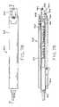
- FIG. 77is an exploded view of a flexible reamer guide wire bender in accordance with the present invention.
- FIG. 78is an elevational view thereof
- FIG. 79is a sectional view thereof
- FIG. 80is an axial view of the distal end of a fixation screw placement instrument in accordance with the present invention.
- FIG. 81is a perspective view of the fixation screw placement instrument partially illustrated in FIG. 80 ;
- FIG. 82is a perspective view of a straight reamer utilized to prepare the greater trochanter to receive the fixation screw illustrated in FIG. 61-64 ;
- FIG. 83is a perspective view of an alternative embodiment insertion member for inserting a guide plate of the present invention.
- FIG. 84is a partial sectional view thereof illustrating the release bars thereof actuated to effect release of the guide plate from locking engagement with the insertion member;
- FIG. 85is a partial sectional view illustrating the release bars of the insertion member illustrated in FIG. 83 positioned whereby the guide plate can be temporarily fixed to the insertion member;
- FIG. 86is an elevational view of the insertion member illustrated in FIG. 83 ;
- FIG. 87is a perspective view of a spring lock release instrument in accordance with the present invention.
- FIG. 88is a partial sectional view of the distal end thereof, illustrating the release pins in an unactuated position
- FIG. 89is a sectional view of the spring lock release instrument of FIG. 87 actuated to force release pins 346 to protrude therefrom;
- FIG. 90is an elevational view of an alternative embodiment femoral implant of the present invention.
- FIG. 91is a sectional view of an alternative embodiment lag screw of the present invention, illustrating insertion of an actuating device for actuating the lag screw head;
- FIG. 92is a partial sectional view of a further alternative embodiment lag screw of the present invention.
- Implant 260 illustrated in FIG. 41is utilized to reduce a femoral fracture utilizing a method of implantation which does not require incision of the quadriceps.
- incision 106is aligned with greater trochanter 110 , with femur 108 being prepared to receive implant 260 through incision 106 .
- greater trochanter 110is not covered with muscle and therefore, incision 106 can be developed to expose greater trochanter 110 without requiring the incision of muscle.
- various novel reamers of the present inventionare utilized to form femoral cavity 224 ( FIG. 11 ).
- implant 260(further illustrated in FIGS.
- lag screw 264is advanced into femoral head 114 until lag screw threads 282 firmly engage femoral head 114 and lag screw 264 has achieved the position illustrated in FIG. 14 .
- Bag 270is thereafter filled with material, e.g., bone cement to fill femoral cavity 224 and provide intramedullary fixation of implant 260 and stabilization of lag screw 264 . In this way, a femoral fracture including, e.g., an intertrochanteric fracture can be reduced.
- this documentwill refer to a femoral fracture and, specifically, to an intertrochanteric fracture.
- the method and apparatus of the present inventionis adaptable to various bone fractures including, e.g., supracondylar fractures of the femur.
- FIG. 1generally illustrates patient 100 including torso 102 , and legs 104 .
- FIG. 1further illustrates the general bone structures comprising the hip joint including, pubis 122 , anterior superior iliac spine 118 , ilium 116 , acetabulum 120 , and femur 108 .
- femur 108includes, e.g., greater trochanter 110 , femoral neck 112 , and femoral head 114 .
- incision 106is aligned with greater trochanter 110 . Because greater trochanter 110 is not covered with muscle, incision 106 can be made and the wound developed through the skin and fascia to expose greater trochanter 110 without incising muscle, including, e.g., the quadriceps.
- cannulated insertion member 124is utilized to insert guide plate 126 through incision 106 to be placed atop and secured to greater trochanter 110 as illustrated, e.g., in FIG. 2 .
- stabilization nail 144is positioned through elongate aperture 132 of insertion member 124 and impaction instrument 148 ( FIG. 2 ) is utilized to strike impaction surface 146 to drive stabilization nail 144 into femur 108 to provide initial stability to guide plate 126 prior to utilizing screws 128 ( FIG. 1 ) to fix guide plate 126 to greater trochanter 110 .
- the surgeon implanting guide plate 126will utilize a fluoroscope to verify proper placement of guide plate 126 atop greater trochanter 110 .
- the surgeon implanting guide plate 126will utilize tactile feedback either alone or in conjunction with a fluoroscope image to determine proper placement of guide plate 126 atop greater trochanter 110 .
- screws 128are driven through corresponding screw apertures 286 ( FIG. 15 ) in guide plate 126 and into femur 108 to secure guide plate 126 to femur 108 .
- Screw apertures 286are, in an exemplary embodiment, formed in guide plate 126 to allow for oblique insertion of screws 128 relative to guide plate 126 .
- Insertion member 124is illustrated in detail in FIGS. 19-22 .
- Insertion member 124includes elongate aperture 132 accommodating stabilization nail 144 as described hereinabove.
- Insertion member 124includes tubular latch connector 140 positioned about the distal end thereof. Intermediate the main body of insertion member 124 and tubular latch connector 140 is positioned spring 136 .
- Spring 136acts against spring stop 150 to bias tubular latch connector into the position illustrated in FIG. 22 .
- Release member 134is connected to tubular latch connector 140 and is operable to facilitate movement of tubular latch connector 140 against the biasing force of spring 136 into the position illustrated in FIG. 21 .
- Insertion member 124includes distal end 142 for engaging guide plate 126 .
- Distal end 142includes bosses 152 extending therefrom.
- Guide plate 126is temporarily affixed to insertion member 124 as described below. Bosses 152 enter attachment channels 290 of guide plate 126 (see, e.g., FIGS. 15 and 17 ). Concurrently latch 138 , connected to tubular latch connector 140 , acts against the proximal surface of guide plate 126 to force tubular latch connector 140 against the biasing force of spring 136 and into the position illustrated in FIG. 21 . Distal end 142 of insertion member 124 is then rotated until bosses 152 are positioned under lips 291 formed by attachment channels 290 and latch 138 can be positioned within one of attachment channels 290 and returned to its naturally biased position as illustrated in FIGS. 19 and 22 .
- bosses 152 and latch 138abut opposing radial extremes of one attachment channel 290 to prevent relative rotation of guide plate 126 and insertion number 124 .
- bosses 152cooperate with lips 291 formed by attachment channels 290 to prevent relative axial displacement of guide plate 126 and insertion member 124 . In this way, guide plate 126 is secured to insertion member 124 to facilitate positioning guide plate 126 atop greater trochanter 110 as described hereinabove.
- release member 134may be actuated to position latch 138 in the position illustrated in FIG. 21 to allow for rotation of distal end 142 of insertion member 124 .
- latch 138When latch 138 is positioned as illustrated in FIG. 21 , it is no longer contained within attachment channel 290 and therefore allows relative rotation between guide plate 126 and insertion member 124 .
- Distal end 142 of insertion member 124is rotated to reposition bosses 152 out of axial alignment with lips 291 for removal from attachment channels 290 . Insertion member 124 is thereafter removed from engagement with guide plate 126 and removed through incision 106 .
- guide tube/retractor 154is inserted through incision 106 and releasably fixed to guide plate 126 as illustrated in FIG. 3 .
- Guide tube/retractor 154is illustrated in detail in FIGS. 23-27
- guide plate 126is illustrated in detail in FIGS. 15-18 .
- FIGS. 23-27 and 15 - 18the cooperating apparatus of guide tube/retractor 154 and guide plate 126 allowing for selective locking of guide tube/retractor 154 to guide plate 126 will now be described.
- Fixation of guide tube/retractor 154 to guide plate 126is effected by first positioning attachment protrusions 302 of straight guide tube/retractor 154 into attachment channels 290 of guide plate 126 .
- Guide tube/retractor 154is then rotated clockwise to position the radially extending portion of attachment protrusions 302 under lips 291 formed by attachment channels 290 of guide plate 126 .
- spring biased locking pin 294 of guide tube/retractor 154is positioned within lock detent 292 of guide plate 126 to prevent relative rotation of guide plate 126 and guide tube/retractor 154 and lock guide tube/retractor 154 to guide plate 126 .
- spring biased locking pin 294extends substantially axially along guide tube/retractor 154 and is operably connected to actuation member 300 to provide for manual actuation of locking pin 294 .
- Spring 298is operatively associated with spring biased locking pin 294 and the interior of the cylindrical wall forming guide tube/retractor 154 to bias locking pin 294 into the position illustrated in FIG. 24 .
- angled guide tube/retractor 296is locked to guide plate 126 in the same manner utilizing the same structure as described above with respect to straight guide tube/retractor 154 .
- the shared components of straight guide tube/retractor 154 and angled guide tube/retractor 296are denoted with primed reference numerals.
- the mechanism for locking a guide tube/retractor of the present invention to guide plate 126allows for locking of a guide tube/retractor to guide plate 126 in one of two positions separated by 180 degrees. This allows for angled guide tube/retractor 296 to provide for realignment in two directions as will be further described hereinbelow.
- Guide tube/retractor 154serves the dual purpose of maintaining an access from incision 106 to greater trochanter 110 and guiding various instruments utilized to prepare femoral cavity 224 ( FIG. 11 ). Generally, either a straight or an angled guide tube/retractor will be utilized.
- FIGS. 24 and 28respectively illustrate straight guide tube/retractor 154 and angled guide tube/retractor 296 .
- angled guide tube/retractor 296includes distal end 299 and retractor body 301 . Longitudinal axis 297 of distal end 299 of angled guide tube/retractor 296 forms an angle ⁇ of about 10° with longitudinal axis 303 of retractor body 301 .
- angled guide tube/retractor 296allows for a 10° realignment with respect to straight guide tube/retractor 154 .
- the surgeonwill choose either straight guide tube/retractor 154 or angled guide tube/retractor 296 based upon the geometry of femur 108 into which implant 260 ( FIG. 41 ) will be placed.
- an alignment deviceis provided to facilitate choice of straight guide tube/retractor 154 or angled guide tube/retractor 296 as well as the orientation of angled guide tube/retractor 296 as further described hereinbelow.
- FIGS. 4 and 5illustrate use of alignment device 156 to choose either straight guide tube/retractor 154 or angled guide tube/retractor 296 .
- Alignment device 156is illustrated in detail in FIGS. 29 and 30 and includes extension 166 connected to transverse bar 168 , with alignment arm 174 slidably attached thereto. As illustrated in FIG. 29 , extension 166 is connected to insertion member 160 at a distal end thereof. Insertion member 160 is sized for insertion into either straight guide tube/retractor 154 or angled guide tube/retractor 296 as illustrated in FIGS. 4 and 5 .
- insertion portion 160 of alignment device 156includes distal end 158 connected via connecting rods 184 to positioning cylinder 164 .
- Positioning cylinder 164includes a pair of opposing bosses 162 , only one of which is depicted in FIGS. 29 and 30 .
- Distal end 158 and positioning cylinder 164have external geometries sized to cooperate with the hollow interior of the guide tube/retractors of the present invention to provide a stationary base for alignment device 156 , as illustrated in FIGS. 4 and 5 .
- Insertion portion 160 of alignment device 156as illustrated in FIGS.
- insertion portion 160will include a portion thereof having an exterior geometry sized to cooperate with the interior of the guide tube/retractors of the present invention to provide a stationary base for alignment device 156 .
- the insertion portion of alignment device 156 depicted in FIGS. 29 and 30comprises a solid insertion member having a consistent cross sectional area along its length.
- the exterior of the solid insertion memberwill cooperate with the interior of the guide tube/retractors of the present invention to provide a stable connection of alignment device 156 with a guide tube/retractor in accordance with the present invention.
- Alignment device 156includes transverse bar 168 fixed to extension 166 via screw 170 . Positioning cylinder 164 and extension 166 provide a stable base for transverse bar 168 . As illustrated in FIGS. 29 and 30 , alignment arm 174 is slidably connected to transverse bar 168 via slidable attachment member 176 . Slidable attachment member 176 includes attachment block 178 having a cutout therein accommodating transverse bar 168 . Top plate 180 is mounted atop attachment block 178 , with set screw 172 threaded therein. Set screw 172 traverses top plate 180 to selectively engage transverse bar 168 and lock alignment arm 174 in position along transverse bar 168 .
- alignment device 156is utilized to facilitate selection of the appropriate guide tube/retractor.
- FIG. 5illustrates alignment device 156 operably positioned within straight guide tube/retractor 154 , which is locked to guide plate 126 .
- bosses 162 on positioning cylinder 164are positioned within attachment channels 290 of guide plate 156 and positioning cylinder 164 is rotated until bosses 162 contact the terminal ends of channels 290 and are positioned under lips 291 .
- slidable attachment member 176may be adjusted to accommodate the physiological characteristics of the patient and place alignment arm 174 adjacent the patient's skin.
- Alignment arm 174 of alignment device 156includes a curved distal end having a curvature based on statistical data which follows a path from the central portion of greater trochanter 110 , along the central axis of femoral neck 112 , to the central region of femoral head 114 .
- FIG. 5illustrates an arrangement with the distal end of alignment arm 174 following the aforementioned path on femur 108 .
- straight guide tube/retractor 154is the appropriate guide tube/retractor to be utilized to effect the method of the present invention.
- angled guide tube/retractor 296may be utilized in an attempt to provide the appropriate alignment with the femur in question.
- FIG. 4illustrates alignment device 156 utilized with angled guide tube/retractor 296 on femur 108 .
- femur 108illustrated, e.g., in FIGS. 4 and 5 has a geometry accommodating the use of straight guide tube/retractor 154 .
- FIG. 4is useful in illustrating a situation in which the distal end of alignment arm 174 does not follow a path from the central portion of greater trochanter 110 , along the central axis of femoral neck 112 to the central region of femoral head 114 and, therefore, use of the attached guide tube/retractor, i.e., angled guide tube/retractor 296 is contraindicated.
- Comparison of the distal end of alignment arm 174 to the aforementioned path from the central portion of the greater trochanter, along the central axis of the femoral neck to the central portion of the femoral headwill be effected during surgery with the use of a fluoroscope.
- straight guide tube/retractor 154will first be locked to guide plate 126 , and alignment device 156 will be operably positioned therein. A fluoroscope will then be utilized to compare the distal end of alignment arm 174 with the path from the central portion of the greater trochanter, along the central axis of the femoral neck to the central portion of the femoral head. If the distal end of alignment arm 174 does not follow the aforementioned path from the central portion of the greater trochanter to the central portion of the femoral head, then alignment device 156 and straight guide tube/retractor 154 will be removed and angled guide tube retractor 296 will be locked to guide plate 126 .
- the angle ⁇ of about 10° formed between longitudinal axis 297 of distal end 299 of angled guide tube/retractor 296 and longitudinal axis 303 of retractor body 301allows for an approximately 10 degree realignment on either side of the longitudinal axis of straight guide tube/retractor 154 in a plane substantially containing the central axis of femur 108 .
- the inventors of the current inventionhave found that this 10 degree realignment in either direction typically accounts for the various bone geometries encountered.
- the inventors of the present inventionfurther contemplate provision of additional angled guide tubes/retractors having an angle ⁇ as described hereinabove of other than 10 degrees.
- ⁇could measure 5°, 10°, or 15° to provide for increased versatility in performing the method of reducing a femoral fracture in accordance with the present invention.
- cavity 224( FIG. 11 ) can be formed in femur 108 .
- straight reamer 186is first positioned within guide tube/retractor 154 and utilized to create access 101 in greater trochanter 110 .
- access 101has a 1.9 centimeter (0.75 inch) diameter.
- straight reamer 186is removed from guide tube/retractor 154 and replaced with swivel reamer 202 as illustrated, e.g., in FIG. 7 . As illustrated in FIG.
- swivel reamer 202is rotatable about pivot 216 and, in the configuration illustrated in FIG. 7 , allows for the extension of femoral cavity 224 toward femoral head 114 .
- swivel reamer 202is repositioned to allow for extension of femoral cavity 224 toward the shaft of femur 108 as illustrated in FIG. 8 .
- Swivel reamer 202is then removed in favor of curved femoral head reamer 226 . As illustrated in FIG.
- curved femoral head reamer 226is advanced through access 101 into femoral head 114 , thus expanding femoral cavity 224 into femoral head 114 .
- Curved femoral head reamer 226is thereafter removed from guide tube/retractor 154 and replaced with curved femoral shaft reamer 244 , as illustrated in FIG. 10 .
- Curved femoral shaft reamer 244is positioned through access 101 into the intramedullary canal of femur 108 , as illustrated in FIG. 7 , to extend femoral cavity 224 into the femoral shaft.
- the reaming process illustrated in FIGS. 6-10produces femoral cavity 224 as illustrated, e.g., in FIG. 11 .
- Straight reamer 186is illustrated in detail in FIGS. 31-33 .
- straight reamer 186includes straight reamer guide tube 188 surrounding straight reamer shaft 192 .
- Straight reamer guide tube 188is positioned intermediate straight reamer head 190 and flange 194 and is operable to move along reamer shaft 192 therebetween.
- Straight reamer guide tube 188as an exterior geometry cooperating with the internal geometry of straight guide tube/retractor 154 and/or angled guide tube/retractor 296 to provide a solid base for reaming femur 108 as illustrated in FIG. 6 .
- Straight reamer 186further includes proximal end 198 adapted to be received in chuck 200 ( FIG.
- Straight reamer guide tube 188includes opposing bosses 196 protruding from the exterior surface thereof. Bosses 196 are engagable in boss channels 304 formed in the proximal end of the guide tube/retractors of the present invention (see, e.g., FIGS. 23 , 24 , and 28 ).
- straight reamer guide tube 188is positioned within a guide tube/retractor of the present invention, with bosses 196 entering boss channels 304 formed in a proximal end thereof.
- Guide tube 188is then rotated until bosses 196 are positioned beneath the lip formed by the proximal end of straight guide tube/retractor of the present invention covering the radially extending portions of boss channels 304 .
- guide tube 188cannot readily be axially displaced with respect to the guide tube/retractor into which it is inserted.
- Proximal end 198 of straight reamer 186is actuated to provide rotational movement of reamer head 190 to form access 101 in femur 108 .
- straight reamer 186is configured to provide a reaming depth of 1.9 centimeters (0.75 inches) into femur 108 .
- Swivel reamer 202is illustrated in detail in FIGS. 34-38 .
- swivel reamer 202includes swivel reamer guide tube 204 having opposing bosses 212 protruding therefrom.
- Swivel reamer guide tube 204includes cutout 210 operable to allow reamer shaft 208 to pivot about swivel reamer pivot 216 as further described hereinbelow and as illustrated in FIG. 38 .
- swivel reamer 202includes proximal end 214 operable to connect swivel reamer 202 to chuck 200 ( FIG. 7 ).
- Bosses 212are utilized to connect swivel reamer 202 to a guide tube/retractor of the present invention in the same manner as bosses 196 of straight reamer 186 .
- swivel reamer pivot 216is pivotally connected to swivel reamer guide tube 204 via pivot pins 218 .
- swivel reamer pivot 216is positioned about reamer shaft 218 and abuts enlarged portion 222 of swivel reamer shaft 208 and flange 220 on opposing axial ends thereof to prevent axial displacement of swivel reamer head 206 .
- the orientation of swivel reamer 202is changed 180 degrees to accommodate swivel reaming toward femoral head 114 as illustrated in FIG.
- the guide tube/retractor of the present inventionincludes opposing cut-outs 305 to accommodate swivel reaming toward femoral head 114 as illustrated in FIG. 7 as well as swivel reaming toward the femoral shaft as illustrated in FIG. 8 , without repositioning the guide tube/retractor.
- Curved femoral head reamer 226is illustrated in detail in FIGS. 39 and 40 .
- curved femoral head reamer 226includes guide tube 228 having bosses 236 protruding therefrom. Bosses 236 are utilized to position curved femoral head reamer 226 within guide tube/retractor of the present invention as described above with respect to straight reamer 186 and swivel reamer 202 .
- Curved femoral head reamer 226includes curved reamer shaft 232 having reamer head 230 operably connected to a distal end thereof.
- Proximal end 234 of curved reamer shaft 232is operable to connect curved reamer 226 to chuck 200 of an actuation device as illustrated in FIG. 9 .
- curved reamer shaft 232comprises a hollow shaft formed by outer tube 242 .
- Flexible driveshaft 240is positioned within outer tube 242 and allows for transmission of rotary motion from proximal end 234 of curved reamer 226 to reamer head 230 to effect reaming into femoral head 114 as illustrated in FIG. 9 .
- Guide tube 228 of curved femoral head reamer 226includes curved guide channel 238 for guiding movement of outer tube 242 of reamer shaft 232 as reamer head 230 is advanced into femoral head 114 as illustrated in FIG. 9 .
- Curved femoral shaft reamer 242is not illustrated in detail for the sake of brevity.
- Curved femoral shaft reamer 242has an identical structure to curved femoral head reamer 226 .
- the head of femoral shaft reamer 242is larger than the head of curved femoral head reamer 226 .
- the head of curved femoral head reamer 226may be larger than the head of curved femoral shaft reamer 242 .
- the radius of curvature of the reamer shaftsmay differ between curved femoral head reamer 226 and curved femoral shaft reamer 242 . In all cases, a tubular reamer shaft and flexible driveshaft is utilized.
- any remaining guide tube/retractor as well as guide plate 126is removed and implant 260 is positioned through access 101 to be implanted in femoral cavity 224 .
- retractorsare utilized to provide access from incision 106 to access 101 .
- bag 270( FIG. 41 ) is manipulated into a relatively small package positioned about lag screw tube 266 to be positioned through access 101 .
- bag 270is accordion folded. As further illustrated in FIG.
- fill tube 262 and reinforcement/expansion bar 268 of femoral implant 260are positioned adjacent lag screw tube 266 for positioning implant 260 through access 101 and into femoral cavity 224 .
- lag screw thread 282abuts the proximal end of femoral head arm 256 of implant cavity 224 as illustrated, e.g., in FIG. 13 .
- fill tube 262 and reinforcement/expansion bar 268can be manipulated into the operable position illustrated in FIG. 14 .
- bag 270extends into femoral shaft arm 258 of implant cavity 224 .
- a flexible drive deviceis utilized to advance lag screw 264 into femoral head 114 until reaching the terminal position illustrated in FIG. 14 .
- pump Pis utilized to convey a bag fill material for filling bag 270 from source of bag fill 284 through fill tube 262 .
- source of bag fill 284comprises a source of bone cement.
- Fill tube 264is formed to provide for retrograde filling of bag 270 .
- bag 270is filled with, e.g., bone cement, it expands to fill femoral cavity 224 , including, femoral shaft arm 258 thereof.
- the bag structure of the implant of the presentcomprises a nested bag structure in which an inner bag is filled with a high strength material relative to an outer bag in which the inner bag is placed.
- the outer bag of this form of the present inventionis formed from and filled with a more bioresorbable material relative to the material of construction and fill material of the inner bag.
- Implant 260is illustrated in detail in FIG. 41 .
- bag 270is secured to lag screw tube 266 to prevent material inserted into bag 270 from escaping between the contact points formed between bag 270 and lag screw tube 266 .
- reinforcement/expansion bar 268is positioned to facilitate deployment of implant 260 into femoral shaft arm 258 of femoral cavity 224 as described hereinabove. Reinforcement/expansion bar 268 will not be utilized in every embodiment of the present invention.
- reinforcement/expansion bar 268also functions to laterally spread bag 270 to facilitate placement of bone cement therein.
- fill tube 262is positioned within bag 270 , with bag 270 securely affixed to a proximal end thereof.
- FIG. 90illustrates alternative embodiment femoral implant 260 ′.
- Femoral implant 260 ′is generally identical to femoral implant 260 illustrated in FIG. 41 except for the provision of external fasteners 279 utilized to securely affix bag 270 ′ to lag screw tube 266 .
- femoral implant 260 ′will include a fill tube 262 ′ for filling bag 270 with bone cement.
- lag screw 264generally comprises curved lag screw shaft 274 rotatably connected to lag screw head 272 .
- lag screw shaft 274includes distal male threads 276 cooperating with proximal female threads 278 formed in lag screw head 272 .
- Mating threads 276 , 278are left handed threads.
- Lag screw head 272includes chamber 280 to accommodate distal threaded end 276 of lag screw shaft 274 when lag screw head 272 is operably positioned on lag screw shaft 274 .
- Lag screw head 272includes distal lag screw threads 282 for implanting lag screw 264 into femur 108 as described hereinabove.
- Cooperating threads 276 , 278are left handed threads, while lag screw threads 282 are right handed threads.
- lag screw head 272may be threadedly engaged on lag screw shaft 274 and, rotation of lag screw head 272 in a clockwise fashion to effect implantation of lag screw threads 282 into femur 108 will not cause lag screw head 272 to become separated from lag screw shaft 274 .
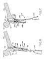
- FIG. 91illustrates an alternative embodiment lag screw 264 ′ in which lag screw head 272 includes flange 277 and lag screw shaft 274 includes bearing protrusion 275 .
- bearing protrusion 275is positioned intermediate the most proximal portion of lag screw head 272 ′ and flange 277 .
- flange 277cooperates with the most proximal portion of lag screw head 272 and bearing protrusion 275 to prohibit axial displacement of lag screw head 272 ′.
- Lag screw head 272 ′includes male hex 273 ′ operable for connection to flexible drive 281 as illustrated in FIG. 91 .
- flexible drive 281will be inserted within tubular lag screw shaft 274 and engaged with male hex 273 ′ to rotate lag screw head 272 to effect implantation thereof.
- lag screw shaft 274is similarly canulated to allow a flexible drive to enter lag screw shaft 274 and engage a cooperating protrusion (not shown) formed in lag screw head 272 .
- FIG. 92illustrates an alternative embodiment of lag screw head 272 ′′ wherein male threads 276 ′′ are formed on lag screw head 272 ′′, and female threads 278 ′ are formed in lag screw shaft 274 .
- guide plate 126 ′includes screw apertures 286 ′ for use in securing guide plate 126 to femur 108 as described hereinabove with respect to guide plate 126 .
- Guide plate 126 ′further includes spring pins 318 traversing axially oriented apertures in guide plate 126 ′. As illustrated in FIG. 55 , spring pins 318 engage alternate ends of springs 316 to hold springs 316 in position within guide plate 126 ′.
- guide plate 126 ′includes circular opening 322 as well as elliptical opening 324 , with springs 316 extending into circular opening 322 .
- springs 316are formed from titanium.
- guide plate 126 ′′includes axially oriented apertures accommodating spring pins 318 ′′ in much the same way as guide plate 126 ′ illustrated in FIGS. 50-55 .
- Spring pins 318 ′′are utilized to hold springs 316 ′′ in position within guide plate 126 ′′ as illustrated with respect to guide plate 126 ′ in FIG. 55 .
- Guide plate 126 ′′includes circular opening 322 ′′ as well as elliptical opening 324 ′′ similar to the corresponding openings found in guide plate 126 ′.
- the distal end of guide plate 126 ′′includes gripping teeth 404 formed therein.
- guide plate 126 ′′includes fixation screw shoulder 406 as illustrated, e.g., in FIG. 67 . Fization screw shoulder 406 will be further described hereinbelow.
- guide plate 126 ′is inserted through incision 106 for affixation to femur 108 in the same manner as guide plate 126 described hereinabove.
- Insertion member 124 ′ illustrated in FIGS. 83-86is utilized to position guide plate 126 ′ through incision 106 for placement atop greater trochanter 110 .
- insertion instrument 124 ′is similar to insertion instrument 124 illustrated in FIGS. 19-22 and further described hereinabove.
- insertion instrument 124 ′includes elongate aperture 132 ′ for accommodating stabilization nail 144 ( FIG. 2 ).
- Insertion member 124 ′includes release member 134 ′ connected via connecting rods 348 , and cylindrical connector 352 to release bars 350 . Release bars 350 travel in axially oriented slots formed in the distal end of insertion member 124 .
- the distal end of insertion member 124 ′includes elliptical protrusion 354 for placement within elliptical aperture 324 of guide plate 126 ′. Cooperation of elliptical protrusion 354 with elliptical aperture 324 insures proper rotational alignment of insertion member 124 ′ and guide plate 126 ′.
- insertion member 124 ′may be axially displaced into the central aperture of guide plate 126 ′, with springs 316 engaging spring slots 326 ′′ formed in opposing sides of the distal end of insertion member 124 ′. In this way, springs 316 lock guide plate 126 ′ to insertion member 124 ′. Bevel 317 facilitates positioning of springs 316 in spring slots 326 ′′.
- release bars 350are utilized to actuate springs 316 radially outwardly from their normally biased position to disengage spring slots 326 ′′ and allow for removal of insertion member 124 ′ from guide plate 126 ′.
- Release member 134 ′is utilized to effect axial displacement of release bars 350 from the position illustrated in FIG. 85 in which spring slots 326 ′′ are available for engagement with springs 316 to the position illustrated in FIG. 84 in which release bars 350 provide a radially outward force to springs 316 to allow for disengagement of insertion member 124 ′ from locking engagement with guide plate 126 ′ and allow for removal of insertion member 124 ′ through incision 106 .
- release bars 350include a distal bevel to facilitate movement from the position illustrated in FIG. 85 to the position illustrated in FIG. 84 to effect release of springs 316 from spring slots 326 ′′.
- insertion member 124 ′can be lockingly engaged with guide plate 126 ′′ illustrated in FIGS. 65-68 to effect implantation of guide plate 126 ′′ through incision 106 for placement atop greater trochanter 110 .
- plunge reamer 480When utilizing guide plate 126 ′′ illustrated in FIGS. 65-68 , plunge reamer 480 ( FIG. 82 ) must first be utilized to form a cavity in femur 108 extending through greater trochanter 110 .
- Plunge reamer 480includes reamer head 484 and flange 482 .
- plunge reamer 480is inserted through incision 106 and reamer head 484 is placed atop greater trochanter 110 .
- a fluoroscopemay be utilized to facilitate proper positioning of reamer head 484 atop greater trochanter 110 .
- a surgeonmay rely on tactile feedback for proper positioning of plunge reamer 480 .
- Plunge reamingis effected until flange 482 abuts greater trochanter 110 .
- Plunge reamer 480is thereafter removed through incision 106 to allow for placement of guide plate 126 ′′ atop greater trochanter 110 .
- Fixation screw 394 illustrated in FIGS. 61-64is thereafter utilized to secure guide plate 126 ′′ to greater trochanter 110 . While insertion instrument 124 ′ may be utilized to initially position guide plate 126 ′′ through incision 108 , it must be removed prior to implantation of fixation screw 394 .
- fixation screw 394includes fixation screw head 398 with fingers 396 axially depending therefrom. Screw threads 400 are formed on axially extending fingers 396 .
- the proximal end of fixation screw 394includes locking channel 402 , the utility of which will be further described hereinbelow.
- Fixation screw head 398forms a flange engagable with fixation screw shoulder 406 formed in guide plate 126 ′′ ( FIG. 67 ).
- Fixation screw 394is inserted through the central aperture of guide plate 126 ′′ and is screwed into the bore formed through greater trochanter 110 to secure guide plate 126 ′′ atop greater trochanter 110 . Threads 400 cut into the femoral bone stock to provide fixation of fixation screw 394 .
- Fixation screw placement instrument 470as illustrated in FIGS. 80 and 81 is utilized to insert fixation screw 394 through incision 106 and to secure fixation screw 394 within guide plate 126 ′′ as described hereinabove.
- fixation screw placement instrument 470includes a proximal handle as well as a distal end having blades 466 and ball detent 464 formed therein. In use, blades 466 engage locking channels 402 in fixation screw 394 , with ball detent 464 engaging a detent (not shown) formed in the inner diameter of locking screw 394 . The proximal handle of fixation screw placement instrument 470 may then be utilized to rotate fixation screw 394 and secure the same within femur 108 .
- guide tube/retractor 154 ′is utilized in lieu of guide tube/retractor 154 described hereinabove with reference to guide plate 126 .
- Guide tube/retractor 154 ′is illustrated in FIGS. 56 , 57 , 59 , and 60 .
- guide tube/retractor 154 ′includes a distal end having rounded portion 330 with spring slots 326 formed on opposing sides thereof.
- distal end of guide tube/retractor 154 ′includes engagement protrusions 328 having a radius of curvature matching the rounded ends of elliptical openings 324 and 324 ′′ in guide plates 126 ′ and 126 ′′, respectively.
- Opposing spring slots 326 formed in the distal end of guide tube/retractor 154 ′are utilized to selectively affix guide tube/retractor 154 ′ to either guide plate 126 ′ or 126 ′′ in the same fashion as described above with respect to insertion member 124 ′.
- angled guide tube/retractor 296 ′is provided for use with guide plates 126 ′ or 126 ′′.
- Angled guide tube/retractor 296 ′provides the same functionality as angled guide tube/retractor 296 described hereinabove with respect to guide plate 126 and includes a distal end identical to the distal end of straight guide tube/retractor 154 illustrated in FIGS. 56 , 57 , 59 , and 60 .
- Straight guide tube/retractor 154 ′ and angled guide tube/retractor 296 ′have a greater axial length than straight guide tube/retractor 154 and angled guide tube/retractor 296 described in the primary embodiment of the present invention.
- guide tube/retractors 154 ′ and 296 ′include latch channels 332 and 332 ′, respectively.
- latch channels 332 and 332 ′will be further described hereinbelow.
- alignment device 156 ′is utilized in conjunction with guide tube/retractors 154 ′, 296 ′ to select the appropriate guide tube/retractor as described hereinabove with respect to alignment device 156 .
- Alignment device 156 ′includes alignment guide tube 306 for positioning within guide tube/retractor 156 ′, or 296 ′ and providing a stable base for alignment device 156 ′ as described above with respect to insertion portion 160 of alignment device 156 ( FIGS. 29 and 30 ).
- Alignment guide tube 306includes latch 308 pivotally connected thereto via pivot pin 314 .
- alignment guide tube 306includes distal flat 386 which, in this exemplary embodiment will bottom out on the shoulder formed between the elliptical aperture and a round aperture in guide plates 126 ′ and 126 ′′.
- Latch 308includes oppositely depending locking tabs 310 extending from opposing sides thereof. Latch 308 is biased into the position illustrated in FIG. 45 by spring 312 . As alignment guide tube 306 is inserted into guide tube/retractor 156 ′ or 296 ′, locking tabs 310 contact the proximal end of guide tube/retractor 154 ′ or 296 ′.
- distal end of latch 308is depressed radially inwardly to move locking tabs 310 away from alignment guide tube 306 and allow for further insertion of alignment guide tube 306 into guide tube/retractor 154 ′ or 296 ′.
- distal flat 386bottoms out on the shoulder formed between the elliptical and the round apertures in guide plates 126 ′ and 126 ′′ when alignment guide tube 306 is fully inserted into guide tube/retractor 154 ′ or 296 ′.
- looking tabs 310 align with latch channels 332 and latch 308may be allowed to return to its normally biased position as illustrated in FIG. 45 .
- alignment device 156 ′is identical to alignment device 156 described above and is utilized in a similar fashion to choose between straight guide tube/retractor 154 ′ and angled guide tube/retractor 296 ′.
- Reaming of femoral cavity 224is effected with reamers having guide tubes and latches similar to guide tube 306 and latch 308 described above with respect to alignment device 156 ′.
- combination reamer 358 illustrated in FIGS. 46-49is utilized to effect both plunge, i.e., straight reaming into the femur as well as swivel reaming.
- combination reamer 358is inserted into guide tube/retractor 154 ′ or 296 ′, with orientation plate 384 cooperating with one of the longitudinal channels formed in guide tube/retractor 154 ′ or 296 ′ (see, e.g., FIGS.
- combination reamer 358includes reamer head 360 connected to the distal end of reamer shaft 362 .
- Reamer shaft 362includes flange 364 positioned toward the distal end thereof and ratchet teeth 382 formed toward the proximal end thereof.
- reamer shaft 362is positioned within reamer shaft tube 372 having reamer depth lock 374 formed on a proximal end thereof.
- Reamer depth lock 374includes ratchet release 376 connected via connecting rod 378 to ratchet head 380 as illustrated in FIG. 49 .
- FIG. 46illustrates the ability to properly align combination reamer 358 within the guide tube/retractor.
- combination reamer 358includes reamer head 360 connected to the distal end of reamer shaft 362 .
- Reamer shaft 362includes flange 364 positioned toward the distal end thereof and ratchet teeth 382 formed toward the proximal end thereof.
- reamer shaft 362is positioned within rea
- a springis utilized to bias ratchet head 380 into engagement with ratchet teeth 382 on reamer shaft 362 .
- Ratchet release 376is pivotally connected to reamer depth lock 374 such that actuation of ratchet release 376 causes outward radial movement of ratchet head 380 with respect to reamer shaft 362 , thus disengaging the ratchet teeth formed in ratchet head 380 with ratchet teeth 382 and allowing for relative axial movement of reamer shaft tube 372 and reamer shaft 362 .
- combination reamer 358can be utilized to effect plunge reaming, with the terminal reaming depth being reached when the distal end of reamer shaft tube 362 contacts pivot 216 .
- the overall depth of plunge reamingmay thus be adjusted by varying the axial displacement of reamer depth lock 374 along reamer shaft 362 .
- combination reamer 358includes combination reamer guide tube 366 having channel 368 formed therein.
- Swivel/plunge reaming selector 370is operably connected to a proximal end of combination reamer guide tube 366 .
- rotation guide pin 388is fixably secured to combination reamer guide tube 366 and positioned within rotation guide channel 390 of swivel/plunge reaming selector 370 .
- Swivel/plunge reaming selector 370may be rotated about guide tube 366 of combination reamer 358 between the extremes illustrated in FIGS. 47 and 48 , i.e. with rotation guide pin 388 in opposite ends of rotation guide channel 390 .
- swivel/plunge reaming selector 370When swivel/plunge reaming selector 370 is positioned as illustrated in FIG. 47 , swivel reaming with combination reamer 358 is not allowed because swivel/plunge reaming selector 370 covers channel 368 . To allow for swivel reaming, swivel/plunge reaming selector 370 is rotated into the position illustrated in FIG. 48 . In the position illustrated in FIG. 48 , channel 392 in swivel/plunge reaming selector 370 aligns with channel 368 in guide tube 366 of combination reamer 358 . In this position, swivel reaming can be effected as illustrated in FIG. 48 .
- Reamer shaft 362is connected to guide tube 366 of combination reamer 358 via pivot 216 ′ and pivot pins 218 ′ to allow for the swivel reaming illustrated in FIG. 48 .
- Combination reamer 358includes distal flat 386 ′ for signaling complete insertion of combination reamer 358 into reamer/guide tube 154 ′ or 296 ′. As described above with respect to alignment guide tube 306 of alignment device 156 ′, distal flat 386 ′ bottoms out on the shoulder formed between the elliptical and round apertures in guide plates 126 ′ and 126 ′′ when combination reamer 358 is fully inserted into guide tube/retractor 154 ′ or 296 ′.
- spring lock release instrument 336includes a tubular body sized for insertion into guide tube/retractor 156 ′ or 296 ′ with a distal shoulder indicating complete insertion of spring lock release instrument 336 into guide tube/retractor 156 ′ or 296 ′ in the manner described above with respect to alignment guide tube 306 of alignment device 156 ′, and combination reamer 358 .
- spring lock release instrument 336includes latch 308 ′ as described hereinabove with respect to guide tube 306 of alignment device 156 ′.
- handle 338is utilized to axially displace actuation rod 342 traversing internal aperture 344 of spring lock release instrument 336 into the position illustrated in FIG. 89 .
- the distal ramped end of actuation rod 342contacts the proximal ends of release pins 346 to overcome the biasing force of springs 347 ( FIG. 88 ) and cause release pins 346 to protrude from spring lock release instrument 336 as illustrated in FIG. 89 .
- release pins 346traverse apertures 155 , 155 ′ and act against springs 316 to disengage springs 316 from spring slots 326 and allow for removal of guide tube/retractor 154 ′ or 296 ′.
- release pins 346are spring biased.
- the inventors of the current inventioncontemplate that release pins 346 could be linked to actuation rod 346 via a mechanical linkage whereby pulling actuation rod 342 would pull pins 346 into the instrument and, conversely, pushing rod 342 would push the pins outwardly from the instrument.
- release pins 346are illustrated as forming an acute angle with the longitudinal axis of spring lock release instrument 336 , release pins 346 could be transversely positioned within spring lock release instrument 336 .
- Guide tube/retractor 156 ′′ in accordance with a further alternative embodiment of the present inventionis illustrated in FIGS. 69 and 70 .
- guide tube/retractor 154 ′′is configured for affixation directly to greater trochanter 110 , with guide plate 126 no longer being used.
- guide tube/retractor 154 ′′includes gripping teeth 404 ′′ formed in a distal end thereof.
- Gripping teeth 404 ′′are utilized to position guide tube/retractor 154 ′′ atop greater trochanter 110 and fixation screw 394 will be positioned within guide tube/retractor 154 ′′ and utilized to affix guide tube/retractor 154 ′′ to femur 108 as described above with reference to guide plate 126 ′′. While not illustrated in FIGS. 69 and 70 , guide tube/retractor 154 ′′ includes a shoulder for engaging screw head 398 of fixation screw 394 to complete fixation of guide tube/retractor 154 ′′ to femur 108 in the same manner as described above with respect to guide plate 126 ′′.
- flexible reamer 428 illustrated in FIGS. 75 and 76is utilized in lieu of the curved reamers described above to ream into femoral head 114 and into the shaft of femur 108 .
- flexible reamer 428includes reaming head 432 and flexible reaming shaft 434 .
- flexible reaming shaft 434is canulated, allowing for insertion of flexible reamer shaft 434 over a guide wire to guide reaming into femoral head 114 and into the shaft of the femur 108 .
- flexible reamer guide tube 430and a latch member associated with a particular reamer/guide tube of the present invention.
- flexible reamer 428may include various guide tubes having physical characteristics allowing for use of flexible reamer 428 with the various guide tube/retractors of the present invention.
- the proximal end of flexible reamer shaft 434is connected to flange 436 which acts against the proximal end of flexible reamer guide tube 430 to limit the reaming depth of flexible reamer 428 .
- flexible reamer guide 408( FIGS. 71 and 72 ) is utilized to position guide wire 410 within the femur to guide flexible reamer 428 .
- flexible reamer guide 408includes guide 416 having guide shaft fixation channel 412 formed therein.
- Guide 416is insertable within guide channel 420 of the main body of flexible reamer guide 408 as illustrated in FIG. 72 .
- Guide pegs 418depend from guide 416 and are further inserted within guide channel 420 as illustrated in FIG. 72 .
- Flexible reamer guide tube 486 of flexible reamer guide 408includes advance/retract screw aperture 488 and guide wire aperture 490 .
- guide wire 410is inserted in guide wire aperture 490 and positioned within guide shaft fixation channel 412 .
- Set screw 414is utilized to secure guide wire 410 within guide shaft fixation channel 412 .
- Advance/retract screw 422traverses a proximal aperture in guide 416 and advance/retract screw aperture 488 , and is threadably engaged with receiving block 426 as illustrated in FIG. 72 .
- Advance/retract screw 422includes flange 424 for abutting the proximal end of guide 416 and for forcing guide 416 to be distally displaced in flexible reamer guide tube 486 in response to distal movement of advance/retract screw 422 .
- Guide wire 410is formed from a memory metal such as, e.g., NITINOL.
- the advance retract screw 422may be retreated from receiving block 426 to allow guide wire 410 to retreat into guide wire aperture 490 to completely retract guide wire 410 within flexible reamer guide tube 486 of flexible reamer guide 408 , without losing the ability of guide wire 410 to regain the bent shape illustrated in FIG. 71 .
- flexible reamer guide 408is inserted within a guide tube/retractor of the present invention with guide wire 410 not protruding from the distal end of guide wire aperture 490 .
- the proximal end of advance retract screw 422is thereafter actuated to force guide 416 and, consequently, guide wire 410 through flexible reamer guide tube 486 and into femoral head 414 as illustrated in FIG. 73 .
- set screw 414may be removed and flexible reamer guide 408 removed from the guide tube/retractor, leaving guide wire 410 in place within femur 108 .
- Flexible reamer 428may then be operably inserted in guide tube/retractor 154 as illustrated in FIG.
- femoral cavity 224may be extended into femoral head 114 as illustrated in FIG. 74 , with flexible reamer 428 being guided by guide wire 410 .
- a similar techniquemay be utilized for advancing guide wire 410 into the femoral shaft to extend femoral cavity 224 therein.
- flexible reamer guide wire bender 440 as illustrated in FIGS. 77-79is utilized to in vivo bend a guide wire to guide reaming into, e.g., femoral head 114 as illustrated, e.g., in FIG. 73 .
- flexible reamer guide wire bender 440includes guide tube 456 for insertion into a guide tube/retractor of the present invention.
- Guide tube 456includes a pair of elongate apertures. A first of these apertures accommodates inner wire tube 450 and outer wire tube 452 as illustrated, e.g., in FIG. 79 .
- Wire shaping head 448is pivotally connected via pivot pin 444 to the distal end of flexible reamer guide wire bender 440 as illustrated in FIGS. 78 and 79 .
- roller 442is positioned about pivot pin 444 .
- Wire shaping head 448further includes roller pin 446 for connecting a second roller 442 in a rotatable manner to wire shaping head 448 .
- screws 454are utilized to affix the distal end of flexible reamer guide wire bender 440 to guide tube 456 .
- FIG. 77screws 454 are utilized to affix the distal end of flexible reamer guide wire bender 440 to guide tube 456 .
- outer wire tube 452includes proximal wire extreme 462 against which an end of a guide wire will abut.
- Outer wire tube 452is threadably engagable with either guide tube 456 or inner wire tube 450 so that outer wire tube 452 may be advanced into guide tube 456 to force a guide wire positioned against proximal wire extreme 462 through distal aperture 500 of flexible reamer guide wire bender 440 .
- Adjustment screw 458is utilized to rotate wire shaping head 448 about pivot pin 444 whereby rollers 442 bend a guide wire into the desired shape as it exits distal aperture 500 . Shaping of a guide wire in vivo with flexible reamer guide wire bender 440 may be observed with a fluoroscope.
- a guide wire bent with flexible reamer guide wire bender 440will be advanced into, e.g., femoral head 114 as illustrated, e.g., in FIG. 73 with respect to guide wire 410 .
- a flexible reamerwill be utilized to extend femoral cavity 224 toward the femoral head as illustrated in FIG. 74 .
- a similar proceduremay be utilized for extending femoral cavity 224 into the shaft of femoral 108 .
Landscapes
- Health & Medical Sciences (AREA)
- Life Sciences & Earth Sciences (AREA)
- Surgery (AREA)
- Orthopedic Medicine & Surgery (AREA)
- Medical Informatics (AREA)
- General Health & Medical Sciences (AREA)
- Biomedical Technology (AREA)
- Heart & Thoracic Surgery (AREA)
- Nuclear Medicine, Radiotherapy & Molecular Imaging (AREA)
- Molecular Biology (AREA)
- Animal Behavior & Ethology (AREA)
- Engineering & Computer Science (AREA)
- Public Health (AREA)
- Veterinary Medicine (AREA)
- Dentistry (AREA)
- Oral & Maxillofacial Surgery (AREA)
- Neurology (AREA)
- Surgical Instruments (AREA)
- Prostheses (AREA)
Abstract
Description
Claims (29)
Priority Applications (11)
| Application Number | Priority Date | Filing Date | Title |
|---|---|---|---|
| US10/155,683US7258692B2 (en) | 2000-03-07 | 2002-05-23 | Method and apparatus for reducing femoral fractures |
| US10/266,319US20030220646A1 (en) | 2002-05-23 | 2002-10-08 | Method and apparatus for reducing femoral fractures |
| US10/358,009US20030220644A1 (en) | 2002-05-23 | 2003-02-04 | Method and apparatus for reducing femoral fractures |
| AU2003204409AAU2003204409A1 (en) | 2002-05-23 | 2003-05-23 | Method and apparatus for reducing femoral fractures |
| EP03253269AEP1369089A3 (en) | 2002-05-23 | 2003-05-23 | Apparatus for reducing femoral fractures |
| CA002429758ACA2429758A1 (en) | 2002-05-23 | 2003-05-23 | Method and apparatus for reducing femoral fractures |
| JP2003146680AJP2004033756A (en) | 2002-05-23 | 2003-05-23 | Method and device for curing fractured thighbone |
| US11/061,898US7488329B2 (en) | 2000-03-07 | 2005-02-18 | Method and apparatus for reducing femoral fractures |
| US11/250,927US7485119B2 (en) | 2000-03-07 | 2005-10-14 | Method and apparatus for reducing femoral fractures |
| US11/611,194US20070123995A1 (en) | 2000-03-07 | 2006-12-15 | Method and apparatus for reducing femoral fractures |
| US11/754,517US20070225721A1 (en) | 2000-03-07 | 2007-05-29 | Method and apparatus for reducing femoral fractures |
Applications Claiming Priority (2)
| Application Number | Priority Date | Filing Date | Title |
|---|---|---|---|
| US09/520,351US6447514B1 (en) | 2000-03-07 | 2000-03-07 | Polymer filled hip fracture fixation device |
| US10/155,683US7258692B2 (en) | 2000-03-07 | 2002-05-23 | Method and apparatus for reducing femoral fractures |
Related Parent Applications (1)
| Application Number | Title | Priority Date | Filing Date |
|---|---|---|---|
| US09/520,351Continuation-In-PartUS6447514B1 (en) | 2000-03-07 | 2000-03-07 | Polymer filled hip fracture fixation device |
Related Child Applications (3)
| Application Number | Title | Priority Date | Filing Date |
|---|---|---|---|
| US10/266,319Continuation-In-PartUS20030220646A1 (en) | 2000-03-07 | 2002-10-08 | Method and apparatus for reducing femoral fractures |
| US10/266,313Continuation-In-PartUS6814787B2 (en) | 2000-12-22 | 2002-10-08 | Layered adsorption zone for hydrogen production swing adsorption |
| US11/754,517DivisionUS20070225721A1 (en) | 2000-03-07 | 2007-05-29 | Method and apparatus for reducing femoral fractures |
Publications (2)
| Publication Number | Publication Date |
|---|---|
| US20030220641A1 US20030220641A1 (en) | 2003-11-27 |
| US7258692B2true US7258692B2 (en) | 2007-08-21 |
Family
ID=29549140
Family Applications (2)
| Application Number | Title | Priority Date | Filing Date |
|---|---|---|---|
| US10/155,683Expired - Fee RelatedUS7258692B2 (en) | 2000-03-07 | 2002-05-23 | Method and apparatus for reducing femoral fractures |
| US11/754,517AbandonedUS20070225721A1 (en) | 2000-03-07 | 2007-05-29 | Method and apparatus for reducing femoral fractures |
Family Applications After (1)
| Application Number | Title | Priority Date | Filing Date |
|---|---|---|---|
| US11/754,517AbandonedUS20070225721A1 (en) | 2000-03-07 | 2007-05-29 | Method and apparatus for reducing femoral fractures |
Country Status (5)
| Country | Link |
|---|---|
| US (2) | US7258692B2 (en) |
| EP (1) | EP1369089A3 (en) |
| JP (1) | JP2004033756A (en) |
| AU (1) | AU2003204409A1 (en) |
| CA (1) | CA2429758A1 (en) |
Cited By (66)
| Publication number | Priority date | Publication date | Assignee | Title |
|---|---|---|---|---|
| US20060064098A1 (en)* | 2002-12-04 | 2006-03-23 | Henrik Hansson | Device at fixing means for fixation of bone fragments at bone fractures |
| US20070012816A1 (en)* | 2003-08-13 | 2007-01-18 | Thomas Kaup | Curved positioning and insertion instrument for inserting a guide wire into the femur |
| US20070093844A1 (en)* | 2005-10-12 | 2007-04-26 | Dye Donald W | Calcar planers for minimally invasive surgery |
| US20080269746A1 (en)* | 2007-04-24 | 2008-10-30 | Osteolign, Inc. | Conformable intramedullary implant with nestable components |
| US20080279941A1 (en)* | 2004-02-06 | 2008-11-13 | Georgia Tech Research Corporation | Method of treating joints with hydrogel implants |
| US20090192511A1 (en)* | 2008-01-28 | 2009-07-30 | Haffenreffer Mark E | Surgical instruments and instrument handle having support brace |
| US20100292695A1 (en)* | 2009-05-15 | 2010-11-18 | Zimmer, Inc. | Threaded, flexible implant and method for threading a curved hole |
| US20110015675A1 (en)* | 2009-07-16 | 2011-01-20 | Howmedica Osteonics Corp. | Suture anchor implantation instrumentation system |
| US20110060373A1 (en)* | 2009-09-09 | 2011-03-10 | Russell Thomas A | Bone screws and methods of use thereof |
| US7931689B2 (en) | 2000-02-28 | 2011-04-26 | Spineology Inc. | Method and apparatus for treating a vertebral body |
| US8128627B2 (en) | 2007-03-22 | 2012-03-06 | Sonoma Orthopedic Products, Inc. | Segmented intramedullary system and apparatus |
| US8210729B2 (en) | 2009-04-06 | 2012-07-03 | Illuminoss Medical, Inc. | Attachment system for light-conducting fibers |
| US8246628B2 (en) | 2006-04-26 | 2012-08-21 | Illuminoss Medical, Inc. | Apparatus for delivery of reinforcing materials to bone |
| US8287538B2 (en) | 2008-01-14 | 2012-10-16 | Conventus Orthopaedics, Inc. | Apparatus and methods for fracture repair |
| US8318192B2 (en) | 2004-02-06 | 2012-11-27 | Georgia Tech Research Corporation | Method of making load bearing hydrogel implants |
| US8348956B2 (en) | 2006-04-26 | 2013-01-08 | Illuminoss Medical, Inc. | Apparatus and methods for reinforcing bone |
| US8366711B2 (en) | 2006-11-10 | 2013-02-05 | Illuminoss Medical, Inc. | Systems and methods for internal bone fixation |
| US8403968B2 (en) | 2007-12-26 | 2013-03-26 | Illuminoss Medical, Inc. | Apparatus and methods for repairing craniomaxillofacial bones using customized bone plates |
| US8506476B1 (en)* | 2011-10-25 | 2013-08-13 | James Wright O'Mara, Jr. | Injection device for endoscopy |
| US8512338B2 (en) | 2009-04-07 | 2013-08-20 | Illuminoss Medical, Inc. | Photodynamic bone stabilization systems and methods for reinforcing bone |
| US8546456B2 (en) | 2008-07-25 | 2013-10-01 | Smith & Nephew, Inc. | Fracture fixation systems |
| US8684965B2 (en) | 2010-06-21 | 2014-04-01 | Illuminoss Medical, Inc. | Photodynamic bone stabilization and drug delivery systems |
| US8734460B2 (en) | 2006-11-10 | 2014-05-27 | Illuminoss Medical, Inc. | Systems and methods for internal bone fixation |
| US8821493B2 (en) | 2008-06-26 | 2014-09-02 | Smart Medical Devices, Inc. | Depth controllable and measurable medical driver devices and methods of use |
| US8821494B2 (en) | 2012-08-03 | 2014-09-02 | Howmedica Osteonics Corp. | Surgical instruments and methods of use |
| US8870965B2 (en) | 2009-08-19 | 2014-10-28 | Illuminoss Medical, Inc. | Devices and methods for bone alignment, stabilization and distraction |
| US8894654B2 (en) | 2010-03-31 | 2014-11-25 | Smart Medical Devices, Inc. | Depth controllable and measurable medical driver devices and methods of use |
| US8906022B2 (en) | 2010-03-08 | 2014-12-09 | Conventus Orthopaedics, Inc. | Apparatus and methods for securing a bone implant |
| US8936644B2 (en) | 2011-07-19 | 2015-01-20 | Illuminoss Medical, Inc. | Systems and methods for joint stabilization |
| US8939977B2 (en) | 2012-07-10 | 2015-01-27 | Illuminoss Medical, Inc. | Systems and methods for separating bone fixation devices from introducer |
| US8961518B2 (en) | 2010-01-20 | 2015-02-24 | Conventus Orthopaedics, Inc. | Apparatus and methods for bone access and cavity preparation |
| US9078740B2 (en) | 2013-01-21 | 2015-07-14 | Howmedica Osteonics Corp. | Instrumentation and method for positioning and securing a graft |
| US20150250506A1 (en)* | 2012-09-20 | 2015-09-10 | Hipco, Llc | Hip implant |
| US9144442B2 (en) | 2011-07-19 | 2015-09-29 | Illuminoss Medical, Inc. | Photodynamic articular joint implants and methods of use |
| US9155543B2 (en) | 2011-05-26 | 2015-10-13 | Cartiva, Inc. | Tapered joint implant and related tools |
| US9179959B2 (en) | 2010-12-22 | 2015-11-10 | Illuminoss Medical, Inc. | Systems and methods for treating conditions and diseases of the spine |
| US9232954B2 (en) | 2009-08-20 | 2016-01-12 | Howmedica Osteonics Corp. | Flexible ACL instrumentation, kit and method |
| US9402620B2 (en) | 2013-03-04 | 2016-08-02 | Howmedica Osteonics Corp. | Knotless filamentary fixation devices, assemblies and systems and methods of assembly and use |
| US9427289B2 (en) | 2007-10-31 | 2016-08-30 | Illuminoss Medical, Inc. | Light source |
| US9445803B2 (en) | 2011-11-23 | 2016-09-20 | Howmedica Osteonics Corp. | Filamentary suture anchor |
| US9463013B2 (en) | 2013-03-13 | 2016-10-11 | Stryker Corporation | Adjustable continuous filament structure and method of manufacture and use |
| US9687281B2 (en) | 2012-12-20 | 2017-06-27 | Illuminoss Medical, Inc. | Distal tip for bone fixation devices |
| US9730739B2 (en) | 2010-01-15 | 2017-08-15 | Conventus Orthopaedics, Inc. | Rotary-rigid orthopaedic rod |
| US20170238977A1 (en)* | 2014-10-14 | 2017-08-24 | Empire Technology Development Llc | Systems and methods for intermedullary bone fixation |
| US9788826B2 (en) | 2013-03-11 | 2017-10-17 | Howmedica Osteonics Corp. | Filamentary fixation device and assembly and method of assembly, manufacture and use |
| US9795398B2 (en) | 2011-04-13 | 2017-10-24 | Howmedica Osteonics Corp. | Flexible ACL instrumentation, kit and method |
| US9808242B2 (en) | 2012-04-06 | 2017-11-07 | Howmedica Osteonics Corp. | Knotless filament anchor for soft tissue repair |
| US9907663B2 (en) | 2015-03-31 | 2018-03-06 | Cartiva, Inc. | Hydrogel implants with porous materials and methods |
| US9986992B2 (en) | 2014-10-28 | 2018-06-05 | Stryker Corporation | Suture anchor and associated methods of use |
| US9993276B2 (en) | 2013-03-15 | 2018-06-12 | Innovision, Inc. | Bone screws and methods of use thereof |
| US10022132B2 (en) | 2013-12-12 | 2018-07-17 | Conventus Orthopaedics, Inc. | Tissue displacement tools and methods |
| US10307188B2 (en) | 2014-03-06 | 2019-06-04 | The University Of British Columbia | Shape adaptable intramedullary fixation device |
| US10350072B2 (en) | 2012-05-24 | 2019-07-16 | Cartiva, Inc. | Tooling for creating tapered opening in tissue and related methods |
| US10405899B2 (en) | 2010-11-17 | 2019-09-10 | Hyprevention Sas | Devices, methods and systems for remedying or preventing fractures |
| US10568616B2 (en) | 2014-12-17 | 2020-02-25 | Howmedica Osteonics Corp. | Instruments and methods of soft tissue fixation |
| US10610211B2 (en) | 2013-12-12 | 2020-04-07 | Howmedica Osteonics Corp. | Filament engagement system and methods of use |
| US10736643B2 (en) | 2016-02-12 | 2020-08-11 | Smart Medical Devices, Inc. | Driving devices and methods for determining material strength in real-time |
| US10758374B2 (en) | 2015-03-31 | 2020-09-01 | Cartiva, Inc. | Carpometacarpal (CMC) implants and methods |
| USD902405S1 (en) | 2018-02-22 | 2020-11-17 | Stryker Corporation | Self-punching bone anchor inserter |
| US10918426B2 (en) | 2017-07-04 | 2021-02-16 | Conventus Orthopaedics, Inc. | Apparatus and methods for treatment of a bone |
| US11071572B2 (en) | 2018-06-27 | 2021-07-27 | Illuminoss Medical, Inc. | Systems and methods for bone stabilization and fixation |
| US11331094B2 (en) | 2013-04-22 | 2022-05-17 | Stryker Corporation | Method and apparatus for attaching tissue to bone |
| US11419645B2 (en) | 2016-10-05 | 2022-08-23 | University Of British Columbia | Intramedullary fixation device with shape locking interface |
| US11529148B2 (en) | 2011-11-14 | 2022-12-20 | The University Of British Columbia | Intramedullary fixation system for management of pelvic and acetabular fractures |
| US11596419B2 (en) | 2017-03-09 | 2023-03-07 | Flower Orthopedics Corporation | Plating depth gauge and countersink instrument |
| US11832856B2 (en) | 2018-10-17 | 2023-12-05 | The University Of British Columbia | Bone-fixation device and system |
Families Citing this family (99)
| Publication number | Priority date | Publication date | Assignee | Title |
|---|---|---|---|---|
| US20050267481A1 (en) | 2003-10-17 | 2005-12-01 | Allen Carl | Systems, devices and apparatuses for bony fixation and disk repair and replacement and methods related thereto |
| WO2007084649A2 (en)* | 2006-01-17 | 2007-07-26 | Highgate Orthopedics, Inc. | Systems, devices and apparatuses for bony fixation and disk repair and replacement and methods related thereto |
| US7258692B2 (en) | 2000-03-07 | 2007-08-21 | Zimmer, Inc. | Method and apparatus for reducing femoral fractures |
| US7179260B2 (en) | 2003-09-29 | 2007-02-20 | Smith & Nephew, Inc. | Bone plates and bone plate assemblies |
| US7789885B2 (en) | 2003-01-15 | 2010-09-07 | Biomet Manufacturing Corp. | Instrumentation for knee resection |
| US8551100B2 (en) | 2003-01-15 | 2013-10-08 | Biomet Manufacturing, Llc | Instrumentation for knee resection |
| US7887542B2 (en) | 2003-01-15 | 2011-02-15 | Biomet Manufacturing Corp. | Method and apparatus for less invasive knee resection |
| US7837690B2 (en) | 2003-01-15 | 2010-11-23 | Biomet Manufacturing Corp. | Method and apparatus for less invasive knee resection |
| US7297166B2 (en) | 2003-06-25 | 2007-11-20 | Depuy Products, Inc. | Assembly tool for modular implants and associated method |
| US7074224B2 (en) | 2003-06-25 | 2006-07-11 | Depuy Products, Inc. | Modular tapered reamer for bone preparation and associated method |
| US7582092B2 (en) | 2003-06-25 | 2009-09-01 | Depuy Products, Inc. | Assembly tool for modular implants and associated method |
| US8998919B2 (en) | 2003-06-25 | 2015-04-07 | DePuy Synthes Products, LLC | Assembly tool for modular implants, kit and associated method |
| WO2007079242A2 (en)* | 2005-12-29 | 2007-07-12 | Highgate Orthopedics, Inc. | Devices and methods for bony fixation and disk repair and replaceme |
| US7488324B1 (en) | 2003-12-08 | 2009-02-10 | Biomet Manufacturing Corporation | Femoral guide for implanting a femoral knee prosthesis |
| US7785328B2 (en) | 2003-12-30 | 2010-08-31 | Depuy Products, Inc. | Minimally invasive bone miller apparatus |
| US7951816B2 (en)* | 2004-08-27 | 2011-05-31 | Ono Pharmaceutical Co., Ltd. | Compound containing basic group and use thereof |
| US20060229624A1 (en)* | 2005-03-31 | 2006-10-12 | Zimmer Technology, Inc. | Orthopaedic cutting instrument and method |
| US20060241629A1 (en)* | 2005-04-07 | 2006-10-26 | Zimmer Technology, Inc. | Expandable reamer |
| US7695479B1 (en) | 2005-04-12 | 2010-04-13 | Biomet Manufacturing Corp. | Femoral sizer |
| CA2614898C (en) | 2005-04-27 | 2014-04-22 | Trinity Orthopedics, Llc | Mono-planar pedilcle screw method, system, and kit |
| US20080249580A1 (en)* | 2005-09-28 | 2008-10-09 | Smith & Nephew, Inc. | Methods and Instruments of Reducing a Fracture |
| US20070093840A1 (en)* | 2005-10-06 | 2007-04-26 | Pacelli Nicolas J | Flexible shaft |
| US20100137923A1 (en)* | 2005-11-10 | 2010-06-03 | Zimmer, Inc. | Minimally invasive orthopaedic delivery devices and tools |
| US9289253B2 (en) | 2006-02-27 | 2016-03-22 | Biomet Manufacturing, Llc | Patient-specific shoulder guide |
| US9907659B2 (en) | 2007-04-17 | 2018-03-06 | Biomet Manufacturing, Llc | Method and apparatus for manufacturing an implant |
| US9113971B2 (en) | 2006-02-27 | 2015-08-25 | Biomet Manufacturing, Llc | Femoral acetabular impingement guide |
| US20150335438A1 (en) | 2006-02-27 | 2015-11-26 | Biomet Manufacturing, Llc. | Patient-specific augments |
| US8070752B2 (en) | 2006-02-27 | 2011-12-06 | Biomet Manufacturing Corp. | Patient specific alignment guide and inter-operative adjustment |
| US9345548B2 (en) | 2006-02-27 | 2016-05-24 | Biomet Manufacturing, Llc | Patient-specific pre-operative planning |
| US9173661B2 (en) | 2006-02-27 | 2015-11-03 | Biomet Manufacturing, Llc | Patient specific alignment guide with cutting surface and laser indicator |
| US10278711B2 (en) | 2006-02-27 | 2019-05-07 | Biomet Manufacturing, Llc | Patient-specific femoral guide |
| US8591516B2 (en) | 2006-02-27 | 2013-11-26 | Biomet Manufacturing, Llc | Patient-specific orthopedic instruments |
| US9339278B2 (en) | 2006-02-27 | 2016-05-17 | Biomet Manufacturing, Llc | Patient-specific acetabular guides and associated instruments |
| US8603180B2 (en) | 2006-02-27 | 2013-12-10 | Biomet Manufacturing, Llc | Patient-specific acetabular alignment guides |
| US7780672B2 (en) | 2006-02-27 | 2010-08-24 | Biomet Manufacturing Corp. | Femoral adjustment device and associated method |
| US8407067B2 (en) | 2007-04-17 | 2013-03-26 | Biomet Manufacturing Corp. | Method and apparatus for manufacturing an implant |
| US9918740B2 (en) | 2006-02-27 | 2018-03-20 | Biomet Manufacturing, Llc | Backup surgical instrument system and method |
| US7695520B2 (en) | 2006-05-31 | 2010-04-13 | Biomet Manufacturing Corp. | Prosthesis and implementation system |
| US9795399B2 (en) | 2006-06-09 | 2017-10-24 | Biomet Manufacturing, Llc | Patient-specific knee alignment guide and associated method |
| US8597298B2 (en) | 2006-09-29 | 2013-12-03 | DePuy Synthes Products, LLC | Proximal reamer |
| US20130012945A1 (en)* | 2006-11-21 | 2013-01-10 | Smith & Nephew, Inc. | Variable drill guide |
| US20080161929A1 (en) | 2006-12-29 | 2008-07-03 | Mccormack Bruce | Cervical distraction device |
| US7854767B2 (en) | 2007-06-15 | 2010-12-21 | Zimmer, Inc. | Single entry portal implant |
| US8702709B2 (en)* | 2007-09-14 | 2014-04-22 | Said G. Osman | Intervertebral disc reamer |
| US8265949B2 (en) | 2007-09-27 | 2012-09-11 | Depuy Products, Inc. | Customized patient surgical plan |
| EP2194889B1 (en) | 2007-09-30 | 2015-09-23 | DePuy Products, Inc. | Customized patient-specific orthopaedic surgical instrumentation |
| US8357111B2 (en) | 2007-09-30 | 2013-01-22 | Depuy Products, Inc. | Method and system for designing patient-specific orthopaedic surgical instruments |
| US8556912B2 (en) | 2007-10-30 | 2013-10-15 | DePuy Synthes Products, LLC | Taper disengagement tool |
| US8518050B2 (en) | 2007-10-31 | 2013-08-27 | DePuy Synthes Products, LLC | Modular taper assembly device |
| CN101917915B (en)* | 2007-11-26 | 2014-08-06 | 比德尔曼技术有限责任两合公司 | Nails and Osseosynthesis Kits for Heels |
| US8771273B2 (en)* | 2007-12-17 | 2014-07-08 | Karl Storz Gmbh & Co. Kg | Surgical drill for providing holes at an angle |
| WO2009089367A2 (en) | 2008-01-09 | 2009-07-16 | Providence Medical Technology, Inc. | Methods and apparatus for accessing and treating the facet joint |
| EP2361046B1 (en) | 2008-06-06 | 2019-04-24 | Providence Medical Technology, Inc. | Cervical distraction/implant delivery device |
| US8361152B2 (en) | 2008-06-06 | 2013-01-29 | Providence Medical Technology, Inc. | Facet joint implants and delivery tools |
| US9333086B2 (en) | 2008-06-06 | 2016-05-10 | Providence Medical Technology, Inc. | Spinal facet cage implant |
| US11224521B2 (en) | 2008-06-06 | 2022-01-18 | Providence Medical Technology, Inc. | Cervical distraction/implant delivery device |
| CA2725811A1 (en) | 2008-06-06 | 2009-12-10 | Providence Medical Technology, Inc. | Facet joint implants and delivery tools |
| US8267966B2 (en) | 2008-06-06 | 2012-09-18 | Providence Medical Technology, Inc. | Facet joint implants and delivery tools |
| US9381049B2 (en) | 2008-06-06 | 2016-07-05 | Providence Medical Technology, Inc. | Composite spinal facet implant with textured surfaces |
| US8167882B2 (en) | 2008-09-30 | 2012-05-01 | Depuy Products, Inc. | Minimally invasive bone miller apparatus |
| CH701107B1 (en)* | 2009-05-18 | 2013-11-29 | Biedermann Technologies Gmbh | Apparatus for drilling an arcuate bore. |
| US8533921B2 (en) | 2010-06-15 | 2013-09-17 | DePuy Synthes Products, LLC | Spiral assembly tool |
| US9095452B2 (en) | 2010-09-01 | 2015-08-04 | DePuy Synthes Products, Inc. | Disassembly tool |
| US9968376B2 (en) | 2010-11-29 | 2018-05-15 | Biomet Manufacturing, Llc | Patient-specific orthopedic instruments |
| CN103327935B (en)* | 2010-12-14 | 2016-10-19 | 杭州启明医疗器械有限公司 | Including the alignment device of device, set group and method |
| EP2667798B1 (en)* | 2011-01-28 | 2015-07-29 | Synthes GmbH | Reamer guide systems |
| US8911445B2 (en) | 2011-01-28 | 2014-12-16 | DePuy Sysnthes Products, LLC | Reamer guide systems and methods of use |
| US9241745B2 (en) | 2011-03-07 | 2016-01-26 | Biomet Manufacturing, Llc | Patient-specific femoral version guide |
| ES2635496T3 (en) | 2011-04-06 | 2017-10-04 | Depuy Synthes Products Llc | Modular Orthopedic Hip Prosthesis |
| US9241806B2 (en)* | 2011-09-26 | 2016-01-26 | Globus Medical, Inc. | Flexible anchoring and fusion devices and methods of using the same |
| US10022174B2 (en)* | 2012-06-04 | 2018-07-17 | Depuy Mitek, Llc | Methods and devices for surgical guide pin placement |
| US8747238B2 (en)* | 2012-06-28 | 2014-06-10 | Ethicon Endo-Surgery, Inc. | Rotary drive shaft assemblies for surgical instruments with articulatable end effectors |
| USD745156S1 (en) | 2012-10-23 | 2015-12-08 | Providence Medical Technology, Inc. | Spinal implant |
| USD732667S1 (en) | 2012-10-23 | 2015-06-23 | Providence Medical Technology, Inc. | Cage spinal implant |
| EP2961337B1 (en)* | 2013-02-28 | 2021-04-28 | Feibel, Jonathan | Systems and apparatuses for reaming bone elements |
| CN104546085B (en)* | 2013-10-22 | 2018-02-16 | 思必瑞特脊椎股份有限公司 | Bone anchoring device |
| AU2015267055B2 (en) | 2014-05-27 | 2020-04-02 | Christopher U. Phan | Lateral mass fixation implant |
| JP2017520357A (en) | 2014-05-28 | 2017-07-27 | プロビデンス メディカル テクノロジー インコーポレイテッド | Outer mass fixing system |
| EP3878382A3 (en)* | 2015-03-19 | 2021-12-01 | In2Bones USA, LLC | Sterile implant instruments and kits for flexible joint implants |
| US10499960B2 (en)* | 2015-07-13 | 2019-12-10 | IntraFuse, LLC | Method of bone fixation |
| CN108348344B (en)* | 2015-09-14 | 2020-08-07 | 莱迪科矫形外科公司 | Methods, devices and implants for scapholunate reconstruction |
| CN108289689A (en) | 2015-10-13 | 2018-07-17 | 普罗维登斯医疗技术公司 | Joint of vertebral column implantation material conveying device and system |
| USD841165S1 (en) | 2015-10-13 | 2019-02-19 | Providence Medical Technology, Inc. | Cervical cage |
| FR3046724B1 (en)* | 2016-01-18 | 2021-03-05 | Clariance | CANNULATED FLEXIBLE Burr |
| TW201806562A (en) | 2016-06-28 | 2018-03-01 | 普羅維登斯醫療科技公司 | Spinal implant and methods of using the same |
| USD887552S1 (en) | 2016-07-01 | 2020-06-16 | Providence Medical Technology, Inc. | Cervical cage |
| US10722310B2 (en) | 2017-03-13 | 2020-07-28 | Zimmer Biomet CMF and Thoracic, LLC | Virtual surgery planning system and method |
| US11871968B2 (en) | 2017-05-19 | 2024-01-16 | Providence Medical Technology, Inc. | Spinal fixation access and delivery system |
| RU2675049C1 (en)* | 2017-11-13 | 2018-12-14 | Федеральное государственное бюджетное учреждение "Российский ордена Трудового Красного Знамени научно-исследовательский институт травматологии и ортопедии имени Р.Р. Вредена" Министерства здравоохранения Российской Федерации (ФГБУ "РНИИТО им. Р.Р. Вредена" Минздрава России) | Device for replacing defects of proximal femur when performing revision hip replacement |
| US11648128B2 (en) | 2018-01-04 | 2023-05-16 | Providence Medical Technology, Inc. | Facet screw and delivery device |
| US11051829B2 (en) | 2018-06-26 | 2021-07-06 | DePuy Synthes Products, Inc. | Customized patient-specific orthopaedic surgical instrument |
| WO2020061464A1 (en) | 2018-09-21 | 2020-03-26 | Providence Medical Technology, Inc. | Vertebral joint access and decortication devices and methods of using |
| USD933230S1 (en) | 2019-04-15 | 2021-10-12 | Providence Medical Technology, Inc. | Cervical cage |
| USD911525S1 (en) | 2019-06-21 | 2021-02-23 | Providence Medical Technology, Inc. | Spinal cage |
| US12213682B2 (en) | 2019-12-27 | 2025-02-04 | Integrity Implants Inc. | Anti-skive bone drill |
| WO2021146015A1 (en) | 2020-01-17 | 2021-07-22 | Wright Medical Technology, Inc. | Guidance tools, systems, and methods |
| USD945621S1 (en) | 2020-02-27 | 2022-03-08 | Providence Medical Technology, Inc. | Spinal cage |
| CN112716581A (en)* | 2021-01-19 | 2021-04-30 | 威海威高骨科手术机器人有限公司 | Long bone fixing device and fixing method |
| CN116473621A (en)* | 2023-03-08 | 2023-07-25 | 上海暖阳医疗器械有限公司 | Thrombectomy device with adjustable opening |
Citations (69)
| Publication number | Priority date | Publication date | Assignee | Title |
|---|---|---|---|---|
| US3128768A (en) | 1961-11-24 | 1964-04-14 | Rosemount Eng Co Ltd | Surgical drill |
| US3991600A (en) | 1974-11-15 | 1976-11-16 | Remigio Del Fabro | Stirrup machine |
| US4285618A (en) | 1979-10-12 | 1981-08-25 | Shanley Stephen E Jr | Rotary milling cutter |
| US4313434A (en) | 1980-10-17 | 1982-02-02 | David Segal | Fracture fixation |
| US4438762A (en) | 1981-12-30 | 1984-03-27 | Richard F. Kyle | Orthopedic hip fixation device |
| US4653489A (en) | 1984-04-02 | 1987-03-31 | Tronzo Raymond G | Fenestrated hip screw and method of augmented fixation |
| US4662887A (en) | 1984-06-15 | 1987-05-05 | Imperial Chemical Industries | Prosthetic devices |
| US4714478A (en)* | 1986-01-17 | 1987-12-22 | Fischer William B | Prosthesis, method, and tool for installing same |
| US4776330A (en)* | 1986-06-23 | 1988-10-11 | Pfizer Hospital Products Group, Inc. | Modular femoral fixation system |
| US4777942A (en) | 1986-10-02 | 1988-10-18 | Sulzer Brothers Limited | Bone milling instrument |
| US4969888A (en) | 1989-02-09 | 1990-11-13 | Arie Scholten | Surgical protocol for fixation of osteoporotic bone using inflatable device |
| US5061287A (en)* | 1989-02-13 | 1991-10-29 | Feiler Frederic C | Proximal cement sealing plug for hip prosthesis |
| NL9001858A (en) | 1990-08-23 | 1992-03-16 | Stamicarbon | Bone reconstruction, fracture repair or prosthetic mounting - provides high strength and stiffness bone repair using fibre-reinforced, resin-bonded material anchored within cavity in bone |
| US5102413A (en) | 1990-11-14 | 1992-04-07 | Poddar Satish B | Inflatable bone fixation device |
| FR2671006A1 (en) | 1990-12-28 | 1992-07-03 | Nycomed Ingenor Sa Lab | FILTERING DEVICE FOR THE PREVENTION OF EMBOLISMS AND / OR THE DISTENSION OF THE WALLS OF BLOOD VESSELS. |
| EP0496636A1 (en) | 1991-01-24 | 1992-07-29 | Aesculap Limited | Bone removal means |
| US5303718A (en) | 1990-12-29 | 1994-04-19 | Milan Krajicek | Method and device for the osteosynthesis of bones |
| US5312408A (en) | 1992-10-21 | 1994-05-17 | Brown Byron L | Apparatus and method of cutting and suctioning the medullary canal of long bones prior to insertion of an endoprosthesis |
| US5342363A (en) | 1992-11-30 | 1994-08-30 | Wright Medical Technology, Inc. | Medical instrument and procedure |
| EP0617927A1 (en) | 1993-03-28 | 1994-10-05 | Yehiel Gotfried | Surgical device for connection of fractured bones |
| US5376123A (en) | 1989-12-07 | 1994-12-27 | Ao-Forschungsinstitut Davos | Adaptable stem for endoprosthesis |
| US5403320A (en) | 1993-01-07 | 1995-04-04 | Venus Corporation | Bone milling guide apparatus and method |
| US5423850A (en) | 1993-10-01 | 1995-06-13 | Berger; J. Lee | Balloon compressor for internal fixation of bone fractures |
| US5462547A (en) | 1991-05-30 | 1995-10-31 | Synthes (U.S.A.) | Trochanter stabilization device |
| US5480400A (en) | 1993-10-01 | 1996-01-02 | Berger; J. Lee | Method and device for internal fixation of bone fractures |
| US5514137A (en) | 1993-12-06 | 1996-05-07 | Coutts; Richard D. | Fixation of orthopedic devices |
| US5527316A (en) | 1994-02-23 | 1996-06-18 | Stone; Kevin T. | Surgical reamer |
| US5540694A (en) | 1993-06-01 | 1996-07-30 | Joint Medical Products Corporation | Instrument for cutting bone |
| US5549679A (en) | 1994-05-20 | 1996-08-27 | Kuslich; Stephen D. | Expandable fabric implant for stabilizing the spinal motion segment |
| US5558134A (en) | 1993-11-08 | 1996-09-24 | Max Co., Ltd. | Binding wire guide mechanism for a binding machine |
| US5591168A (en) | 1993-10-25 | 1997-01-07 | Tornier S.A. | Device for stabilizing fractures of the upper end of the femur |
| US5624447A (en) | 1995-03-20 | 1997-04-29 | Othy, Inc. | Surgical tool guide and entry hole positioner |
| US5649930A (en) | 1996-01-26 | 1997-07-22 | Kertzner; Richard I. | Orthopedic centering tool |
| US5681289A (en) | 1995-08-14 | 1997-10-28 | Medicinelodge Inc. | Chemical dispensing system |
| US5690671A (en) | 1994-12-13 | 1997-11-25 | Micro Interventional Systems, Inc. | Embolic elements and methods and apparatus for their delivery |
| WO1998020939A2 (en) | 1996-11-15 | 1998-05-22 | Advanced Bio Surfaces, Inc. | Biomaterial system for in situ tissue repair |
| US5827289A (en) | 1994-01-26 | 1998-10-27 | Reiley; Mark A. | Inflatable device for use in surgical protocols relating to treatment of fractured or diseased bones |
| US5908423A (en) | 1993-05-27 | 1999-06-01 | Howmedica, Inc. | Flexible medullary reaming system |
| JPH11188043A (en) | 1997-12-26 | 1999-07-13 | Gunze Ltd | Orthopedic instrument |
| US5951160A (en) | 1997-11-20 | 1999-09-14 | Biomet, Inc. | Method and apparatus for packaging, mixing and delivering bone cement |
| US5976139A (en) | 1996-07-17 | 1999-11-02 | Bramlet; Dale G. | Surgical fastener assembly |
| US5997582A (en) | 1998-05-01 | 1999-12-07 | Weiss; James M. | Hip replacement methods and apparatus |
| US6053922A (en) | 1995-07-18 | 2000-04-25 | Krause; William R. | Flexible shaft |
| US6066154A (en) | 1994-01-26 | 2000-05-23 | Kyphon Inc. | Inflatable device for use in surgical protocol relating to fixation of bone |
| US6096042A (en) | 1996-01-04 | 2000-08-01 | Herbert; Timothy James | Driver |
| US6156069A (en) | 1999-02-04 | 2000-12-05 | Amstutz; Harlan C. | Precision hip joint replacement method |
| US6228091B1 (en) | 1998-10-13 | 2001-05-08 | Stryker Technologies Corporation | Methods and tools for tibial intermedullary revision surgery and associated tibial components |
| US6241734B1 (en) | 1998-08-14 | 2001-06-05 | Kyphon, Inc. | Systems and methods for placing materials into bone |
| FR2802080A1 (en) | 1999-12-13 | 2001-06-15 | Jacques Afriat | ASSEMBLY FOR PLACING A HIP PROTHESIS FEMALE ROD ON A FEMUR |
| US6248110B1 (en)* | 1994-01-26 | 2001-06-19 | Kyphon, Inc. | Systems and methods for treating fractured or diseased bone using expandable bodies |
| US6261289B1 (en)* | 1998-10-26 | 2001-07-17 | Mark Levy | Expandable orthopedic device |
| EP1132053A1 (en) | 2000-03-07 | 2001-09-12 | Bristol-Myers Squibb Company | Polymer filled bone plate |
| EP1132051A2 (en) | 2000-03-07 | 2001-09-12 | Bristol-Myers Squibb Company | Polymer filled hip fracture fixation device |
| US20010034526A1 (en) | 2000-02-15 | 2001-10-25 | Kuslich Stephen D. | Expandable reamer |
| EP1149562A2 (en) | 2000-04-26 | 2001-10-31 | Bristol-Myers Squibb Company | Apparatus for performing a minimally invasive total hip arthroplasty |
| US20020010472A1 (en) | 2000-06-30 | 2002-01-24 | Kuslich Stephen D. | Tool to direct bone replacement material |
| US20020022847A1 (en) | 1998-04-09 | 2002-02-21 | Ray Eddie F. | Methods and instrumentation for vertebral interbody fusion |
| US6358251B1 (en) | 2000-03-21 | 2002-03-19 | University Of Washington | Method and apparatus for forming a cavity in soft tissue or bone |
| WO2002051319A2 (en) | 2000-12-23 | 2002-07-04 | Aesculap Ag & Co. Kg | Drill protective sleeve with double-layer cover construction |
| US6425923B1 (en) | 2000-03-07 | 2002-07-30 | Zimmer, Inc. | Contourable polymer filled implant |
| US20020193799A1 (en) | 2001-06-18 | 2002-12-19 | Chappuis James L. | Surgical instrumentation and method for forming a passage in bone having an enlarged cross-sectional portion |
| US6562042B2 (en)* | 2000-02-02 | 2003-05-13 | Owen A. Nelson | Orthopedic implant used to repair intertrochanteric fractures and a method for inserting the same |
| EP1312051A1 (en) | 2000-07-20 | 2003-05-21 | Currency Systems International, Inc. | Note-specific currency processing |
| US6616697B2 (en)* | 2001-03-13 | 2003-09-09 | Nicholas G. Sotereanos | Hip implant assembly |
| EP1348384A2 (en) | 2002-03-29 | 2003-10-01 | Depuy Orthopaedics, Inc. | Medical instrument for milling bone along a curve |
| EP1369089A2 (en) | 2002-05-23 | 2003-12-10 | Zimmer Technology, Inc. | Apparatus for reducing femoral fractures |
| US6740090B1 (en) | 2000-02-16 | 2004-05-25 | Trans1 Inc. | Methods and apparatus for forming shaped axial bores through spinal vertebrae |
| US6755865B2 (en) | 2001-09-24 | 2004-06-29 | Imad Ed. Tarabishy | Joint prosthesis and method for placement |
| US6755862B2 (en) | 2000-01-03 | 2004-06-29 | Orthoscope Ltd. | Intramedullary support strut |
Family Cites Families (2)
| Publication number | Priority date | Publication date | Assignee | Title |
|---|---|---|---|---|
| US5649960A (en)* | 1995-02-03 | 1997-07-22 | Pavletic; Michael M. | Apparatus and method for accelerating the stretching of skin |
| US6011211A (en)* | 1998-03-25 | 2000-01-04 | International Business Machines Corporation | System and method for approximate shifting of musical pitches while maintaining harmonic function in a given context |
- 2002
- 2002-05-23USUS10/155,683patent/US7258692B2/ennot_activeExpired - Fee Related
- 2003
- 2003-05-23AUAU2003204409Apatent/AU2003204409A1/ennot_activeAbandoned
- 2003-05-23EPEP03253269Apatent/EP1369089A3/ennot_activeWithdrawn
- 2003-05-23CACA002429758Apatent/CA2429758A1/ennot_activeAbandoned
- 2003-05-23JPJP2003146680Apatent/JP2004033756A/enactivePending
- 2007
- 2007-05-29USUS11/754,517patent/US20070225721A1/ennot_activeAbandoned
Patent Citations (79)
| Publication number | Priority date | Publication date | Assignee | Title |
|---|---|---|---|---|
| US3128768A (en) | 1961-11-24 | 1964-04-14 | Rosemount Eng Co Ltd | Surgical drill |
| US3991600A (en) | 1974-11-15 | 1976-11-16 | Remigio Del Fabro | Stirrup machine |
| US3991600B1 (en) | 1974-11-15 | 1984-03-20 | ||
| US4285618A (en) | 1979-10-12 | 1981-08-25 | Shanley Stephen E Jr | Rotary milling cutter |
| US4313434A (en) | 1980-10-17 | 1982-02-02 | David Segal | Fracture fixation |
| US4438762A (en) | 1981-12-30 | 1984-03-27 | Richard F. Kyle | Orthopedic hip fixation device |
| US4653489A (en) | 1984-04-02 | 1987-03-31 | Tronzo Raymond G | Fenestrated hip screw and method of augmented fixation |
| US4662887A (en) | 1984-06-15 | 1987-05-05 | Imperial Chemical Industries | Prosthetic devices |
| US4714478A (en)* | 1986-01-17 | 1987-12-22 | Fischer William B | Prosthesis, method, and tool for installing same |
| US4776330A (en)* | 1986-06-23 | 1988-10-11 | Pfizer Hospital Products Group, Inc. | Modular femoral fixation system |
| US4777942A (en) | 1986-10-02 | 1988-10-18 | Sulzer Brothers Limited | Bone milling instrument |
| US4969888A (en) | 1989-02-09 | 1990-11-13 | Arie Scholten | Surgical protocol for fixation of osteoporotic bone using inflatable device |
| US5108404A (en) | 1989-02-09 | 1992-04-28 | Arie Scholten | Surgical protocol for fixation of bone using inflatable device |
| US5061287A (en)* | 1989-02-13 | 1991-10-29 | Feiler Frederic C | Proximal cement sealing plug for hip prosthesis |
| US5376123A (en) | 1989-12-07 | 1994-12-27 | Ao-Forschungsinstitut Davos | Adaptable stem for endoprosthesis |
| NL9001858A (en) | 1990-08-23 | 1992-03-16 | Stamicarbon | Bone reconstruction, fracture repair or prosthetic mounting - provides high strength and stiffness bone repair using fibre-reinforced, resin-bonded material anchored within cavity in bone |
| US5102413A (en) | 1990-11-14 | 1992-04-07 | Poddar Satish B | Inflatable bone fixation device |
| FR2671006A1 (en) | 1990-12-28 | 1992-07-03 | Nycomed Ingenor Sa Lab | FILTERING DEVICE FOR THE PREVENTION OF EMBOLISMS AND / OR THE DISTENSION OF THE WALLS OF BLOOD VESSELS. |
| US5303718A (en) | 1990-12-29 | 1994-04-19 | Milan Krajicek | Method and device for the osteosynthesis of bones |
| EP0496636A1 (en) | 1991-01-24 | 1992-07-29 | Aesculap Limited | Bone removal means |
| US5462547A (en) | 1991-05-30 | 1995-10-31 | Synthes (U.S.A.) | Trochanter stabilization device |
| US5312408A (en) | 1992-10-21 | 1994-05-17 | Brown Byron L | Apparatus and method of cutting and suctioning the medullary canal of long bones prior to insertion of an endoprosthesis |
| US5342363A (en) | 1992-11-30 | 1994-08-30 | Wright Medical Technology, Inc. | Medical instrument and procedure |
| US5403320A (en) | 1993-01-07 | 1995-04-04 | Venus Corporation | Bone milling guide apparatus and method |
| US5429641A (en)* | 1993-03-28 | 1995-07-04 | Gotfried; Yechiel | Surgical device for connection of fractured bones |
| EP0617927A1 (en) | 1993-03-28 | 1994-10-05 | Yehiel Gotfried | Surgical device for connection of fractured bones |
| US5908423A (en) | 1993-05-27 | 1999-06-01 | Howmedica, Inc. | Flexible medullary reaming system |
| EP1201191A1 (en) | 1993-05-27 | 2002-05-02 | Stryker Technologies Corporation | Flexible medullary reaming system |
| US5540694A (en) | 1993-06-01 | 1996-07-30 | Joint Medical Products Corporation | Instrument for cutting bone |
| US5480400A (en) | 1993-10-01 | 1996-01-02 | Berger; J. Lee | Method and device for internal fixation of bone fractures |
| US5658310A (en) | 1993-10-01 | 1997-08-19 | Berger; J. Lee | Balloon compressor for internal fixation of bone fractures |
| US5423850A (en) | 1993-10-01 | 1995-06-13 | Berger; J. Lee | Balloon compressor for internal fixation of bone fractures |
| US5591168A (en) | 1993-10-25 | 1997-01-07 | Tornier S.A. | Device for stabilizing fractures of the upper end of the femur |
| US5558134A (en) | 1993-11-08 | 1996-09-24 | Max Co., Ltd. | Binding wire guide mechanism for a binding machine |
| US5514137A (en) | 1993-12-06 | 1996-05-07 | Coutts; Richard D. | Fixation of orthopedic devices |
| US6248110B1 (en)* | 1994-01-26 | 2001-06-19 | Kyphon, Inc. | Systems and methods for treating fractured or diseased bone using expandable bodies |
| US6235043B1 (en) | 1994-01-26 | 2001-05-22 | Kyphon, Inc. | Inflatable device for use in surgical protocol relating to fixation of bone |
| US6066154A (en) | 1994-01-26 | 2000-05-23 | Kyphon Inc. | Inflatable device for use in surgical protocol relating to fixation of bone |
| US5827289A (en) | 1994-01-26 | 1998-10-27 | Reiley; Mark A. | Inflatable device for use in surgical protocols relating to treatment of fractured or diseased bones |
| US5527316A (en) | 1994-02-23 | 1996-06-18 | Stone; Kevin T. | Surgical reamer |
| US5549679A (en) | 1994-05-20 | 1996-08-27 | Kuslich; Stephen D. | Expandable fabric implant for stabilizing the spinal motion segment |
| US5571189A (en) | 1994-05-20 | 1996-11-05 | Kuslich; Stephen D. | Expandable fabric implant for stabilizing the spinal motion segment |
| US5690671A (en) | 1994-12-13 | 1997-11-25 | Micro Interventional Systems, Inc. | Embolic elements and methods and apparatus for their delivery |
| US5624447A (en) | 1995-03-20 | 1997-04-29 | Othy, Inc. | Surgical tool guide and entry hole positioner |
| US6053922A (en) | 1995-07-18 | 2000-04-25 | Krause; William R. | Flexible shaft |
| US5681289A (en) | 1995-08-14 | 1997-10-28 | Medicinelodge Inc. | Chemical dispensing system |
| US6096042A (en) | 1996-01-04 | 2000-08-01 | Herbert; Timothy James | Driver |
| US5649930A (en) | 1996-01-26 | 1997-07-22 | Kertzner; Richard I. | Orthopedic centering tool |
| US5976139A (en) | 1996-07-17 | 1999-11-02 | Bramlet; Dale G. | Surgical fastener assembly |
| WO1998020939A2 (en) | 1996-11-15 | 1998-05-22 | Advanced Bio Surfaces, Inc. | Biomaterial system for in situ tissue repair |
| US5951160A (en) | 1997-11-20 | 1999-09-14 | Biomet, Inc. | Method and apparatus for packaging, mixing and delivering bone cement |
| JPH11188043A (en) | 1997-12-26 | 1999-07-13 | Gunze Ltd | Orthopedic instrument |
| US20020022847A1 (en) | 1998-04-09 | 2002-02-21 | Ray Eddie F. | Methods and instrumentation for vertebral interbody fusion |
| US6110211A (en) | 1998-05-01 | 2000-08-29 | Weiss; James M. | Hip replacement methods and apparatus |
| US5997582A (en) | 1998-05-01 | 1999-12-07 | Weiss; James M. | Hip replacement methods and apparatus |
| US6241734B1 (en) | 1998-08-14 | 2001-06-05 | Kyphon, Inc. | Systems and methods for placing materials into bone |
| US6613054B2 (en) | 1998-08-14 | 2003-09-02 | Kyphon Inc. | Systems and methods for placing materials into bone |
| US6228091B1 (en) | 1998-10-13 | 2001-05-08 | Stryker Technologies Corporation | Methods and tools for tibial intermedullary revision surgery and associated tibial components |
| US6261289B1 (en)* | 1998-10-26 | 2001-07-17 | Mark Levy | Expandable orthopedic device |
| US6156069A (en) | 1999-02-04 | 2000-12-05 | Amstutz; Harlan C. | Precision hip joint replacement method |
| FR2802080A1 (en) | 1999-12-13 | 2001-06-15 | Jacques Afriat | ASSEMBLY FOR PLACING A HIP PROTHESIS FEMALE ROD ON A FEMUR |
| US6755862B2 (en) | 2000-01-03 | 2004-06-29 | Orthoscope Ltd. | Intramedullary support strut |
| US6562042B2 (en)* | 2000-02-02 | 2003-05-13 | Owen A. Nelson | Orthopedic implant used to repair intertrochanteric fractures and a method for inserting the same |
| US20010034526A1 (en) | 2000-02-15 | 2001-10-25 | Kuslich Stephen D. | Expandable reamer |
| US6740090B1 (en) | 2000-02-16 | 2004-05-25 | Trans1 Inc. | Methods and apparatus for forming shaped axial bores through spinal vertebrae |
| EP1132051A2 (en) | 2000-03-07 | 2001-09-12 | Bristol-Myers Squibb Company | Polymer filled hip fracture fixation device |
| EP1132053A1 (en) | 2000-03-07 | 2001-09-12 | Bristol-Myers Squibb Company | Polymer filled bone plate |
| US6425923B1 (en) | 2000-03-07 | 2002-07-30 | Zimmer, Inc. | Contourable polymer filled implant |
| US6447514B1 (en) | 2000-03-07 | 2002-09-10 | Zimmer | Polymer filled hip fracture fixation device |
| US6358251B1 (en) | 2000-03-21 | 2002-03-19 | University Of Washington | Method and apparatus for forming a cavity in soft tissue or bone |
| EP1149562A2 (en) | 2000-04-26 | 2001-10-31 | Bristol-Myers Squibb Company | Apparatus for performing a minimally invasive total hip arthroplasty |
| US20020010472A1 (en) | 2000-06-30 | 2002-01-24 | Kuslich Stephen D. | Tool to direct bone replacement material |
| EP1312051A1 (en) | 2000-07-20 | 2003-05-21 | Currency Systems International, Inc. | Note-specific currency processing |
| WO2002051319A2 (en) | 2000-12-23 | 2002-07-04 | Aesculap Ag & Co. Kg | Drill protective sleeve with double-layer cover construction |
| US6616697B2 (en)* | 2001-03-13 | 2003-09-09 | Nicholas G. Sotereanos | Hip implant assembly |
| US20020193799A1 (en) | 2001-06-18 | 2002-12-19 | Chappuis James L. | Surgical instrumentation and method for forming a passage in bone having an enlarged cross-sectional portion |
| US6755865B2 (en) | 2001-09-24 | 2004-06-29 | Imad Ed. Tarabishy | Joint prosthesis and method for placement |
| EP1348384A2 (en) | 2002-03-29 | 2003-10-01 | Depuy Orthopaedics, Inc. | Medical instrument for milling bone along a curve |
| EP1369089A2 (en) | 2002-05-23 | 2003-12-10 | Zimmer Technology, Inc. | Apparatus for reducing femoral fractures |
Non-Patent Citations (3)
| Title |
|---|
| Pat. Abs. of Japan, vol. 1999, No. 12 Oct. 29, 1999. |
| pp. 2881, Chapter 52, Campbell's Operative Orthopedics, Edited by S. Terry Canale, vol. 3, Tenth Edition.* |
| pp. 61-62, Chapter 1, Campbell's Operative Orthopedics, Edited by S. Terry Canale, vol. 1, Tenth Edition.* |
Cited By (173)
| Publication number | Priority date | Publication date | Assignee | Title |
|---|---|---|---|---|
| US7931689B2 (en) | 2000-02-28 | 2011-04-26 | Spineology Inc. | Method and apparatus for treating a vertebral body |
| US20060064098A1 (en)* | 2002-12-04 | 2006-03-23 | Henrik Hansson | Device at fixing means for fixation of bone fragments at bone fractures |
| US7931653B2 (en)* | 2002-12-04 | 2011-04-26 | Henrik Hansson | Device at fixing means for fixation of bone fragments at bone fractures |
| US8007501B2 (en)* | 2003-08-13 | 2011-08-30 | Synthes Usa, Llc | Curved positioning and insertion instrument for inserting a guide wire into the femur |
| US20070012816A1 (en)* | 2003-08-13 | 2007-01-18 | Thomas Kaup | Curved positioning and insertion instrument for inserting a guide wire into the femur |
| US8895073B2 (en) | 2004-02-06 | 2014-11-25 | Georgia Tech Research Corporation | Hydrogel implant with superficial pores |
| US20080279941A1 (en)* | 2004-02-06 | 2008-11-13 | Georgia Tech Research Corporation | Method of treating joints with hydrogel implants |
| US8486436B2 (en) | 2004-02-06 | 2013-07-16 | Georgia Tech Research Corporation | Articular joint implant |
| US8318192B2 (en) | 2004-02-06 | 2012-11-27 | Georgia Tech Research Corporation | Method of making load bearing hydrogel implants |
| US8142808B2 (en) | 2004-02-06 | 2012-03-27 | Georgia Tech Research Corporation | Method of treating joints with hydrogel implants |
| US20070093844A1 (en)* | 2005-10-12 | 2007-04-26 | Dye Donald W | Calcar planers for minimally invasive surgery |
| US9724147B2 (en) | 2006-04-26 | 2017-08-08 | Illuminoss Medical, Inc. | Apparatus for delivery of reinforcing materials to bone |
| US8348956B2 (en) | 2006-04-26 | 2013-01-08 | Illuminoss Medical, Inc. | Apparatus and methods for reinforcing bone |
| US8668701B2 (en) | 2006-04-26 | 2014-03-11 | Illuminoss Medical, Inc. | Apparatus for delivery of reinforcing materials to bone |
| US11331132B2 (en) | 2006-04-26 | 2022-05-17 | Illuminoss Medical, Inc. | Apparatus for delivery of reinforcing materials to bone |
| US8246628B2 (en) | 2006-04-26 | 2012-08-21 | Illuminoss Medical, Inc. | Apparatus for delivery of reinforcing materials to bone |
| US9254156B2 (en) | 2006-04-26 | 2016-02-09 | Illuminoss Medical, Inc. | Apparatus for delivery of reinforcing materials to bone |
| US10456184B2 (en) | 2006-04-26 | 2019-10-29 | Illuminoss Medical, Inc. | Apparatus for delivery of reinforcing materials to bone |
| US9265549B2 (en) | 2006-04-26 | 2016-02-23 | Illuminoss Medical, Inc. | Apparatus for delivery of reinforcing materials to bone |
| US10543025B2 (en) | 2006-11-10 | 2020-01-28 | Illuminoss Medical, Inc. | Systems and methods for internal bone fixation |
| US11259847B2 (en) | 2006-11-10 | 2022-03-01 | Illuminoss Medical, Inc. | Systems and methods for internal bone fixation |
| US8906031B2 (en) | 2006-11-10 | 2014-12-09 | Illuminoss Medical, Inc. | Systems and methods for internal bone fixation |
| US8734460B2 (en) | 2006-11-10 | 2014-05-27 | Illuminoss Medical, Inc. | Systems and methods for internal bone fixation |
| US9433450B2 (en) | 2006-11-10 | 2016-09-06 | Illuminoss Medical, Inc. | Systems and methods for internal bone fixation |
| US8906030B2 (en) | 2006-11-10 | 2014-12-09 | Illuminoss Medical, Inc. | Systems and methods for internal bone fixation |
| US12349946B2 (en) | 2006-11-10 | 2025-07-08 | Illuminoss Medical, Inc. | Systems and methods for internal bone fixation |
| US8366711B2 (en) | 2006-11-10 | 2013-02-05 | Illuminoss Medical, Inc. | Systems and methods for internal bone fixation |
| US9717542B2 (en) | 2006-11-10 | 2017-08-01 | Illuminoss Medical, Inc. | Systems and methods for internal bone fixation |
| US11793556B2 (en) | 2006-11-10 | 2023-10-24 | Illuminoss Medical, Inc. | Systems and methods for internal bone fixation |
| US8496658B2 (en) | 2007-03-22 | 2013-07-30 | Sonoma Orthopedic Products, Inc. | Segmented intramedullary structure |
| US8128627B2 (en) | 2007-03-22 | 2012-03-06 | Sonoma Orthopedic Products, Inc. | Segmented intramedullary system and apparatus |
| US8430879B2 (en) | 2007-03-22 | 2013-04-30 | Sonoma Orthopedic Products, Inc. | Segmented intramedullary structure |
| US20080269746A1 (en)* | 2007-04-24 | 2008-10-30 | Osteolign, Inc. | Conformable intramedullary implant with nestable components |
| US9427289B2 (en) | 2007-10-31 | 2016-08-30 | Illuminoss Medical, Inc. | Light source |
| US8403968B2 (en) | 2007-12-26 | 2013-03-26 | Illuminoss Medical, Inc. | Apparatus and methods for repairing craniomaxillofacial bones using customized bone plates |
| US9005254B2 (en) | 2007-12-26 | 2015-04-14 | Illuminoss Medical, Inc. | Methods for repairing craniomaxillofacial bones using customized bone plate |
| US8672982B2 (en) | 2007-12-26 | 2014-03-18 | Illuminoss Medical, Inc. | Apparatus and methods for repairing craniomaxillofacial bones using customized bone plates |
| US10603087B2 (en) | 2008-01-14 | 2020-03-31 | Conventus Orthopaedics, Inc. | Apparatus and methods for fracture repair |
| US9788870B2 (en) | 2008-01-14 | 2017-10-17 | Conventus Orthopaedics, Inc. | Apparatus and methods for fracture repair |
| US11399878B2 (en) | 2008-01-14 | 2022-08-02 | Conventus Orthopaedics, Inc. | Apparatus and methods for fracture repair |
| US8287538B2 (en) | 2008-01-14 | 2012-10-16 | Conventus Orthopaedics, Inc. | Apparatus and methods for fracture repair |
| US9517093B2 (en) | 2008-01-14 | 2016-12-13 | Conventus Orthopaedics, Inc. | Apparatus and methods for fracture repair |
| US20090192511A1 (en)* | 2008-01-28 | 2009-07-30 | Haffenreffer Mark E | Surgical instruments and instrument handle having support brace |
| US10456146B2 (en) | 2008-06-26 | 2019-10-29 | Smart Medical Devices, Inc. | Depth controllable and measurable medical driver devices and methods of use |
| US9526511B2 (en) | 2008-06-26 | 2016-12-27 | Wayne Anderson | Depth controllable and measurable medical driver devices and methods of use |
| US8821493B2 (en) | 2008-06-26 | 2014-09-02 | Smart Medical Devices, Inc. | Depth controllable and measurable medical driver devices and methods of use |
| US12318095B2 (en) | 2008-06-26 | 2025-06-03 | Quartus Engineering, Inc. | Depth controllable and measurable medical driver devices and methods of use |
| US12383282B2 (en) | 2008-06-26 | 2025-08-12 | Quartus Engineering, Inc. | Depth controllable and measurable medical driver devices and methods of use |
| US11517324B2 (en) | 2008-06-26 | 2022-12-06 | Smart Medical Devices, Inc. | Depth controllable and measurable medical driver devices and methods of use |
| US9730740B2 (en) | 2008-07-25 | 2017-08-15 | Smith & Nephew, Inc. | Fracture fixation systems |
| US8546456B2 (en) | 2008-07-25 | 2013-10-01 | Smith & Nephew, Inc. | Fracture fixation systems |
| US8210729B2 (en) | 2009-04-06 | 2012-07-03 | Illuminoss Medical, Inc. | Attachment system for light-conducting fibers |
| US8936382B2 (en) | 2009-04-06 | 2015-01-20 | Illuminoss Medical, Inc. | Attachment system for light-conducting fibers |
| US8328402B2 (en) | 2009-04-06 | 2012-12-11 | Illuminoss Medical, Inc. | Attachment system for light-conducting fibers |
| US8512338B2 (en) | 2009-04-07 | 2013-08-20 | Illuminoss Medical, Inc. | Photodynamic bone stabilization systems and methods for reinforcing bone |
| US8574233B2 (en) | 2009-04-07 | 2013-11-05 | Illuminoss Medical, Inc. | Photodynamic bone stabilization systems and methods for reinforcing bone |
| US20100292695A1 (en)* | 2009-05-15 | 2010-11-18 | Zimmer, Inc. | Threaded, flexible implant and method for threading a curved hole |
| US9204886B2 (en) | 2009-05-15 | 2015-12-08 | Zimmer, Inc. | Threaded, flexible implant and method for threading a curved hole |
| US8439947B2 (en) | 2009-07-16 | 2013-05-14 | Howmedica Osteonics Corp. | Suture anchor implantation instrumentation system |
| US12016548B2 (en) | 2009-07-16 | 2024-06-25 | Howmedica Osteonics Corp. | Suture anchor implantation instrumentation system |
| US8911474B2 (en) | 2009-07-16 | 2014-12-16 | Howmedica Osteonics Corp. | Suture anchor implantation instrumentation system |
| US11304690B2 (en) | 2009-07-16 | 2022-04-19 | Howmedica Osteonics Corp. | Suture anchor implantation instrumentation system |
| US9545252B2 (en) | 2009-07-16 | 2017-01-17 | Howmedica Osteonics Corp. | Suture anchor implantation instrumentation system |
| US10159478B2 (en) | 2009-07-16 | 2018-12-25 | Howmedica Osteonics Corp. | Suture anchor implantation instrumentation system |
| US20110015675A1 (en)* | 2009-07-16 | 2011-01-20 | Howmedica Osteonics Corp. | Suture anchor implantation instrumentation system |
| US9125706B2 (en) | 2009-08-19 | 2015-09-08 | Illuminoss Medical, Inc. | Devices and methods for bone alignment, stabilization and distraction |
| US8870965B2 (en) | 2009-08-19 | 2014-10-28 | Illuminoss Medical, Inc. | Devices and methods for bone alignment, stabilization and distraction |
| US8915966B2 (en) | 2009-08-19 | 2014-12-23 | Illuminoss Medical, Inc. | Devices and methods for bone alignment, stabilization and distraction |
| US10231744B2 (en) | 2009-08-20 | 2019-03-19 | Howmedica Osteonics Corp. | Flexible ACL instrumentation, kit and method |
| US9232954B2 (en) | 2009-08-20 | 2016-01-12 | Howmedica Osteonics Corp. | Flexible ACL instrumentation, kit and method |
| US11364041B2 (en) | 2009-08-20 | 2022-06-21 | Howmedica Osteonics Corp. | Flexible ACL instrumentation, kit and method |
| US10238404B2 (en) | 2009-08-20 | 2019-03-26 | Howmedica Osteonics Corp. | Flexible ACL instrumentation, kit and method |
| US12419655B2 (en) | 2009-08-20 | 2025-09-23 | Howmedica Osteonics Corp. | Flexible ACL instrumentation, kit and method |
| US9936992B2 (en) | 2009-09-09 | 2018-04-10 | Innovision, Inc. | Bone screws and methods of use thereof |
| US20110060373A1 (en)* | 2009-09-09 | 2011-03-10 | Russell Thomas A | Bone screws and methods of use thereof |
| US8574273B2 (en) | 2009-09-09 | 2013-11-05 | Innovision, Inc. | Bone screws and methods of use thereof |
| US11147603B2 (en) | 2009-09-09 | 2021-10-19 | Zimmer Biomet Spine, Inc. | Bone screws and methods of use thereof |
| US9333018B2 (en) | 2009-09-09 | 2016-05-10 | Innovision, Inc. | Bone screws and methods of use thereof |
| US11766283B2 (en) | 2009-09-09 | 2023-09-26 | Innovision, Inc. | Bone screws and methods of use thereof |
| US9730739B2 (en) | 2010-01-15 | 2017-08-15 | Conventus Orthopaedics, Inc. | Rotary-rigid orthopaedic rod |
| US8961518B2 (en) | 2010-01-20 | 2015-02-24 | Conventus Orthopaedics, Inc. | Apparatus and methods for bone access and cavity preparation |
| US9848889B2 (en) | 2010-01-20 | 2017-12-26 | Conventus Orthopaedics, Inc. | Apparatus and methods for bone access and cavity preparation |
| US8906022B2 (en) | 2010-03-08 | 2014-12-09 | Conventus Orthopaedics, Inc. | Apparatus and methods for securing a bone implant |
| US9993277B2 (en) | 2010-03-08 | 2018-06-12 | Conventus Orthopaedics, Inc. | Apparatus and methods for securing a bone implant |
| US8894654B2 (en) | 2010-03-31 | 2014-11-25 | Smart Medical Devices, Inc. | Depth controllable and measurable medical driver devices and methods of use |
| US9877734B2 (en) | 2010-03-31 | 2018-01-30 | Smart Medical Devices, Inc. | Depth controllable and measurable medical driver devices and methods of use |
| US10925619B2 (en) | 2010-03-31 | 2021-02-23 | Smart Medical Devices, Inc. | Depth controllable and measurable medical driver devices and methods of use |
| US10149686B2 (en) | 2010-03-31 | 2018-12-11 | Smart Medical Devices, Inc. | Depth controllable and measurable medical driver devices and methods of use |
| US8684965B2 (en) | 2010-06-21 | 2014-04-01 | Illuminoss Medical, Inc. | Photodynamic bone stabilization and drug delivery systems |
| US10405899B2 (en) | 2010-11-17 | 2019-09-10 | Hyprevention Sas | Devices, methods and systems for remedying or preventing fractures |
| US9855080B2 (en) | 2010-12-22 | 2018-01-02 | Illuminoss Medical, Inc. | Systems and methods for treating conditions and diseases of the spine |
| US10772664B2 (en) | 2010-12-22 | 2020-09-15 | Illuminoss Medical, Inc. | Systems and methods for treating conditions and diseases of the spine |
| US10111689B2 (en) | 2010-12-22 | 2018-10-30 | Illuminoss Medical, Inc. | Systems and methods for treating conditions and diseases of the spine |
| US9179959B2 (en) | 2010-12-22 | 2015-11-10 | Illuminoss Medical, Inc. | Systems and methods for treating conditions and diseases of the spine |
| US9795398B2 (en) | 2011-04-13 | 2017-10-24 | Howmedica Osteonics Corp. | Flexible ACL instrumentation, kit and method |
| US9155543B2 (en) | 2011-05-26 | 2015-10-13 | Cartiva, Inc. | Tapered joint implant and related tools |
| US11944545B2 (en) | 2011-05-26 | 2024-04-02 | Cartiva, Inc. | Implant introducer |
| US10376368B2 (en) | 2011-05-26 | 2019-08-13 | Cartiva, Inc. | Devices and methods for creating wedge-shaped recesses |
| US11278411B2 (en) | 2011-05-26 | 2022-03-22 | Cartiva, Inc. | Devices and methods for creating wedge-shaped recesses |
| US9526632B2 (en) | 2011-05-26 | 2016-12-27 | Cartiva, Inc. | Methods of repairing a joint using a wedge-shaped implant |
| US9144442B2 (en) | 2011-07-19 | 2015-09-29 | Illuminoss Medical, Inc. | Photodynamic articular joint implants and methods of use |
| US8936644B2 (en) | 2011-07-19 | 2015-01-20 | Illuminoss Medical, Inc. | Systems and methods for joint stabilization |
| US9855145B2 (en) | 2011-07-19 | 2018-01-02 | IlluminsOss Medical, Inc. | Systems and methods for joint stabilization |
| US10292823B2 (en) | 2011-07-19 | 2019-05-21 | Illuminoss Medical, Inc. | Photodynamic articular joint implants and methods of use |
| US9254195B2 (en) | 2011-07-19 | 2016-02-09 | Illuminoss Medical, Inc. | Systems and methods for joint stabilization |
| US9775661B2 (en) | 2011-07-19 | 2017-10-03 | Illuminoss Medical, Inc. | Devices and methods for bone restructure and stabilization |
| US11559343B2 (en) | 2011-07-19 | 2023-01-24 | Illuminoss Medical, Inc. | Photodynamic articular joint implants and methods of use |
| US11141207B2 (en) | 2011-07-19 | 2021-10-12 | Illuminoss Medical, Inc. | Photodynamic articular joint implants and methods of use |
| US8506476B1 (en)* | 2011-10-25 | 2013-08-13 | James Wright O'Mara, Jr. | Injection device for endoscopy |
| US11529148B2 (en) | 2011-11-14 | 2022-12-20 | The University Of British Columbia | Intramedullary fixation system for management of pelvic and acetabular fractures |
| US10448944B2 (en) | 2011-11-23 | 2019-10-22 | Howmedica Osteonics Corp. | Filamentary fixation device |
| US9445803B2 (en) | 2011-11-23 | 2016-09-20 | Howmedica Osteonics Corp. | Filamentary suture anchor |
| US11844508B2 (en) | 2011-11-23 | 2023-12-19 | Howmedica Osteonics Corp. | Filamentary fixation device |
| US11076865B2 (en) | 2012-04-06 | 2021-08-03 | Howmedica Osteonics Corp. | Knotless filament anchor for soft tissue repair |
| US12127748B2 (en) | 2012-04-06 | 2024-10-29 | Howmedica Osteonics Corp. | Knotless filament anchor for soft tissue repair |
| US9808242B2 (en) | 2012-04-06 | 2017-11-07 | Howmedica Osteonics Corp. | Knotless filament anchor for soft tissue repair |
| US10350072B2 (en) | 2012-05-24 | 2019-07-16 | Cartiva, Inc. | Tooling for creating tapered opening in tissue and related methods |
| US8939977B2 (en) | 2012-07-10 | 2015-01-27 | Illuminoss Medical, Inc. | Systems and methods for separating bone fixation devices from introducer |
| US8821494B2 (en) | 2012-08-03 | 2014-09-02 | Howmedica Osteonics Corp. | Surgical instruments and methods of use |
| US12171422B2 (en) | 2012-08-03 | 2024-12-24 | Howmedica Osteonics Corp. | Soft tissue fixation device and methods |
| US9226744B2 (en) | 2012-08-03 | 2016-01-05 | Howmedica Osteonics Corp. | Surgical instruments and methods of use |
| US10123792B2 (en) | 2012-08-03 | 2018-11-13 | Howmedica Osteonics Corp. | Soft tissue fixation devices and methods |
| US10653410B2 (en) | 2012-08-03 | 2020-05-19 | Howmedica Osteonics Corp. | Soft tissue fixation devices and methods |
| US20150250506A1 (en)* | 2012-09-20 | 2015-09-10 | Hipco, Llc | Hip implant |
| US10265107B2 (en)* | 2012-09-20 | 2019-04-23 | Mjp Innovations, Inc | Bone implant |
| US20190290337A1 (en)* | 2012-09-20 | 2019-09-26 | Mjp Innovations, Inc. | Bone implant |
| US11020156B2 (en)* | 2012-09-20 | 2021-06-01 | Mjp Innovations, Inc. | Bone implant |
| US9687281B2 (en) | 2012-12-20 | 2017-06-27 | Illuminoss Medical, Inc. | Distal tip for bone fixation devices |
| US12364521B2 (en) | 2012-12-20 | 2025-07-22 | Illuminoss Medical, Inc. | Distal tip for bone fixation devices |
| US10575882B2 (en) | 2012-12-20 | 2020-03-03 | Illuminoss Medical, Inc. | Distal tip for bone fixation devices |
| US9078740B2 (en) | 2013-01-21 | 2015-07-14 | Howmedica Osteonics Corp. | Instrumentation and method for positioning and securing a graft |
| US10285685B2 (en) | 2013-03-04 | 2019-05-14 | Howmedica Osteonics Corp. | Knotless filamentary fixation devices, assemblies and systems and methods of assembly and use |
| US9402620B2 (en) | 2013-03-04 | 2016-08-02 | Howmedica Osteonics Corp. | Knotless filamentary fixation devices, assemblies and systems and methods of assembly and use |
| US9788826B2 (en) | 2013-03-11 | 2017-10-17 | Howmedica Osteonics Corp. | Filamentary fixation device and assembly and method of assembly, manufacture and use |
| US9463013B2 (en) | 2013-03-13 | 2016-10-11 | Stryker Corporation | Adjustable continuous filament structure and method of manufacture and use |
| US9993276B2 (en) | 2013-03-15 | 2018-06-12 | Innovision, Inc. | Bone screws and methods of use thereof |
| US10751102B2 (en) | 2013-03-15 | 2020-08-25 | Innovision, Inc. | Bone screws and methods of use thereof |
| US11331094B2 (en) | 2013-04-22 | 2022-05-17 | Stryker Corporation | Method and apparatus for attaching tissue to bone |
| US12048427B2 (en) | 2013-04-22 | 2024-07-30 | Stryker Corporation | Method and apparatus for attaching tissue to bone |
| US10076342B2 (en) | 2013-12-12 | 2018-09-18 | Conventus Orthopaedics, Inc. | Tissue displacement tools and methods |
| US10022132B2 (en) | 2013-12-12 | 2018-07-17 | Conventus Orthopaedics, Inc. | Tissue displacement tools and methods |
| US10610211B2 (en) | 2013-12-12 | 2020-04-07 | Howmedica Osteonics Corp. | Filament engagement system and methods of use |
| US10307188B2 (en) | 2014-03-06 | 2019-06-04 | The University Of British Columbia | Shape adaptable intramedullary fixation device |
| US11369421B2 (en) | 2014-03-06 | 2022-06-28 | The University of British Columbia and British Columbia Cancer Agency Branch | Shape adaptable intramedullary fixation device |
| US12167877B2 (en) | 2014-03-06 | 2024-12-17 | The University Of British Columbia | Shape adaptable intramedullary fixation device |
| US10973559B2 (en)* | 2014-10-14 | 2021-04-13 | University Of British Columbia | Systems and methods for intermedullary bone fixation |
| US20190231401A1 (en)* | 2014-10-14 | 2019-08-01 | University Of British Columbia | Systems and methods for intermedullary bone fixation |
| US10258394B2 (en)* | 2014-10-14 | 2019-04-16 | The University Of British Columbia | Systems and methods for intermedullary bone fixation |
| US20170238977A1 (en)* | 2014-10-14 | 2017-08-24 | Empire Technology Development Llc | Systems and methods for intermedullary bone fixation |
| US12023074B2 (en) | 2014-10-14 | 2024-07-02 | The University Of British Columbia | Systems and methods for intermedullary bone fixation |
| US9986992B2 (en) | 2014-10-28 | 2018-06-05 | Stryker Corporation | Suture anchor and associated methods of use |
| US11006945B2 (en) | 2014-10-28 | 2021-05-18 | Stryker Corporation | Suture anchor and associated methods of use |
| US10568616B2 (en) | 2014-12-17 | 2020-02-25 | Howmedica Osteonics Corp. | Instruments and methods of soft tissue fixation |
| US9907663B2 (en) | 2015-03-31 | 2018-03-06 | Cartiva, Inc. | Hydrogel implants with porous materials and methods |
| US11717411B2 (en) | 2015-03-31 | 2023-08-08 | Cartiva, Inc. | Hydrogel implants with porous materials and methods |
| US10973644B2 (en) | 2015-03-31 | 2021-04-13 | Cartiva, Inc. | Hydrogel implants with porous materials and methods |
| US11839552B2 (en) | 2015-03-31 | 2023-12-12 | Cartiva, Inc. | Carpometacarpal (CMC) implants and methods |
| US10758374B2 (en) | 2015-03-31 | 2020-09-01 | Cartiva, Inc. | Carpometacarpal (CMC) implants and methods |
| US11020231B2 (en) | 2015-04-14 | 2021-06-01 | Cartiva, Inc. | Tooling for creating tapered opening in tissue and related methods |
| US10952858B2 (en) | 2015-04-14 | 2021-03-23 | Cartiva, Inc. | Tooling for creating tapered opening in tissue and related methods |
| US11701231B2 (en) | 2015-04-14 | 2023-07-18 | Cartiva, Inc. | Tooling for creating tapered opening in tissue and related methods |
| US10736643B2 (en) | 2016-02-12 | 2020-08-11 | Smart Medical Devices, Inc. | Driving devices and methods for determining material strength in real-time |
| US11839385B2 (en) | 2016-02-12 | 2023-12-12 | Quartus Engineering, Inc. | Driving devices and methods for determining material strength in real-time |
| US11419645B2 (en) | 2016-10-05 | 2022-08-23 | University Of British Columbia | Intramedullary fixation device with shape locking interface |
| US11596419B2 (en) | 2017-03-09 | 2023-03-07 | Flower Orthopedics Corporation | Plating depth gauge and countersink instrument |
| US10918426B2 (en) | 2017-07-04 | 2021-02-16 | Conventus Orthopaedics, Inc. | Apparatus and methods for treatment of a bone |
| USD976405S1 (en) | 2018-02-22 | 2023-01-24 | Stryker Corporation | Self-punching bone anchor inserter |
| USD902405S1 (en) | 2018-02-22 | 2020-11-17 | Stryker Corporation | Self-punching bone anchor inserter |
| USD958989S1 (en) | 2018-02-22 | 2022-07-26 | Stryker Corporation | Self-punching bone anchor inserter |
| US12161373B2 (en) | 2018-06-27 | 2024-12-10 | Illuminoss Medical, Inc. | Systems and methods for bone stabilization and fixation |
| US11071572B2 (en) | 2018-06-27 | 2021-07-27 | Illuminoss Medical, Inc. | Systems and methods for bone stabilization and fixation |
| US11419649B2 (en) | 2018-06-27 | 2022-08-23 | Illuminoss Medical, Inc. | Systems and methods for bone stabilization and fixation |
| US11832856B2 (en) | 2018-10-17 | 2023-12-05 | The University Of British Columbia | Bone-fixation device and system |
Also Published As
| Publication number | Publication date |
|---|---|
| JP2004033756A (en) | 2004-02-05 |
| AU2003204409A1 (en) | 2003-12-11 |
| EP1369089A2 (en) | 2003-12-10 |
| US20070225721A1 (en) | 2007-09-27 |
| US20030220641A1 (en) | 2003-11-27 |
| CA2429758A1 (en) | 2003-11-23 |
| EP1369089A3 (en) | 2004-06-16 |
Similar Documents
| Publication | Publication Date | Title |
|---|---|---|
| US7258692B2 (en) | Method and apparatus for reducing femoral fractures | |
| EP1410765B1 (en) | Apparatus for reducing femoral fractures | |
| EP1454592A2 (en) | Method and apparatus for reducing femoral fractures | |
| US11253307B2 (en) | Suprapatellar insertion system, kit and method | |
| US20250235251A1 (en) | Systems and methods for intramedullary nail implantation | |
| US11730524B2 (en) | Systems and methods for intramedullary nail implantation | |
| US7488329B2 (en) | Method and apparatus for reducing femoral fractures | |
| EP0192840B1 (en) | Appliance for fixing fractures of the femur | |
| US7763023B2 (en) | Intramedullary nail system and method for fixation of a fractured bone | |
| US8025666B2 (en) | Orthopedic implant insertion instruments | |
| US20080119856A1 (en) | Intramedullary nail system and method for fixation of a fractured bone | |
| US20080058813A1 (en) | Apparatus and method fixing a fractured bone | |
| US12178489B2 (en) | Systems and methods for intramedullary nail implantation | |
| US5152766A (en) | Femoral wire guide instrument | |
| EP4215131A1 (en) | Systems for intramedullary nail implantation | |
| US20250114108A1 (en) | Intramedullary nail aiming systems and methods | |
| AU2023263452A1 (en) | Intermediate femoral nail | |
| AU2002340219A1 (en) | Orthopedic implant insertion instruments |
Legal Events
| Date | Code | Title | Description |
|---|---|---|---|
| AS | Assignment | Owner name:ZIMMER, INC., INDIANA Free format text:ASSIGNMENT OF ASSIGNORS INTEREST;ASSIGNORS:THELEN, SARAH L.;LOZIER, ANTONY J.;DIETZEL, STEVEN E.;AND OTHERS;REEL/FRAME:012955/0125 Effective date:20020522 | |
| AS | Assignment | Owner name:ZIMMER TECHNOLOGY, INC., ILLINOIS Free format text:ASSIGNMENT OF ASSIGNORS INTEREST;ASSIGNOR:CROWNINSHIELD, ROY D.;REEL/FRAME:014246/0266 Effective date:20030625 | |
| AS | Assignment | Owner name:ZIMMER TECHNOLOGY, INC., ILLINOIS Free format text:ASSIGNMENT OF ASSIGNORS INTEREST;ASSIGNOR:STALCUP, GREGORY C.;REEL/FRAME:015656/0024 Effective date:20050129 | |
| STCF | Information on status: patent grant | Free format text:PATENTED CASE | |
| FEPP | Fee payment procedure | Free format text:PAYER NUMBER DE-ASSIGNED (ORIGINAL EVENT CODE: RMPN); ENTITY STATUS OF PATENT OWNER: LARGE ENTITY Free format text:PAYOR NUMBER ASSIGNED (ORIGINAL EVENT CODE: ASPN); ENTITY STATUS OF PATENT OWNER: LARGE ENTITY | |
| FPAY | Fee payment | Year of fee payment:4 | |
| FPAY | Fee payment | Year of fee payment:8 | |
| FEPP | Fee payment procedure | Free format text:MAINTENANCE FEE REMINDER MAILED (ORIGINAL EVENT CODE: REM.); ENTITY STATUS OF PATENT OWNER: LARGE ENTITY | |
| LAPS | Lapse for failure to pay maintenance fees | Free format text:PATENT EXPIRED FOR FAILURE TO PAY MAINTENANCE FEES (ORIGINAL EVENT CODE: EXP.); ENTITY STATUS OF PATENT OWNER: LARGE ENTITY | |
| STCH | Information on status: patent discontinuation | Free format text:PATENT EXPIRED DUE TO NONPAYMENT OF MAINTENANCE FEES UNDER 37 CFR 1.362 | |
| FP | Lapsed due to failure to pay maintenance fee | Effective date:20190821 |