US7256944B2 - Compact image capture assembly using multiple lenses and image sensors to provide an extended zoom range - Google Patents
Compact image capture assembly using multiple lenses and image sensors to provide an extended zoom rangeDownload PDFInfo
- Publication number
- US7256944B2 US7256944B2US11/061,001US6100105AUS7256944B2US 7256944 B2US7256944 B2US 7256944B2US 6100105 AUS6100105 AUS 6100105AUS 7256944 B2US7256944 B2US 7256944B2
- Authority
- US
- United States
- Prior art keywords
- lens
- image
- zoom
- image sensor
- focal length
- Prior art date
- Legal status (The legal status is an assumption and is not a legal conclusion. Google has not performed a legal analysis and makes no representation as to the accuracy of the status listed.)
- Expired - Lifetime, expires
Links
Images


Classifications
- H—ELECTRICITY
- H04—ELECTRIC COMMUNICATION TECHNIQUE
- H04N—PICTORIAL COMMUNICATION, e.g. TELEVISION
- H04N23/00—Cameras or camera modules comprising electronic image sensors; Control thereof
- H04N23/50—Constructional details
- H04N23/55—Optical parts specially adapted for electronic image sensors; Mounting thereof
- H—ELECTRICITY
- H04—ELECTRIC COMMUNICATION TECHNIQUE
- H04N—PICTORIAL COMMUNICATION, e.g. TELEVISION
- H04N23/00—Cameras or camera modules comprising electronic image sensors; Control thereof
- H04N23/58—Means for changing the camera field of view without moving the camera body, e.g. nutating or panning of optics or image sensors
- H—ELECTRICITY
- H04—ELECTRIC COMMUNICATION TECHNIQUE
- H04N—PICTORIAL COMMUNICATION, e.g. TELEVISION
- H04N23/00—Cameras or camera modules comprising electronic image sensors; Control thereof
- H04N23/60—Control of cameras or camera modules
- H04N23/66—Remote control of cameras or camera parts, e.g. by remote control devices
- H04N23/663—Remote control of cameras or camera parts, e.g. by remote control devices for controlling interchangeable camera parts based on electronic image sensor signals
- H—ELECTRICITY
- H04—ELECTRIC COMMUNICATION TECHNIQUE
- H04N—PICTORIAL COMMUNICATION, e.g. TELEVISION
- H04N23/00—Cameras or camera modules comprising electronic image sensors; Control thereof
- H04N23/60—Control of cameras or camera modules
- H04N23/67—Focus control based on electronic image sensor signals
- H—ELECTRICITY
- H04—ELECTRIC COMMUNICATION TECHNIQUE
- H04N—PICTORIAL COMMUNICATION, e.g. TELEVISION
- H04N23/00—Cameras or camera modules comprising electronic image sensors; Control thereof
- H04N23/60—Control of cameras or camera modules
- H04N23/65—Control of camera operation in relation to power supply
- H04N23/651—Control of camera operation in relation to power supply for reducing power consumption by affecting camera operations, e.g. sleep mode, hibernation mode or power off of selective parts of the camera
- H—ELECTRICITY
- H04—ELECTRIC COMMUNICATION TECHNIQUE
- H04N—PICTORIAL COMMUNICATION, e.g. TELEVISION
- H04N23/00—Cameras or camera modules comprising electronic image sensors; Control thereof
- H04N23/80—Camera processing pipelines; Components thereof
- H04N23/84—Camera processing pipelines; Components thereof for processing colour signals
- H04N23/843—Demosaicing, e.g. interpolating colour pixel values
Definitions
- the present inventionrelates to a digital camera that produces digital image files and, more particularly, to a digital camera that uses multiple lenses and image sensors to provide an extended zoom range.
- the digital cameracan be included as part of a mobile telephone, to form a so-called “camera phone”.
- the camera phonecan transmit the digital image files to another camera phone, or to service providers, via a mobile telephone network.
- Small camera size and a large “optical zoom range”are two very important features of digital cameras. Users prefer to have a large zoom range (e.g. 5:1 or greater) rather than a limited zoom range (e.g. 3:1 or smaller). Unfortunately, providing a large zoom range lens, without sacrificing the quality of the captured images, increases the size of the digital camera. Large zoom range lenses are also more costly. Thus, there are fundamental trade-offs between small camera size, large zoom range, and low camera cost which must be made when designing a digital camera. With higher cost cameras, such as single lens reflex cameras, these problems are sometimes addressed by using multiple interchangeable zoom lenses, such as two 3:1 zoom lenses, e.g., a 28-70 mm zoom and a 70-210 zoom. Such an option, which has its own problems in user inconvenience, is nonetheless not available for low cost digital cameras.
- image capture systemsthat use multiple lenses, usually two, having the same focal length
- image capture systemsthat utilize multiple lenses, also usually two, having different focal lengths.
- Some digital imaging systemsalso use multiple image sensors and multiple lenses to capture different portions of the digital image.
- Such a systemis disclosed in U.S. Published Patent Application No. US20020163582 A1, entitled “Self-calibrating, Digital, Large Format Camera with Single or Multiple Detector Arrays and Single or Multiple Optical Systems” and published Nov. 7, 2002 in the names of Gruber et al.
- a large format digital cameraexposes multiple detector arrays using multiple lens systems to acquire sub-images of overlapping sub-areas of large area objects. The sub-images are stitched together to form a large format digital macro-image.
- all of the lenseshave the same focal length, and all are used simultaneously to capture the different sub-areas of the image.
- Stereo film cameras and stereo electronic camerasare known in the prior art. These cameras typically have two horizontally separated lenses of the same focal length, which focus two slightly different images of the scene onto two image sensors or two frames of film.
- Such a systemis disclosed in commonly assigned U.S. Pat. No. 4,989,078, entitled “Still Video Camera for Recording. Stereo Images on a Video Disk” and issued on Jan. 21, 1991 in the name of K. Bradley Paxton.
- the two imagesprovide a so-called “stereo pair”, which simulates the slightly different perspectives that a person's left and right eyes would see when viewing the scene.
- the two lensesare designed to provide the same magnification, and both are used to simultaneously capture the left and right eye images on a pair of image sensors in order to achieve a stereo effect.
- Film cameras that use multiple lenses to capture multiple images at the same timeare also known in the prior art. For example, some instant film cameras used to produce identification pictures can capture four small images simultaneously on the same piece of instant film. The four lenses in these cameras provide the same magnification, and all are used to simultaneously capture the four images.
- film camerasthat include two or more lenses to provide two or more different focal lengths are also known in the prior art.
- such camerascan use two different fixed focal length lenses which are slid in front of the same film plane.
- Thisprovides an inexpensive “two-position zoom” capability, that is, two fixed focal length lenses that provide, e.g., the wide angle and telephoto angle settings of a corresponding zoom lens.
- U.S. Pat. No. 4,097,882entitled “Multiple Lens Camera Having Lens-position Controlled Focal-length Adjustment” and issued Jun.
- a “110” size pocket film camerahas a carrier mounting three or more lenses of different focal lengths that can be selectively moved transverse to the optical axis of the camera so as to place any one of the lenses in an operating position relative to a film plane.
- Digital camerasthat include two lenses to provide two different focal lengths are also known in the prior art.
- a lens turretis popularly used to obtain multiple focal lengths in a camera.
- lens modulesare required to be extremely small due to the limited space for the lens module.
- U.S. Pat. No. 6,804,460entitled “Lens Turret with Back Focal Length Adjustment” and issued Oct. 12, 2004 in the names of Oshima et al., describes a lens turret that is said to be extremely compact and flat in size and suitable for digital still cameras and mobile phone digital cameras.
- the lens turretis rotatable around an axis and has a wide-angle lens and a telephoto-angle lens mounted thereon, and a driving mechanism rotates the lens turret so that one of the lenses can be set at a picture taking position opposite an image sensor.
- a driving mechanismrotates the lens turret so that one of the lenses can be set at a picture taking position opposite an image sensor.
- a digital motion camera useful in teleconferencingincludes two lenses and two image sensors.
- the first lensis an 8 mm fixed focus lens for providing a relatively wide-angle view of a room and the second lens is a 16 mm lens with manual focus control for providing high resolution document transmission capability.
- the first lensis oriented for a room view of a conference participant to provide face-to-face communication during a videotelephone conference, and the second lens is oriented at a substantial angle to the first lens for viewing a document, e.g., on a table.
- Such a camerapermits fast switching between an image of the room as seen through the first lens or an image of a document as seen through the second lens, without the need for expensive and tediously slow moving pan/tilt stages and/or a plurality of complete camera units.
- Another camerathe Sanyo S750 UMTS cellphone camera, has a similar kind of dual imaging capability, where an inwardly facing VGA imager captures an image of the caller using the cellphone while an outwardly facing 1 megapixel imager captures an image of a scene that the caller is looking at.
- Such camerasare not useful in the environment of the present invention because the lenses are not collecting images from the same scene.
- a television systememploys two (or more) fixed focal length vidicon cameras, one camera with a wide angle field of view and the other camera with a narrow angle field of view, and an electronic zoom feature for zooming between the two fields of view.
- the camerasare boresighted such that the field of view of the smaller field camera is within, and usually centered in the field of view of the larger field camera.
- the “zoom”is accomplished by manipulating the scan generators of the two cameras and expanding the central portion of the display with the image from the smaller field camera as the zoom amount is progressively increased.
- This systemis an alternative to a single optical zoom lens, whose usage the patent disclosure discourages as they (optical zooms) are lower quality, more expensive and mechanically more complex than fixed focal length lenses.
- the inherent drawback of an electronic zoomis also low quality since the resolution of the electronic zoom feature ordinarily is limited by the number of scan lines available for zooming. Consequently, this patent disclosure is devoted to controlling the scan lines of the two vidicon cameras so as to be able to zoom without an effective loss of resolution.
- a double focal length electronic camera(used on board a guided missile) includes a single lens system component having a short focal length section integrated into the center of a surrounding lens section having a long focal length, where each focal length section has its own dedicated picture array sensor.
- this lens systemis a substitute for a single motor driven zoom, which the disclosure denigrates because of size, expense, heaviness, inherent complexity; furthermore, an optical zoom is “which is important—much too slow with respect to its use” (col. 2, line 1 of the Hoessle patent).
- the object of this inventionis to provide an extended zoom range in a digital camera without unduly increasing the size or cost of the camera.
- Another object of this inventionis to provide an extended optical zoom range in a digital camera by means of a plurality of separate lenses and corresponding image sensors.
- Another object of this inventionis to provide an extended optical zoom range in a digital camera by means of a compact image capture assembly including a plurality of separate lenses and corresponding image sensors.
- the inventioncomprises an optical image capture assembly for use in an electronic camera, where the assembly comprises: a first image sensor for generating a first sensor output; a first lens for forming a first image of the scene on the first image sensor; a second image sensor for generating a second sensor output; and a zoom lens for forming a second image of the scene on the second image sensor, wherein the zoom lens is adjustable between a minimum focal length and a maximum focal length to provide the second image.
- the camerais contained within an enclosure and at least one of the first lens and the zoom lens forms its image through a folded optical system in which an optical path between the lens and its respective image sensor is folded at an angle in order to conserve space within the enclosure.
- each modalityincludes a lens-sensor combination with a distinctive different focal length or combination of focal lengths (i.e., a zoom)
- the conflicted requirementsnamely, large size, high cost and compromised optical quality
- a zoom ratioe.g. 10:1
- FIG. 1depicts a block diagram of a first embodiment of a digital camera using a fixed focal length, wide-angle lens with a first image sensor, and a zoom lens with a second image sensor.
- FIGS. 2A and 2Bare two perspective views of the digital camera shown in FIG. 1 .
- FIG. 3depicts a flow diagram showing a method for capturing digital images using the digital camera shown in FIG. 1 .
- FIG. 4depicts a block diagram of a second embodiment of a digital camera using a first zoom lens with a first image sensor, and a second zoom lens with a second image sensor.
- FIGS. 5A and 5Bare two perspective views of the digital camera shown in FIG. 4 .
- FIG. 6depicts a flow diagram showing a method for capturing digital images using the digital camera shown in FIG. 4 .
- FIG. 7depicts a block diagram of a third embodiment of a digital camera using a first zoom lens with a first image sensor, a second zoom lens with a second image sensor and a fixed focal length lens with a third image sensor.
- FIGS. 8A and 8Bare two perspective views of the digital camera shown in FIG. 7 .
- FIG. 9depicts a flow diagram showing a method for capturing digital images using the digital camera shown in FIG. 7 .
- FIGS. 10A , 10 B, 10 C, 10 D, 10 E and 10 Fdiagram the optical layout of several embodiments of the image capture assembly used in the cameras shown in FIGS. 1 , 4 , 7 , 19 and 21 according to the invention.
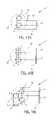
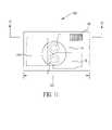
- FIG. 11is a frontal view of a digital camera employing two image capture assemblies, one fixed focal length and the other zoom, of the type shown in FIGS. 10A-10F .
- FIG. 12is a top view of the digital camera shown in FIG. 11 .
- FIG. 13is a side view of the digital camera shown in FIG. 11 .
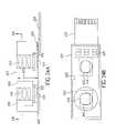
- FIGS. 14A , 14 B and 14 Care three views of a digital camera employing two image capture assemblies, both zoom, of the type shown in FIGS. 10A-10F .
- FIGS. 15A , 15 B and 15 Care three views of a digital camera employing three image capture assemblies of the type shown in FIGS. 10A-10F .
- FIGS. 16A and 16Bshow two views of the optical relay subassembly shown in the various embodiments of FIGS. 10A-10F for supporting a fixed focal length lens in relation to an image sensor along a folded optical path according to the invention.
- FIG. 17shows the optical relay subassembly shown in the various embodiments of FIGS. 10A-10F for supporting a zoom lens in relation to an image sensor along a folded optical path according to the invention.
- FIGS. 18A and 18Bshow two imagers with different panoramic aspect ratios and the effect obtained by changing the aspect ratio.
- FIG. 19depicts a block diagram of a further embodiment of a digital camera using a first fixed focal length lens with a first sensor, a second fixed focal length lens with a second sensor, and a third fixed focal length lens with a third sensor.
- FIG. 20depicts a flow diagram showing a method for capturing digital images using the digital camera shown in FIG. 19 .
- FIG. 21depicts a block diagram of a further embodiment of a digital camera using a first lens with a first sensor having pixels of one size. e.g., three micron pixels, and a second lens with a second sensor having pixels of another size, e.g., five micron pixels.
- FIG. 22is a diagram useful for explaining an express zooming feature.
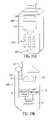
- FIGS. 23A and 23Bare perspective views of the front and back of a cell phone including a camera with multiple lenses and multiple sensors.
- FIGS. 24A and 24Bare two views of the image capture assembly used in the cell phone shown in FIGS. 23A and 23B .
- Each of the several embodiments of the present inventioninclude an image capture assembly having multiple lenses and multiple image sensors mounted within a digital camera in order to provide an extended zoom range. This can reduce the cost and size of the camera, and improve its optical performance, compared with a camera having a single sensor and a large range zoom lens (e.g. having a 10:1 zoom range). While not in an exactly coaxial arrangement with respect to each other, the multiple lenses and sensors are generally aligned with respect to each other so as to be viewing substantially the same object, albeit with different fields of view.
- Each image capture assemblycomprises two or more optical relay subassemblies having a lens and an image sensor disposed at opposing ends thereof and a folded optical path for directing the light from the lens to the sensor.
- This configurationcan further reduce the size of the optical components, thereby enabling the design and manufacture of a very thin and compact camera.
- folded opticsare used in many of the preferred embodiments, a folded optical path is not generally necessary for practice of the invention. This is particularly true for the wide angle optical subassemblies since the focal length of such wide angle lenses is very short to begin with.
- the size of the sensor, and consequently the size of the image that must be produced to fill the sensormay be small enough to reduce the focal length to an acceptable front-to-back dimension—even for normal and short telephoto focal lengths.
- the cameraincludes a control element for selecting either the first sensor output from the first image sensor or a sensor output from one of the other image sensors, thereby providing a selected sensor output that may be provided to a processing section in the camera for producing an output image.
- each embodimentincludes some type of user control that allows a user to select a focal length, either directly or via some marking (e.g., “panoramic” or “portrait”) indicative of a focal length; the aforementioned control element is then responsive to the user control for selecting a corresponding sensor output.
- a single “zoom lens” user controlis used, e.g., where the “wide” setting selects a wide angle fixed focal length lens and the “tele” setting(s) select various positions of a zoom lens.
- the user control outputis then provided to the control element, which selects the image sensor that is used to produce the output image.
- the user controlor the control element also enables the zoom and focus motors for the zoom lens to drive the zoom lens to the selected focal length.
- digital zoomingmay be used to zoom “up” from the wide angle setting to the minimum focal length setting of the zoom lens. All this, of course, may be transparent to the user, who simply manipulates the “zoom lens” user control between the “wide” and “tele” settings.
- FIGS. 10A-10Fseveral diagrams are shown of the optical layout of several embodiments of an image capture assembly 1 , which is included within the various embodiments of a digital camera (which will be described later). These diagrams include the optical relay subassemblies 1 a , 1 b and 1 c containing the aforementioned folded optical elements.
- a circle 1 ddelineates an optical profile of a front surface of a digital camera through which the respective lenses protrude.
- the optical relay subassemblies 1 a , 1 b and 1 care folded behind the lenses and, as will be described, covered by the front surface of the camera.
- a digital cameraemploys a first fixed focal length wide angle lens 2 with a first image sensor 12 , and a zoom lens 3 with a second image sensor 14 .
- an image capture assembly 1includes the first lens 2 and the first image sensor 12 mounted at opposing ends of a first optical relay subassembly 1 a having a folded optical path arranged between the first image sensor 12 and the lens 2 .
- the first lens 2which preferably is a fixed focal length wide angle lens, forms a first image of a scene on the first image sensor 12 .
- the image capture assembly 1also includes the zoom lens 3 and the second image sensor 14 mounted at opposing ends of a second optical relay subassembly 1 b having a folded optical path arranged between the second image sensor 14 and the zoom lens 3 .
- the zoom lens 3which has a range of focal lengths adjustable between a minimum focal length and a maximum focal length, forms a second image of the scene on the second image sensor 14 .
- the first lens 2is a wide angle lens having a focal length less, and preferably substantially less, than the minimum focal length of the zoom lens 3 .
- a digital cameraemploys a first zoom lens 3 with an image sensor 14 , and a second zoom lens 4 with an image sensor 16 .
- the image sensor 14will be characterized as the first image sensor 14 and the image sensor 16 will be characterized as the second image sensor 16 .
- the image capture assembly 1includes the first zoom lens 3 and the first image sensor 14 mounted at opposing ends of a first optical relay subassembly 1 b having a folded optical path arranged between the first image sensor 14 and the first zoom lens 3 .
- the first zoom lens 3which has a range of focal lengths adjustable between a minimum focal length and a maximum focal length, forms a first image of the scene on the first image sensor 14 .
- the image capture assembly 1also includes the second zoom lens 4 and the second image sensor 16 mounted at opposing ends of a second optical relay subassembly 1 c having a folded optical path arranged between the second image sensor 16 and the zoom lens 4 .
- the zoom lens 4which has a range of focal lengths adjustable between a minimum focal length and a maximum focal length, forms a second image of the scene on the second image sensor 16 .
- the maximum focal length of the first zoom lens 3is less than or equal to the minimum focal length of the second zoom lens 4 .
- the digital cameraemploys a first zoom lens 3 with an image sensor 14 , a second zoom lens 4 with an image sensor 16 and a fixed focal length, wide angle lens 2 with an image sensor 12 .
- the image sensor 14will be characterized as the first image sensor 14
- the image sensor 16will be characterized as the second image sensor 16
- the image sensor 12will be characterized as the third image sensor.
- the first zoom lens 3forms a first image of the scene on the first image sensor 14
- the second zoom lens 4forms a second image of the scene on the second image sensor 16 , similarly to what is shown and described in FIG. 10B .
- a third lens, the fixed focal length lens 2 , and the third image sensor 12are mounted at opposing ends of a third optical relay subassembly 1 a having a folded optical path arranged between the third image sensor 12 and the third lens 2 .
- the third lens 2preferably is a fixed focal length wide angle lens having a focal length less, and preferably substantially less, than the minimum focal length of the first zoom lens 3 , and the maximum focal length of the first zoom lens 3 is less than or equal to the minimum focal length of the second zoom lens 4 .
- the digital cameraemploys a first fixed focal length lens 2 a with a first image sensor 12 a , and a second fixed focal length lens 2 b with a second image sensor 12 b .
- an image capture assembly 1includes the first fixed focal length lens 2 a and the first image sensor 12 a mounted at opposing ends of a first optical relay subassembly 1 a ( 1 ) having a folded optical path arranged between the first image sensor 12 a and the first fixed focal length lens 2 a .
- the image capture assembly 1also includes the second fixed focal length lens 2 b and the second image sensor 12 b mounted at opposing ends of a second optical relay subassembly 1 a ( 2 ) having a folded optical path arranged between the second image sensor 12 b and the second fixed focal length lens 2 b .
- the first fixed focal length lens 2 ais preferably a wide angle lens and the second fixed focal lens 2 b is a telephoto lens.
- the digital cameraemploys a first fixed focal length lens 2 a with a first image sensor 12 a , a second fixed focal length lens 2 b with a second image sensor 12 b and a third fixed focal length lens 2 c with a third image sensor 12 c .
- the first lens 2 a and the first image sensor 12 aare mounted at opposing ends of a first optical relay subassembly 1 a ( 1 ) having a folded optical path arranged between the first image sensor 12 a and the first lens 2 a .
- the first lens 2 awhich preferably is a fixed focal length ultra wide angle lens, forms a first image of the scene on the first image sensor 12 a .
- the second lens 2 b and the second image sensor 12 bare mounted at opposing ends of a second optical relay subassembly 1 a ( 2 ) having a folded optical path arranged between the second image sensor 12 b and the second lens 2 b .
- the second lens 2 bwhich preferably is a fixed focal length medium angle lens, forms a second image of the scene on the second image sensor 12 b .
- the third lens 2 c and the third image sensor 12 care mounted at opposing ends of a third optical relay subassembly 1 a ( 3 ) having a folded optical path arranged between the third image sensor 12 c and the third lens 2 c .
- the third lens 2 cwhich preferably is a fixed focal length narrow angle (telephoto) lens, forms a third image of the scene on the third image sensor 12 c.
- the digital cameraemploys a first fixed focal length lens 2 a with a first image sensor 12 a , a second fixed focal length lens 2 b with a second image sensor 12 b , a third fixed focal length lens 2 c with a third image sensor 12 c , and a fourth fixed focal lens 2 d with a fourth image sensor 12 d .
- the first lens 2 a and the first image sensor 12 aare mounted at opposing ends of a first optical relay subassembly 1 a ( 1 ) having a folded optical path arranged between the first image sensor 12 a and the first lens 2 a .
- the first lens 2 awhich preferably is a fixed focal length ultra wide angle lens, forms a first image of the scene on the first image sensor 12 a .
- the second lens 2 b and the second image sensor 12 bare mounted at opposing ends of a second optical relay subassembly 1 a ( 2 ) having a folded optical path arranged between the second image sensor 12 b and the second lens 2 b .
- the second lens 2 bwhich preferably is a fixed focal length medium angle lens, forms a second image of the scene on the second image sensor 12 b .
- the third lens 2 c and the third image sensor 12 care mounted at opposing ends of a third optical relay subassembly 1 a ( 3 ) having a folded optical path arranged between the third image sensor 12 c and the third lens 2 c .
- the third lens 2 cwhich preferably is a fixed focal length narrow angle (telephoto) lens, forms a third image of the scene on the third image sensor 12 c .
- the fourth lens 2 d and the fourth image sensor 12 dare mounted at opposing ends of a fourth optical relay subassembly 1 a ( 4 ) having a folded optical path arranged between the fourth image sensor 12 d and the fourth lens 2 d .
- the fourth lens 2 dwhich preferably is a fixed focal length very narrow angle (long telephoto) lens, forms a fourth image of the scene on the fourth image sensor 12 d.
- FIG. 11provides a spatial layout of a digital camera, showing how the various components described in FIG. 10A fits within the confined space of the digital camera 10 A.
- FIGS. 11 and 12show how the image capture assembly 1 is arranged within the width-wise dimension 201 of a digital camera 10 A for the first embodiment shown in FIG. 10A .
- FIG. 11is a frontal view of the digital camera 10 A showing how the fixed focal length lens subassembly 1 a and the zoom lens subassembly 1 b are positioned to one side of the lenses 2 and 3 beneath an electronic flash 48 .
- a battery compartment 204is located on the other side of the lenses 2 and 3 .
- FIG. 12is a top view of the digital camera 10 A taken along lines 12 - 12 in FIG.
- FIG. 13is a side view of the digital camera 10 A taken along the lines 13 - 13 in FIG. 12 , and further shows the vertical spacing of the fixed focal length lens subassembly 1 a , the zoom lens subassembly 1 b , and the flash 48 .
- the folded optics employed in the subassemblies 1 a and 1 benable the image capture assembly 1 to fit within a compact front to rear dimension 210 of the camera 10 A. It is also noteworthy that the embodiment of FIG.
- FIGS. 14A , 14 B, and 14 Cshow an arrangement of the components in the second embodiment shown in FIG. 10B within the digital camera 10 B, where FIG. 14B is a top view taken along the lines 14 B- 14 B in FIG. 14A , and FIG. 14C is a side view taken along the lines 14 C- 14 C in FIG. 14B .
- FIGS. 15A , 15 B and 15 Cshow an arrangement of the components in the third embodiment shown in FIG.
- FIG. 15Bis a top view taken along the lines 15 B- 15 B in FIG. 15A
- FIG. 15Cis a side view taken along the lines 15 C- 15 C in FIG. 15B .
- the narrow front-to-back dimension 210produces a pocket-sized camera, and in the context of this invention, a pocket-sized camera with zoom, or zoom-like, features.
- the image capture assemblymay be integrated into the manufacture of the digital camera or it may stand alone as a fungible component that is, e.g., separately manufactured and supplied to a camera manufacturer for insertion into the camera.
- the image capture assemblymay further include a control section for driving the sensors and selecting either the first sensor output from the first image sensor or a sensor output from one of the other image sensors.
- the sensors in the image capture assemblymay be positioned next to each other on a common circuit board assembly, or may be packaged in a common integrated circuit package, and the lenses in the image capture assembly may be provided in a common lens assembly that mounts onto the circuit board or the integrated circuit package.
- the separate imaging arraysare part of the same CCD or CMOS integrated circuit, and the two lenses are assembled together and aligned with the sensor package.
- the lenses employedmay be provided in different spatial arrangements within the front optical profile 1 d of the digital camera. Where three lenses are employed, the three lenses may be provided within the optical profile 1 d on the camera in a triangular arrangement, as shown in FIG. 10C or 10 E. Where four lenses are employed, the four lenses may be provided within the optical profile 1 d on the camera in a rectangular arrangement as shown in FIG. 10F .
- the processing section in the cameramay include an electronic zooming capability for electronically zooming over at least a portion of the focal length gap. Consequently, if a single “zoom lens” user control is used, a transition between some settings of the user control will cause a zoom lens to move to a particular optical zoom position, while a transition between other settings of the user control will cause the processor to digitally zoom up from an optical image output of the wide angle lens.
- the electronic cameraprovides a zoom setting over a range including a wide angle optical focal length and a group of optical focal lengths provided by at least one tele zoom lens
- at least some of the intervening focal lengths in the gap between the wide angle focal length and the zoom focal lengths of the tele zoomare provided by electronically zooming up from an image captured at the wide angle optical focal length.
- the wide angle optical focal length that is being zoomedcan be provided by the maximum focal length of another (wide angle) zoom lens.
- FIGS. 16A and 16Bshow two views of the optical relay subassembly la shown in FIGS. 10A , and 10 C- 10 F for supporting a fixed focal length lens 2 in relation to an image sensor 12 along a folded optical path according to the invention.
- FIG. 16Ashows a lens barrel 6 a for supporting the outer objective of the fixed focal length lens 2 , the image sensor 12 and associated relay lens components 7 a in an optical path that is folded by a mirror prism 8 a .
- the lens barrel 6 asupports an aperture shutter assembly 9 a in the optical path.
- FIG. 16Bis a view taken along the line 16 B- 16 B in FIG.
- FIG. 17shows the optical relay subassembly 1 b (or 1 c ) shown in FIGS. 10A , 10 B and 10 C for supporting a zoom lens 3 (or 4 ) in relation to an image sensor 14 (or 16 ) along a folded optical path according to the invention.
- FIG. 17shows a fixture 6 b for supporting the outer objective of the zoom lens 3 (or 4 ), the second image sensor 14 (or third image sensor 16 ), and movable relay (zoom) lens components 7 b in an optical path that is folded by a mirror prism 8 b .
- the fixture 6 bsupports an aperture shutter assembly 9 b in the optical path.
- FIG. 17also shows the zoom and focus motors 5 a for controlling the movement of the lens components 7 b.
- FIG. 1depicts a block diagram of a digital camera 10 A, which utilizes the first embodiment of the present invention.
- the digital camera 10 Ais a portable battery operated device, small enough to be easily handheld by a user when capturing and reviewing images.
- the digital camera 10 Aproduces still digital images that are stored on a removable memory card 54 .
- the digital cameramay produce motion digital images, either exclusively or in addition to the still images, that are also stored on the memory card 54 .
- the digital camera 10 Aincludes the aforementioned image capture assembly 1 described in FIGS. 10A and 11 , comprising a fixed focal length lens 2 that focuses an image of a scene (not shown) onto a first image sensor 12 , and a zoom lens 3 which focuses an image of the scene onto a second image sensor 14 .
- the image capture assembly 1provides a first image output 12 e from the first image sensor 12 and a second image output 14 e from the second image sensor 14 .
- the images sensors 12 and 14are identical in size, both as to aspect ratio and pixel size
- the lens 2is an ultra-wide angle lens with a “35 mm film equivalent focal length” of 22 mm (written as 22 mm equiv., where 22 mm is the focal length of a 35 mm photographic film camera that provides the same field of view as the fixed lens 2 provides to the image sensor 12 , as defined in the ANSI/13A IT10.7000-2004 standard available from the American National Standards Institute, Inc., New York, N.Y.), and the zoom lens 3 is a 3:1 zoom lens having a 38 mm-114 mm equiv. focal length range.
- the image sensoruses a 1 ⁇ 2′′ type optical format, it has a focal plane of 6.4 mm (width) ⁇ 4.8 mm (height), with a diagonal distance of 8.0 mm. If this type of image sensor is used with a lens having an actual focal length of 4.0 mm, the 35 mm equiv. focal length is 22 mm.
- the fixed focal length lens 2includes an adjustable aperture and shutter assembly 9 a (as shown FIGS. 16A and 16B ) to control the exposure of the image sensor 12 .
- the zoom lens 3is controlled by zoom and focus motors 5 a and an adjustable aperture and shutter assembly 9 b (as shown in FIGS. 17A and 17B ) to control the exposure of the image sensor.
- the image sensors 12 and 14are single-chip color Megapixel CCD sensors, using the well-known Bayer color filter pattern to capture color images.
- the image sensors 12 and 14can have, for example, a 4:3 image aspect ratio and a total of 3.1 effective megapixels (million pixels), with 2048 active columns of pixels ⁇ 1536 active rows of pixels.
- the image sensors 12 and 14can use a 1 ⁇ 2′′ type optical format, so that each pixel is approximately 3.1 microns tall by 3.1 microns wide.
- a control processor and timing generator 40controls the first image sensor 12 by supplying signals to clock drivers 13 , and controls the second image sensor 14 by supplying signals to clock drivers 15 .
- the control processor and timing generator 40also controls the zoom and focus motors 5 a , and a flash 48 for emitting light to illuminate the scene.
- the control processor and timing generator 40also receives signals from automatic focus and automatic exposure detectors 46 .
- the image sensor 14could be used to provide exposure detection and “through-the-lens” autofocus, as described in commonly-assigned U.S. Pat. No. 5,668,597, which is entitled “Electronic Camera with Rapid Automatic Focus of an Image upon a Progressive Scan Image Sensor” and which issued Sep. 26, 1997 in the names of Kenneth A. Parulski, Masaki Izumi, Seiichi Mizukoshi and Nobuyuki Mori, and which is incorporated herein by reference.
- User controls 42are used to control the operation of the digital camera 10 A.
- the analog output signal 12 e from the first image sensor 12is amplified by a first analog signal processor (ASP 1 ) 22 and provided to a first input of a control element 34 , e.g., an analog multiplexer control element.
- the analog output signal 14 e from the second image sensor 14is amplified by a second analog signal processor (ASP 2 ) 24 and provided to a second input of the control element 34 , that is, the analog multiplexer control element.
- the function of the control element 34is to select either the first sensor output 12 e from the first image sensor 12 or the second sensor output 14 e from the second image sensor 14 , thereby providing a selected sensor output from the image capture assembly 1 .
- the control processor and timing generator 40controls the analog multiplexer control element 34 in order to provide the output of either the (ASP 1 ) 22 or the (ASP 2 ) 24 to an analog-to-digital (A/D) converter circuit 36 .
- the digital data provided by the A/D converter 36is stored in a DRAM buffer memory 38 and subsequently processed by an image processor 50 .
- the processing performed by the image processor 50is controlled by firmware stored in a firmware memory 58 , which can be flash EPROM memory.
- the processor 50processes the input digital image file, which is buffered in a RAM memory 56 during the processing stage.
- two A/D converter circuitsare connected to the outputs of ASP 1 ( 22 ) and ASP 2 ( 24 ) and the analog mux 34 is not used. Instead, a digital multiplexer is used to select which one of the outputs of the two A/D converters is connected to the DRAM buffer memory 38 .
- the processed digital image fileis provided to a memory card interface 52 , which stores the digital image file on the removable memory card 54 .
- Removable memory cards 54are one type of removable digital image storage medium, and are available in several different physical formats.
- the removable memory card 54can include (without limitation) memory cards adapted to well-known formats, such as the Compact Flash, SmartMedia, MemoryStick, MMC, SD, or XD memory card formats.
- Other types of removable digital image storage mediasuch as magnetic hard drives, magnetic tape, or optical disks, can alternatively be used to store the still and motion digital images.
- the digital camera 10 Acan use internal non-volatile memory (not shown), such as internal Flash EPROM memory to store the processed digital image files.
- the memory card interface 52 and the removable memory card 54are not needed.
- the image processor 50performs various housekeeping and image processing functions, including color interpolation followed by color and tone correction, in order to produce rendered sRGB image data.
- the rendered sRGB image datais then JPEG compressed and stored as a JPEG image file on the removable memory card 54 .
- the rendered sRGB image datamay also be provided to a host PC 66 via a host interface 62 communicating over a suitable interconnection, such as a SCSI connection, a USB connection or a Firewire connection.
- the JPEG fileuses the so-called “Exif” image format defined in “Digital Still Camera Image File Format (Exif)” version 2.1, July 1998 by the Japan Electronics Industries Development Association (JEIDA), Tokyo, Japan. This format includes an Exif application segment that stores particular image metadata, including the date/time the image was captured, as well as the lens f/number and other camera settings.
- the image processor 50while typically a programmable image processor, can alternatively be a hard-wired custom integrated circuit (IC) processor, a general purpose microprocessor, or a combination of hard-wired custom IC and programmable processors.
- ICintegrated circuit
- the image processor 50also creates a low-resolution “thumbnail” size image, which can be created as described in commonly-assigned U.S. Pat. No. 5,164,831, entitled “Electronic Still Camera Providing Multi-Format Storage Of Full And Reduced Resolution Images” and issued in the name of Kuchta, et al., the disclosure of which is herein incorporated by reference.
- imagescan be quickly reviewed on a color LCD image display 70 by using the thumbnail image data.
- the graphical user interface displayed on the color LCD image display 70is controlled by the user controls 42 .
- the digital camera 10 Ais included as part of a camera phone.
- the image processor 50also interfaces to a cellular processor 90 , which uses a cellular modem 92 to transmit digital images to a cellular network (not shown) using radio frequency transmissions via an antenna 94 .
- the image capture assembly 1may be an integrated assembly including the lenses 2 and 3 , the image sensors 12 and 14 , and zoom and focus motors 5 a .
- the clock drivers 13 and 15as well as the analog signal processors 22 and 24 , the analog mux 34 , and the A/D converter 36 , may be part of the integrated assembly.
- FIGS. 2A and 2Bshow perspective views of the digital camera 10 A described in relation to FIG. 1 .
- FIG. 2Ais a frontal view of the camera 10 A, showing the fixed focal length lens 2 , the zoom lens 3 and the flash 48 .
- the fixed focal length lensis preferably an ultra wide angle lens; a suitable lens has a 22 mm equiv. focal length and an f/2 maximum aperture.
- the zoom lensis preferably an ultra-thin lens, e.g., a prism lens; a suitable zoom would be a 3:1 zoom ratio lens, such as a 38-114 mm equiv. focal length zoom lens.
- a prism lensis a lens configuration, such as shown in FIGS.
- FIG. 2Bis a rear view of the camera 10 A, showing the color (LCD) image display 70 and a number of user controls 42 , including a shutter button 42 a for enabling an image capture sequence, a panoramic button 42 b for enabling a panoramic mode, a zoom button 42 c for enabling a selection of a zoom setting, and a multi-position selector 42 d for navigating through images, menu choices and the like that are displayed on the color LCD display 70 .
- a shutter button 42 afor enabling an image capture sequence
- a panoramic button 42 bfor enabling a panoramic mode
- a zoom button 42 cfor enabling a selection of a zoom setting
- a multi-position selector 42 dfor navigating through images, menu choices and the like that are displayed on the color LCD display 70 .
- the aspect ratio of the image provided by the fixed focal length lens 2 and the image sensor 12may be different than the aspect ratio of the image provided by the zoom lens 3 and the image sensor 14 .
- the image sensor 12can have a 16:9 image aspect ratio, with 2730 active columns of pixels ⁇ 1536 active rows of pixels, for a total of 4.2 effective megapixels. Consequently, the display 70 is preferably a wide aspect ratio (e.g., 16:9) format display.
- the aspect ratio of the image sensor 12(shown in broken line) may represent a panoramic image 18 (e.g., a 16:9 aspect ratio panoramic image as shown in FIG.
- the aspect ratio of the image sensor 14may represent a typical television aspect ratio image 19 (e.g., a 4:3 aspect ratio image as shown in FIG. 18B ).
- the user control 42may input user commands to the control processor and timing generator 40 for changing the aspect ratio of the stored images which are provided by the image sensor 12 in order to obtain a variable panoramic effect that transitions from the wide angle of the lens 2 toward a narrower angle approaching the effect of the 4:3 aspect ratio of the zoom lens 3 . This is accomplished by cropping the image data which has been stored in DRAM buffer memory 38 , so that only a center subset of the image data provided from the image sensor 12 is processed by image processor 50 and stored on removable memory card 54 .
- the vertical margins 18 b of the imagemay be continuously adjusted, from the normal 16:9 aspect ratio to a wider aspect ratio image, by pressing on the wide control section of the zoom button 42 c .
- the top and bottom of the image in DRAM buffer memory 38is cropped by image processor 50 to produce increasingly wider aspect ratios, such as 17:9, 18:9 (2:1), 19:9, etc. image aspect ratios.
- the horizontal margins 18 a of the imagemay be adjusted, from the normal 16:9 aspect ratio to a narrower aspect ratio image by instead pressing on the telephoto control section of the zoom button 42 c .
- the left and right sides of the image in DRAM buffer memory 38are cropped by image processor 50 to produce increasingly narrower aspect ratios, such as 15:9, 14:9, 3:2, etc. image aspect ratios.
- image processor 50may crop the left and right sides of the image in DRAM buffer memory 38 to produce increasingly narrower aspect ratios, such as 15:9, 14:9, 3:2, etc. image aspect ratios.
- a variable panoramic effectmay be digitally effected using the image data from the first image sensor 12 .
- FIG. 3depicts a flow diagram showing a method for capturing digital images using the digital camera of FIG. 1 .
- lens setting block 100when the camera 10 A is turned on using a power switch (not shown), the zoom lens 3 is set to a default position, which is preferably a wide angle position (e.g., the 38 mm position).
- panoramic decision block 102if the user presses the panoramic button 42 b (i.e., a yes response to block 102 ), the control processor and timing generator 40 controls the analog multiplexer 34 to use (first sensor block 114 ) the output of the analog signal processor (ASP 1 ) 22 , so that the output of the first image sensor 12 is provided to the A/D converter 36 .
- ASP 1analog signal processor
- a preview image from the image sensor 12is captured and displayed in preview block 116 .
- the zoom buttonis pressed at this point (having specified that the wide angle image is being used)
- the aspect ratio of the imageis modified in the aspect ratio adjustment block 118 so as to obtain a variable panoramic effect from the wide angle of the lens 2 .
- the shutter buttonis pressed, a still image is captured in capture block 120 using the output of the first sensor 12 .
- panoramic decision block 102if the user does not press the panoramic button 42 b (i.e., a no response to block 102 ), the control processor and timing generator 40 controls the analog multiplexer 34 to use (second sensor block 104 ) the output of the analog signal processor (ASP 2 ) 24 , so that the output of the second image sensor 14 is provided to A/D converter 36 . Thereupon, a preview image from the image sensor 14 is captured and displayed in preview block 106 . If the zoom button is pressed at this point (having specified that the zoom image is being used), the position of the zoom lens is adjusted in the zoom adjustment block 108 so as to obtain a zooming effect from the minimum focal length to the maximum focal length of the zoom lens 3 . Then, if the shutter button is pressed, a still image is captured in capture block 110 using the output of the second sensor 14 .
- the control processor and timing generator 40controls the analog multiplexer 34 to use (second sensor block 104 ) the output of the analog signal processor (ASP 2 ) 24 , so
- the image sensor that is not being usedmay optionally be powered down (in the power down block 112 ) to reduce the power drain and conserve the battery supply.
- FIG. 4depicts a block diagram of a digital camera 10 A, which utilizes the second embodiment of the present invention.
- a digital camera 10 Bincludes two zoom lenses, each providing an image to a corresponding image sensor.
- the first zoom lens 3is controlled by zoom and focus motors 5 a , and provides an image to the first image sensor 14 .
- the second zoom lens 4is controlled by zoom and focus motors 5 b , and provides an image to the second image sensor 16 .
- a user zoom control on the cameraselects, depending on its setting, either the output 14 e of the first image sensor 14 or the output 16 e of the second image sensor 16 .
- the remaining aspects of the digital camera 10 Bare similar to the digital camera 10 A shown in FIG. 1 , and retain the same reference characters. Reference is therefore made to FIG. 1 for further description of these aspects of the digital camera 10 B.
- FIGS. 5A and 5Bshow perspective views of the digital camera 10 B described in relation to FIG. 4 .
- FIG. 5Ais a front view of the camera 10 B, showing the first zoom lens 3 , the second zoom lens 4 and the flash 48 .
- the first zoom lens 3is preferably an ultra-thin lens, e.g., a prism lens; a suitable zoom would be an approximately 3:1 zoom ratio lens, such as a 38-114 mm equiv. focal length zoom lens.
- the second zoom lens 4is preferably another ultra-thin lens, e.g., a prism lens; a suitable zoom would be an approximately 3:1 zoom ratio lens, such as a 133-380 mm equiv. focal length zoom lens.
- a total zoom ratio of approximately 10:1may be obtained from the usage of both of the zoom lens.
- the small gap in focal length between first zoom lens 3 and the second zoom lens 4is equivalent to a focal length zoom step.
- other lens focal lengths and lens type constructionsare within the scope of the invention.
- FIG. 5Bis a rear view of the camera 10 B, and similar in all respects, except for the lack of the panoramic button 42 b , to FIG. 2B . Since neither imager has a panoramic aspect ratio, the display 70 is preferably a 4:3 aspect ratio display.
- FIG. 6depicts a flow diagram showing a method for capturing digital images using the digital camera of FIG. 4 .
- lens setting block 100when the camera 10 B is turned on using a power switch (not shown), the first zoom lens 3 is set to a default position, which is preferably a wide angle position (e.g., the 38 mm position).
- zoom position block 122if the user presses the zoom button 42 c and obtains a position beyond X (i.e., something greater than 125 mm and therefore a yes response to block 122 ), the control processor and timing generator 40 controls the analog multiplexer 34 to use (second sensor block 134 ) the output of the analog signal processor (ASP 1 ) 24 , so that the output of the second image sensor 16 is provided to the A/D converter 36 . Thereupon, a preview image from the image sensor 16 is captured and displayed in preview block 136 . Then, if the shutter button is pressed, a still image is captured in capture block 140 using the output of the second sensor 16 . If the zoom button is pressed at this point in the zoom button block 138 , control is returned to the zoom position block 122 .
- zoom position block 122if the user presses the zoom button 42 c and obtains a position less than a position X (i.e., something less than 125 mm and therefore a no response to block 122 ), the control processor and timing generator 40 controls the analog multiplexer 34 to use (first sensor block 124 ) the output of the analog signal processor (ASP 2 ) 22 , so that the output of the first image sensor 14 is provided to the A/D converter 36 . Thereupon, a preview image from the image sensor 14 is captured and displayed in preview block 126 . Then, if the shutter button 42 a is pressed, a still image is captured in capture block 130 using the output of the first sensor 16 . If the zoom button is pressed at this point in the zoom button block 128 , control is returned to the zoom position block 122 , and the process is repeated.
- first sensor block 124the output of the analog signal processor 22 .
- FIG. 7depicts a block diagram of a digital camera 10 C, which utilizes the third embodiment of the present invention.
- a digital camera 10 Cincludes two zoom lenses 3 and 4 and a fixed focal length lens 2 , each providing an image to a corresponding image sensor.
- the first zoom lens 3is controlled by zoom and focus motors 5 a , and provides an image to the first image sensor 14 .
- the second zoom lens 4is controlled by zoom and focus motors 5 b , and provides an image to the second image sensor 16 .
- the fixed focal length lens 2provides an image to the third image sensor 12 .
- a user zoom control on the cameraselects, depending on its setting, either the output 14 e of the first image sensor 14 , the output 16 e of the second image sensor 16 , or the output 12 e of the third image sensor 12 .
- the remaining aspects of the digital camera 10 Care similar to the digital camera 10 B shown in FIG. 4 , and retain the same reference characters. Reference is therefore made to FIG. 4 for further description of these aspects of the digital camera 10 C.
- FIGS. 8A and 8Bshow perspective views of the digital camera 10 C described in relation to FIG. 7 .
- FIG. 8Ais a frontal view of the camera 10 C, showing the first zoom 3 , the second zoom lens 4 , the fixed focal length lens 2 and the flash 48 .
- the first zoom lens 3is preferably an ultra-thin lens, e.g., a prism lens; a suitable zoom would be an approximately 3:1 zoom ratio lens, such as a 38-114 mm equiv. focal length zoom lens.
- the second zoom lens 4is preferably another ultra-thin lens, e.g., a prism lens; a suitable zoom would be an approximately 3:1 zoom ratio lens, such as a 133-380 mm equiv. focal length zoom lens.
- a total zoom ratio of approximately 10:1may be obtained from the usage of both of the zoom lens.
- the small gap in focal length between first zoom lens 3 and the second zoom lens 4is equivalent to a focal length zoom step.
- the fixed focal length lensis preferably an ultra wide angle lens; a suitable lens has a 22 mm equiv. focal length and an f/2 maximum aperture.
- other lens focal lengths and lens type constructionsare within the scope of the invention.
- FIG. 8Bis a rear view of the camera 10 C, and similar in all respects to FIG. 2B .
- the aspect ratio (e.g., 16:9) of the image provided by the fixed focal length lens 2may be different than the aspect ratio of the image provided by the zoom lenses 3 or 4 .
- the user control 42e.g., the zoom button 42 c
- the user control 42may input user commands for changing the aspect ratio of the image sensor 2 in order to obtain a variable panoramic effect that transitions from the wide angle of the lens 2 toward a narrower angle approaching the effect of the 4:3 aspect ratio of the zoom lens 3 .
- FIG. 9depicts a flow diagram showing a method for capturing digital images using the digital camera of FIG. 7 .
- This figureis mostly a composite of the blocks in FIGS. 3 and 6 , and most of the blocks retain the same reference characters for the same block functions and steps.
- the first and second zoom lenses 3 and 4are set to default positions, which are preferably the wide angle position of each lens (e.g., the 38 mm position for lens 3 and the 125 mm position for lens 4 ).
- panoramic decision block 102if the user presses the panoramic button 42 b (i.e., a yes response to block 102 ), the control processor and timing generator 40 controls the analog multiplexer 34 to use (third sensor block 115 ) the output of the analog signal processor (ASP 1 ) 26 , so that the output of the third image sensor 12 is provided to the A/D converter 36 . Thereupon, a preview image from the image sensor 12 is captured and displayed in preview block 116 . If the zoom button is pressed at this point (having specified that the wide angle image is being used), the aspect ratio of the image is modified in the aspect ratio adjustment block 118 so as to obtain a variable panoramic effect from the wide angle of the lens 2 . Then, if the shutter button is pressed, a still image is captured in capture block 120 using the output of the third sensor 12 .
- the control processor and timing generator 40controls the analog multiplexer 34 to use (third sensor block 115 ) the output of the analog signal processor (ASP 1 ) 26 , so that the output of the
- zoom position block 122If the panoramic decision block 102 is not engaged (i.e., the user has not pressed the panoramic button 42 b ), control is transferred to the zoom position block 122 .
- zoom position block 122if the user presses the zoom button 42 c and obtains a position beyond X (i.e., something greater than 125 mm and therefore a yes response to block 122 ), the control processor and timing generator 40 controls the analog multiplexer 34 to use (second sensor block 134 ) the output of the analog signal processor (ASP 1 ) 24 , so that the output of the second image sensor 16 is provided to the A/D converter 36 . Thereupon, a preview image from the image sensor 16 is captured and displayed in preview block 136 . Then, if the shutter button is pressed, a still image is captured in capture block 140 using the output of the second sensor 16 . If the zoom button is pressed at this point in the zoom button block 138 , control is returned to the zoom position block 122 .
- zoom position block 122if the user presses the zoom button 42 c and obtains a position less than a position X (i.e., something less than 125 mm and therefore a no response to block 122 ), the control processor and timing generator 40 controls the analog multiplexer 34 to use (first sensor block 124 ) the output of the analog signal processor (ASP 2 ) 27 , so that the output of the first image sensor 14 is provided to the A/D converter 36 . Thereupon, a preview image from the image sensor 14 is captured and displayed in preview block 126 . Then, if the shutter button 42 a is pressed, a still image is captured in capture block 130 using the output of the first sensor 16 . If the zoom button is pressed at this point in the zoom button block 128 , control is returned to the zoom position block 122 , and the process is repeated.
- first sensor block 124the output of the analog signal processor (ASP 2 ) 27
- a preview image from the image sensor 14is captured and displayed in preview block 126 .
- FIG. 19represents the fourth and fifth embodiments of the invention, where a digital camera 10 D includes two (the fourth embodiment) fixed focal length lenses or a digital camera 10 E includes three (the fifth embodiment) fixed focal length lenses, each providing an image to a corresponding imaging array.
- FIG. 19specifically depicts a block diagram of a digital camera 10 E according to the fifth embodiment of the present invention.
- a digital camera 10 Eincludes three fixed focal length lens, each providing an image to a corresponding image sensor.
- the first fixed focal length lens 2 aprovides an image to the first image sensor 12 a .
- the second fixed focal length lens 2 bprovides an image to the second image sensor 12 b .
- the third fixed focal length lens 2 cprovides an image to the third image sensor 12 c .
- a user zoom control on the cameraselects, depending on its setting, either the output of the first image sensor 12 a , the output of the second image sensor 12 b , or the output of the third image sensor 12 c . More specifically, the user zoom control on the camera selects either the output of one of the three image sensors to provide a rough magnification setting, and in addition uses a digital zoom provided by the image processor 50 to provide fine magnification control.
- the first focal length lens 2 amay have a focal length of 30 mm equiv. (35 mm equivalent)
- the second fixed focal length 2 b lensmay have a focal length of 90 mm equiv.
- the third fixed focal length lens 2 cmay have a focal length of 135 mm equiv.
- the zoom lens controlmay provide settings from 30 mm to 270 mm.
- the output from the first sensor 12 ais selected, along with a 2 ⁇ digital zoom.
- the output of the third sensor 12 cis selected, along with 2 ⁇ digital zoom.
- a digital camera 10 Dincludes two fixed focal length lens, each providing an image to a corresponding image sensor. Consequently, for the fourth embodiment, FIG. 19 is modified such that the third fixed focal length lens 2 c , and its ancillary components and circuitry, is eliminated.
- a user zoom control on the cameraselects, depending on its setting, either the output of the first image sensor 12 a , or the output of the second image sensor 12 b .
- the first focal length lens 2 amay have a focal length of 30 mm equiv. (35 mm equivalent)
- the second fixed focal length 2 b lensmay have a focal length of 90 mm equiv.
- the zoom lens control 42 cmay provide settings from 30 mm to 270 mm.
- the output from the first sensor 12 ais selected, along with a 2 ⁇ digital zoom.
- the output of the second sensor 12 bis selected, along with 3 ⁇ digital zoom.
- the remaining aspects of the digital cameras 10 D and 10 Eare similar to the digital camera 10 B shown in FIG. 4 , and retain the same reference characters. Reference is therefore made to FIG. 4 for further description of these aspects of the digital cameras 10 D and 10 E.
- the perspective views of digital cameras 10 D and 10 Eare not shown, as they are substantially similar to the perspective views of FIGS. 5A and 5B , except that another optical relay subassembly is included for the digital camera 10 E.
- FIG. 20depicts a flow diagram showing a method for capturing digital images using the digital camera 10 E of FIG. 20 .
- a power up block 300the camera 10 E is turned on using a power switch (not shown).
- zoom position block 302if the user presses the zoom button 42 c and obtains a position beyond X (e.g., something equal to or greater than 90 mm equiv. and therefore a yes response to block 302 ), control is transferred to the second zoom position block 314 . There, if the zoom button 42 c is indicating a position beyond Y (e.g., something equal to or greater than 135 mm equiv.
- the control processor and timing generator 40controls the analog multiplexer 34 to use (third sensor block 318 ) the output of the analog signal processor (ASP 3 ) 26 , so that the output of the third image sensor 12 c is provided to the A/D converter 36 .
- the zoom control 42 cis requesting a focal length other than the optical 135 mm equiv., digital zoom is applied to the image in the zoom block 306 to bring the image up to the requested focal length.
- a preview image from the image sensor 12 cis captured and displayed in preview block 308 .
- the shutter buttonis pressed, a still image is captured in capture block 312 using the output of the third sensor 12 c . If the zoom button is pressed at this point in the zoom button block 310 , control is instead returned to the zoom position block 302 .
- the control processor and timing generator 40controls the analog multiplexer 34 to use (second sensor block 316 ) the output of the analog signal processor (ASP 2 ) 24 , so that the output of the second image sensor 12 b is provided to the A/D converter 36 .
- the zoom control 42 cis requesting a focal length other than the optical 90 mm equiv., digital zoom is applied to the image in the zoom block 306 to bring the image up to the requested focal length. Thereupon, a preview image from the image sensor 12 b is captured and displayed in preview block 308 .
- zoom position block 302if the user presses the zoom button 42 c and obtains a position less than a position X (i.e., something less than 90 and therefore a no response to block 302 ), the control processor and timing generator 40 controls the analog multiplexer 34 to use (first sensor block 304 ) the output of the analog signal processor (ASP 1 ) 22 , so that the output of the first image sensor 12 a is provided to the A/D converter 36 . If the zoom control 42 c is requesting a focal length other than the optical 30 mm equiv., digital zoom is applied to the image in the zoom block 306 to bring the image up to the requested focal length.
- a preview image from the image sensor 12 ais captured and displayed in preview block 308 .
- the shutter button 42 ais pressed, a still image is captured in capture block 312 using the output of the first sensor 12 a . If the zoom button is pressed at this point in the zoom button block 310 , control is returned to the zoom position block 302 , and the process is repeated.
- a number of advantagesmay be obtained by use of the fixed focal length lenses in the fourth and fifth embodiments.
- the aperture of each lenscan be kept quite large (e.g., f/2.8 at least for the widest angle lens), thereby providing a high speed, low light lens.
- the image qualitycan be kept higher than for a comparable zoom lens.
- a digital camera 10 Fincludes four fixed focal length lenses, each providing an image to a corresponding image sensor. Consequently, for the sixth embodiment, FIG. 19 is modified such that a fourth fixed focal length lens 2 d , and its ancillary components and circuitry, is added.
- a user zoom control on the cameraselects, depending on its setting, either the output of the first image sensor 12 a , the output of the second image sensor 12 b , the output of the third sensor 12 c , or the output of the fourth sensor 12 d .
- the first focal length lens 2 amay have a focal length of 30 mm equiv.
- the zoom lens control 42 cmay provide settings from 30 mm to 400 mm.
- the zoom lens control 42 cmay provide settings from 30 mm to 400 mm.
- the output from the third sensor 12 cis selected, along with a 2 ⁇ digital zoom.
- the output of the fourth sensor 12 dis selected, along with 1.5 ⁇ digital zoom.
- the remaining aspects of the digital camera 10 Fare similar to the digital camera 10 E shown in FIG. 19 , and reference is therefore made to FIG. 19 for further description of these aspects of the digital camera.
- the perspective views and flow diagram of the digital camera 10 Fare not shown, as they are substantially similar to the perspective views of FIGS. 5A and 5B and the flow diagram of FIG. 20 , except that yet another optical relay subassembly, and another flow column in FIG. 20 for the fourth sensor 12 c , is included for the digital camera 10 F.
- digital zoomingis used.
- Digital zoomingis a well-known process and any of a variety of techniques may be used.
- One such digital zooming capabilityis described in commonly-assigned pending U.S. Patent Application Publication No. 2003/0202113, “Electronic Still Camera and Image Processing Method” filed on Aug. 1, 2002 in the name of Sumito Yoshikawa and which is incorporated herein by reference.
- the image sensorincludes an array of discrete light sensitive picture elements overlaid with a color filter array (CFA) pattern to produce color image data corresponding to the CFA pattern.
- the output data from the image sensoris applied to an analog signal processing (ASP) and analog/digital (A/D) conversion section, which produces digital CFA data from the color image data.
- ASPanalog signal processing
- A/Danalog/digital
- the resultant digital datais applied to a digital signal processor, such as the image processor 50 (referring to FIG. 1 of the present disclosure), which interpolates red, green, and blue (RGB) color image data for all of the pixels of the color image sensor.
- the CFA image datarepresents an image of a fixed size, such as 2048 columns of pixels ⁇ 1536 rows of pixels.
- a digitally zoomed imageis provided by taking the center section of the CFA image data and interpolating additional pixels that fall in between the pixels provided by the image sensor. For example, a 2:1 digital zoom is provided by using only the center 1024 columns ⁇ 768 rows of the CFA image data, and by interpolating one additional row and column in between each of the rows and columns of the center CFA image data, so as to enlarge the center of the image.
- the output of the image processor 50is a color interpolated and digitally zoomed image, with 2048 columns and 1536 rows of RGB data, provided from the center 1024 columns ⁇ 768 rows of CFA image data.
- the useroperates the digital camera, e.g., the digital camera 10 E ( FIG. 19 ), to take pictures while observing the image on the color LCD image display 70 .
- the digital CFA image for each of the captured imagesis processed by the image processor 50 and displayed in a “thumbnail” or subsampled format in the preview step (e.g., steps 308 in FIG. 20 ). If the observed zoom amount is not desired, the user then changes the zooming/cropping setting in a zoom selection/cropping step (e.g., steps 302 , 314 in FIG. 20 ) by using the zoom button 42 c .
- the amount of digital zoomingis determined by the control processor and timing generator 40 and provided to the image processor 50 .
- the control processor and timing generator 40selects which of the image sensor outputs to use (by controlling the analog mux 34 ), and the amount of digital zoom needed, which in combination provide the desired overall zoom setting.
- a 2.5:1 overall zoom settingcan be provided by selecting (using the analog mux 34 ) a lens and image sensor that provides a 2:1 optical zoom and also instructing the image processor 50 to provide a 5:4 digital zoom setting, which uses the center 1638 columns ⁇ 1230 rows (from the 2048 columns ⁇ 1536 rows of CFA image data).
- the two (or three) lenseshave identical focal lengths, and the imaging arrays are different sizes (e.g. both sensors are, e.g., 3.1 effective megapixel sensors with 2048 columns ⁇ 1536 rows of pixels, but the first image sensor 412 a has 3.1 micron square pixels and the second image sensor 412 b has 6.2 micron square pixels, so that the diagonal of the second image sensor is twice as large as the first image sensor).
- each lensis designed to fill the area of the imaging array and each lens-array combination can have substantially the same actual focal length, i.e., the same lens to array distance.
- a digital camera 10 Gincludes a first fixed focal length lens 402 a that provides an image to a first image sensor 412 a , which has 3.1 micron pixels.
- a second fixed focal length lens 402 bprovides an image to a second image sensor 412 b , which has 6.2 micron pixels.
- a user zoom control 42 on the cameraselects, depending on its setting, either the output of the first image sensor 412 a or the output of the second image sensor 412 b .
- the user zoom control on the cameraselects the output of one of the two image sensors to provide a rough magnification setting based on the 35 mm equiv. focal length of the lenses 402 a and 402 b , and in addition uses a digital zoom provided by the image processor 50 to provide fine magnification control.
- the first focal length lens 402 amay have an actual focal length of 16 mm, which provides a 35 mm equiv. focal length of about 80 mm because the pixels are 3.1 mm so that the diagonal size is about 8 mm.
- the second fixed focal length 402 b lensmay also have an actual focal length of 16 mm, but it provides a 35 mm equivalent focal length of about 40 mm, because the pixels are 6.2 mm so that the diagonal size is about 16 mm.
- the zoom lens controlmay provide settings from 40 mm to 160 mm. When the user selects 60 mm, for example, the output from the second sensor 412 b is selected, along with a 1.5 ⁇ digital zoom. When the user selects 160 mm, for example, the output of the first sensor 412 a is selected, along with 2 ⁇ digital zoom.
- the remaining aspects of the digital cameras 10 Gare similar to the digital camera 10 B shown in FIG. 4 , and retain the same reference characters. Reference is therefore made to FIG. 4 for further description of these aspects of the digital camera 10 G.
- a further advantage of the inventionis that use of dual zooms provides an extended optical zoom range in a digital camera where the movement between user-requested zoom positions may be undertaken in an expedited manner. Since motorized zooming is typically done between discrete zoom steps rather than continuously, the full range of a zoom system is divided into a finite number of discrete steps. For example, as shown in FIG. 22 , a two zoom system in accordance with the invention may be divided into a first zoom range 500 providing a 38 mm-114 mm equiv. zoom lens range and a second zoom range 502 providing a 133 mm-380 mm equiv. zoom lens range Such an arrangement may be provided by the digital camera 10 B shown in FIG. 4 .
- the zoom and focus motors 5 a and 5 bdrive the respective zoom lenses 3 and 4 through a finite series of discrete steps, where each step represents, for the example shown in FIG. 22 , 0.5 ⁇ zoom steps over the lower zoom range, and 1 ⁇ zoom steps over the higher zoom range More particularly, the zoom and focus motor 5 a drives the zoom lens 3 from 38 mm to 114 mm in five discrete steps, with the steps corresponding to 1 ⁇ (38 mm), 1.5 ⁇ (57 mm), 2 ⁇ (76 mm), 2.5 ⁇ (95 mm) and 3 ⁇ (114 mm) zoom steps.
- the zoom and focus motor 5 bdrives the zoom lens 4 from 133 mm to 380 mm in seven discrete steps, with the steps corresponding to 3.5 ⁇ (133 mm), 4 ⁇ (152 mm), 5 ⁇ (190 mm), 6 ⁇ (228 mm), 7 ⁇ (266 mm), 8 ⁇ (304 mm), 9 ⁇ (342 mm), and 10 ⁇ (380 mm) zoom steps.
- the two lensesare separated in focal length by a one step gap 503 (i.e., by 19 mm, corresponding to the 0.5 ⁇ gap between the 3 ⁇ zoom focal length and the 3.5 ⁇ zoom focal length.).
- the useroperates the user control 42 in order to select a zoom setting, whereby the zoom and focus motors 5 a and 5 b are responsive to the user control 42 for adjusting the zoom lenses through the first plurality of discrete zoom positions 500 for the first zoom lens 3 and through the second plurality 502 of discrete zoom positions for the second zoom lens 4 .
- the control processor and timing generator 40acting as a zoom controller, controls the zoom and focus motors 5 a and 5 b and enables an express mode when a user initiated change in the user control specifies a zoom transition from a present zoom setting within one of the plurality of discrete zoom positions in one of the ranges to a target zoom setting within the other plurality of discrete zoom positions in the other range.
- the control processor and timing generator 40causes the zoom and focus motor of the lens containing the target position to immediately move the corresponding zoom lens to the target zoom position without powering the other zoom and position motor through any intervening discrete zoom positions, thereby enabling an express zooming sequence in which the zoom and focus motors of the lens not containing the target position do not have to traverse all of the intervening zoom positions between the present zoom setting and the target zoom setting.
- both zoom lenseswill be brought to their minimum focal length positions, i.e., the zoom lens 3 will be driven to the 38 mm position and the zoom lens 4 will be driven to the 133 mm position. If the user initially chooses to view a subject at the widest angle position, say 38 mm equiv., the zoom lens 3 will provide its widest angle image to the image sensor 14 ( FIG. 4 ) and the analog multiplexer 34 will select the first image output 14 e from the first image sensor 14 .
- the control processor and timing generator 40immediately directs the zoom and focus motor 5 b to drive the lens 4 through a 3 step sequence 506 from 133 mm to 228 mm. Meanwhile, the zoom lens 3 remains at its widest setting. Consequently, five steps of movement are saved and the movement between user-requested zoom positions is undertaken in an expedited manner compared to the prior art situations.
- FIG. 22the zoom button 42 c to a tele position, say 228 mm equiv.
- step length and zoom rangesare within the scope of the invention.
- the lens 4in power up mode, the lens 4 could be set to the maximum focal length (380 mm) rather than the widest focal length (133 mm). Then the camera could be immediately switched from the wide-angle position (38 mm equiv.) to the maximum telephoto position (380 mm equiv.) immediately, simply by switching the analog mux 34 to provide the output of the 2 nd image sensor 16 .
- a cell phone 600includes a phone stage comprising a microphone 602 for capturing the voice of a caller, related electronics (not shown) for processing the voice signals of the caller and the person called, and a speaker 604 for reproducing the voice of the one called.
- a keypad 606is provided for entering phone numbers and image capture commands, and a (LCD) display 608 for showing phone-related data and for reproducing images captured by the phone or received over the cellular network.
- a cellular image capture assembly 610connected via the image processor 50 (as shown in FIG. 1 ) to a cellular processing stage comprising the cellular processor 90 and the modem 92 .
- the cellular processor 90receives and processes the image data from the image processor 50 and the voice data captured by the microphone 602 , and transfers the image and voice data to the cellular modem 92 .
- the cellular modem 92converts the digital image and voice data into the appropriate format for transmission by the antenna 94 to a cellular network.
- the assembly 610comprises an integrated packaging of the optical and imaging components on a common substrate 620 . More specifically, the assembly 610 includes a first fixed focal length lens 612 and a first image sensor 614 , and a second fixed focal length lens 616 and a second image sensor 618 .
- the first lens 612preferably a fixed focal length wide angle lens (such as a 40 mm equiv.
- the lensforms an image on the first image sensor 614
- the second lens 616preferably a fixed focal length telephoto lens (such as 100 mm equiv. lens), forms an image on the second image sensor 618 .
- Both of the lensesare oriented in the same direction in order to form images of the same portion of the overall scene in front of them, albeit with different fields of view.
- Each lens 612 and 616 and each associated image sensor 614 and 618are mounted to the substrate 620 with an IR cut filter in between to reduce the incidence of IR radiation on the image pixels.
- Electronic components 624such as resistors, capacitors and power management components, are also mounted on the substrate 620 .
- the image signalsare taken from the substrate 620 via a flex connector 626 .
- the data taken from the assembly 610may be raw image data, or if suitable processors (not shown) are on board the substrate 620 , the data could be YUV image data or JPEG image data.
- the image processor 50may provide digital zooming between the wide angle and the telephoto focal lengths; the user may initiate such zooming via a user interface displayed on the (LCD) display 608 and by keying appropriate buttons on the keypad 606 .
- the wide angle image sensor 614may have high resolution, e.g., higher than that of the telephoto image sensor 618 , in order to provide a higher quality source image for the digital zooming.
- the wide angle lens 612is set to its hyperfocal distance, which means it is in focus from a few feet to infinity without need for any focus adjustment by the user.
- the telephoto lens 616is automatically focused by an auto focus subsystem 628 . This is required because the hyperfocal distance increases as the focal length increases, and so the focus needs to be adjusted in order to obtain proper focus for objects at typical (e.g. 4′ to 12′) distances. By using only one focusing subsystem 628 for the telephoto lens 616 , the cost and size can be reduced.
- z dimension 630An important constraint in this embodiment is the “z” dimension 630 , which must be held to a very small figure consistent with a cell phone layout and architecture. This may be obtained by careful choice of the telephoto focal length and the size of the sensor. For example, the size of the sensor 616 , and consequently the size of the image that must be produced to fill the sensor, may be made small enough to reduce the focal length to an acceptable z dimension 630 .
- the two lensesmay have approximately identical focal lengths, with the imaging arrays being of different sizes.
- each lensis designed to fill the area of the imaging array and each lens-array combination will have substantially the same actual focal length, i.e., the same lens to array distance.
- the 35 mm equiv. of each lenswill be different; consequently, each lens will have a different field of view.
- an analog output signal from the first image sensor 614is amplified by a first analog signal processor and provided to a first input of a control element, e.g., an analog multiplexer control element provided as one of the electronic components 624 on the substrate 620 .
- the analog output signal from the second image sensor 618is amplified by a second analog signal processor and provided to a second input of the control element.
- control elementThe function of the control element is to select either the first sensor output from the first image sensor 614 or the second sensor output from the second image sensor 618 , depending on user input from the keypad 606 as to zoom selection, thereby providing a selected sensor output from the cellular image capture assembly 600 to the image processor 50 .
Landscapes
- Engineering & Computer Science (AREA)
- Multimedia (AREA)
- Signal Processing (AREA)
- Cameras In General (AREA)
- Studio Devices (AREA)
Abstract
Description
35 mm-equiv.f.l=(actual lensf.l. (in mm)×43.27 mm)/(diagonal sensor focal plane distance (in mm)).
For example, if the image sensor uses a ½″ type optical format, it has a focal plane of 6.4 mm (width)×4.8 mm (height), with a diagonal distance of 8.0 mm. If this type of image sensor is used with a lens having an actual focal length of 4.0 mm, the 35 mm equiv. focal length is 22 mm.
- 1 image capture assembly
- 1aoptical relay subassembly
- 1boptical relay subassembly
- 1coptical relay subassembly
- 1a(1) first optical relay subassembly
- 1a(2) second optical relay subassembly
- 1a(3) third optical relay subassembly
- 1a(4) fourth optical relay subassembly
- 1dfront optical profile of the camera
- 2 fixed focal length lens
- 2afirst fixed focal length lens
- 2bsecond fixed focal length lens
- 2cthird fixed focal length lens
- 2dfourth fixed focal length lens
- 2efirst image sensor output
- 3 first zoom lens
- 4 (second) zoom lens
- 5azoom and focus motors
- 5bzoom and focus motors
- 5cconnecting gear train
- 6alens barrel
- 6bfixture
- 7arelay lens components
- 7bmovable relay (zoom) lens components
- 8amirror prism
- 8bmirror prism
- 9aaperture shutter assembly
- 9baperture shutter assembly
- 10A digital camera (first embodiment)
- 10B digital camera (second embodiment)
- 10C digital camera (third embodiment)
- 10D digital camera (fourth embodiment)
- 10E digital camera (fifth embodiment)
- 10F digital camera (sixth embodiment)
- 10G digital camera (seventh embodiment)
- 12 first image sensor
- 12afirst image sensor
- 12bsecond image sensor
- 12cthird image sensor
- 12dfourth image sensor
- 12efirst image output
- 13 clock drivers
- 14 second image sensor
- 14esecond image output
- 15 clock drivers
- 16 third image sensor
- 16ethird image output
- 17 clock drivers
- 18 16:9 aspect ratio panoramic image
- 18ahorizontal margin
- 18bvertical margin
- 19 4:3 aspect ratio image
- 22 first analog signal processor (ASP1)
- 24 second analog signal processor (ASP2)
- 26 third analog signal processor (ASP3)
- 34 control element (analog multiplexer)
- 36 analog-to-digital converter
- 38 DRAM buffer memory
- 40 control processor and timing generator
- 42 user controls
- 42ashutter button
- 42bpanoramic button
- 42czoom button
- 42dmulti-position selector
- 46 automatic focus and automatic exposure detectors
- 48 electronic flash
- 50 image processor
- 52 memory card interface
- 54 removable memory card
- 56 RAM memory
- 58 firmware memory
- 62 host interface
- 64 interconnection
- 66 host PC
- 70 color LCD image display
- 90 cellular processor
- 92 cellular modem
- 94 antenna
- 100 lens setting block
- 102 panoramic decision block
- 104 second sensor block
- 106 preview block
- 108 zoom adjustment block
- 110 capture block
- 112 power down block
- 114 first sensor block
- 115 third sensor block
- 116 preview block
- 118 aspect ratio adjustment block
- 120 capture block
- 122 zoom position block
- 124 first sensor block
- 126 preview block
- 128 zoom button block
- 130 capture block
- 134 second sensor block
- 136 preview block
- 138 zoom button block
- 140 capture block
- 201 width-wise dimension
- 204 battery
- 210 front to rear dimension
- 300 power up block
- 302 zoom position X block
- 304 first sensor block
- 306 digital zoom block
- 308 preview block
- 310 zoom button block
- 312 capture block
- 314 zoom position Y block
- 316 second sensor block
- 318 third sensor block
- 320 removed section
- 322 yes response
- 402afirst lens
- 402bsecond lens
- 412afirst (smaller) sensor
- 412bsecond (larger) sensor
- 500 first zoom range
- 502 second zoom range
- 503 one step gap
- 504 17 step zoom sequence
- 506 9 step zoom sequence
- 600 cell phone
- 602 microphone
- 604 speaker
- 606 keypad
- 608 (LCD) display
- 610 cellular image capture assembly
- 612 first fixed focal length lens
- 614 first image sensor
- 616 second fixed focal length lens
- 618 second image sensor
- 620 substrate
- 622 IR cut filter
- 624 electronic components
- 626 flex connector
- 628 auto focus subsystem
- 630 z dimension
Claims (10)
Priority Applications (1)
| Application Number | Priority Date | Filing Date | Title |
|---|---|---|---|
| US11/061,001US7256944B2 (en) | 2005-02-18 | 2005-02-18 | Compact image capture assembly using multiple lenses and image sensors to provide an extended zoom range |
Applications Claiming Priority (1)
| Application Number | Priority Date | Filing Date | Title |
|---|---|---|---|
| US11/061,001US7256944B2 (en) | 2005-02-18 | 2005-02-18 | Compact image capture assembly using multiple lenses and image sensors to provide an extended zoom range |
Publications (2)
| Publication Number | Publication Date |
|---|---|
| US20060187311A1 US20060187311A1 (en) | 2006-08-24 |
| US7256944B2true US7256944B2 (en) | 2007-08-14 |
Family
ID=36912260
Family Applications (1)
| Application Number | Title | Priority Date | Filing Date |
|---|---|---|---|
| US11/061,001Expired - LifetimeUS7256944B2 (en) | 2005-02-18 | 2005-02-18 | Compact image capture assembly using multiple lenses and image sensors to provide an extended zoom range |
Country Status (1)
| Country | Link |
|---|---|
| US (1) | US7256944B2 (en) |
Cited By (71)
| Publication number | Priority date | Publication date | Assignee | Title |
|---|---|---|---|---|
| US20060146144A1 (en)* | 2005-01-05 | 2006-07-06 | Nokia Corporation | Digital imaging with autofocus |
| US20070002159A1 (en)* | 2005-07-01 | 2007-01-04 | Olsen Richard I | Method and apparatus for use in camera and systems employing same |
| US20070211164A1 (en)* | 2004-08-25 | 2007-09-13 | Olsen Richard I | Imager module optical focus and assembly method |
| US20070247725A1 (en)* | 2006-03-06 | 2007-10-25 | Cdm Optics, Inc. | Zoom lens systems with wavefront coding |
| US20070257184A1 (en)* | 2005-08-25 | 2007-11-08 | Olsen Richard I | Large dynamic range cameras |
| US20070295893A1 (en)* | 2004-08-25 | 2007-12-27 | Olsen Richard I | Lens frame and optical focus assembly for imager module |
| US20070296835A1 (en)* | 2005-08-25 | 2007-12-27 | Olsen Richard I | Digital cameras with direct luminance and chrominance detection |
| US20080030597A1 (en)* | 2004-08-25 | 2008-02-07 | Newport Imaging Corporation | Digital camera with multiple pipeline signal processors |
| US20080029714A1 (en)* | 2005-08-25 | 2008-02-07 | Newport Imaging Corporation | Digital camera with integrated infrared (IR) response |
| US20080158393A1 (en)* | 2006-12-28 | 2008-07-03 | Samsung Techwin Co., Ltd. | Apparatus and method for photographing |
| US20080174670A1 (en)* | 2004-08-25 | 2008-07-24 | Richard Ian Olsen | Simultaneous multiple field of view digital cameras |
| US20100097442A1 (en)* | 2008-10-16 | 2010-04-22 | Peter Lablans | Controller in a Camera for Creating a Panoramic Image |
| US20110059341A1 (en)* | 2008-06-12 | 2011-03-10 | Junichi Matsumoto | Electric vehicle |
| US20120056979A1 (en)* | 2000-03-06 | 2012-03-08 | Edwards Eric D | System and method for capturing adjacent images by utilizing a panorama mode |
| US8803944B2 (en) | 2008-10-16 | 2014-08-12 | Spatial Cam Llc | Controller in a camera for creating a registered video image |
| US20150326793A1 (en)* | 2014-05-06 | 2015-11-12 | Nokia Technologies Oy | Zoom input and camera information |
| RU2594169C1 (en)* | 2015-10-01 | 2016-08-10 | Вячеслав Михайлович Смелков | Device of computer system for panoramic television surveillance |
| WO2016192627A1 (en)* | 2015-06-05 | 2016-12-08 | 深圳市星苑科技有限公司 | Imaging device and method of zoom lens |
| US10156706B2 (en) | 2014-08-10 | 2018-12-18 | Corephotonics Ltd. | Zoom dual-aperture camera with folded lens |
| US10225479B2 (en) | 2013-06-13 | 2019-03-05 | Corephotonics Ltd. | Dual aperture zoom digital camera |
| US10230898B2 (en) | 2015-08-13 | 2019-03-12 | Corephotonics Ltd. | Dual aperture zoom camera with video support and switching / non-switching dynamic control |
| US10250797B2 (en) | 2013-08-01 | 2019-04-02 | Corephotonics Ltd. | Thin multi-aperture imaging system with auto-focus and methods for using same |
| US10284780B2 (en) | 2015-09-06 | 2019-05-07 | Corephotonics Ltd. | Auto focus and optical image stabilization with roll compensation in a compact folded camera |
| US10288840B2 (en) | 2015-01-03 | 2019-05-14 | Corephotonics Ltd | Miniature telephoto lens module and a camera utilizing such a lens module |
| US10288897B2 (en) | 2015-04-02 | 2019-05-14 | Corephotonics Ltd. | Dual voice coil motor structure in a dual-optical module camera |
| US10288896B2 (en) | 2013-07-04 | 2019-05-14 | Corephotonics Ltd. | Thin dual-aperture zoom digital camera |
| US10356304B2 (en) | 2010-09-13 | 2019-07-16 | Contour Ip Holding, Llc | Portable digital video camera configured for remote image acquisition control and viewing |
| US10371928B2 (en) | 2015-04-16 | 2019-08-06 | Corephotonics Ltd | Auto focus and optical image stabilization in a compact folded camera |
| US10379371B2 (en) | 2015-05-28 | 2019-08-13 | Corephotonics Ltd | Bi-directional stiffness for optical image stabilization in a dual-aperture digital camera |
| US10477078B2 (en) | 2007-07-30 | 2019-11-12 | Contour Ip Holding, Llc | Image orientation control for a portable digital video camera |
| US10488631B2 (en) | 2016-05-30 | 2019-11-26 | Corephotonics Ltd. | Rotational ball-guided voice coil motor |
| US10534153B2 (en) | 2017-02-23 | 2020-01-14 | Corephotonics Ltd. | Folded camera lens designs |
| US10539763B2 (en) | 2016-03-31 | 2020-01-21 | Sony Corporation | Optical system, electronic device, camera, method and computer program |
| US10578948B2 (en) | 2015-12-29 | 2020-03-03 | Corephotonics Ltd. | Dual-aperture zoom digital camera with automatic adjustable tele field of view |
| US10616484B2 (en) | 2016-06-19 | 2020-04-07 | Corephotonics Ltd. | Frame syncrhonization in a dual-aperture camera system |
| US10645286B2 (en) | 2017-03-15 | 2020-05-05 | Corephotonics Ltd. | Camera with panoramic scanning range |
| US10694168B2 (en) | 2018-04-22 | 2020-06-23 | Corephotonics Ltd. | System and method for mitigating or preventing eye damage from structured light IR/NIR projector systems |
| US10706518B2 (en) | 2016-07-07 | 2020-07-07 | Corephotonics Ltd. | Dual camera system with improved video smooth transition by image blending |
| US10845565B2 (en) | 2016-07-07 | 2020-11-24 | Corephotonics Ltd. | Linear ball guided voice coil motor for folded optic |
| US10884321B2 (en) | 2017-01-12 | 2021-01-05 | Corephotonics Ltd. | Compact folded camera |
| US10904512B2 (en) | 2017-09-06 | 2021-01-26 | Corephotonics Ltd. | Combined stereoscopic and phase detection depth mapping in a dual aperture camera |
| USRE48444E1 (en) | 2012-11-28 | 2021-02-16 | Corephotonics Ltd. | High resolution thin multi-aperture imaging systems |
| US10951834B2 (en) | 2017-10-03 | 2021-03-16 | Corephotonics Ltd. | Synthetically enlarged camera aperture |
| US10976567B2 (en) | 2018-02-05 | 2021-04-13 | Corephotonics Ltd. | Reduced height penalty for folded camera |
| US11268830B2 (en) | 2018-04-23 | 2022-03-08 | Corephotonics Ltd | Optical-path folding-element with an extended two degree of freedom rotation range |
| US11287081B2 (en) | 2019-01-07 | 2022-03-29 | Corephotonics Ltd. | Rotation mechanism with sliding joint |
| US11315276B2 (en) | 2019-03-09 | 2022-04-26 | Corephotonics Ltd. | System and method for dynamic stereoscopic calibration |
| US11333955B2 (en) | 2017-11-23 | 2022-05-17 | Corephotonics Ltd. | Compact folded camera structure |
| US11363180B2 (en) | 2018-08-04 | 2022-06-14 | Corephotonics Ltd. | Switchable continuous display information system above camera |
| US11368631B1 (en) | 2019-07-31 | 2022-06-21 | Corephotonics Ltd. | System and method for creating background blur in camera panning or motion |
| US11531209B2 (en) | 2016-12-28 | 2022-12-20 | Corephotonics Ltd. | Folded camera structure with an extended light-folding-element scanning range |
| US11635596B2 (en) | 2018-08-22 | 2023-04-25 | Corephotonics Ltd. | Two-state zoom folded camera |
| US11637977B2 (en) | 2020-07-15 | 2023-04-25 | Corephotonics Ltd. | Image sensors and sensing methods to obtain time-of-flight and phase detection information |
| US11640047B2 (en) | 2018-02-12 | 2023-05-02 | Corephotonics Ltd. | Folded camera with optical image stabilization |
| US11659135B2 (en) | 2019-10-30 | 2023-05-23 | Corephotonics Ltd. | Slow or fast motion video using depth information |
| US11693064B2 (en) | 2020-04-26 | 2023-07-04 | Corephotonics Ltd. | Temperature control for Hall bar sensor correction |
| US11770618B2 (en) | 2019-12-09 | 2023-09-26 | Corephotonics Ltd. | Systems and methods for obtaining a smart panoramic image |
| US11770609B2 (en) | 2020-05-30 | 2023-09-26 | Corephotonics Ltd. | Systems and methods for obtaining a super macro image |
| US11832018B2 (en) | 2020-05-17 | 2023-11-28 | Corephotonics Ltd. | Image stitching in the presence of a full field of view reference image |
| US11910089B2 (en) | 2020-07-15 | 2024-02-20 | Corephotonics Lid. | Point of view aberrations correction in a scanning folded camera |
| US11927874B2 (en) | 2014-07-01 | 2024-03-12 | Apple Inc. | Mobile camera system |
| US11946775B2 (en) | 2020-07-31 | 2024-04-02 | Corephotonics Ltd. | Hall sensor—magnet geometry for large stroke linear position sensing |
| US11949976B2 (en) | 2019-12-09 | 2024-04-02 | Corephotonics Ltd. | Systems and methods for obtaining a smart panoramic image |
| US11968453B2 (en) | 2020-08-12 | 2024-04-23 | Corephotonics Ltd. | Optical image stabilization in a scanning folded camera |
| US12007671B2 (en) | 2021-06-08 | 2024-06-11 | Corephotonics Ltd. | Systems and cameras for tilting a focal plane of a super-macro image |
| US12007668B2 (en) | 2020-02-22 | 2024-06-11 | Corephotonics Ltd. | Split screen feature for macro photography |
| US12081856B2 (en) | 2021-03-11 | 2024-09-03 | Corephotonics Lid. | Systems for pop-out camera |
| US12101575B2 (en) | 2020-12-26 | 2024-09-24 | Corephotonics Ltd. | Video support in a multi-aperture mobile camera with a scanning zoom camera |
| US12328505B2 (en) | 2022-03-24 | 2025-06-10 | Corephotonics Ltd. | Slim compact lens optical image stabilization |
| US12328523B2 (en) | 2018-07-04 | 2025-06-10 | Corephotonics Ltd. | Cameras with scanning optical path folding elements for automotive or surveillance |
| US12443091B2 (en) | 2024-05-13 | 2025-10-14 | Corephotonics Ltd. | Split screen feature for macro photography |
Families Citing this family (37)
| Publication number | Priority date | Publication date | Assignee | Title |
|---|---|---|---|---|
| US7568628B2 (en) | 2005-03-11 | 2009-08-04 | Hand Held Products, Inc. | Bar code reading device with global electronic shutter control |
| US7770799B2 (en) | 2005-06-03 | 2010-08-10 | Hand Held Products, Inc. | Optical reader having reduced specular reflection read failures |
| US20070258006A1 (en)* | 2005-08-25 | 2007-11-08 | Olsen Richard I | Solid state camera optics frame and assembly |
| KR100749337B1 (en)* | 2006-06-13 | 2007-08-14 | 삼성전자주식회사 | Method and apparatus for photographing using a mobile communication terminal having a plurality of camera lenses |
| US7729602B2 (en)* | 2007-03-09 | 2010-06-01 | Eastman Kodak Company | Camera using multiple lenses and image sensors operable in a default imaging mode |
| US7676146B2 (en)* | 2007-03-09 | 2010-03-09 | Eastman Kodak Company | Camera using multiple lenses and image sensors to provide improved focusing capability |
| US8949078B2 (en)* | 2011-03-04 | 2015-02-03 | Ricoh Co., Ltd. | Filter modules for aperture-coded, multiplexed imaging systems |
| JP5909889B2 (en)* | 2011-06-17 | 2016-04-27 | ソニー株式会社 | Imaging control apparatus and imaging control method |
| US9137441B2 (en) | 2012-02-16 | 2015-09-15 | Ricoh Co., Ltd. | Spatial reconstruction of plenoptic images |
| US9219866B2 (en) | 2013-01-07 | 2015-12-22 | Ricoh Co., Ltd. | Dynamic adjustment of multimode lightfield imaging system using exposure condition and filter position |
| US9030580B2 (en) | 2013-09-28 | 2015-05-12 | Ricoh Company, Ltd. | Color filter modules for plenoptic XYZ imaging systems |
| US9851527B2 (en) | 2013-10-18 | 2017-12-26 | Light Labs Inc. | Methods and apparatus for capturing and/or combining images |
| US9549127B2 (en) | 2013-10-18 | 2017-01-17 | Light Labs Inc. | Image capture control methods and apparatus |
| US9374514B2 (en) | 2013-10-18 | 2016-06-21 | The Lightco Inc. | Methods and apparatus relating to a camera including multiple optical chains |
| WO2015061769A1 (en) | 2013-10-26 | 2015-04-30 | The Lightco Inc. | Methods and apparatus for use with multiple optical chains |
| US9467627B2 (en) | 2013-10-26 | 2016-10-11 | The Lightco Inc. | Methods and apparatus for use with multiple optical chains |
| US9736365B2 (en) | 2013-10-26 | 2017-08-15 | Light Labs Inc. | Zoom related methods and apparatus |
| DE102013226789B4 (en)* | 2013-12-19 | 2017-02-09 | Fraunhofer-Gesellschaft zur Förderung der angewandten Forschung e.V. | Multi-channel optical image pickup device and multi-channel optical image pickup method |
| US10931866B2 (en) | 2014-01-05 | 2021-02-23 | Light Labs Inc. | Methods and apparatus for receiving and storing in a camera a user controllable setting that is used to control composite image generation performed after image capture |
| WO2016100756A1 (en) | 2014-12-17 | 2016-06-23 | The Lightco Inc. | Methods and apparatus for implementing and using camera devices |
| US9282256B1 (en)* | 2014-12-22 | 2016-03-08 | Omnivision Technologies, Inc. | System and method for HDR imaging |
| JP6470745B2 (en) | 2015-01-14 | 2019-02-13 | オリンパス株式会社 | Plural imaging optical systems and imaging apparatus having the same |
| US10091447B2 (en) | 2015-04-17 | 2018-10-02 | Light Labs Inc. | Methods and apparatus for synchronizing readout of multiple image sensors |
| US9967535B2 (en) | 2015-04-17 | 2018-05-08 | Light Labs Inc. | Methods and apparatus for reducing noise in images |
| CN107534724B (en) | 2015-04-20 | 2020-09-04 | 深圳市大疆创新科技有限公司 | imaging system |
| US10129483B2 (en) | 2015-06-23 | 2018-11-13 | Light Labs Inc. | Methods and apparatus for implementing zoom using one or more moveable camera modules |
| US10491806B2 (en) | 2015-08-03 | 2019-11-26 | Light Labs Inc. | Camera device control related methods and apparatus |
| US10365480B2 (en) | 2015-08-27 | 2019-07-30 | Light Labs Inc. | Methods and apparatus for implementing and/or using camera devices with one or more light redirection devices |
| US10051182B2 (en) | 2015-10-05 | 2018-08-14 | Light Labs Inc. | Methods and apparatus for compensating for motion and/or changing light conditions during image capture |
| US9749549B2 (en) | 2015-10-06 | 2017-08-29 | Light Labs Inc. | Methods and apparatus for facilitating selective blurring of one or more image portions |
| WO2017072583A1 (en) | 2015-10-20 | 2017-05-04 | Dynaoptics Ltd, A Public Limited Company | Low distortion lens using double plane symmetric element |
| US10003738B2 (en) | 2015-12-18 | 2018-06-19 | Light Labs Inc. | Methods and apparatus for detecting and/or indicating a blocked sensor or camera module |
| US10225445B2 (en) | 2015-12-18 | 2019-03-05 | Light Labs Inc. | Methods and apparatus for providing a camera lens or viewing point indicator |
| US10670858B2 (en) | 2017-05-21 | 2020-06-02 | Light Labs Inc. | Methods and apparatus for maintaining and accurately determining the position of a moveable element |
| KR20250051137A (en)* | 2019-02-25 | 2025-04-16 | 코어포토닉스 리미티드 | Multi-aperture cameras with at least one two state zoom camera |
| US11012598B2 (en)* | 2019-08-23 | 2021-05-18 | Asm Technology Singapore Pte Ltd | Apparatus using reflective elements for aligning a lens module with an image sensor |
| CN113747024B (en)* | 2021-09-13 | 2023-05-23 | 维沃移动通信有限公司 | Camera module and electronic equipment |
Citations (24)
| Publication number | Priority date | Publication date | Assignee | Title |
|---|---|---|---|---|
| US3497614A (en) | 1966-09-20 | 1970-02-24 | Us Navy | Electronic vidicon image size control |
| US4097882A (en) | 1975-12-23 | 1978-06-27 | Agfa-Gevaert Ag | Multiple lens camera having lens-position controlled focal-length adjustment |
| US4199785A (en) | 1979-01-05 | 1980-04-22 | Honeywell Inc. | Electronic zoom system |
| JPS59181313A (en) | 1983-03-17 | 1984-10-15 | Konishiroku Photo Ind Co Ltd | Zoom lens |
| US4765722A (en) | 1985-05-11 | 1988-08-23 | Nippon Kogaku K.K. | Zoom lens |
| US4989078A (en) | 1988-08-15 | 1991-01-29 | Eastman Kodak Company | Still video camera for recording stereo images on a video disk |
| US5051830A (en) | 1989-08-18 | 1991-09-24 | Messerschmitt-Bolkow-Blohm Gmbh | Dual lens system for electronic camera |
| US5164831A (en) | 1990-03-15 | 1992-11-17 | Eastman Kodak Company | Electronic still camera providing multi-format storage of full and reduced resolution images |
| US5448319A (en) | 1992-09-22 | 1995-09-05 | Olympus Optical Co., Ltd. | Optical system for monitor cameras to be mounted on vehicles |
| US5668597A (en) | 1994-12-30 | 1997-09-16 | Eastman Kodak Company | Electronic camera with rapid automatic focus of an image upon a progressive scan image sensor |
| US5929903A (en) | 1997-02-26 | 1999-07-27 | Eastman Kodak Company | Multi-position lens mechanism for a scanner |
| US6008845A (en) | 1996-02-15 | 1999-12-28 | Casio Computer Co., Ltd. | Compact electronic digital still camera equipped with converter lens |
| US6104432A (en) | 1995-11-10 | 2000-08-15 | Sony Corporation | Compact image pickup lens system for a video camera |
| US6288742B1 (en)* | 1995-09-21 | 2001-09-11 | Lucent Technologies Inc. | Video camera including multiple image sensors |
| JP3340093B2 (en) | 1999-09-02 | 2002-10-28 | オリンパス光学工業株式会社 | Electronic camera |
| JP3340094B2 (en) | 1999-09-02 | 2002-10-28 | オリンパス光学工業株式会社 | Photographic lens device for electronic camera |
| US20020163582A1 (en) | 2001-05-04 | 2002-11-07 | Gruber Michael A. | Self-calibrating, digital, large format camera with single or mulitiple detector arrays and single or multiple optical systems |
| US20030020814A1 (en) | 2001-07-25 | 2003-01-30 | Fuji Photo Film Co., Ltd. | Image capturing apparatus |
| US6611289B1 (en) | 1999-01-15 | 2003-08-26 | Yanbin Yu | Digital cameras using multiple sensors with multiple lenses |
| US20030160886A1 (en) | 2002-02-22 | 2003-08-28 | Fuji Photo Film Co., Ltd. | Digital camera |
| US20030202113A1 (en) | 2002-04-30 | 2003-10-30 | Eastman Kodak Company | Electronic still camera and image processing method |
| US6728482B2 (en)* | 2002-07-04 | 2004-04-27 | Minolta Co., Ltd. | Imaging device and digital camera using the imaging device |
| JP3570253B2 (en) | 1998-10-28 | 2004-09-29 | ソニー株式会社 | Zoom lens |
| US6804460B1 (en) | 2003-09-30 | 2004-10-12 | Arc Design, Inc. | Lens turret with back focal length adjustment |
- 2005
- 2005-02-18USUS11/061,001patent/US7256944B2/ennot_activeExpired - Lifetime
Patent Citations (25)
| Publication number | Priority date | Publication date | Assignee | Title |
|---|---|---|---|---|
| US3497614A (en) | 1966-09-20 | 1970-02-24 | Us Navy | Electronic vidicon image size control |
| US4097882A (en) | 1975-12-23 | 1978-06-27 | Agfa-Gevaert Ag | Multiple lens camera having lens-position controlled focal-length adjustment |
| US4199785A (en) | 1979-01-05 | 1980-04-22 | Honeywell Inc. | Electronic zoom system |
| JPS59181313A (en) | 1983-03-17 | 1984-10-15 | Konishiroku Photo Ind Co Ltd | Zoom lens |
| US4765722A (en) | 1985-05-11 | 1988-08-23 | Nippon Kogaku K.K. | Zoom lens |
| US4989078A (en) | 1988-08-15 | 1991-01-29 | Eastman Kodak Company | Still video camera for recording stereo images on a video disk |
| US5051830A (en) | 1989-08-18 | 1991-09-24 | Messerschmitt-Bolkow-Blohm Gmbh | Dual lens system for electronic camera |
| US5164831A (en) | 1990-03-15 | 1992-11-17 | Eastman Kodak Company | Electronic still camera providing multi-format storage of full and reduced resolution images |
| US5448319A (en) | 1992-09-22 | 1995-09-05 | Olympus Optical Co., Ltd. | Optical system for monitor cameras to be mounted on vehicles |
| US5648835A (en) | 1992-09-22 | 1997-07-15 | Olympus Optical Co., Ltd. | Optical system for monitor cameras to be mounted on vehicles |
| US5668597A (en) | 1994-12-30 | 1997-09-16 | Eastman Kodak Company | Electronic camera with rapid automatic focus of an image upon a progressive scan image sensor |
| US6288742B1 (en)* | 1995-09-21 | 2001-09-11 | Lucent Technologies Inc. | Video camera including multiple image sensors |
| US6104432A (en) | 1995-11-10 | 2000-08-15 | Sony Corporation | Compact image pickup lens system for a video camera |
| US6008845A (en) | 1996-02-15 | 1999-12-28 | Casio Computer Co., Ltd. | Compact electronic digital still camera equipped with converter lens |
| US5929903A (en) | 1997-02-26 | 1999-07-27 | Eastman Kodak Company | Multi-position lens mechanism for a scanner |
| JP3570253B2 (en) | 1998-10-28 | 2004-09-29 | ソニー株式会社 | Zoom lens |
| US6611289B1 (en) | 1999-01-15 | 2003-08-26 | Yanbin Yu | Digital cameras using multiple sensors with multiple lenses |
| JP3340093B2 (en) | 1999-09-02 | 2002-10-28 | オリンパス光学工業株式会社 | Electronic camera |
| JP3340094B2 (en) | 1999-09-02 | 2002-10-28 | オリンパス光学工業株式会社 | Photographic lens device for electronic camera |
| US20020163582A1 (en) | 2001-05-04 | 2002-11-07 | Gruber Michael A. | Self-calibrating, digital, large format camera with single or mulitiple detector arrays and single or multiple optical systems |
| US20030020814A1 (en) | 2001-07-25 | 2003-01-30 | Fuji Photo Film Co., Ltd. | Image capturing apparatus |
| US20030160886A1 (en) | 2002-02-22 | 2003-08-28 | Fuji Photo Film Co., Ltd. | Digital camera |
| US20030202113A1 (en) | 2002-04-30 | 2003-10-30 | Eastman Kodak Company | Electronic still camera and image processing method |
| US6728482B2 (en)* | 2002-07-04 | 2004-04-27 | Minolta Co., Ltd. | Imaging device and digital camera using the imaging device |
| US6804460B1 (en) | 2003-09-30 | 2004-10-12 | Arc Design, Inc. | Lens turret with back focal length adjustment |
Cited By (248)
| Publication number | Priority date | Publication date | Assignee | Title |
|---|---|---|---|---|
| US8488908B2 (en)* | 2000-03-06 | 2013-07-16 | Sony Corporation | System and method for capturing adjacent images by utilizing a panorama mode |
| US20120056979A1 (en)* | 2000-03-06 | 2012-03-08 | Edwards Eric D | System and method for capturing adjacent images by utilizing a panorama mode |
| US8598504B2 (en) | 2004-08-25 | 2013-12-03 | Protarius Filo Ag, L.L.C. | Large dynamic range cameras |
| US8664579B2 (en) | 2004-08-25 | 2014-03-04 | Protarius Filo Ag, L.L.C. | Digital camera with multiple pipeline signal processors |
| US10142548B2 (en) | 2004-08-25 | 2018-11-27 | Callahan Cellular L.L.C. | Digital camera with multiple pipeline signal processors |
| US20070295893A1 (en)* | 2004-08-25 | 2007-12-27 | Olsen Richard I | Lens frame and optical focus assembly for imager module |
| US20090302205A9 (en)* | 2004-08-25 | 2009-12-10 | Olsen Richard I | Lens frame and optical focus assembly for imager module |
| US20080030597A1 (en)* | 2004-08-25 | 2008-02-07 | Newport Imaging Corporation | Digital camera with multiple pipeline signal processors |
| US9313393B2 (en) | 2004-08-25 | 2016-04-12 | Callahan Cellular L.L.C. | Digital camera with multiple pipeline signal processors |
| US8124929B2 (en) | 2004-08-25 | 2012-02-28 | Protarius Filo Ag, L.L.C. | Imager module optical focus and assembly method |
| US9232158B2 (en) | 2004-08-25 | 2016-01-05 | Callahan Cellular L.L.C. | Large dynamic range cameras |
| US20080174670A1 (en)* | 2004-08-25 | 2008-07-24 | Richard Ian Olsen | Simultaneous multiple field of view digital cameras |
| US20090268043A1 (en)* | 2004-08-25 | 2009-10-29 | Richard Ian Olsen | Large dynamic range cameras |
| US7916180B2 (en) | 2004-08-25 | 2011-03-29 | Protarius Filo Ag, L.L.C. | Simultaneous multiple field of view digital cameras |
| US7884309B2 (en) | 2004-08-25 | 2011-02-08 | Richard Ian Olsen | Digital camera with multiple pipeline signal processors |
| US8415605B2 (en) | 2004-08-25 | 2013-04-09 | Protarius Filo Ag, L.L.C. | Digital camera with multiple pipeline signal processors |
| US10009556B2 (en) | 2004-08-25 | 2018-06-26 | Callahan Cellular L.L.C. | Large dynamic range cameras |
| US20100060746A9 (en)* | 2004-08-25 | 2010-03-11 | Richard Ian Olsen | Simultaneous multiple field of view digital cameras |
| US20070211164A1 (en)* | 2004-08-25 | 2007-09-13 | Olsen Richard I | Imager module optical focus and assembly method |
| US8436286B2 (en) | 2004-08-25 | 2013-05-07 | Protarius Filo Ag, L.L.C. | Imager module optical focus and assembly method |
| US8198574B2 (en) | 2004-08-25 | 2012-06-12 | Protarius Filo Ag, L.L.C. | Large dynamic range cameras |
| US8334494B2 (en) | 2004-08-25 | 2012-12-18 | Protarius Filo Ag, L.L.C. | Large dynamic range cameras |
| US20100208100A9 (en)* | 2004-08-25 | 2010-08-19 | Newport Imaging Corporation | Digital camera with multiple pipeline signal processors |
| US7795577B2 (en) | 2004-08-25 | 2010-09-14 | Richard Ian Olsen | Lens frame and optical focus assembly for imager module |
| US20060146144A1 (en)* | 2005-01-05 | 2006-07-06 | Nokia Corporation | Digital imaging with autofocus |
| US7492958B2 (en)* | 2005-01-05 | 2009-02-17 | Nokia Corporation | Digital imaging with autofocus |
| US20080029708A1 (en)* | 2005-07-01 | 2008-02-07 | Newport Imaging Corporation | Digital camera with integrated ultraviolet (UV) response |
| US7772532B2 (en) | 2005-07-01 | 2010-08-10 | Richard Ian Olsen | Camera and method having optics and photo detectors which are adjustable with respect to each other |
| US7714262B2 (en) | 2005-07-01 | 2010-05-11 | Richard Ian Olsen | Digital camera with integrated ultraviolet (UV) response |
| US20070002159A1 (en)* | 2005-07-01 | 2007-01-04 | Olsen Richard I | Method and apparatus for use in camera and systems employing same |
| US10148927B2 (en) | 2005-08-25 | 2018-12-04 | Callahan Cellular L.L.C. | Digital cameras with direct luminance and chrominance detection |
| US11706535B2 (en) | 2005-08-25 | 2023-07-18 | Intellectual Ventures Ii Llc | Digital cameras with direct luminance and chrominance detection |
| US20110205407A1 (en)* | 2005-08-25 | 2011-08-25 | Richard Ian Olsen | Digital cameras with direct luminance and chrominance detection |
| US8304709B2 (en) | 2005-08-25 | 2012-11-06 | Protarius Filo Ag, L.L.C. | Digital cameras with direct luminance and chrominance detection |
| US7964835B2 (en) | 2005-08-25 | 2011-06-21 | Protarius Filo Ag, L.L.C. | Digital cameras with direct luminance and chrominance detection |
| US11412196B2 (en) | 2005-08-25 | 2022-08-09 | Intellectual Ventures Ii Llc | Digital cameras with direct luminance and chrominance detection |
| US11425349B2 (en) | 2005-08-25 | 2022-08-23 | Intellectual Ventures Ii Llc | Digital cameras with direct luminance and chrominance detection |
| US20070257184A1 (en)* | 2005-08-25 | 2007-11-08 | Olsen Richard I | Large dynamic range cameras |
| US20070296835A1 (en)* | 2005-08-25 | 2007-12-27 | Olsen Richard I | Digital cameras with direct luminance and chrominance detection |
| US7566855B2 (en) | 2005-08-25 | 2009-07-28 | Richard Ian Olsen | Digital camera with integrated infrared (IR) response |
| US8629390B2 (en) | 2005-08-25 | 2014-01-14 | Protarius Filo Ag, L.L.C. | Digital cameras with direct luminance and chrominance detection |
| US7564019B2 (en) | 2005-08-25 | 2009-07-21 | Richard Ian Olsen | Large dynamic range cameras |
| US10694162B2 (en) | 2005-08-25 | 2020-06-23 | Callahan Cellular L.L.C. | Digital cameras with direct luminance and chrominance detection |
| US12200374B2 (en) | 2005-08-25 | 2025-01-14 | Intellectual Ventures Ii Llc | Digital cameras with direct luminance and chrominance detection |
| US20080029714A1 (en)* | 2005-08-25 | 2008-02-07 | Newport Imaging Corporation | Digital camera with integrated infrared (IR) response |
| US9294745B2 (en) | 2005-08-25 | 2016-03-22 | Callahan Cellular L.L.C. | Digital cameras with direct luminance and chrominance detection |
| US7710658B2 (en) | 2006-03-06 | 2010-05-04 | Omnivision Cdm Optics, Inc. | Zoom lens systems with wavefront coding |
| US20070247725A1 (en)* | 2006-03-06 | 2007-10-25 | Cdm Optics, Inc. | Zoom lens systems with wavefront coding |
| US20080158393A1 (en)* | 2006-12-28 | 2008-07-03 | Samsung Techwin Co., Ltd. | Apparatus and method for photographing |
| US8111305B2 (en)* | 2006-12-28 | 2012-02-07 | Samsung Electronics Co., Ltd. | Apparatus for photographing having multiple zoom devices and associated method |
| US11310398B2 (en) | 2007-07-30 | 2022-04-19 | Contour Ip Holding, Llc | Image orientation control for a portable digital video camera |
| US10965843B2 (en) | 2007-07-30 | 2021-03-30 | Contour Ip Holding, Llc | Image orientation control for a portable digital video camera |
| US12348843B2 (en) | 2007-07-30 | 2025-07-01 | Contour Ip Holding, Llc | Image orientation control for a portable digital video camera |
| US10477078B2 (en) | 2007-07-30 | 2019-11-12 | Contour Ip Holding, Llc | Image orientation control for a portable digital video camera |
| US20110059341A1 (en)* | 2008-06-12 | 2011-03-10 | Junichi Matsumoto | Electric vehicle |
| US8803944B2 (en) | 2008-10-16 | 2014-08-12 | Spatial Cam Llc | Controller in a camera for creating a registered video image |
| US20100097442A1 (en)* | 2008-10-16 | 2010-04-22 | Peter Lablans | Controller in a Camera for Creating a Panoramic Image |
| US9531965B2 (en) | 2008-10-16 | 2016-12-27 | Spatial Cam Llc | Controller in a camera for creating a registered video image |
| US8416282B2 (en)* | 2008-10-16 | 2013-04-09 | Spatial Cam Llc | Camera for creating a panoramic image |
| US11076084B2 (en) | 2010-09-13 | 2021-07-27 | Contour Ip Holding, Llc | Portable digital video camera configured for remote image acquisition control and viewing |
| US11831983B2 (en) | 2010-09-13 | 2023-11-28 | Contour Ip Holding, Llc | Portable digital video camera configured for remote image acquisition control and viewing |
| US12206983B2 (en) | 2010-09-13 | 2025-01-21 | Contour Ip Holding, Llc | Portable digital video camera configured for remote image acquisition control and viewing |
| US10356304B2 (en) | 2010-09-13 | 2019-07-16 | Contour Ip Holding, Llc | Portable digital video camera configured for remote image acquisition control and viewing |
| USRE48444E1 (en) | 2012-11-28 | 2021-02-16 | Corephotonics Ltd. | High resolution thin multi-aperture imaging systems |
| USRE48477E1 (en) | 2012-11-28 | 2021-03-16 | Corephotonics Ltd | High resolution thin multi-aperture imaging systems |
| USRE48697E1 (en) | 2012-11-28 | 2021-08-17 | Corephotonics Ltd. | High resolution thin multi-aperture imaging systems |
| USRE48945E1 (en) | 2012-11-28 | 2022-02-22 | Corephotonics Ltd. | High resolution thin multi-aperture imaging systems |
| USRE49256E1 (en) | 2012-11-28 | 2022-10-18 | Corephotonics Ltd. | High resolution thin multi-aperture imaging systems |
| US12262120B2 (en) | 2013-06-13 | 2025-03-25 | Corephotonics Ltd. | Dual aperture zoom digital camera |
| US10326942B2 (en) | 2013-06-13 | 2019-06-18 | Corephotonics Ltd. | Dual aperture zoom digital camera |
| US10904444B2 (en) | 2013-06-13 | 2021-01-26 | Corephotonics Ltd. | Dual aperture zoom digital camera |
| US11470257B2 (en) | 2013-06-13 | 2022-10-11 | Corephotonics Ltd. | Dual aperture zoom digital camera |
| US11838635B2 (en) | 2013-06-13 | 2023-12-05 | Corephotonics Ltd. | Dual aperture zoom digital camera |
| US12069371B2 (en) | 2013-06-13 | 2024-08-20 | Corephotonics Lid. | Dual aperture zoom digital camera |
| US10841500B2 (en) | 2013-06-13 | 2020-11-17 | Corephotonics Ltd. | Dual aperture zoom digital camera |
| US10225479B2 (en) | 2013-06-13 | 2019-03-05 | Corephotonics Ltd. | Dual aperture zoom digital camera |
| US12265234B2 (en) | 2013-07-04 | 2025-04-01 | Corephotonics Ltd. | Thin dual-aperture zoom digital camera |
| US11287668B2 (en) | 2013-07-04 | 2022-03-29 | Corephotonics Ltd. | Thin dual-aperture zoom digital camera |
| US11614635B2 (en) | 2013-07-04 | 2023-03-28 | Corephotonics Ltd. | Thin dual-aperture zoom digital camera |
| US12164115B2 (en) | 2013-07-04 | 2024-12-10 | Corephotonics Ltd. | Thin dual-aperture zoom digital camera |
| US10620450B2 (en) | 2013-07-04 | 2020-04-14 | Corephotonics Ltd | Thin dual-aperture zoom digital camera |
| US10288896B2 (en) | 2013-07-04 | 2019-05-14 | Corephotonics Ltd. | Thin dual-aperture zoom digital camera |
| US11852845B2 (en) | 2013-07-04 | 2023-12-26 | Corephotonics Ltd. | Thin dual-aperture zoom digital camera |
| US10694094B2 (en) | 2013-08-01 | 2020-06-23 | Corephotonics Ltd. | Thin multi-aperture imaging system with auto-focus and methods for using same |
| US12267588B2 (en) | 2013-08-01 | 2025-04-01 | Corephotonics Ltd. | Thin multi-aperture imaging system with auto-focus and methods for using same |
| US10250797B2 (en) | 2013-08-01 | 2019-04-02 | Corephotonics Ltd. | Thin multi-aperture imaging system with auto-focus and methods for using same |
| US11716535B2 (en) | 2013-08-01 | 2023-08-01 | Corephotonics Ltd. | Thin multi-aperture imaging system with auto-focus and methods for using same |
| US10469735B2 (en) | 2013-08-01 | 2019-11-05 | Corephotonics Ltd. | Thin multi-aperture imaging system with auto-focus and methods for using same |
| US11470235B2 (en) | 2013-08-01 | 2022-10-11 | Corephotonics Ltd. | Thin multi-aperture imaging system with autofocus and methods for using same |
| US20240267619A1 (en)* | 2013-08-01 | 2024-08-08 | Corephotonics Ltd. | Thin multi-aperture imaging system with auto-focus and methods for using same |
| US11856291B2 (en) | 2013-08-01 | 2023-12-26 | Corephotonics Ltd. | Thin multi-aperture imaging system with auto-focus and methods for using same |
| US11991444B2 (en) | 2013-08-01 | 2024-05-21 | Corephotonics Ltd. | Thin multi-aperture imaging system with auto-focus and methods for using same |
| US12114068B2 (en)* | 2013-08-01 | 2024-10-08 | Corephotonics Ltd. | Thin multi-aperture imaging system with auto-focus and methods for using same |
| US20170150062A1 (en)* | 2014-05-06 | 2017-05-25 | Nokia Technologies Oy | Zoom input and camera information |
| US9602732B2 (en)* | 2014-05-06 | 2017-03-21 | Nokia Technologies Oy | Zoom input and camera information |
| US20150326793A1 (en)* | 2014-05-06 | 2015-11-12 | Nokia Technologies Oy | Zoom input and camera information |
| US10404921B2 (en)* | 2014-05-06 | 2019-09-03 | Nokia Technologies Oy | Zoom input and camera information |
| US11927874B2 (en) | 2014-07-01 | 2024-03-12 | Apple Inc. | Mobile camera system |
| US12360435B2 (en) | 2014-07-01 | 2025-07-15 | Apple Inc. | Mobile zoom using multiple prime cameras |
| US11543633B2 (en) | 2014-08-10 | 2023-01-03 | Corephotonics Ltd. | Zoom dual-aperture camera with folded lens |
| US12105268B2 (en) | 2014-08-10 | 2024-10-01 | Corephotonics Ltd. | Zoom dual-aperture camera with folded lens |
| US10509209B2 (en) | 2014-08-10 | 2019-12-17 | Corephotonics Ltd. | Zoom dual-aperture camera with folded lens |
| US10156706B2 (en) | 2014-08-10 | 2018-12-18 | Corephotonics Ltd. | Zoom dual-aperture camera with folded lens |
| US11262559B2 (en) | 2014-08-10 | 2022-03-01 | Corephotonics Ltd | Zoom dual-aperture camera with folded lens |
| US12007537B2 (en) | 2014-08-10 | 2024-06-11 | Corephotonics Lid. | Zoom dual-aperture camera with folded lens |
| US11982796B2 (en) | 2014-08-10 | 2024-05-14 | Corephotonics Ltd. | Zoom dual-aperture camera with folded lens |
| US11703668B2 (en) | 2014-08-10 | 2023-07-18 | Corephotonics Ltd. | Zoom dual-aperture camera with folded lens |
| US10571665B2 (en) | 2014-08-10 | 2020-02-25 | Corephotonics Ltd. | Zoom dual-aperture camera with folded lens |
| US10976527B2 (en) | 2014-08-10 | 2021-04-13 | Corephotonics Ltd. | Zoom dual-aperture camera with folded lens |
| US11002947B2 (en) | 2014-08-10 | 2021-05-11 | Corephotonics Ltd. | Zoom dual-aperture camera with folded lens |
| US11042011B2 (en) | 2014-08-10 | 2021-06-22 | Corephotonics Ltd. | Zoom dual-aperture camera with folded lens |
| US11994654B2 (en) | 2015-01-03 | 2024-05-28 | Corephotonics Ltd. | Miniature telephoto lens module and a camera utilizing such a lens module |
| US12216246B2 (en) | 2015-01-03 | 2025-02-04 | Corephotonics Ltd. | Miniature telephoto lens module and a camera utilizing such a lens module |
| US12259524B2 (en) | 2015-01-03 | 2025-03-25 | Corephotonics Ltd. | Miniature telephoto lens module and a camera utilizing such a lens module |
| US11125975B2 (en) | 2015-01-03 | 2021-09-21 | Corephotonics Ltd. | Miniature telephoto lens module and a camera utilizing such a lens module |
| US10288840B2 (en) | 2015-01-03 | 2019-05-14 | Corephotonics Ltd | Miniature telephoto lens module and a camera utilizing such a lens module |
| US12405448B2 (en) | 2015-01-03 | 2025-09-02 | Corephotonics Ltd. | Miniature telephoto lens module and a camera utilizing such a lens module |
| US10558058B2 (en) | 2015-04-02 | 2020-02-11 | Corephontonics Ltd. | Dual voice coil motor structure in a dual-optical module camera |
| US10288897B2 (en) | 2015-04-02 | 2019-05-14 | Corephotonics Ltd. | Dual voice coil motor structure in a dual-optical module camera |
| US12422651B2 (en) | 2015-04-16 | 2025-09-23 | Corephotonics Ltd. | Auto focus and optical image stabilization in a compact folded camera |
| US10962746B2 (en) | 2015-04-16 | 2021-03-30 | Corephotonics Ltd. | Auto focus and optical image stabilization in a compact folded camera |
| US11808925B2 (en) | 2015-04-16 | 2023-11-07 | Corephotonics Ltd. | Auto focus and optical image stabilization in a compact folded camera |
| US10613303B2 (en) | 2015-04-16 | 2020-04-07 | Corephotonics Ltd. | Auto focus and optical image stabilization in a compact folded camera |
| US10656396B1 (en) | 2015-04-16 | 2020-05-19 | Corephotonics Ltd. | Auto focus and optical image stabilization in a compact folded camera |
| US10571666B2 (en) | 2015-04-16 | 2020-02-25 | Corephotonics Ltd. | Auto focus and optical image stabilization in a compact folded camera |
| US10371928B2 (en) | 2015-04-16 | 2019-08-06 | Corephotonics Ltd | Auto focus and optical image stabilization in a compact folded camera |
| US10459205B2 (en) | 2015-04-16 | 2019-10-29 | Corephotonics Ltd | Auto focus and optical image stabilization in a compact folded camera |
| US12222474B2 (en) | 2015-04-16 | 2025-02-11 | Corephotonics Ltd. | Auto focus and optical image stabilization in a compact folded camera |
| US12105267B2 (en) | 2015-04-16 | 2024-10-01 | Corephotonics Ltd. | Auto focus and optical image stabilization in a compact folded camera |
| US10670879B2 (en) | 2015-05-28 | 2020-06-02 | Corephotonics Ltd. | Bi-directional stiffness for optical image stabilization in a dual-aperture digital camera |
| US10379371B2 (en) | 2015-05-28 | 2019-08-13 | Corephotonics Ltd | Bi-directional stiffness for optical image stabilization in a dual-aperture digital camera |
| WO2016192627A1 (en)* | 2015-06-05 | 2016-12-08 | 深圳市星苑科技有限公司 | Imaging device and method of zoom lens |
| US11546518B2 (en) | 2015-08-13 | 2023-01-03 | Corephotonics Ltd. | Dual aperture zoom camera with video support and switching / non-switching dynamic control |
| US10356332B2 (en) | 2015-08-13 | 2019-07-16 | Corephotonics Ltd. | Dual aperture zoom camera with video support and switching / non-switching dynamic control |
| US12022196B2 (en) | 2015-08-13 | 2024-06-25 | Corephotonics Ltd. | Dual aperture zoom camera with video support and switching / non-switching dynamic control |
| US10917576B2 (en) | 2015-08-13 | 2021-02-09 | Corephotonics Ltd. | Dual aperture zoom camera with video support and switching / non-switching dynamic control |
| US11770616B2 (en) | 2015-08-13 | 2023-09-26 | Corephotonics Ltd. | Dual aperture zoom camera with video support and switching / non-switching dynamic control |
| US10230898B2 (en) | 2015-08-13 | 2019-03-12 | Corephotonics Ltd. | Dual aperture zoom camera with video support and switching / non-switching dynamic control |
| US10567666B2 (en) | 2015-08-13 | 2020-02-18 | Corephotonics Ltd. | Dual aperture zoom camera with video support and switching / non-switching dynamic control |
| US12231772B2 (en) | 2015-08-13 | 2025-02-18 | Corephotonics Ltd. | Dual aperture zoom camera with video support and switching/non-switching dynamic control |
| US12401904B2 (en) | 2015-08-13 | 2025-08-26 | Corephotonics Ltd. | Dual aperture zoom camera with video support and switching / non-switching dynamic control |
| US11350038B2 (en) | 2015-08-13 | 2022-05-31 | Corephotonics Ltd. | Dual aperture zoom camera with video support and switching / non-switching dynamic control |
| US10498961B2 (en) | 2015-09-06 | 2019-12-03 | Corephotonics Ltd. | Auto focus and optical image stabilization with roll compensation in a compact folded camera |
| US10284780B2 (en) | 2015-09-06 | 2019-05-07 | Corephotonics Ltd. | Auto focus and optical image stabilization with roll compensation in a compact folded camera |
| RU2594169C1 (en)* | 2015-10-01 | 2016-08-10 | Вячеслав Михайлович Смелков | Device of computer system for panoramic television surveillance |
| US11314146B2 (en) | 2015-12-29 | 2022-04-26 | Corephotonics Ltd. | Dual-aperture zoom digital camera with automatic adjustable tele field of view |
| US10578948B2 (en) | 2015-12-29 | 2020-03-03 | Corephotonics Ltd. | Dual-aperture zoom digital camera with automatic adjustable tele field of view |
| US11599007B2 (en) | 2015-12-29 | 2023-03-07 | Corephotonics Ltd. | Dual-aperture zoom digital camera with automatic adjustable tele field of view |
| US11392009B2 (en) | 2015-12-29 | 2022-07-19 | Corephotonics Ltd. | Dual-aperture zoom digital camera with automatic adjustable tele field of view |
| US11726388B2 (en) | 2015-12-29 | 2023-08-15 | Corephotonics Ltd. | Dual-aperture zoom digital camera with automatic adjustable tele field of view |
| US10935870B2 (en) | 2015-12-29 | 2021-03-02 | Corephotonics Ltd. | Dual-aperture zoom digital camera with automatic adjustable tele field of view |
| US10539763B2 (en) | 2016-03-31 | 2020-01-21 | Sony Corporation | Optical system, electronic device, camera, method and computer program |
| US11650400B2 (en) | 2016-05-30 | 2023-05-16 | Corephotonics Ltd. | Rotational ball-guided voice coil motor |
| US10488631B2 (en) | 2016-05-30 | 2019-11-26 | Corephotonics Ltd. | Rotational ball-guided voice coil motor |
| US12372758B2 (en) | 2016-05-30 | 2025-07-29 | Corephotonics Ltd. | Rotational ball-guided voice coil motor |
| US11977210B2 (en) | 2016-05-30 | 2024-05-07 | Corephotonics Ltd. | Rotational ball-guided voice coil motor |
| US10616484B2 (en) | 2016-06-19 | 2020-04-07 | Corephotonics Ltd. | Frame syncrhonization in a dual-aperture camera system |
| US11689803B2 (en) | 2016-06-19 | 2023-06-27 | Corephotonics Ltd. | Frame synchronization in a dual-aperture camera system |
| US12200359B2 (en) | 2016-06-19 | 2025-01-14 | Corephotonics Ltd. | Frame synchronization in a dual-aperture camera system |
| US11172127B2 (en) | 2016-06-19 | 2021-11-09 | Corephotonics Ltd. | Frame synchronization in a dual-aperture camera system |
| US10706518B2 (en) | 2016-07-07 | 2020-07-07 | Corephotonics Ltd. | Dual camera system with improved video smooth transition by image blending |
| US11048060B2 (en) | 2016-07-07 | 2021-06-29 | Corephotonics Ltd. | Linear ball guided voice coil motor for folded optic |
| US11550119B2 (en) | 2016-07-07 | 2023-01-10 | Corephotonics Ltd. | Linear ball guided voice coil motor for folded optic |
| US11977270B2 (en) | 2016-07-07 | 2024-05-07 | Corephotonics Lid. | Linear ball guided voice coil motor for folded optic |
| US10845565B2 (en) | 2016-07-07 | 2020-11-24 | Corephotonics Ltd. | Linear ball guided voice coil motor for folded optic |
| US12124106B2 (en) | 2016-07-07 | 2024-10-22 | Corephotonics Ltd. | Linear ball guided voice coil motor for folded optic |
| US12298590B2 (en) | 2016-07-07 | 2025-05-13 | Corephotonics Ltd. | Linear ball guided voice coil motor for folded optic |
| US12092841B2 (en) | 2016-12-28 | 2024-09-17 | Corephotonics Ltd. | Folded camera structure with an extended light-folding-element scanning range |
| US12366762B2 (en) | 2016-12-28 | 2025-07-22 | Corephotonics Ltd. | Folded camera structure with an extended light- folding-element scanning range |
| US11531209B2 (en) | 2016-12-28 | 2022-12-20 | Corephotonics Ltd. | Folded camera structure with an extended light-folding-element scanning range |
| US11693297B2 (en) | 2017-01-12 | 2023-07-04 | Corephotonics Ltd. | Compact folded camera |
| US12038671B2 (en) | 2017-01-12 | 2024-07-16 | Corephotonics Ltd. | Compact folded camera |
| US10884321B2 (en) | 2017-01-12 | 2021-01-05 | Corephotonics Ltd. | Compact folded camera |
| US11815790B2 (en) | 2017-01-12 | 2023-11-14 | Corephotonics Ltd. | Compact folded camera |
| US12259639B2 (en) | 2017-01-12 | 2025-03-25 | Corephotonics Ltd. | Compact folded camera |
| US11809065B2 (en) | 2017-01-12 | 2023-11-07 | Corephotonics Ltd. | Compact folded camera |
| US10534153B2 (en) | 2017-02-23 | 2020-01-14 | Corephotonics Ltd. | Folded camera lens designs |
| US10571644B2 (en) | 2017-02-23 | 2020-02-25 | Corephotonics Ltd. | Folded camera lens designs |
| US10670827B2 (en) | 2017-02-23 | 2020-06-02 | Corephotonics Ltd. | Folded camera lens designs |
| US11671711B2 (en) | 2017-03-15 | 2023-06-06 | Corephotonics Ltd. | Imaging system with panoramic scanning range |
| US12309496B2 (en) | 2017-03-15 | 2025-05-20 | Corephotonics Ltd. | Camera with panoramic scanning range |
| US10645286B2 (en) | 2017-03-15 | 2020-05-05 | Corephotonics Ltd. | Camera with panoramic scanning range |
| US10904512B2 (en) | 2017-09-06 | 2021-01-26 | Corephotonics Ltd. | Combined stereoscopic and phase detection depth mapping in a dual aperture camera |
| US10951834B2 (en) | 2017-10-03 | 2021-03-16 | Corephotonics Ltd. | Synthetically enlarged camera aperture |
| US11695896B2 (en) | 2017-10-03 | 2023-07-04 | Corephotonics Ltd. | Synthetically enlarged camera aperture |
| US12372856B2 (en) | 2017-11-23 | 2025-07-29 | Corephotonics Ltd. | Compact folded camera structure |
| US11619864B2 (en) | 2017-11-23 | 2023-04-04 | Corephotonics Ltd. | Compact folded camera structure |
| US12007672B2 (en) | 2017-11-23 | 2024-06-11 | Corephotonics Ltd. | Compact folded camera structure |
| US12189274B2 (en) | 2017-11-23 | 2025-01-07 | Corephotonics Ltd. | Compact folded camera structure |
| US11333955B2 (en) | 2017-11-23 | 2022-05-17 | Corephotonics Ltd. | Compact folded camera structure |
| US11809066B2 (en) | 2017-11-23 | 2023-11-07 | Corephotonics Ltd. | Compact folded camera structure |
| US12007582B2 (en) | 2018-02-05 | 2024-06-11 | Corephotonics Ltd. | Reduced height penalty for folded camera |
| US11686952B2 (en) | 2018-02-05 | 2023-06-27 | Corephotonics Ltd. | Reduced height penalty for folded camera |
| US10976567B2 (en) | 2018-02-05 | 2021-04-13 | Corephotonics Ltd. | Reduced height penalty for folded camera |
| US12352931B2 (en) | 2018-02-12 | 2025-07-08 | Corephotonics Ltd. | Folded camera with optical image stabilization |
| US11640047B2 (en) | 2018-02-12 | 2023-05-02 | Corephotonics Ltd. | Folded camera with optical image stabilization |
| US10694168B2 (en) | 2018-04-22 | 2020-06-23 | Corephotonics Ltd. | System and method for mitigating or preventing eye damage from structured light IR/NIR projector systems |
| US10911740B2 (en) | 2018-04-22 | 2021-02-02 | Corephotonics Ltd. | System and method for mitigating or preventing eye damage from structured light IR/NIR projector systems |
| US12379230B2 (en) | 2018-04-23 | 2025-08-05 | Corephotonics Ltd. | Optical-path folding-element with an extended two degree of freedom rotation range |
| US11976949B2 (en) | 2018-04-23 | 2024-05-07 | Corephotonics Lid. | Optical-path folding-element with an extended two degree of freedom rotation range |
| US12085421B2 (en) | 2018-04-23 | 2024-09-10 | Corephotonics Ltd. | Optical-path folding-element with an extended two degree of freedom rotation range |
| US11867535B2 (en) | 2018-04-23 | 2024-01-09 | Corephotonics Ltd. | Optical-path folding-element with an extended two degree of freedom rotation range |
| US11733064B1 (en) | 2018-04-23 | 2023-08-22 | Corephotonics Ltd. | Optical-path folding-element with an extended two degree of freedom rotation range |
| US11268830B2 (en) | 2018-04-23 | 2022-03-08 | Corephotonics Ltd | Optical-path folding-element with an extended two degree of freedom rotation range |
| US11359937B2 (en) | 2018-04-23 | 2022-06-14 | Corephotonics Ltd. | Optical-path folding-element with an extended two degree of freedom rotation range |
| US11268829B2 (en) | 2018-04-23 | 2022-03-08 | Corephotonics Ltd | Optical-path folding-element with an extended two degree of freedom rotation range |
| US12328523B2 (en) | 2018-07-04 | 2025-06-10 | Corephotonics Ltd. | Cameras with scanning optical path folding elements for automotive or surveillance |
| US11363180B2 (en) | 2018-08-04 | 2022-06-14 | Corephotonics Ltd. | Switchable continuous display information system above camera |
| US11635596B2 (en) | 2018-08-22 | 2023-04-25 | Corephotonics Ltd. | Two-state zoom folded camera |
| US11852790B2 (en) | 2018-08-22 | 2023-12-26 | Corephotonics Ltd. | Two-state zoom folded camera |
| US12025260B2 (en) | 2019-01-07 | 2024-07-02 | Corephotonics Ltd. | Rotation mechanism with sliding joint |
| US11287081B2 (en) | 2019-01-07 | 2022-03-29 | Corephotonics Ltd. | Rotation mechanism with sliding joint |
| US11527006B2 (en) | 2019-03-09 | 2022-12-13 | Corephotonics Ltd. | System and method for dynamic stereoscopic calibration |
| US11315276B2 (en) | 2019-03-09 | 2022-04-26 | Corephotonics Ltd. | System and method for dynamic stereoscopic calibration |
| US12177596B2 (en) | 2019-07-31 | 2024-12-24 | Corephotonics Ltd. | System and method for creating background blur in camera panning or motion |
| US11368631B1 (en) | 2019-07-31 | 2022-06-21 | Corephotonics Ltd. | System and method for creating background blur in camera panning or motion |
| US11659135B2 (en) | 2019-10-30 | 2023-05-23 | Corephotonics Ltd. | Slow or fast motion video using depth information |
| US11949976B2 (en) | 2019-12-09 | 2024-04-02 | Corephotonics Ltd. | Systems and methods for obtaining a smart panoramic image |
| US12075151B2 (en) | 2019-12-09 | 2024-08-27 | Corephotonics Ltd. | Systems and methods for obtaining a smart panoramic image |
| US12328496B2 (en) | 2019-12-09 | 2025-06-10 | Corephotonics Ltd. | Systems and methods for obtaining a smart panoramic image |
| US11770618B2 (en) | 2019-12-09 | 2023-09-26 | Corephotonics Ltd. | Systems and methods for obtaining a smart panoramic image |
| US12007668B2 (en) | 2020-02-22 | 2024-06-11 | Corephotonics Ltd. | Split screen feature for macro photography |
| US12174272B2 (en) | 2020-04-26 | 2024-12-24 | Corephotonics Ltd. | Temperature control for hall bar sensor correction |
| US11693064B2 (en) | 2020-04-26 | 2023-07-04 | Corephotonics Ltd. | Temperature control for Hall bar sensor correction |
| US11832018B2 (en) | 2020-05-17 | 2023-11-28 | Corephotonics Ltd. | Image stitching in the presence of a full field of view reference image |
| US12096150B2 (en) | 2020-05-17 | 2024-09-17 | Corephotonics Ltd. | Image stitching in the presence of a full field of view reference image |
| US11962901B2 (en) | 2020-05-30 | 2024-04-16 | Corephotonics Ltd. | Systems and methods for obtaining a super macro image |
| US12167130B2 (en) | 2020-05-30 | 2024-12-10 | Corephotonics Ltd. | Systems and methods for obtaining a super macro image |
| US11770609B2 (en) | 2020-05-30 | 2023-09-26 | Corephotonics Ltd. | Systems and methods for obtaining a super macro image |
| US12395733B2 (en) | 2020-05-30 | 2025-08-19 | Corephotonics Ltd. | Systems and methods for obtaining a super macro image |
| US12368975B2 (en) | 2020-07-15 | 2025-07-22 | Corephotonics Ltd. | Image sensors and sensing methods to obtain time-of-flight and phase detection information |
| US11910089B2 (en) | 2020-07-15 | 2024-02-20 | Corephotonics Lid. | Point of view aberrations correction in a scanning folded camera |
| US12108151B2 (en) | 2020-07-15 | 2024-10-01 | Corephotonics Ltd. | Point of view aberrations correction in a scanning folded camera |
| US11637977B2 (en) | 2020-07-15 | 2023-04-25 | Corephotonics Ltd. | Image sensors and sensing methods to obtain time-of-flight and phase detection information |
| US12192654B2 (en) | 2020-07-15 | 2025-01-07 | Corephotonics Ltd. | Image sensors and sensing methods to obtain time-of-flight and phase detection information |
| US11832008B2 (en) | 2020-07-15 | 2023-11-28 | Corephotonics Ltd. | Image sensors and sensing methods to obtain time-of-flight and phase detection information |
| US12003874B2 (en) | 2020-07-15 | 2024-06-04 | Corephotonics Ltd. | Image sensors and sensing methods to obtain Time-of-Flight and phase detection information |
| US11946775B2 (en) | 2020-07-31 | 2024-04-02 | Corephotonics Ltd. | Hall sensor—magnet geometry for large stroke linear position sensing |
| US12247851B2 (en) | 2020-07-31 | 2025-03-11 | Corephotonics Ltd. | Hall sensor—magnet geometry for large stroke linear position sensing |
| US11968453B2 (en) | 2020-08-12 | 2024-04-23 | Corephotonics Ltd. | Optical image stabilization in a scanning folded camera |
| US12184980B2 (en) | 2020-08-12 | 2024-12-31 | Corephotonics Ltd. | Optical image stabilization in a scanning folded camera |
| US12101575B2 (en) | 2020-12-26 | 2024-09-24 | Corephotonics Ltd. | Video support in a multi-aperture mobile camera with a scanning zoom camera |
| US12081856B2 (en) | 2021-03-11 | 2024-09-03 | Corephotonics Lid. | Systems for pop-out camera |
| US12439142B2 (en) | 2021-03-11 | 2025-10-07 | Corephotonics Ltd . | Systems for pop-out camera |
| US12007671B2 (en) | 2021-06-08 | 2024-06-11 | Corephotonics Ltd. | Systems and cameras for tilting a focal plane of a super-macro image |
| US12328505B2 (en) | 2022-03-24 | 2025-06-10 | Corephotonics Ltd. | Slim compact lens optical image stabilization |
| US12443091B2 (en) | 2024-05-13 | 2025-10-14 | Corephotonics Ltd. | Split screen feature for macro photography |
| US12442665B2 (en) | 2025-02-06 | 2025-10-14 | Corephotonics Ltd. | Hall sensor—magnet geometry for large stroke linear position sensing |
Also Published As
| Publication number | Publication date |
|---|---|
| US20060187311A1 (en) | 2006-08-24 |
Similar Documents
| Publication | Publication Date | Title |
|---|---|---|
| US7256944B2 (en) | Compact image capture assembly using multiple lenses and image sensors to provide an extended zoom range | |
| US7561191B2 (en) | Camera phone using multiple lenses and image sensors to provide an extended zoom range | |
| US7206136B2 (en) | Digital camera using multiple lenses and image sensors to provide an extended zoom range | |
| US7236306B2 (en) | Digital camera using an express zooming mode to provide expedited operation over an extended zoom range | |
| US20060187322A1 (en) | Digital camera using multiple fixed focal length lenses and multiple image sensors to provide an extended zoom range | |
| US11716538B2 (en) | Methods and apparatus for use with multiple optical chains | |
| US20080030592A1 (en) | Producing digital image with different resolution portions | |
| EP2123025B1 (en) | Operating dual lens cameras to augment images | |
| US8134589B2 (en) | Zoom by multiple image capture | |
| US8593564B2 (en) | Digital camera including refocusable imaging mode adaptor | |
| US7453510B2 (en) | Imaging device | |
| US9736365B2 (en) | Zoom related methods and apparatus | |
| JP3480446B2 (en) | Digital camera | |
| US7397609B2 (en) | Imaging apparatus | |
| US8059185B2 (en) | Photographing apparatus, image display method, computer program and storage medium for acquiring a photographed image in a wide range | |
| CN101637019B (en) | Multi-lens camera with range mapping | |
| US20130076966A1 (en) | Digital imaging system with refocusable imaging mode | |
| US7526195B2 (en) | Digital photographing apparatus having two display panels, and method of controlling the same | |
| JP2003179798A (en) | Digital camera | |
| WO2013043488A1 (en) | Digital imaging system with refocusable imaging mode | |
| JP2005026786A (en) | Image shooting device | |
| JP2005208312A (en) | Imaging apparatus |
Legal Events
| Date | Code | Title | Description |
|---|---|---|---|
| AS | Assignment | Owner name:EASTMAN KODAK COMPANY, NEW YORK Free format text:ASSIGNMENT OF ASSIGNORS INTEREST;ASSIGNORS:LABAZIEWICZ, PETER;JANSON, JR., WILBERT F.;PARULSKI, KENNETH A.;REEL/FRAME:016563/0216;SIGNING DATES FROM 20050408 TO 20050502 | |
| FEPP | Fee payment procedure | Free format text:PAYOR NUMBER ASSIGNED (ORIGINAL EVENT CODE: ASPN); ENTITY STATUS OF PATENT OWNER: LARGE ENTITY | |
| STCF | Information on status: patent grant | Free format text:PATENTED CASE | |
| FPAY | Fee payment | Year of fee payment:4 | |
| AS | Assignment | Owner name:CITICORP NORTH AMERICA, INC., AS AGENT, NEW YORK Free format text:SECURITY INTEREST;ASSIGNORS:EASTMAN KODAK COMPANY;PAKON, INC.;REEL/FRAME:028201/0420 Effective date:20120215 | |
| FEPP | Fee payment procedure | Free format text:PAYER NUMBER DE-ASSIGNED (ORIGINAL EVENT CODE: RMPN); ENTITY STATUS OF PATENT OWNER: LARGE ENTITY Free format text:PAYOR NUMBER ASSIGNED (ORIGINAL EVENT CODE: ASPN); ENTITY STATUS OF PATENT OWNER: LARGE ENTITY | |
| AS | Assignment | Owner name:KODAK PHILIPPINES, LTD., NEW YORK Free format text:PATENT RELEASE;ASSIGNORS:CITICORP NORTH AMERICA, INC.;WILMINGTON TRUST, NATIONAL ASSOCIATION;REEL/FRAME:029913/0001 Effective date:20130201 Owner name:EASTMAN KODAK INTERNATIONAL CAPITAL COMPANY, INC., Free format text:PATENT RELEASE;ASSIGNORS:CITICORP NORTH AMERICA, INC.;WILMINGTON TRUST, NATIONAL ASSOCIATION;REEL/FRAME:029913/0001 Effective date:20130201 Owner name:KODAK PORTUGUESA LIMITED, NEW YORK Free format text:PATENT RELEASE;ASSIGNORS:CITICORP NORTH AMERICA, INC.;WILMINGTON TRUST, NATIONAL ASSOCIATION;REEL/FRAME:029913/0001 Effective date:20130201 Owner name:KODAK AMERICAS, LTD., NEW YORK Free format text:PATENT RELEASE;ASSIGNORS:CITICORP NORTH AMERICA, INC.;WILMINGTON TRUST, NATIONAL ASSOCIATION;REEL/FRAME:029913/0001 Effective date:20130201 Owner name:QUALEX INC., NORTH CAROLINA Free format text:PATENT RELEASE;ASSIGNORS:CITICORP NORTH AMERICA, INC.;WILMINGTON TRUST, NATIONAL ASSOCIATION;REEL/FRAME:029913/0001 Effective date:20130201 Owner name:NPEC INC., NEW YORK Free format text:PATENT RELEASE;ASSIGNORS:CITICORP NORTH AMERICA, INC.;WILMINGTON TRUST, NATIONAL ASSOCIATION;REEL/FRAME:029913/0001 Effective date:20130201 Owner name:EASTMAN KODAK COMPANY, NEW YORK Free format text:PATENT RELEASE;ASSIGNORS:CITICORP NORTH AMERICA, INC.;WILMINGTON TRUST, NATIONAL ASSOCIATION;REEL/FRAME:029913/0001 Effective date:20130201 Owner name:FPC INC., CALIFORNIA Free format text:PATENT RELEASE;ASSIGNORS:CITICORP NORTH AMERICA, INC.;WILMINGTON TRUST, NATIONAL ASSOCIATION;REEL/FRAME:029913/0001 Effective date:20130201 Owner name:LASER-PACIFIC MEDIA CORPORATION, NEW YORK Free format text:PATENT RELEASE;ASSIGNORS:CITICORP NORTH AMERICA, INC.;WILMINGTON TRUST, NATIONAL ASSOCIATION;REEL/FRAME:029913/0001 Effective date:20130201 Owner name:KODAK AVIATION LEASING LLC, NEW YORK Free format text:PATENT RELEASE;ASSIGNORS:CITICORP NORTH AMERICA, INC.;WILMINGTON TRUST, NATIONAL ASSOCIATION;REEL/FRAME:029913/0001 Effective date:20130201 Owner name:KODAK IMAGING NETWORK, INC., CALIFORNIA Free format text:PATENT RELEASE;ASSIGNORS:CITICORP NORTH AMERICA, INC.;WILMINGTON TRUST, NATIONAL ASSOCIATION;REEL/FRAME:029913/0001 Effective date:20130201 Owner name:KODAK (NEAR EAST), INC., NEW YORK Free format text:PATENT RELEASE;ASSIGNORS:CITICORP NORTH AMERICA, INC.;WILMINGTON TRUST, NATIONAL ASSOCIATION;REEL/FRAME:029913/0001 Effective date:20130201 Owner name:KODAK REALTY, INC., NEW YORK Free format text:PATENT RELEASE;ASSIGNORS:CITICORP NORTH AMERICA, INC.;WILMINGTON TRUST, NATIONAL ASSOCIATION;REEL/FRAME:029913/0001 Effective date:20130201 Owner name:CREO MANUFACTURING AMERICA LLC, WYOMING Free format text:PATENT RELEASE;ASSIGNORS:CITICORP NORTH AMERICA, INC.;WILMINGTON TRUST, NATIONAL ASSOCIATION;REEL/FRAME:029913/0001 Effective date:20130201 Owner name:PAKON, INC., INDIANA Free format text:PATENT RELEASE;ASSIGNORS:CITICORP NORTH AMERICA, INC.;WILMINGTON TRUST, NATIONAL ASSOCIATION;REEL/FRAME:029913/0001 Effective date:20130201 Owner name:FAR EAST DEVELOPMENT LTD., NEW YORK Free format text:PATENT RELEASE;ASSIGNORS:CITICORP NORTH AMERICA, INC.;WILMINGTON TRUST, NATIONAL ASSOCIATION;REEL/FRAME:029913/0001 Effective date:20130201 | |
| AS | Assignment | Owner name:APPLE INC., CALIFORNIA Free format text:ASSIGNMENT OF ASSIGNORS INTEREST;ASSIGNOR:EASTMAN KODAK COMPANY;REEL/FRAME:029939/0508 Effective date:20130211 | |
| FPAY | Fee payment | Year of fee payment:8 | |
| MAFP | Maintenance fee payment | Free format text:PAYMENT OF MAINTENANCE FEE, 12TH YEAR, LARGE ENTITY (ORIGINAL EVENT CODE: M1553); ENTITY STATUS OF PATENT OWNER: LARGE ENTITY Year of fee payment:12 |