US7256767B2 - Automatic orientation-based user interface for an ambiguous handheld device - Google Patents
Automatic orientation-based user interface for an ambiguous handheld deviceDownload PDFInfo
- Publication number
- US7256767B2 US7256767B2US11/112,173US11217305AUS7256767B2US 7256767 B2US7256767 B2US 7256767B2US 11217305 AUS11217305 AUS 11217305AUS 7256767 B2US7256767 B2US 7256767B2
- Authority
- US
- United States
- Prior art keywords
- user
- orientation
- electronic device
- interface
- function
- Prior art date
- Legal status (The legal status is an assumption and is not a legal conclusion. Google has not performed a legal analysis and makes no representation as to the accuracy of the status listed.)
- Expired - Lifetime, expires
Links
Images

Classifications
- G—PHYSICS
- G06—COMPUTING OR CALCULATING; COUNTING
- G06F—ELECTRIC DIGITAL DATA PROCESSING
- G06F1/00—Details not covered by groups G06F3/00 - G06F13/00 and G06F21/00
- G06F1/16—Constructional details or arrangements
- G06F1/1613—Constructional details or arrangements for portable computers
- G06F1/1633—Constructional details or arrangements of portable computers not specific to the type of enclosures covered by groups G06F1/1615 - G06F1/1626
- G06F1/1637—Details related to the display arrangement, including those related to the mounting of the display in the housing
- G06F1/1643—Details related to the display arrangement, including those related to the mounting of the display in the housing the display being associated to a digitizer, e.g. laptops that can be used as penpads
- G—PHYSICS
- G06—COMPUTING OR CALCULATING; COUNTING
- G06F—ELECTRIC DIGITAL DATA PROCESSING
- G06F1/00—Details not covered by groups G06F3/00 - G06F13/00 and G06F21/00
- G06F1/16—Constructional details or arrangements
- G06F1/1613—Constructional details or arrangements for portable computers
- G06F1/1626—Constructional details or arrangements for portable computers with a single-body enclosure integrating a flat display, e.g. Personal Digital Assistants [PDAs]
- G—PHYSICS
- G06—COMPUTING OR CALCULATING; COUNTING
- G06F—ELECTRIC DIGITAL DATA PROCESSING
- G06F1/00—Details not covered by groups G06F3/00 - G06F13/00 and G06F21/00
- G06F1/16—Constructional details or arrangements
- G06F1/1613—Constructional details or arrangements for portable computers
- G06F1/1633—Constructional details or arrangements of portable computers not specific to the type of enclosures covered by groups G06F1/1615 - G06F1/1626
- G06F1/1684—Constructional details or arrangements related to integrated I/O peripherals not covered by groups G06F1/1635 - G06F1/1675
- G06F1/1694—Constructional details or arrangements related to integrated I/O peripherals not covered by groups G06F1/1635 - G06F1/1675 the I/O peripheral being a single or a set of motion sensors for pointer control or gesture input obtained by sensing movements of the portable computer
- G—PHYSICS
- G06—COMPUTING OR CALCULATING; COUNTING
- G06F—ELECTRIC DIGITAL DATA PROCESSING
- G06F2200/00—Indexing scheme relating to G06F1/04 - G06F1/32
- G06F2200/16—Indexing scheme relating to G06F1/16 - G06F1/18
- G06F2200/161—Indexing scheme relating to constructional details of the monitor
- G06F2200/1614—Image rotation following screen orientation, e.g. switching from landscape to portrait mode
- G—PHYSICS
- G06—COMPUTING OR CALCULATING; COUNTING
- G06F—ELECTRIC DIGITAL DATA PROCESSING
- G06F2200/00—Indexing scheme relating to G06F1/04 - G06F1/32
- G06F2200/16—Indexing scheme relating to G06F1/16 - G06F1/18
- G06F2200/163—Indexing scheme relating to constructional details of the computer
- G06F2200/1637—Sensing arrangement for detection of housing movement or orientation, e.g. for controlling scrolling or cursor movement on the display of an handheld computer
Definitions
- the present inventionrelates to electronic devices.
- the present inventionrelates to automatic orientation based user-interface features for an electronic device.
- PDAspersonal digital assistants
- Some PDAshave configurable button options.
- Other PDAshave manual or application specific screen rotations.
- PDAsgenerally have a designated orientation, centered around the use of the input/output features. For example, a typical PDA has a rectangular screen. Visual indices indicate a left and right side of the display. When content such as text is provided on the display, the content has a fixed orientation, with the left-right and top-down directions being fixed on the display. Similarly, the buttons on the PDA usually have a vertical orientation, set just below the display.
- buttonsGiven the fixed orientation of the typical PDA, the user has limits in how the device can be configured and oriented. For example, the device must be picked up and used in the correct orientation in order for the display to be used.
- the button functions assignmentsmay be configurable, but the buttons have fixed physical locations relative to the display of the PDA.
- Embodiments of the inventionprovide an electronic device that includes a user-interface feature, a detection mechanism and one or more internal components.
- the user-interface featureis configurable to have a selected orientation about at least a first axis.
- the detection mechanismcan detect orientation information about the electronic device.
- the one or more componentsmay select the orientation of the user-interface feature based on the detected orientation information.
- the physical orientation of an electronic deviceis symmetrical about two center-line axes. The orientation for those user-interface features is determined after the device is held by a user for use.
- the devicemay has a square shape, with symmetrically disposed buttons and a display.
- the orientation for displaying content on the display, and for assigning functions to the buttons,is determined once the device is held.
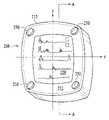
- FIG. 1is a front isometric view of an ambiguous electronic device that can be configured for multiple orientations, under an embodiment of the invention.
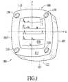
- FIG. 2Ais a front isometric view of an ambiguous electronic device that can be configured for multiple orientations, under another embodiment of the invention.
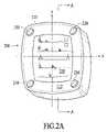
- FIG. 2Bis a cross-sectional view cut along lines A-A of FIG. 2A .
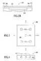
- FIG. 3is a back view of an electronic device including a sensor system for determining orientation information for the electronic device, under another embodiment of the invention.
- FIG. 4is a side view of an electronic device including a sensor system for determining orientation information for an electronic device, under an embodiment of the invention.
- FIG. 5is a method for configuring an electronic device based on orientation information detected from a sensor system, under an embodiment of the invention.
- FIG. 6is a method for configuring an electronic device based on orientation information detected from user-input, under an embodiment of the invention.
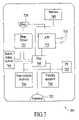
- FIG. 7is a block diagram for an electronic device configured for using orientation information, under an embodiment of the invention.
- Embodiments of the inventiondescribe an ambiguous electronic device having automatic orientation-based user interface features.
- numerous specific detailsare set forth in order to provide a thorough understanding of the present invention. It will be apparent, however, that the present invention may be practiced without these specific details. In other instances, well-known structures and devices are shown in block diagram form in order to avoid unnecessarily obscuring the present invention.
- Embodiments of the inventioninclude an ambiguous electronic device that can detect orientation information.
- Components of the ambiguous device, including user-interface features,are configurable based on the detected orientation of the device.
- an electronic deviceincludes a user-interface feature, a detection mechanism, and one or more components for configuring the user-interface feature.
- the user-interface featureis disposed symmetrically about one or more axes, and is configurable to have any one of multiple orientations.
- the detection mechanismdetects a user-orientation for using the electronic device.
- the componentsare configured to select the orientation of the user-interface feature based on the detected user-orientation, and to configure the user-interface feature according to the selected orientation.
- a user-interface featureis any feature that provides output to the user, or allows the user to enter input into the electronic device.
- Examples of user-interface featuresinclude a display, an input mechanism appearing on a display, or a set of actuatable surfaces.
- a detection mechanismis any device that can detect orientation information, or be used in a manner that will determine orientation.
- detection mechanismsinclude sensors, actuatable surfaces and other mechanisms, that detect how the user has oriented the electronic device when using it.
- the detection mechanismdetects the orientation of the handheld during or right after the electronic device is in a power-on state.
- the one or more componentsmay refer to a processor or other component instructed to perform certain functions.
- Other examples of components in the electronic deviceinclude drivers, such as display drivers.
- Actuatable surfacesinclude surfaces that act as switches when contacted by the user.
- FIG. 1is an isometric view of a configurable, ambiguous electronic device, under an embodiment of the invention.
- An electronic device 100such as shown by FIG. 1 is symmetrical about at least two axes. This symmetry facilitates the electronic device 100 in being configured based on a detected orientation of the electronic device.
- a set of user-interface features for electronic device 100includes a display 120 and an arrangement of buttons 130 .
- a housing 108encases internal components of electronic device 100 , and provides a front panel 112 for the set of user-interface features.
- the housing 108may be referenced by a first and second pair of sides 105 , 115 .
- electronic device 100Because electronic device 100 is ambiguous, it has no designated orientation for its user-interface features until its orientation is determined.
- the layout of the user-interface featuresis symmetrically disposed about the X and Y center-line axes. For example, the top/bottom and left/right sides of the electronic device are unknown when the device is in an ambiguous state.
- the top/bottom and left/right sides of electronic device 100are not designated, but determined after the device is held or in use.
- the user-interface featuresare configured to function using the determined orientation. For example, content appearing on display 120 will have an orientation that matches the device's use.
- Button actionshave set positions, and the buttons 130 that cause those actions to be performed are determined based on the orientation of the device.
- Conventional electronic deviceshave set orientations before and after when they are in use.
- conventional electronic deviceshave housing structures and visual indices to inform the user of the orientation of the electronic device.
- embodiments of the inventionprovide no indication of the device's orientation prior to its use.
- the electronic device 100 and its user-interface featuresmay be symmetrically disposed about one or more axes.
- the housing 108may be symmetrical. No visual indices may be provided to indicate how, for example, a user should hold the electronic device 100 .
- the orientation of the electronic device 100will not matter until the device is held or in use.
- electronic device 100may be referenced against two center-line axes X and Y.
- the lengths of all sides 105 , 115 of electronic device 100are the same, so that electronic device 100 has a square shape.
- Other shapesmay be contemplated for electronic device 100 , including geometries symmetrical about X and/or Y.
- housing 108is rectangular or circular.
- the display 120 and buttons 130are symmetrically disposed on front panel 112 about X and Y.
- the display 120is centrally positioned relative to axes X and Y.
- the buttons 130are positioned on each corner of the square-shaped electronic device 100 .
- Display 120displays content according to an orientation using one or more reference indications on axes X and Y.
- a reference indicationmay determine a top-down or right-left direction for display 120 .
- the reference indicationwill designate one of the axes X, Y as the vertical axis, the other as the horizontal axis. Furthermore, the reference indication will indicate a top/bottom end about the vertical axis and left/right end about the horizontal axis.
- the reference indicationis determined after orientation information is determined from electronic device 100 .
- the orientation informationmay be derived from detection mechanisms, such as described with FIGS. 3 and 4 .
- the orientation informationenables components of electronic device 100 to set the vertical and horizontal directions for display 120 . In this way, content such as text is displayed relative to a top and bottom, and right to left.
- buttons 130are assigned actions based on the orientation information.
- the actionsmay include any one of a set of predefined functions, operations, or programs, so that actuation of one of the buttons causes a corresponding function, operation or program to be performed.
- the action associated with each button 130may be determined by identifying a reference indication using the orientation information.
- the reference indicationcan be used to designate physical locations for where buttons for specified actions are to be located. For example, the reference indication may designate one of the first pair of sides 105 as a left side for housing 108 , and one of the second pair of sides 115 as a right side for housing 108 .
- the button 130 designated to be in one of the corners, such as the top-left corner,may have a pre-selected action assigned to it.
- electronic device 100is equipped to detect orientation information for the electronic device in use. Detection mechanisms, as described in Section C, may be used to provide the orientation information when the device is gripped, or otherwise used.
- the orientation informationmay indicate, for example, how a user is holding the device, whether the user is holding it with left-handedness or right-handedness, and/or whether the user-interface features are facing up or down.
- This orientation informationmay, in turn, be used to designate left, right, top and/or bottom sides on electronic device 100 . In this way, the orientation information for electronic device 100 will appear in a manner that matches a user's orientation for using the device.
- buttonsmay be assigned to actions by having predetermined locations for where buttons for each action is to be located.
- a button-press in the top, left corner, for example,will always identify a certain action.
- the orientation informationis used to identify the top, left corner.
- the same orientation information that configures display 120can be used to set the orientation of buttons 130 .
- FIG. 2Ais a front isometric view of an ambiguous electronic device that can be configured for multiple orientations, under another embodiment of the invention.
- designated contact surfaces 230may be substituted for buttons on a housing 208 .
- a front panel 212 of housing 208provides the user-interface features, including display assembly 220 .
- the display assembly 220may be a contact-sensitive display, comprising a display screen 235 ( FIG. 2B ) and a digitizer pad 225 .
- the digitizer pad 225extends over and beyond the display screen 235 .
- the digitizer pad 225may be used to provide contact surfaces 240 that can be contacted to enter an input signal.
- the contact-sensitive areas 240appear in regions of front panel 212 where digitizer pad 225 extends beyond display surface 235 .
- one of the contact surfaces 240may be touched by the user to signal an interrupt to a processor. In this way, contact surfaces 240 may function the same as buttons 230 .
- FIG. 2Bis a cross-section of FIG. 2A , cut along lines A-A.
- Digitizer pad 225extends over and beyond display screen 235 .
- the digitizer pad 225is configured to detect and interpret user contact on locations corresponding to either designated surfaces 240 , or display assembly 220 .
- Display surface 235is configured to display images in the form of pixels or other graphic elements.
- digitizer pad 225is formed from a material that is integrated into front panel 212 .
- An example of this type of housing construction for an electronic device such as a handheld computeris provided in U.S. patent application Ser. No. 09/871,322, entitled “Threee-Dimensional Contact-Sensitive Feature for Electronic Devices.” This application is incorporated by reference herein in its entirety.
- orientation informationis used to designate actions for designated contact surfaces 240 .
- each contact surface 240may be one of a set, having a fixed position on front panel 212 .
- the orientation informationmay be used to identify what action is to be assigned to that contact surface 240 .
- the location of the contact surfaces 240are not fixed, but determined by the orientation information.
- the orientation informationmay be used to interpret where contact surfaces are to appear on front panel 212 , or elsewhere on housing 208 .
- a region of digitizer pad 225may be activated to receive input through contact with that region. Therefore, the location of each contact surface 240 is determined by the orientation information.
- orientation informationmay determine that four contact surfaces 240 are needed for electronic device 200 , with one contact surface at each corner.
- another configurationmay be interpreted from other orientation information that dictates five contact surfaces are needed for the same electronic device 200 .
- the five contact surfacesmay appear linearly to one side of display assembly 120 .
- Embodiments of the inventionprovide for detection mechanisms that detect orientation information about an electronic device when the device is in use.
- the orientation informationis shared with components that can configure user-interface features for a particular orientation.
- Specific types of detection mechanisms described in this applicationinclude touch-sensitive sensor systems, and user initiated input mechanisms.
- FIG. 3is a bottom view of electronic device 300 adapted to include an orientation-detection mechanism, under an embodiment of the invention.
- the electronic device 300may be square, or otherwise ambiguous in shape.
- the orientation mechanismis a sensor system that detects an orientation of electronic device 300 based on input that is detected by the sensor system.
- the reference pointmay, for example, be a person, or the direction of gravity.
- Sensor system 310may include a plurality of sensor pads 312 .
- Each sensor pad 312corresponds to a contact-sensitive surface that detects contact from a user of electronic device 300 .
- sensor pads 312appear where a user would grip the electronic device 300 .
- sensor pads 312appear on a back panel 320 of electronic device 300 .
- the sensor pads 312may be distributed on back panel 320 . Individual sensor pads 312 may be actuated by users who contact the sensor pads in the course of gripping or handling electronic device 300 . Enough sensor pads 312 may be provided or otherwise positioned so that actuated sensor pads are a subset of all the sensor pads on the back panel 320 .
- Orientation informationmay be detected by identifying the arrangement of sensor pads 312 that are actuated as a result of the user gripping the electronic device 300 .
- components of electronic device 300may be equipped to identify one arrangement of actuated sensor pads 312 as being left-handedness, and another arrangement of actuated sensor pads 312 as being right-handedness.
- sensor pads 312may be gripped on one side of back panel 312 (i.e. to the left of axis X) if the user is right handed.
- FIG. 4is a side view of electronic device 400 adapted to include an orientation-detection mechanism, under another embodiment.
- a sensor systemis positioned on edges of housing 108 ( FIG. 1 ).
- edge surfaces 422extending from either pair of lateral sides 105 , 115 ( FIGS. 1 and 2 ) are provided with sensor pads 412 that detect touch by the user.
- four edge surfaces 422may be assumed for electronic device 400 .
- the sensor pads 412 on each edge surface 422detect touch by the user.
- finger tipsmay extend over and actuate sensor pads 412 on two or more of the edge surfaces 422 .
- the sensor pads 412 that are actuated by a user's gripmay be used to detect orientation information, such as right/left-handedness, and top/down directions of electronic device 100 .
- orientation informationsuch as right/left-handedness, and top/down directions of electronic device 100 .
- the edge surface 422 with the greatest number of actuated surfacesmay be used to identify the handedness of the user.
- the edge surface with the greatest number of actuated surfacesmay indicate the left-right orientation of the device in use.
- orientation informationexamples include left/right-handedness, top/bottom directions, and upward/downward facing. Other types of orientation information may be provided by other embodiments.
- Sensor systemssuch as described with FIGS. 2 and 4 may be implemented through various mechanisms.
- Contact-sensitive electromechanical materialsthat change resistance, inductance, or other electrical properties, may form sensor pads 312 ( FIG. 3 ), 412 ( FIG. 4 ).
- the housing of the electronic devicemay be formed from contact-sensitive material.
- the contact-sensitive materialmay be a unitary or integrated feature of the housing, at least in places where the sensor systems are in place. Electrical connections may be extended to a processor of the electronic device to designated housing locations from where the material is to provide contact-sensitive information.
- the housingmay incorporate the sensor material with no designated housing location for detecting contact. Rather, sufficient portions of the housing are contact-sensitive to enable contact to be located continuously over one or more of the housing's panels or surfaces. This contact may be used to determine orientation information.
- housing panel 320may have an exterior layer formed from material that inherently detects user-contact. This user-contact detected from this type of material may be used to indicate the manner in which the user is holding electronic device 300 . For example, the user's grip on electronic device 300 may detect whether the use is left-handed or right-handed, the left and right sides, the top and bottom sides, and/or an upward direction.
- Electronic muscleis a dielectric elastomer material that can be stretched and allowed to contract. The elastic stresses created from stretching and contracting the electronic muscle work against the electric field of the material and create electrical energy.
- Electronic musclemay be used on some or all of the electronic device's housing.
- the electronic musclemay be made available in areas where users naturally grip the electronic device.
- the electronic musclemay be positioned in places such where the sensor systems are located, such as shown in FIGS. 3 and 4 .
- the electronic energy created from the contact to the electronic muscleis the input corresponding to the orientation information.
- the devicemay be configured based on this orientation information.
- ELEKTEXAnother type of material that can be used as sensor materials is known under the trade name ELEKTEX, manufactured by ELEKSEN LIMITED. This type of material detects contact through a change in electrical resistance.
- An analog-digital converter(see FIG. 7 ) may be used with the sensor materials to detect and interpret contact with the sensor materials.
- the analog-digital converterchanges electrical signals created through changes in the electrical properties of the materials.
- the analog-digital convertermay also detect the position for where contact is occurring on the housing of the electronic device.
- an electronic devicesuch as shown in FIG. 1 may be configured to enable users to enter input that corresponds to orientation information.
- orientation informationis detected through a user-interface feature that is manually operated by the user to inform the electronic device of how it is being held.
- FIG. 6illustrates a method for operating the electronic device using orientation information manually entered by the user.
- the userpresses the button 130 ( FIG. 1 ) that is in a predetermined location on the electronic device 100 when he is holding the device.
- the button 130 in the top left cornercan be pressed by the user to set the orientation of the electronic device 100 .
- the electronic device 100configures the user-interface features based on which button 130 was pressed.
- environmental sensorsmay be used to detect orientation information used to configure the user-interface features of the electronic device.
- environmental sensorsinclude accelerometers or similar devices that can be used to measure gravity.
- FIGS. 5-6illustrate methods for configuring different types of user-interface features based on orientation information detected from a detection mechanism.
- Reference to numerals in other figures of this applicationis for illustrative purposes only.
- the detection mechanismsmay correspond to any combination of sensor systems, user-input mechanisms, sensor materials, or combinations thereof. Examples for detection mechanisms are described with FIGS. 3 and 4 , and elsewhere in Section C.
- FIG. 5illustrates a method for configuring a user-interface feature of an electronic device based to a detected orientation.
- the electronic deviceis ambiguous when not in use, so that the orientation of its user-interface features is unknown.
- the orientation of the electronic deviceis detectable when the electronic device in held or in use. This orientation may be used to configure the user-interface features of electronic device.
- orientation informationis detected.
- the orientation informationmay be detected from any number of sensor systems described above.
- sensor systems described with FIGS. 3 and 4may be used to gain the orientation information.
- sensor materials incorporated into the housing of the materialdetect the orientation of the electronic device.
- step 520an orientation is selected for user-interface features on the electronic device.
- the orientationis selected based on the detected orientation information.
- Step 530provides that the user-interface features are configured according to the selected orientation.
- the user-interface features of electronic device 100include buttons 130 and display 120 .
- the actions assigned to each button 130is unknown when electronic device 100 is ambiguous. Furthermore, the direction content is to appear on display 120 is unknown.
- orientation informationis detected and used to assign actions assigned to specific buttons 130 .
- Each of the buttons 130may be assigned an action based on a relative position of that button to a reference point or designation.
- orientation information about a reference point or designationdetermines the top-down and left-right direction on display 120 .
- the reference point of electronic device 100may coincide with a user's palm and/or fingers in gripping electronic device 100 .
- the detection mechanismmay determine the left and top side of electronic device 100 relative to the user's grip.
- Each of the buttons 130may be assigned an action based on that button's position relative to the user's hand. For example, any button assigned the top left corner position when electronic device 100 is held by the user is assigned a function for that position.
- display 120displays content, receives input, and orients itself based on the detected left-right and top-down reference designations.
- FIG. 6illustrates a method for detecting orientation information through user-input.
- the user-inputmay substitute for sensors and other mechanisms that detect orientation information about the electronic device.
- step 610input is detected that corresponds to orientation information.
- the inputmay correspond to a button press to one of the buttons 130 ( FIG. 1 ).
- the inputmay correspond to actuation of one of the contact surfaces 240 ( FIG. 2 ).
- the inputincludes an attribute or characteristic that serves as a reference designation for electronic device 100 .
- electronic device 100FIG. 1
- Step 620provides that the user-input is translated into orientation information.
- electronic device 100makes a reference designation based on which button 130 is pressed to wake the electronic device 100 from the ambiguous state.
- the top, left corner button pressdesignates the top, bottom, left, and right sides of electronic device 100 .
- Step 630provides that electronic device 100 is configured using the detected orientation information.
- each buttonmay be assigned an action based on its position relative to the top-left corner.
- the displaymay be oriented top-down and left-right based on the proximity of each corner of the display to the button 130 designated as being the top-left corner.
- FIG. 7is a block diagram illustrating a hardware implementation for use with an embodiment where an electronic device is a handheld computer.
- Handheld computerssometimes referred to as PDAs, operate Personal Information Management software. Examples of software that can be operated by a handheld computer includes PALM OS, manufactured by PALM INC., or POCKET PC, manufactured by MICROSOFT.
- a handheld computer 700includes a processor 740 coupled to a first memory 744 (non-volatile) and a second memory 746 (volatile).
- the processor 740is coupled to a display driver 722 .
- the processor 740combines with display driver 722 to process and signal data for presentation on a display assembly 720 .
- the display assembly 720may include screen and digitizer components, as described in FIG. 2B .
- a sensor system 764may be provided to detect orientation information.
- the sensor system 764may comprise information compiled from a plurality of actuated sensor pads, such as shown in FIGS. 3 and 4 .
- the orientation informationmay be detected as an analog value.
- An analog-digital (AD) converter 732is coupled to processor 740 .
- the sensor system 764signals orientation information to processor 740 via A/D converter 732 .
- one or more channels 736 from A/D converter 732maybe used to convert analog input provided by the digitizer, or by another analog input mechanism.
- the handheld computer 700may include one or more expansion ports for coupling to accessory devices, such as cradles, modems, memory units, re-chargers and other devices.
- expansion portsinclude serial ports, Universal Serial Bus (USB) ports, CompactFlash slots and infra-red ports.
- USBUniversal Serial Bus
- an expansion port 702enables one or more types of expansion modules to be connected to processor 740 .
- a power supply 755may provide power to one or more internal components of the handheld computer 700 .
- the power supplymay correspond to a rechargeable or disposable battery set.
- embodiments described hereinprovide for symmetrical electronic devices that are square in shape, other embodiments may use other symmetrical shapes.
- the electronic devicemay be circular in shape.
- While user-interface features described hereinhave focused on display and buttons, other embodiments may provide for other types features that can be oriented with orientation information.
- connector ports, housing features and other componentsare configurable with orientation information.
Landscapes
- Engineering & Computer Science (AREA)
- Computer Hardware Design (AREA)
- Theoretical Computer Science (AREA)
- Human Computer Interaction (AREA)
- Physics & Mathematics (AREA)
- General Engineering & Computer Science (AREA)
- General Physics & Mathematics (AREA)
- User Interface Of Digital Computer (AREA)
Abstract
Description
Claims (26)
Priority Applications (3)
| Application Number | Priority Date | Filing Date | Title |
|---|---|---|---|
| US11/112,173US7256767B2 (en) | 2001-11-30 | 2005-04-22 | Automatic orientation-based user interface for an ambiguous handheld device |
| US11/773,270US7701442B2 (en) | 2001-11-30 | 2007-07-03 | Automatic orientation-based user interface for an ambiguous handheld device |
| US12/730,427US8717293B2 (en) | 2001-11-30 | 2010-03-24 | Automatic orientation-based user interface for an ambiguous handheld device |
Applications Claiming Priority (2)
| Application Number | Priority Date | Filing Date | Title |
|---|---|---|---|
| US10/006,544US6888532B2 (en) | 2001-11-30 | 2001-11-30 | Automatic orientation-based user interface for an ambiguous handheld device |
| US11/112,173US7256767B2 (en) | 2001-11-30 | 2005-04-22 | Automatic orientation-based user interface for an ambiguous handheld device |
Related Parent Applications (1)
| Application Number | Title | Priority Date | Filing Date |
|---|---|---|---|
| US10/006,544ContinuationUS6888532B2 (en) | 2001-11-30 | 2001-11-30 | Automatic orientation-based user interface for an ambiguous handheld device |
Related Child Applications (1)
| Application Number | Title | Priority Date | Filing Date |
|---|---|---|---|
| US11/773,270ContinuationUS7701442B2 (en) | 2001-11-30 | 2007-07-03 | Automatic orientation-based user interface for an ambiguous handheld device |
Publications (2)
| Publication Number | Publication Date |
|---|---|
| US20050184955A1 US20050184955A1 (en) | 2005-08-25 |
| US7256767B2true US7256767B2 (en) | 2007-08-14 |
Family
ID=21721390
Family Applications (4)
| Application Number | Title | Priority Date | Filing Date |
|---|---|---|---|
| US10/006,544Expired - LifetimeUS6888532B2 (en) | 2001-11-30 | 2001-11-30 | Automatic orientation-based user interface for an ambiguous handheld device |
| US11/112,173Expired - LifetimeUS7256767B2 (en) | 2001-11-30 | 2005-04-22 | Automatic orientation-based user interface for an ambiguous handheld device |
| US11/773,270Expired - LifetimeUS7701442B2 (en) | 2001-11-30 | 2007-07-03 | Automatic orientation-based user interface for an ambiguous handheld device |
| US12/730,427Expired - LifetimeUS8717293B2 (en) | 2001-11-30 | 2010-03-24 | Automatic orientation-based user interface for an ambiguous handheld device |
Family Applications Before (1)
| Application Number | Title | Priority Date | Filing Date |
|---|---|---|---|
| US10/006,544Expired - LifetimeUS6888532B2 (en) | 2001-11-30 | 2001-11-30 | Automatic orientation-based user interface for an ambiguous handheld device |
Family Applications After (2)
| Application Number | Title | Priority Date | Filing Date |
|---|---|---|---|
| US11/773,270Expired - LifetimeUS7701442B2 (en) | 2001-11-30 | 2007-07-03 | Automatic orientation-based user interface for an ambiguous handheld device |
| US12/730,427Expired - LifetimeUS8717293B2 (en) | 2001-11-30 | 2010-03-24 | Automatic orientation-based user interface for an ambiguous handheld device |
Country Status (1)
| Country | Link |
|---|---|
| US (4) | US6888532B2 (en) |
Cited By (41)
| Publication number | Priority date | Publication date | Assignee | Title |
|---|---|---|---|---|
| US20050200620A1 (en)* | 2004-03-15 | 2005-09-15 | Benq Corporation | Method for controlling a control of a display |
| US20060012564A1 (en)* | 2004-07-13 | 2006-01-19 | Sony Corporation | Hard disk multimedia player and method |
| US20070152963A1 (en)* | 2001-11-30 | 2007-07-05 | Wong Yoon K | Orientation dependent functionality of an electronic device |
| US20070174782A1 (en)* | 2006-01-25 | 2007-07-26 | Microsoft Corporation | Smart icon placement across desktop size changes |
| US20070296693A1 (en)* | 2001-11-30 | 2007-12-27 | Wong Yoon K | Automatic orientation-based user interface for an ambiguous handheld device |
| US20090117951A1 (en)* | 2007-11-07 | 2009-05-07 | Motorola Inc | Methods and apparatus for user-selectable programmable housing skin sensors for user mode optimization and control |
| US20090225040A1 (en)* | 2008-03-04 | 2009-09-10 | Microsoft Corporation | Central resource for variable orientation user interface |
| US20090300537A1 (en)* | 2008-05-27 | 2009-12-03 | Park Kenneth J | Method and system for changing format for displaying information on handheld device |
| US20100013780A1 (en)* | 2008-07-17 | 2010-01-21 | Sony Corporation | Information processing device, information processing method, and information processing program |
| US20100053089A1 (en)* | 2008-08-27 | 2010-03-04 | Research In Motion Limited | Portable electronic device including touchscreen and method of controlling the portable electronic device |
| US7733637B1 (en) | 2001-04-27 | 2010-06-08 | Palm, Inc. | Keyboard sled with rotating screen |
| US20100207858A1 (en)* | 2009-02-13 | 2010-08-19 | Apple Inc. | LCD Pixel Design Varying by Color |
| US20100208179A1 (en)* | 2009-02-13 | 2010-08-19 | Apple Inc. | Pixel Black Mask Design and Formation Technique |
| US20100207853A1 (en)* | 2009-02-13 | 2010-08-19 | Apple Inc. | Electrodes for use in displays |
| US20100207861A1 (en)* | 2009-02-13 | 2010-08-19 | Apple Inc. | Advanced Pixel Design for Optimized Driving |
| US20100207860A1 (en)* | 2009-02-13 | 2010-08-19 | Apple Inc. | Via design for use in displays |
| US20100207854A1 (en)* | 2009-02-13 | 2010-08-19 | Apple Inc. | Placement and shape of electrodes for use in displays |
| US20100208158A1 (en)* | 2009-02-13 | 2010-08-19 | Apple Inc. | LCD Panel with Index-Matching Passivation Layers |
| US20100207862A1 (en)* | 2009-02-13 | 2010-08-19 | Apple Inc. | Pseudo Multi-Domain Design for Improved Viewing Angle and Color Shift |
| US20100245723A1 (en)* | 2009-03-31 | 2010-09-30 | Apple Inc. | Lcd panel having improved response |
| US20100245224A1 (en)* | 2009-03-27 | 2010-09-30 | Apple Inc. | Lcd electrode arrangement |
| US7859518B1 (en) | 2001-06-04 | 2010-12-28 | Palm, Inc. | Interface for interaction with display visible from both sides |
| US20110084913A1 (en)* | 2009-10-14 | 2011-04-14 | Research In Motion Limited | Touch-sensitive display and method of controlling same |
| US20110160884A1 (en)* | 2009-12-24 | 2011-06-30 | Samsung Electronics Co. Ltd. | Multimedia device and method for controlling operation thereof |
| US8031212B2 (en) | 2000-05-18 | 2011-10-04 | Hewlett-Packard Development Company, L.P. | Reorienting display on portable computing device |
| US20120081845A1 (en)* | 2010-09-30 | 2012-04-05 | Kabushiki Kaisha Toshiba | Information processing apparatus |
| US20120206332A1 (en)* | 2011-02-16 | 2012-08-16 | Sony Corporation | Method and apparatus for orientation sensitive button assignment |
| US8317615B2 (en) | 2010-02-03 | 2012-11-27 | Nintendo Co., Ltd. | Display device, game system, and game method |
| US8339364B2 (en) | 2010-02-03 | 2012-12-25 | Nintendo Co., Ltd. | Spatially-correlated multi-display human-machine interface |
| US8633879B2 (en) | 2009-02-13 | 2014-01-21 | Apple Inc. | Undulating electrodes for improved viewing angle and color shift |
| US8702514B2 (en) | 2010-11-01 | 2014-04-22 | Nintendo Co., Ltd. | Controller device and controller system |
| US8814686B2 (en) | 2010-02-03 | 2014-08-26 | Nintendo Co., Ltd. | Display device, game system, and game method |
| US8845426B2 (en) | 2011-04-07 | 2014-09-30 | Nintendo Co., Ltd. | Input system, information processing device, storage medium storing information processing program, and three-dimensional position calculation method |
| US8913009B2 (en) | 2010-02-03 | 2014-12-16 | Nintendo Co., Ltd. | Spatially-correlated multi-display human-machine interface |
| US8956209B2 (en) | 2010-08-30 | 2015-02-17 | Nintendo Co., Ltd. | Game system, game apparatus, storage medium having game program stored therein, and game process method |
| US8982056B2 (en) | 2011-03-15 | 2015-03-17 | Rosemount Inc. | Software rotatable display |
| USRE45559E1 (en) | 1997-10-28 | 2015-06-09 | Apple Inc. | Portable computers |
| US9132347B2 (en) | 2010-08-30 | 2015-09-15 | Nintendo Co., Ltd. | Game system, game apparatus, storage medium having game program stored therein, and game process method |
| US9199168B2 (en) | 2010-08-06 | 2015-12-01 | Nintendo Co., Ltd. | Game system, game apparatus, storage medium having game program stored therein, and game process method |
| US9448712B2 (en) | 2007-01-07 | 2016-09-20 | Apple Inc. | Application programming interfaces for scrolling operations |
| US10150033B2 (en) | 2010-08-20 | 2018-12-11 | Nintendo Co., Ltd. | Position calculation system, position calculation device, storage medium storing position calculation program, and position calculation method |
Families Citing this family (63)
| Publication number | Priority date | Publication date | Assignee | Title |
|---|---|---|---|---|
| US5978379A (en) | 1997-01-23 | 1999-11-02 | Gadzoox Networks, Inc. | Fiber channel learning bridge, learning half bridge, and protocol |
| US7808479B1 (en) | 2003-09-02 | 2010-10-05 | Apple Inc. | Ambidextrous mouse |
| US7430171B2 (en) | 1998-11-19 | 2008-09-30 | Broadcom Corporation | Fibre channel arbitrated loop bufferless switch circuitry to increase bandwidth without significant increase in cost |
| CN1720578A (en)* | 2000-12-07 | 2006-01-11 | 三因迪斯克公司 | System, method and apparatus for playback of recorded audio, video or other content from non-volatile memory card, compact disk or other media |
| US7542052B2 (en) | 2002-05-31 | 2009-06-02 | Hewlett-Packard Development Company, L.P. | System and method of switching viewing orientations of a display |
| US11275405B2 (en) | 2005-03-04 | 2022-03-15 | Apple Inc. | Multi-functional hand-held device |
| US7656393B2 (en) | 2005-03-04 | 2010-02-02 | Apple Inc. | Electronic device having display and surrounding touch sensitive bezel for user interface and control |
| US7952569B2 (en)* | 2002-08-08 | 2011-05-31 | Hewlett-Packard Development Company, L.P. | System and method of switching between multiple viewing modes in a multi-head computer system |
| US7209124B2 (en) | 2002-08-08 | 2007-04-24 | Hewlett-Packard Development Company, L.P. | Multiple-position docking station for a tablet personal computer |
| US7882162B2 (en)* | 2002-08-08 | 2011-02-01 | Hewlett-Packard Development Company, L.P. | Rapid access to data on a powered down personal computer |
| KR100663478B1 (en)* | 2003-01-30 | 2007-01-02 | 삼성전자주식회사 | Display device and method of mobile terminal |
| US7426329B2 (en) | 2003-03-06 | 2008-09-16 | Microsoft Corporation | Systems and methods for receiving, storing, and rendering digital video, music, and pictures on a personal media player |
| US20040201595A1 (en)* | 2003-04-11 | 2004-10-14 | Microsoft Corporation | Self-orienting display |
| CA2531666A1 (en)* | 2003-07-09 | 2005-01-27 | Wildseed Ltd. | Shared input key method and apparatus |
| JP2005100084A (en)* | 2003-09-25 | 2005-04-14 | Toshiba Corp | Image processing apparatus and method |
| US20050078086A1 (en)* | 2003-10-09 | 2005-04-14 | Grams Richard E. | Method and apparatus for controlled display |
| JP4288134B2 (en)* | 2003-10-16 | 2009-07-01 | 京セラ株式会社 | Imaging device |
| EP2639723A1 (en)* | 2003-10-20 | 2013-09-18 | Zoll Medical Corporation | Portable medical information device with dynamically configurable user interface |
| US7207885B2 (en)* | 2004-01-15 | 2007-04-24 | Espeed, Inc. | System and method for using a game controller device for electronic trading |
| US8170945B2 (en) | 2004-01-15 | 2012-05-01 | Bgc Partners, Inc. | System and method for providing security to a game controller device for electronic trading |
| US8469808B2 (en)* | 2004-01-15 | 2013-06-25 | Bgc Partners, Inc. | System and method for managing a game controller device for electronic trading |
| US8281241B2 (en) | 2004-06-28 | 2012-10-02 | Nokia Corporation | Electronic device and method for providing extended user interface |
| KR101183115B1 (en)* | 2005-07-18 | 2012-09-20 | 삼성전자주식회사 | Method and apparatus for providing touch screen based user interface,and electronic devices including the same |
| US7574715B2 (en)* | 2005-07-20 | 2009-08-11 | Apple Inc. | Disk drive media access system |
| US7532464B2 (en)* | 2005-07-20 | 2009-05-12 | Apple Inc. | Access system for a portable device |
| GB2445505A (en)* | 2005-09-30 | 2008-07-09 | Peratech Ltd | Fabric bag including control device |
| WO2007069116A2 (en)* | 2005-12-12 | 2007-06-21 | Koninklijke Philips Electronics N.V. | A device incorporating a display |
| WO2007096688A1 (en)* | 2006-02-23 | 2007-08-30 | Alon Lotan | A display and actuator device |
| EP1971116B1 (en)* | 2006-03-31 | 2017-09-13 | Drnc Holdings, Inc. | Mobile phone with sensor for detection of user's handling |
| US20080228618A1 (en) | 2007-03-15 | 2008-09-18 | Noviello Joseph C | System And Method For Providing An Operator Interface For Displaying Market Data, Trader Options, And Trader Input |
| US12245028B1 (en)* | 2007-06-27 | 2025-03-04 | ENORCOM Corporation | Intelligent interface mechanism for an electronic system |
| US8068121B2 (en)* | 2007-06-29 | 2011-11-29 | Microsoft Corporation | Manipulation of graphical objects on a display or a proxy device |
| JP5071159B2 (en)* | 2008-02-29 | 2012-11-14 | 富士通株式会社 | Information equipment |
| JP5045559B2 (en)* | 2008-06-02 | 2012-10-10 | 富士通モバイルコミュニケーションズ株式会社 | Mobile device |
| CN101685355B (en)* | 2008-09-28 | 2012-05-02 | 汉王科技股份有限公司 | Multi-directional handwriting track input device and system |
| US20100153313A1 (en)* | 2008-12-15 | 2010-06-17 | Symbol Technologies, Inc. | Interface adaptation system |
| CN101847074A (en)* | 2009-03-26 | 2010-09-29 | 深圳富泰宏精密工业有限公司 | Array functional arrangements, application system and method |
| US8654524B2 (en) | 2009-08-17 | 2014-02-18 | Apple Inc. | Housing as an I/O device |
| CN102770904B (en)* | 2010-02-25 | 2015-04-08 | 富士通株式会社 | Mobile terminal and its operation interval setting method |
| DE102010029565A1 (en)* | 2010-06-01 | 2011-12-01 | Robert Bosch Gmbh | Method for operating a sensor arrangement and sensor arrangement |
| EP2450775A1 (en)* | 2010-10-20 | 2012-05-09 | Sony Ericsson Mobile Communications AB | Image orientation control in a handheld device |
| US9298334B1 (en)* | 2011-02-18 | 2016-03-29 | Marvell International Ltd. | Method and apparatus for providing a user interface having a guided task flow among a plurality of devices |
| US20120220221A1 (en)* | 2011-02-24 | 2012-08-30 | Ontario, Canada) | Communication system providing data transfer direction determination based upon orientation and related methods |
| US8644884B2 (en) | 2011-08-04 | 2014-02-04 | Qualcomm Incorporated | Sensor-based user interface control |
| JP2013065085A (en)* | 2011-09-15 | 2013-04-11 | Nec Saitama Ltd | Portable terminal device and display method therefor |
| USD677589S1 (en)* | 2012-06-01 | 2013-03-12 | Deca International Corp. | Golf GPS device |
| CN103543842B (en)* | 2012-07-16 | 2017-05-24 | 联想(北京)有限公司 | Terminal device |
| US8665238B1 (en) | 2012-09-21 | 2014-03-04 | Google Inc. | Determining a dominant hand of a user of a computing device |
| MX2015007281A (en)* | 2012-12-12 | 2015-08-12 | Koninkl Philips Nv | An automated cardiopulmonary resuscitation device with a display. |
| US10025494B2 (en)* | 2013-01-16 | 2018-07-17 | Samsung Electronics Co., Ltd. | Apparatus and method for an adaptive edge-to-edge display system for multi-touch devices |
| US9741150B2 (en) | 2013-07-25 | 2017-08-22 | Duelight Llc | Systems and methods for displaying representative images |
| US9483087B2 (en) | 2013-11-29 | 2016-11-01 | At&T Intellectual Property I, L.P. | Multi-orientation mobile device, computer-readable storage unit therefor, and methods for using the same |
| WO2015096020A1 (en)* | 2013-12-24 | 2015-07-02 | Intel Corporation | Adaptive enclosure for a mobile computing device |
| USD748504S1 (en)* | 2014-02-28 | 2016-02-02 | Oventrop Gmbh & Co. Kg | Controller face panel |
| US12401911B2 (en) | 2014-11-07 | 2025-08-26 | Duelight Llc | Systems and methods for generating a high-dynamic range (HDR) pixel stream |
| US12401912B2 (en) | 2014-11-17 | 2025-08-26 | Duelight Llc | System and method for generating a digital image |
| JP6020545B2 (en)* | 2014-12-24 | 2016-11-02 | カシオ計算機株式会社 | Imaging apparatus, imaging condition setting method, and imaging condition setting program |
| US20160239138A1 (en)* | 2015-02-17 | 2016-08-18 | Htc Corporation | Mobile device, press detection method and computer-readable recording medium |
| CN107230187B (en) | 2016-03-25 | 2022-05-24 | 北京三星通信技术研究有限公司 | Method and device for processing multimedia information |
| US10477344B1 (en) | 2016-05-17 | 2019-11-12 | CSC Holdings, LLC | Relative device localization |
| US10324620B2 (en) | 2016-09-06 | 2019-06-18 | Apple Inc. | Processing capacitive touch gestures implemented on an electronic device |
| CN112445139A (en)* | 2019-08-30 | 2021-03-05 | 珠海格力电器股份有限公司 | Intelligent magic cube controller |
| US11537239B1 (en) | 2022-01-14 | 2022-12-27 | Microsoft Technology Licensing, Llc | Diffusion-based handedness classification for touch-based input |
Citations (5)
| Publication number | Priority date | Publication date | Assignee | Title |
|---|---|---|---|---|
| US5825675A (en)* | 1993-07-29 | 1998-10-20 | Xerox Corporation | Apparatus and configuration method for a small, hand-held computing device |
| US5936619A (en)* | 1992-09-11 | 1999-08-10 | Canon Kabushiki Kaisha | Information processor |
| US5949408A (en)* | 1995-09-28 | 1999-09-07 | Hewlett-Packard Company | Dual orientation display handheld computer devices |
| US6115025A (en)* | 1997-09-30 | 2000-09-05 | Silicon Graphics, Inc. | System for maintaining orientation of a user interface as a display changes orientation |
| US6888532B2 (en)* | 2001-11-30 | 2005-05-03 | Palmone, Inc. | Automatic orientation-based user interface for an ambiguous handheld device |
Family Cites Families (54)
| Publication number | Priority date | Publication date | Assignee | Title |
|---|---|---|---|---|
| JPS61216417A (en)* | 1985-03-22 | 1986-09-26 | 利昌工業株式会社 | High voltage capacitor |
| US4564751A (en) | 1985-03-26 | 1986-01-14 | The Legacy Group Research And Development Limited Partnership | Wrap-around auxiliary keyboard |
| JPS63306054A (en)* | 1987-06-08 | 1988-12-14 | Sharp Corp | Printing method |
| US4969647A (en)* | 1989-06-02 | 1990-11-13 | Atari Corporation | Invertible hand-held electronic game apparatus |
| US4969830A (en)* | 1989-06-12 | 1990-11-13 | Grid Systems Corporation | Connection between portable computer components |
| US5227953A (en)* | 1991-10-18 | 1993-07-13 | Hewlett-Packard Company | Apparatus for retaining and electrically interconnecting multiple devices |
| DE69331535T2 (en)* | 1992-09-11 | 2002-08-22 | Canon K.K., Tokio/Tokyo | Computing device |
| US5432720A (en)* | 1992-11-13 | 1995-07-11 | International Business Machines Corporation | Rotatable pen-based computer |
| US5675524A (en)* | 1993-11-15 | 1997-10-07 | Ete Inc. | Portable apparatus for providing multiple integrated communication media |
| US5661632A (en)* | 1994-01-04 | 1997-08-26 | Dell Usa, L.P. | Hand held computer with dual display screen orientation capability controlled by toggle switches having first and second non-momentary positions |
| WO1995019030A1 (en)* | 1994-01-05 | 1995-07-13 | Pois, Inc. | Apparatus and method for a personal onboard information system |
| JPH0962419A (en)* | 1995-08-25 | 1997-03-07 | Mitsumi Electric Co Ltd | Wireless data input device |
| US5734875A (en)* | 1996-02-05 | 1998-03-31 | Seiko Epson Corporation | Hardware that rotates an image for portrait-oriented display |
| US6396483B1 (en)* | 1996-06-28 | 2002-05-28 | Jeffrey H. Hiller | Keyboard incorporating multi-function flat-panel input device and/or display |
| US6137468A (en)* | 1996-10-15 | 2000-10-24 | International Business Machines Corporation | Method and apparatus for altering a display in response to changes in attitude relative to a plane |
| US5949643A (en)* | 1996-11-18 | 1999-09-07 | Batio; Jeffry | Portable computer having split keyboard and pivotal display screen halves |
| IES960815A2 (en)* | 1996-11-18 | 1997-11-19 | Alps Electric Ireland Ltd | Computer keyboard with integral encoded device reader |
| US5986634A (en)* | 1996-12-11 | 1999-11-16 | Silicon Light Machines | Display/monitor with orientation dependent rotatable image |
| JP2957507B2 (en)* | 1997-02-24 | 1999-10-04 | インターナショナル・ビジネス・マシーンズ・コーポレイション | Small information processing equipment |
| US5841424A (en)* | 1997-03-03 | 1998-11-24 | Lextron Systems, Inc. | USB to multiple connect and support bays for peripheral devices |
| US6972945B1 (en)* | 1997-10-17 | 2005-12-06 | Gateway Inc. | Modular computer device and computer keyboard for modular device |
| GB9722766D0 (en)* | 1997-10-28 | 1997-12-24 | British Telecomm | Portable computers |
| US6104604A (en)* | 1998-01-06 | 2000-08-15 | Gateway 2000, Inc. | Modular keyboard |
| US5973664A (en)* | 1998-03-19 | 1999-10-26 | Portrait Displays, Inc. | Parameterized image orientation for computer displays |
| DE19824100A1 (en)* | 1998-05-29 | 1999-12-23 | Mannesmann Vdo Ag | Electronic device with a rotary switch and a display screen |
| US6088021A (en)* | 1998-06-03 | 2000-07-11 | Gateway, Inc. | Peripheral input device having a retractable cord |
| US6580421B1 (en)* | 1998-06-25 | 2003-06-17 | Micron Technology, Inc. | Ergonomic keyboard |
| US6154759A (en)* | 1998-07-10 | 2000-11-28 | Chou; Cheng-Haw | Visiting card computer system |
| US6512511B2 (en)* | 1998-07-20 | 2003-01-28 | Alphagrip, Inc. | Hand grippable combined keyboard and game controller system |
| US6282082B1 (en)* | 1998-07-31 | 2001-08-28 | Qubit, Llc | Case for a modular tablet computer system |
| US6185095B1 (en)* | 1998-08-28 | 2001-02-06 | Hewlett-Packard Company | Computer docking station with retractable release lever |
| KR100312486B1 (en)* | 1998-11-13 | 2002-02-28 | 구자홍 | Automatic rotating device of video display device and its rotation method |
| US6215420B1 (en)* | 1999-01-06 | 2001-04-10 | Coach Master Int'l Corp. | Keyboard (I) |
| US6259769B1 (en)* | 1999-05-04 | 2001-07-10 | Cubic Corporation | Portable smart card communication device |
| US6181284B1 (en)* | 1999-05-28 | 2001-01-30 | 3 Com Corporation | Antenna for portable computers |
| US6433791B2 (en)* | 1999-08-10 | 2002-08-13 | Smar Research Corporation | Displaceable display arrangement |
| JP4018855B2 (en)* | 1999-11-22 | 2007-12-05 | Necアクセステクニカ株式会社 | Touch panel input coordinate conversion apparatus and touch panel input coordinate conversion method |
| US6597384B1 (en)* | 1999-12-22 | 2003-07-22 | Intel Corporation | Automatic reorienting of screen orientation using touch sensitive system |
| US6454759B2 (en)* | 2000-02-28 | 2002-09-24 | The Regents Of The University Of California | Microfabricated injectable drug delivery system |
| US6580932B1 (en)* | 2000-05-31 | 2003-06-17 | Nokia Mobile Phones Limited | Foldable keyboard for mobile communications device |
| US6801796B2 (en)* | 2000-05-31 | 2004-10-05 | Nokia Mobile Phones Ltd. | Soft keys for a mobile communications device having moveable panels |
| US20020064259A1 (en)* | 2000-11-29 | 2002-05-30 | Wen-Sung Tsai | Portable sub-service station |
| US6504709B2 (en)* | 2000-12-08 | 2003-01-07 | Silitek Corporation Corporation | Input device capable of joining modules |
| US6747635B2 (en)* | 2000-12-16 | 2004-06-08 | Kamran Ossia | Multi-mode handheld computer |
| US6850784B2 (en)* | 2001-01-31 | 2005-02-01 | Microsoft Corporation | Modular two-body design for integration of mobile computing device features with a wireless communication device |
| US7142195B2 (en)* | 2001-06-04 | 2006-11-28 | Palm, Inc. | Interface for interaction with display visible from both sides |
| US20030093298A1 (en)* | 2001-10-12 | 2003-05-15 | Javier Hernandez | System and method for providing secure remote access to patient files by authenticating personnel with biometric data |
| US7159194B2 (en)* | 2001-11-30 | 2007-01-02 | Palm, Inc. | Orientation dependent functionality of an electronic device |
| US6628508B2 (en)* | 2002-02-21 | 2003-09-30 | Mobicom Corporation | Portable terminal with foldable keyboard |
| US6786823B2 (en)* | 2002-12-02 | 2004-09-07 | Chicony Electronics Co., Ltd. | Game keyboard device |
| USD492294S1 (en)* | 2002-12-10 | 2004-06-29 | Young S. Kim | Game controller for mobile telephone |
| JP4177142B2 (en)* | 2003-03-10 | 2008-11-05 | 富士通コンポーネント株式会社 | Coordinate input device and drive device |
| US20040223004A1 (en)* | 2003-05-05 | 2004-11-11 | Lincke Scott D. | System and method for implementing a landscape user experience in a hand-held computing device |
| TWI220234B (en)* | 2003-10-21 | 2004-08-11 | Ind Tech Res Inst | A method to simulate animated images for an object |
- 2001
- 2001-11-30USUS10/006,544patent/US6888532B2/ennot_activeExpired - Lifetime
- 2005
- 2005-04-22USUS11/112,173patent/US7256767B2/ennot_activeExpired - Lifetime
- 2007
- 2007-07-03USUS11/773,270patent/US7701442B2/ennot_activeExpired - Lifetime
- 2010
- 2010-03-24USUS12/730,427patent/US8717293B2/ennot_activeExpired - Lifetime
Patent Citations (5)
| Publication number | Priority date | Publication date | Assignee | Title |
|---|---|---|---|---|
| US5936619A (en)* | 1992-09-11 | 1999-08-10 | Canon Kabushiki Kaisha | Information processor |
| US5825675A (en)* | 1993-07-29 | 1998-10-20 | Xerox Corporation | Apparatus and configuration method for a small, hand-held computing device |
| US5949408A (en)* | 1995-09-28 | 1999-09-07 | Hewlett-Packard Company | Dual orientation display handheld computer devices |
| US6115025A (en)* | 1997-09-30 | 2000-09-05 | Silicon Graphics, Inc. | System for maintaining orientation of a user interface as a display changes orientation |
| US6888532B2 (en)* | 2001-11-30 | 2005-05-03 | Palmone, Inc. | Automatic orientation-based user interface for an ambiguous handheld device |
Cited By (74)
| Publication number | Priority date | Publication date | Assignee | Title |
|---|---|---|---|---|
| USRE45559E1 (en) | 1997-10-28 | 2015-06-09 | Apple Inc. | Portable computers |
| USRE46548E1 (en) | 1997-10-28 | 2017-09-12 | Apple Inc. | Portable computers |
| US8031212B2 (en) | 2000-05-18 | 2011-10-04 | Hewlett-Packard Development Company, L.P. | Reorienting display on portable computing device |
| US9261909B2 (en) | 2001-04-27 | 2016-02-16 | Qualcomm Incorporated | Keyboard sled with rotating screen |
| US20110075339A1 (en)* | 2001-04-27 | 2011-03-31 | Palm, Inc. | Keyboard sled with rotating screen |
| US7733637B1 (en) | 2001-04-27 | 2010-06-08 | Palm, Inc. | Keyboard sled with rotating screen |
| US7859518B1 (en) | 2001-06-04 | 2010-12-28 | Palm, Inc. | Interface for interaction with display visible from both sides |
| US7701442B2 (en)* | 2001-11-30 | 2010-04-20 | Palm, Inc. | Automatic orientation-based user interface for an ambiguous handheld device |
| US20070296693A1 (en)* | 2001-11-30 | 2007-12-27 | Wong Yoon K | Automatic orientation-based user interface for an ambiguous handheld device |
| US20070152963A1 (en)* | 2001-11-30 | 2007-07-05 | Wong Yoon K | Orientation dependent functionality of an electronic device |
| US8717293B2 (en) | 2001-11-30 | 2014-05-06 | Qualcomm Incorporated | Automatic orientation-based user interface for an ambiguous handheld device |
| US7508375B2 (en)* | 2004-03-15 | 2009-03-24 | Qisda Corporation | Method for controlling a control of a display |
| US20050200620A1 (en)* | 2004-03-15 | 2005-09-15 | Benq Corporation | Method for controlling a control of a display |
| US20060012564A1 (en)* | 2004-07-13 | 2006-01-19 | Sony Corporation | Hard disk multimedia player and method |
| US7730422B2 (en)* | 2006-01-25 | 2010-06-01 | Microsoft Corporation | Smart icon placement across desktop size changes |
| US20070174782A1 (en)* | 2006-01-25 | 2007-07-26 | Microsoft Corporation | Smart icon placement across desktop size changes |
| US9448712B2 (en) | 2007-01-07 | 2016-09-20 | Apple Inc. | Application programming interfaces for scrolling operations |
| US9760272B2 (en) | 2007-01-07 | 2017-09-12 | Apple Inc. | Application programming interfaces for scrolling operations |
| US10481785B2 (en) | 2007-01-07 | 2019-11-19 | Apple Inc. | Application programming interfaces for scrolling operations |
| US10817162B2 (en) | 2007-01-07 | 2020-10-27 | Apple Inc. | Application programming interfaces for scrolling operations |
| US20090117951A1 (en)* | 2007-11-07 | 2009-05-07 | Motorola Inc | Methods and apparatus for user-selectable programmable housing skin sensors for user mode optimization and control |
| US8107878B2 (en)* | 2007-11-07 | 2012-01-31 | Motorola Mobility, Inc. | Methods and apparatus for user-selectable programmable housing skin sensors for user mode optimization and control |
| US20090225040A1 (en)* | 2008-03-04 | 2009-09-10 | Microsoft Corporation | Central resource for variable orientation user interface |
| US20090300537A1 (en)* | 2008-05-27 | 2009-12-03 | Park Kenneth J | Method and system for changing format for displaying information on handheld device |
| US9411503B2 (en)* | 2008-07-17 | 2016-08-09 | Sony Corporation | Information processing device, information processing method, and information processing program |
| US20100013780A1 (en)* | 2008-07-17 | 2010-01-21 | Sony Corporation | Information processing device, information processing method, and information processing program |
| US20100053089A1 (en)* | 2008-08-27 | 2010-03-04 | Research In Motion Limited | Portable electronic device including touchscreen and method of controlling the portable electronic device |
| US20100207860A1 (en)* | 2009-02-13 | 2010-08-19 | Apple Inc. | Via design for use in displays |
| US8390553B2 (en) | 2009-02-13 | 2013-03-05 | Apple Inc. | Advanced pixel design for optimized driving |
| US20100207858A1 (en)* | 2009-02-13 | 2010-08-19 | Apple Inc. | LCD Pixel Design Varying by Color |
| US20100208179A1 (en)* | 2009-02-13 | 2010-08-19 | Apple Inc. | Pixel Black Mask Design and Formation Technique |
| US20100207853A1 (en)* | 2009-02-13 | 2010-08-19 | Apple Inc. | Electrodes for use in displays |
| US20100207861A1 (en)* | 2009-02-13 | 2010-08-19 | Apple Inc. | Advanced Pixel Design for Optimized Driving |
| US8294647B2 (en) | 2009-02-13 | 2012-10-23 | Apple Inc. | LCD pixel design varying by color |
| US9612489B2 (en) | 2009-02-13 | 2017-04-04 | Apple Inc. | Placement and shape of electrodes for use in displays |
| US20100207862A1 (en)* | 2009-02-13 | 2010-08-19 | Apple Inc. | Pseudo Multi-Domain Design for Improved Viewing Angle and Color Shift |
| US20100208158A1 (en)* | 2009-02-13 | 2010-08-19 | Apple Inc. | LCD Panel with Index-Matching Passivation Layers |
| US8345177B2 (en) | 2009-02-13 | 2013-01-01 | Shih Chang Chang | Via design for use in displays |
| US20100207854A1 (en)* | 2009-02-13 | 2010-08-19 | Apple Inc. | Placement and shape of electrodes for use in displays |
| US8531408B2 (en) | 2009-02-13 | 2013-09-10 | Apple Inc. | Pseudo multi-domain design for improved viewing angle and color shift |
| US8558978B2 (en) | 2009-02-13 | 2013-10-15 | Apple Inc. | LCD panel with index-matching passivation layers |
| US8587758B2 (en) | 2009-02-13 | 2013-11-19 | Apple Inc. | Electrodes for use in displays |
| US8633879B2 (en) | 2009-02-13 | 2014-01-21 | Apple Inc. | Undulating electrodes for improved viewing angle and color shift |
| US20100245224A1 (en)* | 2009-03-27 | 2010-09-30 | Apple Inc. | Lcd electrode arrangement |
| US8111232B2 (en) | 2009-03-27 | 2012-02-07 | Apple Inc. | LCD electrode arrangement |
| US8294850B2 (en) | 2009-03-31 | 2012-10-23 | Apple Inc. | LCD panel having improved response |
| US20100245723A1 (en)* | 2009-03-31 | 2010-09-30 | Apple Inc. | Lcd panel having improved response |
| US8766926B2 (en) | 2009-10-14 | 2014-07-01 | Blackberry Limited | Touch-sensitive display and method of controlling same |
| US20110084913A1 (en)* | 2009-10-14 | 2011-04-14 | Research In Motion Limited | Touch-sensitive display and method of controlling same |
| US20110160884A1 (en)* | 2009-12-24 | 2011-06-30 | Samsung Electronics Co. Ltd. | Multimedia device and method for controlling operation thereof |
| US9304613B2 (en)* | 2009-12-24 | 2016-04-05 | Samsung Electronics Co., Ltd. | Multimedia device and method for controlling operation thereof |
| US8317615B2 (en) | 2010-02-03 | 2012-11-27 | Nintendo Co., Ltd. | Display device, game system, and game method |
| US8684842B2 (en) | 2010-02-03 | 2014-04-01 | Nintendo Co., Ltd. | Display device, game system, and game process method |
| US8913009B2 (en) | 2010-02-03 | 2014-12-16 | Nintendo Co., Ltd. | Spatially-correlated multi-display human-machine interface |
| US9776083B2 (en) | 2010-02-03 | 2017-10-03 | Nintendo Co., Ltd. | Spatially-correlated multi-display human-machine interface |
| US8961305B2 (en) | 2010-02-03 | 2015-02-24 | Nintendo Co., Ltd. | Game system, controller device and game method |
| US8339364B2 (en) | 2010-02-03 | 2012-12-25 | Nintendo Co., Ltd. | Spatially-correlated multi-display human-machine interface |
| US8896534B2 (en) | 2010-02-03 | 2014-11-25 | Nintendo Co., Ltd. | Spatially-correlated multi-display human-machine interface |
| US9358457B2 (en) | 2010-02-03 | 2016-06-07 | Nintendo Co., Ltd. | Game system, controller device, and game method |
| US8814686B2 (en) | 2010-02-03 | 2014-08-26 | Nintendo Co., Ltd. | Display device, game system, and game method |
| US9199168B2 (en) | 2010-08-06 | 2015-12-01 | Nintendo Co., Ltd. | Game system, game apparatus, storage medium having game program stored therein, and game process method |
| US10150033B2 (en) | 2010-08-20 | 2018-12-11 | Nintendo Co., Ltd. | Position calculation system, position calculation device, storage medium storing position calculation program, and position calculation method |
| US8956209B2 (en) | 2010-08-30 | 2015-02-17 | Nintendo Co., Ltd. | Game system, game apparatus, storage medium having game program stored therein, and game process method |
| US9132347B2 (en) | 2010-08-30 | 2015-09-15 | Nintendo Co., Ltd. | Game system, game apparatus, storage medium having game program stored therein, and game process method |
| US20120081845A1 (en)* | 2010-09-30 | 2012-04-05 | Kabushiki Kaisha Toshiba | Information processing apparatus |
| US8814680B2 (en) | 2010-11-01 | 2014-08-26 | Nintendo Co., Inc. | Controller device and controller system |
| US8804326B2 (en) | 2010-11-01 | 2014-08-12 | Nintendo Co., Ltd. | Device support system and support device |
| US8702514B2 (en) | 2010-11-01 | 2014-04-22 | Nintendo Co., Ltd. | Controller device and controller system |
| US8827818B2 (en) | 2010-11-01 | 2014-09-09 | Nintendo Co., Ltd. | Controller device and information processing device |
| US9889384B2 (en) | 2010-11-01 | 2018-02-13 | Nintendo Co., Ltd. | Controller device and controller system |
| US9272207B2 (en) | 2010-11-01 | 2016-03-01 | Nintendo Co., Ltd. | Controller device and controller system |
| US20120206332A1 (en)* | 2011-02-16 | 2012-08-16 | Sony Corporation | Method and apparatus for orientation sensitive button assignment |
| US8982056B2 (en) | 2011-03-15 | 2015-03-17 | Rosemount Inc. | Software rotatable display |
| US8845426B2 (en) | 2011-04-07 | 2014-09-30 | Nintendo Co., Ltd. | Input system, information processing device, storage medium storing information processing program, and three-dimensional position calculation method |
Also Published As
| Publication number | Publication date |
|---|---|
| US20050184955A1 (en) | 2005-08-25 |
| US6888532B2 (en) | 2005-05-03 |
| US20100171699A1 (en) | 2010-07-08 |
| US20070296693A1 (en) | 2007-12-27 |
| US7701442B2 (en) | 2010-04-20 |
| US8717293B2 (en) | 2014-05-06 |
| US20030103038A1 (en) | 2003-06-05 |
Similar Documents
| Publication | Publication Date | Title |
|---|---|---|
| US7256767B2 (en) | Automatic orientation-based user interface for an ambiguous handheld device | |
| US10671280B2 (en) | User input apparatus, computer connected to user input apparatus, and control method for computer connected to user input apparatus, and storage medium | |
| JP6321113B2 (en) | Handheld electronic device with multi-touch sensing device | |
| US7659885B2 (en) | Method and system for using a keyboard overlay with a touch-sensitive display screen | |
| US6924752B2 (en) | Three-dimensional contact-sensitive feature for electronic devices | |
| JP4787087B2 (en) | Position detection apparatus and information processing apparatus | |
| TW200822682A (en) | Multi-function key with scrolling | |
| JP2010244302A (en) | Input device and input processing method | |
| US20130063385A1 (en) | Portable information terminal and method for controlling same | |
| JP2021033543A (en) | Input device | |
| CN102736783A (en) | Portable terminal apparatus and computer readable medium | |
| JP2023128145A (en) | coordinate input device | |
| US20090091535A1 (en) | Keyboard with touch-sensor space bar | |
| WO2006052175A1 (en) | Terminal design with keyboard arranged on the back or side surface of the terminal | |
| CN217426087U (en) | Input device | |
| JP3289689B2 (en) | Keyboard device | |
| US7782300B2 (en) | Portable computer | |
| JPH0683537A (en) | Touch panel type information processor | |
| CN101124532A (en) | Computer input device | |
| US8581846B2 (en) | Sensing computer mouse having touch-sensitive members disposed on curved bottom surface | |
| CN215298066U (en) | Electronic device | |
| JP6627087B2 (en) | Input device | |
| EP1965292A2 (en) | Mobile communication terminal with 2 dimentional input device | |
| KR20030060355A (en) | Portable computer and controlling method thereof | |
| JPH0575836U (en) | Information processing equipment |
Legal Events
| Date | Code | Title | Description |
|---|---|---|---|
| STCF | Information on status: patent grant | Free format text:PATENTED CASE | |
| FEPP | Fee payment procedure | Free format text:PAYOR NUMBER ASSIGNED (ORIGINAL EVENT CODE: ASPN); ENTITY STATUS OF PATENT OWNER: LARGE ENTITY | |
| AS | Assignment | Owner name:JPMORGAN CHASE BANK, N.A., NEW YORK Free format text:SECURITY AGREEMENT;ASSIGNOR:PALM, INC.;REEL/FRAME:020317/0256 Effective date:20071024 | |
| AS | Assignment | Owner name:PALM, INC., CALIFORNIA Free format text:RELEASE BY SECURED PARTY;ASSIGNOR:JPMORGAN CHASE BANK, N.A., AS ADMINISTRATIVE AGENT;REEL/FRAME:024630/0474 Effective date:20100701 | |
| AS | Assignment | Owner name:HEWLETT-PACKARD DEVELOPMENT COMPANY, L.P., TEXAS Free format text:ASSIGNMENT OF ASSIGNORS INTEREST;ASSIGNOR:PALM, INC.;REEL/FRAME:025204/0809 Effective date:20101027 | |
| FPAY | Fee payment | Year of fee payment:4 | |
| AS | Assignment | Owner name:PALM, INC., CALIFORNIA Free format text:ASSIGNMENT OF ASSIGNORS INTEREST;ASSIGNOR:HEWLETT-PACKARD DEVELOPMENT COMPANY, L.P.;REEL/FRAME:030341/0459 Effective date:20130430 | |
| FEPP | Fee payment procedure | Free format text:PAYER NUMBER DE-ASSIGNED (ORIGINAL EVENT CODE: RMPN); ENTITY STATUS OF PATENT OWNER: LARGE ENTITY Free format text:PAYOR NUMBER ASSIGNED (ORIGINAL EVENT CODE: ASPN); ENTITY STATUS OF PATENT OWNER: LARGE ENTITY | |
| AS | Assignment | Owner name:PALM, INC., CALIFORNIA Free format text:ASSIGNMENT OF ASSIGNORS INTEREST;ASSIGNORS:WONG, YOON KEAN;HANSON, WILLIAM ROBERT;GETTEMY, SHAWN;SIGNING DATES FROM 20011129 TO 20011130;REEL/FRAME:031725/0522 | |
| AS | Assignment | Owner name:HEWLETT-PACKARD DEVELOPMENT COMPANY, L.P., TEXAS Free format text:ASSIGNMENT OF ASSIGNORS INTEREST;ASSIGNOR:PALM, INC.;REEL/FRAME:031837/0659 Effective date:20131218 Owner name:PALM, INC., CALIFORNIA Free format text:ASSIGNMENT OF ASSIGNORS INTEREST;ASSIGNOR:HEWLETT-PACKARD DEVELOPMENT COMPANY, L.P.;REEL/FRAME:031837/0544 Effective date:20131218 Owner name:HEWLETT-PACKARD DEVELOPMENT COMPANY, L.P., TEXAS Free format text:ASSIGNMENT OF ASSIGNORS INTEREST;ASSIGNOR:PALM, INC.;REEL/FRAME:031837/0239 Effective date:20131218 | |
| AS | Assignment | Owner name:QUALCOMM INCORPORATED, CALIFORNIA Free format text:ASSIGNMENT OF ASSIGNORS INTEREST;ASSIGNORS:HEWLETT-PACKARD COMPANY;HEWLETT-PACKARD DEVELOPMENT COMPANY, L.P.;PALM, INC.;REEL/FRAME:032126/0541 Effective date:20140123 | |
| FPAY | Fee payment | Year of fee payment:8 | |
| MAFP | Maintenance fee payment | Free format text:PAYMENT OF MAINTENANCE FEE, 12TH YEAR, LARGE ENTITY (ORIGINAL EVENT CODE: M1553); ENTITY STATUS OF PATENT OWNER: LARGE ENTITY Year of fee payment:12 |